

MARITIME
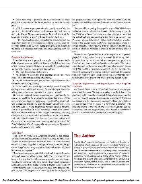
JhJ6306wame
JhJ6306wame

Create successful ePaper yourself
Turn your PDF publications into a flip-book with our unique Google optimized e-Paper software.
• Local pitch map – provides the measured value of local<br />
pitch for a segment of the blade surface at each inspection<br />
point.<br />
• XYZ location map – provides the coordinates of the inspection<br />
points in a Cartesian coordinate system. Each inspection<br />
point has an X value representing the axial height of the<br />
blade at a specified Y and Z ordinate from the shaft axis.<br />
• X-R-Theta location map – provides the coordinates of the<br />
inspection points in a cylindrical coordinate system. Each inspection<br />
point has an X value representing the axial height of<br />
the blade at a specified radius (R) and angle (Theta) from the<br />
shaft axis.<br />
Castings and Patterns<br />
Manufacturing a new propeller or replacement blades typically<br />
requires geometry different from the final design as part<br />
of the foundry process. Building a propeller by sand-casting,<br />
for example, requires three critical geometries:<br />
• The final design shape (of course).<br />
• An expanded geometry that includes additional “mill<br />
stock” thickness for machining or grinding.<br />
• Pattern geometry which will account for deformation and<br />
shape changes during casting.<br />
In other words, the shrinkage and deformation during the<br />
casting plus the additional material for machining or hand-finishing<br />
must be built into a production or patter model.<br />
Generating rational pattern geometry can significantly increase<br />
the workload for a propeller designer, but much of this<br />
process can be effectively automated. PropCad Premium’s Pattern<br />
Corrections tool allows users to directly specify mill stock<br />
and shrinkage to create machining models, casting patterns,<br />
and mold geometries. A major advantage is that these corrections<br />
are applied directly to the design parameters, allowing<br />
calculation and visualization of sections, blade parameters,<br />
and radial distributions. The Pattern Corrections utility will<br />
document these important corrections by storing them with the<br />
PropCad design file. Consequently, adjustments to the pattern<br />
can be made rapidly and easily.<br />
Case Study<br />
The value of PropCad to Argonaut Enterprises for propeller<br />
inspection and documentation was described by Mr. Doerr.<br />
“Since 2012 when we first purchased PropCad, we have found<br />
several customer-supplied drawings to have numerous design<br />
errors. PropCad has truly saved us time and money on these<br />
build-to-print projects.”<br />
“Last year a customer provided a 144 inch four-blade stainless<br />
steel propeller with a broken blade. This customer did not<br />
have a drawing for the 30-year old propeller but was happy<br />
with the performance right up to the day they struck something<br />
and had broken off the blade. As long as there is an ocean floor<br />
or river bottom, there will always be a need for a propeller repair<br />
facility. This project was Classed by ABS so all aspects of<br />
the project required ABS approval; from the initial drawing,<br />
casting and final inspection of the newly manufactured propeller.”<br />
“We started by scanning the propeller with a 3D CMM device<br />
and created a three-dimensional model of the damaged propeller.<br />
PropCad’s Scan Converter was then applied to develop<br />
the cylindrical sections and build the design as scanned into<br />
PropCad. We used the Class Feature within PropCad to determine<br />
if the design meets ABS Class requirements. Once the<br />
design model is completed, we used the Pattern Compensation<br />
utility in PropCad Premium to create a pattern drawing and 3D<br />
data.”<br />
Shown in the figures below is an example of an Argonaut<br />
propeller project where they a) scanned the existing blade,<br />
b) created the geometric model and compensated pattern in<br />
PropCad, and c) cast and machined a replacement. The newly<br />
manufactured replacement propeller was also scanned into a<br />
3D CAD model for inspection and QA. As can be seen, the<br />
finished replacement propeller faithfully matched the original<br />
with very high precision – and does so in a way that that blade<br />
is mathematically smooth and erases existing design errors.<br />
Propeller Replacement and Repair Success with PropCad<br />
Premium<br />
As Darryl Doerr puts it, “PropCad Premium is an integral<br />
part of our business. We began working with the folks at HydroComp<br />
in 2012 and have expanded that relationship over the<br />
years on several naval and commercial projects. HydroComp<br />
has specially tailored numerous upgrades to PropCad to help us<br />
get the desired result we need. It is rare when a company will<br />
take the time to work one-on-one to develop features and enhancements<br />
that did not previously exist. Going the extra mile<br />
is truly a trait instilled in the HydroComp philosophy.”<br />
The Author<br />
Donald MacPherson is co-founder and Technical Director of<br />
HydroComp. Widely regarded as one of the industry’s foremost<br />
experts in parametric performance prediction for marine vehicles,<br />
MacPherson oversees all software product development<br />
and technical consulting services. He is a graduate of the Webb<br />
Institute of Naval Architecture, a Fellow of the Society of Naval<br />
Architects and Marine Engineers, a member of the SNAME H-8<br />
Propulsion Hydrodynamics Panel, and a frequent author and<br />
speaker on ship resistance and propulsion, sea trial and bollard<br />
pull analysis, and propulsor design.<br />
Reprinted with Permission from the November 2016 edition of Maritime Reporter & Engineering News - www.marinelink.com