5-35 Proportional Throttle Valves Series TDL ... - kstci.com.tw
5-35 Proportional Throttle Valves Series TDL ... - kstci.com.tw
5-35 Proportional Throttle Valves Series TDL ... - kstci.com.tw

You also want an ePaper? Increase the reach of your titles
YUMPU automatically turns print PDFs into web optimized ePapers that Google loves.
Catalogue HY11-2500/UK<br />
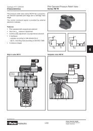
Characteristics<br />
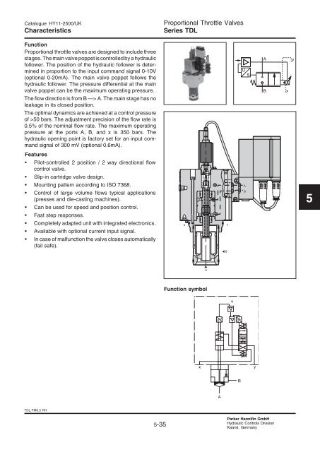
Function<br />
<strong>Proportional</strong> throttle valves are designed to include three<br />
stages. The main valve poppet is controlled by a hydraulic<br />
follower. The position of the hydraulic follower is determined<br />
in proportion to the input <strong>com</strong>mand signal 0-10V<br />
(optional 0-20mA). The main valve poppet follows the<br />
hydraulic follower. The pressure differential at the main<br />
valve poppet can be the maximum operating pressure.<br />
The flow direction is from B —> A. The main stage has no<br />
leakage in its closed position.<br />
The optimal dynamics are achieved at a control pressure<br />
of >50 bars. The adjustment precision of the flow rate is<br />
0.5% of the nominal flow rate. The maximum operating<br />
pressure at the ports A, B, and x is <strong>35</strong>0 bars. The<br />
hydraulic opening point is factory set for an input <strong>com</strong>mand<br />
signal of 300 mV (optional 0.6mA).<br />
Features<br />
• Pilot-controlled 2 position / 2 way directional flow<br />
control valve.<br />
Slip-in cartridge valve design.<br />
Mounting pattern according to ISO 7368.<br />
Control of large volume flows typical applications<br />
(presses and die-casting machines).<br />
Can be used for speed and position control.<br />
Fast step responses.<br />
Completely adapted unit with integrated electronics.<br />
Available with optional current input signal.<br />
In case of malfunction the valve closes automatically<br />
(fail safe).<br />
<strong>TDL</strong>.PM6.5 RH<br />
5-<strong>35</strong><br />
<strong>Proportional</strong> <strong>Throttle</strong> <strong>Valves</strong><br />
<strong>Series</strong> <strong>TDL</strong><br />
Function symbol<br />
Parker Hannifin GmbH<br />
Hydraulic Controls Division<br />
Kaarst, Germany<br />
5
5<br />
Catalogue HY11-2500/UK<br />
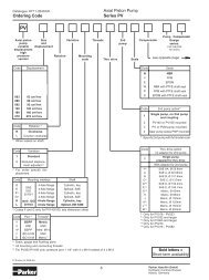
Ordering Code / Performance Curves<br />
Ordering code<br />
<strong>Proportional</strong><br />
TACS<br />
throttle valve<br />
with LVDT<br />
Code<br />
040<br />
050<br />
063<br />
080<br />
100<br />
<strong>TDL</strong>.PM6.5 RH<br />
Size<br />
NG40<br />
NG50<br />
NG63<br />
NG80<br />
NG100<br />
Size Slip-in<br />
cartridge,<br />
DIN<br />
Mounting<br />
Closed<br />
pilot circle,<br />
fast valve<br />
type,<br />
integrated<br />
electronics<br />
Sinus<br />
poppet<br />
Nominal<br />
flow<br />
5-36<br />
<strong>Proportional</strong> <strong>Throttle</strong> <strong>Valves</strong><br />
<strong>Series</strong> <strong>TDL</strong><br />
<strong>TDL</strong> E H 9 9 B 2<br />
0<br />
Code<br />
2<br />
Supply Drain<br />
external external<br />
Characteristic flow/signal line<br />
(∆p = 20/100 bar constant, viscosity 25mm2 Performance curves<br />
/s)<br />
Flow<br />
direction<br />
B → A<br />
Pilot<br />
supply<br />
Seal Electronics Standard<br />
electronics<br />
Code<br />
B<br />
E<br />
Parker Hannifin GmbH<br />
Hydraulic Controls Division<br />
Kaarst, Germany<br />
Serial<br />
letter<br />
Electronics<br />
Supply voltage<br />
0...+10V<br />
Supply<br />
0...+20mA<br />
Code Seals<br />
N NBR<br />
V FPM
Catalogue HY11-2500/UK<br />
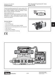
Technical Data<br />
<strong>TDL</strong>.PM6.5 RH<br />
5-37<br />
<strong>Proportional</strong> <strong>Throttle</strong> <strong>Valves</strong><br />
<strong>Series</strong> <strong>TDL</strong><br />
General<br />
Design type <strong>Throttle</strong> valve for installation into blocks with position control and integrated electronics<br />
Mounting pattern DIN ISO 7368 form A<br />
Actuation Hydraulic operation via integrated pilot control valve in the cover assembly<br />
Mounting attitude Optional: If the valve is mounted on a consumer device, the main piston/cone should not<br />
be mounted parallel to the acceleration axis.<br />
Hydraulic<br />
Pressure medium Hydraulic oil as per DIN 51 524 ... 525<br />
Viscosity, re<strong>com</strong>mended [mm²/s] 20 ... 100<br />
maximum [mm²/s] 10 ... 800<br />
Pressure medium temperature [°C] 0 ... +60<br />
Filtration Permitted contamination class of pressure medium as per NAS 1638<br />
Pilot control β x = 200 To achieve with filter:<br />
Main stage β x = 75 b x = 75<br />
Service life 8 X = 10<br />
Operating safety 9 X = 20<br />
Nominal sizes DIN NG40 NG50 NG63 NG80 NG100<br />
Weight [kg] 15 26 52 105 157<br />
Nominal flow at ∆p=20 bar [l/min] 2500 4100 6800 9500 1<strong>35</strong>00<br />
Operating pressure [bar] Ports A, B, x max. <strong>35</strong>0; Port y max. 10<br />
Flow direction B to A<br />
Pilot fluid: min [bar] 50% of the prevailing pressure<br />
Inlet from port B via X, or external X<br />
Outlet always external via Y, without pressure, max. 10 bar<br />
Leakage oil pilot control X → Y at p = 175 bar<br />
Release off [l/min] NG40 to 63
5<br />
Catalogue HY11-2500/UK<br />
Electronics<br />
Block circuit diagram electronics<br />
<strong>TDL</strong>.PM6.5 RH<br />
5-38<br />
<strong>Proportional</strong> <strong>Throttle</strong> <strong>Valves</strong><br />
<strong>Series</strong> <strong>TDL</strong><br />
Connection diagrams<br />
Electronic type B Electronic type E<br />
Connector<br />
(EMV conforming)<br />
ID no. 5004072<br />
included in the delivery scope<br />
Parker Hannifin GmbH<br />
Hydraulic Controls Division<br />
Kaarst, Germany
Catalogue HY11-2500/UK<br />
Dimensions<br />
Dimensions<br />
<strong>TDL</strong>.PM6.5 RH<br />
5-39<br />
<strong>Proportional</strong> <strong>Throttle</strong> <strong>Valves</strong><br />
<strong>Series</strong> <strong>TDL</strong><br />
Pilot valve NG50-63 Pilot valve NG40 Pilot valve NG80-100<br />
NG Bo.a. H H1 t2+0.1 a1 a2 a3 b1 b2 Ød1H7 Ød2H7 d3 d4 Ød5 Ød6 M<br />
40 275 280 90 105 50 ±0.2 23 ±0.2 42 ±0.2 62.5 210 75 55 125 85 ±0.2 max. 10 6+0.22x10 M20x45<br />
50 <strong>35</strong>5 330 130 122 58 ±0.2 30 ±0.2 50 ±0.2 70 285 90 68 140 100 ±0.2 max. 10 8+0.22x10 M20x45<br />
63 395 325 115 155 75 ±0.2 38 ±0.2 62.5 ±0.2 90 305 120 90 180 125 ±0.2 max. 12 8+0.22x10 M30x65<br />
80 410 425 80 205 - - - 125 285 145 110 250 200 ±0.2 max. 16 10+0.22x10 M24x50<br />
100 450 440 89 245 - - - 150 300 180 1<strong>35</strong> 300 245 ±0.2 max. 20 10+0.22x10 M30x51<br />
Parker Hannifin GmbH<br />
Hydraulic Controls Division<br />
Kaarst, Germany<br />
5
5<br />
Catalogue HY11-2500/UK<br />
Mounting Dimensions<br />
NG 40 to NG 63 NG 80 to NG 100<br />
* only together with d4max and t4max<br />
<strong>TDL</strong>.PM6.5 RH<br />
5-40<br />
<strong>Proportional</strong> <strong>Throttle</strong> <strong>Valves</strong><br />
<strong>Series</strong> <strong>TDL</strong><br />
Hole and mounting pattern acording ISO 7368<br />
Required minimum roughness:<br />
1 = √R<br />
16, 2 =<br />
max √ Rmax8 Nom. size b1 d1 H7 d2 H7 d3 d3 max d4 d4 max* d5 max d6 d7 H13 m1±0.2 m2±0.2 m3±0,2<br />
40 125 75 55 40 43 40 50 10 M 20 6 85 50 42.5<br />
50 140 90 68 50 56 50 63 10 M 20 8 100 58 50<br />
63 180 120 90 63 74 63 80 12 M 30 8 125 75 62.5<br />
80 250 145 110 80 93 80 100 16 M 24 10 200 - -<br />
100 300 180 1<strong>35</strong> 100 115 100 125 20 M 30 10 245 - -<br />
Nom. size m4±0.2 t1+0.1 t2+0.1 t3 t4 t4 max* t15 t6 t7 t8 t10 U W<br />
40 23 87 105 15 64 59.0 30 45 3 3 10 0.05 0.1<br />
50 30 100 122 17 72 65.5 <strong>35</strong> 45 4 3 10 0.05 0.1<br />
63 38 130 155 20 95 86.5 40 65 4 4 10 0.05 0.2<br />
80 - 175 205 25 130 120 40 50 5 5 10 0.05 0.2<br />
100 - 210 245 29 155 142 50 53 5 5 10 0.05 0.2<br />
Parker Hannifin GmbH<br />
Hydraulic Controls Division<br />
Kaarst, Germany