

Handbook of best practices
Handbook%20of%20best%20practices
Handbook%20of%20best%20practices

Create successful ePaper yourself
Turn your PDF publications into a flip-book with our unique Google optimized e-Paper software.
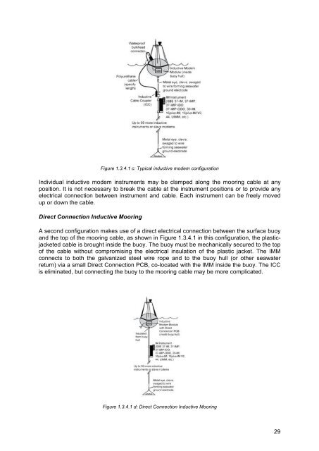
Figure 1.3.4.1 c: Typical inductive modem configuration<br />
Individual inductive modem instruments may be clamped along the mooring cable at any<br />
position. It is not necessary to break the cable at the instrument positions or to provide any<br />
electrical connection between instrument and cable. Each instrument can be freely moved<br />
up or down the cable.<br />
Direct Connection Inductive Mooring<br />
A second configuration makes use <strong>of</strong> a direct electrical connection between the surface buoy<br />
and the top <strong>of</strong> the mooring cable, as shown in Figure 1.3.4.1 in this configuration, the plasticjacketed<br />
cable is brought inside the buoy. The buoy must be mechanically secured to the top<br />
<strong>of</strong> the cable without compromising the electrical insulation <strong>of</strong> the plastic jacket. The IMM<br />
connects to both the galvanized steel wire rope and to the buoy hull (or other seawater<br />
return) via a small Direct Connection PCB, co-located with the IMM inside the buoy. The ICC<br />
is eliminated, but connecting the buoy to the mooring cable may be more complicated.<br />
Figure 1.3.4.1 d: Direct Connection Inductive Mooring<br />
29