SIMOVERT MASTERDRIVES Vector Control - MEYLE - Meyer ...
SIMOVERT MASTERDRIVES Vector Control - MEYLE - Meyer ...
SIMOVERT MASTERDRIVES Vector Control - MEYLE - Meyer ...

You also want an ePaper? Increase the reach of your titles
YUMPU automatically turns print PDFs into web optimized ePapers that Google loves.
vector control<br />
<strong>SIMOVERT</strong> <strong>MASTERDRIVES</strong> VC<br />
Single-Motor and<br />
Multi-Motor Drives<br />
0.55 kW to 2300 kW<br />
Carl-Bosch-Straße 8<br />
49525 Lengerich/Germany<br />
Tel.: +49 (0) 5481-9385-0<br />
Fax: +49 (0) 5481-9385-12<br />
Catalog DA 65.10 • 2003/2004<br />
<strong>Meyer</strong> Industrie-Electronic GmbH – <strong>MEYLE</strong><br />
Internet: www.meyle.de<br />
E-Mail: sales@meyle.de
<strong>Meyer</strong> Industrie-Electronic GmbH – <strong>MEYLE</strong><br />
Carl-Bosch-Straße 8<br />
49525 Lengerich/Germany<br />
Tel.: +49 (0) 5481-9385-0<br />
Fax: +49 (0) 5481-9385-12<br />
Configuring with PATH Plus<br />
With the PATH Plus program,<br />
three-phase drives fed by<br />
frequency converters for<br />
<strong>SIMOVERT</strong>� MASTER-<br />
DRIVES <strong>Vector</strong> <strong>Control</strong> and<br />
Motion <strong>Control</strong> units can be<br />
configured easily and quickly.<br />
The program is a powerful<br />
engineering tool which supports<br />
the user in all stages of<br />
configuration - from power<br />
supply to the motor.<br />
Internet: www.meyle.de<br />
E-Mail: sales@meyle.de<br />
Menu-guided selection and<br />
layout of the frequency converters<br />
enable the system<br />
components and the motors<br />
necessary for a specific drive<br />
task to be determined. Automatically<br />
displayed information<br />
makes fault-free planning<br />
possible.<br />
A comprehensive help system<br />
also supports the firsttime<br />
user of the program.<br />
PATH Plus provides a logical<br />
and easy-to-use dialog proce-<br />
dure to guide the planning<br />
engineer towards a reproducible<br />
and economically<br />
efficient drive configuration,<br />
starting with the mechanical<br />
requirements of the machine<br />
and the drive task involved.<br />
The technical data of the frequency<br />
converters and motors,<br />
the selected system<br />
components and the necessary<br />
accessories are listed in<br />
detail.<br />
PATH Plus enables drives to<br />
be configured on the basis of<br />
a load characteristic or a load<br />
cycle and enables planning<br />
of applications such as the<br />
following:<br />
� traversing and hoisting<br />
gear,<br />
� slewing gear,<br />
� spindle drives,<br />
� center winders and<br />
� thrust crank.<br />
PATH Plus also includes a<br />
comfortable graphic display<br />
for showing<br />
� torque, speed, output,<br />
current, velocity and acceleration<br />
versus time and<br />
� torque versus rotational<br />
speed.<br />
Supply harmonic disturbances<br />
can also be calculated and<br />
graphically displayed.<br />
The planning and configuring<br />
results can be stored, printed<br />
out or copied to other user<br />
programs via the clipboard.<br />
PATH Plus is available with<br />
either a German or English<br />
user interface.<br />
You can download the demo<br />
version of PATH Plus from<br />
the following Internet address:<br />
http://www.siemens.com/<br />
motioncontrol<br />
(products&systems/drive<br />
systems/software)<br />
or use the fax form attached<br />
to the catalog.<br />
If you need the full version of<br />
PATH Plus, contact your local<br />
Siemens office and quote<br />
the following order number:<br />
6SW1710-0JA00-2FC0<br />
You will find the address in<br />
the appendix to this catalog.
<strong>SIMOVERT</strong><br />
<strong>MASTERDRIVES</strong><br />
<strong>Vector</strong> <strong>Control</strong><br />
0.55 kW to 2300 kW<br />
Catalog DA 65.10<br />
2003/2004<br />
Supersedes:<br />
Catalog DA 65.10 · 2001<br />
The products in this catalog<br />
are also included in the<br />
CD-ROM catalog CA 01<br />
Order No.:<br />
E86060-D4001-A100-B9-7600<br />
Contact your local Siemens<br />
representative for further<br />
information.<br />
The products and<br />
systems described in<br />
this catalog are manufactured<br />
under application<br />
of a quality<br />
management system<br />
certified by DQS in<br />
accordance with<br />
DIN EN ISO 9001 and<br />
DIN EN ISO 14001.<br />
The DQS Certificate is<br />
recognized in all EQ Net<br />
countries.<br />
s<br />
Selection and Ordering Data<br />
Overview<br />
System Description<br />
6SE70 Compact PLUS Units<br />
6SE70 Compact and Chassis Units<br />
6SE71 Cabinet Units<br />
Documentation and Training<br />
Engineering Information<br />
Dimension Drawings<br />
Appendix · Index<br />
<strong>Meyer</strong> Industrie-Electronic GmbH – <strong>MEYLE</strong><br />
Carl-Bosch-Straße 8<br />
49525 Lengerich/Germany<br />
Tel.: +49 (0) 5481-9385-0<br />
Fax: +49 (0) 5481-9385-12<br />
Internet: www.meyle.de<br />
E-Mail: sales@meyle.de<br />
1<br />
2<br />
3<br />
4<br />
5<br />
6<br />
7<br />
A
Note!<br />
The technical data is intended for general information.<br />
Please observe the operating instructions and the references indicated on the products for installation, operation and<br />
maintenance.<br />
� SIMADYN, SIMATIC, SIMATIC HMI, SIMODRIVE, SIMOLINK, SIMOREG, <strong>SIMOVERT</strong>, SITOR, STEP, STRUC and USS are<br />
Siemens registered trademarks.<br />
All other products and system names in this catalog are (registered) trademarks of their respective owners and must be<br />
treated accordingly.<br />
� The technical data, selection and ordering data (Order Nos.), accessories and availability are subject to alteration.<br />
� All dimensions in this catalog are stated in mm.<br />
� Siemens AG 2003
<strong>Vector</strong> <strong>Control</strong><br />
Overview<br />
1/2 Application<br />
List of contents<br />
1/4 Unit and system components<br />
1/6 Electronic and software options<br />
Order number examples<br />
1/8 Compact PLUS units<br />
Compact and chassis units<br />
1/8 Cabinet units<br />
Siemens DA 65.10 · 2003/2004<br />
1/1<br />
1
1<br />
<strong>SIMOVERT</strong>r <strong>MASTERDRIVES</strong> <strong>Vector</strong> <strong>Control</strong><br />
Overview<br />
Applications<br />
Top solutions with<br />
engineered drives<br />
The <strong>SIMOVERT</strong> MASTER-<br />
DRIVES <strong>Vector</strong> <strong>Control</strong><br />
frequency converters are<br />
voltage-source DC link<br />
converters with fully digital<br />
technology and IGBT inverters<br />
which, in conjunction<br />
with Siemens three phase<br />
AC motors, provide highperformance,<br />
economical<br />
drives for all industrial sectors<br />
and applications.<br />
<strong>SIMOVERT</strong> <strong>MASTERDRIVES</strong><br />
– system-based drive<br />
technology<br />
A uniform, modular series<br />
of standard units<br />
The <strong>SIMOVERT</strong> MASTER-<br />
DRIVES <strong>Vector</strong> <strong>Control</strong><br />
series of converters is both<br />
uniform and modular in design.<br />
Á The power output of the<br />
standard units ranges from<br />
0.55 kW to 2300 kW.<br />
Á All internationally standard<br />
supply voltages from 380 V<br />
to 690 V are covered.<br />
1/2<br />
Siemens DA 65.10 × 2003/2004<br />
Á Depending on the application<br />
and the required<br />
output, there are four types<br />
of housing design available:<br />
the Compact PLUS<br />
unit, the compact unit, the<br />
chassis unit and the cabinet<br />
unit.<br />
Á The hardware and software<br />
modules enable tailored<br />
and cost effective drive<br />
solutions.<br />
As a counterpart to extremely<br />
high-performance<br />
VC control on the motor<br />
side, the <strong>SIMOVERT</strong><br />
<strong>MASTERDRIVES</strong> AFE (Active<br />
Front End) unit ensures<br />
optimum energy supply on<br />
the line side as well with its<br />
active, line-angle-oriented<br />
vector control. <strong>SIMOVERT</strong><br />
<strong>MASTERDRIVES</strong> AFE units<br />
are characterized by<br />
Á freedom from system perturbations,<br />
i.e. a very favorable<br />
overall power factor<br />
Á commutation failure-protected<br />
operation even in<br />
the event of supply dips<br />
and power failure<br />
Compact PLUS/compact and<br />
chassis units · cabinet units<br />
Á the possibility of reactive<br />
power compensation<br />
Á four-quadrant operation.<br />
The units are designed as:<br />
Á converters for connection<br />
to a 3-phase AC system<br />
Á inverters for connection to<br />
a DC bus<br />
Á rectifier units for supplying<br />
power to the DC bus.<br />
A wide spectrum of system<br />
components and accessories<br />
rounds off the range of<br />
products.<br />
<strong>SIMOVERT</strong> <strong>MASTERDRIVES</strong><br />
The tailored solution<br />
All <strong>SIMOVERT</strong> MASTER-<br />
DRIVES share a consistently<br />
uniform design.Throughout<br />
the whole power range, the<br />
units (converters, inverters)<br />
and system components<br />
(rectifier units, braking units)<br />
have a uniform design and a<br />
uniform connection system.<br />
They can be combined in<br />
many ways and arranged<br />
side by side to match every<br />
possible drive requirement.<br />
Being system modules, they<br />
can be used to create the<br />
most suitable drive system,<br />
whether this involves single<br />
drives or multi-motor drives.<br />
Customer-specific solutions<br />
Cabinets and system<br />
configurations for power<br />
output ranges from 0.55 kW<br />
to 6000 kW can be created<br />
to match specific customer<br />
requirements, with either aircooling<br />
or water-cooling in<br />
our application workshop.<br />
Examples of such applications<br />
are<br />
Á multi-motor drives (steelworks<br />
and rolling mills,<br />
the paper and plastic-film<br />
industries) and<br />
Á single drives<br />
– in adapted design<br />
(e.g. marine drives)<br />
– for test stands (e.g. with<br />
Active Front End for low<br />
supply stressing).
<strong>SIMOVERT</strong> <strong>MASTERDRIVES</strong><br />
with water-cooling – for<br />
harsh environments<br />
The compact and chassis<br />
converters and inverters are<br />
also available with watercooling.<br />
By installing in<br />
appropriate cabinets, high<br />
degrees of protection are<br />
achieved in a closed system,<br />
thus making them suitable<br />
for use in any harsh industrial<br />
environment.<br />
New!<br />
The Compact PLUS series<br />
The youngest member of<br />
the <strong>SIMOVERT</strong> MASTER-<br />
DRIVES <strong>Vector</strong> <strong>Control</strong> family<br />
with power outputs of<br />
0.55 kW to 18.5 kW rounds<br />
off the product range in the<br />
lower power output range.<br />
The Compact PLUS series is<br />
ideal for applications in machines<br />
where only limited<br />
space is available.<br />
Compact PLUS/compact and<br />
chassis units · cabinet units<br />
<strong>SIMOVERT</strong> <strong>MASTERDRIVES</strong> <strong>Vector</strong> <strong>Control</strong><br />
Overview<br />
<strong>SIMOVERT</strong> <strong>MASTERDRIVES</strong><br />
– electromagnetically<br />
compatible in any environment<br />
The <strong>SIMOVERT</strong> MASTER-<br />
DRIVES frequency converters<br />
comply with the relevant<br />
EMC standard for power<br />
electronics.<br />
EMC compliant installation<br />
enables them to be used in<br />
industry and residential<br />
buildings.<br />
Designed for world-wide<br />
use<br />
The <strong>SIMOVERT</strong> MASTER-<br />
DRIVES satisfy the relevant<br />
international standards and<br />
regulations – from the<br />
European EN standard and<br />
IEC to UL and CSA.<br />
Applications<br />
Quality in accordance with<br />
DIN ISO 9001<br />
The quality standards<br />
according to which the<br />
<strong>SIMOVERT</strong> MASTER-<br />
DRIVES are manufactured<br />
are high and have been<br />
acclaimed. All aspects of<br />
production, i.e. development,<br />
mechanical design,<br />
manufacturing, order processing<br />
and the logistics<br />
supply center of the<br />
<strong>SIMOVERT</strong> MASTER-<br />
DRIVES, have been certified<br />
by an independent authority<br />
in accordance with<br />
DIN ISO 9001.<br />
Engineering technology<br />
with maximum benefit to<br />
the customer<br />
The advantages to the<br />
customer are apparent:<br />
Á solutions, optimized with<br />
regard to price and performance<br />
Á high quality,<br />
Á maximum reliability<br />
and as a result<br />
Á flexible production and<br />
Á optimized processes.<br />
Our world-wide service and<br />
sales network provides all<br />
our customers and<br />
<strong>SIMOVERT</strong> MASTER-<br />
DRIVES users with a<br />
direct line to:<br />
Á individual advice<br />
Á planning<br />
Á training and<br />
Á service.<br />
Siemens DA 65.10 × 2003/2004 1/3<br />
1
1<br />
<strong>SIMOVERT</strong> <strong>MASTERDRIVES</strong> <strong>Vector</strong> <strong>Control</strong><br />
Overview<br />
Applications<br />
List of contents<br />
Unit and system components<br />
1/2 1/4<br />
Converters and Inverters<br />
Rectifier units<br />
Braking units and braking resistors<br />
Line-side switching and protection components<br />
DC link components<br />
Load-side components<br />
Siemens DA 65.10 × 2003/2004<br />
Compact PLUS/compact and<br />
chassis units · cabinet units
Compact PLUS/compact and<br />
chassis units · cabinet units<br />
<strong>SIMOVERT</strong> <strong>MASTERDRIVES</strong> <strong>Vector</strong> <strong>Control</strong><br />
Overview<br />
List Applications<br />
of contents<br />
Technical Selection and Engineering Dimension<br />
characteristics ordering data information drawings<br />
Page Page Page Page<br />
Compact PLUS units 3/4 3/6 6/2 7/2<br />
Compact and chassis units 3/8 3/10 6/2 7/3<br />
Water-cooled converters 3/18 3/20 6/4 7/3<br />
Converter cabinets 4/4 4/6 6/2 7/23<br />
Self-commutating, pulsed<br />
rectifier/regenerative units<br />
Active Front End AFE 3/24 3/26 6/23 7/3<br />
Rectifier units 3/28 3/30 6/14 7/2<br />
Rectifier/regenerative units 3/28 3/32 6/17 7/6<br />
Braking units and<br />
Braking resistors 3/38 3/40 6/49 7/9<br />
Line fuses 3/42 3/47 6/47 –<br />
Line commutating reactors 3/42 3/47 6/47 7/11<br />
Autotransformers 3/42 3/73 6/47 7/13<br />
Radio-interference<br />
suppression filters 3/42 3/47 6/47 7/15<br />
Overcurrent Protector units (OCP) 3/36 3/37 6/21 7/8<br />
Fuse switch disconnectors 3/43 3/46 6/48 –<br />
Fuses 3/43 3/56 6/48 –<br />
Precharging resistors 3/43 3/57 6/48 7/18<br />
Precharging contactor/<br />
connecting contactor 3/43 3/57 6/48 –<br />
Free-wheeling diodes 3/43 3/57 6/48 –<br />
Output reactors 3/43 3/50 6/50 7/19<br />
Output sine filters 3/43 3/50 6/52 7/21<br />
Voltage limitation filters 3/43 3/51 6/51 7/21<br />
Motor connecting cables 3/44 3/80 6/50 –<br />
Siemens DA 65.10 × 2003/2004 1/3 1/5<br />
1
1<br />
<strong>SIMOVERT</strong> <strong>MASTERDRIVES</strong> <strong>Vector</strong> <strong>Control</strong><br />
Overview<br />
Applications<br />
List of contents<br />
Electronic and software options<br />
1/2 1/6<br />
Operator control and visualization<br />
<strong>Control</strong><br />
Communication<br />
Interface and expansion boards<br />
Technology boards<br />
Integration of option boards<br />
Siemens DA 65.10 × 2003/2004<br />
Compact PLUS/compact and<br />
chassis units · cabinet units
Compact PLUS/compact and<br />
chassis units · cabinet units<br />
<strong>SIMOVERT</strong> <strong>MASTERDRIVES</strong> <strong>Vector</strong> <strong>Control</strong><br />
Overview<br />
Technical Selection and Engineering<br />
characteristics ordering data information<br />
Page Page Page<br />
Communication with SIMATICr 2/13 3/92 6/56<br />
Drive ES<br />
Start up, parameterization and diagnostics<br />
2/13 3/91 –<br />
with DriveMonitorr 2/10 3/92 –<br />
Operator control and visualization 2/6 – –<br />
PMU operator control and parameterizing unit 2/7 3/90 –<br />
OP1S user-friendly operator control panel 2/8 3/90 –<br />
External 24 V voltage supply and main<br />
contactor control 2/9 – 6/15<br />
<strong>Control</strong> terminal strips of the CUVC boards 2/9 – 6/35<br />
Open-loop and closed-loop control functions 2/3 – 6/28<br />
Software functions 2/3 – 6/32<br />
Free function blocks with the BICO system 2/3 – 6/33<br />
Safe Stop – – 6/33<br />
Communication 2/4 – 6/54<br />
Serial interfaces of the basic units 2/4 – 6/54<br />
CBP/CBP2 communication board for<br />
Motion <strong>Control</strong> with PROFIBUS DP 2/5 3/85 6/57<br />
CBC communication board for CAN 2/5 3/85 6/59<br />
SLB communication board for SIMOLINKr 2/5 3/85 6/61<br />
SCB1 interface board 3/89 3/89 6/80<br />
SCB2 interface board 3/89 3/89 6/80<br />
SCI1 and SCI2 interface boards 3/89 3/89 6/82<br />
DTI digital tachometer interface 3/89 3/89 6/85<br />
SBP incremental encoder board 3/86 3/86 6/67<br />
VSB voltage sensing interface 3/89 3/89 –<br />
EB1 expansion board 3/86 3/86 6/63<br />
EB2 expansion board 3/86 3/86 6/65<br />
T100 technology board 3/87 3/87 6/69<br />
T300 technology board 3/87 3/88 6/72<br />
T400 technology board – – 6/79<br />
TSY synchronisation board 3/89 3/89 6/84<br />
Compact PLUS units – 6/53 6/53<br />
Compact and chassis units – – 6/55<br />
Bus adapter for the electronics box LBA 3/87 3/87 6/54<br />
ADB adapter board 3/87 3/87 6/54<br />
List Applications<br />
of contents<br />
Siemens DA 65.10 × 2003/2004 1/3 1/7<br />
1
1<br />
Overview<br />
Order number examples<br />
Compact PLUS units, compact and chassis units<br />
<strong>SIMOVERT</strong> <strong>MASTERDRIVES</strong> 6SE7 series<br />
Compact PLUS units, compact units, chassis units<br />
Multiplier for output current<br />
e.g.: 2 ×1<br />
3 ×10<br />
4 × 100<br />
First two positions for output current<br />
Supply voltage code e.g. E 3AC380V–480V<br />
Size e.g. chassis size E<br />
<strong>Control</strong> version 6 <strong>SIMOVERT</strong> <strong>MASTERDRIVES</strong> <strong>Vector</strong> <strong>Control</strong><br />
Function release<br />
Supplementary order codes for options<br />
Cabinet units<br />
<strong>SIMOVERT</strong> <strong>MASTERDRIVES</strong> 6SE7 series<br />
Cabinet units<br />
Multiplier for output current<br />
e.g.: 2 ×1<br />
3 ×10<br />
4 × 100<br />
First two positions for output current<br />
Supply voltage code e.g. F 3AC500V–600V<br />
Size e.g. Cabinet size D, width 1200 mm<br />
<strong>Control</strong> version 6 <strong>SIMOVERT</strong> <strong>MASTERDRIVES</strong> <strong>Vector</strong> <strong>Control</strong><br />
Mechanical version e.g. 1 size, chassis units E to G<br />
Electrical version e.g. 3 converter, single-quadrant<br />
Function release<br />
Supplementary order codes for options<br />
1/8<br />
<strong>SIMOVERT</strong> <strong>MASTERDRIVES</strong> <strong>Vector</strong> <strong>Control</strong><br />
Siemens DA 65.10 · 2003/2004<br />
Example:<br />
Multiplier = 10<br />
First two positions of output current: 10<br />
Output current rounded off = 100 A<br />
Example:<br />
Multiplier = 10<br />
First two positions of output current: 16<br />
Output current rounded off = 160 A<br />
Compact PLUS/compact and<br />
chassis units · cabinet units<br />
e.g. 6SE7031–0EE60–Z<br />
e.g. 6SE7131–6FD61–3BA0–Z
<strong>Vector</strong> <strong>Control</strong><br />
System<br />
Description<br />
System layout<br />
2/2 Converters and inverters<br />
2/2 Rectifier units and rectifier/regenerative units<br />
2/3 Self-commutating, pulsed rectifier/<br />
2/3<br />
2/3<br />
regenerative units Active Front End AFE<br />
System components<br />
Overcurrent protector units (OCP)<br />
<strong>Control</strong> functions<br />
2/3 <strong>Control</strong> types<br />
2/3 Software functions<br />
2/3 Free function blocks<br />
Communication via serial interfaces<br />
2/4 Interfaces on the base units<br />
2/5 Options: communication and<br />
interface boards<br />
2/5 Transfer protocols and fieldbus systems<br />
Operator control and visualization<br />
2/7 PMU operator control and parameterizing unit<br />
2/8 OP1S user-friendly operator control panel<br />
2/9 <strong>Control</strong> terminal strip<br />
2/9 External 24 V voltage supply and main<br />
contactor control<br />
2/10 Start-up,parameterization and diagnostics<br />
with DriveMonitor<br />
<strong>SIMOVERT</strong> <strong>MASTERDRIVES</strong> in the world<br />
of automation<br />
2/11 Link-up to automation systems<br />
2/12 Integrating drives in SIMATIC S5<br />
2/13 Integrating drives in SIMATIC S7<br />
with Drive ES<br />
2/14 Configuration program Drive ES<br />
Siemens DA 65.10 · 2003/2004<br />
2/1<br />
2
2<br />
2/2<br />
<strong>SIMOVERT</strong> <strong>MASTERDRIVES</strong> <strong>Vector</strong> <strong>Control</strong><br />
System Description<br />
System layout<br />
<strong>SIMOVERT</strong> <strong>MASTERDRIVES</strong> converters<br />
The <strong>SIMOVERT</strong> MASTER-<br />
DRIVES <strong>Vector</strong> <strong>Control</strong> series<br />
of converters consists of<br />
modular, high-performance<br />
components. These components<br />
can be combined for<br />
individual applications.<br />
Converters and inverters<br />
The <strong>SIMOVERT</strong> MASTER-<br />
DRIVES are available as:<br />
� converters for connection<br />
to a 3-phase AC system.<br />
� inverters for connection to<br />
DC buses which are supplied<br />
with power by rectifier<br />
or rectifier/regenerative<br />
units.<br />
The system of components<br />
enables a uniform layout,<br />
irrespective of whether<br />
converters or inverters are<br />
used. The components can<br />
be installed side by side in almost<br />
any combination, even<br />
if they are different in size,<br />
enabling considerable space<br />
savings to be made.<br />
As system modules, they<br />
can be used to obtain the<br />
right solution to match any<br />
drive task, whether single or<br />
multi-motor.<br />
The <strong>SIMOVERT</strong> MASTER-<br />
DRIVES converter series<br />
covers a power output ranging<br />
from 0.55 kW to<br />
DA65-5282c<br />
Siemens DA 65.10 · 2003/2004<br />
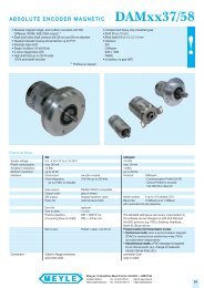
2300 kW (see Fig. 2/1),<br />
application cabinets up to<br />
6000 kW.<br />
The units have a uniform<br />
connection system: the linevoltage<br />
and DC link terminals<br />
are located on top and the<br />
motor terminals at the<br />
bottom.<br />
The modular and uniform<br />
design of the electronic<br />
options enables optimized<br />
matching to all drive requirements<br />
with regard to both<br />
technology and communication.<br />
Easy handling and installation<br />
and a high level of<br />
uniformity were essential<br />
factors in the development<br />
of the <strong>SIMOVERT</strong> MASTER-<br />
DRIVES. This is demonstrated<br />
by the standardized<br />
housings, mounting and connection<br />
levels, as well as by<br />
the connections to signal<br />
and bus cables.<br />
The <strong>SIMOVERT</strong> MASTER-<br />
DRIVES are available as Compact<br />
PLUS units, compact<br />
units, chassis units and as cabinet<br />
units.<br />
� Compact PLUS units are<br />
the specialists for limited<br />
space conditions. The<br />
“BOOKSIZE”format in<br />
IP20 degree of protection<br />
and the ideal connection<br />
3-ph. AC 500V–600V<br />
DC 675 V – 810 V<br />
3-ph. AC 380V–480V<br />
DC 510 V – 650 V<br />
Compact units<br />
3-ph. AC 380V–480V<br />
DC 510 V – 650 V<br />
Compact PLUS units<br />
18.5 kW<br />
30 kW<br />
37 kW<br />
Compact PLUS/compact and<br />
chassis units · cabinet units<br />
system of the units makes<br />
the design of extremely<br />
compact multi-motor drives<br />
possible. Compact PLUS<br />
units can be mounted into<br />
300 mm deep cabinets.<br />
� Compact units are designed<br />
in the space-saving<br />
“BOOKSIZE”format with<br />
IP20 degree of protection .<br />
The units are simply hung<br />
from a standard DIN G rail<br />
and secured at the bottom<br />
of the cabinet with a screw<br />
fastening. Compact units<br />
can be mounted into<br />
� 400 mm deep cabinets.<br />
� Chassis units are designed<br />
with IP00 degree of protection.<br />
The covers conform<br />
with the safety regulations<br />
to DIN VDE 0113, Part 5 and<br />
DIN VDE 0106, Part 100<br />
(VBG 4). IP20 degree of<br />
protection can also be<br />
achieved with an optional<br />
enclosure kit.<br />
The Compact PLUS units as<br />
well as the compact and<br />
chassis units can be installed<br />
without any space between<br />
them.<br />
� Cabinet units are supplied<br />
as converters with IP20 degree<br />
of protection as standard.<br />
Cabinets with higher<br />
degrees of protection are<br />
also available (see Sec-<br />
55 kW<br />
3-ph. AC 660V–690V<br />
DC 890 V – 930 V<br />
37 kW<br />
3-ph. AC 500V–600V<br />
DC 675 V – 810 V<br />
45 kW<br />
3-ph. AC 380V–480V<br />
DC 510 V – 650 V<br />
Chassis units/cabinet units<br />
tion 4). The converter cabinet<br />
units are ready-to-connect<br />
cabinets for single and<br />
group drives with options<br />
available for every possible<br />
application.<br />
Designs available:<br />
� Single-quadrant operation,<br />
6/12 pulse, line-commutated<br />
� Four-quadrant operation,<br />
6-pulse, line-commutated<br />
� Four-quadrant operation,<br />
self-commutated with<br />
Active Front End.<br />
Rectifier units and<br />
rectifier/regenerative<br />
units<br />
Types of DC voltage supply<br />
units<br />
There are two types of DC<br />
supply units for supplying<br />
one or more inverters:<br />
� The rectifier unit is a<br />
6-pulse rectifier bridge with<br />
pre-charging circuit and<br />
enables the flow of energy<br />
from the power system to<br />
the DC voltage bus (single-quadrant<br />
operation).<br />
1300 kW<br />
1700 kW<br />
2300 kW<br />
0,55<br />
Fig. 2/1<br />
2,2 10 100 1000 2300<br />
Output power range of <strong>SIMOVERT</strong> <strong>MASTERDRIVES</strong> <strong>Vector</strong> <strong>Control</strong>
� The rectifier/regenerative<br />
unit consists of two antiparallel<br />
6-pulse thyristor<br />
bridges and enables the<br />
flow of energy in both<br />
directions, i.e. energy can<br />
be fed back into the power<br />
system (4-quadrant operation).<br />
The regenerating<br />
bridge is connected via an<br />
autotransformer (option).<br />
12-pulse operation<br />
Converters for 12-pulse<br />
operation are supplied by<br />
two parallel-connected rectifier<br />
or rectifier/regenerative<br />
units with the same output<br />
rating.<br />
They are connected to the<br />
supply via a three-winding<br />
transformer with two secondary<br />
windings electrically<br />
displaced by 30 °. In this way,<br />
system perturbations are<br />
considerably reduced. The<br />
relevant harmonic currents<br />
of the fifth and seventh order<br />
are almost eliminated when<br />
compared to 6-pulse operation.<br />
Optimum power infeed is ensured<br />
by the self-commutating,<br />
pulsed rectifier/regener-<br />
<strong>Control</strong> functions<br />
<strong>Control</strong> types<br />
The <strong>SIMOVERT</strong> MASTER-<br />
DRIVES <strong>Vector</strong> <strong>Control</strong> standard<br />
software contains two<br />
principal control types:<br />
� Frequency control by<br />
means of the V/f-characteristic<br />
curve<br />
with or without speed<br />
feedback and for textile<br />
applications. Frequency<br />
control is suitable for simple<br />
applications and for high<br />
level synchronism within<br />
group drives.<br />
� <strong>Vector</strong> control (fieldoriented<br />
control)<br />
for dynamic applications in<br />
the form of frequency<br />
control (without encoder)<br />
or speed/torque control<br />
(with encoder). The vector<br />
control method achieves a<br />
dynamic performance<br />
which is comparable to that<br />
of a DC drive. This is based<br />
on precise modeling of the<br />
Compact PLUS/compact and<br />
chassis units · cabinet units<br />
<strong>SIMOVERT</strong> <strong>MASTERDRIVES</strong> <strong>Vector</strong> <strong>Control</strong><br />
ative AFE (Active Front End)<br />
unit. Its core components are<br />
an inverter with a CUSA control<br />
unit and it generates a<br />
regulated DC voltage from a<br />
three-phase supply. On the<br />
three-phase side, rapid vector<br />
control subordinate to<br />
this DC voltage control impresses<br />
an almost sinusoidal<br />
current towards the supply<br />
so that, with the help of the<br />
line-side clean power filter,<br />
system perturbations are<br />
kept to a minimum. <strong>Vector</strong><br />
control also enables power<br />
factor (cos �) setting and<br />
enabling reactive power<br />
compensation as well,<br />
whereby the drive's power<br />
requirement has priority. A<br />
bigger advantage is that, due<br />
to the underlying principle of<br />
this method, inverter stalling<br />
with fuse tripping cannot occur<br />
when there is a power<br />
failure, even during regenerative<br />
operation.<br />
Single-quadrant operation,<br />
four-quadrant operation<br />
Units for single-quadrant<br />
operation can only work in<br />
motoring mode. For regenerative<br />
mode, a braking unit/<br />
motor and two current<br />
components which influence<br />
the flux and the<br />
torque with a control frequency<br />
of 2.5 kHz. Using<br />
this vector control method,<br />
torque setpoints can be<br />
held and limited.<br />
In the 1:10 speed range,<br />
the field-oriented control<br />
system of <strong>SIMOVERT</strong><br />
<strong>MASTERDRIVES</strong> <strong>Vector</strong><br />
<strong>Control</strong> does not require a<br />
speed encoder and is<br />
largely independent of<br />
motor parameters.<br />
The following uses of<br />
<strong>SIMOVERT</strong> MASTER-<br />
DRIVES <strong>Vector</strong> <strong>Control</strong> require<br />
a speed encoder:<br />
� High dynamic performance<br />
requirements<br />
� Torque control in the control<br />
range > 1:10<br />
� Low speeds<br />
braking resistor is necessary.<br />
Units for four-quadrant operation<br />
can return regenerative<br />
energy to the three-phase<br />
supply. This may be necessary,<br />
for example, when<br />
drives with a large rotating<br />
mass have to be braked frequently<br />
or rapidly.<br />
System components<br />
In addition to the converter,<br />
inverter and rectifier basic<br />
units, the system components<br />
enable tailor-made<br />
solutions to meet the drive<br />
requirements.<br />
The system components can<br />
be broken down as follows:<br />
� Overcurrent protector units<br />
(OCP) for rectifier/regenerative<br />
units<br />
In the case of line-commutating<br />
rectifier/regenerative<br />
units, the occurrence of<br />
undervoltages or voltage<br />
dips can cause the inverter<br />
to stall and the fuse to trip<br />
during regenerative mode.<br />
This can mean that the<br />
equipment may have to be<br />
shut down for a longer period.<br />
� Maximum speed accuracy.<br />
The different types of control<br />
are described in detail in Section<br />
6.<br />
Software functions<br />
The basic software contains<br />
a wide range of standard<br />
functions. These functions<br />
provide maximum userfriendliness<br />
regarding operator<br />
control and the highest<br />
degree of flexibility (setpoint<br />
selection, changeover between<br />
data sets, etc.). They<br />
also ensure universal operating<br />
conditions and a high<br />
level of operational safety<br />
(automatic restart, flying<br />
restart, DC injection braking,<br />
synchronization between<br />
converters, wobble generator,<br />
motor brake control,<br />
etc.).<br />
These functions are<br />
described in Section 6.<br />
System Description<br />
In order to avoid this, the<br />
overcurrent protector unit<br />
(OCP) can be used in<br />
combination with the linecommutatedrectifier/regenerative<br />
unit (R/R unit)<br />
for four-quadrant operation.<br />
It prevents fuse tripping by<br />
triggering an IGBT in the<br />
DC link so that the IGBT<br />
cuts off the power. This is<br />
of particular advantage in<br />
the case of large group<br />
drives.<br />
As soon as the fault has<br />
been acknowledged, the<br />
equipment is ready for operation.<br />
� Braking units and braking<br />
resistors<br />
� Electronic options e.g.<br />
technology, communication<br />
and interface boards<br />
� Other system components<br />
such as<br />
switching and protection<br />
devices,<br />
line reactors and output<br />
reactors and<br />
radio interference suppression<br />
filters.<br />
Free function blocks<br />
Using the free function<br />
blocks contained in the basic<br />
software, the drives can be<br />
adapted to the most varied<br />
of applications. Simple<br />
control systems can thus<br />
be created and technology<br />
requirements can be dealt<br />
with in a decentralized manner.<br />
The function blocks available<br />
in <strong>SIMOVERT</strong> MASTER-<br />
DRIVES <strong>Vector</strong> <strong>Control</strong> can<br />
be classified as follows:<br />
� <strong>Control</strong> blocks<br />
� Signal conversion blocks<br />
� Computing blocks<br />
� Logic blocks<br />
� Signalling blocks<br />
� Timers.<br />
For a detailed description,<br />
see Section 6.<br />
Siemens DA 65.10 · 2003/2004<br />
System layout<br />
2/3<br />
2
2<br />
2/4<br />
<strong>SIMOVERT</strong> <strong>MASTERDRIVES</strong> <strong>Vector</strong> <strong>Control</strong><br />
System Description<br />
Communication via serial interfaces<br />
<strong>MASTERDRIVES</strong><br />
Basic unit<br />
COM1 COM2<br />
USS protocol<br />
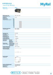
Fig. 2/2<br />
Overview of interfaces<br />
Communication via<br />
serial interfaces<br />
Siemens DA 65.10 · 2003/2004<br />
DPRAM<br />
X9<br />
2 )<br />
2 )<br />
1 )<br />
1 )<br />
2 )<br />
CBP2<br />
CBC<br />
T400<br />
T300<br />
T100<br />
SCB2<br />
SLB<br />
DC<br />
24 V<br />
External 24 V DC<br />
power supply (communication<br />
also possible when power<br />
section is switched off)<br />
Options<br />
PROFIBUS DP<br />
CAN<br />
USS<br />
protocol<br />
SIMOLINK<br />
Compact PLUS/compact and<br />
chassis units · cabinet units<br />
V supply<br />
peer-to-peer<br />
1) Not available for Compact PLUS units.<br />
2) Only two option boards may be used at one time<br />
with the Compact PLUS units.<br />
ADA65-5283d<br />
The <strong>SIMOVERT</strong> MASTER-<br />
DRIVES <strong>Vector</strong> <strong>Control</strong> units<br />
have several serial interfaces<br />
for communicating with, e.g.<br />
higher-level PLC systems,<br />
PCs etc. The interfaces can<br />
be classified as follows:<br />
� Basic version:<br />
Two serial interfaces,<br />
COM1 and COM2, as standard<br />
on the basic unit<br />
� Options:<br />
Communication and interface<br />
boards for different<br />
transmission protocols or<br />
bus systems.<br />
Interfaces on the basic unit<br />
Compact and chassis units<br />
� Serial interface 1 (COM1) is<br />
located on the PMU operator<br />
control and parameterizing<br />
unit. It is a 9-pole SUB D<br />
socket (X300) as an RS485<br />
or RS232 interface (see<br />
page 2/7).<br />
� Serial interface 2 (COM2) is<br />
located on the X101 control<br />
terminal strip of the CUVC<br />
board as an RS485 interface<br />
(see page 2/8).<br />
Compact PLUS units<br />
COM1 and COM2 are connected<br />
to the X103 SUB-D<br />
socket. COM2 is also connected<br />
to the X100 connector.<br />
COM1 is designed as an<br />
RS232 interface and COM2<br />
is designed as an RS485 interface.<br />
Both serial interfaces of the<br />
basic unit work with the<br />
USSr protocol, are bus-capable<br />
(with up to 31 nodes) and<br />
enable maximum data transfer<br />
rates of 38.4 kbit/s.<br />
USS protocol<br />
The USS protocol is a<br />
Siemens-specific transmission<br />
protocol for drive technology<br />
and is implemented<br />
as a standard protocol on all<br />
interfaces of the basic units.<br />
The USS protocol enables<br />
bus operation of up to a<br />
maximum of 32 nodes on<br />
the basis of the RS485 transmission<br />
system.
Data is exchanged in accordance<br />
with the master-slave<br />
access procedure. The USS<br />
protocol only allows monomaster<br />
operation. This<br />
means one master and 31<br />
slaves. Masters can be<br />
higher-level systems such as<br />
the SIMATIC S5, S7 and PCs<br />
or non-Siemens automation<br />
systems. <strong>SIMOVERT</strong><br />
<strong>MASTERDRIVES</strong> are always<br />
slaves.<br />
From an application point of<br />
view, the USS protocol is<br />
used for the following two<br />
applications:<br />
– Data transmission between<br />
a PC and one or<br />
several <strong>MASTERDRIVES</strong><br />
for start-up and parameterization<br />
of the units<br />
using the Drive ES and<br />
DriveMonitor engineering<br />
tools. The user-friendly<br />
operator control panel<br />
OP1S also communicates<br />
to the <strong>SIMOVERT</strong><br />
<strong>MASTERDRIVES</strong> using of<br />
the USS protocol. COM1<br />
is used for linking up to the<br />
PC or the OP1S.<br />
– Communication via the<br />
USS protocol to higherlevel<br />
automation systems<br />
such as the SIMATIC S5,<br />
SIMATIC S7 or to non-<br />
Siemens systems. For this<br />
link, COM2 is usually<br />
used.<br />
Parallel operation of COM1<br />
and COM2 is possible without<br />
any restrictions.<br />
See also documentation:<br />
“<strong>SIMOVERT</strong> MASTER-<br />
DRIVES, Anwendung der<br />
seriellen Schnittstellen<br />
mit USS-Protokoll”,<br />
Order No.:<br />
6SE7087-6CX87-4KB0.<br />
This documentation is available<br />
in German only.<br />
Compact PLUS/compact and<br />
chassis units · cabinet units<br />
<strong>SIMOVERT</strong> <strong>MASTERDRIVES</strong> <strong>Vector</strong> <strong>Control</strong><br />
Options:<br />
Communication and<br />
interface boards<br />
The PROFIBUS DP and CAN<br />
serial fieldbus systems can<br />
be linked up by means of the<br />
communication boards,<br />
CBP (Communication Board<br />
PROFIBUS DP) or CBC<br />
(Communication Board CAN).<br />
Fast data exchange between<br />
the <strong>MASTERDRIVES</strong> units is<br />
possible by means of the<br />
SLB (SIMOLINK Board) communication<br />
board.<br />
In addition to this, the SCB1<br />
and SCB2 interface boards<br />
(Serial Communication<br />
Board) are available for the<br />
USS protocol and peer-topeer<br />
protocol.<br />
The SCB1 and SCB2 are only<br />
available for compact and<br />
chassis units (not available<br />
for Compact PLUS units).<br />
The communication and<br />
interface boards can be<br />
integrated as options into<br />
the electronics box. How the<br />
option boards may be installed<br />
and combined in the<br />
electronics box is described<br />
in Section 6 „Integrating the<br />
options in the electronics<br />
box“.<br />
SIMOLINK<br />
SIMOLINK (Siemens Motion<br />
Link) is a company-specific<br />
development for Siemens<br />
drive technology.<br />
SIMOLINK is mainly used for<br />
extremely fast and strictly<br />
cyclical exchange of process<br />
data (control information,<br />
setpoints, actual values and<br />
additional information) between<br />
individual MASTER-<br />
DRIVES units or between<br />
<strong>MASTERDRIVES</strong> units and a<br />
higher-level control system<br />
with synchronization of all<br />
connected nodes to a<br />
common system clock pulse.<br />
SIMOLINK is a digital, serial<br />
data transmission protocol<br />
using fiber-optic cables as<br />
the transmission medium<br />
(plastic or glass).<br />
Peer-to-peer protocol<br />
The peer-to-peer protocol is<br />
also a company-specific<br />
addition to Siemens drive<br />
technology.<br />
The difference between<br />
peer-to-peer and SIMOLINK<br />
is that peer-to-peer does not<br />
allow synchronization of the<br />
drives. The transmission<br />
speed is also considerably<br />
slower than with SIMOLINK.<br />
A peer-to-peer connection<br />
means a “connection<br />
between equal partners”.<br />
In contrast to the classic<br />
master-slave bus systems<br />
(e.g. PROFIBUS DP), one<br />
and the same converter can<br />
be both the master (setpoint<br />
source) and the slave<br />
(setpoint sink).<br />
Peer-to-peer connection is<br />
via the RS485 interface. A<br />
special high-speed protocol<br />
is used requiring little management.<br />
The transmission<br />
rate is up to 187.5 kbit/s.<br />
Each drive can receive<br />
setpoints and actual values<br />
from the preceding drive via<br />
its peer receive terminal and<br />
transmit data to the subsequent<br />
drive via its transmit<br />
terminal.<br />
System Description<br />
Communication via serial interfaces<br />
Transmission protocols<br />
and fieldbus systems<br />
PROFIBUS DP<br />
For Siemens drive technology,<br />
PROFIBUS DP is the<br />
standard bus system for all<br />
field applications.<br />
The PROFIBUS DP is specified<br />
in the European standard,<br />
EN 50 170, and enables<br />
cyclical data exchange between<br />
the <strong>MASTERDRIVES</strong><br />
units and higher-level systems<br />
such as the SIMATIC<br />
S7.<br />
In addition to process control<br />
data, PROFIBUS DP also<br />
carries information for parameterization<br />
and diagnosis<br />
of the drives.<br />
The extended functionality<br />
of Motion <strong>Control</strong> with<br />
PROFIBUS DP (e.g.<br />
slave-to-slave communication<br />
between drives) is supported<br />
by the CBP2 board.<br />
CAN accordingtoCiA<br />
The CAN protocol (<strong>Control</strong>ler<br />
Area Network) is specified in<br />
the international proposal<br />
ISO DIS 11898 where, however,<br />
only the electrical parts<br />
of the physical layer and the<br />
data link layer (Layers 1 and 2<br />
in the ISO/OSI layers reference<br />
model) are specified.<br />
In their recommendation<br />
DS 102-1, the CiA (CAN in<br />
Automation, an international<br />
association of users and<br />
manufacturers) defined the<br />
bus interface and the bus<br />
medium for use as an industrial<br />
fieldbus.<br />
The specifications in ISO-DIS<br />
11898 and in DS 102-1 are<br />
complied with by the CBC<br />
communication board.<br />
The CBC communication<br />
board only supports CAN<br />
Layers 1 and 2. Higher-level<br />
additional communication<br />
specifications of the different<br />
user organizations such<br />
as CAN open of the CiA are<br />
not supported.<br />
Siemens DA 65.10 · 2003/2004<br />
2/5<br />
2
2<br />
2/6<br />
<strong>SIMOVERT</strong> <strong>MASTERDRIVES</strong> <strong>Vector</strong> <strong>Control</strong><br />
System Description<br />
Operator control and visualization<br />
<strong>SIMOVERT</strong> MASTER-<br />
DRIVES Compact PLUS,<br />
compact, chassis and cabinet<br />
type units have a unified<br />
operator control and visualization<br />
concept.<br />
The converters, inverters and<br />
rectifier units can either be<br />
controlled and visualized<br />
from the unit itself or externally:<br />
Fig. 2/3<br />
Operator control and visualization<br />
from the unit<br />
Fig. 2/4<br />
External operator control and<br />
visualization<br />
Siemens DA 65.10 · 2003/2004<br />
From the unit itself<br />
� via the PMU operator control<br />
and parameterizing unit<br />
available in the standard<br />
version<br />
� the optional OP1S<br />
user-friendly operator control<br />
panel<br />
� or a PC with Drive ES or<br />
DriveMonitor, see Fig. 2/3.<br />
PMU<br />
<strong>Control</strong> terminal strip<br />
Base unit serial<br />
interfaces<br />
SCOM 1 and SCOM 2<br />
Communication<br />
boards<br />
and/or<br />
technology boards<br />
Externally via<br />
Compact PLUS/compact and<br />
chassis units · cabinet units<br />
� the control terminal strip<br />
� the COM1 or COM2 base<br />
unit serial interfaces<br />
� the communication boards<br />
and/or the technology<br />
boards (options),<br />
see Fig. 2/4.<br />
OP1S<br />
PC<br />
<strong>SIMOVERT</strong><br />
<strong>Vector</strong> <strong>Control</strong><br />
Motion <strong>Control</strong><br />
for all power<br />
outputs<br />
<strong>SIMOVERT</strong><br />
<strong>Vector</strong> <strong>Control</strong><br />
Motion <strong>Control</strong><br />
for all power<br />
outputs
PMU operator control and<br />
parameterizing unit<br />
The parameterizing unit available<br />
in the standard version<br />
of all the units is mounted on<br />
the front panel or, in the case<br />
of chassis type units, on a<br />
bracket located in front of the<br />
electronics box.<br />
The operator control and<br />
parameterizing unit includes<br />
the following functions:<br />
� Start-up of converter,<br />
inverter, rectifier unit<br />
� Operator control:<br />
ON/OFF (not for Compact<br />
PLUS units);<br />
raise/lower setpoint;<br />
clockwise/counter-clockwise<br />
rotation (not for Compact<br />
PLUS units)<br />
� Display of setpoints and<br />
actual values<br />
� Displaying and changing<br />
parameters<br />
� Display of converter status<br />
� Display of alarm and fault<br />
messages.<br />
<strong>SIMOVERT</strong> <strong>MASTERDRIVES</strong> <strong>Vector</strong> <strong>Control</strong><br />
System Description<br />
Compact PLUS/compact and<br />
chassis units · cabinet units Operator control and visualization<br />
The serial interface 1<br />
(COM1) as a 9-pin SUB D<br />
socket (X300) is provided on<br />
the operator control and<br />
parameterizing unit of the<br />
compact and chassis units as<br />
a RS485 or RS232 interface.<br />
The optional OP1S userfriendly<br />
operator control<br />
panel or a PC with operator<br />
control software (Drive ES or<br />
DriveMonitor) can be connected<br />
to this interface. (Refer<br />
to Fig. 2/7 and the table<br />
below).<br />
Compact PLUS units use the<br />
SUB D socket X103 for connecting<br />
a PC. The userfriendly<br />
operator control<br />
panel OP1S can also be connected<br />
to the X103 but cannot<br />
be mechanically installed<br />
to the front cover of the<br />
Compact PLUS converters<br />
and inverters. The OP1S can<br />
only be mounted on the front<br />
cover of the Compact PLUS<br />
rectifier units.<br />
Pin assignment of the SUB D socket X300 or X103<br />
Pin Function, information<br />
1 Not assigned<br />
2 Receive line RS232 (V24)<br />
3 Transmit and receive line, RS485 standard,<br />
two-wire, positive differential input/output<br />
4 Boot (control signal for software update)<br />
5 Reference potential supply voltage (M5)<br />
6 Supply voltage, 5 V (P5)<br />
7 Transmit line RS232 (V24)<br />
8 Transmit and receive line RS485 standard,<br />
two-wire, negative differential input/output<br />
9 Reference potential for RS232 or RS485 interface<br />
(with reactor)<br />
1<br />
2<br />
3<br />
1<br />
$ ON key<br />
% OFF key<br />
& SUB D socket (X300) as RS485/RS232 interfaces (COM1)<br />
( Reversing key<br />
) Raise key<br />
* Key to toggle between control levels and fault acknowledgement<br />
+ Lower key<br />
Fig. 2/6<br />
PMU operator control and parameterization unit for compact and chassis units<br />
Fig. 2/7<br />
Pin assignment of the SUB D socket X300 or X103<br />
P<br />
$ Key to toggle between control levels and fault acknowledgement<br />
% Raise key<br />
& Lower key<br />
Fig. 2/5<br />
PMU operator control and parameterizing unit for Compact PLUS units<br />
P<br />
5 4 3 2 1<br />
9 8 7 6<br />
DA65-6062<br />
Da65-5290a<br />
DA65-5366<br />
Siemens DA 65.10 · 2003/2004<br />
2<br />
3<br />
4<br />
5<br />
6<br />
7<br />
2/7<br />
2
2<br />
2/8<br />
<strong>SIMOVERT</strong> <strong>MASTERDRIVES</strong> <strong>Vector</strong> <strong>Control</strong><br />
System Description<br />
Operator control and visualization<br />
OP1S user-friendly<br />
operator control panel<br />
The OP1S operator control<br />
panel is an optional input/<br />
output device which can be<br />
used for parameterizing the<br />
units. Parameterization is<br />
menu-guided and is performed<br />
by selecting the<br />
parameter number and then<br />
entering the parameter<br />
value. Plain-text displays<br />
greatly facilitate parameterization.<br />
Parameter and parameter<br />
value descriptions, as well as<br />
text displays in English, German,<br />
Spanish, French and<br />
Italian, are included in the<br />
standard version.<br />
The OP1S is capable of permanently<br />
storing parameter<br />
sets. It can therefore be used<br />
for archiving parameter settings<br />
and for transferring parameter<br />
sets from one unit to<br />
another.<br />
Its storage capacity is sufficient<br />
to store 5 CUVC board<br />
parameter sets. It is not possible<br />
to store data sets of the<br />
technology boards (e.g.<br />
T100, T300).<br />
On the rear of the OP1S is<br />
a 9-pin SUB D connector via<br />
which power is supplied and<br />
communication with the<br />
connected units takes place.<br />
The OP1S operator control<br />
panel may be plugged directly<br />
onto the SUB D socket<br />
of the PMU operator control<br />
and parameterizing unit and<br />
screwed into the front panel.<br />
The OP1S operator panel can<br />
also be used as a remotecontrol<br />
device. The cable<br />
between the PMU and the<br />
OP1S must not exceed<br />
50 m. If longer than 5 m, a<br />
5 V voltage supply with a current<br />
capability of at least<br />
400 mA must be included on<br />
the OP1S end as shown in<br />
Fig. 2/10.<br />
Siemens DA 65.10 · 2003/2004<br />
LED red<br />
LED green<br />
ON key<br />
OFF key<br />
Jog key<br />
Fig. 2/8<br />
View of the OP1S<br />
OP 1S<br />
9<br />
8<br />
7<br />
6<br />
8.2 A 25 V<br />
*<br />
#<br />
Run<br />
50.000 Hz<br />
50.000 Hz<br />
Fig. 2/9<br />
OP1S point-to-point connection up to a cable length of 5 m<br />
DA65-5288a<br />
OP1S connections via RS485<br />
5<br />
4<br />
3<br />
2<br />
1<br />
Fault<br />
Run<br />
Jog<br />
OP1S side:<br />
9-pin SUB D socket<br />
P<br />
7 8 9<br />
4 5 6<br />
1 2 3<br />
0 +/- Reset<br />
Connecting cable<br />
Compact PLUS/compact and<br />
chassis units · cabinet units<br />
5<br />
4<br />
3<br />
2<br />
1<br />
USS via RS485<br />
9<br />
8<br />
7<br />
6<br />
Unit side:<br />
9-pin SUB D connector<br />
LC display<br />
(4 lines x<br />
16 characters)<br />
9-pin SUB D<br />
connector on<br />
rear of unit<br />
Reversing key<br />
Raise key<br />
Lower key<br />
Key for toggling<br />
between control<br />
levels<br />
0to9:<br />
numerical keys<br />
Reset key<br />
Sign key<br />
Pin<br />
1<br />
2<br />
Designation Description<br />
3<br />
4<br />
RS485 P Data via RS485 interface<br />
5 M 5 Ground<br />
6<br />
7<br />
P 5 5 V voltage supply<br />
8 PS485 N Data via RS485 interface<br />
9 Reference potential<br />
X300<br />
DA65-5289
The OP1S and the unit to be<br />
operated communicate with<br />
each other via a serial interface<br />
(RS485) using the USS<br />
protocol (see Fig. 2/9).<br />
During communication, the<br />
OP1S assumes the function<br />
of a master and the connected<br />
units of slaves.<br />
The OP1S can be operated at<br />
transfer speeds of 9.6 kbit/s<br />
and 19.2 kbit/s and is capable<br />
of communicating with up to<br />
31 slaves (address 1 to 31). It<br />
can be used in a point-topoint<br />
link (operator control of<br />
one unit) or with a bus configuration<br />
(operator control of<br />
several units).<br />
<strong>Control</strong> terminal strip<br />
All the necessary operating<br />
and monitoring functions for<br />
<strong>SIMOVERT</strong> MASTER-<br />
DRIVES are accessible via<br />
the control terminal strip:<br />
� <strong>Control</strong> commands, e.g.<br />
ON/OFF, inverter enable,<br />
ramp-function generator<br />
enable, setpoint enable,<br />
fixed setpoint selection,<br />
acknowledgement, etc.<br />
� Analog setpoint inputs,<br />
e.g. speed setpoint, torque<br />
setpoint<br />
Compact PLUS/compact and<br />
chassis units · cabinet units<br />
DA65-5295a<br />
9<br />
8<br />
7<br />
6<br />
<strong>SIMOVERT</strong> <strong>MASTERDRIVES</strong> <strong>Vector</strong> <strong>Control</strong><br />
5<br />
4<br />
3<br />
2<br />
1<br />
OP1S side<br />
9-pin SUB D socket<br />
Fig. 2/10<br />
OP1S in a point-to-point link with up to 50 m of cable<br />
M<br />
P5V<br />
� Analog outputs of internally<br />
calculated quantities, e.g.<br />
motor current, speed,<br />
motor voltage, frequency<br />
� Status messages, e.g.<br />
ready, run, fault.<br />
For the assignment of the<br />
control terminal strips:<br />
refer to page 6/35 and the<br />
following.<br />
Connecting cable<br />
for 5 m < I � 50 m<br />
– ><br />
5 V DC<br />
+5% -<br />
V supply<br />
5<br />
4<br />
3<br />
2<br />
1<br />
External 24 V voltage<br />
supply and main-contactor<br />
control<br />
The electronics boards<br />
obtain their power supply<br />
from the power section<br />
(DC link) via a switch-mode<br />
power supply of the<br />
<strong>SIMOVERT</strong> MASTER-<br />
DRIVES. If the DC link is discharged,<br />
power can no longer<br />
be supplied in this way. If<br />
the electronics boards are to<br />
be active even when the<br />
power section has been<br />
switched off, they must be<br />
supplied with 24 V DC via the<br />
X9 control terminal strip (see<br />
page 6/45).<br />
The Compact PLUS inverters<br />
must always be supplied externally<br />
with 24 V DC.<br />
2<br />
System Description<br />
Operator control and visualization<br />
9<br />
8<br />
7<br />
6<br />
V supply<br />
Unit side X300<br />
9-pin SUB D socket<br />
<strong>SIMOVERT</strong> <strong>MASTERDRIVES</strong><br />
have a parameterizable binary<br />
output. This output is pre-assigned<br />
to control an external<br />
main contactor via the ON<br />
command of the <strong>SIMOVERT</strong><br />
<strong>MASTERDRIVES</strong>. In conjunction<br />
with the main contactor,<br />
the electronics boards must<br />
be supplied with 24 V DC via<br />
the X9 control terminal strip.<br />
Siemens DA 65.10 · 2003/2004<br />
2/9<br />
2
2<br />
2/10<br />
<strong>SIMOVERT</strong> <strong>MASTERDRIVES</strong> <strong>Vector</strong> <strong>Control</strong><br />
System Description<br />
Start-up, parameterization and<br />
diagnostics with DriveMonitor<br />
Fig. 2/11<br />
Trace Function with DriveMonitor<br />
The up-to-date version of<br />
DriveMonitor on CD-ROM<br />
(Windows) is part of the<br />
standard scope of supply<br />
DriveMonitor performance<br />
characteristics<br />
� Setting and monitoring of<br />
all basic-unit parameters via<br />
individually creatable tables<br />
� Reading, writing, managing,<br />
printing and comparison<br />
of parameter sets<br />
� Handling of process data<br />
(control commands, setpoints)<br />
� Diagnostics (faults, alarms,<br />
fault memory)<br />
� Offline and online operation<br />
Siemens DA 65.10 · 2003/2004<br />
� Parameterization of the<br />
T100, T300 and T400 technology<br />
boards<br />
� Graphic display of the<br />
trace-memory function for<br />
analysis<br />
� Menu-assisted parametrization<br />
during commissioning.<br />
Compact PLUS/compact and<br />
chassis units · cabinet units<br />
PC configuration<br />
(hardware and software<br />
equipment)<br />
� PC with Pentium II or comparable<br />
processor<br />
� Operating systems<br />
– Windows 98/ME or<br />
– Windows NT/2000/<br />
XP Professional<br />
� Main memory of at least<br />
32 MB RAM with Windows<br />
98/ME, 64 MB RAM with<br />
Windows NT/2000/<br />
XP Professional<br />
� CD-ROM drive (24 x)<br />
� Screen resolution<br />
800 x 600 or higher<br />
� Free hard-disk memory of<br />
200 MB for minimum requirements<br />
� Recommended system<br />
requirements<br />
– Pentium II/500 MHz or<br />
higher<br />
– Main memory of<br />
256 MB RAM<br />
– Windows 98/ME/NT/<br />
2000/XP Professional<br />
– CD-ROM drive (24 x)<br />
– Screen resolution<br />
800 x 600 or higher<br />
– Free hard-disk memory<br />
of 500 MB<br />
For stand-alone operation<br />
(USS)<br />
� RS232 serial interface<br />
(for one unit, point-to-point)<br />
� RS485 serial interface<br />
(for several units, bus<br />
operation), e.g. with the<br />
RS232/RS485 interface<br />
converter, SU1.
Compact PLUS/compact and<br />
chassis units · cabinet units<br />
Link-up to automation systems<br />
<strong>SIMOVERT</strong> <strong>MASTERDRIVES</strong><br />
can easily be linked up to any<br />
automation system, such as<br />
a PLC or an industrial PC (Fig.<br />
2/12). The automation system<br />
controls the drives according<br />
to the requirements<br />
of the process. To do this,<br />
control data and setpoints<br />
are cyclically transmitted to<br />
the drives. The latter transmit<br />
status data and actual values<br />
back to the automation system.<br />
Even process-related<br />
parameter adaption of the<br />
drives is possible (e.g. in the<br />
case of a change in recipe).<br />
The fieldbus system is<br />
responsible for transporting<br />
the information. This is preferably<br />
PROFIBUS DP,an<br />
open fieldbus standardized<br />
in EN 50 170 and supported<br />
by many automation systems.<br />
An alternative, which is especially<br />
cost effective and easy<br />
to install in any automation<br />
system, is the USS protocol.<br />
Finally, links to other fieldbus<br />
systems (e.g. CAN) round off<br />
the communication possibilities<br />
of <strong>SIMOVERT</strong> MASTER-<br />
DRIVES.<br />
<strong>SIMOVERT</strong> <strong>MASTERDRIVES</strong> <strong>Vector</strong> <strong>Control</strong><br />
��������<br />
������<br />
������<br />
Fig. 2/12<br />
Link between <strong>SIMOVERT</strong> <strong>MASTERDRIVES</strong> and a higher-level automation system<br />
In order to ensure that the<br />
drive can perform its process-specific<br />
task, its parameters<br />
must be individually<br />
adapted in the start-up<br />
phase. The DriveMonitor and<br />
Drive ES engineering tools<br />
are available for this purpose<br />
for the operating systems<br />
Windows 98/ME/NT/2000<br />
and XP Professional.<br />
Automation<br />
system<br />
Process control<br />
USS protocol<br />
PLC<br />
PC<br />
<strong>Control</strong> system<br />
Drive-related parameterization<br />
e.g. service and diagnosis<br />
DriveMonitor is supplied free<br />
of charge with each drive.<br />
Both programs guide the<br />
commissioning engineer in a<br />
structured manner through<br />
the unit parameters and during<br />
operation act as service<br />
and diagnostic tools.<br />
System Description<br />
<strong>SIMOVERT</strong> <strong>MASTERDRIVES</strong><br />
in the world of automation<br />
DriveMonitor<br />
engineering<br />
tool<br />
or<br />
Drive ES Basic<br />
����������<br />
While only the bus-capable<br />
USS protocol is used for<br />
communication with the<br />
DriveMonitor units, Drive ES<br />
Basic also works directly via<br />
PROFIBUS DP.<br />
Siemens DA 65.10 · 2003/2004<br />
Field bus:<br />
� PROFIBUS DP<br />
� CAN<br />
� USS protocol<br />
PC<br />
PG<br />
2/11<br />
2
2<br />
2/12<br />
<strong>SIMOVERT</strong> <strong>MASTERDRIVES</strong> <strong>Vector</strong> <strong>Control</strong><br />
System Description<br />
Communication with the<br />
SIMATIC automation system<br />
Integrating drives in SIMATIC S5<br />
The SIMATIC optional<br />
software “DVA_S5”is available<br />
for integrating<br />
SIMOREGr and <strong>SIMOVERT</strong><br />
variable-speed drives into a<br />
SIMATIC S5 higher-level<br />
control system.<br />
The software supports<br />
communication between<br />
SIMATIC and Siemens drive<br />
units (<strong>SIMOVERT</strong> MASTER-<br />
DRIVES) via PROFIBUS DP<br />
and the USS protocol.<br />
This software enables the<br />
SIMATIC programmer to integrate<br />
communication with<br />
the drives into his control<br />
program without the need<br />
for detailed knowledge of<br />
the indicated communication<br />
systems, SIMATIC<br />
communication and the<br />
mechanisms of drive-related<br />
user data transfer. Programming<br />
time and costs are<br />
therefore reduced.<br />
Example programs are<br />
available for demonstrating<br />
the required configuration<br />
steps and can be directly<br />
adopted by the user in his<br />
application.<br />
Detailed documentation on<br />
every software component<br />
is included in the scope of<br />
supply.<br />
Siemens DA 65.10 · 2003/2004<br />
Example of the user interface for a drive using PPO type 1<br />
(SIMATIC S5, PROFIBUS DP communication)<br />
Compact PLUS/compact and<br />
chassis units · cabinet units<br />
DBW n Communication control word (KSTW) Communication control<br />
DBW n + 2 Internal<br />
DBW n + 4 Communication indicator word Communication tracking<br />
DBW n + 6 Internal PKW attempt counter<br />
DBW n + 8 Pafe 1-Byte, Pafe 2-Byte Parameter error<br />
DBW n + 10 Parameter ID PKE<br />
DBW n + 12 Index IND Intermediate memory for current PKW task<br />
DBW n + 14 Parameter value 1 PWE1<br />
DBW n + 16 Parameter value 2 PWE2<br />
DBW n + 18 Parameter ID PKE<br />
DBW n + 20 Index IND PKW area<br />
DBW n + 22 Parameter value 1 PWE1<br />
DBW n + 24 Parameter value 2 PWE2 transmit mailbox<br />
DBW n + 26 <strong>Control</strong> word (STW) PZD1 PZD area<br />
DBW n + 28 Main setpoint (HSW) PZD2<br />
DBW n + 30 Parameter ID PKE<br />
DBW n + 32 Index IND PKW area<br />
DBW n + 34 Parameter value 1 PWE1<br />
DBW n + 36 Parameter value 2 PWE2 receive mailbox<br />
DBW n + 38 Status word (ZSW) PZD1 PZD area<br />
DBW n + 40<br />
(n = 2, 4, 6 ...)<br />
Main actual-value (HIW) PZD2<br />
Software requirements<br />
� STEP5–version 6.x and<br />
higher (DVA_S5).<br />
Software functions<br />
One or more data blocks<br />
form the user interface (see<br />
overview above) for the<br />
transfer of user data between<br />
the SIMATIC program<br />
and the drives.<br />
Two function blocks are<br />
available for transmitting and<br />
receiving these user data.<br />
A further function block<br />
supports generation and<br />
presetting of the data blocks<br />
necessary for communication.<br />
The performance characteristics<br />
are as follows:<br />
� Generation of data blocks<br />
for communication depending<br />
on the configured bus<br />
configuration<br />
� Presetting of these data<br />
blocks<br />
� Cyclic user data transfer<br />
� Execution and monitoring<br />
of parameter tasks.
The engineering and process<br />
control of <strong>SIMOVERT</strong><br />
<strong>MASTERDRIVES</strong> in combination<br />
with a SIMATIC S7<br />
and STEPr 7 � V5.0 is particularly<br />
user-friendly and<br />
convenient.<br />
If the optional Software<br />
Drive ES (Drive Engineering<br />
System) is installed on the<br />
same software platform (PC<br />
or PG) then the engineering<br />
of the complete system can<br />
take place via the STEP 7<br />
Manager. Data transportation<br />
is handled by the S7<br />
system bus PROFIBUS DP<br />
(see Fig. 2/13).<br />
The optional software<br />
Drive ES combines the<br />
previously individual steps<br />
of configuring (hardware<br />
configuring, parameter assignment,<br />
technology functions)<br />
and the control functions<br />
between SIMATIC S7<br />
and <strong>SIMOVERT</strong> MASTER-<br />
DRIVES, in one software<br />
tool.<br />
Fully integrated in the STEP 7<br />
Manager, Drive ES consists<br />
of four packages with<br />
different functions.<br />
Drive ES Basic is used for<br />
convenient startup and for<br />
servicing and diagnostics<br />
during plant operation. The<br />
great advantage compared<br />
to DriveMonitor is in the system-wide<br />
data management<br />
Compact PLUS/compact and<br />
chassis units · cabinet units<br />
Integrating drives in SIMATIC S7 with Drive ES<br />
<strong>SIMOVERT</strong> <strong>MASTERDRIVES</strong> <strong>Vector</strong> <strong>Control</strong><br />
Automation<br />
system<br />
SIMATIC S7<br />
��������<br />
������<br />
������<br />
Fig. 2/13<br />
Integration of <strong>SIMOVERT</strong> <strong>MASTERDRIVES</strong> in the SIMATIC S7 automation system<br />
of drive and automation data<br />
of a project in the STEP 7<br />
Manager, as well as the use<br />
of the complete communication<br />
possibilities of SIMATIC<br />
S7. This includes e.g. the<br />
communication via ROUTING<br />
as well as the use of the<br />
SIMATIC teleservice.<br />
The functions provided in<br />
<strong>SIMOVERT</strong> MASTER-<br />
DRIVES (base unit, free block<br />
and technology functions)<br />
can be graphically configured<br />
using Drive ES Graphic together<br />
with the SIMATIC tool<br />
Configuring and programming/startup,<br />
diagnostics<br />
���������<br />
System Description<br />
Engineering<br />
of drive and automation<br />
with<br />
STEP 7 � V 5.0<br />
Process control Drive-related<br />
parameter assignment,<br />
service and diagnostics<br />
CFC (Continuous Function<br />
Chart).<br />
Drive ES SIMATIC makes a<br />
whole library of function<br />
blocks available. The communication<br />
between<br />
SIMATIC S7 and Siemens<br />
drives (e.g. <strong>SIMOVERT</strong><br />
<strong>MASTERDRIVES</strong>) can then<br />
be configured using<br />
preconfigured CPU function<br />
blocks and simple parameter<br />
assignment. Furthermore,<br />
incorporation of drives with<br />
PROFIBUS DP interface via<br />
<strong>SIMOVERT</strong> <strong>MASTERDRIVES</strong><br />
in the world of automation<br />
Siemens DA 65.10 · 2003/2004<br />
PC<br />
PG<br />
PROFIBUS DP<br />
Drive ES PCS7 in SIMATIC<br />
PCS7 is possible.<br />
In joint operation with the<br />
PROFIBUS DP communication<br />
board CBP2, Drive ES<br />
supports additional functionalities<br />
such as clock synchronization<br />
of drives,<br />
slave-to-slave communication<br />
between drives and flexible<br />
configuration of the cyclic<br />
messages (see page<br />
6/57).<br />
2/13<br />
2
2<br />
2/14<br />
<strong>SIMOVERT</strong> <strong>MASTERDRIVES</strong> <strong>Vector</strong> <strong>Control</strong><br />
System Description<br />
Configuration program Drive ES<br />
Engineering package Drive ES<br />
With Drive ES (Drive<br />
Engineering System) the<br />
<strong>SIMOVERT</strong> MASTER-<br />
DRIVES series may be fully<br />
integrated into the SIMATIC<br />
automation world with<br />
regard to communication,<br />
configuring and data management.<br />
Drive ES consists of four<br />
individually available software<br />
packages: Drive ES<br />
Basic, Drive ES Graphic,<br />
Drive ES SIMATIC and Drive<br />
ES PCS7.<br />
� Drive ES Basic is the basic<br />
software for assigning parameters<br />
to all drives online<br />
and offline, and the basis<br />
for Drive ES Graphic software.<br />
� Drive ES Graphic is the software<br />
for the graphical online<br />
and offline configuring<br />
of BICO function blocks.<br />
Requirements are an installed<br />
Drive ES Basic and<br />
an installed SIMATIC CFC<br />
� V 5.1(graphic programming<br />
tool, see Catalog<br />
ST 70, Industrial software).<br />
� Drive ES SIMATIC requires<br />
STEP 7 to be installed. It<br />
provides its own SIMATIC<br />
block library, allowing simple<br />
and reliable programming<br />
of the PROFIBUS DP<br />
interface in the SIMATIC<br />
CPU for the drives.<br />
� Drive ES PCS7 requires<br />
PCS7 to be installed, � Version<br />
5.0. Drive ES PCS7<br />
provides a block library with<br />
function blocks for the<br />
drives and the associated<br />
faceplates for the operator<br />
station. It is therefore possible<br />
for an operator to control<br />
the drives from the<br />
PCS7 process control system.<br />
Siemens DA 65.10 · 2003/2004<br />
Drive ES<br />
PCS7<br />
Drive ES<br />
SIMATIC<br />
Compact PLUS/compact and<br />
chassis units · cabinet units<br />
Communication Configuration<br />
Fig. 2/14<br />
Product structure Drive ES<br />
STEP 7<br />
CFC<br />
ADA65-5886a<br />
Fig. 2/15<br />
Distribution of tasks for the Drive ES range<br />
Drive ES<br />
Basic<br />
Drive ES<br />
Graphic<br />
Requirement:<br />
Á Drive ES Basic<br />
Á Engineering<br />
Tool CFC V 5.1<br />
Siemens Drives<br />
SIMATIC S7<br />
CPUs<br />
Drive ES Basic Drive ES SIMATIC<br />
Commissioning, diagnosis<br />
Drive ES PCS7<br />
and parameterization of all<br />
Siemens drives<br />
Standard blocks<br />
for drives<br />
Drive ES Graphic<br />
Extremely easy configuration<br />
Graphic configuration of<br />
drive functions and the<br />
PLC functions integrated<br />
in the drives for <strong>SIMOVERT</strong><br />
<strong>MASTERDRIVES</strong> and<br />
SIMOREG DC MASTER<br />
of data exchange between<br />
the CPU and the drive.<br />
PCS7 version includes<br />
faceplate.
Drive ES Basic<br />
� Drive ES is based on the<br />
user interface of the<br />
SIMATIC manager.<br />
� Parameters and charts of<br />
drives are available in the<br />
SIMATIC manager (systemwide<br />
data management).<br />
� Drive ES ensures the<br />
unique assignment of<br />
parameters and charts to<br />
a drive.<br />
� Archiving of a SIMATIC project<br />
including drive data.<br />
Drive ES Graphic<br />
� Function charts are saved<br />
drive specific in SIMATIC<br />
CFC format.<br />
� Configuring of drive functions<br />
in BICO technology<br />
with SIMATIC CFC.<br />
� Offline functionality.<br />
� Test mode (online functionality)<br />
with Change connection,<br />
Change value, Activate<br />
block.<br />
Drive ES SIMATIC<br />
� Provides function blocks<br />
and examples of projects<br />
for the SIMATIC CPU which<br />
handle communication via<br />
PROFIBUS DP or USS with<br />
Siemens drives.<br />
� Communication set-up via<br />
parameters as opposed to<br />
programming.<br />
Features<br />
� Blocks in STEP 7 design;<br />
symbolic addressing;<br />
function blocks with entity<br />
data, online help.<br />
� Can be used in all SIMATIC<br />
programming and configuring<br />
environments such as<br />
LAD, CSF, STL, SCL, CFC.<br />
Drive ES PCS7<br />
� Incorporates the drives<br />
with PROFIBUS DP interface<br />
in PCS7.<br />
� Can be used from STEP 7<br />
or PCS7 V 5 on.<br />
Compact PLUS/compact and<br />
chassis units · cabinet units<br />
<strong>SIMOVERT</strong> <strong>MASTERDRIVES</strong> <strong>Vector</strong> <strong>Control</strong><br />
� Facility for using SIMATIC<br />
Teleservice (V5).<br />
� Communication via<br />
PROFIBUS DP or USS with<br />
the drive.<br />
Functions<br />
� Trace evaluation for<br />
<strong>SIMOVERT</strong> MASTER-<br />
DRIVES.<br />
� Reading out of the fault<br />
memory for <strong>SIMOVERT</strong><br />
<strong>MASTERDRIVES</strong>.<br />
� Readback and reverse<br />
documentation.<br />
� For <strong>SIMOVERT</strong> MASTER-<br />
DRIVES vector control<br />
software version � 3.2 and<br />
motion control software<br />
version � 1.3.<br />
� New block structure:<br />
modular individual<br />
functions for run timeoptimized<br />
programming.<br />
Block functions<br />
� Writing and reading of<br />
process data of freely<br />
configurable length and<br />
consistency.<br />
� Cyclic and acyclic exchange<br />
of parameters, monitoring<br />
of communication, reading<br />
out of fault memory from<br />
<strong>SIMOVERT</strong> MASTER-<br />
DRIVES.<br />
� Parameter download via<br />
the CPU to the drive.<br />
Block functions<br />
� Image and control blocks<br />
for incorporating drives in<br />
PCS7 (<strong>SIMOVERT</strong><br />
<strong>MASTERDRIVES</strong> with<br />
speed interface).<br />
� Upread and download of<br />
parameter sets (as a complete<br />
file or as difference<br />
file from factory setting).<br />
� Free assembly and editing<br />
of parameter sets.<br />
� Utilization of script files.<br />
� Guided commissioning for<br />
<strong>SIMOVERT</strong> MASTER-<br />
DRIVES.<br />
� Complete reparameterization<br />
after converter exchange<br />
at the push of a<br />
button from the CPU.<br />
System Description<br />
Configuration program Drive ES<br />
Installation with STEP 7<br />
Drive ES Basic can be<br />
installed as an option for<br />
STEP 7 � V 5.0, becoming<br />
homogeneously integrated<br />
in the SIMATIC environment.<br />
Installation without<br />
STEP 7<br />
Drive ES Basic can also be<br />
installed without STEP 7, by<br />
providing its own drive manager<br />
(based on the<br />
SIMATIC manager).<br />
Siemens DA 65.10 · 2003/2004<br />
Fig. 2/16<br />
Graphic programming<br />
with Drive ES<br />
Graphic and CFC<br />
Fig. 2/17<br />
Integrating drives<br />
into the STEP 7<br />
manager<br />
2/15<br />
2
2<br />
2/16<br />
<strong>SIMOVERT</strong> <strong>MASTERDRIVES</strong> <strong>Vector</strong> <strong>Control</strong><br />
System Description<br />
Notes<br />
Siemens DA 65.10 · 2003/2004<br />
Compact PLUS/compact and<br />
chassis units · cabinet units
<strong>Vector</strong> <strong>Control</strong><br />
CompactPLUS,<br />
Compact and Chassis Units<br />
3/3 General technical data<br />
Air-cooled converters and inverters<br />
� Compact PLUS units<br />
3/4 Technical characteristics, technical data<br />
3/6 Selection and ordering data<br />
� Compact and chassis units<br />
3/8 Technical characteristics, technical data<br />
3/10 Selection and ordering data<br />
Water-cooled converters<br />
3/18 Technical characteristics, technical data<br />
3/20 Selection and ordering data<br />
Self-commutating, pulsed rectifier/<br />
regenerative units Active Front End AFE<br />
3/24 Technical characteristics, technical data<br />
3/26 Selection and ordering data<br />
Rectifier units and rectifier/regenerative units<br />
3/28 Technical characteristics, technical data<br />
3/30 Selection and ordering data<br />
Overcurrent protector units (OCP)<br />
3/36 Technical characteristics, technical data<br />
3/37 Selection and ordering data<br />
Braking units and braking resistors<br />
3/38 Technical characteristics, technical data<br />
3/40 Selection and ordering data<br />
System components<br />
3/42 Technical characteristics<br />
Selection and ordering data, recommended<br />
system components for :<br />
3/46 Converters<br />
3/50 Converters and inverters<br />
3/56 Inverters<br />
3/62 Active Front End (AFE)<br />
3/66 Rectifier units<br />
3/70 Rectifier/regenerative units<br />
3/78 Braking units and braking resistors<br />
3/78 Capacitor module, DC link module<br />
3/79 Mechanical system components<br />
3/80 Motor connection cables<br />
Electronic options<br />
3/85 Communication boards CBP2, CBC, SLB<br />
3/86 Expansion Boards EB1 and EB2<br />
3/86 SBP incremental encoder board<br />
3/87 LBA bus adapter, ADA adapter board<br />
3/87 T100 and T300 technology boards<br />
3/89 SCB1 and SCB2 interface boards<br />
3/89 TSY synchronizing board<br />
3/89 SCI1 and SCI2 interface boards<br />
3/89 DTI digital tachometer interface<br />
3/89 VSB voltage sensing board<br />
Operator control and visualization<br />
3/90 APMU adapter for cabinet-door mounting<br />
3/90 OP1S user-friendly operator control panel<br />
3/91 Drive ES<br />
3/92 Communication package for SIMATIC S5<br />
3/92 DriveMonitor<br />
Other options<br />
3/93 Options with code and description<br />
3/94 Isolation amplifier boards<br />
3/94 Rectifier units for DC 24 V power supply<br />
3/94 Coupling relay<br />
Siemens DA 65.10 · 2003/2004<br />
3/1<br />
3
3<br />
<strong>SIMOVERT</strong> <strong>MASTERDRIVES</strong> <strong>Vector</strong> <strong>Control</strong><br />
Compact PLUS,Compact and Chassis Units<br />
General technical data<br />
Fig. 3/1<br />
Compact PLUS units<br />
Fig. 3/2<br />
Compact units<br />
Fig. 3/3<br />
Chassis units<br />
3/2<br />
Siemens DA 65.10 · 2003/2004<br />
Compact PLUS units<br />
Compact and chassis units
Compact PLUS units<br />
Compact and chassis units<br />
<strong>SIMOVERT</strong> <strong>MASTERDRIVES</strong> <strong>Vector</strong> <strong>Control</strong><br />
Compact PLUS,Compact and Chassis Units<br />
Converters, inverters, AFE inverters, rectifier units, rectifier/regenerative units and braking units<br />
Cooling type Forced ventilation with integral fan<br />
Air-cooled<br />
Permissible ambient and cooling-medium<br />
temperature during operation 0 °C to +40 °C (reduction curves for +40 °C < T < +50 °C, see page 6/3)<br />
Water-cooled<br />
� Cooling water inlet temperature<br />
� Permissible ambient temperature during operation<br />
+5 °C to +38 °C<br />
0°Cto+40°C<br />
Permissible ambient temperature<br />
during storage and transport –25 °C to +70 °C<br />
Installation altitude � 1000 m above sea level (100 % load capability)<br />
> 1000 m to 4000 m above sea level (for reduction curves, see Section 6)<br />
Humidity rating Relative humidity � 85 %, moisture condensation not permissible<br />
Climatic category Class 3K3 to EN 60 721-3-3<br />
Environmental class Class 3C2 to EN 60 721-3-3<br />
Insulation Pollution degree 2 to DIN VDE 0110-1 (HD 625. 1 S1: 1996),<br />
moisture condensation not permissible<br />
Overvoltage category Category III to DIN VDE 0110-1 (HD 625. 1 S1: 1996)<br />
Degree of protection To EN 60 529: Compact PLUS units: IP20;<br />
chassis units: IP00 (IP20 optional)<br />
Protection class Class I to EN 61 140<br />
Shock protection To DIN VDE 0106 Part 100 and BGV A2 (previously VBG 4)<br />
Radio-interference suppression<br />
� Standard<br />
� Options<br />
To EMC product standard EN 61 800-3 for variable-speed drives<br />
No radio-interference suppression<br />
Class B1 or Class A1 to EN 61 800-3<br />
Additional information The units are motor-side ground-fault protected, short-circuit proof and<br />
may be operated under no-load conditions.<br />
Paint finish For indoor installation<br />
Mechanical specifications<br />
� during operation<br />
� during transport<br />
Approvals according to UL/CSA 1 )<br />
� Converters and inverters<br />
� Rectifier units and rectifier/regenerative units 2 )<br />
� Braking units and braking load resistors 2 )<br />
� Braking resistors for Compact PLUS units<br />
� dv/dt- and sinusoidal filter 2 )<br />
� Radio-interference suppression filter<br />
type 6SE70 ... 2 )<br />
� Line commutating and output reactors (iron)<br />
� 3NE1 series fuses are U<br />
1) UL and CSA approval is not valid for units and<br />
system components 3 AC 660V–690Vand<br />
890 V – 930 V DC.<br />
To EN 60 068-2-6<br />
10 Hz to 58 Hz constant deflection 0.075 mm<br />
58 Hz to 500 Hz constant acceleration 9.8 m/s 2 (1 g)<br />
5 Hz to 9 Hz constant deflection 3.5 mm<br />
9 Hz to 500 Hz constant acceleration 9.8 m/s 2 (1 g)<br />
UL File No.<br />
E 145 153<br />
E 145 153<br />
E 145 153<br />
E 233 422<br />
E 145 153<br />
E 145 153<br />
E 103 902<br />
E 167 357<br />
2) UL and CSA approval only in combination with<br />
<strong>SIMOVERT</strong> <strong>MASTERDRIVES</strong> converters or<br />
inverters.<br />
CSA File No.<br />
LR 21927<br />
LR 21927<br />
LR 21927<br />
210040 (Certificate 1185101)<br />
LR 21927<br />
LR 21927<br />
General technical data<br />
Siemens DA 65.10 · 2003/2004<br />
3/3<br />
3
3<br />
<strong>SIMOVERT</strong> <strong>MASTERDRIVES</strong> <strong>Vector</strong> <strong>Control</strong><br />
Compact PLUS Units<br />
Air-cooled converters and inverters<br />
Technical characteristics of the Compact PLUS units<br />
The converter has an integrated<br />
brake chopper. For regenerative<br />
mode, an external<br />
braking resistor is additionally<br />
required.<br />
Additional Compact PLUS<br />
inverters can be connected<br />
to the converter via the DC<br />
link busbars. The total rating<br />
of the inverters to be connected<br />
can be up to the rating<br />
of the converter, e.g. a<br />
5.5 kW converter can supply<br />
a 4 kW inverter and two<br />
0.75 kW inverters.<br />
A switch-mode power supply<br />
unit fed from the DC link<br />
supplies the control electronics<br />
of the converter. The control<br />
electronics can also be<br />
supplied with 24 V DC from<br />
an external source via the X9<br />
connector strip, e.g. in order<br />
to maintain communication<br />
with a higherlevel control<br />
unit when the power section<br />
is switched off (DC link discharged).<br />
The switch-mode power supply<br />
unit of a converter can<br />
also supply the power for the<br />
control electronics of an additional<br />
two inverters.<br />
The control electronics of the<br />
inverters are always supplied<br />
with 24 V DC from an external<br />
source via the X100 connector<br />
strip. The position of<br />
the X100 connector strip is<br />
the same for all units and enables<br />
simple wiring of the<br />
24 DC V power supply.<br />
Optional devices<br />
Safe Stop (K80)<br />
With an appropriate external<br />
protective circuit, unexpected<br />
starting of the drive is prevented<br />
in accordance with<br />
EN 954-1, Safety Category 3.<br />
Operation from an earthfree<br />
power supply (L20)<br />
Converters without radio<br />
interference suppression<br />
capacitors for connection to<br />
IT networks.<br />
3/4<br />
Siemens DA 65.10 · 2003/2004<br />
Fig. 3/4<br />
Converter<br />
24 V DC<br />
Supply<br />
24 V DC<br />
Output<br />
Option<br />
K80<br />
24 V DC<br />
Supply<br />
U1<br />
V1<br />
W1<br />
X9<br />
1<br />
2<br />
X100<br />
33<br />
34<br />
Fig. 3/5<br />
Inverter with “Safe Stop”option<br />
Note:<br />
Rectifier units and inverters<br />
are suitable for operation<br />
connected to an earth-free<br />
power supply. The control<br />
electronics are always<br />
earthed (PELV circuit).<br />
C<br />
D<br />
X533<br />
1<br />
2<br />
4<br />
3<br />
X100<br />
33<br />
34<br />
Switchedmode<br />
power supply<br />
P15<br />
P24<br />
M24<br />
P24V<br />
P24V<br />
D C G H<br />
Voltage adaptation<br />
<strong>Control</strong> electronics<br />
K1 Safety relay<br />
M24<br />
ASIC with<br />
trigger<br />
logic<br />
Voltage adaptation<br />
<strong>Control</strong> electronics<br />
Braking resistor<br />
(external)<br />
Compact PLUS units<br />
ADA65-5975a<br />
ADA65-5976a<br />
U2<br />
V2<br />
W2<br />
U2<br />
V2<br />
W2<br />
M<br />
3~<br />
M<br />
3~
<strong>SIMOVERT</strong> <strong>MASTERDRIVES</strong> <strong>Vector</strong> <strong>Control</strong><br />
Compact PLUS Units<br />
Compact PLUS units Air-cooled converters and inverters<br />
Technical data for Compact PLUS units<br />
Rated voltage<br />
Supply voltage Vsupply 3AC380V–15% to 480 V +10 %<br />
DC link voltage V 1<br />
D )<br />
Output voltage<br />
DC<br />
to<br />
510 V – 15 %<br />
650 V +10 %<br />
Converter 3 AC0VtoVsupply Inverter<br />
Rated frequency<br />
3 AC0Vto0.75 x VD Supply frequency<br />
Output frequency<br />
50/60 Hz (± 6 %)<br />
– V/f = constant 0 Hz to 200 Hz<br />
(500 Hz for textile)<br />
– V = constant 8 Hz to 300 Hz<br />
Pulse frequency<br />
Minimum pulse frequency 1.7 kHz<br />
Factory setting 2.5 kHz<br />
Maximum setting 16 kHz<br />
Load class II<br />
to EN 60 146-1-1<br />
See also Section 6, Engineering Information<br />
Base load current 0.91 x rated output current<br />
Short-time current 1.36 x rated output current for 60 s<br />
or<br />
1.60 x rated output current for 30 s<br />
Cycle time 300 s<br />
Power factor<br />
� fundamental<br />
� overall<br />
Reduction curves<br />
For reduction factors due to different<br />
installation conditions (installation<br />
altitude, ambient temperature), see<br />
Section 6.<br />
Permissible rated current<br />
Options for Compact PLUS units<br />
The Compact PLUS units<br />
can be ordered supplied with<br />
the following options in the<br />
table.<br />
For a description of the options,<br />
see page 3/93. For the<br />
selection and ordering data<br />
of the units with optional<br />
electronic boards, see page<br />
3/85 and the following as<br />
well as Section 6.<br />
� 0.98<br />
0.93 to 0.96<br />
Efficiency 0.96 to 0.98<br />
100<br />
1) For max. DC link voltage for operation with AFE,<br />
see table on page 3/25.<br />
�<br />
75<br />
50<br />
ADA65-6066<br />
0<br />
1.7 3 6 7.5 9 12 15 16 ���18<br />
Pulse frequency<br />
Max. adjustable pulse frequency<br />
depending on output and type of construction:<br />
16 kHz<br />
for Compact PLUS units<br />
Supplementary order code Converter Inverter<br />
K80 Safe Stop � �<br />
L20 Operation with an IT supply � ■<br />
M08 Coated boards in preparation<br />
■ Standard<br />
� Option possible<br />
in preparation<br />
Siemens DA 65.10 · 2003/2004<br />
3/5<br />
3
3<br />
<strong>SIMOVERT</strong> <strong>MASTERDRIVES</strong> <strong>Vector</strong> <strong>Control</strong><br />
Compact PLUS Units<br />
Air-cooled converters and inverters<br />
Selection and ordering data<br />
Compact PLUS converters<br />
Nominal<br />
power<br />
rating<br />
3/6<br />
Rated<br />
output<br />
current<br />
Base<br />
load<br />
current<br />
Shorttime<br />
current 1 )<br />
Siemens DA 65.10 · 2003/2004<br />
Supply<br />
current 2 )<br />
Singlemotor<br />
drive<br />
Line<br />
current 3 )<br />
Multimotor<br />
drive<br />
Power loss at<br />
2.5 kHz singlemotor<br />
drive<br />
(multi-motor<br />
drive)<br />
Compact PLUS units<br />
Braking power with integrated braking chopper<br />
Smallest<br />
permissible<br />
value of external<br />
braking resistor<br />
R min<br />
Rated braking<br />
power P 20<br />
with R min<br />
IN IG kW A A A A A Order No. kW � kW kW<br />
Supply voltage 3-ph. 380 V to 480 V AC<br />
0.55 1.5 1.4 2.4 1.7 2.6 6SE7011–5EP60 0.05 (0.05) 80 5 7.5<br />
1.1 3.0 2.7 4.8 3.3 5.3 6SE7013–0EP60 0.07 (0.08) 80 5 7.5<br />
1.5 5.0 4.6 8.0 5.5 8.8 6SE7015–0EP60 0.10 (0.11) 80 5 7.5<br />
3 8.0 7.3 12.8 8.8 14 6SE7018–0EP60 0.14 (0.16) 40 10 15<br />
4 10.0 9.1 16.0 11.0 18 6SE7021–0EP60 0.15 (0.17) 40 10 15<br />
5.5 14.0 12.7 22.4 15.4 25 6SE7021–4EP60 0.17 (0.20) 20 20 30<br />
7.5 20.5 18.7 32.8 22.6 36 6SE7022–1EP60 0.22 (0.26) 20 20 30<br />
11 27.0 24.6 43.2 29.7 48 6SE7022–7EP60 0.29 (0.34) 11 36 54<br />
15 34.0 30.9 54.4 37.4 60 6SE7023–4EP60 0.39 (0.46) 11 36 54<br />
Compact PLUS inverters<br />
Nominal<br />
power<br />
rating<br />
Rated<br />
output<br />
current<br />
Base<br />
load<br />
current<br />
Shorttime<br />
current 1 )<br />
Rated<br />
DC link<br />
current<br />
IN IG kW A A A A Order No. kW<br />
DC voltage 510 V to 650 V DC<br />
0.75 2.0 1.8 3.2 2.4 6SE7012–0TP60 0.05<br />
1.5 4.0 3.6 6.4 4.8 6SE7014–0TP60 0.06<br />
2.2 6.1 5.6 9.8 7.3 6SE7016–0TP60 0.07<br />
4 10.2 9.3 16.3 12.1 6SE7021–0TP60 0.09<br />
5.5 13.2 12.0 21.1 15.7 6SE7021–3TP60 0.14<br />
7.5 17.5 15.9 28.0 20.8 6SE7021–8TP60 0.17<br />
11 25.5 23.2 40.8 30.3 6SE7022–6TP60 0.22<br />
15 34.0 30.9 54.4 40.5 6SE7023–4TP60 0.30<br />
18.5 37.5 34.1 60.0 44.6 6SE7023–8TP60 0.35<br />
1) Short-time current = 1.6 x I N for 30 s or<br />
1.36 x I N for 60 s.<br />
Power loss at<br />
2.5 kHz<br />
2) Rated supply current for converter without additional<br />
inverter. If the converter feeds additional<br />
inverters, the rated supply current is 1.76 x I N.<br />
See also Engineering Information, Section 6.<br />
3) Converter feeds additional inverter;<br />
Supply current = 1.76 x I N.<br />
Short-time<br />
braking<br />
power P 3<br />
with R min
Dimensions<br />
WxHxD<br />
<strong>SIMOVERT</strong> <strong>MASTERDRIVES</strong> <strong>Vector</strong> <strong>Control</strong><br />
Compact PLUS Units<br />
Compact PLUS units Air-cooled converters and inverters<br />
For<br />
dimension<br />
drawing,<br />
see<br />
Section 7<br />
Weight,<br />
approx.<br />
Cooling air<br />
requirement<br />
Sound<br />
pressure<br />
level<br />
L pA<br />
(1 m)<br />
Power connections<br />
–Terminals for<br />
supply line<br />
finely stranded/<br />
multi-stranded<br />
Motor<br />
finely stranded/<br />
multi-stranded<br />
mm No. kg m 3 /s dB mm 2 mm 2 A<br />
45 x 360 x 260 1 3.4 0.002 18 4 / 4 4 / 4 1.3<br />
67.5 x 360 x 260 1 3.9 0.009 40 4 / 4 4 / 4 1.3<br />
67.5 x 360 x 260 1 4.1 0.009 40 4 / 4 4 / 4 1.3<br />
90 x 360 x 260 1 4.5 0.018 37 4 / 4 4 / 4 1.3<br />
90 x 360 x 260 1 4.5 0.018 37 4 / 4 4 / 4 1.3<br />
135 x 360 x 260 2 10.8 0.041 48 10 / 16 10 / 16 1.5<br />
135 x 360 x 260 2 10.9 0.041 48 10 / 16 10 / 16 1.5<br />
180 x 360 x 260 2 14.7 0.061 59 25 / 35 16 / 25 1.9<br />
180 x 360 x 260 2 14.9 0.061 59 25 / 35 16 / 25 1.9<br />
Dimensions<br />
WxHxD<br />
For<br />
dimension<br />
drawing,<br />
see<br />
Section 7<br />
Weight,<br />
approx.<br />
Cooling air<br />
requirement<br />
Sound<br />
pressure<br />
level<br />
L pA<br />
(1 m)<br />
Power connections<br />
DC bus –Terminals for motor<br />
finely stranded/<br />
multi-stranded<br />
mm No. kg m 3 /s dB DIN 46 433 mm 2 A<br />
45 x 360 x 260 3 3.0 0.002 18 E-Cu 3 x 10 4 / 4 1.3<br />
67.5 x 360 x 260 3 3.4 0.009 40 E-Cu 3 x 10 4 / 4 1.3<br />
67.5 x 360 x 260 3 3.4 0.009 40 E-Cu 3 x 10 4 / 4 1.3<br />
90 x 360 x 260 3 3.8 0.018 37 E-Cu 3 x 10 4 / 4 1.3<br />
135 x 360 x 260 4 8.8 0.041 48 E-Cu 3 x 10 10 / 16 1.5<br />
135 x 360 x 260 4 8.9 0.041 48 E-Cu 3 x 10 10 / 16 1.5<br />
135 x 360 x 260 4 9.0 0.041 48 E-Cu 3 x 10 10 / 16 1.5<br />
180 x 360 x 260 4 12.7 0.061 59 E-Cu 3 x 10 16 / 25 1.7<br />
180 x 360 x 260 4 12.9 0.061 59 E-Cu 3 x 10 16 / 25 1.7<br />
Auxiliary current<br />
requirement 24 V DC<br />
Max. version<br />
(max. at 20 V)<br />
Auxiliary current<br />
requirement 24 V DC<br />
Max. version<br />
(max. at 20 V)<br />
Siemens DA 65.10 · 2003/2004<br />
3/7<br />
3
3<br />
<strong>SIMOVERT</strong> <strong>MASTERDRIVES</strong> <strong>Vector</strong> <strong>Control</strong><br />
Compact and Chassis Units<br />
Air-cooled converters and inverters<br />
Technical characteristics of compact and chassis units<br />
The converter is designed as<br />
a single unit, i.e. a converter<br />
cannot supply additional inverters<br />
via its DC link connections<br />
“C” and “D”. A<br />
braking unit (for regenerative<br />
mode) or system components,<br />
e.g. dv/dt-filters, are<br />
connected to terminals “C”<br />
and “D”. The converter is<br />
connected to a three-phase<br />
power system. The precharging<br />
circuit for charging<br />
the DC link capacitors is already<br />
integrated.<br />
Inverters are connected to<br />
the DC voltage supply via<br />
terminals “C” and “D”. The<br />
DC voltage is supplied, for<br />
example, via an AFE selfcontrolledrectifier/regenerative<br />
unit or a rectifier unit.<br />
The rectifier unit precharges<br />
the DC link capacitors when<br />
the DC voltage supply is<br />
switched on, i.e. it is not permissible<br />
for the inverter to<br />
be directly connected to a<br />
charged DC busbar (see<br />
Engineering Information,<br />
Part 6). TheA–DandJ–L<br />
type of construction inverters<br />
have integrated DC link<br />
fuses as a standard feature.<br />
In the case of theE–Gchassis<br />
units, integrated DC link<br />
fuses can be ordered as an<br />
option.<br />
The control electronics of<br />
converters and inverters are<br />
supplied from the DC link via<br />
a switch-mode power supply<br />
unit. The control electronics<br />
can also be supplied with<br />
24 V DC from an external<br />
source via the X9 connector<br />
strip, e.g. in order to maintain<br />
communication with a<br />
higher-level control unit<br />
when the power section is<br />
off (DC link discharged).<br />
3/8<br />
Siemens DA 65.10 · 2003/2004<br />
Fig. 3/6<br />
Converters<br />
Fig. 3/7<br />
Inverters<br />
24 V DC<br />
Supply<br />
24 V DC<br />
Supply<br />
U1<br />
V1<br />
W1<br />
X9<br />
2<br />
1<br />
X9<br />
C<br />
D<br />
2<br />
1<br />
Switchedmode<br />
power supply<br />
M24<br />
P24V<br />
Switchedmode<br />
power supply<br />
M24<br />
P24V<br />
D C<br />
Voltage adaptation<br />
<strong>Control</strong> electronics<br />
Voltage adaptation<br />
<strong>Control</strong> electronics<br />
Compact and chassis units<br />
ADA65-6063<br />
ADA65-6064a<br />
U2<br />
V2<br />
W2<br />
U2<br />
V2<br />
W2<br />
M<br />
3~<br />
M<br />
3~
Compact and chassis units<br />
Technical data for compact and chassis units<br />
Permissible rated current<br />
100<br />
%<br />
75<br />
50<br />
<strong>SIMOVERT</strong> <strong>MASTERDRIVES</strong> <strong>Vector</strong> <strong>Control</strong><br />
Compact and Chassis Units<br />
Rated voltage<br />
Supply voltage Vsupply 3AC380V–15% to 480 V +10 %<br />
3AC500V–15% to 600 V +10 %<br />
3AC660V–15% to 690 V +15 %<br />
DC link voltage V 3<br />
D )<br />
Output voltage<br />
DC<br />
to<br />
510 V – 15 %<br />
650 V +10 %<br />
DC<br />
to<br />
675 V – 15 %<br />
810 V +10 %<br />
DC<br />
to<br />
890 V – 15 %<br />
930 V +15 %<br />
Converter 3 AC0VtoVsupply 3AC0VtoVsupply 3AC0VtoVsupply Inverter<br />
Rated frequency<br />
3 AC0Vto0.75 x VD 3AC0Vto0.75 x VD 3AC0Vto0.75 x VD Supply frequency<br />
Output frequency<br />
50/60 Hz (± 6 %) 50/60 Hz (± 6 %) 50/60 Hz (± 6 %)<br />
– V/f = constant 0 Hz to 200 Hz<br />
0 Hz to 200 Hz<br />
0 Hz to 200 Hz<br />
max. 500 Hz for textile<br />
max. 500 Hz for textile<br />
max. 300 Hz for textile<br />
depending on output rating<br />
depending on output rating<br />
depending on output rating<br />
– V = constant 8 Hz to 300 Hz<br />
8 Hz to 300 Hz<br />
8 Hz to 300 Hz<br />
depending on output rating<br />
depending on output rating<br />
depending on output rating<br />
Pulse frequency<br />
Minimum pulse frequency 1.7 kHz 1.7 kHz 1.7 kHz<br />
Factory setting 2.5 kHz 2.5 kHz 2.5 kHz<br />
Maximum setting depending on output rating, up to 16 kHz depending on output rating, up to 16 kHz depending on output rating, up to 7.5 kHz<br />
Load class II<br />
to EN 60 146-1-1<br />
See also Section 6. Engineering Information<br />
Base load current 0.91 x rated output current<br />
Short-time current 1.36 x rated output current for 60 s or<br />
1.60 x rated output current for units up to size G and a supply voltage of max. 600 V<br />
Cycle time<br />
Power factor<br />
300 s<br />
� fundamental<br />
� 0.98<br />
� overall<br />
0.93 to 0.96<br />
Efficiency 0.96 to 0.98<br />
Reduction curves<br />
For reduction factors due to different<br />
installation conditions (installation<br />
altitude, ambient temperature), see<br />
Section 6.<br />
Options for compact and chassis units<br />
Compact and chassis units<br />
can be supplied ex works<br />
with the following options in<br />
the table.<br />
■ Standard<br />
� option possible<br />
– not possible<br />
For the selection and ordering<br />
data of the units with optional<br />
electronic boards, see<br />
page 3/85 and the following<br />
as well as Section 6.<br />
ADA65-5385a<br />
0<br />
1.7 3 6 7.5 9 12 15 16 kHz18<br />
2.5<br />
Pulse frequency<br />
Supplementary<br />
order code<br />
Description of option Converter<br />
size<br />
Air-cooled converters and inverters<br />
Max. adjustable pulse frequency depending on<br />
output rating and type of construction:<br />
Inverter<br />
size<br />
A–D E–G K A–D E–G J,K L<br />
K80 Safe Stop – 1 ) � � ■ � � �<br />
L03 Basic interference<br />
suppression<br />
■ ■ � – – � �<br />
L20 Operation with an<br />
IT supply<br />
� � ■ ■ ■ ■ ■<br />
L30 Integrated DC link fuses – – – ■ � ■ ■<br />
L33 Without DC link fuses ■ ■ ■ � ■ – –<br />
M08 Coated boards � 2 ) – – � 2 ) – – –<br />
M20 IP20 panels ■ � – ■ � – –<br />
M65 Separate DC connection<br />
for dv/dt filter<br />
– – � – – � ■<br />
For a description of options, see page 3/93.<br />
1) Option possible with type D and supply voltage 2) Only for supply voltage 3-ph 380 V to 480 V AC 3) For max. DC link voltage for operation with AFE,<br />
3-ph. 380 V to 480 V AC.<br />
and DC voltage 510 V to 650 V DC.<br />
see table on page 3/25.<br />
16 kHz<br />
9 kHz<br />
7.5 kHz<br />
6 kHz<br />
2.5 kHz<br />
for types A, B, C and D<br />
at 45 kW; 55 kW; 380 V to 480 V<br />
at 37 kW; 45 kW; 500 V to 600 V<br />
for type E, 200 V to 230 V<br />
at 75 kW; 90 kW; 380 V to 480 V<br />
at 55 kW; 500 V to 600 V<br />
at 110 kW; 132 kW; 380 V to 480 V<br />
at 75 kW; 90 kW; 500 V to 600 V<br />
at 55 kW to 110 kW; 660 V to 690 V<br />
at 160 kW to 250 kW; 380 V to 480 V<br />
at 110 kW to 160 kW; 500 V to 600 V<br />
at 132 kW to 200 kW; 660 V to 690 V<br />
at 315 kW to 900 kW; 380 V to 480 V<br />
at 200 kW to 1100 kW; 500 V to 600 V<br />
at 250 kW to 2300 kW; 660 V to 690 V<br />
Siemens DA 65.10 · 2003/2004<br />
3/9<br />
3
3<br />
<strong>SIMOVERT</strong> <strong>MASTERDRIVES</strong> <strong>Vector</strong> <strong>Control</strong><br />
Compact and Chassis Units<br />
Air-cooled converters and inverters<br />
Selection and ordering data<br />
Nominal<br />
power<br />
rating<br />
3/10<br />
Rated<br />
output<br />
current<br />
Base<br />
load<br />
current<br />
Shorttime<br />
current<br />
1 )<br />
Rated<br />
DC link<br />
current<br />
Siemens DA 65.10 · 2003/2004<br />
Supply<br />
current<br />
(only for<br />
converters)<br />
Converter Inverter Power loss<br />
at 2.5 kHz<br />
I UN I G I max. Converter<br />
Compact and chassis units<br />
Inverter<br />
Dimensions<br />
WxHxD<br />
For Weight<br />
dimen- approx.<br />
siondrawing,<br />
see<br />
Section 7<br />
kW A A A A A Order No. Order No. kW kW mm No. kg<br />
Supply voltage 3-ph. 380 V to 480 V AC and DC voltage 510 V to 650 V DC<br />
400 V<br />
2.2 6.1 5.6 8.3 7.3 6.7 6SE7016–1EA61 6SE7016–1TA61 0.11 0.09 90 x 425 x 350 6 8.5<br />
3 8 7.3 10.9 9.5 8.8 6SE7018–0EA61 6SE7018–0TA61 0.12 0.10 90 x 425 x 350 6 8.5<br />
4 10.2 9.3 13.9 12.1 11.2 6SE7021–0EA61 6SE7021–0TA61 0.16 0.12 90 x 425 x 350 6 8.5<br />
5.5 13.2 12 18.0 15.7 14.5 6SE7021–3EB61 6SE7021–3TB61 0.16 0.13 135 x 425 x 350 6 12.5<br />
7.5 17.5 15.9 23.9 20.8 19.3 6SE7021–8EB61 6SE7021–8TB61 0.21 0.16 135 x 425 x 350 6 12.5<br />
11 25.5 23.2 34.8 30.4 28.1 6SE7022–6EC61 6SE7022–6TC61 0.34 0.27 180 x 600 x 350 6 21<br />
15 34 30.9 46.4 40.5 37.4 6SE7023–4EC61 6SE7023–4TC61 0.47 0.37 180 x 600 x 350 6 21<br />
18.5 37.5 34.1 51.2 44.6 41.3 6SE7023–8ED61 6SE7023–8TD61 0.60 0.50 270 x 600 x 350 6 32<br />
22 47 42.8 64.2 55.9 51.7 6SE7024–7ED61 6SE7024–7TD61 0.71 0.58 270 x 600 x 350 6 32<br />
30 59 53.7 80.5 70.2 64.9 6SE7026–0ED61 6SE7026–0TD61 0.85 0.69 270 x 600 x 350 6 32<br />
37 72 65.5 98.3 85.7 79.2 6SE7027–2ED61 6SE7027–2TD61 1.06 0.85 270 x 600 x 350 6 32<br />
45 92 84 126 110 101 6SE7031–0EE60 6SE7031–0TE60 1.18 1.05 270 x 1050 x 365 8 65<br />
55 124 113 169 148 136 6SE7031–2EF60 6SE7031–2TF60 1.67 1.35 360 x 1050 x 365 8 75<br />
75 146 133 199 174 160 6SE7031–5EF60 6SE7031–5TF60 1.95 1.56 360 x 1050 x 365 8 75<br />
90 186 169 254 221 205 6SE7031–8EF60 6SE7031–8TF60 2.17 1.70 360 x 1050 x 365 8 75<br />
110 210 191 287 250 231 6SE7032–1EG60 6SE7032–1TG60 2.68 2.18 508 x 1450 x 465 8 160<br />
132 260 237 355 309 286 6SE7032–6EG60 6SE7032–6TG60 3.40 2.75 508 x 1450 x 465 8 160<br />
160 315 287 430 375 346 6SE7033–2EG60 6SE7033–2TG60 4.30 3.47 508 x 1450 x 465 8 180<br />
200 370 337 503 440 407 6SE7033–7EG60 6SE7033–7TG60 5.05 4.05 508 x 1450 x 465 8 180<br />
250 510 464 694 607 – – 6SE7035–1TJ60 – 5.8 800 x 1400 x 565 10 350<br />
250 510 464 694 607 561 6SE7035–1EK60 – 7.1 – 800 x 1750 x 565 12 400<br />
315 590 537 802 702 – – 6SE7036–0TJ60 – 6.6 800 x 1400 x 565 10 350<br />
315 590 537 802 702 649 6SE7036–0EK60 – 8.2 – 800 x 1750 x 565 12 400<br />
400 690 628 938 821 – – 6SE7037–0TJ60 – 8.8 800 x 1400 x 565 10 350<br />
400 690 628 938 821 759 6SE7037–0EK60 – 10.2 – 800 x 1750 x 565 12 400<br />
500 860 782 1170 1023 – – 6SE7038–6TK60 – 11.9 800 x 1750 x 565 10 520<br />
630 1100 1000 1496 1310 – – 6SE7041–1TK60 – 13.4 800 x 1750 x 565 10 520<br />
710 1300 1183 1768 1547 – – 6SE7041–3TL60 – 14.5 1100 x 1750 x 565 11 625<br />
For units with larger nominal power rating (parallel switched units),<br />
see page 3/16.<br />
1) Short-time current = 1.6 x I UN, possible for 30 s<br />
to 200 kW. See Section 6.<br />
2) See Engineering Information, Section 6.
Cooling air<br />
requirement<br />
m 3 /s<br />
Compact and chassis units<br />
Sound<br />
pressure<br />
level<br />
L pA<br />
(1 m)<br />
50 Hz<br />
<strong>SIMOVERT</strong> <strong>MASTERDRIVES</strong> <strong>Vector</strong> <strong>Control</strong><br />
Compact and Chassis Units<br />
Power connections<br />
– Terminals for sizes A to D<br />
– Lugs for sizes E to Q<br />
– Location: at top for AC/DC, at bottom for motor<br />
Finely<br />
stranded<br />
Single- and<br />
multi-stranded<br />
Auxiliary current requirement<br />
Retaining bolt 24VDC<br />
Standard version<br />
max. at 20 V 2 )<br />
dB mm 2 mm 2 A A<br />
Air-cooled converters and inverters<br />
24VDC<br />
Max. version<br />
max. at 20 V 2 )<br />
1-ph. or 2-ph. 230 V<br />
fan for inverters<br />
0.009 60 2.5 to 10 2.5 to 16 1.5 2.5 none none<br />
0.009 60 2.5 to 10 2.5 to 16 1.5 2.5 none none<br />
0.009 60 2.5 to 10 2.5 to 16 1.5 2.5 none none<br />
0.022 60 2.5 to 10 2.5 to 16 1.5 2.5 none none<br />
0.022 60 2.5 to 10 2.5 to 16 1.5 2.5 none none<br />
0.028 60 2.5 to 16 10 to 25 1.5 2.5 none none<br />
0.028 60 2.5 to 16 10 to 25 1.5 2.5 none none<br />
0.054 65 2.5 to 35 10 to 50 1.5 2.5 0.35 0.44<br />
0.054 65 2.5 to 35 10 to 50 1.5 2.5 0.35 0.44<br />
0.054 65 2.5 to 35 10 to 50 1.5 2.5 0.35 0.44<br />
0.054 65 2.5 to 35 10 to 50 1.5 2.5 0.35 0.44<br />
0.10 69 max. 2 x 70 M 10 1.7 2.7 0.35 0.44<br />
0.14 69 max. 2 x 70 M 10 2.1 3.2 0.43 0.60<br />
0.14 69 max. 2 x 70 M 10 2.1 3.2 0.43 0.60<br />
0.14 69 max. 2 x 70 M 10 2.1 3.2 0.43 0.60<br />
0.31 80 max. 2 x 150 M 12 2.3 3.5 0.76 1.1<br />
0.31 80 max. 2 x 150 M 12 2.3 3.5 0.76 1.1<br />
0.41 82 max. 2 x 150 M 12 2.3 3.5 0.95 1.4<br />
0.41 82 max. 2 x 150 M 12 2.3 3.5 0.95 1.4<br />
0.46 77 max. 2 x 300 M 12/M 16 3.0 4.2 2.2 3.4<br />
0.46 77 max. 2 x 300 M 12/M 16 3.1 4.3 – –<br />
0.46 77 max. 2 x 300 M 12/M 16 3.0 4.2 2.2 3.4<br />
0.46 77 max. 2 x 300 M 12/M 16 3.1 4.3 – –<br />
0.60 80 max. 4 x 300 M 12/M 16 3.0 4.2 4.5 6.9<br />
0.60 80 max. 4 x 300 M 12/M 16 3.1 4.3 – –<br />
0.60 80 max. 4 x 300 M 12/M 16 3.0 4.2 4.5 6.9<br />
0.88 82 max. 4 x 300 M 12/M 16 3.0 4.2 12.8 22.0<br />
0.92 89 max. 6 x 300 M 12/M 16 3.0 4.2 12.8 22.0<br />
50 Hz<br />
A<br />
Siemens DA 65.10 · 2003/2004<br />
60 Hz<br />
A<br />
3/11<br />
3
3<br />
<strong>SIMOVERT</strong> <strong>MASTERDRIVES</strong> <strong>Vector</strong> <strong>Control</strong><br />
Compact and Chassis Units<br />
Air-cooled converters and inverters<br />
Selection and ordering data<br />
Nominal<br />
power<br />
rating<br />
3/12<br />
Rated<br />
output<br />
current<br />
Base<br />
load<br />
current<br />
Shorttime<br />
current<br />
1 )<br />
Rated<br />
DC link<br />
current<br />
Siemens DA 65.10 · 2003/2004<br />
Supply<br />
current<br />
(only for<br />
converters)<br />
Converter Inverter Power loss<br />
at 2.5 kHz<br />
I UN I G I max. Converter<br />
Compact and chassis units<br />
Inverter<br />
Dimensions<br />
Unit measurements<br />
WxHxD<br />
Dimensiondrawing,<br />
see<br />
Sect. 7<br />
kW A A A A A Order No. Order No. kW kW mm No. kg<br />
Supply voltage 3-ph. 500 V to 600 V AC and DC voltage 675 V to 810 V DC<br />
500 V<br />
2.2 4.5 4.1 6.1 5.4 5.0 6SE7014–5FB61 6SE7014–5UB61 0.10 0.08 135 x 425 x 350 6 12.5<br />
3 6.2 5.6 8.5 7.4 6.8 6SE7016–2FB61 6SE7016–2UB61 0.11 0.09 135 x 425 x 350 6 12.5<br />
4 7.8 7.1 10.6 9.3 8.6 6SE7017–8FB61 6SE7017–8UB61 0.12 0.10 135 x 425 x 350 6 12.5<br />
5.5 11 10 15 13.1 12.1 6SE7021–1FB61 6SE7021–1UB61 0.16 0.13 135 x 425 x 350 6 12.5<br />
7.5 15.1 13.7 20.6 18 16.6 6SE7021–5FB61 6SE7021–5UB61 0.21 0.17 135 x 425 x 350 6 12.5<br />
11 22 20 30 26.2 24.2 6SE7022–2FC61 6SE7022–2UC61 0.32 0.26 180 x 600 x 350 6 21<br />
18.5 29 26.4 39.6 34.5 31.9 6SE7023–0FD61 6SE7023–0UD61 0.59 0.51 270 x 600 x 350 6 32<br />
22 34 30.9 46.4 40.2 37.4 6SE7023–4FD61 6SE7023–4UD61 0.69 0.59 270 x 600 x 350 6 32<br />
30 46.5 42.3 63.5 55.4 51.2 6SE7024–7FD61 6SE7024–7UD61 0.87 0.74 270 x 600 x 350 6 32<br />
37 61 55 83 73 67 6SE7026–1FE60 6SE7026–1UE60 0.91 0.75 270 x 1050 x 365 8 65<br />
45 66 60 90 79 73 6SE7026–6FE60 6SE7026–6UE60 1.02 0.84 270 x 1050 x 365 8 65<br />
55 79 72 108 94 87 6SE7028–0FF60 6SE7028–0UF60 1.26 1.04 360 x 1050 x 365 8 75<br />
75 108 98 147 129 119 6SE7031–1FF60 6SE7031–1UF60 1.80 1.50 360 x 1050 x 365 8 75<br />
90 128 117 174 152 141 6SE7031–3FG60 6SE7031–3UG60 2.13 1.80 508 x 1450 x 465 8 160<br />
110 156 142 213 186 172 6SE7031–6FG60 6SE7031–6UG60 2.58 2.18 508 x 1450 x 465 8 160<br />
132 192 174 262 228 211 6SE7032–0FG60 6SE7032–0UG60 3.40 2.82 508 x 1450 x 465 8 180<br />
160 225 205 307 268 248 6SE7032–3FG60 6SE7032–3UG60 4.05 3.40 508 x 1450 x 465 8 180<br />
200 297 270 404 353 – – 6SE7033–0UJ60 – 5.00 800 x 1400 x 565 10 350<br />
200 297 270 404 353 327 6SE7033–0FK60 – 5.80 – 800 x 1750 x 565 12 400<br />
250 354 322 481 421 – – 6SE7033–5UJ60 – 5.60 800 x 1400 x 565 10 350<br />
250 354 322 481 421 389 6SE7033–5FK60 – 6.80 – 800 x 1750 x 565 12 400<br />
315 452 411 615 538 – – 6SE7034–5UJ60 – 7.00 800 x 1400 x 565 10 350<br />
315 452 411 615 538 497 6SE7034–5FK60 – 8.30 – 800 x 1750 x 565 12 400<br />
400 570 519 775 678 – – 6SE7035–7UK60 – 8.90 800 x 1750 x 565 10 520<br />
450 650 592 884 774 – – 6SE7036–5UK60 – 10.00 800 x 1750 x 565 10 520<br />
630 860 783 1170 1023 – – 6SE7038–6UK60 – 11.60 800 x 1750 x 565 10 520<br />
800 1080 983 1469 1285 – – 6SE7041–1UL60 – 14.20 1100 x 1750 x 565 11 625<br />
900 1230 1119 1673 1464 – – 6SE7041–2UL60 – 16.70 1100 x 1750 x 565 11 625<br />
For units with larger nominal power rating (parallel switched units),<br />
see page 3/16.<br />
1) Short-time current = 1.6 x I UN, possible for 30 s<br />
to 160 kW. See Section 6.<br />
2) See Engineering Information, Section 6.<br />
Weight<br />
approx.
Cooling air<br />
requirement<br />
m 3 /s<br />
Compact and chassis units<br />
Sound<br />
pressure<br />
level<br />
L pA<br />
(1 m)<br />
50 Hz<br />
<strong>SIMOVERT</strong> <strong>MASTERDRIVES</strong> <strong>Vector</strong> <strong>Control</strong><br />
Compact and Chassis Units<br />
Power connections<br />
– Terminals for sizes A to D<br />
– Lugs for sizes E to Q<br />
– Location: at top for AC/DC, at bottom for motor<br />
Finely<br />
stranded<br />
Single- and<br />
multi-stranded<br />
Auxiliary current requirement<br />
Retaining bolt 24VDC<br />
Standard version<br />
max. at 20 V 2 )<br />
dB (A) mm 2 mm 2 A A<br />
Air-cooled converters and inverters<br />
24VDC<br />
Max. version<br />
max. at 20 V 2 )<br />
1-ph. or 2-ph. 230 V<br />
fan for inverters<br />
0.022 60 2.5 to 10 2.5 to 16 1.5 2.5 none none<br />
0.022 60 2.5 to 10 2.5 to 16 1.5 2.5 none none<br />
0.022 60 2.5 to 10 2.5 to 16 1.5 2.5 none none<br />
0.022 60 2.5 to 10 2.5 to 16 1.5 2.5 none none<br />
0.022 60 2.5 to 10 2.5 to 16 1.5 2.5 none none<br />
0.028 60 2.5 to 16 10 to 25 1.5 2.5 none none<br />
0.054 65 2.5 to 35 10 to 50 1.5 2.5 0.35 0.44<br />
0.054 65 2.5 to 35 10 to 50 1.5 2.5 0.35 0.44<br />
0.054 65 2.5 to 35 10 to 50 1.5 2.5 0.35 0.44<br />
0.10 69 max. 2 x 70 M 10 1.7 2.7 0.35 0.44<br />
0.10 69 max. 2 x 70 M 10 1.7 2.7 0.35 0.44<br />
0.14 69 max. 2 x 70 M 10 2.1 3.2 0.43 0.60<br />
0.14 80 max. 2 x 70 M 10 2.1 3.2 0.43 0.60<br />
0.31 80 max. 2 x 150 M 12 2.3 3.5 0.76 1.1<br />
0.31 80 max. 2 x 150 M 12 2.3 3.5 0.76 1.1<br />
0.41 82 max. 2 x 150 M 12 2.3 3.5 0.95 1.4<br />
0.41 82 max. 2 x 150 M 12 2.3 3.5 0.95 1.4<br />
0.46 77 max. 2 x 300 M 12/M 16 3.0 4.2 2.2 3.4<br />
0.46 77 max. 2 x 300 M 12/M 16 3.1 4.3 – –<br />
0.46 77 max. 2 x 300 M 12/M 16 3.0 4.2 2.2 3.4<br />
0.46 77 max. 2 x 300 M 12/M 16 3.1 4.3 – –<br />
0.46 77 max. 2 x 300 M 12/M 16 3.0 4.2 2.2 3.4<br />
0.46 77 max. 2 x 300 M 12/M 16 3.1 4.3 – –<br />
0.60 80 max. 4 x 300 M 12/M 16 3.0 4.2 4.5 6.9<br />
0.60 80 max. 4 x 300 M 12/M 16 3.0 4.2 4.5 6.9<br />
0.88 82 max. 4 x 300 M 12/M 16 3.0 4.2 12.8 22.0<br />
0.92 89 max. 6 x 300 M 12/M 16 3.0 4.2 12.8 22.0<br />
0.92 89 max. 6 x 300 M 12/M 16 3.0 4.2 12.8 22.0<br />
50 Hz<br />
A<br />
Siemens DA 65.10 · 2003/2004<br />
60 Hz<br />
A<br />
3/13<br />
3
3<br />
<strong>SIMOVERT</strong> <strong>MASTERDRIVES</strong> <strong>Vector</strong> <strong>Control</strong><br />
Compact and Chassis Units<br />
Air-cooled converters and inverters<br />
Selection and ordering data<br />
Nominal<br />
power<br />
rating<br />
3/14<br />
Rated<br />
output<br />
current<br />
Base<br />
load<br />
current<br />
Shorttime<br />
current<br />
Rated<br />
DC link<br />
current<br />
Siemens DA 65.10 · 2003/2004<br />
Supply<br />
current<br />
(only for<br />
converters)<br />
Converter Inverter Power loss<br />
at 2.5 kHz<br />
I UN I G I max. Converter<br />
Compact and chassis units<br />
Inverter<br />
Dimensions<br />
Unit measurements<br />
WxHxD<br />
Dimensiondrawing,<br />
see<br />
Sect. 7<br />
kW A A A A A Order No. Order No. kW kW mm No. kg<br />
Supply voltage 3-ph. 660 V to 690 V AC and DC voltage 890 V to 930 V DC<br />
690 V<br />
55 60 55 82 71 66 6SE7026–0HF60 6SE7026–0WF60 1.05 0.90 360 x 1050 x 365 8 75<br />
75 82 75 112 98 90 6SE7028–2HF60 6SE7028–2WF60 1.47 1.24 360 x 1050 x 365 8 75<br />
90 97 88 132 115 107 6SE7031–0HG60 6SE7031–0WG60 1.93 1.68 508 x 1450 x 465 8 160<br />
110 118 107 161 140 130 6SE7031–2HG60 6SE7031–2WG60 2.33 2.03 508 x 1450 x 465 8 160<br />
132 145 132 198 173 160 6SE7031–5HG60 6SE7031–5WG60 2.83 2.43 508 x 1450 x 465 8 180<br />
160 171 156 233 204 188 6SE7031–7HG60 6SE7031–7WG60 3.50 3.05 508 x 1450 x 465 8 180<br />
200 208 189 284 248 229 6SE7032–1HG60 6SE7032–1WG60 4.30 3.70 508 x 1450 x 465 8 180<br />
250 297 270 404 353 – – 6SE7033–0WJ60 – 5.80 800 x 1400 x 565 10 350<br />
250 297 270 404 353 327 6SE7033–0HK60 – 6.60 – 800 x 1750 x 565 12 400<br />
315 354 322 481 421 – – 6SE7033–5WJ60 – 6.30 800 x 1400 x 565 10 350<br />
315 354 322 481 421 389 6SE7033–5HK60 – 7.40 – 800 x 1750 x 565 12 400<br />
400 452 411 615 538 – – 6SE7034–5WJ60 – 7.80 800 x 1400 x 565 10 350<br />
400 452 411 615 538 497 6SE7034–5HK60 – 9.10 – 800 x 1750 x 565 12 400<br />
500 570 519 775 678 – – 6SE7035–7WK60 – 9.40 800 x 1750 x 565 10 520<br />
630 650 592 884 774 – – 6SE7036–5WK60 – 11.00 800 x 1750 x 565 10 520<br />
800 860 783 1170 1023 – – 6SE7038–6WK60 – 13.90 800 x 1750 x 565 10 520<br />
1000 1080 983 1469 1285 – – 6SE7041–1WL60 – 17.20 1100 x 1750 x 565 11 625<br />
1200 1230 1119 1673 1464 – – 6SE7041–2WL60 – 22.90 1100 x 1750 x 565 11 625<br />
For units with larger nominal power rating (parallel switched units),<br />
see page 3/16.<br />
1) See Engineering Information, Section 6.<br />
Weight<br />
approx.
Cooling air<br />
requirement<br />
m 3 /s<br />
Compact and chassis units<br />
Sound<br />
pressure<br />
level<br />
L pA<br />
(1 m)<br />
50 Hz<br />
<strong>SIMOVERT</strong> <strong>MASTERDRIVES</strong> <strong>Vector</strong> <strong>Control</strong><br />
Compact and Chassis Units<br />
Power connections<br />
– Terminals for sizes A to D<br />
– Lugs for sizes E to Q<br />
– Location: at top for AC/DC, at bottom for motor<br />
Finely<br />
stranded<br />
Single- and<br />
multi-stranded<br />
Auxiliary current requirement<br />
Retaining bolt 24VDC<br />
Standard version<br />
max. at 20 V 1 )<br />
dB mm 2 mm 2 A A<br />
Air-cooled converters and inverters<br />
24VDC<br />
Max. version<br />
max. at 20 V 1 )<br />
1-ph. or 2-ph. 230 V<br />
fan for inverters<br />
0.14 69 max. 2 x 70 M 10 2.1 3.2 0.43 0.60<br />
0.14 69 max. 2 x 70 M 10 2.1 3.2 0.43 0.60<br />
0.31 80 max. 2 x 150 M 12 2.3 3.5 0.76 1.1<br />
0.31 80 max. 2 x 150 M 12 2.3 3.5 0.76 1.1<br />
0.41 82 max. 2 x 150 M 12 2.3 3.5 0.95 1.4<br />
0.41 82 max. 2 x 150 M 12 2.3 3.5 0.95 1.4<br />
0.41 82 max. 2 x 150 M 12 2.3 3.5 0.95 1.4<br />
0.46 77 max. 2 x 300 M 12/M 16 3.0 4.2 2.2 3.4<br />
0.46 77 max. 2 x 300 M 12/M 16 3.1 4.3 – –<br />
0.46 77 max. 2 x 300 M 12/M 16 3.0 4.2 2.2 3.4<br />
0.46 77 max. 2 x 300 M 12/M 16 3.1 4.3 – –<br />
0.46 77 max. 2 x 300 M 12/M 16 3.0 4.2 2.2 3.4<br />
0.46 77 max. 2 x 300 M 12/M 16 3.1 4.3 – –<br />
0.60 80 max. 4 x 300 M 12/M 16 3.0 4.2 4.5 6.9<br />
0.60 80 max. 4 x 300 M 12/M 16 3.0 4.2 4.5 6.9<br />
0.88 82 max. 4 x 300 M 12/M 16 3.0 4.2 12.8 22.0<br />
0.92 89 max. 6 x 300 M 12/M 16 3.0 4.2 12.8 22.0<br />
0.92 89 max. 6 x 300 M 12/M 16 3.0 4.2 12.8 22.0<br />
50 Hz<br />
A<br />
Siemens DA 65.10 · 2003/2004<br />
60 Hz<br />
A<br />
3/15<br />
3
3<br />
<strong>SIMOVERT</strong> <strong>MASTERDRIVES</strong> <strong>Vector</strong> <strong>Control</strong><br />
Compact and Chassis Units<br />
Air-cooled converters and inverters<br />
Parallel switching devices<br />
Selection and ordering data<br />
Nominal<br />
power<br />
rating<br />
1) Short-time current = 1.36 x IUN, for 60 s.<br />
2) For ordering master and slave unit together.<br />
Options only possible for master unit.<br />
3/16<br />
Rated<br />
output<br />
current<br />
Base<br />
load<br />
current<br />
I UN I G I max.<br />
Shorttime<br />
current1 Rated<br />
DC link<br />
) current<br />
Siemens DA 65.10 · 2003/2004<br />
Inverter<br />
complete<br />
Inverter/interphase<br />
transformer chassis<br />
3) Delivery in two transport units. DC busbar<br />
system and signal cabling to be installed on-site.<br />
Compact and chassis units<br />
Total<br />
power<br />
loss at<br />
2.5 kHz<br />
Parallel<br />
switching<br />
device<br />
Dimensions<br />
Unit measurements<br />
WxHxD<br />
Dimen- Weight<br />
sion approx.<br />
drawing,<br />
see<br />
Section 7<br />
kW A A A A Type 2 ) Order No. kW mm No. kg<br />
Supply voltage 3-ph. 380 V to 480 V AC and DC voltage 510 V to 650 V DC<br />
400 V<br />
900 1630 1483 2217 1940 6SE7041-6TQ60 3 )<br />
without interphase<br />
transformer chassis<br />
900 1630 1483 2217 1940 6SE7041-6TM60 4 )<br />
with interphase<br />
transformer chassis<br />
1300 2470 2248 3359 2940 6SE7042-5TN60 3 )<br />
without interphase<br />
transformer chassis<br />
Supply voltage 3-ph. 500 V to 600 V AC and DC voltage 675 V to 810 V DC<br />
500 V<br />
1000 1400 1274 1904 1666 6SE7041-4UQ60 3 )<br />
without interphase<br />
transformer chassis<br />
1000 1400 1274 1904 1666 6SE7041-4UM60 4 )<br />
with interphase<br />
transformer chassis<br />
1100 1580 1438 2149 1880 6SE7041-6UQ60 3 )<br />
without interphase<br />
transformer chassis<br />
1100 1580 1438 2149 1880 6SE7041-6UM60 4 )<br />
with interphase<br />
transformer chassis<br />
1500 2050 1866 2788 2440 6SE7042-1UN60 3 )<br />
without interphase<br />
transformer chassis<br />
1700 2340 2129 3182 2785 6SE7042-3UN60 3 )<br />
without interphase<br />
transformer chassis<br />
Supply voltage 3-ph. 660 V to 690 V AC and DC voltage 890 V to 930 V DC<br />
690 V<br />
1300 1400 1274 1904 1666 6SE7041-4WQ60 3 )<br />
without interphase<br />
transformer chassis<br />
1300 1400 1274 1904 1666 6SE7041-4WM60 4 )<br />
with interphase<br />
transformer chassis<br />
1500 1580 1438 2149 1880 6SE7041-6WQ60 3 )<br />
without interphase<br />
transformer chassis<br />
1500 1580 1438 2149 1880 6SE7041-6WM60 4 )<br />
with interphase<br />
transformer chassis<br />
1900 2050 1866 2788 2440 6SE7042-1WN60 3 )<br />
without interphase<br />
transformer chassis<br />
2300 2340 2129 3182 2785 6SE7042-3WN60 3 )<br />
without interphase<br />
transformer chassis<br />
Master 6SE7038-6TK86-3AE0<br />
Slave 6SE7038-6TK86-4AE0<br />
Master 6SE7038-6TK86-3AE0<br />
Slave 6SE7038-6TK86-4AE0<br />
interphase transformer<br />
chassis<br />
6SE7041-6GS86-5AB1<br />
Master 6SE7041-3TL86-3AE0<br />
Slave 6SE7041-3TL86-4AE0<br />
Master 6SE7038-6UK86-3BE0<br />
Slave 6SE7038-6UK86-4AE0<br />
Master 6SE7038-6UK86-3BE0<br />
Slave 6SE7038-6UK86-4AE0<br />
interphase transformer<br />
chassis<br />
6SE7041-6GS86-5AB1<br />
Master 6SE7038-6UK86-3AE0<br />
Slave 6SE7038-6UK86-4AE0<br />
Master 6SE7038-6UK86-3AE0<br />
Slave 6SE7038-6UK86-4AE0<br />
interphase transformer<br />
chassis<br />
6SE7041-6GS86-5AB1<br />
Master 6SE7041-1UL86-3AE0<br />
Slave 6SE7041-1UL86-4AE0<br />
Master 6SE7041-2UL86-3AE0<br />
Slave 6SE7041-2UL86-4AE0<br />
Master 6SE7038-6WK86-3BE0<br />
Slave 6SE7038-6WK86-4AE0<br />
Master 6SE7038-6WK86-3BE0<br />
Slave 6SE7038-6WK86-4AE0<br />
interphase transformer<br />
chassis<br />
6SE7041-6GS86-5AB1<br />
Master 6SE7038-6WK86-3AE0<br />
Slave 6SE7038-6WK86-4AE0<br />
Master 6SE7038-6WK86-3AE0<br />
Slave 6SE7038-6WK86-4AE0<br />
interphase transformer<br />
chassis<br />
6SE7041-6GS86-5AB1<br />
Master 6SE7041-1WL86-3AE0<br />
Slave 6SE7041-1WL86-4AE0<br />
Master 6SE7041-2WL86-3AE0<br />
Slave 6SE7041-2WL86-4AE0<br />
22.6 (2 x 800) x 1750 x 565 10 (2x) 1040<br />
23.6 (2 x 800 + 508) x 1750 x 565 13 1400<br />
27.5 (2 x 1100) x 1750 x 565 11 (2x) 1350<br />
19.0 (2 x 800) x 1750 x 565 10 (2x) 1150<br />
20.0 (2 x 800 + 508) x 1750 x 565 13 1500<br />
21.3 (2 x 800) x 1750 x 565 10 (2x) 1150<br />
22.3 (2 x 800 + 508) x 1750 x 565 13 1500<br />
27.0 (2 x 1100) x 1750 x 565 11 (2x) 1350<br />
31.7 (2 x 1100) x 1750 x 565 11 (2x) 1350<br />
22.6 (2 x 800) x 1750 x 565 10 (2x) 1150<br />
23.6 (2 x 800 + 508) x 1750 x 565 13 1500<br />
25.5 (2 x 800) x 1750 x 565 10 (2x) 1150<br />
26.5 (2 x 800 + 508) x 1750 x 565 13 1500<br />
32.7 (2 x 1100) x 1750 x 565 11 (2x) 1350<br />
43.5 (2 x 1100) x 1750 x 565 11 (2x) 1350<br />
4) Delivery in three transport units. DC busbar system<br />
and signal cabling to be installed on-site.<br />
Interphase transformer chassis connection<br />
package (for connecting to inverters) included in<br />
scope of delivery.
Cooling air<br />
requirement<br />
m 3 /s<br />
Compact and chassis units<br />
Sound<br />
pressure<br />
level<br />
L pA<br />
(1 m)<br />
50 Hz<br />
<strong>SIMOVERT</strong> <strong>MASTERDRIVES</strong> <strong>Vector</strong> <strong>Control</strong><br />
Power connections<br />
– Terminals for sizes A to D<br />
– Lugs for sizes E to Q<br />
– Location: at top for AC/DC, at bottom for motor<br />
Finely<br />
stranded<br />
Single- and<br />
multi-stranded<br />
Auxiliary current<br />
requirement<br />
Retaining bolt 24VDC<br />
Standard version<br />
max. at 20 V 1 )<br />
dB mm 2 mm 2 A A<br />
Compact and Chassis Units<br />
24VDC<br />
Max. version<br />
max. at 20 V 1 )<br />
1-ph. or 2-ph. 230 V<br />
fan for inverters<br />
1.70 87 max.2x4x300 M12/M 16 5.2 6.6 9 13.8<br />
1.70 87 max.2x4x300 M12/M 16 5.2 6.6 9 13.8<br />
1.84 91 max.2x6x300 M12/M 16 5.2 6.6 25.6 44.0<br />
1.80 87 max.2x4x300 M12/M 16 5.2 6.6 25.6 44.0<br />
1.80 87 max.2x4x300 M12/M 16 5.2 6.6 25.6 44.0<br />
1.80 87 max.2x4x300 M12/M 16 5.2 6.6 25.6 44.0<br />
1.80 87 max.2x4x300 M12/M 16 5.2 6.6 25.6 44.0<br />
1.84 91 max.2x6x300 M12/M 16 5.2 6.6 25.6 44.0<br />
1.84 91 max.2x6x300 M12/M 16 5.2 6.6 25.6 44.0<br />
1.80 87 max.2x4x300 M12/M 16 5.2 6.6 25.6 44.0<br />
1.80 87 max.2x4x300 M12/M 16 5.2 6.6 25.6 44.0<br />
1.80 87 max.2x4x300 M12/M 16 5.2 6.6 25.6 44.0<br />
1.80 87 max.2x4x300 M12/M 16 5.2 6.6 25.6 44.0<br />
1.84 91 max.2x6x300 M12/M 16 5.2 6.6 25.6 44.0<br />
1.84 91 max.2x6x300 M12/M 16 5.2 6.6 25.6 44.0<br />
1) See Engineering Information, page 6/45.<br />
Air-cooled converters and inverters<br />
Parallel switching devices<br />
50 Hz<br />
A<br />
Siemens DA 65.10 · 2003/2004<br />
60 Hz<br />
A<br />
3/17<br />
3
3<br />
<strong>SIMOVERT</strong> <strong>MASTERDRIVES</strong> <strong>Vector</strong> <strong>Control</strong><br />
Compact and Chassis Units<br />
Water-cooled converters<br />
Technical characteristics<br />
These frequency converters<br />
bring together the whole<br />
experience gained with<br />
air-cooled <strong>SIMOVERT</strong><br />
<strong>MASTERDRIVES</strong> with a water-cooling<br />
system. When<br />
built into the appropriate<br />
cabinets, high degrees of<br />
protection can be achieved,<br />
e.g. IP65.<br />
Water-cooled units can only<br />
be supplied as compact and<br />
chassis units.<br />
Unit design<br />
These units have the same<br />
design as the air-cooled<br />
<strong>MASTERDRIVES</strong>. In the heat<br />
sink area an air/water cooler<br />
is installed through which<br />
water from an external supply<br />
flows. The fan used in the<br />
air-cooled units is retained in<br />
order to ensure internal cooling<br />
of the boards, electronics<br />
box, capacitors and busbars.<br />
The performance data of the<br />
comparable air-cooled<br />
<strong>MASTERDRIVES</strong> have been<br />
retained. The unit has a supplementary<br />
cooling capacity<br />
under certain conditions (see<br />
technical data), i.e. the cooling<br />
circuit, in conjunction<br />
with the converter fan, is<br />
dimensioned so that it can<br />
remove more heat from the<br />
surrounding environment<br />
than the converter can produce.<br />
3/18<br />
Siemens DA 65.10 · 2003/2004<br />
The heat loss of the frequency<br />
converters can be<br />
removed from the control<br />
cabinet, the control panel or<br />
the factory without any<br />
exchange of air.<br />
The use of water-cooling<br />
power modules in drive engineering<br />
is a highly appropriate<br />
method of cooling as<br />
cooling water is available in<br />
many cases for production<br />
purposes.<br />
The modularity and proven<br />
functionality with regard to<br />
control, communication,<br />
technology, operation and<br />
visualization of the<br />
<strong>SIMOVERT</strong> MASTER-<br />
DRIVES is fully retained with<br />
this type of converter.<br />
Compact units<br />
2.2 kW to 37 kW<br />
The degree of protection for<br />
the units is IP20.<br />
The cooling water lines may<br />
be connected from either<br />
above or below. The connections<br />
for cooling-water lines<br />
are on the side of the compact<br />
unit.The clearance required<br />
to an adjacent unit is<br />
approx. 65 mm.<br />
Adapter sets for cooling<br />
water connection<br />
The following adapter sets<br />
are available for the cooling<br />
water connection to the<br />
units:<br />
� ½“adapter set for frame<br />
sizesAtoF<br />
� ¾“adapter kit for frame<br />
size G<br />
The adapter set consists<br />
of cooling water hoses,<br />
hose clamps, jointing<br />
connectors (straight) with<br />
union nuts and washers.<br />
For Order Nos. of the<br />
adapter sets, see footnotes<br />
3) and 4) on pages<br />
3/20 and 3/22.<br />
The water-cooled converters<br />
which come including the<br />
CUVC control module can be<br />
used to perform the most varied<br />
of tasks, such as those<br />
involving:<br />
� injection moulding<br />
machines<br />
� wire drawing machines<br />
� glass drawing machines<br />
� main propulsion drives for<br />
ships<br />
� cement mills<br />
� recycling industry<br />
and the<br />
� textile industry.<br />
Chassis units<br />
37 kW to 200 kW<br />
The degree of protection for<br />
the unit is IP00 (IP20 available<br />
as an option).<br />
The cooling water lines can<br />
optionally be connected at<br />
the top or bottom.<br />
Chassis units<br />
250 kW to 400 kW<br />
The degree of protection for<br />
the unit is IP00. Higher<br />
degrees of protection can<br />
be achieved by installing the<br />
units in system cabinets.<br />
The cooling water lines can<br />
be connected at the bottom<br />
only.<br />
These units can only release<br />
their own heat losses to the<br />
cooling-water circuit. In<br />
relation to a comparable<br />
air-cooled unit, the fan for the<br />
internal cooling of the unit<br />
has a lower output and is<br />
therefore quieter.<br />
Compact and chassis units
Technical data<br />
Compact and chassis units<br />
Rated voltage<br />
Supply voltage Vsupply DC link voltage V D<br />
3AC380V–15% to 480 V +10 %<br />
510VDC–15%<br />
to 650 V DC +10 %<br />
<strong>SIMOVERT</strong> <strong>MASTERDRIVES</strong> <strong>Vector</strong> <strong>Control</strong><br />
Compact and Chassis Units<br />
3AC 500V–15%<br />
to 600 V +10 %<br />
675 V DC –15 %<br />
to 810 V DC +10 %<br />
3AC 660V–15%<br />
to 690 V +15 %<br />
890 V DC –15 %<br />
to 930 V DC +15 %<br />
Output voltage<br />
Converter 3 AC0VtoVsupply 3AC0VtoVsupply 3AC0VtoVsupply Inverter<br />
Rated frequency<br />
3 AC0Vto0.75 x VD 3AC0Vto0.75 x VD 3AC0Vto0.75 x VD Supply frequency<br />
Output frequency<br />
50/60 Hz (± 6 %) 50/60 Hz (± 6 %) 50/60 Hz (± 6 %)<br />
– V/f = constant 0 Hz to 200 Hz (500 Hz for textile) 0 Hz to 200 Hz 0 Hz to 200 Hz<br />
– V = constant 8 Hz to 300 Hz<br />
8 Hz to 300 Hz<br />
8 Hz to 300 Hz<br />
depending on output rating<br />
depending on output rating<br />
depending on output rating<br />
Pulse frequency<br />
Minimum pulse frequency 1.7 kHz 1.7 kHz 1.7 kHz<br />
Factory setting 2.5 kHz 2.5 kHz 2.5 kHz<br />
Maximum setting depending on output rating, up to 16 kHz depending on output rating, up to 16 kHz depending on output rating, up to 7.5 kHz<br />
Load class II<br />
to EN 60 146-1-1<br />
See also Section 6, Engineering Information<br />
Base load current 0.91 x rated output current<br />
Short-time current 1.36 x rated output current for 60 s<br />
or<br />
1.60 x rated output current for 30 s for units up to size G and<br />
a supply voltage of max. 600 V.<br />
Cycle time<br />
Power factor<br />
300 s<br />
� fundamental<br />
� 0.98<br />
� overall<br />
0.93 to 0.96<br />
Efficiency<br />
Water cooling<br />
0.96 to 0.98<br />
Cooling-water inlet temperature<br />
Depending on the cooling-water temperature and the ambient temperature,<br />
(temperature of incoming water) +5 °C to +38 °C<br />
measures must be taken to provide protection against condensation in accordance<br />
Temperature increase of cooling<br />
water during rated operation<br />
Max. grain size of particles<br />
in water<br />
ca.5K<br />
< 0.1 mm<br />
with the Engineering Information (see Section 6).<br />
If antifreeze is added, the performance of the cooling system is reduced (lower heat<br />
conductance and greater viscosity). Recommended antifreeze is “Antifrogen N”<br />
available from Clariant (www.clariant.com).<br />
The antifreeze agent is intended to prevent damage in the event of plant shutdown<br />
pH level of cooling water<br />
6.0 to 8.0<br />
and frost. Operation at temperatures of
3<br />
<strong>SIMOVERT</strong> <strong>MASTERDRIVES</strong> <strong>Vector</strong> <strong>Control</strong><br />
Compact and Chassis Units<br />
Water-cooled converters<br />
Selection and ordering data<br />
Nominal<br />
power<br />
rating<br />
3/20<br />
Rated<br />
output<br />
current<br />
Base<br />
load<br />
current<br />
Shorttime<br />
current<br />
1 )<br />
Rated<br />
DC link<br />
current<br />
Siemens DA 65.10 · 2003/2004<br />
Supply<br />
current<br />
Converter Power<br />
loss<br />
at<br />
2.5 kHz<br />
Dimensions<br />
Unit measurements<br />
WxHxD<br />
Compact and chassis units<br />
Dimensiondrawing,<br />
see<br />
Sect. 7<br />
Weight<br />
approx.<br />
I UN I G I max. V N<br />
Cooling<br />
water<br />
requirement<br />
2 )<br />
kW A A A A A Order No. kW mm No. kg l/min bar<br />
Supply voltage 3-ph. 380 V to 480 V AC<br />
400 V<br />
5.5 13.2 12 18 15.7 14.5 6SE7021–3EB61–1AA13 ) 0.16 135 x 425 x 350 + 655 ) 6; 7 12 1.00 0.20<br />
7.5 17.5 15.9 23.9 20.8 19.3 6SE7021–8EB61–1AA13 ) 0.21 135 x 425 x 350 + 655 ) 6; 7 12 1.20 0.20<br />
11 25.5 23.2 34.8 30.4 28.1 6SE7022–6EC61–1AA13 ) 0.34 180 x 600 x 350 + 655 ) 6; 7 24 2.10 0.20<br />
15 34 30.9 46.4 40.5 37.4 6SE7023–4EC61–1AA13 ) 0.47 180 x 600 x 350 + 655 ) 6; 7 24 2.60 0.20<br />
18.5 37.5 34.1 51.2 44.6 41.3 6SE7023–8ED61–1AA13 ) 0.60 270 x 600 x 350 + 655 ) 6; 7 35 4.25 0.20<br />
22 47 42.8 64.2 55.9 51.7 6SE7024–7ED61–1AA13 ) 0.71 270 x 600 x 350 + 655 ) 6; 7 35 4.80 0.20<br />
30 59 53.7 80.5 70.2 64.9 6SE7026–0ED61–1AA13 ) 0.85 270 x 600 x 350 + 655 ) 6; 7 35 5.25 0.20<br />
37 72 65.5 98.3 85.7 79.2 6SE7027–2ED61–1AA13 ) 1.06 270 x 600 x 350 + 655 ) 6; 7 35 6.00 0.20<br />
45 92 84 126 110 101 6SE7031–0EE60–1AA13 ) 1.18 270 x 1050 x 365 8; 9 55 7.25 0.20<br />
55 124 113 169 148 136 6SE7031–2EF60–1AA13 ) 1.67 360 x 1050 x 365 8; 9 65 9.20 0.20<br />
75 146 133 199 174 160 6SE7031–5EF60–1AA13 ) 1.95 360 x 1050 x 365 8; 9 65 10.20 0.20<br />
90 186 169 254 221 205 6SE7031–8EF60–1AA13 ) 2.17 360 x 1050 x 365 8; 9 65 11.10 0.20<br />
110 210 191 287 250 231 6SE7032–1EG60–1AA14 ) 2.68 508 x 1450 x 465 8; 9 155 16.10 0.20<br />
132 260 237 355 309 286 6SE7032–6EG60–1AA14 ) 3.40 508 x 1450 x 465 8; 9 155 18.90 0.20<br />
160 315 287 430 375 346 6SE7033–2EG60–1AA14 ) 4.30 508 x 1450 x 465 8; 9 165 22.40 0.20<br />
200 370 337 503 440 407 6SE7033–7EG60–1AA14 ) 5.05 508 x 1450 x 465 8; 9 180 25.30 0.20<br />
250 510 464 694 607 561 6SE7035–1EK60–1AA0 6.9 800 x 1750 x 565 12 400 27 0.11<br />
315 590 537 802 702 649 6SE7036–0EK60–1AA0 8.0 800 x 1750 x 565 12 400 28 0.11<br />
400 690 628 938 821 759 6SE7037–0EK60–1AA0 9.3 800 x 1750 x 565 12 460 30 0.13<br />
1) Short-time current = 1.6 x IUN is possible for 30 s<br />
to 200 kW, see Section 6.<br />
2) The indicated cooling water requirement applies<br />
to the nominal power rating of the converter<br />
and 100 % utilization of the additional cooling<br />
capacity with a feed/return water temperature<br />
rise of �T=5K.<br />
3) 1 / 2“-adapter set for frame sizes A to F:<br />
Order No.: 6SX7010–0AD00.<br />
The adapter set consists of2x3mcoolingwater<br />
pipes, clamps, outlet end unions (straight)<br />
with union nuts and seals.<br />
4) 3 / 4“-adapter set for frame size G:<br />
Order No.: 6SX7010–0AD01.<br />
The adapter set consists of2x3mcoolingwater<br />
pipes, clamps, outlet end unions (straight)<br />
with union nuts and seals.<br />
Pressure<br />
drop<br />
at V N<br />
5) When installing the 2.2 to 37 kW compact units,<br />
a side clearance of about 65 mm must be allowed<br />
in addition to the value given in the table.
Maximum<br />
permissible<br />
operating<br />
pressure<br />
Compact and chassis units<br />
bar kW<br />
Maximum<br />
additional<br />
cooling<br />
capacity 1 )<br />
Sound<br />
pressure<br />
level with<br />
standard<br />
protection<br />
degree<br />
IP20/IP00 2 )<br />
L pA<br />
(1 m)<br />
50 Hz<br />
<strong>SIMOVERT</strong> <strong>MASTERDRIVES</strong> <strong>Vector</strong> <strong>Control</strong><br />
Compact and Chassis Units<br />
Power connections<br />
– Terminals for sizes A to D<br />
– Lugs for sizes E to K<br />
– Location: at top for AC/DC, at bottom for motor<br />
Finely<br />
stranded<br />
Single- and<br />
multi-stranded<br />
Auxiliary current requirement<br />
Retaining bolt 24 V DC<br />
Standard version<br />
max. at 20 V 3 )<br />
dB mm 2 mm 2 A A<br />
1.0 0.1 60 2.5 to 10 2.5 to 16 1.5 2.5<br />
1.0 0.1 60 2.5 to 10 2.5 to 16 1.5 2.5<br />
1.0 0.2 60 2.5 to 16 10 to 25 1.5 2.5<br />
1.0 0.2 60 2.5 to 16 10 to 25 1.5 2.5<br />
1.0 0.5 65 2.5 to 35 10 to 50 1.5 2.5<br />
1.0 0.5 65 2.5 to 35 10 to 50 1.5 2.5<br />
1.0 0.5 65 2.5 to 35 10 to 50 1.5 2.5<br />
1.0 0.5 65 2.5 to 35 10 to 50 1.5 2.5<br />
1.0 0.7 69 max. 2 x 70 M 10 1.7 2.7<br />
1.0 0.7 69 max. 2 x 70 M 10 2.1 3.2<br />
1.0 0.7 69 max. 2 x 70 M 10 2.1 3.2<br />
1.0 0.7 69 max. 2 x 70 M 10 2.1 3.2<br />
1.0 1.5 80 max. 2 x 150 M 12 2.3 3.5<br />
1.0 1.5 80 max. 2 x 150 M 12 2.3 3.5<br />
1.0 1.5 82 max. 2 x 150 M 12 2.3 3.5<br />
1.0 1.5 82 max. 2 x 150 M 12 2.3 3.5<br />
2.5 – 76 max. 2 x 300 M 12/M 16 3.1 4.3<br />
2.5 – 76 max. 2 x 300 M 12/M 16 3.1 4.3<br />
2.5 – 76 max. 4 x 300 M 12/M 16 3.1 4.3<br />
1) Additional cooling of the control cabinet during<br />
operation under rated conditions depends<br />
on constructional conditions and especially<br />
on the difference between the cooling-water<br />
temperature and the ambient temperature of<br />
the cabinet. The additional cooling capacity as<br />
quoted is the maximum possible value which<br />
applies at a cooling-water temperature of +30 °C<br />
and a cabinet temperature of +40 °C.<br />
2) Sound pressure level is reduced by about<br />
3 to 5 dB according to the degree of protection<br />
IP54/IP65 and sealing of the cabinets.<br />
3) See Engineering Information, page 6/45.<br />
Water-cooled converters<br />
Siemens DA 65.10 · 2003/2004<br />
24VDC<br />
Max. version<br />
max. at 20 V 3 )<br />
3/21<br />
3
3<br />
<strong>SIMOVERT</strong> <strong>MASTERDRIVES</strong> <strong>Vector</strong> <strong>Control</strong><br />
Compact and Chassis Units<br />
Water-cooled converters<br />
Selection and ordering data<br />
Nominal<br />
power<br />
rating<br />
1) Short-time current = 1.6 x IUN is possible for 30 s<br />
to 160 kW at 3 AC 500 V to 600 V, see Section 6.<br />
2) The indicated cooling water requirement applies<br />
to the nominal power rating of the converter<br />
and 100 % utilization of the additional cooling<br />
capacity with a feed/return water temperature<br />
rise �T=5K.<br />
3/22<br />
Rated<br />
output<br />
current<br />
Base<br />
load<br />
current<br />
Shorttime<br />
current<br />
1 )<br />
Rated<br />
DC link<br />
current<br />
Siemens DA 65.10 · 2003/2004<br />
Supply<br />
current<br />
Converter Power<br />
loss<br />
at<br />
2.5 kHz<br />
3) 1 / 2“-adapter set for frame sizes A to F:<br />
Order No.: 6SX7010–0AD00.<br />
The adapter set consists of2x3mcoolingwater<br />
pipes, clamps, outlet end unions (straight)<br />
with union nuts and seals.<br />
4) 3 / 4“-adapter set for frame size G:<br />
Order No.: 6SX7010–0AD01.<br />
The adapter set consists of2x3mcoolingwater<br />
pipes, clamps, outlet end unions (straight)<br />
with union nuts and seals.<br />
Compact and chassis units<br />
Dimensions<br />
Unit measurements<br />
WxHxD<br />
Dimen- Weight<br />
sion approx.<br />
drawing,<br />
see<br />
Sect. 7<br />
I UN I G I max. V N<br />
Cooling<br />
water<br />
requirement<br />
2 )<br />
kW A A A A A Order No. kW mm No. kg l/min bar<br />
Supply voltage 3-ph. 500 V to 600 V AC<br />
500 V<br />
2.2 4.5 4.1 6.1 5.4 5.0 6SE7014–5FB61–1AA13 ) 0.10 135 x 425 x 350 + 655 ) 6; 7 12 0.80 0.2<br />
3 6.2 5.6 8.5 7.4 6.8 6SE7016–2FB61–1AA13 ) 0.11 135 x 425 x 350 + 655 ) 6; 7 12 0.85 0.2<br />
4 7.8 7.1 10.6 9.3 8.6 6SE7017–8FB61–1AA13 ) 0.12 135 x 425 x 350 + 655 ) 6; 7 12 0.90 0.2<br />
5.5 11 10 15 13.1 12.1 6SE7021–1FB61–1AA13 ) 0.16 135 x 425 x 350 + 655 ) 6; 7 12 1.00 0.2<br />
7.5 15.1 13.7 20.6 18 16.6 6SE7021–5FB61–1AA13 ) 0.21 135 x 425 x 350 + 655 ) 6; 7 12 1.20 0.2<br />
11 22 20 30 26.2 24.2 6SE7022–2FC61–1AA13 ) 0.32 180 x 600 x 350 + 655 ) 6; 7 24 2.00 0.2<br />
18.5 29 26.4 39.6 34.5 31.9 6SE7023–0FD61–1AA13 ) 0.59 270 x 600 x 350 + 655 ) 6; 7 35 3.10 0.2<br />
22 34 30.9 46.4 40.2 37.4 6SE7023–4FD61–1AA13 ) 0.69 270 x 600 x 350 + 655 ) 6; 7 35 3.45 0.2<br />
30 46.5 42.3 63.5 55.4 51.2 6SE7024–7FD61–1AA13 ) 0.87 270 x 600 x 350 + 655 ) 6; 7 35 4.15 0.2<br />
37 61 55 83 73 67 6SE7026–1FE60–1AA13 ) 0.91 270 x 1050 x 365 8; 9 55 6.20 0.2<br />
45 66 60 90 79 73 6SE7026–6FE60–1AA13 ) 1.02 270 x 1050 x 365 8; 9 55 6.85 0.2<br />
55 79 72 108 94 87 6SE7028–0FF60–1AA13 ) 1.26 360 x 1050 x 365 8; 9 65 7.55 0.2<br />
75 108 98 147 129 119 6SE7031–1FF60–1AA13 ) 1.80 360 x 1050 x 365 8; 9 65 9.65 0.2<br />
90 128 117 174 152 141 6SE7031–3FG60–1AA14 ) 2.13 508 x 1450 x 465 8; 9 155 14.00 0.2<br />
110 156 142 213 186 172 6SE7031–6FG60–1AA14 ) 2.58 508 x 1450 x 465 8; 9 155 15.70 0.2<br />
132 192 174 262 228 211 6SE7032–0FG60–1AA14 ) 3.40 508 x 1450 x 465 8; 9 180 18.90 0.2<br />
160 225 205 307 268 248 6SE7032–3FG60–1AA14 ) 4.05 508 x 1450 x 465 8; 9 180 21.40 0.2<br />
200 297 270 404 353 327 6SE7033–0FK60–1AA0 5.70 800 x 1750 x 565 12 400 20 0.06<br />
250 354 322 481 421 389 6SE7033–5FK60–1AA0 6.60 800 x 1750 x 565 12 400 23 0.08<br />
315 452 411 615 538 497 6SE7034–5FK60–1AA0 8.05 800 x 1750 x 565 12 400 28 0.11<br />
Supply voltage 3-ph. 660 V to 690 V AC<br />
690 V<br />
55 60 55 82 71 66 6SE7026–0HF60–1AA13 ) 1.05 360 x 1050 x 365 8; 9 65 6.75 0.2<br />
75 82 75 112 98 90 6SE7028–2HF60–1AA13 ) 1.47 360 x 1050 x 365 8; 9 155 8.40 0.2<br />
90 97 88 132 115 107 6SE7031–0HG60–1AA14 ) 1.93 508 x 1450 x 465 8; 9 155 12.45 0.2<br />
110 118 107 161 140 130 6SE7031–2HG60–1AA14 ) 2.33 508 x 1450 x 465 8; 9 155 14.75 0.2<br />
132 145 132 198 173 160 6SE7031–5HG60–1AA14 ) 2.83 508 x 1450 x 465 8; 9 180 16.70 0.2<br />
160 171 156 233 204 188 6SE7031–7HG60–1AA14 ) 3.50 508 x 1450 x 465 8; 9 180 19.25 0.2<br />
200 208 189 284 248 229 6SE7032–1HG60–1AA14 ) 4.30 508 x 1450 x 465 8; 9 250 22.35 0.2<br />
250 297 270 404 353 327 6SE7033–0HK60–1AA0 6.40 800 x 1750 x 565 12 400 21 0.06<br />
315 354 322 481 421 389 6SE7033–5HK60–1AA0 7.20 800 x 1750 x 565 12 400 24 0.08<br />
400 452 411 515 538 497 6SE7034–5HK60–1AA0 8.80 800 x 1750 x 565 12 400 30 0.13<br />
Pressure<br />
drop<br />
at V N<br />
5) When installing the 2.2 to 30 kW compact units,<br />
a side clearance of about 65 mm must be allowed<br />
in addition to the value given in the table.
Maximum<br />
permissible<br />
operating<br />
pressure<br />
bar kW<br />
Compact and chassis units<br />
Maximum<br />
additional<br />
cooling<br />
capacity 1 )<br />
Sound<br />
pressure<br />
level with<br />
standard<br />
protection<br />
degree<br />
IP20/IP00 2 )<br />
L pA<br />
(1 m)<br />
50 Hz<br />
<strong>SIMOVERT</strong> <strong>MASTERDRIVES</strong> <strong>Vector</strong> <strong>Control</strong><br />
Compact and Chassis Units<br />
Power connections<br />
– Terminals for sizes A to D<br />
– Lugs for sizes E to K<br />
– Location: at top for AC/DC, at bottom for motor<br />
Finely<br />
stranded<br />
Single- and<br />
multi-stranded<br />
Auxiliary current requirement<br />
Retaining bolt 24 V DC<br />
Standard version<br />
max. at 20 V 3 )<br />
dB mm 2 mm 2 A A<br />
1.0 0.1 60 2.5 to 10 2.5 to 16 1.5 2.5<br />
1.0 0.1 60 2.5 to 10 2.5 to 16 1.5 2.5<br />
1.0 0.1 60 2.5 to 10 2.5 to 16 1.5 2.5<br />
1.0 0.1 60 2.5 to 10 2.5 to 16 1.5 2.5<br />
1.0 0.1 60 2.5 to 10 2.5 to 16 1.5 2.5<br />
1.0 0.2 60 2.5 to 16 10 to 25 1.5 2.5<br />
1.0 0.5 65 2.5 to 35 10 to 50 1.5 2.5<br />
1.0 0.5 65 2.5 to 35 10 to 50 1.5 2.5<br />
1.0 0.5 65 2.5 to 35 10 to 50 1.5 2.5<br />
1.0 0.7 69 max. 2 x 70 M 10 1.7 2.7<br />
1.0 0.7 69 max. 2 x 70 M 10 1.7 2.7<br />
1.0 0.7 69 max. 2 x 70 M 10 2.1 3.2<br />
1.0 1.5 80 max. 2 x 70 M 10 2.1 3.2<br />
1.0 1.5 80 max. 2 x 150 M 12 2.3 3.5<br />
1.0 1.5 80 max. 2 x 150 M 12 2.3 3.5<br />
1.0 1.5 82 max. 2 x 150 M 12 2.3 3.5<br />
1.0 1.5 82 max. 2 x 150 M 12 2.3 3.5<br />
2.5 – 76 max. 2 x 300 M 12/M 16 3.1 4.3<br />
2.5 – 76 max. 2 x 300 M 12/M 16 3.1 4.3<br />
2.5 – 76 max. 2 x 300 M 12/M 16 3.1 4.3<br />
1.0 0.7 69 max. 2 x 70 M 10 2.1 3.2<br />
1.0 0.7 69 max. 2 x 70 M 10 2.1 3.2<br />
1.0 1.5 80 max. 2 x 150 M 12 2.3 3.5<br />
1.0 1.5 80 max. 2 x 150 M 12 2.3 3.5<br />
1.0 1.5 82 max. 2 x 150 M 12 2.3 3.5<br />
1.0 1.5 82 max. 2 x 150 M 12 2.3 3.5<br />
1.0 1.5 82 max. 2 x 150 M 12 2.3 3.5<br />
2.5 – 76 max. 2 x 300 M 12/M 16 3.1 4.3<br />
2.5 – 76 max. 2 x 300 M 12/M 16 3.1 4.3<br />
2.5 – 76 max. 2 x 300 M 12/M 16 3.1 4.3<br />
1) Additional cooling of the control cabinet during<br />
operation under rated conditions depends<br />
on constructional conditions and especially<br />
on the difference between the cooling-water<br />
temperature and the ambient temperature of<br />
the cabinet. The additional cooling capacity as<br />
quoted is the maximum possible value which<br />
applies at a cooling-water temperature of +30 °C<br />
and a cabinet temperature of +40 °C.<br />
2) Sound pressure level is reduced by about<br />
3 to 5 dB according to the degree of protection<br />
IP54/IP65 and sealing of the cabinets.<br />
3) See Engineering Information, page 6/45.<br />
Water-cooled converters<br />
Siemens DA 65.10 · 2003/2004<br />
24VDC<br />
Max. version<br />
max. at 20 V 3 )<br />
3/23<br />
3
3<br />
<strong>SIMOVERT</strong> <strong>MASTERDRIVES</strong> <strong>Vector</strong> <strong>Control</strong><br />
Compact and Chassis Units<br />
Self-commutated, pulsed rectifier/<br />
regenerative units Active Front End AFE<br />
Technical characteristics<br />
The design of the power<br />
section of AFE inverters is<br />
identical to that of the<br />
standard inverters of the<br />
<strong>SIMOVERT</strong> MASTER-<br />
DRIVES series. It is therefore<br />
not necessary to keep<br />
special spare parts for AFE<br />
inverters.<br />
The CUSA control board<br />
makes a standard inverter<br />
into an AFE inverter.<br />
3/24<br />
Siemens DA 65.10 · 2003/2004<br />
The power range is 6.8 kW<br />
to 1200 kW with supply<br />
voltages of 3 AC 400 V, 500 V<br />
and 690 V. For power outputs<br />
of > 250 kW, only cabinet<br />
units can be supplied (see<br />
Section 4).<br />
For power outputs > 60 kW,<br />
i.e. all chassis units, a special<br />
sine filter called the Clean<br />
Power Filter is necessary.<br />
N.B.!<br />
AFE inverters are aligned<br />
inversely to the supply<br />
and cannot function<br />
autonomously. In order<br />
to function, they need at<br />
least the following<br />
Compact units Chassis units<br />
In order to facilitate handling<br />
when chassis units are used,<br />
all the necessary system<br />
components together with<br />
some supply components,<br />
Main switch<br />
in the form of a<br />
– switch disconnector<br />
– fuse switch disconnector<br />
– switch disconnector with fuse-base<br />
Semiconductor-protection fuses<br />
Option:<br />
Radio interference suppression filter<br />
without supplementary order code,<br />
only with order number<br />
Basic interference suppression<br />
Precharging resistors<br />
Precharging contactor<br />
Main contactor<br />
Option:<br />
Clean Power Filter<br />
without supplementary order code,<br />
only with order number<br />
AFE reactor<br />
Supply voltage detection<br />
Voltage Sensing Board<br />
AFE inverter<br />
with CUSA control board and<br />
DC fuses<br />
Fig. 3/8<br />
AFE compact units<br />
���<br />
�<br />
�<br />
�<br />
�<br />
Supply<br />
3AC<br />
Vdc<br />
���<br />
�����������<br />
Vdc<br />
Supply<br />
3AC<br />
���<br />
Fig. 3/9<br />
AFE chassis units<br />
Compact and chassis units<br />
�<br />
�<br />
�<br />
�<br />
�����������<br />
��������<br />
�������<br />
���<br />
system components:<br />
� VSB voltage sensing<br />
board<br />
� Precharger<br />
� Main contactor<br />
� AFE reactor.<br />
including the Clean Power<br />
filter, are combined to form<br />
an AFE supply connecting<br />
module.<br />
AFE supply connecting module<br />
Main switch with fuses<br />
Option:<br />
Radio interference suppression<br />
filter for the supply connecting<br />
module obtainable with the supplementary<br />
order code L00<br />
Auxiliary power supply for<br />
AFE inverter, power section and<br />
VSB<br />
Precharging contactor and<br />
resistors<br />
Main contactor<br />
Clean Power Filter with<br />
accompanying AFE reactor<br />
Supply voltage detection<br />
Voltage Sensing Board<br />
AFE inverter<br />
with CUSA control board and<br />
DC fuses
Technical data<br />
Compact and chassis units<br />
Rated voltage<br />
Supply voltage 3 AC 380 V – 20 %<br />
to 460V+ 5%<br />
Output voltage<br />
Operating range of<br />
control of DC link voltage<br />
Factory setting<br />
600 V DC for compact units<br />
632 V DC for chassis and<br />
cabinet units<br />
Minimum<br />
1.5x rms value of the<br />
supply voltage<br />
Maximum<br />
740VDC<br />
<strong>SIMOVERT</strong> <strong>MASTERDRIVES</strong> <strong>Vector</strong> <strong>Control</strong><br />
3AC 500V–20%<br />
to 575V+ 5%<br />
Factory setting<br />
790 V DC for chassis and<br />
cabinet units<br />
Minimum<br />
1.5x rms value of the<br />
supply voltage<br />
Maximum<br />
920VDC<br />
Compact and Chassis Units<br />
Self-commutated, pulsed rectifier/<br />
regenerative units Active Front End AFE<br />
3AC 660V–20%<br />
to 690V+ 5%<br />
Factory setting<br />
1042 V DC for chassis and<br />
cabinet units<br />
Minimum<br />
1.5x rms value of the<br />
supply voltage<br />
Maximum<br />
1100 V DC<br />
Rated frequency<br />
Supply frequency 50/60 Hz (± 10 %) 50/60 Hz (± 10 %) 50/60 Hz (± 10 %)<br />
Load class II<br />
see also Engineering Information,<br />
to EN 60 146-1-1<br />
Section 6<br />
Base load current 0.91 x rated output current<br />
Short-time-current 1.36 x rated output current during 60 s<br />
or<br />
Cycle time<br />
Supply power factor<br />
1.60 x rated output current during 30 s for units up to size G<br />
and supply voltage max. 600 V<br />
300 s<br />
� fundamental<br />
1 (Factory setting)<br />
� overall<br />
> 0.99<br />
Efficiency > 0.98<br />
Reduction curves<br />
For reduction factors due to different<br />
installation conditions (installation<br />
altitude, ambient temperature),<br />
see Section 6.<br />
Options for AFE inverters<br />
AFE inverters cannot be ordered<br />
with options.<br />
Permissible rated current<br />
100<br />
�<br />
75<br />
50<br />
ADA65-6065<br />
0<br />
1.7 3 6 7.5 9 12 15 16 ���18<br />
Pulse frequency<br />
For the ordering of optional<br />
electronic boards, see Section<br />
6.<br />
Max. adjustable pulse frequency depending<br />
on output and type of construction:<br />
6 kHz<br />
6 kHz<br />
3 kHz<br />
For Engineering Information<br />
on self-commutated, pulsed<br />
rectifier/regenerative units<br />
AFE, see Section 6.<br />
for type A, B, C and D<br />
for 45 kW; 55 kW; 380 V to 480 V<br />
for 37 kW; 45 kW; 500 V to 600 V<br />
for 75 kW; 90 kW; 380 V to 480 V<br />
for 55 kW; 500 V to 600 V<br />
for 110 kW; 132 kW; 380 V to 480 V<br />
for 75 kW; 90 kW; 500 V to 600 V<br />
for 55 kW to 110 kW; 660 V to 690 V<br />
for 160 kW to 250 kW; 380 V to 480 V<br />
for 110 kW to 160 kW; 500 V to 600 V<br />
for 132 kW to 200 kW; 660 V to 690 V<br />
for 315 kW to 400 kW; 380 V to 480 V<br />
for 200 kW to 315 kW; 500 V to 600 V<br />
for 250 kW to 400 kW; 660 V to 690 V<br />
Siemens DA 65.10 · 2003/2004<br />
3/25<br />
3
3<br />
<strong>SIMOVERT</strong> <strong>MASTERDRIVES</strong> <strong>Vector</strong> <strong>Control</strong><br />
Compact and Chassis Units<br />
Self-commutated, pulsed rectifier/<br />
regenerative units Active Front End AFE<br />
Selection and ordering data<br />
Rated<br />
rectifier/<br />
regenerative<br />
output<br />
at cos � =1<br />
and 400 V<br />
supply voltage<br />
3/26<br />
Short-time<br />
rectifier/<br />
regenerative<br />
output<br />
at cos � =1<br />
and 400 V<br />
supply voltage<br />
Rated<br />
input<br />
current<br />
3AC<br />
from/to<br />
line<br />
Siemens DA 65.10 · 2003/2004<br />
Base load<br />
input<br />
current<br />
3AC<br />
from/to<br />
line<br />
Short-time<br />
input<br />
current<br />
3AC<br />
from/to<br />
line<br />
AFE<br />
inverter<br />
with CUSA<br />
control unit<br />
6SE7090–0XX84–0BJ0<br />
Power<br />
loss<br />
P n P max. I UN I G I max. P v P type<br />
Compact and chassis units<br />
Spare Dimensions<br />
parts Unit measure-<br />
as for VC ments<br />
inverter WxHxD<br />
with nominal<br />
power<br />
rating<br />
Dimension<br />
drawing,<br />
see<br />
Section 7<br />
kW kW A A A Order No. kW kW mm No. kg<br />
Supply voltage 3-ph. 380 V AC –20 % to 460 V +5 %<br />
400 V<br />
6.8 11 10.2 9.2 16.3 6SE7021–0EA81 0.14 4 90 x 425 x 350 6 8<br />
9 14 13.2 11.9 21.1 6SE7021–3EB81 0.18 5.5 135 x 425 x 350 6 12<br />
12 19 17.5 15.8 28.0 6SE7021–8EB81 0.24 7.5 135 x 425 x 350 6 12<br />
17 27 25.5 23.0 40.8 6SE7022–6EC81 0.34 11 180 x 600 x 350 6 24<br />
23 37 34 31 54 6SE7023–4EC81 0.46 15 180 x 600 x 350 6 24<br />
32 51 47 42 75 6SE7024–7ED81 0.63 22 270 x 600 x 350 6 35<br />
40 63 59 53 94 6SE7026–0ED81 0.79 30 270 x 600 x 350 6 35<br />
49 78 72 65 115 6SE7027–2ED81 0.98 37 270 x 600 x 350 6 35<br />
63 100 92 83 147 6SE7031–0EE80 1.06 45 270 x 1050 x 365 8 55<br />
85 135 124 112 198 6SE7031–2EF80 1.44 55 360 x 1050 x 365 8 65<br />
100 159 146 131 234 6SE7031–5EF80 1.69 75 360 x 1050 x 365 8 65<br />
125 200 186 167 298 6SE7031–8EF80 2.00 90 360 x 1050 x 365 8 65<br />
143 228 210 189 336 6SE7032–1EG80 2.42 110 508 x 1450 x 465 8 155<br />
177 282 260 234 416 6SE7032–6EG80 3.00 132 508 x 1450 x 465 8 155<br />
214 342 315 284 504 6SE7033–2EG80 3.64 160 508 x 1450 x 465 8 155<br />
250 400 370 333 592 6SE7033–7EG80 4.25 200 508 x 1450 x 465 8 155<br />
Supply voltage 3-ph. 500 V AC –20 % to 575 V +5 %<br />
500 V<br />
51 81 61 55 98 6SE7026–1FE80 0.86 37 270 x 1050 x 365 8 55<br />
56 90 66 59 106 6SE7026–6FE80 0.95 45 270 x 1050 x 365 8 55<br />
67 107 79 71 126 6SE7028–0FF80 1.14 55 360 x 1050 x 365 8 65<br />
92 147 108 97 173 6SE7031–1FF80 1.47 75 360 x 1050 x 365 8 65<br />
109 174 128 115 205 6SE7031–3FG80 1.85 90 508 x 1450 x 465 8 155<br />
132 212 156 140 250 6SE7031–6FG80 2.25 110 508 x 1450 x 465 8 155<br />
164 262 192 173 307 6SE7032–0FG80 2.78 132 508 x 1450 x 465 8 155<br />
192 307 225 203 360 6SE7032–3FG80 3.26 160 508 x 1450 x 465 8 155<br />
Supply voltage 3-ph. 660 V AC –20 % to 690 V +5 %<br />
690 V<br />
70 96 60 54 82 6SE7026–0HF80 1.19 55 360 x 1050 x 365 8 65<br />
96 131 82 74 112 6SE7028–2HF80 1.63 75 360 x 1050 x 365 8 65<br />
114 155 97 87 132 6SE7031–0HG80 1.83 90 508 x 1450 x 465 8 155<br />
138 188 118 106 160 6SE7031–2HG80 2.35 110 508 x 1450 x 465 8 155<br />
170 231 145 131 197 6SE7031–5HG80 2.89 132 508 x 1450 x 465 8 155<br />
200 272 171 154 233 6SE7031–7HG80 3.40 160 508 x 1450 x 465 8 155<br />
245 333 208 187 283 6SE7032–1HG80 4.16 200 508 x 1450 x 465 8 155<br />
Weight<br />
approx.
Cooling air<br />
requirement<br />
m 3 /s<br />
Compact and chassis units<br />
Sound<br />
pressure<br />
level with<br />
standard<br />
protection<br />
degree<br />
IP20/IP00<br />
L pA<br />
(1 m)<br />
50 Hz<br />
Power connections<br />
– Terminals for sizes A to D<br />
– Lugs for sizes E to G<br />
– Location: at bottom for AFE reactor,<br />
at top for DC link connection<br />
Finely<br />
stranded<br />
<strong>SIMOVERT</strong> <strong>MASTERDRIVES</strong> <strong>Vector</strong> <strong>Control</strong><br />
Single- and<br />
multi-stranded<br />
Auxiliary current requirement<br />
Retaining bolt 24 V DC<br />
Standard version<br />
dB mm 2 mm 2 A A<br />
Compact and Chassis Units<br />
Self commutated, pulsed rectifier/regenerative<br />
units Active Front End AFE<br />
24VDC<br />
Max. version<br />
1-ph. 230 V<br />
fan for AFE inverter units<br />
0.009 60 2.5 to 10 2.5 to 16 2 3 none none<br />
0.022 60 2.5 to 10 2.5 to 16 2 3 none none<br />
0.022 60 2.5 to 10 2.5 to 16 2 3 none none<br />
0.028 60 2.5 to 16 10 to 25 2 3 none none<br />
0.028 60 2.5 to 16 10 to 25 2 3 none none<br />
0.054 65 2.5 to 35 10 to 50 2 3 0.35 0.44<br />
0.054 65 2.5 to 35 10 to 50 2 3 0.35 0.44<br />
0.054 65 2.5 to 35 10 to 50 2 3 0.35 0.44<br />
0.11 69 max. 2 x 70 M 10 The AFE chassis units are offered with the line connecting module<br />
0.15<br />
0.15<br />
70<br />
70<br />
max. 2 x 70<br />
max. 2 x 70<br />
M 10<br />
M 10<br />
(see system components) as standard.<br />
The auxiliary power supply 24 V DC and 230 V AC and the fusing are<br />
incorporated in the matching line connecting module.<br />
0.15 70 max. 2 x 70 M 10<br />
0.33 81 max.2x150 M12<br />
0.33 81 max.2x150 M12<br />
0.44 83 max.2x150 M12<br />
0.44 83 max.2x150 M12<br />
0.11 70 max. 2 x 70 M 10 The AFE chassis units are offered with the line connecting module<br />
0.11<br />
0.15<br />
70<br />
70<br />
max. 2 x 70<br />
max. 2 x 70<br />
M 10<br />
M 10<br />
(see system components) as standard.<br />
The auxiliary power supply 24 V DC and 230 V AC and the fusing are<br />
incorporated in the matching line connecting module.<br />
0.15 81 max. 2 x 70 M 10<br />
0.33 81 max.2x150 M12<br />
0.33 81 max.2x150 M12<br />
0.44 83 max.2x150 M12<br />
0.44 83 max.2x150 M12<br />
0.15 70 max. 2 x 70 M 10 The AFE chassis units are offered with the line connecting module<br />
0.15<br />
0.32<br />
70<br />
81<br />
max. 2 x 70<br />
max.2x150<br />
M 10<br />
M12<br />
(see system components) as standard.<br />
The auxiliary power supply 24 V DC and 230 V AC and the fusing are<br />
incorporated in the matching line connecting module.<br />
0.32 81 max.2x150 M12<br />
0.44 81 max.2x150 M12<br />
0.44 83 max.2x150 M12<br />
0.44 83 max.2x150 M12<br />
50 Hz<br />
A<br />
Siemens DA 65.10 · 2003/2004<br />
60 Hz<br />
A<br />
3/27<br />
3
3<br />
<strong>SIMOVERT</strong> <strong>MASTERDRIVES</strong> <strong>Vector</strong> <strong>Control</strong><br />
Compact PLUS,Compact and Chassis Units<br />
Rectifier units and rectifier/regenerative units<br />
Technical characteristics<br />
Rectifier units supply the DC<br />
bus for inverters with motoring<br />
energy and enable operation<br />
of a multi-motor system.<br />
The Compact PLUS rectifier<br />
units have an integrated<br />
braking chopper. For regenerative<br />
mode, these rectifier<br />
units require only an external<br />
braking resistor.<br />
3/28<br />
Siemens DA 65.10 · 2003/2004<br />
Rectifier/regenerative units<br />
supply the DC bus for<br />
inverters with motoring<br />
energy from a three-phase<br />
system and return regenerative<br />
energy from the DC bus<br />
to the power system. This is<br />
achieved using two independent<br />
thyristor bridges.<br />
The regenerating bridge is<br />
connected via an<br />
autotransformer.<br />
The advantages of using an<br />
autotransformer are as follows:<br />
� maximum motor torque,<br />
even during regenerative<br />
mode<br />
� improved availability with<br />
weak supply systems or<br />
during voltage dips.<br />
Rectifier and rectifier/regenerative<br />
units are suitable as<br />
standard for operation with IT<br />
supply systems.<br />
In order to increase the output<br />
current, up to 2 “parallel<br />
units”of the rectifier/regenerative<br />
unit type K (“base<br />
unit”) with the same rated<br />
current may be connected in<br />
parallel (see Engineering Information,<br />
page 6/17).<br />
Compact PLUS units<br />
Compact and chassis units
Technical data<br />
<strong>SIMOVERT</strong> <strong>MASTERDRIVES</strong> <strong>Vector</strong> <strong>Control</strong><br />
Compact PLUS,Compact and Chassis Units<br />
Compact PLUS units<br />
Compact and chassis units Rectifier units and rectifier/regenerative units<br />
Rated voltage<br />
Supply voltage,<br />
3AC380V–15% 3AC500V–15% 3AC660V–15% motoring<br />
to 480 V +10 %<br />
to 600 V +10 %<br />
to 690 V +15 %<br />
Supply voltage,<br />
3AC455V–15% 3AC600V–15% 3AC790V–15% generating<br />
to 576 V +10 %<br />
to 720 V +10 %<br />
to 830 V +15 %<br />
Output voltage<br />
510 V DC –15 %<br />
675 V DC –15 %<br />
890 V DC –15 %<br />
DC link voltage<br />
Rated frequency<br />
to 650 V DC +10 %<br />
to 810 V DC +10 %<br />
to 930 V DC +15 %<br />
Supply frequency<br />
Load class II<br />
to EN 60 146-1-1<br />
50/60 Hz (± 6 %) 50/60 Hz (± 6 %) 50/60 Hz (± 6 %)<br />
Base load current 0.91 x rated DC link current<br />
Short-time current 1.36 x rated DC link current during 60 s;<br />
Cycle time<br />
additionally for Compact PLUS units: 1.6 x rated DC link current during 30 s<br />
300 s<br />
Overload duration<br />
Power factor, motoring<br />
60 s (20 % of the cycle time)<br />
� supply fundamental � 0.98<br />
� overall<br />
0.93 to 0.96<br />
Efficiency 0.99 to 0.995<br />
For reduction factors due to different installation conditions<br />
(installation altitude, ambient temperature), see Section 6.<br />
Options for rectifier units and rectifier/regenerative units<br />
Rectifier units and rectifier/<br />
regenerative units can be<br />
supplied ex works with the<br />
following options in the table.<br />
For a description of options,<br />
see page 3/93. For the ordering<br />
of units with optional<br />
electronic boards, see Section<br />
6.<br />
Rectifier and rectifier/regenerative<br />
units are suitable as<br />
standard for operation with IT<br />
supply systems.<br />
Supplementary<br />
order code<br />
Description of option Rectifier unit<br />
Size<br />
Rectifier/regenerative unit<br />
Size<br />
Compact<br />
PLUS B, C E H, K C E H, K<br />
K91 DC link current detector – � � ■ ■ ■ ■<br />
M20 IP20 panels – ■ � – ■ � –<br />
■ Standard<br />
� Option possible<br />
– not possible<br />
Siemens DA 65.10 · 2003/2004<br />
3/29<br />
3
3<br />
<strong>SIMOVERT</strong> <strong>MASTERDRIVES</strong> <strong>Vector</strong> <strong>Control</strong><br />
Compact PLUS,Compact and Chassis Units<br />
Rectifier units<br />
Selection and ordering data<br />
Nominal<br />
power<br />
rating 1 )<br />
1) Nominal power ratings are quoted for ease of<br />
assigning components only. The drive outputs<br />
are dependent on the inverters connected and<br />
are to be dimensioned accordingly.<br />
3/30<br />
Rated<br />
DC link<br />
current<br />
DC link<br />
base load<br />
current<br />
DC link<br />
short-time<br />
current<br />
Siemens DA 65.10 · 2003/2004<br />
Supply<br />
current 2 )<br />
Rectifier unit Max.<br />
power<br />
loss<br />
2) The current data refer to a line supply inductance<br />
of 3 % referred to the rectifier unit impedance Z,<br />
i.e. the ratio of the system fault level to the converter<br />
output is 33:1 or 100:1 if an additional 2 %<br />
line reactor is used.<br />
Rectifier unit impedance: Z �<br />
Compact PLUS units<br />
Compact and chassis units<br />
Braking power with integrated braking chopper<br />
Smallest permissible<br />
value of<br />
external braking<br />
resistor<br />
R min<br />
Rated braking<br />
power P 20<br />
with R min<br />
kW A A A A Order No. kW � kW kW<br />
Compact PLUS units<br />
Supply voltage 3-ph. 380 V AC –15 % to 480 V AC +10 % 50/60 Hz<br />
15 41 – 66 4 ) 36 6SE7024–1EP85–0AA0 0.13 19 20 30<br />
50 120 – 1924 ) 108 6SE7031–2EP85–0AA0 0.27 6.5 60 90<br />
100 230 – 3684 ) 207 6SE7032–3EP85–0AA0 0.60 3.4 116 174<br />
Compact and chassis units<br />
Supply voltage 3-ph. 380 V to 480 V AC<br />
15 41 37 56 36 6SE7024–1EB85–0AA0 0.12 – – –<br />
37 86 78 117 75 6SE7028–6EC85–0AA0 0.26 – – –<br />
75 173 157 235 149 6SE7031–7EE85–0AA0 0.62 – – –<br />
110 270 246 367 233 6SE7032–7EE85–0AA0 0.86 – – –<br />
160 375 341 510 326 6SE7033–8EE85–0AA0 1.07 – – –<br />
200 463 421 630 403 6SE7034–6EE85–0AA0 1.32 – – –<br />
250 605 551 823 526 6SE7036–1EE85–0AA0 1.67 – – –<br />
400 821 747 1117 710 6SE7038–2EH85–0AA03 ) 3.29 – – –<br />
500 1023 931 1391 888 6SE7041–0EH85–0AA03 ) 3.70 – – –<br />
630 1333 1213 1813 1156 6SE7041–3EK85–0AA03 ) 4.85 – – –<br />
800 1780 1620 2421 1542 6SE7041–8EK85–0AA03 ) 6.24 – – –<br />
Supply voltage 3-ph. 500 V to 600 V AC<br />
22 41 37 56 36 6SE7024–1FB85–0AA0 0.21 – – –<br />
37 72 66 98 63 6SE7027–2FC85–0AA0 0.22 – – –<br />
55 94 86 128 81 6SE7028–8FC85–0AA0 0.28 – – –<br />
75 142 129 193 123 6SE7031–4FE85–0AA0 0.65 – – –<br />
132 235 214 320 203 6SE7032–4FE85–0AA0 0.97 – – –<br />
200 354 322 481 307 6SE7033–5FE85–0AA0 1.25 – – –<br />
250 420 382 571 366 6SE7034–2FE85–0AA0 1.27 – – –<br />
315 536 488 729 465 6SE7035–4FE85–0AA0 1.74 – – –<br />
400 774 704 1053 671 6SE7037–7FH85–0AA03 ) 3.30 – – –<br />
630 1023 931 1391 888 6SE7041–0FH85–0AA03 ) 4.03 – – –<br />
800 1285 1169 1748 1119 6SE7041–3FK85–0AA03 ) 5.40 – – –<br />
900 1464 1332 1991 1269 6SE7041–5FK85–0AA03 ) 5.87 – – –<br />
1100 1880 1711 2557 1633 6SE7041–8FK85–0AA03 ) 6.65 – – –<br />
Supply voltage 3-ph. 660 V to 690 V AC<br />
160 222 202 302 194 6SE7032–2HE85–0AA0 1.08 – – –<br />
250 354 322 481 308 6SE7033–5HE85–0AA0 1.33 – – –<br />
315 420 382 571 366 6SE7034–2HE85–0AA0 1.58 – – –<br />
400 536 488 729 465 6SE7035–4HE85–0AA0 2.02 – – –<br />
630 774 704 1053 671 6SE7037–7HH85–0AA03 ) 3.70 – – –<br />
800 1023 931 1391 888 6SE7041–0HH85–0AA03 ) 4.15 – – –<br />
1000 1285 1169 1748 1119 6SE7041–3HK85–0AA03 ) 5.54 – – –<br />
1100 1464 1332 1991 1269 6SE7041–5HK85–0AA03 ) 6.00 – – –<br />
1500 1880 1711 2557 1633 6SE7041–8HK85–0AA03 ) 7.62 – – –<br />
V<br />
supply<br />
3 � IVsupply<br />
Short-time<br />
braking<br />
power P 3<br />
with R min<br />
3) An interface adapter 6SE7090–0XX85–1TA0<br />
is required if these rectifier units are used for<br />
12-pulse system.<br />
4) Short-time current:<br />
1.6 x IN for 30 s<br />
1.36 x IN for 60 s
Dimensions<br />
WxHxD<br />
Compact PLUS units<br />
Compact and chassis units<br />
Dimension<br />
drawing,<br />
see Section<br />
7<br />
Weight<br />
approx.<br />
Cooling<br />
air<br />
requirement<br />
mm No. kg m 3 /s<br />
<strong>SIMOVERT</strong> <strong>MASTERDRIVES</strong> <strong>Vector</strong> <strong>Control</strong><br />
Compact PLUS,Compact and Chassis Units<br />
Sound<br />
pressure<br />
level with<br />
standard<br />
protection<br />
degree<br />
IP20/IP00<br />
L pA<br />
(1 m)<br />
50 Hz<br />
Power connections<br />
– Terminals for sizes B, C and P<br />
– Lugs for sizes E, H and K<br />
– Location: at bottom for AC, at top for DC<br />
Finely<br />
stranded<br />
Single- and<br />
multistranded<br />
Retaining bolt 24 V DC<br />
Standard<br />
version max.<br />
at 20 V 1 )<br />
Auxiliary current requirement<br />
dB mm 2 mm 2 A A<br />
24VDC<br />
Max. version<br />
max. at 20 V 1 )<br />
Siemens DA 65.10 · 2003/2004<br />
1-ph. or<br />
2-ph. 230 V<br />
fan<br />
90 x 360 x 260 5 13.3 0.018 60 10 10 – – 0.5 – –<br />
135 x 360 x 260 5 6.0 0.041 68 50 50 – – 0.7 – –<br />
180 x 360 x 260 5 2.7 0.053 65 95 95 – – 0.7 – –<br />
135 x 425 x 350 6 12 0.022 60 2.5 to 10 2.5 to 16 0.5 – none none<br />
180 x 600 x 350 6 18 0.028 60 2.5 to 35 10 to 50 0.5 – none none<br />
270 x 1050 x 365 14 45 0.2 75 2 x 300 M 12 0.3 – 0.6 0.75<br />
270 x 1050 x 365 14 45 0.2 75 2 x 300 M 12 0.3 – 0.6 0.75<br />
270 x 1050 x 365 14 45 0.2 75 2 x 300 M 12 0.3 – 0.6 0.75<br />
270 x 1050 x 365 14 45 0.2 75 2 x 300 M 12 0.3 – 0.6 0.75<br />
270 x 1050 x 365 14 45 0.2 75 2 x 300 M 16 0.3 – 0.6 0.75<br />
508 x 1050 x 565 15 130 0.70 80 4 x 300 M 12 1.0 2.3 2.8 3.5<br />
508 x 1050 x 565 15 130 0.70 80 4 x 300 M 12 1.0 2.3 2.8 3.5<br />
800 x 1400 x 565 17 260 1.00 86 4 x 300 M 12 1.0 2.3 5.6 7.0<br />
800 x 1400 x 565 17 300 1.00 86 4 x 300 M 12 1.0 2.3 5.6 7.0<br />
135 x 425 x 350 6 12 0.022 60 2.5 to 10 2.5 to 16 0.5 – none none<br />
180 x 600 x 350 6 18 0.028 60 2.5 to 35 10 to 50 0.5 – none none<br />
180 x 600 x 350 6 18 0.028 60 2.5 to 35 10 to 50 0.5 – none none<br />
270 x 1050 x 365 14 45 0.2 75 2 x 300 M 12 0.3 – 0.6 0.75<br />
270 x 1050 x 365 14 45 0.2 75 2 x 300 M 12 0.3 – 0.6 0.75<br />
270 x 1050 x 365 14 45 0.2 75 2 x 300 M 12 0.3 – 0.6 0.75<br />
270 x 1050 x 365 14 45 0.2 75 2 x 300 M 16 0.3 – 0.6 0.75<br />
270 x 1050 x 365 14 45 0.2 75 2 x 300 M 16 0.3 – 0.6 0.75<br />
508 x 1050 x 565 15 130 0.70 80 4 x 300 M 12 1.0 2.3 2.8 3.5<br />
508 x 1050 x 565 15 130 0.70 80 4 x 300 M 12 1.0 2.3 2.8 3.5<br />
800 x 1400 x 565 17 260 1.00 86 4 x 300 M 12 1.0 2.3 5.6 7.0<br />
800 x 1400 x 565 17 300 1.00 86 4 x 300 M 12 1.0 2.3 5.6 7.0<br />
800 x 1400 x 565 17 300 1.00 86 4 x 300 M 12 1.0 2.3 5.6 7.0<br />
270 x 1050 x 365 14 45 0.2 75 2 x 300 M 12 0.3 – 0.6 0.75<br />
270 x 1050 x 365 14 45 0.2 75 2 x 300 M 12 0.3 – 0.6 0.75<br />
270 x 1050 x 365 14 45 0.2 75 2 x 300 M 16 0.3 – 0.6 0.75<br />
270 x 1050 x 365 14 45 0.2 75 2 x 300 M 16 0.3 – 0.6 0.75<br />
508 x 1050 x 565 15 130 0.70 80 4 x 300 M 12 1.0 2.3 2.8 3.5<br />
508 x 1050 x 565 15 130 0.70 80 4 x 300 M 12 1.0 2.3 2.8 3.5<br />
800 x 1400 x 565 17 260 1.00 86 4 x 300 M 12 1.0 2.3 5.6 7.0<br />
800 x 1400 x 565 17 300 1.00 86 4 x 300 M 12 1.0 2.3 5.6 7.0<br />
800 x 1400 x 565 17 300 1.00 86 4 x 300 M 12 1.0 2.3 5.6 7.0<br />
1) See Engineering Information, page 6/45.<br />
Rectifier units<br />
50 Hz<br />
A<br />
60 Hz<br />
A<br />
3/31<br />
3
3<br />
<strong>SIMOVERT</strong> <strong>MASTERDRIVES</strong> <strong>Vector</strong> <strong>Control</strong><br />
Compact and Chassis Units<br />
Rectifier/regenerative units<br />
Selection and ordering data<br />
Nominal<br />
power<br />
rating 1 )<br />
3/32<br />
Rated<br />
DC link<br />
output<br />
current 4 )<br />
Base<br />
load<br />
DC link<br />
current 4 )<br />
Siemens DA 65.10 · 2003/2004<br />
Shorttime<br />
DC link<br />
current 4 )<br />
Input<br />
current 2 )<br />
Rectifier/<br />
regenerative unit 3 )<br />
Max.<br />
power<br />
loss<br />
Compact and chassis units<br />
Dimensions<br />
WxHxD<br />
Dimensiondrawing,<br />
see<br />
Section 7<br />
kW A A A A Order No. kW mm No. kg<br />
Supply voltage 3-ph. 380 V to 480 V AC Can also be connected to 3-ph. 200 V to 230 V AC<br />
7.5 21 19 29 18 6SE7022–1EC85–1AA0 0.15 180 x 600 x 350 6 23<br />
15 41 37 56 35 6SE7024–1EC85–1AA0 0.20 180 x 600 x 350 6 23<br />
37 86 78 117 74 6SE7028–6EC85–1AA0 0.31 180 x 600 x 350 6 23<br />
75 173 157 235 149 6SE7031–7EE85–1AA0 0.69 270 x 1050 x 365 14 45<br />
90 222 202 302 192 6SE7032–2EE85–1AA0 0.97 270 x 1050 x 365 14 45<br />
132 310 282 422 269 6SE7033–1EE85–1AA0 1.07 270 x 1050 x 365 14 45<br />
160 375 341 510 326 6SE7033–8EE85–1AA0 1.16 270 x 1050 x 365 14 52<br />
200 463 421 630 403 6SE7034–6EE85–1AA0 1.43 270 x 1050 x 365 14 52<br />
250 605 551 823 526 6SE7036–1EE85–1AA0 1.77 270 x 1050 x 365 14 65<br />
400 821 747 1117 710 6SE7038–2EH85–1AA0 3.29 508 x 1400 x 565 16 175<br />
500 1023 931 1391 888 6SE7041–0EH85–1AA0 3.70 508 x 1400 x 565 16 175<br />
630 1333 1213 1813 1156 6SE7041–3EK85–1AA0 4.85 800 x 1725 x 565 18 450<br />
800 1780 1620 2421 1542 6SE7041–8EK85–1AA0 6.24 800 x 1725 x 565 18 470<br />
Supply voltage 3-ph. 500 V to 600 V AC<br />
11 27 25 37 23 6SE7022–7FC85–1AA0 0.19 180 x 600 x 350 6 23<br />
22 41 37 56 35 6SE7024–1FC85–1AA0 0.21 180 x 600 x 350 6 23<br />
37 72 66 98 62 6SE7027–2FC85–1AA0 0.30 180 x 600 x 350 6 23<br />
55 94 86 128 81 6SE7028–8FC85–1AA0 0.35 180 x 600 x 350 6 23<br />
90 151 137 205 130 6SE7031–5FE85–1AA0 0.76 270 x 1050 x 365 14 45<br />
132 235 214 320 202 6SE7032–4FE85–1AA0 1.14 270 x 1050 x 365 14 45<br />
160 270 246 367 232 6SE7032–7FE85–1AA0 1.11 270 x 1050 x 365 14 45<br />
200 354 322 481 307 6SE7033–5FE85–1AA0 1.36 270 x 1050 x 365 14 55<br />
250 420 382 571 366 6SE7034–2FE85–1AA0 1.38 270 x 1050 x 365 14 55<br />
315 536 488 729 465 6SE7035–4FE85–1AA0 2.00 270 x 1050 x 365 14 68<br />
450 774 704 1053 671 6SE7037–7FH85–1AA0 3.30 508 x 1400 x 565 16 175<br />
630 1023 931 1391 888 6SE7041–0FH85–1AA0 4.03 508 x 1400 x 565 16 175<br />
800 1285 1169 1748 1119 6SE7041–3FK85–1AA0 5.40 800 x 1725 x 565 18 450<br />
900 1464 1332 1991 1269 6SE7041–5FK85–1AA0 5.87 800 x 1725 x 565 18 450<br />
1100 1880 1711 2557 1633 6SE7041–8FK85–1AA0 7.65 800 x 1725 x 565 18 470<br />
Supply voltage 3-ph. 660 V to 690 V AC<br />
110 140 127 190 120 6SE7031–4HE85–1AA0 0.82 270 x 1050 x 365 14 65<br />
160 222 202 302 191 6SE7032–2HE85–1AA0 1.26 270 x 1050 x 365 14 65<br />
200 270 246 367 232 6SE7032–7HE85–1AA0 1.15 270 x 1050 x 365 14 55<br />
315 420 382 571 366 6SE7034–2HE85–1AA0 1.68 270 x 1050 x 365 14 55<br />
400 536 488 729 465 6SE7035–3HE85–1AA0 1.81 270 x 1050 x 365 14 70<br />
630 774 704 1053 671 6SE7037–7HH85–1AA0 3.70 508 x 1400 x 565 16 175<br />
800 1023 931 1391 888 6SE7041–0HH85–1AA0 4.15 508 x 1400 x 565 16 175<br />
1000 1285 1169 1748 1119 6SE7041–3HK85–1AA0 5.54 800 x 1725 x 565 18 450<br />
1100 1464 1332 1991 1269 6SE7041–5HK85–1AA0 6.00 800 x 1725 x 565 18 450<br />
1500 1880 1711 2557 1633 6SE7041–8HK85–1AA0 7.62 800 x 1725 x 565 18 470<br />
1) Nominal power ratings are quoted for ease of<br />
assigning components only. The drive outputs<br />
are dependent on the inverters connected and<br />
are to be dimensioned accordingly.<br />
When rectifier/regenerative units 3-ph. 380 V to<br />
480 V AC are used on a 3-ph. 200 V to 230 V AC<br />
supply, the rated currents remain the same and<br />
the nominal power rating is reduced to about<br />
50 %.<br />
2) The current data refer to a line supply inductance<br />
of 5 % referred to the rectifier unit impedance Z,<br />
i. e. the ratio of the system fault level to the converter<br />
output is 20:1 or 100:1 if an additional 4 %<br />
line reactor is used.<br />
Vsupply<br />
Rectifier unit impedance: Z =<br />
3 ⋅ I<br />
V supply<br />
Weight<br />
approx.<br />
3) An interface adapter 6SE7090–0XX85–1TA0<br />
is required if these rectifier units are used for<br />
12-pulse system.<br />
4) Engineering Information:<br />
In generating mode only 92 % of the indicated<br />
current value is permissible.
Cooling air<br />
requirement<br />
m 3 /s<br />
Compact and chassis units<br />
Sound<br />
pressure<br />
level with<br />
standard<br />
protection<br />
degree<br />
IP20/IP00<br />
L pA<br />
(1 m)<br />
50 Hz<br />
<strong>SIMOVERT</strong> <strong>MASTERDRIVES</strong> <strong>Vector</strong> <strong>Control</strong><br />
Compact and Chassis Units<br />
Power connections<br />
– Terminals for size C<br />
– Lugs for sizes E, H, K<br />
– Location: – AC motoring at top for sizes C, H, K;<br />
at bottom for size E<br />
–DCat top for sizes C, E, H, K<br />
–ACgenerating at bottom for sizes C, E, H, K<br />
Finely<br />
stranded<br />
Single- and<br />
multi-stranded<br />
Auxiliary current requirement<br />
Retaining bolt 24 V DC<br />
Standard version<br />
max. at 20 V 1 )<br />
dB mm 2 mm 2 A A<br />
24VDC<br />
Max. version<br />
max. at 20 V 1 )<br />
1-ph. or 2-ph. 230 V<br />
0.028 60 2.5 to 35 10 to 50 0.9 2.0 none none<br />
0.028 60 2.5 to 35 10 to 50 0.9 2.0 none none<br />
0.028 60 2.5 to 35 10 to 50 0.9 2.0 none none<br />
0.2 75 2 x 300 M 12 0.7 2.0 0.60 0.75<br />
0.2 75 2 x 300 M 12 0.7 2.0 0.60 0.75<br />
0.2 75 2 x 300 M 12 0.7 2.0 0.60 0.75<br />
0.2 75 2 x 300 M 12 0.7 2.0 0.60 0.75<br />
0.2 75 2 x 300 M 12 0.7 2.0 0.60 0.75<br />
0.2 75 2 x 300 M 16 0.7 2.0 0.60 0.75<br />
0.70 80 4 x 300 M 12 1.0 2.3 2.8 3.5<br />
0.70 80 4 x 300 M 12 1.0 2.3 2.8 3.5<br />
1.00 86 4 x 300 M 12 1.0 2.3 5.6 7.0<br />
1.00 86 4 x 300 M 12 1.0 2.3 5.6 7.0<br />
0.028 60 2.5 to 35 10 to 50 0.7 2.0 none none<br />
0.028 60 2.5 to 35 10 to 50 0.7 2.0 none none<br />
0.028 60 2.5 to 35 10 to 50 0.7 2.0 none none<br />
0.028 60 2.5 to 35 10 to 50 0.7 2.0 none none<br />
0.2 75 2 x 300 M 12 0.7 2.0 0.60 0.75<br />
0.2 75 2 x 300 M 12 0.7 2.0 0.60 0.75<br />
0.2 75 2 x 300 M 12 0.7 2.0 0.60 0.75<br />
0.2 75 2 x 300 M 12 0.7 2.0 0.60 0.75<br />
0.2 75 2 x 300 M 16 0.7 2.0 0.60 0.75<br />
0.2 75 2 x 300 M 16 0.7 2.0 0.60 0.75<br />
0.70 80 4 x 300 M 12 1.0 2.3 2.8 3.5<br />
0.70 80 4 x 300 M 12 1.0 2.3 2.8 3.5<br />
1.00 86 4 x 300 M 12 1.0 2.3 5.6 7.0<br />
1.00 86 4 x 300 M 12 1.0 2.3 5.6 7.0<br />
1.00 86 4 x 300 M 12 1.0 2.3 5.6 7.0<br />
0.2 75 2 x 300 M 12 0.7 2.0 0.60 0.75<br />
0.2 75 2 x 300 0.7 2.0 0.60 0.75<br />
0.2 75 2 x 300 0.7 2.0 0.60 0.75<br />
0.2 75 2 x 300 M 16 0.7 2.0 0.60 0.75<br />
0.2 75 2 x 300 M 16 0.7 2.0 0.60 0.75<br />
0.70 80 4 x 300 M 12 1.0 2.3 2.8 3.5<br />
0.70 80 4 x 300 M 12 1.0 2.3 2.8 3.5<br />
1.00 86 4 x 300 M 12 1.0 2.3 5.6 7.0<br />
1.00 86 4 x 300 M 12 1.0 2.3 5.6 7.0<br />
1.00 86<br />
1) See Engineering Information, page 6/45.<br />
Rectifier/regenerative units<br />
50 Hz<br />
A<br />
Siemens DA 65.10 · 2003/2004<br />
60 Hz<br />
A<br />
3/33<br />
3
3<br />
<strong>SIMOVERT</strong> <strong>MASTERDRIVES</strong> <strong>Vector</strong> <strong>Control</strong><br />
Compact and Chassis Units<br />
Rectifier units and rectifier/<br />
regenerative units for parallel configuration<br />
Selection and ordering data<br />
Nominal<br />
power<br />
rating 1 )<br />
3/34<br />
Rated<br />
DC link<br />
output<br />
current<br />
2 ) 3 )<br />
Base<br />
load<br />
DC link<br />
current3 Shorttime<br />
DC link<br />
) current3 Input<br />
current<br />
)<br />
Siemens DA 65.10 · 2003/2004<br />
Rectifier unit Rectifier/<br />
regenerative unit<br />
Compact and chassis units<br />
Max.<br />
power<br />
loss<br />
Dimensions<br />
WxHxD<br />
Dimensiondrawing,<br />
see<br />
Section<br />
7<br />
kW A A A A Order No. Order No. kW mm No. kg<br />
Supply voltage 3-ph. 380 V to 480 V AC<br />
630 1333 1213 1813 1146 6SE7041–3EK85–0AD0 – 4.85 800 x 1400 x 565 17 260<br />
630 1333 1213 1813 1146 – 6SE7041–3EK85–1AD0 4.85 800 x 1725 x 565 18 450<br />
800 1780 1620 2421 1531 6SE7041–8EK85–0AD0 – 6.24 800 x 1400 x 565 17 300<br />
800 1780 1620 2421 1531 – 6SE7041–8EK85–1AD0 6.24 800 x 1725 x 565 18 470<br />
Supply voltage 3-ph. 500 V to 600 V AC<br />
800 1285 1169 1748 1105 6SE7041–3FK85–0AD0 – 5.40 800 x 1400 x 565 17 260<br />
800 1285 1169 1748 1105 – 6SE7041–3FK85–1AD0 5.40 800 x 1725 x 565 18 450<br />
900 1464 1332 1991 1259 6SE7041–5FK85–0AD0 – 5.87 800 x 1400 x 565 17 300<br />
900 1464 1332 1991 1259 – 6SE7041–5FK85–1AD0 5.87 800 x 1725 x 565 18 450<br />
1100 1880 1711 2557 1617 6SE7041–8FK85–0AD0 – 6.65 800 x 1400 x 565 17 300<br />
1100 1880 1711 2557 1617 – 6SE7041–8FK85–1AD0 6.65 800 x 1725 x 565 18 470<br />
Supply voltage 3-ph. 660 V to 690 V AC<br />
1000 1285 1169 1748 1105 6SE7041–3HK85–0AD0 – 5.54 800 x 1400 x 565 17 260<br />
1000 1285 1169 1748 1105 – 6SE7041–3HK85–1AD0 5.54 800 x 1725 x 565 18 450<br />
1100 1464 1332 1991 1259 6SE7041–5HK85–0AD0 – 6.00 800 x 1400 x 565 17 300<br />
1100 1464 1332 1991 1259 – 6SE7041–5HK85–1AD0 6.00 800 x 1725 x 565 18 450<br />
1500 1880 1711 2557 1617 6SE7041–8HK85–0AD0 – 7.62 800 x 1400 x 565 17 300<br />
1500 1880 1711 2557 1617 – 6SE7041–8HK85–1AD0 7.62 800 x 1725 x 565 18 470<br />
See Engineering Information, page 6/17.<br />
1) Nominal power ratings are quoted for ease of<br />
assigning components only. The drive outputs<br />
are dependent on the inverters connected and<br />
are to be dimensioned accordingly.<br />
2) The rated output current when rectifier units are<br />
connected in parallel viaa2%line commutating<br />
reactor is calculated according to the following<br />
formula:<br />
� I = 0.9 x n x rated output current<br />
n = Number of parallel units 1 � n � 3.<br />
Weight<br />
approx.<br />
3) Engineering Information:<br />
In generating mode only 92 % of the indicated<br />
current value is permissible .
Cooling air<br />
requirement<br />
m 3 /s<br />
Compact and chassis units<br />
Sound<br />
pressure<br />
level with<br />
standard<br />
protection<br />
degree<br />
IP20/IP00<br />
L pA<br />
(1 m)<br />
50 Hz<br />
<strong>SIMOVERT</strong> <strong>MASTERDRIVES</strong> <strong>Vector</strong> <strong>Control</strong><br />
Power connections<br />
Auxiliary current requirement<br />
– Lugs for size K<br />
– Location: Rectifier units: at bottom for AC, at top for DC<br />
Regenerative unit:at top for AC motoring<br />
at bottom for AC generating<br />
at top for DC<br />
Cable<br />
cross-section<br />
Retaining bolt 24 V DC<br />
Standard version<br />
max. at 20 V 1 )<br />
dB mm 2 A A<br />
Compact and Chassis Units<br />
24VDC<br />
Max. version<br />
max. at 20 V 1 )<br />
1-ph. or 2-ph. 230 V<br />
fan<br />
1.0 86 4 x 300 M 12 0.5 – 5.6 7.0<br />
1.0 86 4 x 300 M 12 0.5 – 5.6 7.0<br />
1.0 86 4 x 300 M 12 0.5 – 5.6 7.0<br />
1.0 86 4 x 300 M 12 0.5 – 5.6 7.0<br />
1.0 86 4 x 300 M 12 0.5 – 5.6 7.0<br />
1.0 86 4 x 300 M 12 0.5 – 5.6 7.0<br />
1.0 86 4 x 300 M 12 0.5 – 5.6 7.0<br />
1.0 86 4 x 300 M 12 0.5 – 5.6 7.0<br />
1.0 86 4 x 300 M 12 0.5 – 5.6 7.0<br />
1.0 86 4 x 300 M 12 0.5 – 5.6 7.0<br />
1.0 86 4 x 300 M 12 0.5 – 5.6 7.0<br />
1.0 86 4 x 300 M 12 0.5 – 5.6 7.0<br />
1.0 86 4 x 300 M 12 0.5 – 5.6 7.0<br />
1.0 86 4 x 300 M 12 0.5 – 5.6 7.0<br />
1.0 86 4 x 300 M 12 0.5 – 5.6 7.0<br />
1.0 86 4 x 300 M 12 0.5 – 5.6 7.0<br />
1) See Engineering Information, page 6/45.<br />
Rectifier/regenerative units<br />
for parallel configuration<br />
50 Hz<br />
A<br />
Siemens DA 65.10 · 2003/2004<br />
60 Hz<br />
A<br />
3/35<br />
3
3<br />
<strong>SIMOVERT</strong> <strong>MASTERDRIVES</strong> <strong>Vector</strong> <strong>Control</strong><br />
Compact and Chassis Units<br />
Overcurrent protector units (OCP)<br />
for rectifier/regenerative units<br />
Technical characteristics<br />
The OCP (overcurrent protector<br />
unit) is an autonomous<br />
module of the <strong>SIMOVERT</strong><br />
<strong>MASTERDRIVES</strong> series. It<br />
can also be easily retrofitted<br />
to already existing equipment<br />
that includes rectifier/<br />
regenerative units from the<br />
<strong>SIMOVERT</strong> <strong>MASTERDRIVES</strong><br />
range.<br />
It is connected as a supplementary<br />
device in the divided<br />
positive cable of the<br />
DC link between the rectifier/regenerative<br />
unit and the<br />
associated inverters.<br />
The OCP is available as a<br />
chassis unit with 2 rated currents<br />
for DC links with the<br />
following supply voltages:<br />
� 3-ph. 380 V to 480 V AC<br />
+ 10% (DC link voltage 510 V<br />
DC to 650 V DC + 10%)<br />
� 3-ph. 660 V to 690 V AC<br />
+ 15% (DC link voltage 675 V<br />
DC to 930 V DC + 15%)<br />
OCPs for DC links with a supply<br />
voltage of 3-ph. 500 V to<br />
600 V AC + 10% can be<br />
implemented with units for<br />
3-ph. 690 V AC.<br />
Technical data<br />
3/36<br />
Siemens DA 65.10 · 2003/2004<br />
Using an OCP has the following<br />
benefits and advantages:<br />
� Component and servicing<br />
costs are substantially reduced<br />
due to avoidance of<br />
fuse tripping and destruction<br />
of thyristors in the rectifier/regenerative<br />
unit.<br />
� Availability is increased,<br />
minimizing expensive plant<br />
downtime and production<br />
stoppage times.<br />
� The OCP can be bypassed<br />
in the event of a fault so<br />
that the rectifier/regenerative<br />
unit continues to be operational<br />
without the OCP.<br />
Fig. 3/10<br />
Cooling-medium temperature 0 °C to +40 °C<br />
Permissible ambient temperature<br />
during storage and transport<br />
–25 °C to +70 °C<br />
Cooling air requirement 0.55 m3 /s<br />
Climatic category 3K3 to DIN IEC 721-3-3/04.90<br />
Pollution degree Pollution degree 2<br />
to DIN VDE 0110 Part 1/01.89,<br />
Moisture condensation not<br />
permissible<br />
Overvoltage category<br />
Category III to<br />
(power section)<br />
DIN VDE 0110 Part 2/01.89<br />
Overvoltage strength<br />
(with connected inverter)<br />
Class 1 to DIN VDE 0160/04.91<br />
Degree of protection IP00 to EN 60 529<br />
(DIN VDE 0470 Part 1/11.92)<br />
Immunity IEC 801-2, IEC 801-4<br />
Mechanical specifications To DIN IEC 60 068-2-6/06.90<br />
Sound pressure level LpA (1 m)<br />
50 Hz<br />
80 dB<br />
60 Hz<br />
83 dB<br />
Using an OCP is cost-effective<br />
and is therefore especially<br />
recommended for<br />
retrofitting in existing plant<br />
that uses <strong>SIMOVERT</strong><br />
<strong>MASTERDRIVES</strong>. For new<br />
projects, the use of an AFE<br />
(fully pulsed with filter) may<br />
be more appropriate as this<br />
solution offers additional<br />
advantages and benefits.<br />
An AFE<br />
� prevents or eliminates<br />
inverter stalling (the OCP<br />
minimizes the negative<br />
effects of switch-off)<br />
� produces considerably less<br />
network perturbations<br />
Compact and chassis units<br />
Rectifier/regenerative unit Inverter<br />
Overcurrent protector unit<br />
136%<br />
100%<br />
91%<br />
ADA65-6054a<br />
Regenerating mode<br />
60 s<br />
Fig. 3/11<br />
Base load and overload to load class II to EN 60 146-1-1<br />
� enables setting of the<br />
power factor up to the level<br />
of power factor compensation<br />
� enables highly dynamic<br />
closed-loop control of the<br />
DC link voltage.<br />
For the assignment of OCPs<br />
to rectifier/regenerative<br />
units, see page 3/37, “Selection<br />
and Ordering Data”.<br />
Load class II<br />
Load class I<br />
240 s<br />
ADA65-6053<br />
Rectifying mode<br />
�
Compact and chassis units<br />
Selection and ordering data<br />
Rated DC link<br />
current<br />
Infeed<br />
current<br />
Regenerative<br />
current<br />
Rated DC link base<br />
load current<br />
Infeed<br />
current<br />
Regenerative<br />
current<br />
Base<br />
load<br />
duration<br />
<strong>SIMOVERT</strong> <strong>MASTERDRIVES</strong> <strong>Vector</strong> <strong>Control</strong><br />
DC link short-time<br />
current<br />
Infeed<br />
current<br />
Regenerative<br />
current<br />
Short- Max. power<br />
time loss at<br />
current<br />
duration<br />
see<br />
Fig.<br />
Infeed Regeneration<br />
Compact and Chassis Units<br />
Overcurrent protector<br />
unit (OCP)<br />
Dimensions<br />
WxHxD<br />
Siemens DA 65.10 · 2003/2004<br />
Dimen- Weight<br />
sion approx.<br />
drawing,<br />
see<br />
Section<br />
7<br />
A A A A s A A No. kW kW Order No. mm No. kg<br />
Rated DC link voltage 510 V to 650 V DC +10%<br />
1023 945 930 860 240 1390 1280 3/11 1.1 2.3 6SE7041–0TS85–5JA0 587 x 750 x 470 19 75<br />
1780 1640 1620 1500 240 2430 2030 3/11 1.6 4 6SE7041–8TS85–5JA0 587 x 750 x 470 19 75<br />
Rated DC link voltage 675 V to 930 V DC +15%<br />
1023 945 930 860 240 1390 1280 3/11 1.1 2.4 6SE7041–0WS85–5JA0 587 x 750 x 470 19 75<br />
1880 1730 1711 1580 240 2566 2350 3/11 1.7 4.6 6SE7042–0WS85–5JA0 587 x 750 x 470 19 75<br />
Assignment of overcurrent protector units (OCP) to rectifier/regenerative units<br />
Overcurrent<br />
protector unit<br />
Rectifier/regenerative unit<br />
Order No. Type Type Type Type Type Type<br />
Supply voltage 3-ph. 380 V to 480 V +10%<br />
6SE7041–0TS85–<br />
5JA0<br />
6SE7041–8TS85–<br />
5JA0<br />
6SE7038–2EH85–<br />
1AA0<br />
6SE7041–3EK85–<br />
1AA0 1 )<br />
Supply voltage 3-ph. 500 V to 690 V +15%<br />
6SE7041–0WS85–<br />
5JA0<br />
6SE7042–0WS85–<br />
5JA0<br />
Reduction curves<br />
6SE7037–7FH85–<br />
1AA0<br />
6SE7041–3FK85–<br />
1AA0 1 )<br />
6SE7041–0EH85–<br />
1AA0<br />
6SE7041–8EK85–<br />
1AA0 1 )<br />
6SE7041–0FH85–<br />
1AA0<br />
6SE7041–5FK85–<br />
1AA0 1 )<br />
Permissible rated current<br />
100<br />
90<br />
80<br />
70<br />
60<br />
0<br />
1) The assignment for type K units also applies to<br />
parallel units (–1AD0)<br />
�<br />
85<br />
75<br />
6SE7041–8FK85–<br />
1AA0 1 )<br />
6SE7037–7HH85–<br />
1AA0<br />
6SE7041–3HK85–<br />
1AA0 1 )<br />
ADA65-6055<br />
10 20 30 40 �� 50<br />
Cooling-medium temperature<br />
Overcurrent protector units (OCP)<br />
for rectifier/regenerative units<br />
6SE7041–0HH85–<br />
1AA0<br />
6SE7041–5HK85–<br />
1AA0 1 )<br />
6SE7041–8HK85–<br />
1AA0 1 )<br />
Rectifying mode<br />
Regenerating mode<br />
3/37<br />
3
3<br />
<strong>SIMOVERT</strong> <strong>MASTERDRIVES</strong> <strong>Vector</strong> <strong>Control</strong><br />
Compact PLUS,Compact and Chassis Units<br />
Braking units and braking resistors<br />
Technical characteristics<br />
Braking units<br />
5kWto20kW<br />
Degree of protection IP20<br />
The braking units in the<br />
output range P20 =5kWto<br />
20 kW consist of a chopper<br />
power section and an internal<br />
load resistor.<br />
Braking resistor<br />
Degree of protection IP20<br />
An external load resistor can<br />
be connected to increase the<br />
braking time or to increase<br />
the braking power.<br />
The Compact PLUS converters<br />
and rectifier units have an<br />
integral chopper power section.<br />
For regenerative mode,<br />
these units only require a<br />
braking resistor.<br />
Applications in which braking<br />
energy occurs only occasionally,<br />
e.g. emergency stop,<br />
can be implemented with<br />
compact braking resistors<br />
that are specially matched to<br />
Compact PLUS units. These<br />
compactly dimensioned<br />
braking resistors can absorb<br />
high levels of braking power<br />
for a short time.<br />
3/38<br />
Siemens DA 65.10 · 2003/2004<br />
Braking units<br />
50 kW to 200 kW<br />
Degree of protection IP20<br />
Braking units of 50 kW to<br />
200 kW require an external<br />
load resistor which has to be<br />
connected to the braking<br />
unit.<br />
More information<br />
regarding dimensioning of<br />
the braking units and braking<br />
resistors can be found in section<br />
6, Engineering Information.<br />
Compact PLUS units<br />
Compact and chassis units<br />
Fig. 3/12<br />
Braking unit and braking resistor for compact and chassis units<br />
Fig. 3/13<br />
Braking resistor for Compact PLUS units
Technical data<br />
Compact PLUS units<br />
Compact and chassis units<br />
<strong>SIMOVERT</strong> <strong>MASTERDRIVES</strong> <strong>Vector</strong> <strong>Control</strong><br />
Compact PLUS,Compact and Chassis Units<br />
Rated voltage<br />
DC link voltage 510 V DC –15 %<br />
675 V DC –15 %<br />
890 V DC –15 %<br />
Thresholds<br />
to 650 V DC +10 %<br />
to 810 V DC +10 %<br />
to 930 V DC +15 %<br />
Upper threshold 1<br />
774 V<br />
967 V<br />
1158 V<br />
Lower threshold 2<br />
Load class II<br />
to EN 60 146-1-1<br />
673 V<br />
841 V<br />
1070 V<br />
Rated power P20 P20 power at the upper threshold: The duration is a function of the internal or external resistor<br />
Continuous power PDB Continuous power at the upper threshold: The value is dependent on the internal and external resistor<br />
Short-time power P3 1.5 x P20 power at the upper threshold: The duration is a function of the internal and external resistor<br />
Cycle time 90 s<br />
Overload duration 20 s (22 % of the cycle time)<br />
Braking units cannot be ordered with options.<br />
Braking units and braking resistors<br />
Siemens DA 65.10 · 2003/2004<br />
3/39<br />
3
3<br />
<strong>SIMOVERT</strong> <strong>MASTERDRIVES</strong> <strong>Vector</strong> <strong>Control</strong><br />
Compact PLUS,Compact and Chassis Units<br />
Braking units and braking resistors<br />
Selection and ordering data<br />
Braking resistors for Compact PLUS units<br />
1) For power definition, see Section 6.<br />
2) Permits the braking power for<br />
Switch-on application threshold = 774 V<br />
(q Supply voltage 3 AC 460 V)<br />
Switch-on application threshold = 967 V<br />
(q Supply voltage 3 AC 575 V)<br />
Switch-on application threshold = 1158 V<br />
(q Supply voltage 3 AC 690 V)<br />
3/40<br />
Siemens DA 65.10 · 2003/2004<br />
3) Braking resistor in type Compact PLUS for occasionally<br />
incurring braking energy, e. g.<br />
emergency stop.<br />
4) CSA rating 240 W.<br />
5) CSA rating 720 W.<br />
Compact PLUS units<br />
Compact and chassis units<br />
Braking power1 ) Braking resistor<br />
Dimensions Dimension<br />
Weight<br />
drawing,<br />
P20 P3 PDB Resistance Cycle time T WxHxD see<br />
Section 7<br />
kW kW kW � s Order No. mm No. kg<br />
23 ) 3 0.15 200 3200 6SE7013–2ES87–2DC0 44 x 250 x 120 21 1.4<br />
43 ) 6 0.34 ) 100 6400 6SE7016–3ES87–2DC0 44 x 250 x 120 21 1.9<br />
5 7.5 1.25 80 90 6SE7018–0ES87–2DC0 145 x 180 x 540 22 6<br />
10 15 2.5 40 90 6SE7021–6ES87–2DC0 145 x 360 x 540 22 12<br />
123 ) 18 0.95 ) 33.3 6400 6SE7022–0ES87–2DC0 134 x 350 x 203 23 6.8<br />
20 30 5 20 90 6SE7023–2ES87–2DC0 450 x 305 x 485 24 17<br />
50 75 12.5 8 90 6SE7028–0ES87–2DC0 745 x 305 x 485 24 27<br />
100 150 25 4 90 6SE7031–6ES87–2DC0 745 x 605 x 485 25 47<br />
Braking units and braking resistors for compact and chassis units<br />
Braking power1 ) Braking unit Braking resistor, external<br />
Dimensions Weight Resistance2<br />
)<br />
P 20 P 3 P DB<br />
external<br />
P DB<br />
internal<br />
Dimensions Dimension<br />
drawing,<br />
see<br />
WxHxD BxHxT Section 7<br />
kW kW kW kW Order No. mm kg Order No. � mm No. kg<br />
DC link voltage 510 V to 650 V DC2 )<br />
5 7.5 1.25 0.16 6SE7018–0ES87–2DA0 45 x 425 x 350 6 6SE7018–0ES87–2DC0 80 145 x 180 x 540 20; 22 6<br />
10 15 2.5 0.32 6SE7021–6ES87–2DA0 45 x 425 x 350 6 6SE7021–6ES87–2DC0 40 145 x 360 x 540 20; 22 11.5<br />
20 30 5 0.63 6SE7023–2EA87–2DA0 90 x 425 x 350 11 6SE7023–2ES87–2DC0 20 430 x 305 x 485 20; 24 17<br />
50 75 12.5 – 6SE7028–0EA87–2DA0 90 x 425 x 350 11 6SE7028–0ES87–2DC0 8 740 x 305 x 485 20; 24 27<br />
100 150 25 – 6SE7031–6EB87–2DA0 135 x 425 x 350 18 6SE7031–6ES87–2DC0 4 740 x 605 x 485 20; 25 47<br />
170 255 42.5 – 6SE7032–7EB87–2DA0 135 x 425 x 350 18 6SE7032–7ES87–2DC0 2.35 740 x 1325 x 485 20; 26 103<br />
DC link voltage 675 V to 810 V DC2 )<br />
5 7.5 1.25 0.16 6SE7016–4FS87–2DA0 45 x 425 x 350 6 6SE7016–4FS87–2DC0 124 145 x 180 x 540 20; 22 6<br />
10 15 2.5 0.32 6SE7021–3FS87–2DA0 45 x 425 x 350 6 6SE7021–3FS87–2DC0 62 145 x 360 x 540 20; 22 11.5<br />
50 75 12.5 – 6SE7026–4FA87–2DA0 90 x 425 x 350 11 6SE7026–4FS87–2DC0 12.4 740 x 305 x 485 20; 24 27<br />
100 150 25 – 6SE7031–3FB87–2DA0 135 x 425 x 350 18 6SE7031–3FS87–2DC0 6.2 740 x 605 x 485 20; 25 43<br />
200 300 50 – 6SE7032–5FB87–2DA0 135 x 425 x 350 18 6SE7032–5FS87–2DC0 3.1 740 x 1325 x 485 20; 26 95<br />
DC link voltage 890 V to 930 V DC2 )<br />
50 75 12.5 – 6SE7025–3HA87–2DA0 90 x 425 x 350 11 6SE7025–3HS87–2DC0 17.8 740 x 305 x 485 20; 24 28<br />
200 300 50 – 6SE7032–1HB87–2DA0 135 x 425 x 350 18 6SE7032–1HS87–2DC0 4.45 740 x 1325 x 485 20; 26 101<br />
Weight
<strong>SIMOVERT</strong> <strong>MASTERDRIVES</strong> <strong>Vector</strong> <strong>Control</strong><br />
Compact PLUS,Compact and Chassis Units<br />
Compact PLUS units<br />
Compact and chassis units Braking units and braking resistors<br />
recommended for connection to converter recommended for connection to rectifier unit<br />
6SE7011–5EP60; 6SE7013–0EP60; 6SE7015–0EP60<br />
6SE7018–0EP60; 6SE7021–0EP60<br />
6SE7011–5EP60; 6SE7013–0EP60; 6SE7015–0EP60<br />
6SE7018–0EP60; 6SE7021–0EP60<br />
6SE7021–4EP60; 6SE7022–1EP60<br />
6SE7021–4EP60; 6SE7022–1EP60; 6SE7022–7EP60; 6SE7023–4EP60 6SE7024–1EP85–0AA0<br />
6SE7031–2EP85–0AA0<br />
6SE7032–3EP85–0AA0<br />
Power connections: Terminals Power connections: Lugs<br />
DC voltage: Top<br />
External resistor: Bottom<br />
DC voltage: Top<br />
External resistor: Bottom<br />
Connectable cable cross-section Cable cross-section Retaining bolt<br />
Finely stranded Single- and multi-stranded<br />
mm 2 mm 2 mm 2<br />
1.5 to 4 1.5 to 4 – –<br />
1.5 to 4 1.5 to 4 – –<br />
2.5 to 10 2.5 to 16 – –<br />
2.5 to 10 2.5 to 16 – –<br />
– – max.1x95 M8<br />
– – max.1x95 M8<br />
1.5 to 4 1.5 to 4 – –<br />
1.5 to 4 1.5 to 4 – –<br />
2.5 to 10 2.5 to 16 – –<br />
– – max.1x95 M8<br />
– – max.1x95 M8<br />
2.5 to 10 2.5 to 16 – –<br />
– – max.1x95 M8<br />
Siemens DA 65.10 · 2003/2004<br />
3/41<br />
3
3<br />
<strong>SIMOVERT</strong> <strong>MASTERDRIVES</strong> <strong>Vector</strong> <strong>Control</strong><br />
Compact PLUS,Compact and Chassis Units<br />
System components<br />
Technical characteristics of line-side components<br />
Line fuses<br />
For Order No. and equipment<br />
The 3NE1 SITORr fuse protects<br />
both cables and semi-<br />
assignments, see page 3/46<br />
onwards.<br />
conductors in one fuse. This A line commutating reactor<br />
results in considerable cost also limits current peaks<br />
savings and shorter installa- caused by potential dips of<br />
tion times.<br />
the supply voltage (e.g. due<br />
For Order No. and equipment<br />
assignments, see page 3/46<br />
to compensation equipment<br />
or ground faults).<br />
onwards.<br />
For technical data, see<br />
Catalog PD 30, Order No.:<br />
E86060–K2803–A101–A1<br />
(available only in German).<br />
Line commutating reactor<br />
The line commutating reactor<br />
reduces the harmonic<br />
currents and the commutating<br />
dips of the converters,<br />
rectifier units and rectifier/<br />
regenerative units. The effect<br />
of the reactor depends<br />
on the ratio of the system<br />
fault power to the drive’s<br />
power.<br />
Recommendation for the<br />
ratio of system fault power<br />
to drive’s power > 33 : 1:<br />
� A 2 % line commutating<br />
reactor should be used for<br />
converters and rectifier<br />
units.<br />
� A 4 % line commutating<br />
reactor is recommended for<br />
rectifier/regenerative units.<br />
3/42<br />
Siemens DA 65.10 · 2003/2004<br />
Autotransformer for the<br />
rectifier/regenerative<br />
units<br />
In regenerating mode, rectifier/regenerative<br />
units need<br />
a 20 % higher supply voltage<br />
at the antiparallel inverter<br />
bridge. The voltage can be<br />
stepped-up using an autotransformer.<br />
There are two<br />
types of autotransformer<br />
available; one with 25 % and<br />
one with 100 % power-on<br />
duration. They comply with<br />
the necessary technical requirements<br />
and cannot be<br />
replaced by any other type.<br />
The autotransformers are<br />
fitted with a thermal switch<br />
(terminals 1 and 2) as standard<br />
for temperature monitoring.<br />
For Order No. and equipment<br />
assignments, see page 3/73<br />
onwards.<br />
For dimensions, see Section<br />
7.<br />
Radio-interference<br />
suppression filters (line<br />
filters)<br />
For power ratings of up to 37<br />
kW, the line filters reduce the<br />
interference voltages produced<br />
by converter, rectifier<br />
and rectifier/regenerative<br />
units to the limits permissible<br />
for residential supply systems<br />
according to EN 55 011,<br />
Class B1. These filters also<br />
comply to the limit values for<br />
Class A1.<br />
For units with larger output<br />
ratings, the line filters reduce<br />
the radio-interference voltages<br />
of the converters, rectifier<br />
units and rectifier/regenerative<br />
units to the limits applicable<br />
to industrial supply<br />
systems.<br />
For Order No. and equipment<br />
assignments, see page 3/46<br />
onwards.<br />
For dimensions, see Section<br />
7.<br />
The radio-interference suppression<br />
filters with Order<br />
No. 6SE70 can be used for a<br />
maximum supply voltage of<br />
3-ph. 480 V AC and with TT<br />
and TN power systems<br />
(earthed systems) only.<br />
The radio-interference suppression<br />
filters with Order<br />
No. B84143 are available for<br />
a supply voltage of up to<br />
3-ph. 690 V AC. Their use in<br />
TT, TN or IT systems (insulated<br />
systems) must be indicated<br />
by the order number<br />
supplement.<br />
For IT systems, these filters<br />
can also be used in the 3-ph.<br />
380Vto480VACaswellas<br />
in the 3-ph. 500 V to<br />
600 V AC voltage range.<br />
Compact PLUS units<br />
Compact and chassis units<br />
Notes regarding use of<br />
filters<br />
� The limit values in the case<br />
of converters, rectifier units<br />
and rectifier/regenerative<br />
units are complied with<br />
only in conjunction with a<br />
line commutating reactor<br />
of2%vK (also valid for<br />
line commutating reactors<br />
of4%vK). The line<br />
commutating reactors are<br />
to be mounted in a metal<br />
cabinet.<br />
� Line filters for earthed and<br />
non-earthed systems are<br />
available.<br />
The concept of a nonearthed<br />
system is violated<br />
by use of a radio-interference<br />
suppression filter. For<br />
more information, see the<br />
EMC product standard,<br />
EN 61 800-3.<br />
The use of a radio-interference<br />
suppression filter in<br />
a non-earthed system is<br />
therefore only a compromise<br />
between radio-interference<br />
suppression and<br />
interference-free operation<br />
when an earth fault occurs.<br />
� In the case of units of sizes<br />
A to D, a connecting adapter<br />
for cable shields is to be<br />
used, see page 3/79.<br />
� For the use of power cable<br />
for motor connection, see<br />
page 3/84.<br />
� The cabinet design, the<br />
equipment layout and the<br />
wiring are to be carried out<br />
in accordance with EMC<br />
guidelines.<br />
Information<br />
For installation of <strong>SIMOVERT</strong><br />
<strong>MASTERDRIVES</strong> according<br />
to EMC guidelines, see page<br />
6/46.
Compact PLUS units<br />
Compact and chassis units<br />
Technical characteristics of DC link components<br />
Components for<br />
connecting inverters and<br />
braking units<br />
The inverters and braking<br />
units can be connected to<br />
the DC bus in three ways:<br />
1. Direct connection<br />
As standard, the necessary<br />
fuses are integrated<br />
in the inverters, except for<br />
inverters sizes E to G (integrated<br />
fuses for these<br />
units available with option<br />
code L30), see page 3/93.<br />
<strong>SIMOVERT</strong> <strong>MASTERDRIVES</strong> <strong>Vector</strong> <strong>Control</strong><br />
Compact PLUS,Compact and Chassis Units<br />
2. Electromechanical connection<br />
The electromechanical<br />
connection consists of a<br />
fuse switch disconnector,<br />
with fuses or disconnector<br />
lugs.<br />
Note:<br />
This connection must not<br />
be activated with a live<br />
system.<br />
3. Electrical connection<br />
The electrical connection<br />
basically consists of fuse<br />
switch disconnectors,<br />
precharging resistors, a<br />
precharging contactor and<br />
a connecting contactor.<br />
With Compact PLUS units,<br />
the DC links are connected<br />
by means of a special connecting<br />
system. There are no<br />
further components required<br />
except for the3x10mm<br />
buses (Cu tinned to<br />
DIN 46 433).<br />
For Engineering Information,<br />
see Section 6.<br />
For selection and ordering<br />
data of the components, see<br />
page 3/56 onwards.<br />
Technical characteristics of load-side components and cables<br />
Output reactors<br />
Voltage limitation filters Sine filters<br />
Output reactors compensate<br />
(output dv/dt filters)<br />
The use of sine filters<br />
capacitive charging/dischar- Voltage limitation filters are ensures that the motors are<br />
ging currents when long mo- to be used together with supplied with a practically<br />
tor cables are connected and motors where the dielectric sinusoidal voltage and<br />
limit the dv/dt at the motor strength of the insulating current waveform. The<br />
terminals.<br />
system is unknown or insuffi- distortion factor for a motor<br />
For the maximum cable<br />
lengths which can be<br />
connected with and without<br />
reactors, see page 6/50.<br />
cient.<br />
voltage frequency of 50 Hz<br />
with a sine filter is approximately<br />
5 %. The stress on<br />
the motors which are supplied<br />
via sine filters is below<br />
the level according to DIN<br />
VDE 0530.<br />
System components<br />
Free-wheeling diode<br />
The free-wheeling diode prevents<br />
consequential damage<br />
to braking units and lower<br />
output rating inverters when<br />
the DC fuses on a higher<br />
power rating inverter blow or<br />
when, with a rectifier/regenerative<br />
unit, the fuses blow<br />
in the event of commutation<br />
failure.<br />
For Engineering Information,<br />
see Section 6.<br />
Engineering Information<br />
On the load-side components,<br />
see Section 6.<br />
For selection and ordering<br />
data, see page 3/46 and<br />
onwards.<br />
Siemens DA 65.10 · 2003/2004<br />
3/43<br />
3
3<br />
<strong>SIMOVERT</strong> <strong>MASTERDRIVES</strong> <strong>Vector</strong> <strong>Control</strong><br />
Compact PLUS,Compact and Chassis Units<br />
System components<br />
Technical characteristics of the 6FX MOTION CONNECT power and signal cables<br />
Motor cables<br />
They meet demanding re- Encoder cables<br />
The 6FX5 and 6FX8 cables<br />
are suitable for use with the<br />
quirements and are characterized<br />
by:<br />
With the prefabricated 6FX5<br />
and 6FX7 cables, connection<br />
most varied of production<br />
of an incremental encoder to<br />
and processing machines.<br />
the CUVC control board (or<br />
The cables can be used<br />
universally. They are:<br />
T300 technology board or<br />
the SBP option board) is significantly<br />
simplified. The connector<br />
for the incremental<br />
encoder is already attached.<br />
This saves time and avoids<br />
wiring errors.<br />
� mechanically and chemically<br />
robust,<br />
� CFC and silicone free,<br />
� EMC-tested,<br />
� with UL certification.<br />
3/44<br />
Siemens DA 65.10 · 2003/2004<br />
� high bending cycles together<br />
with small bending<br />
radii,<br />
� resistance to aggressive<br />
substances,<br />
� environment-friendliness<br />
(CFC, silicone and halogen<br />
free),<br />
� and their large contribution<br />
to electromagnetic compatibility.<br />
Technical Data MOTION CONNECT 500 and MOTION CONNECT 800<br />
Certifications<br />
Power/signal cables<br />
� VDE1 )<br />
� c/UL or UL/CSA<br />
� UL/CSA File No. 2 )<br />
Electrical data acc. to DIN VDE 0472<br />
Rated voltage<br />
� power cable V0/V – supply cores<br />
– signal cores<br />
� signal cable<br />
Test voltage<br />
� power cable<br />
– supply cores<br />
– signal cores<br />
� signal cable<br />
Operating temperature<br />
on the surface<br />
rated voltage<br />
� fixed cable<br />
� moving cable<br />
Mechanical data<br />
Max. tensile stress per conductor cross-section<br />
� fixed cable<br />
� moving cable<br />
Smallest permissible bending radius<br />
� fixed cable (power cable)<br />
fixed cable (signal cable)<br />
� moving cable (power cable)<br />
moving cable (signal cable)<br />
MOTION CONNECT 500<br />
Type 6FX5008–.....–....<br />
yes<br />
758/C22.2N.210.2–M9C<br />
yes<br />
600/1000 V<br />
24 V (VDE) 1000 V (UL)<br />
30 V<br />
4kV rms<br />
2kV rms<br />
500 V rms<br />
–20 °C to +80 °C<br />
0 °C to +60 °C<br />
50 N/mm 2<br />
–<br />
5xD max<br />
see catalog NC Z<br />
see catalog NC Z<br />
see catalog NC Z<br />
Compact PLUS units<br />
Compact and chassis units<br />
MOTION CONNECT 800<br />
Type 6FX8008–.....–....<br />
yes<br />
758/C22.2N.210.2–M9C<br />
yes<br />
600/1000 V<br />
24 V (VDE) 1000 V (UL/CSA)<br />
30 V<br />
4kV rms<br />
2kV rms<br />
500 V rms<br />
–50 °C to +80 °C<br />
–20 °C to +60 °C<br />
50 N/mm 2<br />
20 N/mm 2<br />
6xD max<br />
see catalog NC Z<br />
see catalog NC Z<br />
see catalog NC Z<br />
Torsional stress 30 °/m absolute 30 °/m absolute<br />
Power cable bends<br />
� 1.5 to 6 mm 2 + signal<br />
� 10 to 50 mm 2<br />
Signal cable bends<br />
Traverse rate (power cables)<br />
� 1.5 to 6 mm2 + signal<br />
� 10 to 50 mm2 Traverse rate (signal cables)<br />
Acceleration (power cables)<br />
Acceleration (signal cables)<br />
100x10 3<br />
100x10 3<br />
2x10 6<br />
30 m/min.<br />
30 m/min.<br />
180 m/min. (5 m); 100 m/min. (15 m)<br />
2 m/s2 5 m/s2 10x10 6<br />
3x10 6<br />
10x10 6<br />
180 m/min.<br />
100 m/min.<br />
180 m/min.<br />
5 m/s2 (5 m); 10 m/s2 (2.5 m)<br />
5 m/s2 (5 m); 10 m/s2 (2.5 m)<br />
The 6FX. cables, prefabricated<br />
and sold by the meter,<br />
are described in detail in<br />
Catalog NC Z.<br />
Chemical data<br />
Insulation material CFC free Halogen, silicone and CFC free, DIN 47 2815/IEC 60 754-1<br />
Oil resistance DIN VDE 0472, part 803, type of test B<br />
hydraulic oil only<br />
VDE 0472, part 803, type of test B<br />
Outer sheath<br />
� power cable<br />
� signal cable<br />
PVC, color DESINA: orange RAL 2003<br />
PVC, color DESINA: green RAL 6018<br />
Flame resistant3 )<br />
The cables are not suitable for outdoor use.<br />
IEC 60 332.3 IEC 60 332.3<br />
The technical data of these cables only apply to simple bends with horizontal travel of up to five meters.<br />
Degree of protection for the customized power and signal cables and their extension cables when plugged and closed: IP67<br />
1) The corresponding registration numbers are<br />
printed on the cable sheath.<br />
2) The File No. of the respective manufacturers are<br />
printed on the cable sheath.<br />
PUR DIN VDE 0282, part 10, color DESINA: orange RAL 2003<br />
PUR DIN VDE 0282, part 10, color DESINA: green RAL 6018<br />
3) For UL/CSA VW1 is printed on the cable sheath.<br />
Not for c/UL.
Compact PLUS units<br />
Compact and chassis units<br />
Technical data<br />
PROTOFLEX-EMV-CY,<br />
PROTOFLEX-EMV-3PLUS<br />
and 4-PLUS-UV<br />
<strong>Control</strong> cables for power<br />
wiring, e.g. for compliance<br />
with EN 55 011, Class B<br />
Technical data<br />
PROTODUR power cable<br />
Motor connecting cable with<br />
concentric CEANDER conductors,<br />
e.g. for compliance<br />
with EN 55 011, Class A<br />
NYCWY-0.6/1 kV to<br />
DIN VDE 0271, IEC 502<br />
– Free moving<br />
– Fixed<br />
Tensile load<br />
– Flexible applications<br />
– Fixed<br />
Temperature limits<br />
– Operation<br />
– Short-circuit � 5s<br />
– Storage and transport<br />
<strong>SIMOVERT</strong> <strong>MASTERDRIVES</strong> <strong>Vector</strong> <strong>Control</strong><br />
Compact PLUS,Compact and Chassis Units<br />
Technical characteristics of PROTOFLEX control cables and PROTODUR motor connecting cable<br />
Rated voltage V0/V: 600 V/1000 V, max. 1700 V to DIN VDE 0250, Part 1<br />
Cables Copper, finely-stranded, to DIN VDE 0295, Class 5 or better<br />
Insulating covering Insulating compound made of PE, 2YI2, to DIN VDE 0207, Part 2<br />
Core identification Green-yellow, black, brown, blue to DIN VDE 0293<br />
Outer sheath PVC compound YM 2 to DIN VDE 0207, Part 5, Color: see page 3/82<br />
Shield Total shield under the outer sheath<br />
Braid made of tin-plated copper wires<br />
Max. transfer impedance: 250 �/km at 30 MHz to DIN VDE 0250, Part 405<br />
Bending radius<br />
Outer diameter d<br />
� 12 mm 12 < d � 20 mm > 20 mm<br />
5d 7.5d 10d<br />
10 d 15 d 20 d<br />
� 20 N/mm 2 to DIN VDE 0298, Part 3<br />
� 50 N/mm 2 to DIN VDE 0298, Part 3<br />
max. +70 °C<br />
+160 °C<br />
–40 °C to +70 °C<br />
Rated voltage V 0/V: 600 V/1000 V<br />
Cables<br />
–RE<br />
–RM<br />
–SM<br />
Copper to DIN VDE 0295<br />
Round cables, single-wire<br />
Round cables, stranded<br />
Sector cables, stranded<br />
Insulating covering Thermoplastic insulating compound made of PVC, YI 4, to DIN VDE 0207,Part 4<br />
Core identification black, brown, blue to DIN VDE 0293<br />
Outer sheath PVC compound YM 3 to DIN VDE 0207, Part 5<br />
Shield Concentric CEANDER conductor<br />
Bending radius<br />
Tensile load<br />
� 12 x cable diameter<br />
– Fixed � 50 N/mm2 Temperature limits<br />
– Operation<br />
– Short-circuit � 5s<br />
– Storage and transport<br />
max. +70 °C<br />
+160 °C<br />
–40 °C to +70 °C<br />
System components<br />
Siemens DA 65.10 · 2003/2004<br />
3/45<br />
3
3<br />
3/46<br />
<strong>SIMOVERT</strong> <strong>MASTERDRIVES</strong> <strong>Vector</strong> <strong>Control</strong><br />
Compact PLUS,Compact and Chassis Units<br />
Recommended system components<br />
for converters<br />
Selection and ordering data<br />
Nomi- Converter Switch disconnector<br />
nal<br />
power<br />
rating<br />
2 ) Switch disconnector<br />
with fuse holders2 )<br />
Siemens DA 65.10 · 2003/2004<br />
Rated<br />
current<br />
Rated Max.<br />
current fuse<br />
size<br />
Fuse switch<br />
disconnectors 1 ) 2 )<br />
Compact PLUS units<br />
Compact and chassis units<br />
Rated Max.<br />
current fuse<br />
size<br />
Circuit-breakers for<br />
system and motor protection<br />
to IEC 947-4 3 ) 4 )<br />
kW Order No. Order No. A Order No. A Order No. A Order No. A<br />
Compact PLUS units 5)<br />
Supply voltage 3-ph. 380 V to 480 V AC<br />
400 V<br />
Rated<br />
current<br />
range<br />
0.55 6SE7011–5EP60 3KA50 30–1EE01 63 3KL50 30–1EB01 63 00 3NP40 10–0CH01 100 000 3RV1021–1CA10 1.8– 2.5<br />
1.1 6SE7013–0EP60 3KA50 30–1EE01 63 3KL50 30–1EB01 63 00 3NP40 10–0CH01 100 000 3RV1021–1FA10 3.5– 5.0<br />
1.5 6SE7015–0EP60 3KA50 30–1EE01 63 3KL50 30–1EB01 63 00 3NP40 10–0CH01 100 000 3RV1021–1HA10 5.5– 8.0<br />
3 6SE7018–0EP60 3KA50 30–1EE01 63 3KL50 30–1EB01 63 00 3NP40 10–0CH01 100 000 3RV1021–1KA10 9.0– 12.5<br />
4 6SE7021–0EP60 3KA50 30–1EE01 63 3KL50 30–1EB01 63 00 3NP40 10–0CH01 100 000 3RV1021–1KA10 9.0– 12.5<br />
5.5 6SE7021–4EP60 3KA50 30–1EE01 63 3KL50 30–1EB01 63 00 3NP40 10–0CH01 100 000 3RV1021–4AA10 11 – 16<br />
7.5 6SE7022–1EP60 3KA50 30–1EE01 63 3KL50 30–1EB01 63 00 3NP40 10–0CH01 100 000 3RV1021–4BA10 14 – 20<br />
11 6SE7022–7EP60 3KA50 30–1EE01 63 3KL50 30–1EB01 63 00 3NP40 10–0CH01 100 000 3RV1031–4EA10 22 – 32<br />
15 6SE7023–4EP60 3KA50 30–1EE01 63 3KL50 30–1EB01 63 00 3NP40 10–0CH01 100 000 3RV1031–4FA10 28 – 40<br />
Compact and chassis units<br />
Supply voltage 3-ph. 380 V to 480 V AC<br />
400 V<br />
2.2 6SE7016–1EA61 3KA50 30–1EE01 63 3KL50 30–1EB01 63 00 3NP40 10–0CH01 100 000 3RV1021–1HA10 5.5– 8<br />
3 6SE7018–0EA61 3KA50 30–1EE01 63 3KL50 30–1EB01 63 00 3NP40 10–0CH01 100 000 3RV1021–1KA10 9 – 12.5<br />
4 6SE7021–0EA61 3KA50 30–1EE01 63 3KL50 30–1EB01 63 00 3NP40 10–0CH01 100 000 3RV1021–1KA10 9 – 12.5<br />
5.5 6SE7021–3EB61 3KA50 30–1EE01 63 3KL50 30–1EB01 63 00 3NP40 10–0CH01 100 000 3RV1021–4AA10 11 – 16<br />
7.5 6SE7021–8EB61 3KA50 30–1EE01 63 3KL50 30–1EB01 63 00 3NP40 10–0CH01 100 000 3RV1021–4BA10 14 – 20<br />
11 6SE7022–6EC61 3KA50 30–1EE01 63 3KL50 30–1EB01 63 00 3NP40 10–0CH01 100 000 3RV1031–4EA10 22 – 32<br />
15 6SE7023–4EC61 3KA50 30–1EE01 63 3KL50 30–1EB01 63 00 3NP40 10–0CH01 100 000 3RV1031–4FA10 28 – 40<br />
18.5 6SE7023–8ED61 3KA50 30–1EE01 63 3KL50 30–1EB01 63 00 3NP40 10–0CH01 100 000 3RV1031–4HA10 40 – 50<br />
22 6SE7024–7ED61 3KA50 30–1EE01 63 3KL50 30–1EB01 63 00 3NP40 10–0CH01 100 000 3RV1041–4JA10 45 – 63<br />
30 6SE7026–0ED61 3KA51 30–1EE01 80 3KL52 30–1EB01 125 00 3NP40 10–0CH01 100 000 3RV1041–4KA10 57 – 75<br />
37 6SE7027–2ED61 3KA51 30–1EE01 80 3KL52 30–1EB01 125 00 3NP40 10–0CH01 100 000 3RV1041–4LA10 70 – 90<br />
45 6SE7031–0EE60 3KA53 30–1EE01 160 3KL52 30–1EB01 125 00 3NP40 70–0CA01 160 00 3VF3211–1BU41–0AA0 100 – 125<br />
55 6SE7031–2EF60 3KA53 30–1EE01 160 3KL55 30–1EB01 250 0; 1; 2 3NP42 70–0CA01 250 0; 1 3VF3311–1BX41–0AA0 160 – 200<br />
75 6SE7031–5EF60 3KA53 30–1EE01 160 3KL55 30–1EB01 250 0; 1; 2 3NP42 70–0CA01 250 0; 1 3VF3311–1BX41–0AA0 160 – 200<br />
90 6SE7031–8EF60 3KA55 30–1EE01 250 3KL55 30–1EB01 250 0; 1; 2 3NP42 70–0CA01 250 0; 1 3VF4211–1BM41–0AA0 200 – 250<br />
110 6SE7032–1EG60 3KA55 30–1EE01 250 3KL55 30–1EB01 250 0; 1; 2 3NP42 70–0CA01 250 0; 1 3VF5211–1BK41–0AA0 250 – 315<br />
132 6SE7032–6EG60 3KA57 30–1EE01 400 3KL57 30–1EB01 400 1; 2 3NP43 70–0CA01 400 1; 2 3VF5211–1BK41–0AA0 250 – 315<br />
160 6SE7033–2EG60 3KA57 30–1EE01 400 3KL57 30–1EB01 400 1; 2 3NP43 70–0CA01 400 1; 2 3VF5211–1BM41–0AA0 315 – 400<br />
200 6SE7033–7EG60 3KA57 30–1EE01 400 3KL57 30–1EB01 400 1; 2 3NP43 70–0CA01 400 1; 2 3VF6211–1BK44–0AA0 400 – 500<br />
250 6SE7035–1EK60 3KA58 30–1EE01 630 3KL61 30–1AB0 630 3 3NP44 70–0CA01 630 2; 3 3VF6211–1BM44–0AA0 500 – 600<br />
315 6SE7036–0EK60 3KA58 30–1EE01 630 3KL61 30–1AB0 630 3 3NP44 70–0CA01 630 2; 3 3VF7111–1BK60–0AA0 630<br />
400 6SE7037–0EK60 3KE45 1000 – – 3VF7111–1BK60–0AA0 800<br />
1) Fuse switch disconnectors:<br />
Please observe the size of the cable-protection<br />
fuses and semiconductor-protection fuses!<br />
2) Can be optionally used depending on requirements.<br />
For further information, see catalog<br />
“Low-voltage switchgear”.<br />
3) See catalog “Low-voltage switchgear”.<br />
Used for drive converters with a line supply<br />
inductance of � 3 % referred to the drive converter<br />
impedance, i.e. so that the ratio of the<br />
system fault level to the converter output is<br />
33:1or100:1andanadditional 2 % line reactor<br />
is used. For the 100 kA system fault level, it may<br />
be necessary to use a fuse, as listed in the catalog<br />
“Low-voltage switchgear”.<br />
Vsupply<br />
Unit impedance: Z =<br />
3 ⋅ IV<br />
supply<br />
4) Caution:<br />
Observe rated short-circuit breaking capacity ICN and, if necessary, use the specified fuses.<br />
5) The recommended system components are for<br />
a converter that acts as a single drive. If the converter<br />
supplies a multi-motor system, the supply<br />
current is larger than the current for a single drive<br />
by a factor of up to 1.6 (rated supply current =<br />
1.76 x rated output current IR). In this case, system components with a corresponding<br />
current-carrying capacity are to be<br />
selected.
Cable-protection fuses<br />
Duty class gL 1 ) 3 )<br />
Compact PLUS units<br />
Compact and chassis units<br />
Semiconductor-protection<br />
fuses<br />
Duty class gR 3 )<br />
incl. cable protection<br />
<strong>SIMOVERT</strong> <strong>MASTERDRIVES</strong> <strong>Vector</strong> <strong>Control</strong><br />
Radio-interference<br />
suppression filter<br />
Rated Size Rated Size Class<br />
current<br />
current<br />
2 )<br />
Pv type<br />
Compact PLUS,Compact and Chassis Units<br />
Main contactor/<br />
AC contactor 4 )<br />
AC 1 duty<br />
at 40°C<br />
Rated<br />
current<br />
Commutating reactor<br />
v D =2%<br />
P v<br />
50/60 Hz<br />
Order No. A Order No. A Order No. W Order No. A Order No. W A<br />
3NA3 803 10 00 3NE1 813–0 16 000 6SE7012–0EP87–0FB1<br />
400/480 V, 50/60 Hz<br />
6 ) B1 5 3RT10 15 18 4EP3200–4US00 8/ 10 1.5<br />
3NA3 803 10 00 3NE1 813–0 16 000 6SE7016–0EP87–0FB16 ) B1 13 3RT10 15 18 4EP3200–5US00 12/ 18 3.0<br />
3NA3 803 10 00 3NE1 813–0 16 000 6SE7016–0EP87–0FB16 ) B1 13 3RT10 15 18 4EP3200–2US00 23/ 35 5.0<br />
3NA3 805 16 00 3NE1 813–0 16 000 6SE7021–2EP87–0FB16 ) B1 23 3RT10 15 18 4EP3400–2US00 35/ 38 9.1<br />
3NA3 805 16 00 3NE1 813–0 16 000 6SE7021–2EP87–0FB16 ) B1 23 3RT10 15 18 4EP3400–1US00 35/ 38 11.2<br />
3NA3 810 25 00 3NE1 814–0 20 000 6SE7021–8EP87–0FB16 ) B1 26 3RT10 16 22 4EP3500–0US00 45/ 48 16<br />
3NA3 810 25 00 3NE1 815–0 25 000 6SE7023–4ES87–0FB1<br />
6SE7023–8EP87–0FB17 )<br />
B1 30 3RT10 16 22 4EP3600–4US00 52/ 57 18<br />
3NA3 814 35 00 3NE1 803–0 35 000 6SE7023–4ES87–0FB1<br />
6SE7023–8EP87–0FB17 )<br />
B1 30 3RT10 25 40 4EP3600–5US00 52/ 57 28<br />
3NA3 817 40 00 3NE1 802–0 40 000 6SE7023–4ES87–0FB1<br />
6SE7023–8EP87–0FB17 )<br />
B1 30 3RT10 34 50 4EP3700–2US00 57/ 60 35.5<br />
3NA3 803 10 00 – 6SE7021–0ES87–0FB1<br />
400/480 V, 50/60 Hz<br />
5 ) B1 15 3RT1015 18 4EP3200–1US00 23/ 35 6.3<br />
3NA3 805 16 00 3NE1 813–0 16 000 6SE7021–0ES87–0FB15 ) B1 15 3RT1015 18 4EP3400–2US00 35/ 38 9.1<br />
3NA3 805 16 00 3NE1 813–0 16 000 6SE7021–0ES87–0FB15 ) B1 15 3RT1015 18 4EP3400–1US00 35/ 38 11.2<br />
3NA3 810 25 00 3NE1 814–0 20 000 6SE7021–8ES87–0FB15 ) B1 20 3RT1016 22 4EP3500–0US00 45/ 48 16<br />
3NA3 810 25 00 3NE1 815–0 25 000 6SE7021–8ES87–0FB15 ) B1 20 3RT1016 22 4EP3600–4US00 52/ 57 18<br />
3NA3 814 35 00 3NE1 803–0 35 000 6SE7023–4ES87–0FB15 ) B1 30 3RT1025 40 4EP3600–5US00 52/ 57 28<br />
3NA3 817 40 00 3NE1 802–0 40 000 6SE7023–4ES87–0FB15 ) B1 30 3RT1034 50 4EP3700–2US00 57/ 60 35.5<br />
3NA3 820 50 00 3NE1 817–0 50 000 6SE7027–2ES87–0FB15 ) B1 40 3RT1034 50 4EP3700–5US00 57/ 60 40<br />
3NA3 822 63 00 3NE1 818–0 63 000 6SE7027–2ES87–0FB15 ) B1 40 3RT1035 60 4EP3800–2US00 67/ 71 50<br />
3NA3 824 80 00 3NE1 820–0 80 000 6SE7027–2ES87–0FB15 ) B1 40 3RT1044 100 4EP3800–7US00 67/ 71 63<br />
3NA3 830 100 00 3NE1 021–0 100 00 6SE7027–2ES87–0FB15 ) B1 40 3RT1044 100 4EP3900–2US00 82/ 87 80<br />
3NA3 032 125 0 3NE1 021–0 100 00 6SE7031–2ES87–0FA15 ) A1 50 3RT1045 120 4EP4000–2US00 96/103 100<br />
3NA3 036 160 0 3NE1 224–0 160 1 6SE7031–8ES87–0FA15 ) A1 70 3RT1446 140 4EP4000–6US00 96/103 125<br />
3NA3 140 200 1 3NE1 225–0 200 1 6SE7031–8ES87–0FA15 ) A1 70 3RT1055 185 4EU2452–2UA00–0AA0 154/163 160<br />
3NA3 144 250 1 3NE1 227–0 250 1 6SE7031–8ES87–0FA15 ) A1 70 3RT1056 215 4EU2552–4UA00–0AA0 187/201 200<br />
3NA3 144 250 1 3NE1 227–0 250 1 6SE7033–2ES87–0FA15 ) A1 100 3RT1456 275 4EU2552–8UA00–0AA0 187/201 224<br />
3NA3 252 315 2 3NE1 230–0 315 1 6SE7033–2ES87–0FA15 ) A1 100 3RT1065 330 4EU2752–0UB00–0AA0 253/275 280<br />
3NA3 260 400 2 3NE1 332–0 400 2 6SE7033–2ES87–0FA15 ) A1 100 3RT1065 330 4EU2752–7UA00–0AA0 253/275 315<br />
3NA3 365 500 3 3NE1 333–0 450 2 6SE7036–0ES87–0FA15 ) A1 120 3RT1075 430 4EU2752–8UA00–0AA0 253/275 400<br />
3NA3 372 630 3 3NE1 435–0 560 3 6SE7036–0ES87–0FA15 ) A1 120 3RT1076 610 4EU3052–5UA00–0AA0 334/367 560<br />
3NA3 475 800 4 3NE1 436–0 630 3 6SE7036–0ES87–0FA15 ) A1 120 2 x 3RT1075 774 4EU3052–6UA00–1BA0 334/367 630<br />
3NA3 475 800 4 3NE1 438–1 800 3 6SE7041–0ES87–0FA15 ) A1 200 3 x 3RT1075 774 4EU3652–8UA00–1BA0 450/495 720<br />
1) Does not provide 100 % protection for the input<br />
rectifier of the unit.<br />
2) Compliance with limit-value class according to<br />
EN 55 011 can only be ensured if a line<br />
commutating reactor with VD =2%isused (line<br />
commutating reactor with VD = 4 % also possible).<br />
3) The cable cross-sections must be dimensioned<br />
according to DIN VDE 0100, VDE 0298 Part 4<br />
and as a function of the rated fuse currents.<br />
4) See catalog “Low-voltage switchgear”.<br />
5) Can only be used with TT and TN systems<br />
(earthed system).<br />
Recommended system components<br />
for converters<br />
6) Filter with integrated commutating reactor<br />
uD = 2 % with UL certification.<br />
7) Filter with integrated commutating reactor<br />
VD = 2 % and UL certification. Available fall<br />
2003.<br />
Siemens DA 65.10 · 2003/2004<br />
Rated<br />
current<br />
3/47<br />
3
3<br />
<strong>SIMOVERT</strong> <strong>MASTERDRIVES</strong> <strong>Vector</strong> <strong>Control</strong><br />
Compact and Chassis Units<br />
Recommended system components<br />
for converters<br />
Selection and ordering data<br />
Nomi- Converter Switch disconnector<br />
nal<br />
power<br />
rating<br />
2 ) Switch disconnector<br />
with fuse holders2 )<br />
3/48<br />
Siemens DA 65.10 · 2003/2004<br />
Fuse switch<br />
disconnectors 1 ) 2 )<br />
Compact and chassis units<br />
Circuit-breakers for<br />
system and motor protection<br />
to IEC 947-4 3 ) 4 )<br />
Rated<br />
Rated Max.<br />
Rated Max.<br />
Rated<br />
current<br />
current fuse<br />
current fuse<br />
current<br />
size<br />
size<br />
range<br />
kW Order No. Order No. A Order No. A Order No. A Order No. A<br />
Supply voltage 3-ph. 500 V to 600 V AC<br />
500 V<br />
2.2 6SE7014–5FB61 3KA50 30–1EE01 63 3KL50 30–1EB01 63 00 3NP40 10–0CH01 100 000 3RV1021–1GA10 4.5– 6.3<br />
3 6SE7016–2FB61 3KA50 30–1EE01 63 3KL50 30–1EB01 63 00 3NP40 10–0CH01 100 000 3RV1021–1HA10 5.5– 8<br />
4 6SE7017–8FB61 3KA50 30–1EE01 63 3KL50 30–1EB01 63 00 3NP40 10–0CH01 100 000 3RV1021–1JA10 7 – 10<br />
5.5 6SE7021–1FB61 3KA50 30–1EE01 63 3KL50 30–1EB01 63 00 3NP40 10–0CH01 100 000 3RV1021–1KA10 9 – 12.5<br />
7.5 6SE7021–5FB61 3KA50 30–1EE01 63 3KL50 30–1EB01 63 00 3NP40 10–0CH01 100 000 3RV1021–4BA10 14 – 20<br />
11 6SE7022–2FC61 3KA50 30–1EE01 63 3KL50 30–1EB01 63 00 3NP40 10–0CH01 100 000 3RV1031–4EA10 22 – 32<br />
18.5 6SE7023–0FD61 3KA50 30–1EE01 63 3KL50 30–1EB01 63 00 3NP40 10–0CH01 100 000 3RV1031–4FA10 28 – 40<br />
22 6SE7023–4FD61 3KA50 30–1EE01 63 3KL50 30–1EB01 63 00 3NP40 10–0CH01 100 000 3RV1031–4FA10 28 – 40<br />
30 6SE7024–7FD61 3KA50 30–1EE01 63 3KL50 30–1EB01 63 00 3NP40 10–0CH01 100 000 3RV1041–4JA10 45 – 63<br />
37 6SE7026–1FE60 3KA51 30–1EE01 80 3KL52 30–1EB01 125 00 3NP40 10–0CH01 100 000 3VF3111–1BN41–0AA0 50 – 63<br />
45 6SE7026–6FE60 3KA51 30–1EE01 80 3KL52 30–1EB01 125 00 3NP40 10–0CH01 100 000 3VF3111–1BQ41–0AA0 63 – 80<br />
55 6SE7028–0FF60 3KA52 30–1EE01 125 3KL52 30–1EB01 125 00 3NP40 70–0CA01 160 00 3VF3211–1BU41–0AA0 100 –125<br />
75 6SE7031–1FF60 3KA53 30–1EE01 160 3KL52 30–1EB01 125 00 3NP40 70–0CA01 160 00 3VF3311–1BX41–0AA0 160 –200<br />
90 6SE7031–3FG60 3KA53 30–1EE01 160 3KL55 30–1EB01 250 0; 1; 2 3NP42 70–0CA01 250 0; 1 3VF3311–1BX41–0AA0 160 –200<br />
110 6SE7031–6FG60 3KA55 30–1EE01 250 3KL55 30–1EB01 250 0; 1; 2 3NP42 70–0CA01 250 0; 1 3VF3311–1BX41–0AA0 160 –200<br />
132 6SE7032–0FG60 3KA55 30–1EE01 250 3KL55 30–1EB01 250 0; 1; 2 3NP42 70–0CA01 250 0; 1 3VF4211–1BM41–0AA0 200 –250<br />
160 6SE7032–3FG60 3KA55 30–1EE01 250 3KL55 30–1EB01 250 0; 1; 2 3NP42 70–0CA01 250 0; 1 3VF5211–1BK41–0AA0 250 –315<br />
200 6SE7033–0FK60 3KA57 30–1EE01 400 3KL57 30–1EB01 400 1; 2 3NP43 70–0CA01 400 1; 2 3VF5211–1BM41–0AA0 315 –400<br />
250 6SE7033–5FK60 3KA57 30–1EE01 400 3KL57 30–1EB01 400 1; 2 3NP43 70–0CA01 400 1; 2 3VF6211–1BK44–0AA0 400 –500<br />
315 6SE7034–5FK60 3KA58 30–1EE01 630 3KL61 30–1AB0 630 3 3NP44 70–0CA01 630 2; 3 3VF6211–1BM44–0AA0 500 –630<br />
Supply voltage 3-ph. 660 V to 690 V AC<br />
690 V<br />
55 6SE7026–0HF60 3KA51 30–1EE01 80 3KL52 30–1EB01 125 00 3NP40 10–0CH01 100 000 3VF3111–1BQ41–0AA0 63 – 80<br />
75 6SE7028–2HF60 3KA51 30–1EE01 80 3KL52 30–1EB01 125 00 3NP40 10–0CH01 100 000 3VF3211–1BU41–0AA0 100 –125<br />
90 6SE7031–0HG60 3KA53 30–1EE01 160 3KL52 30–1EB01 125 00 3NP40 70–0CA01 160 00 3VF3211–1BW41–0AA0 125 –160<br />
110 6SE7031–2HG60 3KA53 30–1EE01 160 3KL55 30–1EB01 250 0; 1; 2 3NP42 70–0CA01 250 0; 1 3VF3211–1BW41–0AA0 125 –160<br />
132 6SE7031–5HG60 3KA53 30–1EE01 160 3KL55 30–1EB01 250 0; 1; 2 3NP42 70–0CA01 250 0; 1 3VF3311–1BX41–0AA0 160 –200<br />
160 6SE7031–7HG60 3KA55 30–1EE01 250 3KL55 30–1EB01 250 0; 1; 2 3NP42 70–0CA01 250 0; 1 3VF4211–1BM41–0AA0 200 –250<br />
200 6SE7032–1HG60 3KA55 30–1EE01 250 3KL55 30–1EB01 250 0; 1; 2 3NP42 70–0CA01 250 0; 1 3VF5211–1BK41–0AA0 250 –315<br />
250 6SE7033–0HK60 3KA57 30–1EE01 400 3KL57 30–1EB01 400 1; 2 3NP43 70–0CA01 400 1; 2 3VF5211–1BM41–0AA0 315 –400<br />
315 6SE7033–5HK60 3KA57 30–1EE01 400 3KL61 30–1AB0 630 3 3NP44 70–0CA01 630 2; 3 3VF6211–1BK44–0AA0 400 –500<br />
400 6SE7034–5HK60 3KA58 30–1EE01 630 3KL61 30–1AB0 630 3 3NP44 70–0CA01 630 2; 3 3VF6211–1BM4–0AA0 500 –630<br />
1) Fuse switch disconnectors:<br />
Please observe the size of the cable-protection<br />
fuses and semiconductor-protection fuses!<br />
2) Can be optionally used depending on requirements.<br />
For further information, see catalog<br />
“Low-voltage switchgear”.<br />
3) See catalog “Low-voltage switchgear”.<br />
Used for drive converters with a line supply<br />
inductance of � 3 % referred to the drive converter<br />
impedance, i.e. so that the ratio of the<br />
system fault level to the converter output is<br />
33:1or100: 1ifadditional 2 % line reactor is<br />
used. For the 100 kA system fault level, it may<br />
be necessary to use a fuse, as listed in the<br />
catalog “Low-voltage switchgear”.<br />
Vsupply<br />
Unit impedance: Z =<br />
3 ⋅ IV<br />
supply<br />
4) Caution:<br />
Observe rated short-circuit breaking capacity I CN<br />
and, if necessary, use the specified fuses.
Cable-protection fuses<br />
Duty class gL 1 ) 3 )<br />
Compact and chassis units<br />
1) Does not provide 100 % protection for the input<br />
rectifier of the unit.<br />
2) Available from EPCOS (www.epcos.com).<br />
Further information on the filters can be found at<br />
www4.ad.siemens.de. Please enter the following<br />
number under “Entry ID”: 65 67 129.<br />
<strong>SIMOVERT</strong> <strong>MASTERDRIVES</strong> <strong>Vector</strong> <strong>Control</strong><br />
Semiconductor-protection<br />
fuses<br />
Duty class gR 3 )<br />
incl. cable protection<br />
Rated Size Rated Size<br />
current<br />
current<br />
Radio-interference<br />
suppression filter 2 )<br />
P v<br />
type<br />
3) The cable cross-sections must be dimensioned<br />
according to DIN VDE 0100, VDE 0298 Part 4<br />
and as a function of the rated fuse currents.<br />
4) See catalog “Low-voltage switchgear”.<br />
Main contactor/<br />
AC contactor 4 )<br />
AC 1 duty<br />
at 40 °C<br />
Compact and Chassis Units<br />
Rated<br />
current<br />
Commutating reactor<br />
v D =2%<br />
5) Can only be used with TT and TN systems<br />
(earthed system).<br />
Siemens DA 65.10 · 2003/2004<br />
Pv Rated<br />
50/60 current<br />
Hz<br />
Order No. A Order No. A Order No. W Order No. A Order No. W A<br />
to 500 V to 600 V 500 V, 50 Hz<br />
3NA3 803 3NA3 803–6 10 000 3NE1 813–0 16 000 B84143–A25–R215 ) 25 3RT10 15 18 4EP3200–2US00 23 5<br />
3NA3 803 3NA3 803–6 10 000 3NE1 813–0 16 000 B84143–A25–R215 ) 25 3RT10 15 18 4EP3300–0US00 31 6.3<br />
3NA3 807 3NA3 807–6 20 000 3NE1 814–0 20 000 B84143–A25–R215 ) 25 3RT10 15 18 4EP3400–3US00 35 8<br />
3NA3 807 3NA3 807–6 20 000 3NE1 814–0 20 000 B84143–A25–R215 ) 25 3RT10 15 18 4EP3600–8US00 52 12.5<br />
3NA3 807 3NA3 807–6 20 000 3NE1 814–0 20 000 B84143–A25–R215 ) 25 3RT10 16 22 4EP3600–2US00 52 16<br />
3NA3 814 3NA3 814–6 35 000 3NE1 803–0 35 000 B84143–A25–R215 ) 25 3RT10 25 40 4EP3600–3US00 52 22.4<br />
3NA3 817 3NA3 817–6 40 000/00 3NE1 802–0 40 000 B84143–A36–R215 ) 30 3RT10 25 40 4EP3700–6US00 57 31.5<br />
3NA3 820 3NA3 820–6 50 000/00 3NE1 802–0 40 000 B84143–A36–R215 ) 30 3RT10 25 40 4EP3700–1US00 57 35.5<br />
3NA3 822 3NA3 822–6 63 000/00 3NE1 818–0 63 000 B84143–A50–R215 ) 35 3RT10 35 60 4EP3800–1US00 67 50<br />
3NA3 824 3NA3 824–6 80 000/00 3NE1 818–0 63 000 B84143–A80–R215 ) 40 3RT10 44 100 4EP3900–1US00 82 63<br />
3NA3 824 3NA3 824–6 80 000/00 3NE1 820–0 80 000 B84143–A80–R215 ) 40 3RT10 44 100 4EP4000–7US00 96 71<br />
3NA3 830 3NA3 830–6 100 000/00 3NE1 021–0 100 00 B84143–A80–R215 ) 40 3RT10 44 100 4EP4000–1US00 96 80<br />
3NA3 136 3NA3 136–6 160 1 3NE1 022–0 125 00 B84143–A120–R215 ) 50 3RT10 45 120 4EP4000–8US00 96 112<br />
3NA3 136 3NA3 136–6 160 1 3NE1 224–0 160 1 B84143–A150–R215 ) 60 3RT10 54 160 4EU2452–1UA00–0AA0 154 140<br />
3NA3 140 3NA3 140–6 200 1 3NE1 225–0 200 1 B84143–A180–R215 ) 70 3RT10 55 185 4EU2552–2UA00–0AA0 187 160<br />
3NA3 244 3NA3 244–6 250 2 3NE1 227–0 250 1 B84143–B250–S@@ 90 3RT10 56 215 4EU2552–6UA00–0AA0 187 200<br />
3NA3 252 3NA3 252–6 315 2 3NE1 227–0 250 1 B84143–B250–S@@ 90 3RT14 56 275 4EU2752–2UA00–0AA0 253 250<br />
3NA3 260 3NA3 260–6 400 2 3NE1 331–0 350 2 B84143–B320–S@@ 100 3RT10 65 330 4EU2752–3UA00–0AA0 253 315<br />
3NA3 365 3NA3 365–6 500 3 3NE1 332–0 400 2 B84143–B600–S@@ 120 3RT10 75 430 4EU2752–4UA00–0AA0 253 400<br />
3NA3 365 3NA3 365–6 500 3 3NE1 334–0 500 2 B84143–B600–S@@ 120 3RT10 75 610 4EU3052–2UA00–0AA0 334 450<br />
3NA3 824–6 80 00 3NE1 818–0 63 000 B84143–A80–R21<br />
690 V, 50 Hz<br />
5 ) 40 3RT10 44 100 4EP4000–3US00 96 63<br />
3NA3 830–6 100 00 3NE1 021–0 100 00 B84143–A120–R215 ) 50 3RT10 44 100 4EU2452–3UA00–0AA0 154 91<br />
3NA3 136–6 160 1 3NE1 022–0 125 00 B84143–A120–R215 ) 50 3RT10 45 120 4EU2552–7UA00–0AA0 187 100<br />
3NA3 136–6 160 1 3NE1 224–0 160 1 B84143–A120–R215 ) 50 3RT14 46 140 4EU2552–3UA00–0AA0 187 125<br />
3NA3 136–6 160 1 3NE1 224–0 160 1 B84143–A150–R215 ) 60 3RT10 54 160 4EU2552–0UB00–0AA0 187 160<br />
3NA3 140–6 200 1 3NE1 225–0 200 1 B84143–A180–R215 ) 70 3RT10 56 215 4EU2752–5UA00–0AA0 253 180<br />
3NA3 244–6 250 2 3NE1 227–0 250 1 B84143–B250–S@@ 90 3RT14 56 275 4EU2752–6UA00–0AA0 253 224<br />
3NA3 360–6 400 3 3NE1 332–0 400 2 B84143–B320–S@@ 100 3RT10 65 330 4EU3052–3UA00–0AA0 334 315<br />
3NA3 360–6 400 3 3NE1 332–0 400 2 B84143–B600–S@@ 120 3RT14 66 400 4EU3052–4UA00–0AA0 334 400<br />
3NA3 365–6 500 3 3NE1 334–0 500 2 B84143–B600–S@@ 120 3RT10 76 610 4EU3652–5UA00–0AA0 334 500<br />
B84143–B...–S@@<br />
��<br />
For 500 V TT and TN systems (earthed system) 20<br />
For 690 V TT and TN systems (earthed system) 21<br />
For 380 V to 690 V IT systems (non-earthed system) 24<br />
Recommended system components<br />
for converters<br />
3/49<br />
3
3<br />
3/50<br />
<strong>SIMOVERT</strong> <strong>MASTERDRIVES</strong> <strong>Vector</strong> <strong>Control</strong><br />
Compact PLUS Units<br />
Recommended system components<br />
for converters and inverters<br />
Selection and ordering data<br />
Nominal<br />
power<br />
rating<br />
Converter Inverter Output sinusoidal filter 1 ) Output reactor 1 )<br />
Siemens DA 65.10 · 2003/2004<br />
f max.<br />
P v<br />
max.<br />
Compact PLUS units<br />
Iron-core reactor<br />
f max. = 300 Hz<br />
kW Order No. Order No. Order No. Hz W Order No. W<br />
Supply voltage 3-ph. 380 V to 480 V AC<br />
400 V fpulse = 6 kHz fpulse � 3 kHz<br />
0.55 6SE7011–5EP60 – – 6SE7013–0ES87–1FE0 50<br />
1.1 6SE7013–0EP60 – – 6SE7013–0ES87–1FE0 50<br />
1.5 6SE7015–0EP60 – 6SE7016–1EA87–1FC0 400 150 6SE7015–0ES87–1FE0 60<br />
3 6SE7018–0EP60 – 6SE7021–0EB87–1FC0 400 200 6SE7021–0ES87–1FE0 80<br />
4 6SE7021–0EP60 – 6SE7021–0EB87–1FC0 400 200 6SE7021–0ES87–1FE0 80<br />
5.5 6SE7021–4EP60 – 6SE7021–8EB87–1FC0 400 250 6SE7021–8ES87–1FE0 95<br />
7.5 6SE7022–1EP60 – 6SE7022–6EC87–1FC0 400 300 6SE7022–6ES87–1FE0 110<br />
11 6SE7022–7EP60 – 6SE7022–6EC87–1FC0 400 300 6SE7022–6ES87–1FE0 110<br />
15 6SE7023–4EP60 – 6SE7023–4EC87–1FC0 400 400 6SE7023–4ES87–1FE0 130<br />
Supply voltage 510 V to 650 V DC<br />
400 V fpulse = 6 kHz fpulse � 3 kHz<br />
0.75 – 6SE7012–0TP60 – 6SE7013–0ES87–1FE0 50<br />
1.5 – 6SE7014–0TP60 – 6SE7015–0ES87–1FE0 60<br />
2.2 – 6SE7016–0TP60 6SE7016–1EA87–1FC0 400 150 6SE7016–1ES87–1FE0 80<br />
4 – 6SE7021–0TP60 6SE7021–0EB87–1FC0 400 200 6SE7021–0ES87–1FE0 80<br />
5.5 – 6SE7021–3TP60 6SE7021–8EB87–1FC0 400 250 6SE7021–8ES87–1FE0 95<br />
7.5 – 6SE7021–8TP60 6SE7021–8EB87–1FC0 400 250 6SE7021–8ES87–1FE0 95<br />
11 – 6SE7022–6TP60 6SE7022–6EC87–1FC0 400 300 6SE7022–6ES87–1FE0 110<br />
15 – 6SE7023–4TP60 6SE7023–4EC87–1FC0 400 400 6SE7023–4ES87–1FE0 130<br />
18.5 – 6SE7023–8TP60 6SE7024–7ED87–1FC0 400 500 6SE7024–7ES87–1FE0 190<br />
1) See Engineering Information, Section 6.<br />
P v<br />
max.
Compact PLUS units<br />
Output filter reactor 1 ) Output dv/dt filter 1 )<br />
Ferrite-core reactor f max. P v<br />
max.<br />
<strong>SIMOVERT</strong> <strong>MASTERDRIVES</strong> <strong>Vector</strong> <strong>Control</strong><br />
f max. = 300 Hz P v<br />
max.<br />
Order No. Hz W Order No. W<br />
fpulse � 6 kHz fpulse � 3 kHz<br />
– –<br />
– –<br />
6SE7016–1ES87–1FF1 600 96 6SE7016–2FB87–1FD0 100<br />
6SE7021–0ES87–1FF1 600 96 6SE7021–5FB87–1FD0 150<br />
6SE7021–0ES87–1FF1 600 96 6SE7021–5FB87–1FD0 150<br />
6SE7021–8ES87–1FF1 600 96 6SE7021–5FB87–1FD0 150<br />
6SE7022–6ES87–1FF0 600 100 6SE7022–2FC87–1FD0 170<br />
6SE7022–6ES87–1FF0 600 100 6SE7022–2FC87–1FD0 170<br />
6SE7023–4ES87–1FF0 600 115 6SE7023–4FC87–1FD0 170<br />
fpulse � 6 kHz fpulse � 3 kHz<br />
– –<br />
– –<br />
6SE7016–1ES87–1FF1 600 96 6SE7016–2FB87–1FD0 100<br />
6SE7021–0ES87–1FF1 600 96 6SE7021–5FB87–1FD0 150<br />
6SE7021–8ES87–1FF1 600 96 6SE7021–5FB87–1FD0 150<br />
6SE7021–8ES87–1FF1 600 96 6SE7021–5FB87–1FD0 150<br />
6SE7022–6ES87–1FF0 600 100 6SE7022–2FC87–1FD0 170<br />
6SE7023–4ES87–1FF0 600 115 6SE7023–4FC87–1FD0 170<br />
6SE7024–7ES87–1FF0 600 170 6SE7024–7FC87–1FD0 200<br />
Compact PLUS Units<br />
Recommended system components<br />
for converters and inverters<br />
Siemens DA 65.10 · 2003/2004<br />
3/51<br />
3
3<br />
<strong>SIMOVERT</strong> <strong>MASTERDRIVES</strong> <strong>Vector</strong> <strong>Control</strong><br />
Compact and Chassis Units<br />
Recommended system components<br />
for converters and inverters<br />
Selection and ordering data<br />
Nominal<br />
power<br />
rating<br />
1) See Engineering Information, Section 6, also observe<br />
foot notes 2 to 6.<br />
2) Rated current of the units with sinusoidal filter<br />
due to derating at a pulse frequency of 6 kHz,<br />
IS = 140 A.<br />
3) Rated current of the units with sinusoidal filter<br />
due to derating at a pulse frequency of 6 kHz,<br />
IS = 158 A.<br />
3/52<br />
Siemens DA 65.10 · 2003/2004<br />
4) Rated current of the units with sinusoidal filter<br />
due to derating at a pulse frequency of 6 kHz,<br />
IS = 195 A.<br />
5) Rated current of the units with sinusoidal filter<br />
due to derating at a pulse frequency of 6 kHz,<br />
IS = 236 A.<br />
6) Rated current of the units with sinusoidal filter<br />
due to derating at a pulse frequency of 6 kHz,<br />
IS = 278 A.<br />
Compact and chassis units<br />
Converter Inverter Output sinusoidal filter 1 ) Output reactor 1 )<br />
f max.<br />
P v<br />
max.<br />
Iron-core reactor<br />
f max. = 300 Hz<br />
kW Order No. Order No. Order No. Hz W Order No. W<br />
Supply voltage 3-ph. 380 V to 480 V and DC voltage 510 V to 650 V DC<br />
400 V fpulse = 6 kHz fpulse � 3 kHz<br />
2.2 6SE7016–1EA61 6SE7016–1TA61 6SE7016–1EA87–1FC0 400 150 6SE7016–1ES87–1FE0 80<br />
3 6SE7018–0EA61 6SE7018–0TA61 6SE7021–0EB87–1FC0 400 200 6SE7021–0ES87–1FE0 80<br />
4 6SE7021–0EA61 6SE7021–0TA61 6SE7021–0EB87–1FC0 400 200 6SE7021–0ES87–1FE0 80<br />
5.5 6SE7021–3EB61 6SE7021–3TB61 6SE7021–8EB87–1FC0 400 250 6SE7021–8ES87–1FE0 95<br />
7.5 6SE7021–8EB61 6SE7021–8TB61 6SE7021–8EB87–1FC0 400 250 6SE7021–8ES87–1FE0 95<br />
11 6SE7022–6EC61 6SE7022–6TC61 6SE7022–6EC87–1FC0 400 300 6SE7022–6ES87–1FE0 110<br />
15 6SE7023–4EC61 6SE7023–4TC61 6SE7023–4EC87–1FC0 400 400 6SE7023–4ES87–1FE0 130<br />
18.5 6SE7023–8ED61 6SE7023–8TD61 6SE7024–7ED87–1FC0 400 500 6SE7024–7ES87–1FE0 190<br />
22 6SE7024–7ED61 6SE7024–7TD61 6SE7024–7ED87–1FC0 400 500 6SE7024–7ES87–1FE0 190<br />
30 6SE7026–0ED61 6SE7026–0TD61 6SE7027–2ED87–1FC0 400 600 6SE7027–2ES87–1FE0 130<br />
37 6SE7027–2ED61 6SE7027–2TD61 6SE7027–2ED87–1FC0 400 600 6SE7027–2ES87–1FE0 130<br />
45 6SE7031–0EE60 6SE7031–0TE60 6SE7031–0EE87–1FH0 200 450 6SE7031–0ES87–1FE0 190<br />
55 6SE7031–2EF60 6SE7031–2TF60 6SE7031–5EF87–1FH0 200 600 6SE7031–5ES87–1FE0 220<br />
75 6SE7031–5EF60 6SE7031–5TF60 (6SE7031–5EF87–1FH08 )) 200 600 6SE7031–5ES87–1FE0 220<br />
90 6SE7031–8EF60 6SE7031–8TF60 6SE7031–5EF87–1FH02 ) 200 600 6SE7031–8ES87–1FE0 300<br />
110 6SE7032–1EG60 6SE7032–1TG60 6SE7031–8EF87–1FH03 ) 200 750 6SE7032–6ES87–1FE0 300<br />
132 6SE7032–6EG60 6SE7032–6TG60 6SE7031–8EF87–1FH04 ) 200 750 6SE7032–6ES87–1FE0 300<br />
160 6SE7033–2EG60 6SE7033–2TG60 6SE7032–6EG87–1FH05 ) 200 900 6SE7033–2ES87–1FE0 370<br />
200 6SE7033–7EG60 6SE7033–7TG60 6SE7032–6EG87–1FH06 ) 200 900 6SE7033–7ES87–1FE0 380<br />
250 6SE7035–1EK60 6SE7035–1TJ60 – 6SE7035–1ES87–1FE0 460<br />
315 6SE7036–0EK60 6SE7036–0TJ60 – 6SE7037–0ES87–1FE0 620<br />
400 6SE7037–0EK60 6SE7037–0TJ60 – 6SE7037–0ES87–1FE0 620<br />
500 – 6SE7038–6TK60 – 6SE7038–6ES87–1FE0 740<br />
630 – 6SE7041–1TK60 – 6SE7041–1ES87–1FE0 860<br />
710 – 6SE7041–3TL60 – 7 )<br />
900 –<br />
900 –<br />
1300 –<br />
Attention!<br />
Please observe foot notes 2 to 6.<br />
P v<br />
max.<br />
without interphase<br />
transformer chassis<br />
6SE7041–6TQ60 – 6SE7038–6ES87–1FE0 (2x) 740 (2x)<br />
with interphase<br />
transformer chassis<br />
6SE7041–6TM60 – 6SE7038–6ES87–1FE0 (2x) 740 (2x)<br />
without interphase<br />
transformer chassis<br />
6SE7042–5TN60 – 7 )<br />
7) No reactor required. Maximum cable length<br />
800 m shielded, 1200 m unshielded.<br />
8) Rated current of the units with sinusoidal filter<br />
due to derating at a pulse frequency of 6 kHz,<br />
IS = 110 A and therefore lower than for the units<br />
with 55 kW (no derating at 6 kHz).
Compact and chassis units<br />
Output filter reactor 1 ) Output dv/dt filter 1 )<br />
Ferrite-core reactor f max. P v<br />
max.<br />
<strong>SIMOVERT</strong> <strong>MASTERDRIVES</strong> <strong>Vector</strong> <strong>Control</strong><br />
f max. = 300 Hz P v<br />
max.<br />
Order No. Hz W Order No. W<br />
fpulse � 6 kHz fpulse � 3 kHz<br />
6SE7016–1ES87–1FF1 600 96 6SE7016–2FB87–1FD0 100<br />
6SE7021–0ES87–1FF1 600 96 6SE7021–5FB87–1FD0 150<br />
6SE7021–0ES87–1FF1 600 96 6SE7021–5FB87–1FD0 150<br />
6SE7021–8ES87–1FF1 600 96 6SE7021–5FB87–1FD0 150<br />
6SE7021–8ES87–1FF1 600 96 6SE7021–5FB87–1FD0 150<br />
6SE7022–6ES87–1FF0 600 100 6SE7022–2FC87–1FD0 170<br />
6SE7023–4ES87–1FF0 600 115 6SE7023–4FC87–1FD0 170<br />
6SE7024–7ES87–1FF0 600 170 6SE7024–7FC87–1FD0 200<br />
6SE7024–7ES87–1FF0 600 170 6SE7024–7FC87–1FD0 200<br />
6SE7027–2ES87–1FF0 600 135 6SE7026–0HE87–1FD0 230<br />
6SE7027–2ES87–1FF0 600 135 6SE7028–2HE87–1FD0 300<br />
6SE7031–0ES87–1FF0 500 170 6SE7031–2HS87–1FD0 390<br />
6SE7031–5ES87–1FF0 500 300 6SE7031–7HS87–1FD0 480<br />
6SE7031–5ES87–1FF0 500 300 6SE7031–7HS87–1FD0 480<br />
6SE7031–8ES87–1FF0 500 300 6SE7032–3HS87–1FD0 500<br />
6SE7032–6ES87–1FF0 500 350 6SE7033–0HS87–1FD0 700<br />
6SE7032–6ES87–1FF0 500 350 6SE7033–0HS87–1FD0 700<br />
6SE7033–2ES87–1FF0 500 350 6SE7033–5HS87–1FD0 800<br />
6SE7033–7ES87–1FF0 500 350 6SE7034–5HS87–1FD0 950<br />
6SE7035–1ES87–1FF0 500 400 6SE7035–7HS87–1FD0 1300<br />
6SE7037–0ES87–1FF0 500 480 6SE7036–5HS87–1FD0 1500<br />
6SE7037–0ES87–1FF0 500 480 6SE7038–6HS87–1FD0 1800<br />
6SE7038–6ES87–1FF0 500 530 6SE7038–6HS87–1FD0 1800<br />
– –<br />
– –<br />
– 6SE7038–6HS87–1FD0 (2x) 1800 (2x)<br />
– –<br />
– –<br />
1) See Engineering Information, Section 6.<br />
Compact and Chassis Units<br />
Recommended system components<br />
for converters and inverters<br />
Siemens DA 65.10 · 2003/2004<br />
3/53<br />
3
3<br />
<strong>SIMOVERT</strong> <strong>MASTERDRIVES</strong> <strong>Vector</strong> <strong>Control</strong><br />
Compact and Chassis Units<br />
Recommended system components<br />
for converters and inverters<br />
Selection and ordering data<br />
3/54<br />
Siemens DA 65.10 · 2003/2004<br />
Compact and chassis units<br />
Nominal Converter Inverter Output sinusoidal filter<br />
power<br />
rating<br />
1 ) Output reactor1 ) Output dv/dt filter1 )<br />
fmax. Pv max.<br />
Iron-core reactor<br />
fmax. = 300 Hz<br />
Pv max.<br />
fmax. = 300 Hz<br />
Pv max.<br />
kW Order No. Order No. Order No. Hz W Order No. W Order No. W<br />
Supply voltage 3-ph. 500 V to 600 V AC and DC voltage 675 V to 810 V DC<br />
500 V fpulse � 3 kHz fpulse � 3 kHz fpulse � 3 kHz<br />
2.2 6SE7014–5FB61 6SE7014–5UB61 6SE7016–2FB87–1FH0 200 200 6SE7016–2FS87–1FE0 130 6SE7016–2FB87–1FD0 100<br />
3 6SE7016–2FB61 6SE7016–2UB61 6SE7016–2FB87–1FH0 200 200 6SE7016–2FS87–1FE0 130 6SE7016–2FB87–1FD0 100<br />
4 6SE7017–8FB61 6SE7017–8UB61 6SE7021–5FC87–1FH0 200 300 6SE7021–5FS87–1FE0 190 6SE7021–5FB87–1FD0 150<br />
5.5 6SE7021–1FB61 6SE7021–1UB61 6SE7021–5FC87–1FH0 200 300 6SE7021–5FS87–1FE0 190 6SE7021–5FB87–1FD0 150<br />
7.5 6SE7021–5FB61 6SE7021–5UB61 6SE7021–5FC87–1FH0 200 300 6SE7021–5FS87–1FE0 190 6SE7021–5FB87–1FD0 150<br />
11 6SE7022–2FC61 6SE7022–2UC61 6SE7022–2FD87–1FH0 200 400 6SE7022–2FS87–1FE0 220 6SE7022–2FC87–1FD0 170<br />
18.5 6SE7023–0FD61 6SE7023–0UD61 6SE7023–4FD87–1FH0 200 500 6SE7023–4FS87–1FE0 190 6SE7023–4FC87–1FD0 170<br />
22 6SE7023–4FD61 6SE7023–4UD61 6SE7023–4FD87–1FH0 200 500 6SE7023–4FS87–1FE0 190 6SE7023–4FC87–1FD0 170<br />
30 6SE7024–7FD61 6SE7024–7UD61 6SE7024–7FE87–1FH0 200 600 6SE7024–7FS87–1FE0 220 6SE7024–7FC87–1FD0 200<br />
37 6SE7026–1FE60 6SE7026–1UE60 6SE7026–1FF87–1FH0 100 450 6SE7026–0HS87–1FE0 300 6SE7026–0HE87–1FD0 230<br />
45 6SE7026–6FE60 6SE7026–6UE60 6SE7028–0FF87–1FH0 100 600 6SE7028–2HS87–1FE0 370 6SE7028–2HE87–1FD0 300<br />
55 6SE7028–0FF60 6SE7028–0UF60 6SE7028–0FF87–1FH0 100 600 6SE7028–2HS87–1FE0 370 6SE7028–2HE87–1FD0 300<br />
75 6SE7031–1FF60 6SE7031–1UF60 6SE7031–3FG87–1FH0 100 750 6SE7031–2HS87–1FE0 500 6SE7031–2HS87–1FD0 390<br />
90 6SE7031–3FG60 6SE7031–3UG60 6SE7031–3FG87–1FH0 100 750 6SE7031–2HS87–1FE0 500 6SE7031–2HS87–1FD0 390<br />
110 6SE7031–6FG60 6SE7031–6UG60 6SE7031–6FG87–1FH0 100 900 6SE7031–7HS87–1FE0 620 6SE7031–7HS87–1FD0 480<br />
132 6SE7032–0FG60 6SE7032–0UG60 – 6SE7032–3HS87–1FE0 620 6SE7032–3HS87–1FD0 500<br />
160 6SE7032–3FG60 6SE7032–3UG60 – 6SE7032–3HS87–1FE0 620 6SE7032–3HS87–1FD0 500<br />
200 6SE7033–0FK60 6SE7033–0UJ60 – 6SE7033–0GS87–1FE0 870 6SE7033–0HS87–1FD0 700<br />
250 6SE7033–5FK60 6SE7033–5UJ60 – 6SE7033–5GS87–1FE0 1050 6SE7033–5HS87–1FD0 800<br />
315 6SE7034–5FK60 6SE7034–5UJ60 – 6SE7034–5GS87–1FE0 1270 6SE7034–5HS87–1FD0 950<br />
400 – 6SE7035–7UK60 – 6SE7035–7GS87–1FE0 1840 6SE7035–7HS87–1FD0 1300<br />
450 – 6SE7036–5UK60 – 6SE7036–5GS87–1FE0 1980 6SE7036–5HS87–1FD0 1500<br />
630 – 6SE7038–6UK60 – 6SE7038–6GS87–1FE0 2350 6SE7038–6HS87–1FD0 1800<br />
800 – 6SE7041–1UL60 – 6SE7041–2GS87–1FE0 on request2 )<br />
900 – 6SE7041–2UL60 – 6SE7041–2GS87–1FE0 on request2 )<br />
1000 –<br />
without interphase<br />
transformer chassis<br />
6SE7041–4UQ60 – 6SE7038–6GS87–1FE0<br />
(2x)<br />
1100 – 6SE7041–6UQ60 – 6SE7038–6GS87–1FE0<br />
(2x)<br />
1000 –<br />
with interphase<br />
transformer chassis<br />
6SE7041–4UM60 – –<br />
1100 – 6SE7041–6UM60 – –<br />
1500 –<br />
1700 –<br />
without interphase<br />
transformer chassis<br />
6SE7042–1UN60 – 6SE7041–2GS87–1FE0<br />
(2x)<br />
without interphase<br />
transformer chassis<br />
6SE7042–3UN60 – 6SE7041–2GS87–1FE0<br />
(2x)<br />
1) See Engineering Information, Section 6. 2) The following cable lengths are permissible in<br />
combination with the TG 31024-05 limiting<br />
network and output filter reactor:<br />
30 m shielded/50 m unshielded; with 1 supplementary<br />
reactor (i.e. 2 output filter reactors)<br />
100 m shielded/150 m unshielded.<br />
2350<br />
(2x)<br />
2350<br />
(2x)<br />
2350<br />
(2x)<br />
2350<br />
(2x)<br />
6SE7038–6HS87–1FD0<br />
(2x)<br />
6SE7038–6HS87–1FD0<br />
(2x)<br />
on request<br />
on request<br />
1800<br />
(2x)<br />
1800<br />
(2x)
Compact and chassis units<br />
<strong>SIMOVERT</strong> <strong>MASTERDRIVES</strong> <strong>Vector</strong> <strong>Control</strong><br />
Compact and Chassis Units<br />
Nominal Converter Inverter Output reactor<br />
power<br />
rating<br />
1 ) Output dv/dt filter1 )<br />
Iron-core reactor<br />
fmax. = 300 Hz<br />
Pv max.<br />
fmax. = 300 Hz<br />
Pv max.<br />
kW Order No. Order No. Order No. W Order No. W<br />
Supply voltage 3-ph. 660 V to 690 V AC and DC voltage 890 V to 930 V DC<br />
690 V fpulse � 3 kHz fpulse � 3 kHz<br />
55 6SE7026–0HF60 6SE7026–0WF60 6SE7026–0HS87–1FE0 300 6SE7026–0HE87–1FD0 230<br />
75 6SE7028–2HF60 6SE7028–2WF60 6SE7028–2HS87–1FE0 370 6SE7028–2HE87–1FD0 300<br />
90 6SE7031–0HG60 6SE7031–0WG60 6SE7031–2HS87–1FE0 500 6SE7031–2HS87–1FD0 390<br />
110 6SE7031–2HG60 6SE7031–2WG60 6SE7031–2HS87–1FE0 500 6SE7031–2HS87–1FD0 390<br />
132 6SE7031–5HG60 6SE7031–5WG60 6SE7031–7HS87–1FE0 620 6SE7031–7HS87–1FD0 480<br />
160 6SE7031–7HG60 6SE7031–7WG60 6SE7031–7HS87–1FE0 620 6SE7031–7HS87–1FD0 480<br />
200 6SE7032–1HG60 6SE7032–1WG60 6SE7032–3HS87–1FE0 620 6SE7032–3HS87–1FD0 500<br />
250 6SE7033–0HK60 6SE7033–0WJ60 6SE7033–0GS87–1FE0 870 6SE7033–0HS87–1FD0 700<br />
315 6SE7033–5HK60 6SE7033–5WJ60 6SE7033–5GS87–1FE0 1050 6SE7033–5HS87–1FD0 800<br />
400 6SE7034–5HK60 6SE7034–5WJ60 6SE7034–5GS87–1FE0 1270 6SE7034–5HS87–1FD0 950<br />
500 – 6SE7035–7WK60 6SE7035–7GS87–1FE0 1840 6SE7035–7HS87–1FD0 1300<br />
630 – 6SE7036–5WK60 6SE7036–5GS87–1FE0 1980 6SE7036–5HS87–1FD0 1500<br />
800 – 6SE7038–6WK60 6SE7038–6GS87–1FE0 2350 6SE7038–6HS87–1FD0 1800<br />
1000 – 6SE7041–1WL60 6SE7041–2GS87–1FE0 on request2 )<br />
1200 – 6SE7041–2WL60 6SE7041–2GS87–1FE0 on request2 )<br />
1300 –<br />
without interphase<br />
transformer chassis<br />
6SE7041–4WQ60 6SE7038–6GS87–1FE0 (2x) 2350 (2x) 6SE7038–6HS87–1FD0 (2x) 1800 (2x)<br />
1500 – 6SE7041–6WQ60 6SE7038–6GS87–1FE0 (2x) 2350 (2x) 6SE7038–6HS87–1FD0 (2x) 1800 (2x)<br />
1300 –<br />
with interphase<br />
transformer chassis<br />
6SE7041–4WM60 – – – –<br />
1500 – 6SE7041–6WM60 – – – –<br />
1900 –<br />
2300 –<br />
without interphase<br />
transformer chassis<br />
6SE7042–1WN60 6SE7041–2GS87–1FE0 (2x) – – –<br />
without interphase<br />
transformer chassis<br />
6SE7042–3WN60 6SE7041–2GS87–1FE0 (2x) – – –<br />
1) See Engineering Information, Section 6. 2) The following cable lengths are permissible in<br />
combination with the TG 31024-05 limiting<br />
network and output filter reactor:<br />
30 m shielded/50 m unshielded; with 1 supplementary<br />
reactor (i.e. 2 output filter reactors)<br />
100 m shielded/150 m unshielded.<br />
Recommended system components<br />
for converters and inverters<br />
Siemens DA 65.10 · 2003/2004<br />
3/55<br />
3
3<br />
<strong>SIMOVERT</strong> <strong>MASTERDRIVES</strong> <strong>Vector</strong> <strong>Control</strong><br />
Compact and Chassis Units<br />
Recommended system components<br />
for inverters<br />
Selection and ordering data<br />
Nominal<br />
power<br />
rating<br />
3/56<br />
Inverter Fuse switch disconnector<br />
for DC coupling 1 ) 2 )<br />
Siemens DA 65.10 · 2003/2004<br />
I S<br />
Max.<br />
fuse<br />
size<br />
Inverter fuse<br />
Duty class gR 2 )<br />
Compact and chassis units<br />
Inverter fuse<br />
Duty class aR 2 )<br />
I S Size I S Size<br />
kW Order No. Order No. A Order No. A Order No. A<br />
DC voltage 510 V to 650 V<br />
400 V<br />
2.2 6SE7016–1TA613 ) 3NP40 10–0CH01 100 000 2 x 3NE1 814–04 ) 20 000 2 x 3NE8 0154 ) 25 00<br />
3 6SE7018–0TA613 ) 3NP40 10–0CH01 100 000 2 x 3NE1 815–04 ) 25 000 2 x 3NE8 0154 ) 25 00<br />
4 6SE7021–0TA613 ) 3NP40 10–0CH01 100 000 2 x 3NE1 815–04 ) 25 000 2 x 3NE8 0154 ) 25 00<br />
5.5 6SE7021–3TB613 ) 3NP40 10–0CH01 100 000 2 x 3NE1 803–04 ) 35 000 2 x 3NE8 0174 ) 50 00<br />
7.5 6SE7021–8TB613 ) 3NP40 10–0CH01 100 000 2 x 3NE1 817–04 ) 50 000 2 x 3NE8 0174 ) 50 00<br />
11 6SE7022–6TC613 ) 3NP40 10–0CH01 100 000 2 x 3NE1 818–04 ) 63 000 2 x 3NE8 0204 ) 80 00<br />
15 6SE7023–4TC613 ) 3NP40 10–0CH01 100 000 2 x 3NE1 820–04 ) 80 000 2 x 3NE8 0204 ) 80 00<br />
18.5 6SE7023–8TD613 ) 3NP40 70–0CA01 160 00 2 x 3NE1 021–04 ) 100 00 2 x 3NE8 0224 ) 125 00<br />
22 6SE7024–7TD613 ) 3NP40 70–0CA01 160 00 2 x 3NE1 022–04 ) 125 00 2 x 3NE8 0224 ) 125 00<br />
30 6SE7026–0TD613 ) 3NP42 70–0CA01 250 0; 1 2 x 3NE1 224–04 ) 160 0 2 x 3NE8 0244 ) 160 00<br />
37 6SE7027–2TD613 ) 3NP42 70–0CA01 250 0; 1 2 x 3NE1 224–04 ) 160 0 2 x 3NE8 0244 ) 160 00<br />
45 6SE7031–0TE60 3NP42 70–0CA01 250 0; 1 – 2 x 3NE3 224 160 1<br />
55 6SE7031–2TF60 3NP42 70–0CA01 250 0; 1 – 2 x 3NE3 227 250 1<br />
75 6SE7031–5TF60 3NP42 70–0CA01 250 0; 1 – 2 x 3NE3 227 250 1<br />
90 6SE7031–8TF60 3NP43 70–0CA01 400 1; 2 – 2 x 3NE3 230–0B 315 1<br />
110 6SE7032–1TG60 3NP44 70–0CA01 630 2; 3 – 2 x 3NE3 233 450 1<br />
132 6SE7032–6TG60 3NP44 70–0CA01 630 2; 3 – 2 x 3NE3 233 450 1<br />
160 6SE7033–2TG60 3NP44 70–0CA01 630 2; 3 – 2 x 3NE3 334–0B 500 2<br />
200 6SE7033–7TG60 3NP44 70–0CA01 630 2; 3 – 2 x 3NE3 336 630 2<br />
250 6SE7035–1TJ60 2 x 3NP43 70–0CA01 400 1; 2 – 2x2x3NE3 2333 ) 450 1<br />
315 6SE7036–0TJ60 2 x 3NP44 70–0CA01 630 2; 3 – 2x2x3NE3 3353 ) 560 2<br />
400 6SE7037–0TJ60 2 x 3NP44 70–0CA01 630 2; 3 – 2x2x3NE3 3353 ) 560 2<br />
500 6SE7038–6TK60 2 x 3NP44 70–0CA01 630 2; 3 – 2x2x3NE3 337–83 ) 710 2<br />
630 6SE7041–1TK60 2x2x3NH3 330 700 2; 3 – 2x2x3NE3 338–83 ) 800 2<br />
710 6SE7041–3TL60 2x2x3NE3 340-83 ) 900 2<br />
900<br />
900<br />
1300<br />
without interphase<br />
transformer chassis<br />
6SE7041–6TQ60 4 x 3NP44 70–0CA01 630 2; 3 – 4x2x3NE3 337–8 3 ) 710 2<br />
with interphase<br />
transformer chassis<br />
6SE7041–6TM60 4 x 3NP44 70–0CA01 630 2; 3 – 4x2x3NE3 337–8 3 ) 710 2<br />
without interphase<br />
transformer chassis<br />
6SE7042–5TN60 – – – – 4x2x3NE3 340–8 3 ) 900 2<br />
1) See catalog “Low-voltage switchgear”.<br />
Rated insulation voltage for pollution degree 3 to<br />
DIN VDE 0110, Part 1, but conditions of use to<br />
pollution degree 2. The rated insulation voltage<br />
is therefore � 1000 V.<br />
2) Note fuse sizes when selecting fuse switch<br />
disconnectors.<br />
3) DC fuses are integral components of the inverter<br />
unit.<br />
4) For the fusing of inverters without integrated DC<br />
link fuse (inverter with option L33).
Compact and chassis units<br />
Contactor for isolating the<br />
inverter from the DC bus 1 )<br />
I S<br />
<strong>SIMOVERT</strong> <strong>MASTERDRIVES</strong> <strong>Vector</strong> <strong>Control</strong><br />
Precharging resistors Free-wheeling diode<br />
on the DC bus<br />
Dimension<br />
drawing,<br />
see<br />
Section 7<br />
Quantity<br />
per inverter<br />
Compact and Chassis Units<br />
R S Diode Clamp-on cover<br />
Order No. A Order No. No. � Order No. Order No.<br />
3RT13 25 1 x 30 6SX7010–0AC06 46 2 27 SKR 3 F 20/122 )<br />
3RT13 25 1 x 30 6SX7010–0AC06 46 2 27 SKR 3 F 20/122 )<br />
3RT13 25 1 x 30 6SX7010–0AC06 46 2 27 SKR 3 F 20/122 )<br />
3RT13 25 1 x 30 6SX7010–0AC06 46 2 27 SKR 3 F 20/122 )<br />
3RT13 25 2 x 27 6SX7010–0AC06 46 2 27 SKR 3 F 20/122 )<br />
3RT13 25 2 x 27 6SX7010–0AC06 46 2 27 SKR 60 F 122 )<br />
3RT13 25 2 x 27 6SX7010–0AC06 46 2 27 SKR 60 F 122 )<br />
3RT13 25 2 x 27 6SX7010–0AC06 46 2 27 SKR 60 F 122 )<br />
3RT13 36 2 x 50 6SX7010–0AC06 46 2 27 SKR 60 F 122 )<br />
3RT13 44 2 x 81 6SX7010–0AC07 46 2 27 SKR 141 F 152 )<br />
3RT13 44 2 x 81 6SX7010–0AC07 46 2 27 SKR 141 F 152 )<br />
3RT13 44 2 x 81 6SX7010–0AC08 46 2 15 SKR 141 F 152 )<br />
3RT13 46 2 x 10⁸ 6SX7010–0AC08 46 2 15 SKR 141 F 152 )<br />
3TK10 2 x 162 6SX7010–0AC08 46 2 15 SKR 141 F 152 )<br />
3TK10 2 x 162 6SX7010–0AC10 46 2 10 SKR 141 F 152 )<br />
3TK10 2 x 162 6SX7010–0AC10 46 2 10 2 x SKR 141 F 152 )<br />
3TK11 2 x 207 6SX7010–0AC10 46 2 10 2 x SKR 141 F 152 )<br />
3TK12 2 x 243 6SX7010–0AC10 46 2 10 2 x SKR 141 F 152 )<br />
3TK13 2 x 279 6SX7010–0AC10 46 2 10 2 x SKR 141 F 152 )<br />
3TK14 2 x 423 6SX7010–0AC10 46 2 10 D348S163 ) V50–14.45M3 )<br />
3TK14 2 x 423 6SX7010–0AC11 46 2 5.6 D689S203 ) V72–26.120M3 )<br />
3TK15 2 x 585 6SX7010–0AC11 46 2 5.6 D689S203 ) V72–26.120M3 )<br />
3TK17 2 x 765 6SX7010–0AC13 47 2 2.7 D689S203 ) V72–26.120M3 )<br />
2 x 3TK15 4 x 488 6SX7010–0AC11 46 4 5.6 2 x D689S203 ) 2 x V72–26.120M3 )<br />
2 x 3TK15 4 x 488 6SX7010–0AC13 47 4 2.7 2 x D689S203 ) 2 x V72–26.120M3 )<br />
2 x 3TK17 4 x 638 6SX7010–0AC13 47 4 2.7 2 x D689S20 3 ) 2 x V72–26.120M 3 )<br />
2 x 3TK17 4 x 638 6SX7010–0AC13 47 4 2.7 2 x D689S20 3 ) 2 x V72–26.120M 3 )<br />
4 x 3TK15 4 x 488 6SX7010–0AC13 47 8 2.7 4 x D689S20 3 ) 4 x V72–26.120M 3 )<br />
1) See catalog “Low-voltage switchgear”.<br />
Rated insulation voltage for pollution degree 2<br />
to DIN VDE 0110 Part 1: 1000 V.<br />
2) See Engineering Information, Section 6.<br />
The diodes indicated are available from<br />
SEMIKRON GmbH u. Co. KG, Sigmundstraße 200,<br />
D-90431 Nuremberg, Germany<br />
(www.semikron.com).<br />
Recommended system components<br />
for inverters<br />
3) See Engineering Information, Section 6.<br />
Disc-type diode with a clamp-on cap for<br />
mounting on a copper plate or rail. The diodes<br />
indicated are available from<br />
EUPEC GmbH u. Co. KG, Max-Planck-Str. 5,<br />
D-59581 Warstein, Germany (www.eupec.com).<br />
Siemens DA 65.10 · 2003/2004<br />
3/57<br />
3
3<br />
<strong>SIMOVERT</strong> <strong>MASTERDRIVES</strong> <strong>Vector</strong> <strong>Control</strong><br />
Compact and Chassis Units<br />
Recommended system components<br />
for inverters<br />
Selection and ordering data<br />
Nominal<br />
power<br />
rating<br />
3/58<br />
Inverter Fuse switch disconnector<br />
for DC coupling 1 ) 2 )<br />
Siemens DA 65.10 · 2003/2004<br />
I S<br />
Max.<br />
fuse<br />
size<br />
Inverter fuse<br />
Duty class aR<br />
Compact and chassis units<br />
kW Order No. Order No. A Order No. A<br />
DC voltage 675 V to 810 V DC<br />
500 V<br />
2.2 6SE7014–5UB613 ) 3NP42 70–0CA01 250 0; 1 2 x 3NE4 1014 ) 32 0<br />
3 6SE7016–2UB613 ) 3NP42 70–0CA01 250 0; 1 2 x 3NE4 1014 ) 32 0<br />
4 6SE7017–8UB613 ) 3NP42 70–0CA01 250 0; 1 2 x 3NE4 1014 ) 32 0<br />
5.5 6SE7021–1UB613 ) 3NP42 70–0CA01 250 0; 1 2 x 3NE4 1014 ) 32 0<br />
7.5 6SE7021–5UB613 ) 3NP42 70–0CA01 250 0; 1 2 x 3NE4 1014 ) 32 0<br />
11 6SE7022–2UC613 ) 3NP42 70–0CA01 250 0; 1 2 x 3NE4 1174 ) 50 0<br />
18.5 6SE7023–0UD613 ) 3NP42 70–0CA01 250 0; 1 2 x 3NE4 1204 ) 80 0<br />
22 6SE7023–4UD613 ) 3NP42 70–0CA01 250 0; 1 2 x 3NE4 1204 ) 80 0<br />
30 6SE7024–7UD613 ) 3NP42 70–0CA01 250 0; 1 2 x 3NE4 1214 ) 100 0<br />
37 6SE7026–1UE60 3NP42 70–0CA01 250 0; 1 2 x 3NE3 222 125 1<br />
45 6SE7026–6UE60 3NP42 70–0CA01 250 0; 1 2 x 3NE3 224 160 1<br />
55 6SE7028–0UF60 3NP42 70–0CA01 250 0; 1 2 x 3NE3 224 160 1<br />
75 6SE7031–1UF60 3NP42 70–0CA01 250 0; 1 2 x 3NE3 225 200 1<br />
90 6SE7031–3UG60 3NP42 70–0CA01 250 0; 1 2 x 3NE3 225 200 1<br />
110 6SE7031–6UG60 3NP42 70–0CA01 250 0; 1 2 x 3NE3 227 250 1<br />
132 6SE7032–0UG60 3NP43 70–0CA01 400 1; 2 2 x 3NE3 232–0B 400 1<br />
160 6SE7032–3UG60 3NP43 70–0CA01 400 1; 2 2 x 3NE3 232–0B 400 1<br />
200 6SE7033–0UJ60 3NP43 70–0CA01 400 1; 2 2 x 3NE3 334–0B3 ) 500 2<br />
250 6SE7033–5UJ60 3NP44 70–0CA01 630 2; 3 2 x 3NE3 3363 ) 630 2<br />
315 6SE7034–5UJ60 3NP44 70–0CA01 630 2; 3 2 x 3NE3 337–83 ) 710 2<br />
400 6SE7035–7UK60 2 x 3NP44 70–0CA01 630 2; 3 2x2x3NE3 3333 ) 450 2<br />
450 6SE7036–5UK60 2 x 3NP44 70–0CA01 630 2; 3 2x2x3NE3 334–0B3 ) 500 2<br />
630 6SE7038–6UK60 2 x 3NP44 70–0CA01 630 2; 3 2x2x3NE3 3363 ) 630 2<br />
800 6SE7041–1UL60 2 x 3NP44 70–0CA01 630 2; 3 2x2x3NE3 338–83 ) 800 2<br />
900 6SE7041–2UL60 2x2x3NE3 340–83 ) 900 2<br />
1000<br />
without interphase<br />
transformer chassis<br />
6SE7041–4UQ60 4 x 3NP44 70–0CA01 630 2; 3 4x2x3NE3 3363 ) 630 2<br />
1100 6SE7041–6UQ60 4 x 3NP44 70–0CA01 630 2; 3 4x2x3NE3 3363 ) 630 2<br />
1000<br />
with interphase<br />
transformer chassis<br />
6SE7041–4UM60 4 x 3NP44 70–0CA01 630 2; 3 4x2x3NE3 3363 ) 630 2<br />
1100 6SE7041–6UM60 4 x 3NP44 70–0CA01 630 2; 3 4x2x3NE3 3363 ) 630 2<br />
1500<br />
1700<br />
without interphase<br />
transformer chassis<br />
6SE7042–1UN60 4 x 3NP44 70–0CA01 630 2; 3 4x2x3NE3 338–8 3 ) 800 2<br />
without interphase<br />
transformer chassis<br />
6SE7042–3UN60 – – – 4x2x3NE3 340–8 3 ) 900 2<br />
1) See catalog “Low-voltage switchgear”.<br />
Rated insulation voltage for pollution degree 3 to<br />
DIN VDE 0110, Part 1, but conditions of use to<br />
pollution degree 2. The rated insulation voltage<br />
is therefore � 1000 V.<br />
2) Note fuse sizes when selecting fuse switch<br />
disconnectors.<br />
3) DC fuses are integral components of the inverter<br />
unit.<br />
I S<br />
Size<br />
4) For the fusing of inverters without integrated DC<br />
link fuse (inverter with option L33).
Compact and chassis units<br />
Contactor for isolating the<br />
inverter from the DC bus 1 )<br />
I S<br />
<strong>SIMOVERT</strong> <strong>MASTERDRIVES</strong> <strong>Vector</strong> <strong>Control</strong><br />
Precharging resistors Free-wheeling diode<br />
on the DC bus<br />
Dimension<br />
drawing,<br />
see<br />
Section 7<br />
Quantity<br />
per inverter<br />
Compact and Chassis Units<br />
R S Diode Clamp-on cover<br />
Order No. A Order No. No. � Order No. Order No.<br />
3RT13 25 1 x 30 6SX7010–0AC06 46 2 27 SKR 3 F 20/122 )<br />
3RT13 25 1 x 30 6SX7010–0AC06 46 2 27 SKR 3 F 20/122 )<br />
3RT13 25 1 x 30 6SX7010–0AC06 46 2 27 SKR 3 F 20/122 )<br />
3RT13 25 1 x 30 6SX7010–0AC06 46 2 27 SKR 3 F 20/122 )<br />
3RT13 25 1 x 30 6SX7010–0AC06 46 2 27 SKR 3 F 20/122 )<br />
3RT13 25 2 x 27 6SX7010–0AC06 46 2 27 SKR 3 F 20/122 )<br />
3RT13 25 2 x 27 6SX7010–0AC06 46 2 27 SKR 60 F 122 )<br />
3RT13 25 2 x 27 6SX7010–0AC06 46 2 27 SKR 60 F 122 )<br />
3RT13 36 2 x 50 6SX7010–0AC07 46 2 27 SKR 60 F 122 )<br />
3RT13 44 2 x 81 6SX7010–0AC07 46 2 27 SKR 60 F 122 )<br />
3RT13 44 2 x 81 6SX7010–0AC08 46 2 15 SKR 60 F 122 )<br />
3RT13 44 2 x 81 6SX7010–0AC08 46 2 15 SKR 60 F 122 )<br />
3RT13 44 2 x 81 6SX7010–0AC08 46 2 15 SKR 141 F 152 )<br />
3RT13 46 2 x 10⁸ 6SX7010–0AC08 46 2 15 SKR 141 F 152 )<br />
3TK10 2 x 162 6SX7010–0AC10 46 2 10 SKR 141 F 15v<br />
3TK10 2 x 162 6SX7010–0AC10 46 2 10 2 x SKR 141 F 152 )<br />
3TK10 2 x 162 6SX7010–0AC10 46 2 10 2 x SKR 141 F 152 )<br />
3TK11 2 x 207 6SX7010–0AC11 46 2 5.6 D348S163 ) V50–14.45M3 )<br />
3TK13 2 x 279 6SX7010–0AC11 46 2 5.6 D348S163 ) V50–14.45M3 )<br />
3TK14 2 x 423 6SX7010–0AC13 47 2 2.7 D689S203 ) V72–26.120M3 )<br />
3TK14 2 x 423 6SX7010–0AC13 47 2 2.7 D689S203 ) V72–26.120M3 )<br />
3TK15 2 x 585 6SX7010–0AC13 47 2 2.7 D689S203 ) V72–26.120M3 )<br />
3TK17 2 x 765 6SX7010–0AC13 47 2 2.7 D689S203 ) V72–26.120M3 )<br />
2 x 3TK15 4 x 488 6SX7010–0AC13 47 4 2.7 2 x D689S203 ) 2 x V72–26.120M3 )<br />
2 x 3TK15 4 x 488 6SX7010–0AC13 47 4 2.7 2 x D689S203 ) 2 x V72–26.120M3 )<br />
2 x 3TK15 4 x 488 6SX7010–0AC13 47 4 2.7 2 x D689S203 ) 2 x V72–26.120M3 )<br />
2 x 3TK17 4 x 638 6SX7010–0AC13 47 4 2.7 2 x D689S203 ) 2 x V72–26.120M3 )<br />
2 x 3TK15 4 x 488 6SX7010–0AC13 47 4 2.7 2 x D689S203 ) 2 x V72–26.120M3 )<br />
2 x 3TK17 4 x 638 6SX7010–0AC13 47 4 2.7 2 x D689S203 ) 2 x V72–26.120M3 )<br />
4 x 3TK15 4 x 488 6SX7010–0AC13 47 8 2.7 4 x D689S20 3 ) 4 x V72–26.120M 3 )<br />
4 x 3TK15 4 x 488 6SX7010–0AC13 47 8 2.7 4 x D689S20 3 ) 4 x V72–26.120M 3 )<br />
1) See catalog “Low-voltage switchgear”.<br />
Rated insulation voltage for pollution degree 2<br />
to DIN VDE 0110 Part 1: 1000 V.<br />
2) See Engineering Information, Section 6.<br />
The diodes indicated are available from<br />
SEMIKRON GmbH u. Co. KG, Sigmundstraße 200,<br />
D-90431 Nuremberg, Germany<br />
(www.semikron.com).<br />
Recommended system components<br />
for inverters<br />
3) See Engineering Information, Section 6.<br />
Disc-type diode with a clamp-on cap for<br />
mounting on a copper plate or rail. The diodes indicated<br />
are available from<br />
EUPEC GmbH u. Co. KG, Max-Planck-Str. 5,<br />
D-59581 Warstein, Germany (www.eupec.com).<br />
Siemens DA 65.10 · 2003/2004<br />
3/59<br />
3
3<br />
<strong>SIMOVERT</strong> <strong>MASTERDRIVES</strong> <strong>Vector</strong> <strong>Control</strong><br />
Compact and Chassis Units<br />
Recommended system components<br />
for inverters<br />
Selection and ordering data<br />
Nominal<br />
power<br />
rating<br />
3/60<br />
Inverter Fuse switch disconnector<br />
for DC coupling 1 ) 2 )<br />
Siemens DA 65.10 · 2003/2004<br />
I S<br />
Max.<br />
fuse<br />
size<br />
Inverter fuse<br />
Duty class aR<br />
Compact and chassis units<br />
kW Order No. Order No. A Order No. A<br />
DC voltage 890 V to 930 V DC<br />
690 V<br />
55 6SE7026–0WF60 3NP42 70–0CA01 250 0; 1 2 x 3NE3 222 125 1<br />
75 6SE7028–2WF60 3NP42 70–0CA01 250 0; 1 2 x 3NE3 224 160 1<br />
90 6SE7031–0WG60 3NP42 70–0CA01 250 0; 1 2 x 3NE3 225 200 1<br />
110 6SE7031–2WG60 3NP42 70–0CA01 250 0; 1 2 x 3NE3 225 200 1<br />
132 6SE7031–5WG60 3NP43 70–0CA01 400 1; 2 2 x 3NE3 230–0B 315 1<br />
160 6SE7031–7WG60 3NP43 70–0CA01 400 1; 2 2 x 3NE3 230–0B 315 1<br />
200 6SE7032–1WG60 3NP43 70–0CA01 400 1; 2 2 x 3NE3 232–0B 400 1<br />
250 6SE7033–0WJ60 3NP43 70–0CA01 400 1; 2 2 x 3NE3 234–0B3 ) 500 1<br />
315 6SE7033–5WJ60 3NP44 70–0CA01 630 2; 3 2 x 3NE3 3363 ) 630 2<br />
400 6SE7034–5WJ60 3NP44 70–0CA01 630 2; 3 2 x 3NE3 337–83 ) 710 2<br />
500 6SE7035–7WK60 2 x 3NP44 70–0CA01 630 2; 3 2x2x3NE3 3333 ) 450 2<br />
630 6SE7036–5WK60 2 x 3NP44 70–0CA01 630 2; 3 2x2x3NE3 334–0B3 ) 500 2<br />
800 6SE7038–6WK60 2 x 3NP44 70–0CA01 630 2; 3 2x2x3NE3 3363 ) 630 2<br />
1000 6SE7041–1WL60 2 x 3NP44 70–0CA01 630 2; 3 2x2x3NE3 338–83 ) 800 2<br />
1200 6SE7041–2WL60 2x2x3NE3 340–83 ) 900 2<br />
1300<br />
without interphase<br />
transformer chassis<br />
6SE7041–4WQ60 4 x 3NP44 70–0CA01 630 2; 3 4x2x3NE3 3363 ) 630 2<br />
1500 6SE7041–6WQ60 4 x 3NP44 70–0CA01 630 2; 3 4x2x3NE3 3363 ) 630 2<br />
1300<br />
with interphase<br />
transformer chassis<br />
6SE7041–4WM60 4 x 3NP44 70–0CA01 630 2; 3 4x2x3NE3 3363 ) 630 2<br />
1500 6SE7041–6WM60 4 x 3NP44 70–0CA01 630 2; 3 4x2x3NE3 3363 ) 630 2<br />
1900<br />
2300<br />
without interphase<br />
transformer chassis<br />
6SE7042–1WN60 4 x 3NP44 70–0CA01 630 2; 3 4x2x3NE3 338–8 3 ) 800 2<br />
without interphase<br />
transformer chassis<br />
6SE7042–3WN60 – – – 4x2x3NE3 340–8 3 ) 900 2<br />
1) See catalog “Low-voltage switchgear”.<br />
Rated insulation voltage for pollution degree 3 to<br />
DIN VDE 0110, Part 1, but conditions of use to<br />
pollution degree 2. The rated insulation voltage<br />
is therefore � 1000 V.<br />
2) Note fuse sizes when selecting fuse switch<br />
disconnectors.<br />
3) DC fuses are integral components of the inverter<br />
unit.<br />
I S<br />
Size
Compact and chassis units<br />
Contactor for isolating the<br />
inverter from the DC bus 1 )<br />
I S<br />
<strong>SIMOVERT</strong> <strong>MASTERDRIVES</strong> <strong>Vector</strong> <strong>Control</strong><br />
Precharging resistors Free-wheeling diode<br />
on the DC bus<br />
Dimension<br />
drawing,<br />
see<br />
Section 7<br />
Quantity<br />
per inverter<br />
Compact and Chassis Units<br />
R S Diode Clamp-on cover<br />
Order No. A Order No. No. � Order No. Order No.<br />
2 x 3RT13 25 4 x 22 6SX7010–0AC07 46 2 27 SKR 141 F 152 )<br />
2 x 3RT13 36 4 x 41 6SX7010–0AC08 46 2 15 SKR 141 F 152 )<br />
2 x 3RT13 36 4 x 41 6SX7010–0AC08 46 2 15 SKR 141 F 152 )<br />
2 x 3RT13 36 4 x 71 6SX7010–0AC08 46 2 15 SKR 141 F 152 )<br />
2 x 3RT13 44 4 x 73 6SX7010–0AC10 46 2 10 SKR 141 F 152 )<br />
2 x 3RT13 44 4 x 73 6SX7010–0AC10 46 2 10 SKR 141 F 152 )<br />
2 x 3RT13 44 4 x 73 6SX7010–0AC10 46 2 10 2 x SKR 141 F 152 )<br />
2 x 3TK10 3 x 162 6SX7010–0AC11 46 2 5.6 D348S163 ) V50 – 14.45M3 )<br />
2 x 3TK10 4 x 146 6SX7010–0AC11 46 2 5.6 D348S163 ) V50 – 14.45M3 )<br />
2 x 3TK11 4 x 183 6SX7010–0AC13 47 2 2.7 D689S203 ) V72–26.120M3 )<br />
2 x 3TK12 4 x 219 6SX7010–0AC13 47 2 2.7 D689S203 ) V72–26.120M3 )<br />
2 x 3TK12 4 x 219 6SX7010–0AC13 47 2 2.7 D689S203 ) V72–26.120M3 )<br />
2 x 3TK14 4 x 402 6SX7010–0AC13 47 2 2.7 D689S203 ) V72–26.120M3 )<br />
2 x 3TK15 4 x 488 6SX7010–0AC13 47 4 2.7 2 x D689S203 ) 2 x V72–26.120M3 )<br />
2 x 3TK15 4 x 488 6SX7010–0AC13 47 4 2.7 2 x D689S203 ) 2 x V72–26.120M3 )<br />
2 x 3TK15 4 x 488 6SX7010–0AC13 47 4 2.7 2 x D689S203 ) 2 x V72–26.120M3 )<br />
2 x 3TK17 4 x 638 6SX7010–0AC13 47 4 2.7 2 x D689S203 ) 2 x V72–26.120M3 )<br />
2 x 3TK15 4 x 488 6SX7010–0AC13 47 4 2.7 2 x D689S203 ) 2 x V72–26.120M3 )<br />
2 x 3TK17 4 x 638 6SX7010–0AC13 47 4 2.7 2 x D689S203 ) 2 x V72–26.120M3 )<br />
4 x 3TK15 4 x 488 6SX7010–0AC13 47 8 2.7 4 x D689S20 3 ) 4 x V72–26.120M 3 )<br />
4 x 3TK15 4 x 488 6SX7010–0AC13 47 8 2.7 4 x D689S20 3 ) 4 x V72–26.120M 3 )<br />
1) See catalog “Low-voltage switchgear”.<br />
Rated insulation voltage for pollution degree 2<br />
to DIN VDE 0110 Part 1: 1000 V.<br />
2) See Engineering Information, Section 6.<br />
The diodes indicated are available from<br />
SEMIKRON GmbH u. Co. KG, Sigmundstraße 200,<br />
D-90431 Nuremberg, Germany<br />
(www.semikron.com).<br />
Recommended system components<br />
for inverters<br />
3) See Engineering Information, Section 6.<br />
Disc-type diode with a clamp-on cap for<br />
mounting on a copper plate or rail. The diodes indicated<br />
are available from<br />
EUPEC GmbH u. Co. KG, Max-Planck-Str. 5,<br />
D-59581 Warstein, Germany (www.eupec.com).<br />
Siemens DA 65.10 · 2003/2004<br />
3/61<br />
3
3<br />
<strong>SIMOVERT</strong> <strong>MASTERDRIVES</strong> <strong>Vector</strong> <strong>Control</strong><br />
Compact and Chassis Units<br />
System components for self-commutated, pulsed<br />
rectifier/regenerative units Active Front End AFE<br />
Selection and ordering data<br />
Rated<br />
rectifier/<br />
regenerative<br />
output<br />
at cos � =1<br />
and 400 V<br />
supply voltage<br />
P n<br />
3/62<br />
AFE inverter<br />
with CUSA<br />
control board<br />
6SE7090–0XX84–0BJ0<br />
Siemens DA 65.10 · 2003/2004<br />
AFE supply connecting module<br />
with VSB voltage sensing board<br />
6SE7090–0XX84–1GA1<br />
and AFE reactor<br />
Compact and chassis units<br />
for compact units<br />
Rated Power Weight Dimensions Dimensions<br />
AFE reactor only<br />
current loss approx. line connecting AFE reactor<br />
module<br />
is supplied loose<br />
Pv WxHxD<br />
WxHxD<br />
kW Order No. Order No. A W kg mm mm<br />
Supply voltage 3-ph. 380 V AC –20 % to 460 V AC +5 %<br />
400 V<br />
6.8 6SE7021–0EA81 6SE70 21–3ES87–1FG0 13 17 8 – 270 x 250 x 196<br />
9 6SE7021–3EB81 6SE70 21–3ES87–1FG0 13 23 8 – 270 x 250 x 196<br />
12 6SE7021–8EB81 6SE70 22–6ES87–1FG0 26 30 12 – 300 x 250 x 185<br />
17 6SE7022–6EC81 6SE70 22–6ES87–1FG0 26 43 12 – 300 x 250 x 185<br />
23 6SE7023–4EC81 6SE70 24–7ES87–1FG0 47 58 20 – 360 x 300 x 185<br />
32 6SE7024–7ED81 6SE70 24–7ES87–1FG0 47 80 20 – 360 x 300 x 185<br />
40 6SE7026–0ED81 6SE70 27–2ES87–1FG0 72 100 32 – 380 x 300 x 196<br />
49 6SE7027–2ED81 6SE70 27–2ES87–1FG0 72 123 32 – 380 x 300 x 196<br />
63 6SE7031–0EE80 6SE71 31–0EE83–2NA0 92 500 110 274 x 1310 x 408 300 x 267 x 212<br />
85 6SE7031–2EF80 6SE71 31–2EF83–2NA0 124 630 160 440 x 1310 x 470 355 x 340 x 212<br />
100 6SE7031–5EF80 6SE71 31–5EF83–2NA0 146 710 165 440 x 1310 x 470 355 x 340 x 272<br />
125 6SE7031–8EF80 6SE71 31–8EF83–2NA0 186 860 170 440 x 1310 x 470 355 x 340 x 278<br />
143 6SE7032–1EG80 6SE71 32–1EG83–2NA0 210 1100 235 580 x 1339 x 459 420 x 389 x 312<br />
177 6SE7032–6EG80 6SE71 32–6EG83–2NA0 260 1300 240 580 x 1339 x 459 420 x 389 x 312<br />
214 6SE7033–2EG80 6SE71 33–2EG83–2NA0 315 1500 295 580 x 1339 x 459 480 x 380 x 376<br />
250 6SE7033–7EG80 6SE71 33–7EG83–2NA0 370 1820 305 580 x 1339 x 459 480 x 380 x 376<br />
Supply voltage 3-ph. 500 V AC –20 % to 575 V AC +5 %<br />
500 V<br />
51 6SE7026–1FE80 6SE71 26–1FE83–2NA0 61 410 100 274 x 1310 x 408 300 x 267 x 212<br />
56 6SE7026–6FE80 6SE71 26–6FE83–2NA0 66 440 115 274 x 1310 x 408 300 x 267 x 212<br />
67 6SE7028–0FF80 6SE71 28–0FF83–2NA0 79 560 150 440 x 1310 x 470 355 x 335 x 220<br />
92 6SE7031–1FF80 6SE71 31–1FF83–2NA0 108 710 170 440 x 1310 x 470 355 x 340 x 282<br />
109 6SE7031–3FG80 6SE71 31–3FG83–2NA0 128 830 208 580 x 1339 x 459 355 x 340 x 288<br />
132 6SE7031–6FG80 6SE71 31–6FG83–2NA0 156 930 235 580 x 1339 x 459 420 x 389 x 312<br />
164 6SE7032–0FG80 6SE71 32–0FG83–2NA0 192 1390 245 580 x 1339 x 459 420 x 389 x 312<br />
192 6SE7032–3FG80 6SE71 32–3FG83–2NA0 225 1570 290 580 x 1339 x 459 480 x 380 x 376<br />
Supply voltage 3-ph. 660 V AC –20 % to 690 V AC +5 %<br />
690 V<br />
70 6SE7026–0HF80 6SE71 26–0HF83–2NA0 60 600 145 440 x 1310 x 470 355 x 335 x 220<br />
96 6SE7028–2HF80 6SE71 28–2HF83–2NA0 82 710 170 440 x 1310 x 470 355 x 335 x 282<br />
114 6SE7031–0HG80 6SE71 31–0HG83–2NA0 97 790 214 580 x 1339 x 459 355 x 340 x 288<br />
138 6SE7031–2HG80 6SE71 31–2HG83–2NA0 118 1060 235 580 x 1339 x 459 420 x 390 x 312<br />
170 6SE7031–5HG80 6SE71 31–5HG83–2NA0 145 1240 240 580 x 1339 x 459 420 x 390 x 312<br />
200 6SE7031–7HG80 6SE71 31–7HG83–2NA0 171 1370 290 580 x 1339 x 459 480 x 380 x 376<br />
245 6SE7032–1HG80 6SE71 32–1HG83–2NA0 208 1610 300 580 x 1339 x 459 480 x 380 x 376
Switch disconnector 2 )<br />
Rated current<br />
Compact and chassis units<br />
Switch disconnector<br />
with fuse holders 2 )<br />
Rated current<br />
max. fuse size<br />
<strong>SIMOVERT</strong> <strong>MASTERDRIVES</strong> <strong>Vector</strong> <strong>Control</strong><br />
Fuse switch<br />
disconnectors 1 ) 2 )<br />
Rated current<br />
max. fuse size<br />
Compact and Chassis Units<br />
System components for self-commutated, pulsed<br />
rectifier/regenerative units Active Front End AFE<br />
Semiconductor-protection fuses<br />
Duty class gR 2 )<br />
incl. cable protection<br />
Rated current<br />
max. fuse size<br />
Order No. A Order No. A Size Order No. A Size Order No. A Size<br />
3KA50 30–1EE01 63 3KL50 30–1EB01 63 00 3NP40 10–0CH01 100 00 3NE1 813–0 16 00<br />
3KA50 30–1EE01 63 3KL50 30–1EB01 63 00 3NP40 10–0CH01 100 00 3NE1 814–0 20 00<br />
3KA50 30–1EE01 63 3KL50 30–1EB01 63 00 3NP40 10–0CH01 100 00 3NE1 815–0 25 00<br />
3KA50 30–1EE01 63 3KL50 30–1EB01 63 00 3NP40 10–0CH01 100 00 3NE1 803–0 35 00<br />
3KA50 30–1EE01 63 3KL50 30–1EB01 63 00 3NP40 10–0CH01 100 00 3NE1 802–0 40 00<br />
3KA50 30–1EE01 63 3KL50 30–1EB01 63 00 3NP40 10–0CH01 100 00 3NE1 818–0 63 00<br />
3KA51 30–1EE01 80 3KL52 30–1EB01 125 00 3NP40 10–0CH01 100 00 3NE1 820–0 80 00<br />
3KA51 30–1EE01 80 3KL52 30–1EB01 125 00 3NP40 10–0CH01 100 00 3NE1 820–0 80 00<br />
integrated in the supply connecting module integrated in the supply connecting module<br />
integrated in the supply connecting module integrated in the supply connecting module<br />
integrated in the supply connecting module integrated in the supply connecting module<br />
integrated in the supply connecting module integrated in the supply connecting module<br />
integrated in the supply connecting module integrated in the supply connecting module<br />
integrated in the supply connecting module integrated in the supply connecting module<br />
integrated in the supply connecting module integrated in the supply connecting module<br />
integrated in the supply connecting module integrated in the supply connecting module<br />
integrated in the supply connecting module integrated in the supply connecting module<br />
integrated in the supply connecting module integrated in the supply connecting module<br />
integrated in the supply connecting module integrated in the supply connecting module<br />
integrated in the supply connecting module integrated in the supply connecting module<br />
integrated in the supply connecting module integrated in the supply connecting module<br />
integrated in the supply connecting module integrated in the supply connecting module<br />
integrated in the supply connecting module integrated in the supply connecting module<br />
integrated in the supply connecting module integrated in the supply connecting module<br />
integrated in the supply connecting module integrated in the supply connecting module<br />
integrated in the supply connecting module integrated in the supply connecting module<br />
integrated in the supply connecting module integrated in the supply connecting module<br />
integrated in the supply connecting module integrated in the supply connecting module<br />
integrated in the supply connecting module integrated in the supply connecting module<br />
integrated in the supply connecting module integrated in the supply connecting module<br />
integrated in the supply connecting module integrated in the supply connecting module<br />
1) See catalog “Low-voltage switchgear”.<br />
Rated insulation voltage for pollution degree 3 to<br />
DIN VDE 0110, Part 1, but conditions of use to<br />
pollution degree 2. The rated insulation voltage<br />
is therefore � 1000 V.<br />
2) Note fuse sizes when selecting fuse switch<br />
disconnectors.<br />
Siemens DA 65.10 · 2003/2004<br />
3/63<br />
3
3<br />
<strong>SIMOVERT</strong> <strong>MASTERDRIVES</strong> <strong>Vector</strong> <strong>Control</strong><br />
Compact and Chassis Units<br />
System components for self-commutated, pulsed<br />
rectifier/regenerative units Active Front End AFE<br />
Selection and ordering data<br />
Rated<br />
rectifier/<br />
regenerative<br />
output<br />
at cos � =1<br />
and 400 V<br />
supply voltage<br />
3/64<br />
AFE inverter<br />
with CUSA<br />
control board<br />
6SE7090–0XX84–0BJ0<br />
Siemens DA 65.10 · 2003/2004<br />
AFE supply connecting<br />
module<br />
with VSB voltage sensing<br />
board<br />
6SE7090–0XX84–1GA1<br />
and AFE reactor<br />
Compact and chassis units<br />
Radio-interference suppression filter Main contactor/<br />
AC contactor<br />
230 V<br />
Precharging<br />
Precharging<br />
contactor<br />
230 V<br />
(with compact<br />
AFE 24 V control<br />
voltage)<br />
Pn for compact units<br />
AFE reactor only<br />
Class Rated current Rated current<br />
kW Order No. Order No. Order No. Order No. A Order No. A<br />
Supply voltage 3-ph. 380 V AC –20 % to 460 V AC +5 %<br />
400 V<br />
6.8 6SE7021–0EA81 6SE70 21–3ES87–1FG0 6SE70 21–0ES87–0FB1 A1 3RT10 15 16 3RT10 16–. BB4 .<br />
9 6SE7021–3EB81 6SE70 21–3ES87–1FG0 6SE70 21–8ES87–0FB1 A1 3RT10 16 20 3RT10 16–. BB4 .<br />
12 6SE7021–8EB81 6SE70 22–6ES87–1FG0 6SE70 21–8ES87–0FB1 A1 3RT10 16 20 3RT10 16–. BB4 .<br />
17 6SE7022–6EC81 6SE70 22–6ES87–1FG0 6SE70 23–4ES87–0FB1 A1 3RT10 25 35 3RT10 16–. BB4 .<br />
23 6SE7023–4EC81 6SE70 24–7ES87–1FG0 6SE70 23–4ES87–0FB1 A1 3RT10 34 45 3RT10 16–. BB4 .<br />
32 6SE7024–7ED81 6SE70 24–7ES87–1FG0 6SE70 27–2ES87–0FB1 A1 3RT10 35 55 3RT10 16–. BB4 .<br />
40 6SE7026–0ED81 6SE70 27–2ES87–1FG0 6SE70 27–2ES87–0FB1 A1 3RT10 44 90 3RT10 16–. BB4 .<br />
49 6SE7027–2ED81 6SE70 27–2ES87–1FG0 6SE70 27–2ES87–0FB1 A1 3RT10 44 90 3RT10 16–. BB4 .<br />
63 6SE7031–0EE80 6SE71 31–0EE83–2NA0 option L00 for supply connecting module A1 integrated in the supply connecting module<br />
85 6SE7031–2EF80 6SE71 31–2EF83–2NA0 option L00 for supply connecting module A1 integrated in the supply connecting module<br />
100 6SE7031–5EF80 6SE71 31–5EF83–2NA0 option L00 for supply connecting module A1 integrated in the supply connecting module<br />
125 6SE7031–8EF80 6SE71 31–8EF83–2NA0 option L00 for supply connecting module A1 integrated in the supply connecting module<br />
143 6SE7032–1EG80 6SE71 32–1EG83–2NA0 option L00 for supply connecting module A1 integrated in the supply connecting module<br />
177 6SE7032–6EG80 6SE71 32–6EG83–2NA0 option L00 for supply connecting module A1 integrated in the supply connecting module<br />
214 6SE7033–2EG80 6SE71 33–2EG83–2NA0 option L00 for supply connecting module A1 integrated in the supply connecting module<br />
250 6SE7033–7EG80 6SE71 33–7EG83–2NA0 option L00 for supply connecting module A1 integrated in the supply connecting module<br />
Supply voltage 3-ph. 500 V AC –20 % to 575 V AC +5 %<br />
500 V<br />
51 6SE7026–1FE80 6SE71 26–1FE83–2NA0 option L00 for supply connecting module A1 integrated in the supply connecting module<br />
56 6SE7026–6FE80 6SE71 26–6FE83–2NA0 option L00 for supply connecting module A1 integrated in the supply connecting module<br />
67 6SE7028–0FF80 6SE71 28–0FF83–2NA0 option L00 for supply connecting module A1 integrated in the supply connecting module<br />
92 6SE7031–1FF80 6SE71 31–1FF83–2NA0 option L00 for supply connecting module A1 integrated in the supply connecting module<br />
109 6SE7031–3FG80 6SE71 31–3FG83–2NA0 option L00 for supply connecting module A1 integrated in the supply connecting module<br />
132 6SE7031–6FG80 6SE71 31–6FG83–2NA0 option L00 for supply connecting module A1 integrated in the supply connecting module<br />
164 6SE7032–0FG80 6SE71 32–0FG83–2NA0 option L00 for supply connecting module A1 integrated in the supply connecting module<br />
192 6SE7032–3FG80 6SE71 32–3FG83–2NA0 option L00 for supply connecting module A1 integrated in the supply connecting module<br />
Supply voltage 3-ph. 660 V AC –20 % to 690 V AC +5 %<br />
690 V<br />
70 6SE7026–0HF80 6SE71 26–0HF83–2NA0 option L00 for supply connecting module A1 integrated in the supply connecting module<br />
96 6SE7028–2HF80 6SE71 28–2HF83–2NA0 option L00 for supply connecting module A1 integrated in the supply connecting module<br />
114 6SE7031–0HG80 6SE71 31–0HG83–2NA0 option L00 for supply connecting module A1 integrated in the supply connecting module<br />
138 6SE7031–2HG80 6SE71 31–2HG83–2NA0 option L00 for supply connecting module A1 integrated in the supply connecting module<br />
170 6SE7031–5HG80 6SE71 31–5HG83–2NA0 option L00 for supply connecting module A1 integrated in the supply connecting module<br />
200 6SE7031–7HG80 6SE71 31–7HG83–2NA0 option L00 for supply connecting module A1 integrated in the supply connecting module<br />
245 6SE7032–1HG80 6SE71 32–1HG83–2NA0 option L00 for supply connecting module A1 integrated in the supply connecting module
Precharging<br />
Resistor<br />
Rated value<br />
1 unit required<br />
per phase<br />
Compact and chassis units<br />
<strong>SIMOVERT</strong> <strong>MASTERDRIVES</strong> <strong>Vector</strong> <strong>Control</strong><br />
Compact and Chassis Units<br />
System components for self-commutated, pulsed<br />
rectifier/regenerative units Active Front End AFE<br />
Clean power filter Voltage sensing board<br />
VSB<br />
Power loss Basic interference<br />
suppression<br />
Order No. � Order No. W Order No. Order No.<br />
For DIN rail mounting<br />
with enclosure<br />
6SX70 10–0AC81 22 6SE70 21–0EB87–1FC0 200 6SX70 10–0FB10 6SX70 10–0EJ00<br />
6SX70 10–0AC81 22 6SE70 21–8EB87–1FC0 250 6SX70 10–0FB10 6SX70 10–0EJ00<br />
6SX70 10–0AC81 22 6SE70 21–8EB87–1FC0 250 6SX70 10–0FB10 6SX70 10–0EJ00<br />
6SX70 10–0AC80 10 6SE70 22–6EC87–1FC0 300 6SX70 10–0FB10 6SX70 10–0EJ00<br />
6SX70 10–0AC80 10 6SE70 23–4EC87–1FC0 400 6SX70 10–0FB10 6SX70 10–0EJ00<br />
6SX70 10–0AC80 10 6SE70 24–7ED87–1FC0 500 6SX70 10–0FB10 6SX70 10–0EJ00<br />
6SX70 10–0AC80 10 6SE70 27–2ED87–1FC0 600 6SX70 10–0FB10 6SX70 10–0EJ00<br />
6SX70 10–0AC80 10 6SE70 27–2ED87–1FC0 600 6SX70 10–0FB10 6SX70 10–0EJ00<br />
integrated in the supply connecting module<br />
integrated in the supply connecting module<br />
integrated in the supply connecting module<br />
integrated in the supply connecting module<br />
integrated in the supply connecting module<br />
integrated in the supply connecting module<br />
integrated in the supply connecting module<br />
integrated in the supply connecting module<br />
integrated in the supply connecting module<br />
integrated in the supply connecting module<br />
integrated in the supply connecting module<br />
integrated in the supply connecting module<br />
integrated in the supply connecting module<br />
integrated in the supply connecting module<br />
integrated in the supply connecting module<br />
integrated in the supply connecting module<br />
integrated in the supply connecting module<br />
integrated in the supply connecting module<br />
integrated in the supply connecting module<br />
integrated in the supply connecting module<br />
integrated in the supply connecting module<br />
integrated in the supply connecting module<br />
integrated in the supply connecting module<br />
Siemens DA 65.10 · 2003/2004<br />
3/65<br />
3
3<br />
3/66<br />
<strong>SIMOVERT</strong> <strong>MASTERDRIVES</strong> <strong>Vector</strong> <strong>Control</strong><br />
Compact PLUS,Compact and Chassis Units<br />
Recommended system components<br />
for rectifier units<br />
Selection and ordering data<br />
Nominal<br />
power<br />
rating<br />
Rectifier unit Switch disconnector 2 ) Switch disconnector<br />
with fuse holders 1 ) 2 )<br />
1) Switch disconnectors:<br />
Note size of cable-protection and semiconductor-protection<br />
fuses!<br />
Siemens DA 65.10 · 2003/2004<br />
Rated<br />
current<br />
2) Can be optionally used depending on requirements.<br />
For further information see catalog<br />
“Low-voltage switchgear”.<br />
Rated<br />
current<br />
Compact PLUS units<br />
Compact and chassis units<br />
Max.<br />
fuse<br />
size<br />
Fuse switch disconnectors 1 ) 2 )<br />
kW Order No. Order No. A Order No. A Order No. A<br />
3) For parallel connection.<br />
% Not available from Siemens.<br />
Rated<br />
current<br />
Compact PLUS units<br />
Supply voltage 3-ph. 380 V to 480 V AC<br />
15 6SE7024–1EP85–0AA0 3KA50 30–1EE01 63 3KL50 30–1EB01 63 00; 000 3NP40 10–0CH01 100 000<br />
50 6SE7031–2EP85–0AA0 3KA53 30–1EE01 160 3KL53 30–1EB01 160 00; 000 3NP42 70–0CA01 250 0; 1<br />
100 6SE7032–3EP85–0AA0 3KA55 30–1EE01 250 3KL55 30–1EB01 250 1; 2 3NP42 70–0CA01 250 0; 1<br />
Compact and chassis units<br />
Supply voltage 3-ph. 380 V to 480 V AC<br />
15 6SE7024–1EB85–0AA0 3KA50 30–1EE01 63 3KL50 30–1EB01 63 00 3NP40 10–0CH01 100 000<br />
37 6SE7028–6EC85–0AA0 3KA51 30–1EE01 80 3KL52 30–1EB01 125 00 3NP40 10–0CH01 100 000<br />
75 6SE7031–7EE85–0AA0 3KA53 30–1EE01 160 3KL55 30–1EB01 250 0; 1; 2 3NP42 70–0CA01 250 0; 1<br />
110 6SE7032–7EE85–0AA0 3KA55 30–1EE01 250 3KL55 30–1EB01 250 0; 1; 2 3NP42 70–0CA01 250 0; 1<br />
160 6SE7033–8EE85–0AA0 3KA57 30–1EE01 400 3KL57 30–1EB01 400 1; 2 3NP53 60–0CA00 400 1; 2<br />
200 6SE7034–6EE85–0AA0 3KA57 30–1EE01 400 3KL57 30–1EB01 400 1; 2 3NP53 60–0CA00 400 1; 2<br />
250 6SE7036–1EE85–0AA0 3KA58 30–1EE01 630 3KL61 30–1AB0 630 3 3NP54 60–0CA00 630 2; 3<br />
400 6SE7038–2EH85–0AA0 3KE45 30–0AA 1000 – – – – – –<br />
500 6SE7041–0EH85–0AA0 3KE45 30–0AA 1000 – – – – – –<br />
630 6SE7041–3EK85–0A@0 % 1250 – – – – – –<br />
800 6SE7041–8EK85–0A@0 % 1600 – – – – – –<br />
Supply voltage 3-ph. 500 V to 600 V AC<br />
22 6SE7024–1FB85–0AA0 3KA50 30–1EE01 63 3KL50 30–1EB01 63 00 3NP40 10–0CH01 100 000<br />
37 6SE7027–2FC85–0AA0 3KA50 30–1EE01 63 3KL50 30–1EB01 63 00 3NP40 10–0CH01 100 000<br />
55 6SE7028–8FC85–0AA0 3KA51 30–1EE01 80 3KL52 30–1EB01 125 00 3NP40 70–0CA01 160 00<br />
75 6SE7031–4FE85–0AA0 3KA53 30–1EE01 160 3KL52 30–1EB01 125 00 3NP40 70–0CA01 160 00<br />
132 6SE7032–4FE85–0AA0 3KA55 30–1EE01 250 3KL55 30–1EB01 250 0; 1; 2 3NP42 70–0CA01 250 0; 1<br />
200 6SE7033–5FE85–0AA0 3KA57 30–1EE01 400 3KL57 30–1EB01 400 1; 2 3NP53 60–0CA00 400 1; 2<br />
250 6SE7034–2FE85–0AA0 3KA57 30–1EE01 400 3KL57 30–1EB01 400 1; 2 3NP53 60–0CA00 400 1; 2<br />
315 6SE7035–4FE85–0AA0 3KA58 30–1EE01 630 3KL61 30–1AB0 630 3 3NP54 60–0CA00 630 2; 3<br />
450 6SE7037–7FH85–0AA0 3KE45 30–0AA 1000 – – – – – –<br />
630 6SE7041–0FH85–0AA0 3KE45 30–0AA 1000 – – – – – –<br />
800 6SE7041–3FK85–0A@0 % 1250 – – – – – –<br />
900 6SE7041–5FK85–0A@0 % 1600 – – – – – –<br />
1100 6SE7041–8FK85–0A@0 % 2000 – – – – – –<br />
Supply voltage 3-ph. 660 V to 690 V AC<br />
160 6SE7032–2HE85–0AA0 3KA57 30–1EE01 400 3KL55 30–1EB01 250 0; 1; 2 3NP42 70–0CA01 250 0; 1<br />
250 6SE7033–5HE85–0AA0 3KA57 30–1EE01 400 3KL57 30–1EB01 400 1; 2 3NP53 60–0CA00 400 1; 2<br />
315 6SE7034–2HE85–0AA0 3KA57 30–1EE01 400 3KL57 30–1EB01 400 1; 2 3NP53 60–0CA00 400 1; 2<br />
400 6SE7035–4HE85–0AA0 3KA58 30–1EE01 630 3KL61 30–1AB0 630 3 3NP54 60–0CA00 630 2; 3<br />
630 6SE7037–7HH85–0AA0 3KE45 30–0AA 1000 – – – – – –<br />
800 6SE7041–0HH85–0AA0 3KE45 30–0AA 1000 – – – – – –<br />
1000 6SE7041–3HK85–0A@0 % 1250 – – – – – –<br />
1100 6SE7041–5HK85–0A@0 % 1600 – – – – – –<br />
1500 6SE7041–8HK85–0A@0 % 2000 – – – – – –<br />
�<br />
Rectifier unit A<br />
Rectifier unit with power section 3 ) D<br />
Max.<br />
fuse<br />
size
Compact PLUS units<br />
Compact and chassis units<br />
Cable-protection fuses Duty class gL 1 ) 2 ) Semiconductor-protection<br />
fuses<br />
Duty class gR 2 )<br />
(incl. cable protection)<br />
Rated<br />
current<br />
1) Does not provide 100 % protection for the input<br />
rectifier of the unit.<br />
2) The cable cross-sections must be dimensioned<br />
according to DIN VDE 0100, VDE 0298 Part 4<br />
as a function of the rated fuse currents.<br />
<strong>SIMOVERT</strong> <strong>MASTERDRIVES</strong> <strong>Vector</strong> <strong>Control</strong><br />
Size Rated<br />
current<br />
Compact PLUS,Compact and Chassis Units<br />
Fuse bases<br />
to IEC/DIN 5 )<br />
Size Rated<br />
current/<br />
size<br />
3) See catalog “Low-voltage switchgear”.<br />
Used for drive converters with a line supply<br />
inductance of � 3 % referred to the drive<br />
converter impedance, i.e. so that the ratio of the<br />
system fault level to the converter output is<br />
33:1or100:1ifanadditional 2 % line reactor is<br />
used.<br />
Impedance of unit:<br />
V<br />
Z =<br />
3 ⋅ IUN<br />
Recommended system components<br />
for rectifier units<br />
Circuit-breaker 4 ) Main contactor/<br />
AC contactor 4 )<br />
Rated<br />
current<br />
Order No. A Order No. A Order No. A Order No. A Order No. A<br />
3NA3 817 40 000 3NE1 802–0 40 000 – – – – 3RT10 34 50<br />
3NA3 032 125 0 3NE1 022–0 125 00 – – – – 3RT10 54 160<br />
3NA3 142 224 1 3NE1 227–0 250 1 – – – – 3RT10 64 275<br />
3NA3 820 50 00 3NE1 802–0 40 000 – – – – 3RT10 34 45<br />
3NA3 830 100 00 3NE1 820–0 80 000 – – – – 3RT10 44 90<br />
3NA3 140 200 1 3NE1 224–0 160 1 – – – – 3TK50 190<br />
3NA3 252 315 2 3NE1 227–0 250 1 – – – – 3TK52 315<br />
3NA3 260 400 2 3NE1 331–0 350 2 – – – – 3TK54 380<br />
3NA3 365 500 3 3NE1 332–0 400 2 – – – – 3TK56 500<br />
3NA3 372 630 3 3NE1 435–0 560 3 – – – – 2 x 3TK52 567<br />
3NA3 4803 ) 6 ) 1000 4 Semiconductor protection 3NH3 530 1000/4 3WN61 800 3 x 3TK52 788<br />
3NA3 682<br />
fuses aR (without cable<br />
protection) already integrated<br />
in the standard unit<br />
3 ) 6 )<br />
2 x 3NA3 475<br />
1250 4a 3NH7 520 1250/4a 3WN62 1000 3 x 3TK54 950<br />
3 ) 6 ) 800 4 3NH3 530 1000/4 3WN63 1250 3 x 3TK56 1250<br />
2 x 3NA3 4803 ) 6 ) 1000 4 3NH3 530 1000/4 3WN65 2000 3 x 3TK15 1950<br />
to 500 V to 600 V<br />
3NA3 820 3NA3 820–6 50 00 3NE1 802–0 40 000 – – – – 3RT10 34 45<br />
3NA3 824 3NA3 824–6 80 00 3NE1 818–0 63 000 – – – – 3RT10 44 90<br />
3NA3 830 3NA3 830–6 100 00 3NE1 021–0 100 00 – – – – 3RT10 44 90<br />
3NA3 136 3NA3 136–6 160 1 3NE1 022–0 125 00 – – – – 3RT14 46 135<br />
3NA3 144 3NA3 144–6 250 2 3NE1 227–0 250 1 – – – – 3TK52 315<br />
3NA3 260 3NA3 260–6 400 2 3NE1 231–0 350 2 – – – – 3TK52 315<br />
3NA3 365 3NA3 365–6 500 3 3NE1 332–0 400 2 – – – – 3TK54 380<br />
3NA3 372 630 3 3NE1 334–0 500 2 – – – – 3TK56 500<br />
3NA3 4803 ) 6 ) 1000 4 Semiconductor protection 3NH3 530 1000/4 3WN61 800 2 x 3TK54 788<br />
3NA3 682<br />
fuses aR (without cable<br />
protection) already integrated<br />
in the standard unit<br />
3 ) 6 )<br />
2 x 3NA3 475<br />
1250 4a 3NH7 520 1250/4a 3WN62 1000 3 x 3TK54 950<br />
3 ) 6 ) 800 4 3NH3 530 1000/4 3WN63 1250 3 x 3TK56 1250<br />
2 x 3NA3 4753 ) 6 ) 800 4 3NH3 530 1000/4 3WN64 1600 3 x 3TK14 1410<br />
2 x 3NA3 4803 ) 6 ) 1000 4 3NH3 530 1000/4 3WN65 2000 3 x 3TK15 1950<br />
3NA3 144–6 250 2 3NE1 225–0 200 1 – – – – 3TK50 190<br />
3NA3 260–6 400 2 3NE1 230–0 315 1 – – – – 3TK52 315<br />
3NA3 365–6 500 3 3NE1 225–0 400 2 – – – – 3TK54 380<br />
3NE1 436–0 630 3 3NE1 334–0 500 3 – – – – 3TK56 500<br />
Semiconductor protection – – 3WN61 800 2 x 3TK54 788<br />
fuses aR (without cable<br />
protection) already integrated<br />
in the standard unit<br />
–<br />
–<br />
–<br />
–<br />
3WN62<br />
3WN63<br />
1000<br />
1250<br />
3 x 3TK54<br />
3 x 3TK56<br />
950<br />
1250<br />
– – 3WN64 1600 3 x 3TK14 1410<br />
– – 3WN65 2000 3 x 3TK15 1950<br />
AC 1<br />
duty<br />
55 °C<br />
4) See catalog “Low-voltage switchgear”.<br />
5) Size and quantity dependent on the fuses used.<br />
For further information see catalog “Low-voltage<br />
switchgear”.<br />
6) Cables can also be protected with circuitbreakers<br />
with appropriate cable protection.<br />
See catalog “Low-voltage switchgear”.<br />
Caution:<br />
Short-circuit capacity and loadability at ambient<br />
temperature must be taken into account.<br />
Siemens DA 65.10 · 2003/2004<br />
Rated<br />
current<br />
3/67<br />
3
3<br />
3/68<br />
<strong>SIMOVERT</strong> <strong>MASTERDRIVES</strong> <strong>Vector</strong> <strong>Control</strong><br />
Compact PLUS,Compact and Chassis Units<br />
Recommended system components<br />
for rectifier units<br />
Selection and ordering data<br />
Nominal<br />
power<br />
rating<br />
Rectifier unit Radio-interference<br />
suppression filter<br />
Siemens DA 65.10 · 2003/2004<br />
Commutating reactor 1 )<br />
v D =2%<br />
Compact PLUS units<br />
Compact and chassis units<br />
P v<br />
50/60 Hz<br />
kW Order No. Order No. Order No. W A<br />
Compact PLUS units<br />
Supply voltage 3-ph. 380 V to 480 V AC<br />
Rated<br />
current<br />
15 6SE7024–1EP85–0AA0 6SE7023–4ES87–0FB1<br />
400/480 V, 50/60 Hz<br />
2 ) 4EP37 00–2US00 57/ 60 35.5<br />
50 6SE7031–2EP85–0AA0 6SE7031–8ES87–0FA12 ) 4EU24 52–2UA00–0AA0 154/163 160<br />
100 6SE7032–3EP85–0AA0 6SE7033–2ES87–0FA12 ) 4EU25 52–5UA00–0AA0 187/201 250<br />
Compact and chassis units<br />
Supply voltage 3-ph. 380 V to 480 V AC<br />
15 6SE7024–1EB85–0AA0 6SE7023–4ES87–0FB1<br />
400/480 V, 50/60 Hz<br />
2 ) 4EP37 00–2US00 57/ 60 35.5<br />
37 6SE7028–6EC85–0AA0 6SE7027–2ES87–0FB12 ) 4EP39 00–2US00 82/ 87 80<br />
75 6SE7031–7EE85–0AA0 6SE7031–8ES87–0FA12 ) 4EU24 52–2UA00–0AA0 154/163 160<br />
110 6SE7032–7EE85–0AA0 6SE7033–2ES87–0FA12 ) 4EU25 52–5UA00–0AA0 187/201 250<br />
160 6SE7033–8EE85–0AA0 6SE7033–2ES87–0FA12 ) 4EU27 52–7UA00–0AA0 253/275 315<br />
200 6SE7034–6EE85–0AA0 6SE7036–0ES87–0FA12 ) 4EU27 52–8UA00–0AA0 253/275 400<br />
250 6SE7036–1EE85–0AA0 6SE7036–0ES87–0FA12 ) 4EU30 52–5UA00–0AA0 334/367 560<br />
400 6SE7038–2EH85–0AA0 6SE7041–0ES87–0FA12 ) 4EU36 52–8UA00–1BA0 450/495 720<br />
500 6SE7041–0EH85–0AA0 6SE7041–0ES87–0FA12 ) 4EU36 52–0UB00–1BA0 450/495 910<br />
630 6SE7041–3EK85–0A@0 6SE7041–6ES87–0FA12 ) 4EU36 52–7UC00–1BA0 450/495 1120<br />
800 6SE7041–8EK85–0A@0 6SE7041–6ES87–0FA12 ) 4EU39 51–0UC00–0A 570/627 1600<br />
Supply voltage 3-ph. 500 V to 600 V AC<br />
22 6SE7024–1FB85–0AA0 B84143–A50–R21<br />
500 V, 50 Hz<br />
2 ) 3 ) 4EP37 00–1US00 57 35.5<br />
37 6SE7027–2FC85–0AA0 B84143–A80–R212 ) 3 ) 4EP39 00–1US00 82 63<br />
55 6SE7028–8FC85–0AA0 B84143–A80–R212 ) 3 ) 4EP40 00–1US00 96 80<br />
75 6SE7031–4FE85–0AA0 B84143–A120–R212 ) 3 ) 4EU24 52–1UA00–0AA0 154 140<br />
132 6SE7032–4FE85–0AA0 B84143–B 250–S@@3) 4EU25 52–6UA00–0AA0 187 200<br />
200 6SE7033–5FE85–0AA0 B84143–B 320–S@@3 ) 4EU27 52–3UA00–0AA0 253 315<br />
250 6SE7034–2FE85–0AA0 B84143–B 600–S@@3 ) 4EU27 52–4UA00–0AA0 253 400<br />
315 6SE7035–4FE85–0AA0 B84143–B 600–S@@3 ) 4EU30 52–2UA00–0AA0 334 450<br />
450 6SE7037–7FH85–0AA0 B84143–B1000–S@@3 ) 4EU36 52–3UA00–0AA0 450 710<br />
630 6SE7041–0FH85–0AA0 B84143–B1000–S@@3 ) 4EU36 52–4UA00–1BA0 450 910<br />
800 6SE7041–3FK85–0A@0 B84143–B1600–S@@3 ) 4EU39 51–5UB00–0A 570 1120<br />
900 6SE7041–5FK85–0A@0 B84143–B1600–S@@3 ) 4EU39 51–7UB00–0A 570 1250<br />
1100 6SE7041–8FK85–0A@0 B84143–B1600–S@@3 ) 4EU43 51–2UB00–0A 750 1600<br />
Supply voltage 3-ph. 660 V to 690 V AC<br />
160 6SE7032–2HE85–0AA0 B84143–B 250–S@@<br />
690 V, 50 Hz<br />
3 ) 4EU27 52–6UA00–0AA0 253 224<br />
250 6SE7033–5HE85–0AA0 B84143–B 320–S@@3 ) 4EU30 52–3UA00–0AA0 334 315<br />
315 6SE7034–2HE85–0AA0 B84143–B 600–S@@3 ) 4EU30 52–4UA00–0AA0 334 400<br />
400 6SE7035–4HE85–0AA0 B84143–B 600–S@@3 ) 4EU36 52–5UA00–0AA0 450 500<br />
630 6SE7037–7HH85–0AA0 B84143–B1000–S@@3 ) 4EU36 52–7UA00–1BA0 450 710<br />
800 6SE7041–0HH85–0AA0 B84143–B1000–S@@3 ) 4EU39 51–0UA00–0A 570 910<br />
1000 6SE7041–3HK85–0A@0 B84143–B1600–S@@3 ) 4EU39 51–6UB00–0A 570 1120<br />
1100 6SE7041–5HK85–0A@0 B84143–B1600–S@@3 ) 4EU43 51–0UB00–0A 750 1250<br />
1500 6SE7041–8HK85–0A@0 B84143–B1600–S@@ 3 ) 4EU45 51–4UA00 840 1600<br />
� ��<br />
Rectifier unit A<br />
Rectifier unit for parallel connection D<br />
for 500 V TT and TN systems (earthed system) 20<br />
for 690 V TT and TN systems (earthed system) 21<br />
for 380 V to 690 V IT systems (non-earthed and insulated system) 24<br />
1) For commutating reactors for converters and<br />
rectifier units, see catalog PD 30.<br />
2) Can only be used with TT and TN systems<br />
(earthed system).<br />
3) Further information on the filters can be<br />
obtained from EPCOS (www.epcos.com) at<br />
www4.ad.siemens.de. Please enter the following<br />
number under “Entry ID”: 65 67 129.
Commutating reactor 1 )<br />
v D =4%<br />
Compact PLUS units<br />
Compact and chassis units<br />
P v<br />
50/60 Hz<br />
Order No. W A<br />
<strong>SIMOVERT</strong> <strong>MASTERDRIVES</strong> <strong>Vector</strong> <strong>Control</strong><br />
Rated<br />
current<br />
400/480 V, 50/60 Hz<br />
4EP39 00–5US00 82/ 87 35.5<br />
4EU27 52–1UB00–0AA0 253/275 160<br />
4EU30 52–7UA00–0AA0 334/367 280<br />
400/480 V, 50/60 Hz<br />
4EP39 00–5US00 82/ 87 35.5<br />
4EU24 52–4UA00–0AA0 154/163 80<br />
4EU27 52–1UB00–0AA0 253/275 160<br />
4EU30 52–7UA00–0AA0 334/367 280<br />
4EU30 52–8UA00–0AA0 334/367 355<br />
4EU36 52–3UB00–0AA0 450/495 400<br />
4EU36 52–4UB00–0AA0 450/495 560<br />
4EU39 51–6UA00–0A 570/627 710<br />
4EU39 51–1UB00–0A 570/627 910<br />
4EU43 51–3UB00–0A 750/830 1120<br />
4EU43 51–5UB00–0A 750/830 1600<br />
500 V, 50 Hz<br />
4EP40 01–0US00 96 35.5<br />
4EU24 52–5UA00–0AA0 154 63<br />
4EU25 52–1UB00–0AA0 187 80<br />
4EU27 52–3UB00–0AA0 253 140<br />
4EU30 52–0UB00–0AA0 334 200<br />
4EU36 52–5UB00–0AA0 450 315<br />
4EU36 52–6UB00–0AA0 450 400<br />
4EU36 52–7UB00–1BA0 450 500<br />
4EU39 51–7UA00–0A 570 710<br />
4EU43 51–5UA00–0A 570 910<br />
4EU45 51–5UA00–0A 840 1120<br />
4EU45 51–6UA00–0A 840 1250<br />
4EU47 51–3UA00–0A 965 1600<br />
690 V, 50 Hz<br />
4EU36 52–8UB00–0AA0 450 224<br />
4EU36 52–0UC00–0AA0 450 315<br />
4EU39 51–8UA00–0A 570 400<br />
4EU39 51–0UB00–0A 570 500<br />
4EU43 51–6UA00–0A 750 710<br />
4EU45 51–3UA00 840 910<br />
4EU47 51–2UA00 965 1120<br />
4EU50 51–1UA00 1180 1250<br />
4EU52 51–1UA00 1350 1600<br />
1) Commutating reactors for converters and<br />
rectifier units, see catalog PD 30.<br />
Compact PLUS,Compact and Chassis Units<br />
Recommended system components<br />
for rectifier units<br />
Siemens DA 65.10 · 2003/2004<br />
3/69<br />
3
3<br />
<strong>SIMOVERT</strong> <strong>MASTERDRIVES</strong> <strong>Vector</strong> <strong>Control</strong><br />
Compact and Chassis Units<br />
Recommended system components for rectifier/regenerative<br />
units, 25 % power-on duration in generating mode<br />
Selection and ordering data<br />
Nominal<br />
power<br />
rating<br />
3/70<br />
Rectifier/<br />
regenerative unit<br />
Siemens DA 65.10 · 2003/2004<br />
Switch disconnector 2 ) Switch disconnector<br />
with fuse holders 1 ) 2 )<br />
Rated<br />
current<br />
Rated<br />
current<br />
Compact and chassis units<br />
Max.<br />
fuse<br />
size<br />
Fuse switch disconnectors 1 ) 2 )<br />
kW Order No. Order No. A Order No. A Order No. A<br />
Rated<br />
current<br />
Supply voltage 3-ph. 380 V to 480 V AC<br />
7.5 6SE7022–1EC85–1AA0 3KA50 30–1EE01 63 3KL55 30–1EB01 250 0; 1; 2 3NP42 70–0CA01 250 0; 1<br />
15 6SE7024–1EC85–1AA0 3KA50 30–1EE01 63 3KL55 30–1EB01 250 0; 1; 2 3NP42 70–0CA01 250 0; 1<br />
37 6SE7028–6EC85–1AA0 3KA51 30–1EE01 80 3KL55 30–1EB01 250 0; 1; 2 3NP42 70–0CA01 250 0; 1<br />
75 6SE7031–7EE85–1AA0 3KA53 30–1EE01 160 3KL55 30–1EB01 250 0; 1; 2 3NP42 70–0CA01 250 0; 1<br />
90 6SE7032–2EE85–1AA0 3KA55 30–1EE01 250 3KL55 30–1EB01 250 0; 1; 2 3NP42 70–0CA01 250 0; 1<br />
132 6SE7033–1EE85–1AA0 3KA57 30–1EE01 400 3KL57 30–1EB01 400 1; 2 3NP53 60–0CA00 400 1; 2<br />
160 6SE7033–8EE85–1AA0 3KA57 30–1EE01 400 3KL57 30–1EB01 400 1; 2 3NP53 60–0CA00 400 1; 2<br />
200 6SE7034–6EE85–1AA0 3KA57 30–1EE01 400 3KL61 30–1AB0 630 2; 3 3NP54 60–0CA00 630 2; 3<br />
250 6SE7036–1EE85–1AA0 3KA58 30–1EE01 630 3KL61 30–1AB0 630 2; 3 3NP54 60–0CA00 630 2; 3<br />
400 6SE7038–2EH85–1AA0 3KE45 30–0AA 1000 – – – – – –<br />
500 6SE7041–0EH85–1AA0 3KE45 30–0AA 1000 – – – – – –<br />
630 6SE7041–3EK85–1A@0 % 1250 – – – – – –<br />
800 6SE7041–8EK85–1A@0 % 1600 – – – – – –<br />
Supply voltage 3-ph. 500 V to 600 V AC<br />
11 6SE7022–7FC85–1AA0 3KA50 30–1EE01 63 3KL55 30–1EB01 250 0; 1; 2 3NP42 70–0CA01 250 0; 1<br />
22 6SE7024–1FC85–1AA0 3KA50 30–1EE01 63 3KL55 30–1EB01 250 0; 1; 2 3NP42 70–0CA01 250 0; 1<br />
37 6SE7027–2FC85–1AA0 3KA50 30–1EE01 63 3KL55 30–1EB01 250 0; 1; 2 3NP42 70–0CA01 250 0; 1<br />
55 6SE7028–8FC85–1AA0 3KA51 30–1EE01 80 3KL55 30–1EB01 250 0; 1; 2 3NP42 70–0CA01 250 0; 1<br />
90 6SE7031–5FE85–1AA0 3KA53 30–1EE01 160 3KL55 30–1EB01 250 0; 1; 2 3NP42 70–0CA01 250 0; 1<br />
132 6SE7032–4FE85–1AA0 3KA55 30–1EE01 250 3KL55 30–1EB01 250 0; 1; 2 3NP42 70–0CA01 250 0; 1<br />
160 6SE7032–7FE85–1AA0 3KA55 30–1EE01 250 3KL55 30–1EB01 250 0; 1; 2 3NP42 70–0CA01 250 0; 1<br />
200 6SE7033–5FE85–1AA0 3KA57 30–1EE01 400 3KL57 30–1EB01 400 1; 2 3NP53 60–0CA00 400 1; 2<br />
250 6SE7034–2FE85–1AA0 3KA57 30–1EE01 400 3KL61 30–1AB0 630 2; 3 3NP54 60–0CA00 630 2; 3<br />
315 6SE7035–4FE85–1AA0 3KA58 30–1EE01 630 3KL61 30–1AB0 630 2; 3 3NP54 60–0CA00 630 2; 3<br />
450 6SE7037–7FH85–1AA0 3KE45 30–0AA 1000 – – – – – –<br />
630 6SE7041–0FH85–1AA0 3KE45 30–0AA 1000 – – – – – –<br />
800 6SE7041–3FK85–1A@0 % 1250 – – – – – –<br />
900 6SE7041–5FK85–1A@0 % 1600 – – – – – –<br />
1100 6SE7041–8FK85–1A@0 % 2000 – – – – – –<br />
Supply voltage 3-ph. 660 V to 690 V AC<br />
110 6SE7031–4HE85–1AA0 3KA53 30–1EE01 160 3KL55 30–1EB01 250 0; 1; 2 3NP42 70–0CA01 250 0; 1<br />
160 6SE7032–2HE85–1AA0 3KA55 30–1EE01 250 3KL55 30–1EB01 250 0; 1; 2 3NP53 60–0CA00 400 1; 2<br />
200 6SE7032–7HE85–1AA0 3KA55 30–1EE01 250 3KL55 30–1EB01 250 0; 1; 2 3NP53 60–0CA00 400 1; 2<br />
315 6SE7034–2HE85–1AA0 3KA57 30–1EE01 400 3KL61 30–1AB0 630 2; 3 3NP54 60–0CA00 630 2; 3<br />
400 6SE7035–3HE85–1AA0 3KA58 30–1EE01 630 3KL61 30–1AB0 630 2; 3 3NP54 60–0CA00 630 2; 3<br />
630 6SE7037–7HH85–1AA0 3KE45 30–0AA 1000 – – – – – –<br />
800 6SE7041–0HH85–1AA0 3KE45 30–0AA 1000 – – – – – –<br />
1000 6SE7041–3HK85–1A@0 % 1250 – – – – – –<br />
1100 6SE7041–5HK85–1A@0 % 1600 – – – – – –<br />
1500 6SE7041–8HK85–1A@0 % 2000 – – – – – –<br />
�<br />
Rectifier/regenerative unit A<br />
Rectifier/regenerative unit D<br />
for parallel connection<br />
1) Switch disconnectors:<br />
Note size of cable-protection and semiconductor-protection<br />
fuses!<br />
2) Can be optionally used depending on requirements.<br />
For further information see catalog<br />
“Low-voltage switchgear”.<br />
% Not available from Siemens.<br />
Max.<br />
fuse<br />
size
Compact and chassis units<br />
Cable-protection fuses Duty class gL 1 ) 2 ) Semiconductor-protection fuses<br />
Duty class aR 2 )<br />
(incl. cable protection)<br />
Rated<br />
current<br />
<strong>SIMOVERT</strong> <strong>MASTERDRIVES</strong> <strong>Vector</strong> <strong>Control</strong><br />
Size Rated<br />
current<br />
Compact and Chassis Units<br />
Fuse bases to IEC/DIN 5 ) Circuit-breaker 4 ) Main contactor/<br />
AC contactor 4 )<br />
Size Rated<br />
current/<br />
Size<br />
Rated<br />
current<br />
Order No. A Order No. A Order No. A Order No. A Order No. A<br />
3NA3 810 25 00 3NE4 101 32 0 – – – – 3RT10 25 35<br />
3NA3 820 50 00 3NE4 118 63 0 – – – – 3RT10 34 45<br />
3NA3 830 100 00 3NE4 122 125 0 – – – – 3RT10 44 90<br />
3NA3 140 200 1 3NE3 227 250 1 – – – – 3TK50 190<br />
3NA3 144 250 1 3NE3 230–0B 315 1 – – – – 3TK52 315<br />
3NA3 252 315 2 3NE3 233 450 1 – – – – 3TK52 315<br />
3NA3 260 400 2 3NE3 333 450 2 – – – – 3TK54 380<br />
3NA3 365 500 3 3NE3 335 560 2 – – – – 3TK56 500<br />
3NA3 372 630 3 3NE3 338–8 800 2 – – – – 2 x 3TK52 567<br />
3NA3 4803 ) 6 ) 1000 4 Semiconductor protection 3NH3 530 1000/4 3WN61 800 3 x 3TK52 788<br />
3NA3 682<br />
fuses aR (without cable<br />
protection) already integrated<br />
in the standard unit<br />
3 ) 6 )<br />
2 x 3NA3 475<br />
1250 4a 3NH7 520 1250/4a 3WN62 1000 3 x 3TK54 950<br />
3 ) 6 ) 800 4 3NH3 530 1000/4 3WN63 1250 3 x 3TK56 1250<br />
2 x 3NA3 4803 ) 6 ) 1000 4 3NH3 530 1000/4 3WN65 2000 3 x 3TK15 1950<br />
up to 500 V up to 600 V<br />
3NA3 814 3NA3 814–6 35 00 3NE4 102 40 0 – – – – 3RT10 25 35<br />
3NA3 820 3NA3 820–6 50 00 3NE4 118 63 0 – – – – 3RT10 34 45<br />
3NA3 824 3NA3 824–6 80 00 3NE4 121 100 0 – – – – 3RT10 44 90<br />
3NA3 830 3NA3 830–6 100 00 3NE3 222 125 1 – – – – 3RT10 44 90<br />
3NA3 136 3NA3 136–6 160 1 3NE3 224 160 1 – – – – 3TK50 190<br />
3NA3 144 3NA3 144–6 250 2 3NE3 230–0B 315 1 – – – – 3TK52 315<br />
3NA3 252 3NA3 252–6 315 2 3NE3 231 350 1 – – – – 3TK52 315<br />
3NA3 260 3NA3 260–6 400 2 3NE3 333 450 2 – – – – 3TK52 315<br />
3NA3 365 3NA3 365–6 500 3 3NE3 334–0B 500 2 – – – – 3TK54 380<br />
3NA3 372 3NE1 436–0 630 3 3NE3 336 630 2 – – – – 3TK56 500<br />
3NA3 4803 ) 6 ) 1000 4 Semiconductor protection 3NH3 530 1000/4 3WN61 800 2 x 3TK54 684<br />
3NA3 682<br />
fuses aR (without cable<br />
protection) already integrated<br />
in the standard unit<br />
3 ) 6 )<br />
2 x 3NA3 475<br />
1250 4a 3NH7 520 1250/4a 3WN62 1000 3 x 3TK54 950<br />
3 ) 6 ) 800 4 3NH3 530 1000/4 3WN63 1250 3 x 3TK56 1250<br />
2 x 3NA3 4753 ) 6 ) 800 4 3NH3 530 1000/4 3WN64 1600 3 x 3TK56 1250<br />
2 x 3NA3 4803 ) 6 ) 1000 4 3NH3 530 1000/4 3WN65 2000 3 x 3TK15 1950<br />
3NA3 136–6 160 1 3NE3 224 160 1 – – – – 3RT14 46 135<br />
3NA3 144–6 250 2 2NE3 230–0B 315 1 – – – – 3TK50 190<br />
3NA3 252–6 315 2 3NE3 231 350 1 – – – – 3TK52 315<br />
3NA3 365–6 500 3 3NE3 335 560 2 – – – – 3TK54 380<br />
3NE1 436–0 630 3 3NE3 336 630 2 – – – – 3TK56 500<br />
Semiconductor protection – – 3WN61 800 2 x 3TK54 684<br />
fuses aR (without cable<br />
protection) already integrated<br />
in the standard unit<br />
–<br />
–<br />
–<br />
–<br />
3WN62<br />
3WN63<br />
1000<br />
1250<br />
3 x 3TK54<br />
3 x 3TK56<br />
950<br />
1250<br />
– – 3WN64 1600 3 x 3TK56 1250<br />
– – 3WN65 2000 3 x 3TK15 1950<br />
1) Does not provide 100 % protection for the input<br />
rectifier of the unit.<br />
2) The cable cross-sections must be dimensioned<br />
according to DIN VDE 0100, VDE 0298 Part 4<br />
as a function of the rated fuse currents.<br />
Recommended system components for rectifier/regenerative<br />
units, 25 % power-on duration in generating mode<br />
3) See catalog “Low-voltage switchgear”.<br />
Used for drive converters with a line supply<br />
inductance of � 3 % referred to the drive<br />
converter impedance, i.e. so that the ratio of the<br />
system fault level to the converter output is<br />
33:1or100:1ifanadditional 2 % line reactor is<br />
used.<br />
Impedance of unit:<br />
V<br />
Z =<br />
3 ⋅ IUN<br />
AC 1<br />
duty<br />
55 °C<br />
Siemens DA 65.10 · 2003/2004<br />
Rated<br />
current<br />
4) See catalog “Low-voltage switchgear”.<br />
5) Size and quantity dependent on the fuses used.<br />
For further information see catalog “Low-voltage<br />
switchgear”.<br />
6) Cables can also be protected with circuitbreakers<br />
with appropriate cable protection.<br />
See catalog “Low-voltage switchgear”.<br />
Caution:<br />
Short-circuit capacity and loadability at ambient<br />
temperature must be taken into account.<br />
3/71<br />
3
3<br />
<strong>SIMOVERT</strong> <strong>MASTERDRIVES</strong> <strong>Vector</strong> <strong>Control</strong><br />
Compact and Chassis Units<br />
Recommended system components for rectifier/regenerative<br />
units, 25 % power-on duration in generating mode<br />
Selection and ordering data<br />
Nominal<br />
power<br />
rating<br />
3/72<br />
Rectifier/<br />
regenerative unit<br />
Siemens DA 65.10 · 2003/2004<br />
Radio-interference<br />
suppression filter<br />
Commutating reactor 1 )<br />
v D =2%<br />
P v<br />
50/60<br />
Hz<br />
Rated<br />
current<br />
Compact and chassis units<br />
Commutating reactor 1 )<br />
v D =4%<br />
kW Order No. Order No. Order No. W A Order No. W A<br />
Supply voltage 3-ph. 380 V to 480 V AC<br />
400/480 V, 50/60 Hz 400/480 V, 50/60 Hz<br />
7.5 6SE7022–1EC85–1AA0 6SE7023–4ES87–0FB12 ) 4EP36 00–4US00 52/ 57 18 4EP37 00–7US00 57/ 60 18<br />
15 6SE7024–1EC85–1AA0 6SE7023–4ES87–0FB12 ) 4EP37 00–2US00 57/ 60 35.5 4EP39 00–5US00 82/ 87 35.5<br />
37 6SE7028–6EC85–1AA0 6SE7027–2ES87–0FB12 ) 4EP39 00–2US00 82/ 87 80 4EU24 52–4UA00–0AA0 154/163 80<br />
75 6SE7031–7EE85–1AA0 6SE7031–8ES87–0FA12 ) 4EU24 52–2UA00–0AA0 154/163 160 4EU27 52–1UB00–0AA0 253/275 160<br />
90 6SE7032–2EE85–1AA0 6SE7031–8ES87–0FA12 ) 4EU25 52–4UA00–0AA0 187/201 200 4EU27 52–2UB00–0AA0 253/275 200<br />
132 6SE7033–1EE85–1AA0 6SE7033–2ES87–0FA12 ) 4EU27 52–0UB00–0AA0 253/275 280 4EU30 52–7UA00–0AA0 334/367 280<br />
160 6SE7033–8EE85–1AA0 6SE7033–2ES87–0FA12 ) 4EU27 52–7UA00–0AA0 253/275 315 4EU30 52–8UA00–0AA0 334/367 355<br />
200 6SE7034–6EE85–1AA0 6SE7036–0ES87–0FA12 ) 4EU27 52–8UA00–0AA0 253/275 400 4EU36 52–3UB00–0AA0 450/495 400<br />
250 6SE7036–1EE85–1AA0 6SE7036–0ES87–0FA12 ) 4EU30 52–5UA00–0AA0 334/367 560 4EU36 52–4UB00–0AA0 450/495 560<br />
400 6SE7038–2EH85–1AA0 6SE7041–0ES87–0FA12 ) 4EU36 52–8UA00–1BA0 450/495 720 4EU39 51–6UA00–0A 570/627 710<br />
500 6SE7041–0EH85–1AA0 6SE7041–0ES87–0FA12 ) 4EU36 52–0UB00–1BA0 450/495 910 4EU39 51–1UB00–0A 570/627 910<br />
630 6SE7041–3EK85–1A@0 6SE7041–6ES87–0FA12 ) 4EU36 52–7UC00–1BA0 450/495 1120 4EU43 51–3UB00–0A 750/830 1120<br />
800 6SE7041–8EK85–1A@0 6SE7041–6ES87–0FA12 ) 4EU39 51–0UC00–0A 570/627 1600 4EU43 51–5UB00–0A 750/830 1600<br />
Supply voltage 3-ph. 500 V to 600 V AC<br />
500 V, 50 Hz 500 V, 50 Hz<br />
11 6SE7022–7FC85–1AA0 B84143–A25–R212 ) 3 ) 4EP36 00–3US00 52 22.4 4EP38 00–8US00 67 22.4<br />
22 6SE7024–1FC85–1AA0 B84143–A36–R212 ) 3 ) 4EP37 00–1US00 57 35.5 4EP40 01–0US00 96 35.5<br />
37 6SE7027–2FC85–1AA0 B84143–A80–R212 ) 3 ) 4EP39 00–1US00 82 63 4EU24 52–5UA00–0AA0 154 63<br />
55 6SE7028–8FC85–1AA0 B84143–A80–R212 ) 3 ) 4EP40 00–1US00 96 80 4EU25 52–1UB00–0AA0 187 80<br />
90 6SE7031–5FE85–1AA0 B84143–A150–R212 ) 3 ) 4EU24 52–1UA00–0AA0 154 140 4EU27 52–3UB00–0AA0 253 140<br />
132 6SE7032–4FE85–1AA0 B84143–B 250–S@@3 ) 4EU25 52–6UA00–0AA0 187 200 4EU30 52–0UB00–0AA0 334 200<br />
160 6SE7032–7FE85–1AA0 B84143–B 250–S@@3 ) 4EU27 52–2UA00–0AA0 253 250 4EU30 52–1UB00–0AA0 334 250<br />
200 6SE7033–5FE85–1AA0 B84143–B 320–S@@3 ) 4EU27 52–3UA00–0AA0 253 315 4EU36 52–5UB00–0AA0 450 315<br />
250 6SE7034–2FE85–1AA0 B84143–B 600–S@@3 ) 4EU27 52–4UA00–0AA0 253 400 4EU36 52–6UB00–0AA0 450 400<br />
315 6SE7035–4FE85–1AA0 B84143–B 600–S@@3 ) 4EU30 52–2UA00–0AA0 334 450 4EU36 52–7UB00–1BA0 450 500<br />
450 6SE7037–7FH85–1AA0 B84143–B1000–S@@3 ) 4EU36 52–3UA00–0AA0 450 710 4EU39 51–7UA00–0A 570 710<br />
630 6SE7041–0FH85–1AA0 B84143–B1000–S@@3 ) 4EU36 52–4UA00–1BA0 450 910 4EU43 51–5UA00–0A 750 910<br />
800 6SE7041–3FK85–1A@0 B84143–B1600–S@@3 ) 4EU39 52–5UB00–0A 570 1120 4EU45 51–5UA00 840 1120<br />
900 6SE7041–5FK85–1A@0 B84143–B1600–S@@3 ) 4EU39 51–7UB00–0A 570 1250 4EU45 51–6UA00 840 1250<br />
1100 6SE7041–8FK85–1A@0 B84143–B1600–S@@3 ) 4EU43 51–2UB00–0A 750 1600 4EU47 51–3UA00 965 1600<br />
Supply voltage 3-ph. 660 V to 690 V AC<br />
690 V, 50 Hz 690 V, 50 Hz<br />
110 6SE7031–4HE85–1AA0 B84143–B 250–S@@3 ) 4EU25 52–3UA00–0AA0 187 125 4EU27 52–4UB00–0AA0 253 125<br />
160 6SE7032–2HE85–1AA0 B84143–B 250–S@@3 ) 4EU27 52–6UA00–0AA0 253 224 4EU36 52–8UB00–0AA0 450 224<br />
200 6SE7032–7HE85–1AA0 B84143–B 320–S@@3 ) 4EU27 52–6UA00–0AA0 253 224 4EU36 52–8UB00–0AA0 450 224<br />
315 6SE7034–2HE85–1AA0 B84143–B 600–S@@3 ) 4EU30 52–4UA00–0AA0 334 400 4EU39 51–8UA00–0A 570 400<br />
400 6SE7035–3HE85–1AA0 B84143–B 600–S@@3 ) 4EU36 52–5UA00–0AA0 450 500 4EU39 51–0UB00–0A 570 500<br />
630 6SE7037–7HH85–1AA0 B84143–B1000–S@@3 ) 4EU36 52–7UA00–1BA0 450 710 4EU43 51–6UA00–0A 750 710<br />
800 6SE7041–0HH85–1AA0 B84143–B1000–S@@3 ) 4EU39 51–0UA00–0A 570 910 4EU45 51–3UA00 840 910<br />
1000 6SE7041–3HK85–1A@0 B84143–B1600–S@@3 ) 4EU39 51–6UB00–0A 570 1120 4EU47 51–2UA00 965 1120<br />
1100 6SE7041–5HK85–1A@0 B84143–B1600–S@@3 ) 4EU43 51–0UB00–0A 750 1250 4EU50 51–1UA00 1180 1250<br />
1500 6SE7041–8HK85–1A@0 B84143–B1600–S@@ 3 ) 4EU45 51–4UA00 840 1600 4EU52 51–1UA00 1350 1600<br />
� ��<br />
Rectifier/regenerative unit A<br />
Rectifier/regenerative unit D<br />
for parallel connection<br />
for 500 V TT and TN systems (earthed system) 2 0<br />
for 690 V TT and TN systems (earthed system) 2 1<br />
for 380 V to 690 V IT systems (non-earthed 2 4<br />
and insulated system)<br />
1) For commutating reactors for converters and<br />
rectifier units, see catalog PD 30.<br />
2) Can only be used with TT and TN systems<br />
(earthed system).<br />
P v<br />
50/60<br />
Hz<br />
Rated<br />
current<br />
3) Further information on the filters can be obtained<br />
from EPCOS (www.epcos.com) at<br />
www4.ad.siemens.de. Please enter the following<br />
number under “Entry ID”: 65 67 129.
Compact and chassis units<br />
Regenerative autotransformer 1 )<br />
25 % power-on<br />
duration<br />
P v<br />
50/60 Hz<br />
<strong>SIMOVERT</strong> <strong>MASTERDRIVES</strong> <strong>Vector</strong> <strong>Control</strong><br />
25 % power-on<br />
duration<br />
Order No. kW Order No. kW<br />
P v<br />
50/60 Hz<br />
380 V to 415 V, 50/60 Hz 440 V to 480 V, 60 Hz<br />
4AP25 95–0UA11–8AN2 0.35 4AP25 95–0UA21–8AN2 0.35<br />
4AP27 95–0UA01–8AN2 0.45 4AP27 95–0UA51–8AN2 0.45<br />
4AP30 95–0UA01–8AN2 0.65 4AP30 95–0UA71–8AN2 0.65<br />
4AU39 95–0UA51–8AN2 2.20 4AU36 95–0UA21–8AN2 1.70<br />
4AU39 95–0UA61–8AN2 2.20 4AU39 95–0UB01–8AN2 2.20<br />
4BU43 95–0UA41–8A 2.70 4BU43 95–0UA51–8A 2.70<br />
4BU45 95–0UA61–8A 2.80 4BU45 95–0UA71–8A 2.80<br />
4BU47 95–0UA61–8A 3.00 4BU47 95–0UA71–8A 3.00<br />
4BU51 95–0UA31–8A 6.00 4BU51 95–0UA41–8A 6.00<br />
4BU53 95–0UA61–8A 6.20 4BU52 95–0UA41–8A 6.20<br />
4BU54 95–0UA21–8A 7.30 4BU54 95–0UA31–8A 7.30<br />
4BU56 95–0UA41–8A 8.00 4BU55 95–0UA31–8A 7.50<br />
4BU58 95–0UA51–8A 14.8 4BU56 95–0UA51–8A 8.00<br />
500 V, 50/60 Hz 600 V, 60 Hz<br />
4AP27 95–0UA61–8AN2 0.45 4AP25 95–0UA01–8AN2 0.35<br />
4AP27 95–0UA71–8AN2 0.45 4AP27 95–0UA31–8AN2 0.45<br />
4AP30 95–0UA81–8AN2 0.65 4AP30 95–0UA61–8AN2 0.65<br />
4AU36 95–0UA31–8AN2 1.70 4AP30 95–0UA61–8AN2 0.65<br />
4AU39 95–0UB11–8AN2 2.20 4AU39 95–0UA41–8AN2 2.20<br />
4BU43 95–0UA61–8A 2.70 4BU43 95–0UA11–8A 2.70<br />
4BU45 95–0UA81–8A 2.80 4BU43 95–0UA21–8A 2.70<br />
4BU45 95–0UB01–8A 2.80 4BU45 95–0UA41–8A 2.80<br />
4BU47 95–0UA81–8A 3.00 4BU47 95–0UA41–8A 3.00<br />
4BU51 95–0UA51–8A 6.00 4BU51 95–0UA21–8A 6.00<br />
4BU54 95–0UA41–8A 7.30 4BU53 95–0UA41–8A 6.20<br />
4BU55 95–0UA41–8A 7.50 4BU55 95–0UA21–8A 7.50<br />
4BU56 95–0UA61–8A 8.00 4BU56 95–0UA21–8A 8.00<br />
4BU58 95–0UA61–8A 8.00 on request<br />
4BU59 95–0UA21–8A 15.5 on request<br />
1) Transformer: Cycle duration refers to 22 min.,<br />
i.e. with 25 % power-on duration, maximum<br />
5.5 min regenerating mode, 16.5 min rectifying<br />
mode.<br />
690 V, 50/60 Hz<br />
4BU43 95–0UA31–8A 2.70<br />
4BU45 95–0UA51–8A 2.80<br />
4BU47 95–0UA51–8A 3.00<br />
4BU52 95–0UA31–8A 6.00<br />
4BU53 95–0UA51–8A 6.20<br />
4BU56 95–0UA31–8A 8.00<br />
4BU58 95–0UA41–8A 14.8<br />
4BU59 95–0UA11–8A 15.5<br />
4BU60 95–0UA31–8A 16.3<br />
4BU62 95–0UA41–8A 20.2<br />
Compact and Chassis Units<br />
Recommended system components for rectifier/regenerative<br />
units, 25 % power-on duration in generating mode<br />
Siemens DA 65.10 · 2003/2004<br />
3/73<br />
3
3<br />
<strong>SIMOVERT</strong> <strong>MASTERDRIVES</strong> <strong>Vector</strong> <strong>Control</strong><br />
Compact and Chassis Units<br />
Recommended system components for rectifier/regenerative<br />
units, 100 % power-on duration in generating mode<br />
Selection and ordering data<br />
Nominal<br />
power<br />
rating<br />
3/74<br />
Rectifier/<br />
regenerative unit<br />
Siemens DA 65.10 · 2003/2004<br />
Switch disconnector 2 ) Switch disconnector<br />
with fuse holders 1 ) 2 )<br />
Rated<br />
current<br />
Rated<br />
current<br />
Compact and chassis units<br />
Max.<br />
fuse<br />
size<br />
Fuse switch disconnectors 1 ) 2 )<br />
kW Order No. Order No. A Order No. A Order No. A<br />
Rated<br />
current<br />
Supply voltage 3-ph. 380 V to 480 V AC<br />
7.5 6SE7022–1EC85–1AA0 3KA50 30–1EE01 63 3KL55 30–1EB01 250 0; 1; 2 3NP42 70–0CA01 250 0; 1<br />
15 6SE7024–1EC85–1AA0 3KA50 30–1EE01 63 3KL55 30–1EB01 250 0; 1; 2 3NP42 70–0CA01 250 0; 1<br />
37 6SE7028–6EC85–1AA0 3KA53 30–1EE01 160 3KL55 30–1EB01 250 0; 1; 2 3NP42 70–0CA01 250 0; 1<br />
75 6SE7031–7EE85–1AA0 3KA55 30–1EE01 250 3KL55 30–1EB01 250 0; 1; 2 3NP42 70–0CA01 250 0; 1<br />
90 6SE7032–2EE85–1AA0 3KA55 30–1EE01 250 3KL55 30–1EB01 250 0; 1; 2 3NP42 70–0CA01 250 0; 1<br />
132 6SE7033–1EE85–1AA0 3KA57 30–1EE01 400 3KL57 30–1EB01 400 1; 2 3NP53 60–0CA00 400 1; 2<br />
160 6SE7033–8EE85–1AA0 3KA57 30–1EE01 400 3KL57 30–1EB01 400 1; 2 3NP53 60–0CA00 400 1; 2<br />
200 6SE7034–6EE85–1AA0 3KA58 30–1EE01 630 3KL61 30–1AB0 630 2; 3 3NP54 60–0CA00 630 2; 3<br />
250 6SE7036–1EE85–1AA0 3KA58 30–1EE01 630 3KL61 30–1AB0 630 2; 3 3NP54 60–0CA00 630 2; 3<br />
400 6SE7038–2EH85–1AA0 3KE45 30–0AA 1000 – – – – – –<br />
500 6SE7041–0EH85–1AA0 % 1250 – – – – – –<br />
630 6SE7041–3EK85–1A@0 % 1250 – – – – – –<br />
800 6SE7041–8EK85–1A@0 % 1600 – – – – – –<br />
Supply voltage 3-ph. 500 V to 600 V AC<br />
11 6SE7022–7FC85–1AA0 3KA50 30–1EE01 63 3KL55 30–1EB01 250 0; 1; 2 3NP42 70–0CA01 250 0; 1<br />
22 6SE7024–1FC85–1AA0 3KA50 30–1EE01 63 3KL55 30–1EB01 250 0; 1; 2 3NP42 70–0CA01 250 0; 1<br />
37 6SE7027–2FC85–1AA0 3KA51 30–1EE01 80 3KL55 30–1EB01 250 0; 1; 2 3NP42 70–0CA01 250 0; 1<br />
55 6SE7028–8FC85–1AA0 3KA53 30–1EE01 160 3KL55 30–1EB01 250 0; 1; 2 3NP42 70–0CA01 250 0; 1<br />
90 6SE7031–5FE85–1AA0 3KA53 30–1EE01 160 3KL55 30–1EB01 250 0; 1; 2 3NP42 70–0CA01 250 0; 1<br />
132 6SE7032–4FE85–1AA0 3KA55 30–1EE01 250 3KL55 30–1EB01 250 0; 1; 2 3NP42 70–0CA01 250 0; 1<br />
160 6SE7032–7FE85–1AA0 3KA57 30–1EE01 400 3KL57 30–1EB01 400 1; 2 3NP53 60–0CA00 400 1; 2<br />
200 6SE7033–5FE85–1AA0 3KA57 30–1EE01 400 3KL57 30–1EB01 400 1; 2 3NP53 60–0CA00 400 1; 2<br />
250 6SE7034–2FE85–1AA0 3KA58 30–1EE01 630 3KL61 30–1AB0 630 2; 3 3NP54 60–0CA00 630 2; 3<br />
315 6SE7035–4FE85–1AA0 3KA58 30–1EE01 630 3KL61 30–1AB0 630 2; 3 3NP54 60–0CA00 630 2; 3<br />
450 6SE7037–7FH85–1AA0 3KE45 30–0AA 1000 – – – – – –<br />
630 6SE7041–0FH85–1AA0 % 1250 – – – – – –<br />
800 6SE7041–3FK85–1A@0 % 1600 – – – – – –<br />
900 6SE7041–5FK85–1A@0 % 1600 – – – – – –<br />
1100 6SE7041–8FK85–1A@0 % 2000 – – – – – –<br />
Supply voltage 3-ph. 660 V to 690 V AC<br />
110 6SE7031–4HE85–1AA0 3KA53 30–1EE01 160 3KL55 30–1EB01 250 0; 1; 2 3NP42 70–0CA01 250 0; 1<br />
160 6SE7032–2HE85–1AA0 3KA55 30–1EE01 250 3KL55 30–1EB01 250 0; 1; 2 3NP53 60–0CA00 400 1; 2<br />
200 6SE7032–7HE85–1AA0 3KA57 30–1EE01 400 3KL57 30–1EB01 400 1; 2 3NP53 60–0CA00 400 1; 2<br />
315 6SE7034–2HE85–1AA0 3KA58 30–1EE01 630 3KL61 30–1AB0 630 2; 3 3NP54 60–0CA00 630 2; 3<br />
400 6SE7035–3HE85–1AA0 3KA58 30–1EE01 630 3KL61 30–1AB0 630 2; 3 3NP54 60–0CA00 630 2; 3<br />
630 6SE7037–7HH85–1AA0 3KE45 30–0AA 1000 – – – – – –<br />
800 6SE7041–0HH85–1AA0 % 1250 – – – – – –<br />
1000 6SE7041–3HK85–1A@0 % 1600 – – – – – –<br />
1100 6SE7041–5HK85–1A@0 % 1600 – – – – – –<br />
1500 6SE7041–8HK85–1A@0 % 2000 – – – – – –<br />
�<br />
Rectifier/regenerative unit A<br />
Rectifier/regenerative unit D<br />
for parallel connection<br />
1) Switch disconnectors:<br />
Note size of cable-protection and semiconductor-protection<br />
fuses!<br />
2) Can be optionally used depending on requirements.<br />
For further information see catalog<br />
“Low-voltage switchgear”.<br />
% Not available from Siemens.<br />
Max.<br />
fuse<br />
size
Compact and chassis units<br />
Cable-protection fuses Duty class gL 1 ) 2 ) Semiconductor-protection<br />
fuses<br />
Duty class aR 2 )<br />
(incl. cable protection)<br />
Rated<br />
current<br />
<strong>SIMOVERT</strong> <strong>MASTERDRIVES</strong> <strong>Vector</strong> <strong>Control</strong><br />
Size Rated<br />
current<br />
Compact and Chassis Units<br />
Fuse bases to IEC/DIN 5 ) Circuit-breaker 4 ) Main contactor/<br />
AC contactor 4 )<br />
Size Rated<br />
current/<br />
Size<br />
Rated<br />
current<br />
Order No. A Order No. A Order No. A Order No. A Order No. A<br />
3NA3 810 25 00 3NE4 101 32 0 – – – – 3RT10 25 35<br />
3NA3 820 50 00 3NE4 118 63 0 – – – – 3RT10 34 45<br />
3NA3 830 100 00 3NE4 122 125 0 – – – – 3RT10 44 90<br />
3NA3 140 200 1 3NE3 227 250 1 – – – – 3TK50 190<br />
3NA3 144 250 1 3NE3 230–0B 315 1 – – – – 3TK52 315<br />
3NA3 252 315 2 3NE3 233 450 1 – – – – 3TK54 380<br />
3NA3 260 400 2 3NE3 333 450 2 – – – – 3TK56 500<br />
3NA3 365 500 3 3NE3 335 560 2 – – – – 3TK56 500<br />
3NA3 372 630 3 3NE3 338–8 800 2 – – – – 2 x 3TK54 684<br />
3NA3 4803 ) 6 ) 1000 4 Semiconductor protection 3NH3 530 1000/4 3WN62 1000 3 x 3TK52 788<br />
3NA3 682<br />
fuses aR (without cable<br />
protection) already integrated<br />
in the standard unit<br />
3 ) 6 )<br />
2 x 3NA3 475<br />
1250 4a 3NH7 520 1250/4a 3WN63 1250 3 x 3TK56 1250<br />
3 ) 6 ) 800 4 3NH3 530 1000/4 3WN64 1600 3 x 3TK56 1250<br />
2 x 3NA3 4803 ) 6 ) 1000 4 3NH3 530 1000/4 3WN65 2000 3 x 3TK15 1950<br />
up to 500 V up to 600 V<br />
3NA3 814 3NA3 814–6 35 00 3NE4 102 40 0 – – – – 3RT10 25 35<br />
3NA3 820 3NA3 820–6 50 00 3NE4 118 63 0 – – – – 3RT10 34 45<br />
3NA3 824 3NA3 824–6 80 00 3NE4 121 100 0 – – – – 3RT10 44 90<br />
3NA3 830 3NA3 830–6 100 00 3NE3 222 125 1 – – – – 3RT10 44 90<br />
3NA3 136 3NA3 136–6 160 1 3NE3 224 160 1 – – – – 3TK50 190<br />
3NA3 144 3NA3 144–6 250 2 3NE3 230–0B 315 1 – – – – 3TK52 315<br />
3NA3 252 3NA3 252–6 315 2 3NE3 231 350 1 – – – – 3TK52 315<br />
3NA3 260 3NA3 260–6 400 2 3NE3 333 450 2 – – – – 3TK54 380<br />
3NA3 365 3NA3 365–6 500 3 3NE3 334–0B 500 2 – – – – 3TK56 500<br />
3NA3 372 3NE1 436–0 630 3 3NE3 336 630 2 – – – – 2 x 3TK54 684<br />
3NA3 4803 ) 6 ) 1000 4 Semiconductor protection 3NH3 530 1000/4 3WN61 800 2 x 3TK56 900<br />
3NA3 682<br />
fuses aR (without cable<br />
protection) already integrated<br />
in the standard unit<br />
3 ) 6 )<br />
2 x 3NA3 475<br />
1250 4a 3NH7 520 1250/4a 3WN63 1250 3 x 3TK56 1250<br />
3 ) 6 ) 800 4 3NH3 530 1000/4 3WN64 1600 3 x 3TK56 1250<br />
2 x 3NA3 4753 ) 6 ) 800 4 3NH3 530 1000/4 3WN64 1600 3 x 3TK14 1410<br />
2 x 3NA3 4803 ) 6 ) 1000 4 3NH3 530 1000/4 3WN65 2000 3 x 3TK15 1950<br />
3NA3 136–6 160 1 3NE3 224 160 1 – – – – 3TK50 190<br />
3NA3 144–6 250 2 3NE3 230–0B 315 1 – – – – 3TK52 315<br />
3NA3 252–6 315 2 3NE3 231 350 1 – – – – 3TK52 315<br />
3NA3 365–6 500 3 3NE3 335 560 2 – – – – 3TK56 500<br />
3NE1 436–6 630 3 3NE3 336 630 2 – – – – 2 x 3TK54 684<br />
Semiconductor protection – – 3WN61 800 2 x 3TK56 900<br />
fuses aR (without cable<br />
protection) already integrated<br />
in the standard unit<br />
–<br />
–<br />
–<br />
–<br />
3WN63<br />
3WN64<br />
1250<br />
1600<br />
3 x 3TK56<br />
3 x 3TK56<br />
1250<br />
1250<br />
– – 3WN64 1600 3 x 3TK14 1410<br />
– – 3WN65 2000 3 x 3TK15 1950<br />
1) Does not provide 100 % protection for the input<br />
rectifier of the unit.<br />
2) The cable cross-sections must be dimensioned<br />
according to DIN VDE 0100, VDE 0298 Part 4<br />
as a function of the rated fuse currents.<br />
Recommended system components for rectifier/regenerative<br />
units, 100 % power-on duration in generating mode<br />
3) See catalog “Low-voltage switchgear”.<br />
Used for drive converters with a line supply<br />
inductance of � 3 % referred to the drive<br />
converter impedance, i.e. so that the ratio of the<br />
system fault level to the converter output is<br />
33:1or100:1ifanadditional 2 % line reactor is<br />
used.<br />
Impedance of unit:<br />
V<br />
Z =<br />
3 ⋅ IUN<br />
AC 1<br />
duty<br />
55 °C<br />
Siemens DA 65.10 · 2003/2004<br />
Rated<br />
current<br />
4) See catalog “Low-voltage switchgear”.<br />
5) Size and quantity dependent on the fuses used.<br />
For further information see catalog “Low-voltage<br />
switchgear”.<br />
6) Cables can also be protected with circuitbreakers<br />
with appropriate cable protection.<br />
See catalog “Low-voltage switchgear”.<br />
Caution:<br />
Short-circuit capacity and loadability at ambient<br />
temperature must be taken into account.<br />
3/75<br />
3
3<br />
<strong>SIMOVERT</strong> <strong>MASTERDRIVES</strong> <strong>Vector</strong> <strong>Control</strong><br />
Compact and Chassis Units<br />
Recommended system components for rectifier/regenerative<br />
units, 100 % power-on duration in generating mode<br />
Selection and ordering data<br />
Nominal<br />
power<br />
rating<br />
3/76<br />
Rectifier/<br />
regenerative unit<br />
Siemens DA 65.10 · 2003/2004<br />
Radio-interference<br />
suppression filter<br />
Commutating reactor 1 )<br />
v D =2%<br />
P v<br />
50/60<br />
Hz<br />
Rated<br />
current<br />
Compact and chassis units<br />
Commutating reactor 1 )<br />
v D =4%<br />
kW Order No. Order No. Order No. W A Order No. W A<br />
Supply voltage 3-ph. 380 V to 480 V AC<br />
400/480 V, 50/60 Hz 400/480 V, 50/60 Hz<br />
7.5 6SE7022–1EC85–1AA0 6SE7023–4ES87–0FB12 ) 4EP36 01–0US00 52/ 57 22.5 4EP38 01–0US00 67/ 71 22.5<br />
15 6SE7024–1EC85–1AA0 6SE7027–2ES87–0FB12 ) 4EP38 01–1US00 67/ 71 45 4EP40 01–1US00 96/103 45<br />
37 6SE7028–6EC85–1AA0 6SE7031–2ES87–0FA12 ) 4EP40 01–3US00 96/103 91 4EU25 52–2UB00–0AA0 187/201 91<br />
75 6SE7031–7EE85–1AA0 6SE7031–8ES87–0FA12 ) 4EU25 52–4UA00–0AA0 187/201 200 4EU27 52–2UB00–0AA0 253/275 200<br />
90 6SE7032–2EE85–1AA0 6SE7033–2ES87–0FA12 ) 4EU25 52–8UA00–0AA0 187/201 224 4EU27 52–5UB00–0AA0 253/275 224<br />
132 6SE7033–1EE85–1AA0 6SE7033–2ES87–0FA12 ) 4EU27 52–7UA00–0AA0 253/275 315 4EU30 52–3UB00–0AA0 334/367 315<br />
160 6SE7033–8EE85–1AA0 6SE7036–0ES87–0FA12 ) 4EU27 52–8UA00–0AA0 253/275 400 4EU30 52–8UA00–0AA0 334/367 355<br />
200 6SE7034–6EE85–1AA0 6SE7036–0ES87–0FA12 ) 4EU30 52–4UB00–0AA0 334/367 500 4EU36 52–5UC00–0AA0 450/495 500<br />
250 6SE7036–1EE85–1AA0 6SE7041–0ES87–0FA12 ) 4EU30 52–6UA00–1BA0 334/367 630 4EU36 52–6UC00–1BA0 450/495 630<br />
400 6SE7038–2EH85–1AA0 6SE7041–0ES87–0FA12 ) 4EU36 52–0UB00–1BA0 450/495 910 4EU39 51–1UB00–0A 570/627 910<br />
500 6SE7041–0EH85–1AA0 6SE7041–0ES87–0FA12 ) 4EU36 52–7UC00–1BA0 450/495 1120 4EU43 51–3UB00–0A 750/830 1120<br />
630 6SE7041–3EK85–1A@0 6SE7041–6ES87–0FA12 ) 4EU39 51–8UB00–0A 570/627 1400 4EU43 51–4UB00–0A 750/830 1500<br />
800 6SE7041–8EK85–1A@0 6SE7041–6ES87–0FA12 ) on request 1800 on request 1800<br />
Supply voltage 3-ph. 500 V to 600 V AC<br />
500 V, 50 Hz 500 V, 50 Hz<br />
11 6SE7022–7FC85–1AA0 B84143–A36–R212 ) 3 ) 4EP37 00–7US00 57 31.5 4EP40 01–0US00 96 35.5<br />
22 6SE7024–1FC85–1AA0 B84143–A50–R212 ) 3 ) 4EP38 01–2US00 67 45 4EP40 01–2US00 96 45<br />
37 6SE7027–2FC85–1AA0 B84143–A80–R212 ) 3 ) 4EP40 00–1US00 96 80 4EU25 52–1UB00–0AA0 187 80<br />
55 6SE7028–8FC85–1AA0 B84143–A120–R212 ) 3 ) 4EP40 00–2US00 96 100 4EU25 52–3UB00–0AA0 187 100<br />
90 6SE7031–5FE85–1AA0 B84143–A150–R212 ) 3 ) 4EU25 52–2UA00–0AA0 187 160 4EU27 52–6UB00–0AA0 253 160<br />
132 6SE7032–4FE85–1AA0 B84143–B 250–S@@3 ) 4EU27 52–2UA00–0AA0 253 250 4EU30 52–1UB00–0AA0 334 250<br />
160 6SE7032–7FE85–1AA0 B84143–B 320–S@@3 ) 4EU27 52–3UA00–0AA0 253 315 4EU36 52–5UB00–0AA0 450 315<br />
200 6SE7033–5FE85–1AA0 B84143–B 320–S@@3 ) 4EU27 52–4UA00–0AA0 253 400 4EU36 52–6UB00–0AA0 450 400<br />
250 6SE7034–2FE85–1AA0 B84143–B 600–S@@3 ) 4EU30 52–2UA00–0AA0 334 450 4EU36 52–7UB00–1BA0 450 500<br />
315 6SE7035–4FE85–1AA0 B84143–B 600–S@@3 ) 4EU30 52–5UB00–0AA0 334 560 4EU39 51–4UB00–0A 570 560<br />
450 6SE7037–7FH85–1AA0 B84143–B1000–S@@3 ) on request 800 on request 800<br />
630 6SE7041–0FH85–1AA0 B84143–B1000–S@@3 ) 4EU39 51–5UB00–0A 570 1120 4EU45 51–5UA00 840 1120<br />
800 6SE7041–3FK85–1A@0 B84143–B1600–S@@3 ) 4EU39 51–7UB00–0A 570 1250 4EU45 51–6UA00 840 1250<br />
900 6SE7041–5FK85–1A@0 B84143–B1600–S@@3 ) 4EU43 51–2UB00–0A 750 1600 4EU47 51–3UA00 965 1600<br />
1100 6SE7041–8FK85–1A@0 B84143–B2500–S@@3 ) on request 2000 on request 2000<br />
Supply voltage 3-ph. 660 V to 690 V AC<br />
690 V, 50 Hz 690 V, 50 Hz<br />
110 6SE7031–4HE85–1AA0 B84143–B 250–S@@3 ) 4EU25 52–0UB00–0AA0 187 160 4EU30 52–2UB00–0AA0 334 180<br />
160 6SE7032–2HE85–1AA0 B84143–B 250–S@@3 ) 4EU27 52–6UA00–0AA0 253 224 4EU36 52–8UB00–0AA0 450 224<br />
200 6SE7032–7HE85–1AA0 B84143–B 320–S@@3 ) 4EU27 52–6UA00–0AA0 253 224 4EU36 52–8UB00–0AA0 450 224<br />
315 6SE7034–2HE85–1AA0 B84143–B 600–S@@3 ) 4EU30 52–4UA00–0AA0 334 400 4EU39 51–8UA00–0A 570 400<br />
400 6SE7035–3HE85–1AA0 B84143–B 600–S@@3 ) 4EU36 52–4UC00–0AA0 450 560 4EU39 51–4UB00–0A 570 560<br />
630 6SE7037–7HH85–1AA0 B84143–B1000–S@@3 ) on request 800 on request 800<br />
800 6SE7041–0HH85–1AA0 B84143–B1000–S@@3 ) 4EU39 51–6UB00–0A 570 1120 4EU47 51–2UA00 965 1120<br />
1000 6SE7041–3HK85–1A@0 B84143–B1600–S@@3 ) 4EU43 51–0UB00–0A 750 1250 4EU50 51–1UA00 1180 1250<br />
1100 6SE7041–5HK85–1A@0 B84143–B1600–S@@3 ) 4EU45 51–4UA00 840 1600 4EU52 51–1UA00 1350 1600<br />
1500 6SE7041–8HK85–1A@0 B84143–B1600–S@@ 3 ) on request 2000 on request 2000<br />
� ��<br />
Rectifier unit A<br />
Rectifier unit for parallel D<br />
connection<br />
for 500 V TT and TN systems (earthed system) 2 0<br />
for 690 V TT and TN systems (earthed system) 2 1<br />
for 380 V to 690 V IT systems (non-earthed 2 4<br />
and insulated system)<br />
1) For commutating reactors for converters and<br />
rectifier units, see catalog PD 30.<br />
2) Can only be used with TT and TN systems<br />
(earthed system).<br />
P v<br />
50/60<br />
Hz<br />
3) Further information on the filters can be obtained<br />
from EPCOS (www.epcos.com) at<br />
www4.ad.siemens.de. Please enter the following<br />
number under “Entry ID”: 65 67 129.<br />
Rated<br />
current
Compact and chassis units<br />
Regenerative autotransformer<br />
100 % power-on<br />
duration<br />
P v<br />
50/60 Hz<br />
<strong>SIMOVERT</strong> <strong>MASTERDRIVES</strong> <strong>Vector</strong> <strong>Control</strong><br />
100 % power-on<br />
duration<br />
Order No. kW Order No. kW<br />
P v<br />
50/60 Hz<br />
380 V to 415 V, 50/60 Hz 440 V to 480 V, 60 Hz<br />
4AP27 95–0UA11–8AN2 0.15 4AP27 95–0UA21–8AN2 0.15<br />
4AP30 95–0UA11–8AN2 0.20 4AP30 95–0UA21–8AN2 0.20<br />
4AU39 95–0UA01–8AN2 0.60 4AU39 95–0UA11–8AN2 0.60<br />
4BU45 95–0UA01–8A 0.90 4BU43 95–0UA01–8A 0.80<br />
4BU45 95–0UA11–8A 0.90 4BU45 95–0UA21–8A 0.90<br />
4BU47 95–0UA01–8A 1.00 4BU47 95–0UA11–8A 1.00<br />
4BU52 95–0UA01–8A 1.70 4BU51 95–0UA01–8A 1.60<br />
4BU53 95–0UA01–8A 1.80 4BU53 95–0UA11–8A 1.80<br />
4BU54 95–0UA11–8A 2.10 4BU54 95–0UA01–8A 2.10<br />
4BU56 95–0UA01–8A 2.30 4BU56 95–0UA11–8A 2.30<br />
4BU58 95–0UA01–8A 4.10 4BU58 95–0UA11–8A 4.10<br />
4BU60 95–0UA01–8A 4.60 4BU59 95–0UA01–8A 4.40<br />
4BU62 95–0UA01–8A 5.70 on request<br />
500 V, 50/60 Hz 600 V, 60 Hz<br />
4AP30 95–0UA31–8AN2 0.20 4AP30 95–0UA51–8AN2 0.20<br />
4AU36 95–0UA41–8AN2 0.48 4AU36 95–0UA01–8AN2 0.48<br />
4AU39 95–0UA21–8AN2 0.60 4AU36 95–0UA11–8AN2 0.48<br />
4AU39 95–0UA31–8A 0.60 on request<br />
4BU45 95–0UA31–8A 0.90 on request<br />
4BU47 95–0UA21–8A 1.00 on request<br />
4BU51 95–0UA11–8A 1.60 on request<br />
4BU52 95–0UA11–8A 1.70 on request<br />
4BU53 95–0UA21–8A 1.80 on request<br />
4BU55 95–0UA01–8A 2.20 on request<br />
4BU58 95–0UA21–8A 4.10 on request<br />
4BU60 95–0UA11–8A 4.60 on request<br />
4BU62 95–0UA11–8A 5.70 on request<br />
4BU62 95–0UA21–8A 5.70 on request<br />
4BU64 95–0UA01–8A 6.40 on request<br />
690 V, 50/60 Hz<br />
4BU47 95–0UA31–8A 1.00<br />
4BU52 95–0UA21–8A 1.70<br />
4BU53 95–0UA31–8A 1.80<br />
4BU55 95–0UA11–8A 2.20<br />
4BU58 95–0UA31–8A 4.10<br />
4BU60 95–0UA21–8A 4.60<br />
4BU62 95–0UA31–8A 5.70<br />
4BU63 95–0UA01–8A 6.00<br />
4BU64 95–0UA11–8A 6.40<br />
4BU65 95–0UA01–8A 6.80<br />
Compact and Chassis Units<br />
Recommended system components for rectifier/regenerative<br />
units, 100 % power-on duration in generating mode<br />
Siemens DA 65.10 · 2003/2004<br />
3/77<br />
3
3<br />
3/78<br />
<strong>SIMOVERT</strong> <strong>MASTERDRIVES</strong> <strong>Vector</strong> <strong>Control</strong><br />
Compact PLUS,Compact and Chassis Units<br />
Recommended system components<br />
for braking units and braking resistors<br />
Selection and ordering data<br />
Nominal<br />
power<br />
rating<br />
P 20<br />
Components for<br />
braking units 1 )<br />
Siemens DA 65.10 · 2003/2004<br />
Compact PLUS units<br />
Compact and chassis units<br />
Fuse switch disconnector for DC coupling Fuses for braking units<br />
Rated<br />
current<br />
kW Order No. Order No. A Order No. A<br />
Max.<br />
fuse<br />
size<br />
Rated<br />
current<br />
DC link voltage 510 V to 650 V DC<br />
5 6SE7018–0ES87–2DA0 3NP42 70–0CA01 250 0; 1 2 x 3NE4 101 32 0<br />
10 6SE7021–6ES87–2DA0 3NP42 70–0CA01 250 0; 1 2 x 3NE4 101 32 0<br />
20 6SE7023–2EA87–2DA0 3NP42 70–0CA01 250 0; 1 2 x 3NE4 102 40 0<br />
50 6SE7028–0EA87–2DA0 3NP42 70–0CA01 250 0; 1 2 x 3NE4 121 100 0<br />
100 6SE7031–6EB87–2DA0 3NP42 70–0CA01 250 0; 1 2 x 3NE3 225 200 1<br />
170 6SE7032–7EB87–2DA0 3NP53 60–0CA00 400 0; 1 2 x 3NE3 230–0B 315 1<br />
DC link voltage 675 V to 810 V DC<br />
5 6SE7016–4FS87–2DA0 3NP42 70–0CA01 250 0; 1 2 x 3NE4 101 32 0<br />
10 6SE7021–3FS87–2DA0 3NP42 70–0CA01 250 0; 1 2 x 3NE4 101 32 0<br />
50 6SE7026–4FA87–2DA0 3NP42 70–0CA01 250 0; 1 2 x 3NE4 120 80 0<br />
100 6SE7031–3FB87–2DA0 3NP42 70–0CA01 250 0; 1 2 x 3NE3 224 160 1<br />
200 6SE7032–5FB87–2DA0 3NP 53 60–0CA00 400 1; 2 2 x 3NE3 230–0B 315 1<br />
DC link voltage 890 V to 930 V DC<br />
50 6SE7025–3HA87–2DA0 3NP42 70–0CA01 250 0; 1 2 x 3NE4 118 63 0<br />
200 6SE7032–1HB87–2DA0 3NP42 70–0CA01 250 0; 1 2 x 3NE3 227 250 1<br />
System components<br />
Capacitor module and DC link module<br />
Capacitor module for Compact PLUS units<br />
The capacitor module enables short-time energy buffering.<br />
Capacitance Max. DC link voltage Dimensions<br />
Weight<br />
continuous short-time<br />
WxHxD<br />
mF Order No. V V mm kg<br />
5.1 6SE7025–0TP87–2DD0 715 780 90 x 360 x 260 6<br />
DC link module for compact and chassis units<br />
The DC link coupling module enables transition of the power wiring from the Cu busbar system to cables, e.g. for connecting<br />
other unit types from the <strong>SIMOVERT</strong> <strong>MASTERDRIVES</strong> series such as compact or chassis AFE rectifier/regenerative units.<br />
Continuous<br />
current<br />
Voltage range Dimensions<br />
WxHxD<br />
A Order No. mm kg<br />
120 6SE7090–0XP87–3CR0 510 V DC –15 % to 650 V +10 % 90 x 360 x 260 2.7<br />
1) Braking units which are connected in parallel on<br />
a DC bus or several converters must be fused<br />
using the specified fuses.<br />
Weight<br />
Size
<strong>SIMOVERT</strong> <strong>MASTERDRIVES</strong> <strong>Vector</strong> <strong>Control</strong><br />
Compact PLUS,Compact and Chassis Units<br />
Compact PLUS units<br />
Compact and chassis units Mechanical system components<br />
Selection and ordering data<br />
Panels for increasing the<br />
degree of protection of<br />
chassis units<br />
The units can also be supplied with<br />
fitted panels.<br />
See section “Other options”.<br />
G rail for mounting the<br />
compact units<br />
DIN rail 35 mm for<br />
mounting the interface<br />
modules e.g.: ATI, DTI, SCI<br />
Tinned copper busbars for<br />
Compact PLUS<br />
The DC link connection is made using<br />
three busbars:<br />
positive connection (C)<br />
negative connection (D)<br />
protective earth (PE)<br />
Connecting adapter for<br />
cable shields – for compact<br />
units<br />
The shield of the load-side cable and<br />
the shields of an additional 8 control<br />
cable can be connected here.<br />
Absolutely necessary for compliance<br />
with limit-value class B1!<br />
Shield clamps to connect<br />
control-cable shields<br />
Plug set for Compact PLUS<br />
units<br />
Plug set with power socket connectors<br />
X1, X2, X6 (motor, power supply,<br />
braking resistor) for all sizes and<br />
plugs for the terminal strips of the<br />
base unit X100, X101, X104, X533 and<br />
X9.<br />
1) The retrofit kit contains all the mechanical components<br />
and cables. The PMU of the base unit is<br />
to be integrated into the front door.<br />
Description Size Order No. Dimensions<br />
WxHxD<br />
mm<br />
IP20 panels (retrofit kit)<br />
For converters and inverters<br />
without PMU 1 )<br />
E<br />
F<br />
G<br />
6SE7090–0XE87–3AC0<br />
6SE7090–0XF87–3AC0<br />
6SE7090–0XG87–3AC0<br />
270 x 1050 x 370<br />
360 x 1050 x 370<br />
508 x 1450 x 480<br />
For rectifier units<br />
For rectifier/regenerative units<br />
E 6SE7090–0XE85–0TC0 270 x 1050 x 370 15<br />
without PMU1 ) E 6SE7090–0XE85–1TC0 270 x 1050 x 370 15<br />
Supplier Length Order No.<br />
G rail to EN 50 035, steel<br />
Phönix Contact, Blomberg 2 m 12 01 002<br />
Wieland, Bamberg 2 m 98.190.0000.0<br />
Weidmüller GmbH u. Co., Paderborn 5x2m 05 1440<br />
Weidmüller GmbH u. Co., Paderborn 10x1m 05 1441<br />
Supplier Length Order No.<br />
DIN rail acc. to EN 50 022<br />
Siemens AG (I-Center) 0.5 m 8GR4 926<br />
Siemens AG (I-Center) 1 m 8GR4 928<br />
Supplier Length Order No.<br />
Copper busbar E-Cu3x10tinned and rounded to DIN 46 4332 ), rated current 120 A<br />
Siemens 1 m 8WA2 842<br />
Phoenix Contact NLS–Cu 3/10<br />
Size Order No.<br />
Connecting adapter for cable shields incl. shield clamp for power lines<br />
A 6SE7090–0XA87–3CA1<br />
B 6SE7090–0XB87–3CA1<br />
C 6SE7090–0XC87–3CA1<br />
D 6SE7090–0XD87–3CA1<br />
Designation Order No.<br />
Shield clamps<br />
Shield clamps, quantity = 15 6SY7000–0AD60<br />
Designation Order No.<br />
Plug set<br />
Plug set Compact PLUS 6SY7000–0AE51<br />
2) DIN 46 433 has been replaced by EN 13 601. Busbar<br />
designation according to the new standard:<br />
e.g. bar EN 13 601 – CW004A–D–3x10–RD<br />
tinned.<br />
Siemens DA 65.10 · 2003/2004<br />
Weight<br />
kg<br />
15<br />
17<br />
25<br />
3/79<br />
3
3<br />
3/80<br />
<strong>SIMOVERT</strong> <strong>MASTERDRIVES</strong> <strong>Vector</strong> <strong>Control</strong><br />
Compact PLUS,Compact and Chassis Units<br />
Recommended system components<br />
Cables<br />
Siemens DA 65.10 · 2003/2004<br />
Compact PLUS units<br />
Compact and chassis units<br />
Connection overview Current carrying capacity (Iz) of PVC-insulated copper<br />
cables acc. to IEC 60 204-1: 1997 ++ Corrigendum 1998<br />
X103<br />
(CUVC)<br />
X104<br />
(Compact<br />
PLUS)<br />
X400/<br />
X401<br />
(SBP)<br />
U2, V2,<br />
W2<br />
6FX@ 002–2AH00–@@@0<br />
£ 150 m<br />
or<br />
6SX7 002–0AL00–@@@0<br />
£ 150 m<br />
6FX5 002–2CA12–@@@0<br />
£ 150 m A+B track<br />
or £ 300 m A*+B* track<br />
£ 100 m (TTL)<br />
6FX@ 002–2AH00–@@@0<br />
6FX@ 008–@@@@@–@@@0<br />
Permissible cable lengths,<br />
see Engineering Information<br />
from page 6/50 onwards<br />
Incremental encoder<br />
HTL<br />
in motor type<br />
1PH7, 1PH4, 1PL6<br />
Incremental encoder<br />
HTL<br />
1XP8001 built on<br />
motor type 1LA<br />
External<br />
incremental encoder<br />
TTL/HTL<br />
6FX2 001–...<br />
Incremental encoder<br />
HTL<br />
in motor type<br />
1PH7, 1PH4, 1PL6<br />
1PH7, 1PH4,<br />
1PL6, 1LA<br />
Please note the maximum permissible cable lengths. Longer cables can<br />
interfere with the correct functioning of the unit. The order number supplement<br />
@ for the cable type 6FX@ ... and the length code in general (–@@@0) as<br />
well as preferred lengths can be found on page 3/81.<br />
Crosssection<br />
Current carrying capacity I z (A) for different installation methods<br />
(see C 1.2)<br />
mm2 B1 B2 C E<br />
0.75 7.6 – – –<br />
1.0 10.4 9.6 11.7 11.5<br />
1.5 13.5 12.2 15.2 16.1<br />
2.5 18.3 16.5 21 22<br />
4 25 23 28 30<br />
6 32 29 36 37<br />
10 44 40 50 52<br />
16 60 53 66 70<br />
25 77 67 84 88<br />
35 97 83 104 114<br />
50 – – 123 123<br />
70 – – 155 155<br />
95 – – 192 192<br />
120 – – 221 221<br />
Electronics (pairs)<br />
0.2 – – 4.0 4.0<br />
0.3 – – 5.0 5.0<br />
0.5 – – 7.1 7.1<br />
0.75 – – 9.1 9.1<br />
Correction factors<br />
Ambient air temperature<br />
°C<br />
Correction factor<br />
30 1.15<br />
35 1.08<br />
40 1.00<br />
45 0.91<br />
50 0.82<br />
55 0.71<br />
60 0.58<br />
Note: The correction factors are taken from IEC 60 364-5-523, Table 52-D1.<br />
The current carrying capacity,<br />
Iz, of PVC-insulated cables<br />
given in the table above assumes<br />
an ambient air temperature<br />
of 40 °C. For other<br />
ambient air temperatures,<br />
the installer must correct<br />
these values using the factors<br />
given in the “Correction<br />
factors”table.<br />
PUR cables are also<br />
subject to this standard.
Compact PLUS units<br />
Compact and chassis units<br />
Power cables for connecting 1PH7, 1PH4, 1PL6 and 1LA type motors<br />
6FX@ 008–1BB . .<br />
without brake cable with total shield<br />
Cable sold by the meter Weight1 ) Smallest<br />
permissible<br />
bending<br />
radius<br />
6FX8 6FX5 6FX8 6FX5<br />
mm2 Order No. kg/m kg/m mm mm<br />
4 x 1.5 6FX@ 008–1BB11–@@A0 0.16 100<br />
4 x 2.5 6FX@ 008–1BB21–@@A0 0.24 120<br />
4x4 6FX@ 008–1BB31–@@A0 0.31 130<br />
4x6 6FX@ 008–1BB41–@@A0 0.43 170<br />
4x10 6FX@ 008–1BB51–@@A0 0.63 210<br />
4x16 6FX@ 008–1BB61–@@A0 0.95 260<br />
4x25 6FX 5 008–1BB25–@@A0<br />
4x35 6FX 5 008–1BB35–@@A0<br />
4x502 ) 6FX 5 008–1BB50–@@A0<br />
4x702 ) 6FX 5 008–1BB70–@@A0<br />
4x952 ) 6FX 5 008–1BB05–@@A0<br />
4 x 1202 ) 6FX 5 008–1BB12–@@A0<br />
4 x 1502 ) 6FX 5 008–1BB15–@@A0<br />
4 x 1852 ) 6FX 5 008–1BB18–@@A0<br />
MOTION CONNECT<br />
800<br />
MOTION CONNECT<br />
500<br />
Supplied form<br />
� ��<br />
8<br />
5<br />
Deviations from standard supply forms<br />
<strong>SIMOVERT</strong> <strong>MASTERDRIVES</strong> <strong>Vector</strong> <strong>Control</strong><br />
1B 10 m Rings only for 6FX8<br />
(only for 25, 35, 50 mm2 )<br />
1F 50 m Rings<br />
(for deviations<br />
see table)<br />
2A 100 m Rings<br />
(for deviations<br />
see table)<br />
3A 200 m Disposable drum<br />
(not for cables larger<br />
than 10 mm2 )<br />
6A 500 m Disposable drum<br />
only for 6FX8<br />
(not for cables larger<br />
than 10 mm2 )<br />
6FX . 008– 50 m (–1FA0) 100 m (–2AA0)<br />
–1BA25 Disposable drum Disposable drum<br />
–1BA35 Disposable drum Disposable drum<br />
–1BA50 Disposable drum Disposable drum<br />
–1BA51 / –1BB51 Disposable drum<br />
–1BA61 / –1BB61 Disposable drum<br />
The cross-sections 25, 35 and 50 mm 2 can also be ordered and supplied by the<br />
meter from 10 to 49 m – according to the length code of the prefabricated<br />
cables – and in 10 m rings.<br />
Compact PLUS,Compact and Chassis Units<br />
6FX@ 008–1BA . .<br />
with brake cable with total shield<br />
Cable sold by the meter Weight1 ) Smallest<br />
permissible<br />
bending<br />
radius<br />
6FX8 6FX5 6FX8 6FX5<br />
mm2 Order No. kg/m kg/m mm mm<br />
4x1.5+2x1.5 6FX@ 008–1BA11–@@A0 0.25 125<br />
4x2.5+2x1.5 6FX@ 008–1BA21–@@A0 0.31 140<br />
4x4+2x1.5 6FX@ 008–1BA31–@@A0 0.40 150<br />
4x6+2x1.5 6FX@ 008–1BA41–@@A0 0.53 195<br />
4x10+2x1.5 6FX@ 008–1BA51–@@A0 0.74 230<br />
4x16+2x1.5<br />
4x25+2x1.5<br />
4x35+2x1.5<br />
4x50+2x1.5<br />
MOTION CONNECT<br />
800<br />
MOTION CONNECT<br />
500<br />
Supplied form<br />
1) Weight of the cables without connectors. 2) The cable is delivered on drums for cable<br />
cross-sections of � 50 mm 2 and 50 m,<br />
100 m and 200 m lengths.<br />
6FX@ 008–1BA61–@@A0<br />
6FX@ 008–1BA25–@@A0<br />
6FX@ 008–1BA35–@@A0<br />
6FX@ 008–1BA50–@@A0<br />
� ��<br />
8<br />
5<br />
Recommended system components<br />
Cables<br />
1.10<br />
1.46<br />
2.10<br />
2.75<br />
Siemens DA 65.10 · 2003/2004<br />
275<br />
325<br />
380<br />
420<br />
1B 10 m Rings only for 6FX8<br />
(only for 25, 35, 50 mm2 )<br />
1F 50 m Rings<br />
(for deviations<br />
see table)<br />
2A 100 m Rings<br />
(for deviations<br />
see table)<br />
3A 200 m Disposable drum<br />
(not for cables larger<br />
than 10 mm2 )<br />
6A 500 m Disposable drum<br />
only for 6FX8<br />
(not for cables larger<br />
than 10 mm2 )<br />
3/81<br />
3
3<br />
3/82<br />
<strong>SIMOVERT</strong> <strong>MASTERDRIVES</strong> <strong>Vector</strong> <strong>Control</strong><br />
Compact PLUS,Compact and Chassis Units<br />
Recommended system components<br />
Cables<br />
PROTOFLEX-EMV cables for motor connection and PROTODUR power cable<br />
PROTOFLEX-EMV<br />
Shielded cables with copper braiding<br />
for power cabling of frequency converters<br />
in order to comply with EMC<br />
regulations.<br />
Available from Pirelli Kabel und<br />
Systeme GmbH & Co. KG,<br />
Gertenfelder Str. 28, 13599 Berlin,<br />
Germany.<br />
PROTODUR-power cable<br />
Motor connection cable with concentric<br />
CEANDER conductors.<br />
Siemens DA 65.10 · 2003/2004<br />
Type code Number of cores and<br />
rated cross-section<br />
External diameter<br />
approx.<br />
Compact PLUS units<br />
Compact and chassis units<br />
Weight<br />
mm 2 mm Order No. kg/km<br />
PROTOFLEX-EMV-CY PE/PVC, transparent outer sheath<br />
2YSLCY–J 4 x 1.5 10.4 5DE6 950 154<br />
2YSLCY–J 4 x 2.5 12.3 5DE6 951 229<br />
2YSLCY–J 4 x 4 14.5 5DE6 952 339<br />
2YSLCY–J 4 x 6 16.8 5DE6 953 451<br />
2YSLCY–J 4 x 10 19.7 5DE6 954 667<br />
2YSLCY–J 4 x 16 22.0 5DE6 955 892<br />
2YSLCY–J 4 x 25 27.0 5DE6 956 1 440<br />
2YSLCY–J 4 x 35 30.3 5DE6 957 1 861<br />
2YSLCY–J 4 x 50 35.0 5DE6 958 2 547<br />
2YSLCY–J 4 x 70 39.4 5DE6 960 3 404<br />
2YSLCY–J 4 x 95 46.0 5DE6 961 4 545<br />
2YSLCY–J 4 x 120 51.4 5DE6 962 5 703<br />
2YSLCY–J 4 x 150 58.8 5DE6 963 7 040<br />
2YSLCY–J 4 x 185 61.1 5DE6 964 8 380<br />
PROTOFLEX-EMV-4PLUS-UV PE/PVC, black outer sheath, for outdoor use<br />
2YSLCYK–J 4 x 1.5 10.4 5DE6 450 154<br />
2YSLCYK–J 4 x 2.5 12.3 5DE6 451 229<br />
2YSLCYK–J 4 x 4 14.5 5DE6 452 339<br />
2YSLCYK–J 4 x 6 16.8 5DE6 453 451<br />
2YSLCYK–J 4 x 10 19.7 5DE6 454 667<br />
2YSLCYK–J 4 x 16 22.0 5DE6 455 892<br />
2YSLCYK–J 4 x 25 27.0 5DE6 456 1 440<br />
2YSLCYK–J 4 x 35 30.3 5DE6 457 1 861<br />
2YSLCYK–J 4 x 50 35.0 5DE6 458 2 547<br />
2YSLCYK–J 4 x 70 39.4 5DE6 460 3 404<br />
2YSLCYK–J 4 x 95 46.0 5DE6 461 4 545<br />
2YSLCYK–J 4 x 120 51.4 5DE6 462 5 703<br />
2YSLCYK–J 4 x 150 58.8 5DE6 463 7 040<br />
2YSLCYK–J 4 x 185 61.1 5DE6 464 8 380<br />
PROTOFLEX-EMV-3PLUS PE/PVC, transparent orange outer sheath<br />
2YSLCY–J 3 x 25 + 3 x 4 26.2 5DE6 982 1 402<br />
2YSLCY–J 3 x 35 + 3 x 6 29.0 5DE6 983 1 718<br />
2YSLCY–J 3x 50 +3x10 34.6 5DE6 984 2 340<br />
2YSLCY–J 3x 70 +3x10 38.3 5DE6 985 3 173<br />
2YSLCY–J 3x 95 +3x16 44.0 5DE6 986 4 162<br />
2YSLCY–J 3x120 +3x16 50.8 5DE6 987 5 253<br />
2YSLCY–J 3x150 +3x25 55.2 5DE6 988 6 430<br />
2YSLCY–J 3x185 +3x35 62.0 5DE6 990 12 250<br />
2YSLCY–J 3x240 +3x40 67.0 5DE6 991 14 945<br />
PROTODUR-power cable PVC/PVC, black outer sheath<br />
NYCWY 3 x 10 RE/10 20.0 5BC1734<br />
NYCWY 3 x 16 RE/16 22.0 5BC1735<br />
NYCWY 3 x 25 RE/25 28.0 5BC1736<br />
NYCWY 3 x 35 SM/35 27.0 5BC2550<br />
NYCWY 3 x 50 SM/50 31.0 5BC2551<br />
NYCWY 3 x 70 SM/70 34.0 5BC2552<br />
NYCWY 3 x 95 SM/95 39.0 5BC2553<br />
NYCWY 3 x 120 SM/120 43.0 5BC2554<br />
NYCWY 3 x 150 SM/150 47.0 5BC2555<br />
NYCWY 3 x 35 SM/16 26.0 5BC2560<br />
NYCWY 3 x 50 SM/25 30.0 5BC2561<br />
NYCWY 3 x 70 SM/35 34.0 5BC2562<br />
NYCWY 3 x 95 SM/50 39.0 5BC2563<br />
NYCWY 3 x 120 SM/70 41.0 5BC2564<br />
NYCWY 3 x 150 SM/70 46.0 5BC2565<br />
NYCWY 3 x 185 SM/95 50.0 5BC2566<br />
NYCWY 3 x 240 SM/120 56.0 5BC2567
Compact PLUS units<br />
Compact and chassis units<br />
<strong>SIMOVERT</strong> <strong>MASTERDRIVES</strong> <strong>Vector</strong> <strong>Control</strong><br />
Compact PLUS,Compact and Chassis Units<br />
Encoder cables for connecting to motors with HTL incremental encoder (cable length � 150 m without transmission of<br />
the inverted signals and cable lengths 150 to 300 m with transmission of the inverted signals and use of the DTI or SBP<br />
module)<br />
Cable design and connector assignment<br />
Type 6FX5002–2AH00– . , consisting of:<br />
Motor side<br />
Cable sold by the meter Free end Converter side<br />
Connector type: 6FX2003–0CE12<br />
6FX . 008–1BD21–...<br />
X103 terminal strip on CUVC<br />
Dimension drawing PIN Signal name Core color Signal name Pin No.<br />
Connecting aid (line marking)<br />
DA65-5157<br />
SIEMENS<br />
ca. 54 mm<br />
max. 26 mm<br />
Connector with union nuts<br />
and female contacts<br />
View of the female contacts<br />
8 9<br />
1<br />
7 12 10 2<br />
E<br />
6 11 3<br />
5 4<br />
DA65-5161<br />
Selection and ordering data<br />
Cable Order No.<br />
Prefabricated cables (Length � 150 m)<br />
MOTION CONNECT 500<br />
Encoder cable for connection<br />
to motors with HTL<br />
incremental encoder 6FX5002–2AH00 – @@@0<br />
���<br />
1 0m A 0m A 0m<br />
2 100 m B 10 m B 1m<br />
C 20 m C 2m<br />
D 30 m D 3m<br />
E 40 m E 4m<br />
F 50 m F 5m<br />
G 60 m G 6m<br />
H 70 m H 7m<br />
J 80 m J 8m<br />
K 90 m K 9m<br />
Length code<br />
Example: 1m:... – 1 A B 0<br />
8m:... – 1 A J 0<br />
17m:... – 1 B H 0<br />
59m:... – 1 F K 0<br />
111m:... – 2 B B 0<br />
DA65-5909<br />
2 KTY 84+ white-red (0.5 mm2 ) KTY 84+ 30<br />
11 KTY 84– white-black (0.5 mm2 ) KTY 84– 29<br />
12 +15 V white-yellow (0.5 mm2 ) +15 V 28<br />
10 0 V white-blue (0.5 mm2 ) 0V 23<br />
5 Track A black Track A 24<br />
7 CTRL TACHO green CTRL TACHO 27<br />
8 Track B red Track B 25<br />
3 Zero track blue Zero track 26<br />
1 Track B orange Track B only with DTI,<br />
X402<br />
6 Track A brown Track A only with DTI,<br />
X402<br />
4 Zero track violet Zero track –<br />
9 free yellow free –<br />
Outer shield on connector housing<br />
Cable Length<br />
m<br />
Designation Order No. Packaging unit<br />
quantity<br />
Accessories<br />
Signal connector with union nut and<br />
female contact for encoder-cable<br />
connection to the motor, 12-pin.<br />
Signal connector with external<br />
winding and pin contacts for<br />
extending cables, 12-pin.<br />
Recommended system components<br />
Cables<br />
Order No.<br />
Not prefabricated, sold by the meter<br />
Encoder cables for connection to<br />
motors with HTL incremental encoder<br />
Number of cores x cross-section [mm2 50 6FX@008–1BD21–1FA0<br />
100<br />
]<br />
4x2x0.38+4x0.5<br />
200<br />
External diameter<br />
6FX@008–1BD21–2AA0<br />
6FX@008–1BD21–3AA0<br />
for 6FX5: 10.0 mm<br />
500 6FX@008–1BD21–6AA0<br />
�<br />
MOTION CONNECT 800 8<br />
MOTION CONNECT 500 5<br />
6FX2003–0CE12 3<br />
6FX2003–1CF12 3<br />
Siemens DA 65.10 · 2003/2004<br />
3/83<br />
3
3<br />
3/84<br />
<strong>SIMOVERT</strong> <strong>MASTERDRIVES</strong> <strong>Vector</strong> <strong>Control</strong><br />
Compact PLUS,Compact and Chassis Units<br />
Recommended system components<br />
Cables<br />
Encoder cables for connecting 1LA type motors with 1XP8001–1 incremental encoder<br />
Cable design and connector assignment<br />
Type 6SX7002–0AL00–...0,prefabricated<br />
Motor side with connector Converter side<br />
X103 terminal strip on CUVC<br />
PIN Signal name Signal name Pin No.<br />
DA65-6093<br />
J<br />
K A B<br />
L C<br />
H<br />
M<br />
G F E<br />
DA65-6092<br />
Selection and ordering data<br />
Cable Order No.<br />
D<br />
Prefabricated (Length � 150 m)<br />
Encoder cable for connection<br />
to 1LA type motors with<br />
1PX8001–1 incremental<br />
encoder 6SX7002–0AL00 – @@@0<br />
���<br />
1 0m A 0m A 0m<br />
2 100 m B 10 m B 1m<br />
C 20 m C 2m<br />
D 30 m D 3m<br />
E 40 m E 4m<br />
F 50 m F 5m<br />
G 60 m G 6m<br />
H 70 m H 7m<br />
J 80 m J 8m<br />
K 90 m K 9m<br />
Length code<br />
Example: 1m:... – 1 A B 0<br />
8m:... – 1 A J 0<br />
17m:... – 1 B H 0<br />
59m:... – 1 F K 0<br />
111m:... – 2 B B 0<br />
Siemens DA 65.10 · 2003/2004<br />
DA65-6095<br />
A Ua2 B Up = +10 ... 30 V Tacho P15 28<br />
C Ua0 Zero pulse 26<br />
D Ua0 E Ua1 Track A 24<br />
F Ua1 G Ua5 <strong>Control</strong> 27<br />
H Ua2 Track B 25<br />
K 0V<br />
L 0 V Tacho M 23<br />
M Up = +10 ... 30 V<br />
Compact PLUS units<br />
Compact and chassis units
Compact PLUS units<br />
Compact and chassis units<br />
CBP2 communication board<br />
CBP2 for PROFIBUS DP<br />
The CBP2 communication board<br />
(Communication Board PROFIBUS)<br />
is for connecting <strong>SIMOVERT</strong><br />
<strong>MASTERDRIVES</strong> to the PROFIBUS<br />
DP field bus system.<br />
The CBP2 communication board<br />
supports the extended functionality<br />
of PROFIBUS DP, such as:<br />
� flexible configuration of cyclic<br />
messages<br />
� slave-to-slave communication<br />
between drives<br />
� operation of SIMATIC OP as<br />
PROFIBUS DP master class 2<br />
The CBP2 is fully compatible with the<br />
CBP and replaces this board.<br />
CBC communication board<br />
CBC for CAN<br />
The CBC communication board<br />
(Communication Board CAN) is for<br />
connecting <strong>SIMOVERT</strong> MASTER-<br />
DRIVES to the CAN protocol.<br />
For a more detailed description of<br />
communication via CAN and integration<br />
of the CBC board in the electronics<br />
box, see Engineering Information,<br />
Section 6.<br />
SLB communication board<br />
SLB for SIMOLINK<br />
The SLB (SIMOLINK BOARD)<br />
communication board is for the rapid<br />
exchange of data between different<br />
drives.<br />
For a more detailed description of<br />
communication via SIMOLINK and<br />
integration of the SLB board in the<br />
electronics box, see Engineering Information,<br />
Section 6.<br />
<strong>SIMOVERT</strong> <strong>MASTERDRIVES</strong> <strong>Vector</strong> <strong>Control</strong><br />
Compact PLUS,Compact and Chassis Units<br />
For a more detailed description of<br />
communication via PROFIBUS DP<br />
and integration of the CBP or CBP2<br />
boards in the electronics box, see Engineering<br />
Information, Section 6.<br />
When ordering the board, the order<br />
number of the compact and chassis<br />
units is to be supplemented with<br />
“–Z”and the corresponding code for<br />
direct mounting in the appropriate<br />
mounting slot.<br />
Note<br />
1) Including 5 m of plastic fiber optic cable and<br />
connectors.<br />
Only available as a mounting kit<br />
for AFE inverters and rectifier units<br />
(sizes H and K) and for rectifier/<br />
regenerative units.<br />
Catalog ST 70 describes the<br />
functions and components such<br />
as Profibus connectors (e.g.<br />
6SE7972–0BA40–0XA0, Profibus<br />
cable (e.g. 6XV18 30–0AH10), optical<br />
bus terminals or optical link modules<br />
(for connection to the optical<br />
PROFIBUS DP).<br />
When ordering the board, the order<br />
number of the compact and chassis<br />
units is to be supplemented with<br />
“–Z”and the corresponding code for<br />
direct mounting in the appropriate<br />
mounting slot.<br />
Only available as a mounting kit<br />
for AFE inverters and rectifier units<br />
(sizes H and K) and for rectifier/<br />
regenerative units.<br />
When ordering the board, the order<br />
number of the compact and chassis<br />
units is to be supplemented with “-Z”<br />
and the corresponding code for direct<br />
mounting in the appropriate mounting<br />
slot.<br />
Note<br />
Only available for converters and<br />
inverters.<br />
Factory<br />
mounted,<br />
plugged<br />
into slot<br />
Supplementary<br />
order<br />
code<br />
Retrofit kit<br />
(supplied loose)<br />
Order No.<br />
Spare part<br />
(board without<br />
connectors and<br />
instruction manual)<br />
Order No.<br />
CBP 2 Communication board for PROFIBUS DP<br />
6SX7010–0FF05 6SE7090–0XX84–0FF5<br />
A G91<br />
C G93<br />
E G95<br />
G G97<br />
A G91<br />
B G92<br />
Factory<br />
mounted,<br />
plugged<br />
into slot<br />
Factory<br />
mounted,<br />
plugged<br />
into slot<br />
Supplementary<br />
order<br />
code<br />
Supplementary<br />
order<br />
code 1 )<br />
Compact and chassis units<br />
Compact PLUS units<br />
Retrofit kit<br />
(supplied loose)<br />
Order No.<br />
Spare part<br />
(board without<br />
connectors and<br />
instruction manual)<br />
Order No.<br />
SLB Communication board for SIMOLINK<br />
6SX7010–0FJ001 ) 6SE7090–0XX84–0FJ0<br />
A G41<br />
C G43<br />
D G44<br />
E G45<br />
F G46<br />
G G47<br />
A G41<br />
B G42<br />
System package for SLB<br />
consisting of<br />
40 fiber optic cable<br />
20 plugs X470<br />
100 m plastic fiber optic cable<br />
Retrofit kit<br />
(supplied loose)<br />
Order No.<br />
Compact and chassis units<br />
Compact PLUS units<br />
6SX7010–0FJ50<br />
Extra package for SLB (supplied with the SLB)<br />
consisting of<br />
6SY7000–0AD15<br />
2 fiber optic cable<br />
1 plug X470<br />
5 m plastic fiber optic cable<br />
fine and coarse emery paper<br />
Siemens DA 65.10 · 2003/2004<br />
Electronics options<br />
Spare part<br />
(board without<br />
connectors and<br />
instruction manual)<br />
Order No.<br />
CBC Communication board for CAN<br />
6SX7010–0FG00 6SE7090–0XX84–0FG0<br />
A G21<br />
C G23<br />
E G25<br />
G G27<br />
A G21<br />
B G22<br />
Compact and chassis units<br />
Compact PLUS units<br />
3/85<br />
3
3<br />
<strong>SIMOVERT</strong> <strong>MASTERDRIVES</strong> <strong>Vector</strong> <strong>Control</strong><br />
Compact PLUS,Compact and Chassis Units<br />
Electronics options<br />
EB1 terminal expansion board<br />
The EB1 expansion board (Expansion<br />
Board 1) enables the number of digital<br />
and analog inputs and outputs to<br />
be expanded as follows:<br />
� 3 digital inputs<br />
� 4 bidirectional digital inputs/outputs<br />
� 24 V voltage supply for the digital<br />
outputs<br />
EB2 terminal expansion board<br />
The EB2 expansion board (Expansion<br />
Board 2) enables the number of digital<br />
and analog inputs and outputs to<br />
be expanded as follows:<br />
� 2 digital inputs<br />
� 24 V voltage supply for the digital<br />
inputs<br />
� 1 relay output with changeover<br />
contacts<br />
� 3 relay outputs with NO contact<br />
SBP incremental encoder board<br />
The incremental encoder SBP<br />
(Sensor Board Pulse) enables an<br />
incremental encoder or frequency<br />
generator setpoint to be connected<br />
to converters and inverters.<br />
For a detailed description of the<br />
SBP board and its integration in the<br />
electronics box, see Engineering<br />
Information in Section 6.<br />
3/86<br />
Siemens DA 65.10 · 2003/2004<br />
� 1 analog input with a differential<br />
amplifier input<br />
� 2 analog inputs<br />
� 2 analog outputs.<br />
For a more detailed description, diagram<br />
and circuit diagram, see Engineering<br />
Information, Section 6.<br />
For integration of the EB1 in the electronics<br />
box, see Engineering Information,<br />
Section 6.<br />
Only available for converters and<br />
inverters.<br />
� 1 analog input with differential<br />
amplifier inputs<br />
� 1 analog output.<br />
For a more detailed description, its<br />
appearance and circuit diagram, see<br />
Engineering Information, Section 6.<br />
For integration of the EB2 in the electronics<br />
box, see Engineering Information,<br />
Section 6.<br />
Only available for converters and<br />
inverters.<br />
When ordering the board, the order<br />
number of the compact and chassis<br />
units is to be supplemented with “-Z”<br />
and the corresponding code for direct<br />
mounting in the appropriate mounting<br />
slot.<br />
Board,<br />
plugged<br />
into slot<br />
Board,<br />
plugged<br />
into slot<br />
Supplementary<br />
order<br />
code<br />
Supplementary<br />
order<br />
code<br />
Compact PLUS units<br />
Compact and chassis units<br />
Retrofit kit<br />
(supplied loose)<br />
Order No.<br />
Spare part<br />
(board without<br />
connectors and<br />
instruction manual)<br />
Order No.<br />
EB2 Expansion board 2<br />
6SX7010–0KC00 6SE7090–0XX84–0KC0<br />
A G71<br />
C G73<br />
D G74<br />
E G75<br />
F G76<br />
G G77<br />
A G71<br />
B G72<br />
Retrofit kit<br />
(supplied loose)<br />
Order No.<br />
Compact and chassis units<br />
Compact PLUS units<br />
Spare part<br />
(board without<br />
connectors and<br />
instruction manual)<br />
Order No.<br />
EB1 Expansion board 1<br />
6SX7010–0KB00 6SE7090–0XX84–0KB0<br />
A G61<br />
C G63<br />
D G64<br />
E G65<br />
F G66<br />
G G67<br />
A G61<br />
B G62<br />
Factory<br />
mounting,<br />
plugged<br />
into slot<br />
Supplementary<br />
order<br />
code<br />
Compact and chassis units<br />
Compact PLUS units<br />
Retrofit kit<br />
for retrofitting<br />
(supplied loose)<br />
Order No.<br />
Spare part<br />
(board without<br />
connectors and<br />
instruction manual)<br />
Order No.<br />
SBP Incremental encoder board<br />
6SX7010–0FA00 6SE7090–0XX84–0FA0<br />
A C11<br />
C C13<br />
D C14<br />
E C15<br />
F C16<br />
G C17<br />
A C11<br />
B C12<br />
Compact and chassis units<br />
Compact PLUS units
Bus adapter 1 )<br />
Compact and chassis units<br />
Bus adapter for the electronics<br />
box LBA<br />
The electronics box can easily be<br />
retrofitted with the backplane bus<br />
adapter LBA (Local Bus Adapter).<br />
Two supplementary boards or the<br />
optional boards plugged onto the<br />
ADB (Adapter Board) can be combined<br />
with the CUVC (CUR, CUSA)<br />
control board.<br />
This is only available separately<br />
for AFE inverters and rectifier<br />
units (sizes H and K) and rectifier/<br />
regenerative units.<br />
ADB adapter board 1 )<br />
Fig. 3/14<br />
The ADB (Adapter Board) is for connecting<br />
option boards as described in<br />
Section 6 “Integration of the options<br />
in the electronics box”.<br />
This is only available separately<br />
for AFE inverters and rectifier<br />
units (sizes H and K) and rectifier/<br />
regenerative units.<br />
T100 technology board 1 )<br />
The T100 technology board expands<br />
the base unit with many drive-related<br />
technological functions such as:<br />
� higher-level PID controller<br />
� comfort ramp-function generator<br />
with smoothing<br />
� comfort motorized potentiometer<br />
� wobble generator<br />
� drive-related control.<br />
For a more detailed description of the<br />
T100 board, see Engineering Information,<br />
Section 6.<br />
For integration of the T100 in the<br />
electronics box, see Engineering Information,<br />
Section 6.<br />
T300 technology board 1 )<br />
The T300 technology board can be<br />
used to create technological<br />
functions for various applications<br />
such as:<br />
� closed-loop tension and position<br />
control<br />
1) Attention!<br />
Only for compact and chassis units.<br />
<strong>SIMOVERT</strong> <strong>MASTERDRIVES</strong> <strong>Vector</strong> <strong>Control</strong><br />
Compact and Chassis Units<br />
Adapter Supplementary order code Supplied loose<br />
Order No.<br />
LBA Backplane adapter<br />
Integrated into the<br />
electronics box<br />
Board,<br />
plugged<br />
into slot<br />
Backplane<br />
adapter<br />
K11<br />
ADB Backplane adapter<br />
2 (Slot D and E) K01<br />
3 (Slot F and G) K02<br />
DA65-5437<br />
Electronics box<br />
6SE7090–0XX84–4HA0<br />
Supplementary order code Retrofit kit and spare part<br />
(supplied loose)<br />
Order No.<br />
Board Order No.<br />
6SX7090–0XX84–0KA0<br />
T100 Technology board<br />
Supplied loose, including hardware instruction<br />
manual, without software module 2 ) 6SE7090–0XX87–0BB0<br />
� winders<br />
� coilers<br />
� synchronous and positioning<br />
control<br />
Additional hardware instruction manual, for additional<br />
requirements in 5 languages (G/E/F/I/S) 6SE7080–0CX87–0BB0<br />
MS100 software module “Universal Drive”<br />
for the T100 (EPROM), without manual 6SE7098–0XX84–0BB0<br />
The manual for the MS100 software module “Universal<br />
Drive” is available in the following languages:<br />
German (G) 6SE7080–0CX84–0BB1<br />
English (E) 6SE7087–6CX84–0BB1<br />
French (F) 6SE7087–7CX84–0BB1<br />
Italian (I) 6SE7087–2CX84–0BB1<br />
Spanish (S) 6SE7087–8CX84–0BB1<br />
� hoisting drives<br />
� drive-related control functions.<br />
For a more detailed description of the<br />
T300 board, see Engineering Information,<br />
Section 6.<br />
2) The LBA backplane bus adapter is required for<br />
mounting (see above).<br />
Siemens DA 65.10 · 2003/2004<br />
Electronics options<br />
For integrating the T300 in the<br />
electronics box, see Engineering Information,<br />
Section 6.<br />
For selection and ordering data,<br />
see page 3/88.<br />
3/87<br />
3
3<br />
<strong>SIMOVERT</strong> <strong>MASTERDRIVES</strong> <strong>Vector</strong> <strong>Control</strong><br />
Compact and Chassis Units<br />
Electronics options<br />
T300 technology board · Components<br />
3/88<br />
Siemens DA 65.10 · 2003/2004<br />
Compact and chassis units<br />
Ordering information Components required for the<br />
standard software package<br />
Product description Comment Order No. Multimotor<br />
drive<br />
T300 technology board with two SC58 and<br />
SC60 connecting cables, SE300 terminal<br />
block and G/E hardware instruction manual German/English<br />
Axial<br />
winder<br />
Angular synchronous<br />
control<br />
Positioning<br />
control<br />
Components<br />
required for<br />
self-generated<br />
application<br />
software, using<br />
STRUC<br />
L<br />
6SE7090–0XX87–4AH0 � � � � � �<br />
T300 technology boards as spare part 6SE7090–0XX84–0AH2 � � � � � �<br />
LBA local bus adapter for <strong>MASTERDRIVES</strong><br />
electronics box<br />
Additional instruction manual for the T300<br />
hardware<br />
Standard software package, multi-motor<br />
drive on an MS360 memory module without<br />
manual<br />
Also used to install a<br />
communication board<br />
German/English<br />
French<br />
Manual, multi-motor drive2 ) German<br />
English<br />
Multi-motor drive standard softw. package on<br />
floppy disk in STRUC source code3 ) MD360<br />
Standard software package, axial winder on<br />
an MS320 memory module, without manual<br />
Manual, axial winder2 ) German<br />
English<br />
Axial winder standard software package on<br />
floppy disk in STRUC source code3 ) MD320<br />
Standard software package, angular<br />
synchronous control 4 ) on an MS340<br />
memory module without manual<br />
Manual, angular synchronous<br />
control 2 )<br />
Angular synchronous control standard software<br />
package on floppy disk in STRUC source code 3 )<br />
MD340<br />
Standard software package,<br />
positioning control on an MS380 memory<br />
module without manual<br />
German<br />
English<br />
French<br />
Manual, positioning control2 ) German<br />
English<br />
Standard software package, positioning<br />
control on floppy disk in STRUCr source<br />
code3 ) MD380<br />
6SE7090–0XX84–4HA0 � � � � � �<br />
6SE7087–6CX84–0AH1<br />
6SE7087–7CX84–0AH1<br />
6SE7098–6XX84–0AH0 �<br />
6SE7080–0CX84–6AH1<br />
6SE7087–6CX84–6AH1<br />
6SW1798–6XX84–0AH0<br />
6SE7098–2XX84–0AH0 �<br />
6SE7080–0CX84–2AH1<br />
6SE7087–6CX84–2AH1<br />
6SW1798–2XX84–0AH0<br />
6SE7098–4XX84–0AH0 �<br />
6SE7080–0CX84–4AH1<br />
6SE7087–6CX84–4AH1<br />
6SE7087–7CX84–4AH1<br />
6SW1798–4XX84–0AH0<br />
�<br />
6SE7098–8XX84–0AH0 �<br />
6SE7080–0CX84–8AH1<br />
6SE7087–6CX84–8AH1<br />
6SW1798–8XX84–0AH0<br />
Generation software and accessories for configuring (see Catalog ST DA)<br />
STRUC G/L Version 4.2 on CD-ROM with the<br />
Service IBS start-up program<br />
See the text<br />
German/English 6DD1801–1DA2 �<br />
Configuring PC for STRUC G PT, installed<br />
ready to run<br />
Empty MS300 memory module for T300,<br />
8 Kbytes EEPROM<br />
Empty MS301 memory module for T300,<br />
8 Kbytes EEPROM<br />
Parallel programming unit PPX1, external<br />
programming unit, for connection to a printer<br />
port with power supply unit (for PC/PG) with<br />
UP3 progr. Adapter<br />
PG7x0 connecting cable to T300<br />
if Service IBS start-up program is used 1 )<br />
PC-AT connecting cable to T300<br />
if Service IBS start-up program is used 1 )<br />
1) Depending on whether a SIMATIC-PG or a<br />
standard PC is used for start-up only one of the<br />
two cables is required.<br />
See the text �<br />
MS300<br />
or<br />
MS301<br />
The same for STRUC L PT<br />
and G PT<br />
The selection table specifies which supplementary<br />
technological components are needed for a<br />
specific task.<br />
Example: The multi-motor drive function is<br />
required. All products which are listed in the<br />
multi-motor drive column are required.<br />
Self-assembly according to<br />
the T300 instruction manual<br />
Self-assembly according to<br />
the T300 instruction manual<br />
�<br />
6SE7098–0XX84–0AH0 � �<br />
6SE7098–0XX84–0AH1 � �<br />
6DD1672–0AD0 � �<br />
– � �<br />
– � �<br />
2) Order the required number of manuals in the<br />
desired language, irrespective of the number of<br />
T300 standard software packages which have<br />
been ordered.<br />
3) Only required if the standard is to be changed;<br />
requires STRUC configuring software.<br />
�<br />
�<br />
STRUC<br />
G<br />
4) The standard software package is only required<br />
for the slave drive(s). Example: Two drives<br />
which operate in angular synchronism:<br />
One standard software package for angular<br />
synchronous control is required.
Compact and chassis units<br />
SCB1 interface board 1 )<br />
The SCB1 interface board (Serial<br />
Communication Board 1)hasafiber-optic<br />
cable connection and therefore<br />
provides the following possibilities:<br />
� peer-to-peer connection between<br />
several drive units with a max. data<br />
transfer rate of 38.4 Kbit/s.<br />
SCB2 interface board 1 )<br />
The SCB2 Interface Board (Serial<br />
Communication Board 2) has a floating<br />
RS485 interface with a maximum<br />
data transfer rate of 187.5 Kbit/s and<br />
thus enables the following alternatives:<br />
� peer-to-peer connection between<br />
several drive units<br />
TSY synchronizing board 1 )<br />
The TSY synchronizing board (Tachometer<br />
and Synchronizing Board) enables<br />
two converters or inverters to<br />
be synchronized to a common load<br />
(e.g. starting converter to main<br />
converter). TSY also may be used for<br />
conditioning and routing of net signals,<br />
tracked by the VSB board, for<br />
the supply synchronization function.<br />
SCI1 and SCI2 interface boards 1 )<br />
With the SCI1 (Serial Communication<br />
Interface 1) and SCI2 (Serial Communication<br />
Interface 2) interface boards<br />
and the SCB1 interface board, a serial<br />
I/O system can be created with fiber-optic<br />
cables, thus enabling considerable<br />
additions to the binary and<br />
analog inputs and outputs.<br />
DTI digital tachometer interface 1 )<br />
Digital tachometers with different<br />
voltage levels can be connected at<br />
the DTI (Digital Tacho Interface)<br />
board. The inputs are floating.<br />
The board enables the following<br />
signals to be connected:<br />
� HTL encoders with differential<br />
outputs<br />
� floating HTL encoders<br />
VSB Voltage Sensing Board<br />
The VSB board (Voltage Sensing<br />
Board) is used for measuring the supply<br />
voltage and supply frequency. It is<br />
used for the AFE rectifier/regenerative<br />
unit for the supply synchronization<br />
function of a converter – fed motor<br />
to the supply or back. The VSB<br />
1) Attention!<br />
Only for compact and chassis units.<br />
<strong>SIMOVERT</strong> <strong>MASTERDRIVES</strong> <strong>Vector</strong> <strong>Control</strong><br />
Compact and Chassis Units<br />
� serial I/O system with the SCI1 and<br />
SCI2 serial interface boards (e.g.<br />
NAMUR).<br />
For a more detailed description of the<br />
SCB1 board, see Engineering Information,<br />
Section 6.<br />
For integration of the SCB1 in the<br />
electronics box, see Engineering<br />
information, Section 6.<br />
� bus coupling to a max. of 31 slaves<br />
connected to a master (e.g.<br />
SIMATIC) using the USS protocol.<br />
For a more detailed description of the<br />
SCB2 board, see Engineering Information,<br />
Section 6.<br />
For integration of the SCB2 in the<br />
electronics board, see Engineering<br />
Information, Section 6.<br />
For a more detailed description and<br />
examples of connection, see Engineering<br />
Information, Section 6.<br />
For integration of the TSY board in<br />
the electronics box, see Engineering<br />
Information, Section 6.<br />
In addition, the fiber-optic cables safely<br />
disconnect the drive units in accordance<br />
with VDE 0100 and 0160<br />
(PELV function, e.g. for NAMUR).<br />
For a more detailed description of the<br />
SCI1 and SCI2 boards, see Engineering<br />
Information, Section 6.<br />
� TTL encoders<br />
� encoder cables > 150 m<br />
� TTL output at X405<br />
� level converter, HTL to TTL.<br />
For a more detailed description with<br />
an example of connection, see Engineering<br />
Information, Section 6.<br />
board works in the function of supply<br />
synchronization only together with<br />
the TSY board.<br />
Board/<br />
Conductor<br />
Board Supplied loose<br />
Order No.<br />
SCB2 Interface board<br />
Board Supplied loose<br />
Order No.<br />
TSY Synchronizing board<br />
Board/<br />
Conductor<br />
Board Supplied loose<br />
Order No.<br />
DTI Digital tachometer interface<br />
6SE7090–0XX84–3DB0<br />
Board Supplied loose<br />
Order No.<br />
VSB Voltage Sensing Board<br />
Supplied loose<br />
Order No.<br />
SCB1 Interface board<br />
incl. 10 m fiber optic cable 6SE7090–0XX84–0BC0<br />
LWL Plastic fiber optic cable 5 m<br />
Use extra package for SLB board 6SY7000–0AD15<br />
6SE7090–0XX84–0BD1<br />
6SE7090–0XX84–0BA0<br />
Supplied loose<br />
Order No.<br />
SCI1 Interface board<br />
incl. 10 m fiber-optic cable 6SE7090–0XX84–3EA0<br />
SCI2 Interface board<br />
incl. 10 m fiber-optic cable 6SE7090–0XX84–3EF0<br />
LWL Plastic fiber optic cable 5 m<br />
Use extra package for SLB board 6SY7000–0AD15<br />
6SX7010–0EJ00<br />
Siemens DA 65.10 · 2003/2004<br />
Electronics options<br />
3/89<br />
3
3<br />
<strong>SIMOVERT</strong> <strong>MASTERDRIVES</strong> <strong>Vector</strong> <strong>Control</strong><br />
Compact and Chassis Units<br />
Operator control and visualization<br />
APMU adapter for cabinet-door mounting<br />
The PMU parameterizing unit included<br />
in the standard version of all<br />
drive units can also be built into a<br />
cabinet door using the APMU adapter.<br />
For dimensions and door cut-out,<br />
see below.<br />
Note<br />
The OP1S operator control panel can<br />
also be plugged onto the APMU.<br />
OP1S comfort operator control panel<br />
The OP1S operator control panel<br />
(Operator Panel) is an optional input/<br />
output unit which can be used for<br />
parameterizing the drive units. Plain<br />
text displays greatly facilitate parameterization.<br />
For a more detailed description of the<br />
OP1S operator control panel,<br />
see Section 2 “Operator control and<br />
visualization”.<br />
3/90<br />
Siemens DA 65.10 · 2003/2004<br />
Designation Order No.<br />
APMU adapter<br />
for mounting in cabinet door,<br />
incl. 2 m cable<br />
Compact and chassis units<br />
6SX7010–0AA10<br />
Designation Order No.<br />
OP1S control panel<br />
AOP1S adapter for cabinet-door mounting<br />
6SE7090–0XX84–2FK0<br />
incl. 5 m connecting cable<br />
Connecting cable<br />
6SX7010–0AA00<br />
PMU-OP1S 3 m<br />
Connecting cable<br />
3 m 6SX7010–0AB03<br />
PMU-OP1S 5 m 5 m 6SX7010–0AB05<br />
����������<br />
Door cut-out<br />
����<br />
Fig. 3/15<br />
AOP1S/APMU adapter and door cut-out<br />
��<br />
����<br />
�����<br />
DA65-5294<br />
Permissible thickness of metal sheeting<br />
0.5 mm to 4 mm<br />
Minimum clearance behind the door � 30 mm<br />
84<br />
186
<strong>SIMOVERT</strong> <strong>MASTERDRIVES</strong> <strong>Vector</strong> <strong>Control</strong><br />
Compact PLUS,Compact and Chassis Units<br />
Compact PLUS units<br />
Compact and chassis units Operator control and visualization<br />
Integration of drives in SIMATIC S7 with Drive ES<br />
Drive ES Basic is used for<br />
convenient startup, servicing<br />
and diagnostics of Siemens<br />
drives. It can be integrated in<br />
STEP 7 or installed on a PC/<br />
PG as a stand-alone version.<br />
For the stand-alone version,<br />
Drive ES Basic installs a drive<br />
manager instead of the<br />
SIMATIC manager but the<br />
drive manager has the same<br />
look and feel. For integrated<br />
installation as an option for<br />
STEP 7, the basic STEP 7<br />
version as indicated in the<br />
ordering data must be used.<br />
In conjunction with SIMATIC<br />
tool CFC (Continuous Function<br />
Chart), Drive ES Graphic<br />
is used for the graphic configuring<br />
of functions provided<br />
in <strong>SIMOVERT</strong><br />
<strong>MASTERDRIVES</strong> (base unit,<br />
free block and technology<br />
functions). Prerequisite:<br />
A Drive ES Basic V5 and a<br />
CFC>V5.1must already<br />
have been installed in the<br />
computer.<br />
Drive ES SIMATIC makes<br />
SIMATIC block libraries available,<br />
so that configuring the<br />
communication between<br />
SIMATIC S7 and Siemens<br />
drives (e.g. <strong>SIMOVERT</strong><br />
<strong>MASTERDRIVES</strong>) is reduced<br />
to simple parameter assignment.<br />
Drive ES SIMATIC replaces<br />
the DVA_S7 software<br />
package for all STEP 7 versions<br />
� V 5.0 and can also be<br />
installed and used independently,<br />
i.e. without Drive ES<br />
Basic.<br />
1) Drive ES Basic can also be installed stand-alone<br />
without STEP 7 (for details see accompanying<br />
text).<br />
Drive ES PCS7 provides a<br />
block library with image and<br />
control blocks with which<br />
Siemens drives (e.g.<br />
<strong>SIMOVERT</strong> MASTER-<br />
DRIVES) can be integrated in<br />
Scope of supply<br />
the SIMATIC PCS7 process<br />
control system on the basics<br />
of a speed interface. The<br />
drives can then be controlled<br />
and visualized from the operator<br />
station (OS) via the drive<br />
faceplates. The PCS7 library<br />
can also be used independently,<br />
i.e. without Drive ES<br />
Basic, under PCS7 versions<br />
V 5.0 and V 5.1.<br />
Order No. Supplied as Documentation<br />
Software packages Drive ES · Installation as integrated option for STEP 7 from version � V 5.0<br />
Drive ES Basic V 5.01 ) Single licence 6SW1700–0JA00–0AA0 CD-ROM, 1 piece five standard languages<br />
Drive ES Graphic V 5.0 Single licence 6SW1700–0JB00–0AA0 CD-ROM, 1 piece five standard languages<br />
Drive ES SIMATIC V 5.0 Single licence 6SW1700–0JC00–0AA0 CD-ROM, 1 piece five standard languages<br />
Software packages Drive ES · Installation as integrated option for STEP 7 from version � V5.1<br />
Drive ES Basic V 5.11 ) Single licence 6SW1700–5JA00–1AA0 CD-ROM, 1 piece five standard languages<br />
Drive ES Basic V 5.11 )<br />
copy licence (60 installations)<br />
6SW1700–5JA00–1AA1 CD-ROM, 1 piece five standard languages<br />
Drive ES Graphic V 5.1 Single licence 6SW1700–5JB00–1AA0 CD-ROM, 1 piece five standard languages<br />
Drive ES SIMATIC V 5.1 Single licence 6SW1700–5JC00–1AA0 CD-ROM, 1 piece five standard languages<br />
Drive ES PCS7 V 5.1 Single licence 6SW1700–5JD00–1AA0 CD-ROM, 1 piece five standard languages<br />
Software packages Drive ES · Installation as integrated option for STEP 7 from version � V 5.2<br />
Drive ES Basic V 5.21 ) Single licence 6SW1700–5JA00–2AA0 CD-ROM, 1 piece five standard languages<br />
Drive ES Basic Upgrade1 )<br />
V 5.x � V 5.2 Single licence<br />
6SW1700–5JA00–2AA4 CD-ROM, 1 piece five standard languages<br />
Drive ES Basic V 5.2 1 )<br />
copy licence (60 installations)<br />
6SW1700–5JA00–2AA1 CD-ROM, 1 piece +<br />
Copy licence contract<br />
five standard languages<br />
Drive ES Graphic V 5.2 Single licence 6SW1700–5JB00–2AA0 CD-ROM, 1 piece five standard languages<br />
Drive ES Graphic Upgrade<br />
V 5.x � V 5.2 Single licence<br />
6SW1700–5JB00–2AA4 CD-ROM, 1 piece five standard languages<br />
Drive ES SIMATIC V 5.3 Single licence 6SW1700–5JC00–3AA0 CD-ROM, 1 piece five standard languages<br />
Drive ES SIMATIC Upgrade<br />
V 5.x � V 5.3 Single licence<br />
6SW1700–5JC00–3AA4 CD-ROM, 1 piece five standard languages<br />
Drive ES SIMATIC V 5.x<br />
6SW1700–5JC00–1AC0 Product document five standard languages<br />
Copy runtime licence<br />
only (w/o software<br />
and documentation)<br />
Drive ES PCS7 V 5.2 Single licence 6SW1700–5JD00–2AA0 CD-ROM, 1 piece five standard languages<br />
Drive ES PCS7 Upgrade<br />
V 5.x � V 5.2 Single licence<br />
6SW1700–5JD00–2AA4 CD-ROM, 1 piece five standard languages<br />
Drive ES PCS7 V 5.x<br />
Copy runtime licence<br />
6SW1700–5JD00–1AC0 Product document<br />
only (w/o software<br />
and documentation)<br />
Contents of the Drive ES SIMATIC package<br />
� Communication software “PROFIBUS DP” for<br />
S7-300 with CPUs with integrated DP interface (block libraries DRVDPS7, POSMO)<br />
S7-400 with CPUs with integrated DP interface or with CP443-5 (block libraries DRVDPS7, POSMO)<br />
S7-300 with CP342-5 (block library DRVDPS7C)<br />
� Communication software “USS-Protocoll” for<br />
S7-200 with CPU 214/CPU 215/CPU 216 (driver program DRVUSS2 for programming tool STEP 7-micro)<br />
S7-300 with CP 340/341 and S7-400 with CP 411 (block library DRVUSSS7)<br />
� STEP 7-Slave object manager<br />
for convenient configuration of drives as well as for acyclic PROFIBUS DP communication with the drives,<br />
support for conversion of DVA_S7 for Drive ES projects (only from V 5.1)<br />
� SETUP program for installation of the software in the STEP 7 environment<br />
Siemens DA 65.10 · 2003/2004<br />
five standard languages<br />
Contents of the Drive ES PCS7 package (the PCS7 package can be used with the PCS7 versions V 5.0 and V 5.1)<br />
� Block library for SIMATIC PCS7<br />
Image and control blocks for <strong>SIMOVERT</strong> <strong>MASTERDRIVES</strong> VC and MC as well as MICRO-/MIDIMASTER<br />
3rd and 4th generation<br />
� STEP 7-Slave object manager<br />
for convenient configuration of drives as well as for acyclic PROFIBUS DP communication with the drives<br />
� SETUP program for software installation in the PCS7 environment<br />
3/91<br />
3
3<br />
<strong>SIMOVERT</strong> <strong>MASTERDRIVES</strong> <strong>Vector</strong> <strong>Control</strong><br />
Compact PLUS,Compact and Chassis Units<br />
Operator control and visualization<br />
Software update service for Drive ES<br />
A software update service<br />
can also be purchased for the<br />
Drive ES software. The user<br />
is automatically supplied<br />
with the current software,<br />
service packs and complete<br />
versions for one year after<br />
the date of ordering.<br />
The DVA_S5 software allows<br />
the incorporation of drives in<br />
the STEP 5 system environment<br />
for STEP 5 version<br />
� 6.0.<br />
For a more detailed<br />
description see Section 2<br />
“<strong>SIMOVERT</strong> MASTER-<br />
DRIVES in the world of<br />
automation”.<br />
3/92<br />
Siemens DA 65.10 · 2003/2004<br />
Scope of supply<br />
Communication packages for SIMATIC S5<br />
The DriveMonitor program<br />
can be used for control and<br />
visualization of <strong>SIMOVERT</strong><br />
<strong>MASTERDRIVES</strong> using a<br />
graphic user interface.<br />
For a more detailed description<br />
of DriveMonitor, see<br />
Section 2 “Operator control<br />
and visualization”.<br />
Order No.<br />
Software update service<br />
Drive ES Basic 6SW1700–0JA00–0AB2<br />
Drive ES Graphic 6SW1700–0JB00–0AB2<br />
Drive ES SIMATIC 6SW1700–0JC00–0AB2<br />
Drive ES PCS7 6SW1700–0JD00–0AB2<br />
Duration of the update<br />
service: 1 year.<br />
6 weeks before expiry, the<br />
customer and his Siemens<br />
contact will be informed in<br />
Scope of supply<br />
writing that the update service<br />
will automatically be extended<br />
by another year if it is<br />
not cancelled on the part of<br />
the customer.<br />
Compact PLUS units<br />
Compact and chassis units<br />
The update service can only<br />
be ordered if the customer<br />
already has a complete version<br />
of the software.<br />
Order No. Supplied as Documentation<br />
“DVA_S5” option software for SIMATIC S5 (STEP5>V6.0)<br />
� “PROFIBUS DP” communication software for<br />
S5-95U/DP-Master<br />
S5-115 to S5-155U with IM308-B/C<br />
6DD1800–0SW0 3.5“ floppy disk German/English<br />
� “USS Protocol” communication software for<br />
S5-95/S5-100 with CP 521Si<br />
S5-115 to S5-155U with CP 524<br />
Start-up, parameterization and diagnostics with DriveMonitor<br />
Designation Order No. Supplied as<br />
DriveMonitor Version � V 5.1<br />
for <strong>SIMOVERT</strong> <strong>MASTERDRIVES</strong><br />
with operating instructions and Compendium<br />
Supplied separately 6SX7010–0FA10 CD-ROM<br />
Interface converter<br />
SU1RS232C–RS485,<br />
incl. mounting accessories;<br />
Power supply: 1 AC 115/230 V<br />
6SX7005–0AA00 –<br />
Combination cable for the firmware boot function<br />
and communication with the PC<br />
Pre-assembled signal cables with a boot switch integrated<br />
in the cable connector case for booting firmware. The cable<br />
connects the <strong>MASTERDRIVES</strong> units with the RS 232 C<br />
interface of the PC via the –X300 or –X103 connector.<br />
Length 3 m.<br />
9AK1012–1AA00 –
<strong>SIMOVERT</strong> <strong>MASTERDRIVES</strong> <strong>Vector</strong> <strong>Control</strong><br />
Compact PLUS,Compact and Chassis Units<br />
Compact PLUS units<br />
Compact and chassis units Other options<br />
Options with code and description<br />
Supple- Description of option � Option possible – Not available<br />
mentary<br />
order code<br />
Converter Inverter Rectifier unit AFE Rectifier/<br />
regenerative unit<br />
Documentation<br />
D77 Documentation<br />
in French/English<br />
D78 Documentation<br />
in Spanish/English<br />
D72 Documentation<br />
in Italian/English<br />
D90 Documentation<br />
in Japanese/English<br />
D992 ) Supplied without operating<br />
instructions and without<br />
DriveMonitor<br />
L03<br />
Basic-interference suppression<br />
together with radio-interference<br />
suppression filters and TT and TN<br />
systems<br />
With the L03 option, unit sizes J to Q<br />
are fitted with discharge capacitors in<br />
the DC link. The option can be retrofitted<br />
by Siemens qualified personnel.<br />
L20<br />
Operation with an IT system<br />
With the L20 option, operation with<br />
non-earthed systems (IT systems),<br />
the basic-interference capacitors<br />
built in as standard are no longer necessary.<br />
The control electronics are always<br />
earthed.<br />
L30<br />
Inverter fuses installed,fuse type for<br />
DIN/IEC approval and U<br />
Option L30 can only be ordered for inverter<br />
sizes E to G.<br />
Inverter fuses are for protecting inverters<br />
connected to a DC bus. Inverter<br />
fuses must always be provided<br />
when at least 2 inverters are operated<br />
on this bus. The inverters do not<br />
have to be protected when a single<br />
inverter of a rectifier unit or a rectifier/<br />
regenerative unit is supplied with a<br />
matched power rating. The same<br />
conditions apply as with a converter.<br />
For option L30 the inverter fuses indicated<br />
are integrated in the inverter.<br />
The option can be retrofitted by<br />
Siemens qualified personnel.<br />
1) The panels can also be supplied separately,<br />
see page 3/79.<br />
A–D<br />
P<br />
E–G K A–D<br />
P<br />
E – G J, K, L,<br />
M, Q<br />
B, C<br />
P<br />
E H,K C E H,K<br />
� � � � � � � � � – � � �<br />
� � � � � � � � � – � � �<br />
� � � � � � � � � – � � �<br />
� � � � � � � � � – � � �<br />
� � � � � � � � � – � � �<br />
L33<br />
Compact inverters without fuses<br />
For a description, see L30. With the<br />
L33 option, which can be used for<br />
compact inverters sizes A to D, the<br />
inverter fuses are not built into the inverter<br />
and are not supplied with the<br />
drive unit. The inverter fuses must be<br />
ordered separately and mounted externally.<br />
K80<br />
Safe Stop<br />
The function “Safe Stop”is a “device<br />
for the prevention of an unexpected<br />
start-up”to EN 60 204-1, section 5.4.<br />
It is realized in connection with an external<br />
circuit.<br />
� The function “Safe Stop”can be<br />
retrofitted by Siemens service personnel<br />
for chassis units size E and<br />
upwards.<br />
K91<br />
DC link current measurement<br />
The DC link current is measured indirectly<br />
using line-side current<br />
transformers. Available for rectifier<br />
units B, C and E.<br />
M08<br />
Coated boards<br />
Coating of the boards protects sensitive<br />
components, especially SMD<br />
components, against attack by harmful<br />
gases, chemically active dust and<br />
humidity. The M08 option thus increases<br />
the robustness of the boards<br />
in an aggressive environment. The<br />
coating does not serve as protection<br />
in a tropical climate. In the case of<br />
condensation or conductive<br />
contamination on the board, a voltage<br />
flashover in the power section is<br />
not prevented.<br />
M201 )<br />
IP20 panels<br />
With the M20 option, unit sizes E to<br />
G are provided with an IP20 panel<br />
(wall mounting possible). <strong>Control</strong> is<br />
via a PMU built into the front panel.<br />
The option can be retrofitted by<br />
Siemens qualified personnel.<br />
M65<br />
Separate DC connection<br />
for dv/dt filter<br />
With the help of the M65 option,<br />
available for unit sizes J, K, M and Q,<br />
the dv/dt filters can be connected (on<br />
the motor side) to a DC-link-voltage<br />
terminal lug (with size L; already integrated<br />
as standard).<br />
D77<br />
Documentation in<br />
French/English<br />
Operating instructions are supplied in<br />
French/English.<br />
2) In accordance with the EU guidelines, the<br />
orderer of this option must ensure that the documentation<br />
is made available to the end user in<br />
the context of the machine and equipment documentation.<br />
D78<br />
Documentation in<br />
Spanish/English<br />
Operating instructions are supplied in<br />
Spanish/English.<br />
D72<br />
Documentation in<br />
Italian/English<br />
Operating instructions are supplied in<br />
Italian/English.<br />
D90<br />
Documentation in<br />
Japanese/English<br />
Operating instructions are supplied in<br />
Japanese/English additionally.<br />
D992 )<br />
Supplied without operating<br />
instructions and without<br />
DriveMonitor<br />
If this option is chosen, no operating<br />
instructions or software tools (no<br />
CD-ROM) are supplied.<br />
Siemens DA 65.10 · 2003/2004<br />
3/93<br />
3
3<br />
<strong>SIMOVERT</strong> <strong>MASTERDRIVES</strong> <strong>Vector</strong> <strong>Control</strong><br />
Compact PLUS,Compact and Chassis Units<br />
Other options<br />
Isolation amplifier boards for DIN rail mounting<br />
Knick isolation amplifier boards in a modular housing are recommended<br />
(www.knick.de).<br />
Rectifier units for supplying 24 V DC<br />
Power supply<br />
A<br />
3/94<br />
Siemens DA 65.10 · 2003/2004<br />
Order No.<br />
Compact PLUS units<br />
Compact and chassis units<br />
24 V DC rectifier units, single-phase 230 V AC and 400 V AC, can be used with +6 % and –10 % line-voltage tolerance 1 )<br />
1 (230 V) 4AV21 02–2EB00–0A<br />
1 (400 V) 4AV21 06–2EB00–0A<br />
3.5 (230 V) 4AV23 02–2EB00–0A<br />
2.5 (230/400 V) 4AV20 00–2EB00–0A<br />
5 (230/400 V) 4AV22 00–2EB00–0A<br />
10 (230/400 V) 4AV24 00–2EB00–0A<br />
15 (230/400 V) 4AV26 00–2EB00–0A<br />
24 V DC rectifier units, for 3-ph. 400 V AC, can be used with +6 % and –10 % line-voltage tolerance 1 )<br />
10 4AV30 00–2EB00–0A<br />
15 4AV31 00–2EB00–0A<br />
20 4AV32 00–2EB00–0A<br />
30 4AV33 00–2EB00–0A<br />
40 4AV34 00–2FB00–0A<br />
50 4AV35 00–2FB00–0A<br />
24 V DC power supply units, can be used with ±15 % line-voltage tolerance 2 )<br />
2.5 (230 V) 6EP1 332–1SH41<br />
5 (230 V) 6EP1 333–3BA00<br />
10 (230 V) 6EP1 334–3BA00<br />
20 (400 V) 6EP1 336–3BA00<br />
Coupling relay for connection to the control board's digital outputs<br />
1) For technical data, see catalog “Switchgear and<br />
Systems”.<br />
2) For technical data, see catalog KT 10.<br />
For dimension drawings, see Catalog LV 10<br />
For dimension drawings, see Catalog LV 10<br />
For dimension drawings, see Catalog KT 10<br />
The coupling relay enables isolated energizing of a load.<br />
Additionally, it is possible to switch loads requiring increased power which cannot be supplied directly by the digital output.<br />
Typ. power requirement<br />
for 24 V DC<br />
Switching capacity,<br />
output<br />
Order No. Supplier<br />
< 7 mA 60 V DC / 1.5 A 3TX7 002–3AB01 Siemens<br />
<strong>Vector</strong> <strong>Control</strong><br />
6SE71Converter<br />
Cabinet Units<br />
4/3 General technical data<br />
Converters 37 kW to 1500 kW<br />
for single-quadrant operation<br />
with 6-pulse system<br />
4/4 Technical characteristics<br />
4/5 Technical data<br />
4/6 Selection and ordering data<br />
Converters 200 kW to 1500 kW<br />
for single-quadrant operation<br />
with 12-pulse system<br />
4/10 Technical characteristics<br />
4/11 Technical data<br />
4/12 Selection and ordering data<br />
Converters 37 kW to 1500 kW<br />
for four-quadrant operation<br />
with 6-pulse system<br />
4/14 Technical characteristics<br />
4/15 Technical data<br />
4/16 Selection and ordering data<br />
Converters 37 kW to 1200 kW<br />
with AFE self-commutated,<br />
pulsed rectifier/regenerative unit<br />
4/20 Technical characteristics<br />
4/21 Technical data<br />
4/22 Selection and ordering data<br />
4/26 Options for cabinet units<br />
4/37 Description of the options<br />
4/45 Supplementary cabinets for options<br />
Siemens DA 65.10 · 2003/2004<br />
4/1<br />
4
4<br />
<strong>SIMOVERT</strong> <strong>MASTERDRIVES</strong> <strong>Vector</strong> <strong>Control</strong><br />
6SE71 ConverterCabinet Units<br />
General technical data<br />
Fig. 4/1<br />
6SE71 . . cabinet unit<br />
4/2<br />
Siemens DA 65.10 · 2003/2004<br />
Cabinet units
Cabinet units<br />
Cooling type Forced ventilation with integral fan<br />
Permissible ambient and<br />
cooling-medium temperature<br />
� during operation<br />
� during storage<br />
� during transport<br />
<strong>SIMOVERT</strong> <strong>MASTERDRIVES</strong> <strong>Vector</strong> <strong>Control</strong><br />
6SE71 ConverterCabinet Units<br />
0°Cto+40°C<br />
–25 °C to +70 °C<br />
–25 °C to +70 °C<br />
Installation altitude � 1000 m above sea level (100 % load capability)<br />
> 1000 m to 4000 m above sea level (for reduction curves, see Section 6)<br />
Permissible humidity rating Relative humidity � 85 %<br />
Moisture condensation not permissible<br />
Climatic category Class 3K3 to DIN IEC 60 721-3-3<br />
Environmental class Class 3C2 to DIN IEC 60 721-3-3<br />
Insulation Pollution degree 2 to DIN VDE 0110, Part 1<br />
Moisture condensation not permissible<br />
Overvoltage class Category III to DIN VDE 0110, Part 2<br />
Overvoltage strength Class 1 to DIN VDE 0160<br />
Degree of protection<br />
� standard<br />
� options<br />
to DIN VDE 0470, Part 1 (EN 60 529)<br />
IP20<br />
IP21, IP23, IP43, IP54 prepared and IP54b<br />
Class of protection Class 1 to DIN VDE 0106, Part 1<br />
Shock protection to DIN VDE 0106 Part 100 and BGV A2 (previously VBG4)<br />
Radio-interference suppression<br />
� standard<br />
� options<br />
to EN 61 800-3<br />
No radio-interference suppression<br />
Radio-interference suppression filter for Class A1<br />
Paint finish/color For indoor installation / Pebble-gray RAL 7032<br />
Mechanical specifications<br />
For stationary applications:<br />
� of deflection<br />
� of acceleration<br />
During transport:<br />
� of deflection<br />
� of acceleration<br />
acc. to DIN IEC 60 68-2-6<br />
0.075 mm in the frequency range 10 Hz to 58 Hz<br />
9.8ms –2 (1 x g) in the frequency range > 58 Hz to 500 Hz<br />
3.5 mm in the frequency range 5 Hz to 9 Hz<br />
9.8ms –2 (1 x g) in the frequency range>9Hzto500Hz<br />
General technical data<br />
Siemens DA 65.10 · 2003/2004<br />
4/3<br />
4
4<br />
4/4<br />
<strong>SIMOVERT</strong> <strong>MASTERDRIVES</strong> <strong>Vector</strong> <strong>Control</strong><br />
6SE71 ConverterCabinet Units<br />
Converters 37 kW to 1500 kW for singlequadrant<br />
operation, 6-pulse system<br />
Technical characteristics<br />
The ready-to-connect<br />
converter cabinets can be<br />
connected to three-phase<br />
AC systems 380 V to 690 V,<br />
50/60 Hz.<br />
Due to their modular design,<br />
the base version of the units<br />
can be expanded to include<br />
additional functions.<br />
Fig. 4/2<br />
Block diagram<br />
Supply connecting<br />
panel<br />
Main switch 1 )<br />
Fuses 1 )<br />
Main contactor 1 )<br />
Line commutating<br />
reactor VD =2%<br />
Rectifier<br />
PMU<br />
parameterizing unit<br />
Siemens DA 65.10 · 2003/2004<br />
The base version consists of:<br />
� System cabinet<br />
� Main switch with fuses for<br />
cable protection/semiconductor<br />
protection<br />
� Line commutating reactor<br />
2%<br />
� Converter or rectifier unit<br />
with inverter<br />
� PMU parameterizing unit<br />
mounted in the door.<br />
The additional items<br />
(options) for expanding the<br />
base version consist of<br />
mechanical and electrical<br />
system components which –<br />
depending on the respective<br />
application – can be ordered<br />
additionally (options are listed<br />
from page 4/26 onwards).<br />
OP1S user-friendly<br />
operator control panel Inverter<br />
1) The functions of main switch, fuses and main<br />
contactor are implemented as standard with a<br />
circuit breaker 3WN6 and additional control<br />
voltage switch for:<br />
630 kW, 710 kW at 380 V to 480 V,<br />
800 kW to 1100 kW at 500 V to 600 V,<br />
1000 kW to 1500 kW at 660 V to 690 V<br />
DA65-5396<br />
Cabinet units<br />
Examples of options:<br />
� Supply connecting panel<br />
� Main contactor<br />
� <strong>Control</strong> current supply<br />
� <strong>Control</strong> terminal strips<br />
� Motor connecting panel<br />
� User-friendly OP1S operator<br />
control panel<br />
� Increased degree of protection.<br />
Output ratings higher than<br />
those indicated in the following<br />
selection tables can be<br />
supplied on request.<br />
Base version<br />
Option<br />
Motor connecting panel
Technical data<br />
Cabinet units<br />
Rated voltage<br />
Supply voltage 3 AC 380 V – 15 %<br />
to 480 V +10 %<br />
<strong>SIMOVERT</strong> <strong>MASTERDRIVES</strong> <strong>Vector</strong> <strong>Control</strong><br />
3AC 500V–15%<br />
to 600 V +10 %<br />
6SE71 ConverterCabinet Units<br />
Maximum adjustable pulse frequency<br />
as a function of the output:<br />
16 kHz<br />
9 kHz<br />
7.5 kHz<br />
6 kHz<br />
2.5 kHz<br />
3AC 660V–15%<br />
to 690 V +15 %<br />
Output voltage<br />
Converter<br />
Rated frequency<br />
3 AC0Vuptosupply voltage 3 AC0Vuptosupply voltage 3 AC0Vuptosupply voltage<br />
Supply frequency<br />
Output frequency<br />
<strong>SIMOVERT</strong> <strong>Vector</strong> <strong>Control</strong><br />
50/60 Hz (± 6 %) 50/60 Hz (± 6 %) 50/60 Hz (± 6 %)<br />
– V/f = constant 0 Hz to 200 Hz (textile to 500 Hz) 0 Hz to 200 Hz 0 Hz to 200 Hz<br />
– V = constant 8 Hz to 300 Hz 8 Hz to 300 Hz 8 Hz to 300 Hz<br />
Load class II<br />
to EN 60 146-1-1<br />
See also Engineering Information, Section 6<br />
Base load current 0.91 x rated output current<br />
Short-time current 1.36 x rated output current during 60 s or<br />
1.60 x rated output current during 30 s<br />
for all units up to cabinet size D and supply connection voltage of max. 600 V<br />
Cycle time 300 s<br />
Overload duration 60 s (20 % of the cycle time)<br />
Power factor<br />
� fundamental<br />
� overall<br />
� 0.98<br />
0.93 to 0.96<br />
Efficiency 0.97 to 0.98<br />
For reduction factors due to different installation<br />
conditions (installation altitude, temperature),<br />
see Engineering Information, Section 6.<br />
Reduction<br />
curves<br />
Permissible rated current<br />
100<br />
%<br />
75<br />
50<br />
ADA65-5385b<br />
0<br />
1.7 3 6 7.5 9 12 15 16 kHz 18<br />
2.5<br />
Pulse frequency<br />
Converters 37 kW to 1500 kW for singlequadrant<br />
operation, 6-pulse system<br />
for 45 kW; 55 kW; 380 V to 480 V<br />
for 37 kW; 45 kW; 500 V to 600 V<br />
for 75 kW; 90 kW; 380 V to 480 V<br />
for 55 kW; 500 V to 600 V<br />
for 110 kW; 132 kW; 380 V to 480 V<br />
for 75 kW; 90 kW; 500 V to 600 V<br />
for 55 kW to 110 kW; 660 V to 690 V<br />
for 160 kW to 250 kW; 380 V to 480 V<br />
for 110 kW to 160 kW; 500 V to 600 V<br />
for 132 kW to 200 kW; 660 V to 690 V<br />
for 315 kW to 710 kW; 380 V to 480 V<br />
for 200 kW to 1100 kW; 500 V to 600 V<br />
for 250 kW to 1500 kW; 660 V to 690 V<br />
Siemens DA 65.10 · 2003/2004<br />
4/5<br />
4
4<br />
4/6<br />
<strong>SIMOVERT</strong> <strong>MASTERDRIVES</strong> <strong>Vector</strong> <strong>Control</strong><br />
6SE71 ConverterCabinet Units<br />
Converters 37 kW to 1500 kW for singlequadrant<br />
operation, 6-pulse system<br />
Selection and ordering data<br />
Nominal<br />
power<br />
rating<br />
Rated<br />
output<br />
current<br />
I UN<br />
Base<br />
load<br />
current<br />
I G<br />
Shorttime<br />
current<br />
I max.<br />
Siemens DA 65.10 · 2003/2004<br />
Input<br />
current<br />
Converter Power<br />
loss<br />
at<br />
2.5 kHz<br />
Dimensions<br />
Frame measurements<br />
WxHxD<br />
Dimension<br />
drawing,<br />
see<br />
Section 7<br />
Cabinet units<br />
Weight<br />
approx.<br />
Coolingairrequirement<br />
kW A A A A Order No. kW mm No. kg m 3 /s dB<br />
Supply voltage 3 AC 380 V to 480 V<br />
400 V<br />
45 92 84 126 101 6SE7131–0EB61–3BA0 1.3 600 x 2000 x 600 60 250 0.1 70<br />
55 124 113 169 136 6SE7131–2EC61–3BA0 1.9 900 x 2000 x 600 61 300 0.14 70<br />
75 146 133 199 160 6SE7131–5EC61–3BA0 2.1 900 x 2000 x 600 61 310 0.14 70<br />
90 186 169 254 205 6SE7131–8EC61–3BA0 2.4 900 x 2000 x 600 61 320 0.14 70<br />
110 210 191 287 231 6SE7132–1ED61–3BA0 3 1200 x 2000 x 600 62 420 0.31 80<br />
132 260 237 355 286 6SE7132–6ED61–3BA0 3.6 1200 x 2000 x 600 62 430 0.31 80<br />
160 315 287 430 346 6SE7133–2ED61–3BA0 4.5 1200 x 2000 x 600 62 450 0.41 80<br />
200 370 337 503 407 6SE7133–7ED61–3BA0 5.2 1200 x 2000 x 600 62 500 0.41 80<br />
250 510 464 694 561 6SE7135–1EE62–3BA0 7.4 1500 x 2000 x 600 63 750 0.46 80<br />
315 590 537 802 649 6SE7136–0EE62–3BA0 8.6 1500 x 2000 x 600 63 750 0.46 80<br />
400 690 628 938 759 6SE7137–0EE62–3BA0 10.7 1500 x 2000 x 600 63 800 1.3 85<br />
500 860 782 1170 946 6SE7138–6EG62–3BA0 16 2100 x 2000 x 600 64 1420 1.3 85<br />
630 1100 1000 1496 1190 6SE7141–1EH62–3BA0 18.7 2400 x 2000 x 600 65 1550 1.9 85<br />
710 1300 1183 1768 1430 6SE7141–3EJ62–3BA0 20.3 2700 x 2000 x 600 66 1800 1.9 85<br />
Supply voltage 3 AC 500 V to 600 V<br />
500 V<br />
37 61 55 83 67 6SE7126–1FB61–3BA0 1 600 x 2000 x 600 60 250 0.1 70<br />
45 66 60 90 73 6SE7126–6FB61–3BA0 1.2 600 x 2000 x 600 60 250 0.1 70<br />
55 79 72 108 87 6SE7128–0FC61–3BA0 1.4 900 x 2000 x 600 61 310 0.14 70<br />
75 108 98 147 119 6SE7131–1FC61–3BA0 1.9 900 x 2000 x 600 61 310 0.14 70<br />
90 128 117 174 141 6SE7131–3FD61–3BA0 2.4 1200 x 2000 x 600 62 420 0.31 80<br />
110 156 142 213 172 6SE7131–6FD61–3BA0 2.8 1200 x 2000 x 600 62 450 0.31 80<br />
132 192 174 262 211 6SE7132–0FD61–3BA0 3.6 1200 x 2000 x 600 62 450 0.41 80<br />
160 225 205 307 248 6SE7132–3FD61–3BA0 4.3 1200 x 2000 x 600 62 500 0.41 80<br />
200 297 270 404 327 6SE7133–0FE62–3BA0 6 1500 x 2000 x 600 63 750 0.46 80<br />
250 354 322 481 400 6SE7133–5FE62–3BA0 7 1500 x 2000 x 600 63 750 0.46 80<br />
315 452 411 615 497 6SE7134–5FE62–3BA0 8.6 1500 x 2000 x 600 63 750 0.46 80<br />
400 570 519 775 627 6SE7135–7FG62–3BA0 12.5 2100 x 2000 x 600 64 1420 1.3 85<br />
450 650 592 884 715 6SE7136–5FG62–3BA0 13.7 2100 x 2000 x 600 64 1420 1.3 85<br />
630 860 783 1170 946 6SE7138–6FG62–3BA0 16.1 2100 x 2000 x 600 64 1420 1.45 85<br />
800 1080 983 1469 1188 6SE7141–1FJ62–3BA0 20.1 2700 x 2000 x 600 66 1800 1.9 85<br />
900 1230 1119 1673 1353 6SE7141–2FJ62–3BA0 23.1 2700 x 2000 x 600 66 1800 1.9 85<br />
1000 1400 1274 1904 1540<br />
without interphase<br />
transformer chassis<br />
6SE7141–4FL62–3BA0 25.7 3300 x 2000 x 600 67 2300 2.7 88<br />
1100 1580 1438 2149 1738 6SE7141–6FL62–3BA0 29.4 3300 x 2000 x 600 67 2300 2.7 88<br />
1000 1400 1274 1904 1540<br />
with interphase<br />
transformer chassis<br />
6SE7141–4FN62–3BA0 26.7 3900 x 2000 x 600 68 2500 2.7 88<br />
1100 1580 1438 2149 1738 6SE7141–6FN62–3BA0 30.4 3900 x 2000 x 600 68 2500 2.7 88<br />
Sound<br />
pressure<br />
level<br />
L pA<br />
(1 m)
Cabinet units<br />
<strong>SIMOVERT</strong> <strong>MASTERDRIVES</strong> <strong>Vector</strong> <strong>Control</strong><br />
6SE71 ConverterCabinet Units<br />
Supply connection (connecting lugs, bottom) Motor connection (connecting lugs, bottom)<br />
Recommended<br />
cross-section<br />
DIN VDE<br />
mm 2<br />
AWG/<br />
MCM<br />
Maximum cable<br />
cross-section<br />
Standard<br />
mm 2<br />
Terminal screws Recommended<br />
supplycable<br />
fuses<br />
Option Standard Option gL NH<br />
Type<br />
Recommended<br />
cross-section<br />
DIN VDE<br />
mm 2<br />
AWG/<br />
MCM<br />
Maximum cable<br />
cross-section<br />
Standard<br />
mm 2<br />
Terminal screws<br />
Option Standard Option<br />
35 0 70 2 x 240 M 6 M 12 3NA3 830 (100) 35 0 2 x 70 2 x 240 M 10 M 12<br />
70 (000) 150 2 x 240 M 10 M 12 3NA3 136 (160) 70 (000) 2 x 70 2 x 240 M 10 M 12<br />
70 (000) 150 2 x 240 M 10 M 12 3NA3 136 (160) 70 (000) 2 x 70 2 x 240 M 10 M 12<br />
95 (4/0) 150 2 x 240 M 10 M 12 3NA3 140 (200) 95 (4/0) 2 x 70 2 x 240 M 10 M 12<br />
120 (300) 150 2 x 240 M 10 M 12 3NA3 144 (250) 120 (300) 2 x 150 2 x 240 M 12 –<br />
2 x 70 2 x (000) 2 x 150 2 x 240 M 10 M 12 3NA3 252 (315) 2 x 70 2 x (000) 2 x 150 2 x 240 M 12 –<br />
2 x 95 2 x (4/0) 2 x 150 2 x 240 M 10 M 12 3NA3 260 (400) 2 x 95 2 x (4/0) 2 x 150 2 x 240 M 12 –<br />
2 x 95 2 x (4/0) 2 x 150 2 x 240 M 10 M 12 3NA3 260 (400) 2 x 95 2 x (4/0) 2 x 150 2 x 240 M 12 –<br />
2 x 150 2 x (400) 2 x 240 4 x 240 M 12 – Protective<br />
circuit-breaker<br />
2 x 150 2 x (400) 4 x 240 – M 12/16 –<br />
2 x 185 2 x (500) 2 x 240 4 x 240 M 12 – Protective<br />
circuit-breaker<br />
2 x 185 2 x (500) 4 x 240 – M 12/16 –<br />
2 x 240 2 x 600 4 x 240 – M 12 – Protective<br />
circuit-breaker<br />
2 x 240 2 x 600 4 x 240 – M 12/16 –<br />
3 x 185 3 x (500) 4 x 240 – M 12 – Protective<br />
circuit-breaker<br />
3 x 185 3 x (500) 4 x 240 – M 12/16 –<br />
4 x 185 4 x (500) 8 x 300 – M 16 – Protective<br />
circuit-breaker<br />
4 x 185 4 x (500) 4 x 300 – M 12/16 –<br />
4 x 240 4 x 600 8 x 300 – M 16 – Protective<br />
circuit-breaker<br />
4 x 240 4 x 600 6 x 300 – M 12/16 –<br />
25 2 70 2 x 240 M 6 M 12 3NA3 824 (80) 25 2 2 x 70 2 x 240 M 10 M 12<br />
35 0 70 2 x 240 M 6 M 12 3NA3 830 (100) 35 0 2 x 70 2 x 240 M 10 M 12<br />
35 0 70 2 x 240 M 6 M 12 3NA3 830 (100) 35 0 2 x 70 2 x 240 M 10 M 12<br />
50 (00) 70 2 x 240 M 6 M 12 3NA3 132 (125) 50 (00) 2 x 70 2 x 240 M 10 M 12<br />
70 (000) 150 2 x 240 M 10 M 12 3NA3 136 (160) 70 (000) 2 x 150 2 x 240 M 12 –<br />
95 (4/0) 150 2 x 240 M 10 M 12 3NA3 140 (200) 95 (4/0) 2 x 150 2 x 240 M 12 –<br />
120 (300) 150 2 x 240 M 10 M 12 3NA3 144 (250) 120 (300) 2 x 150 2 x 240 M 12 –<br />
120 (300) 150 2 x 240 M 10 M 12 3NA3 144 (250) 120 (300) 2 x 150 2 x 240 M 12 –<br />
2 x 95 2 x (4/0) 2 x 150 2 x 240 M 10 M 12 3NA3 260 (400) 2 x 95 2 x (4/0) 4 x 240 – M 12/16 –<br />
2 x 95 2 x (4/0) 2 x 150 2 x 240 M 10 M 12 3NA3 360 (500) 2 x 95 2 x (4/0) 4 x 240 – M 12/16 –<br />
2 x 120 2 x (300) 2 x 240 4 x 240 M 12 – Protective<br />
circuit-breaker<br />
2 x 120 2 x (300) 4 x 240 – M 12/16 –<br />
2 x 185 2 x (500) 4 x 240 – M 12 – Protective<br />
circuit-breaker<br />
2 x 185 2 x (500) 4 x 240 – M 12/16 –<br />
2 x 240 2 x 600 4 x 240 – M 12 – Protective<br />
circuit-breaker<br />
2 x 240 2 x 600 4 x 240 – M 12/16 –<br />
3 x 185 3 x (500) 4 x 240 – M 12 – Protective<br />
circuit-breaker<br />
3 x 185 3 x (500) 4 x 240 – M 12/16 –<br />
4 x 185 4 x (500) 8 x 300 – M 16 – Protective<br />
circuit-breaker<br />
4 x 185 4 x (500) 6 x 300 – M 12/16 –<br />
4 x 240 4 x 600 8 x 300 – M 16 – Protective<br />
circuit-breaker<br />
4 x 240 4 x 600 6 x 300 – M 12/16 –<br />
4 x 240 4 x 600 8 x 300 – M 16 – Protective<br />
circuit-breaker<br />
4 x 300 4 x 800 8 x 300 – M 16 – Protective<br />
circuit-breaker<br />
4 x 240 4 x 600 8 x 300 – M 16 – Protective<br />
circuit-breaker<br />
4 x 300 4 x 800 8 x 300 – M 16 – Protective<br />
circuit-breaker<br />
Converters 37 kW to 1500 kW for singlequadrant<br />
operation, 6-pulse system<br />
4x240 4x600 2x4x300 – M12/16 –<br />
4x300 4x800 2x4x300 – M12/16 –<br />
4 x 240 4 x 600 8 x 300 – M 12/16 –<br />
4 x 300 4 x 800 8 x 300 – M 12/16 –<br />
Siemens DA 65.10 · 2003/2004<br />
4/7<br />
4
4<br />
4/8<br />
<strong>SIMOVERT</strong> <strong>MASTERDRIVES</strong> <strong>Vector</strong> <strong>Control</strong><br />
6SE71 ConverterCabinet Units<br />
Converters 37 kW to 1500 kW for singlequadrant<br />
operation, 6-pulse system<br />
Selection and ordering data<br />
Nominal<br />
power<br />
rating<br />
Rated<br />
output<br />
current<br />
I UN<br />
Base<br />
load<br />
current<br />
I G<br />
Shorttime<br />
current<br />
I max.<br />
Siemens DA 65.10 · 2003/2004<br />
Input<br />
current<br />
Converter Power<br />
loss<br />
at<br />
2.5 kHz<br />
Dimensions<br />
Frame measurements<br />
WxHxD<br />
Dimension<br />
drawing,<br />
see<br />
Section 7<br />
Cabinet units<br />
Weight<br />
approx.<br />
Coolingairrequirement<br />
kW A A A A Order No. kW mm No. kg m 3 /s dB<br />
Supply voltage 3 AC 660 V to 690 V<br />
690 V<br />
55 60 55 82 66 6SE7126–0HC61–3BA0 1.2 900 x 2000 x 600 61 300 0.14 70<br />
75 82 75 112 90 6SE7128–2HC61–3BA0 1.6 900 x 2000 x 600 61 310 0.14 70<br />
90 97 88 132 107 6SE7131–0HD61–3BA0 2.1 1200 x 2000 x 600 62 420 0.31 80<br />
110 118 107 161 130 6SE7131–2HD61–3BA0 2.5 1200 x 2000 x 600 62 420 0.31 80<br />
132 145 132 198 160 6SE7131–5HD61–3BA0 3 1200 x 2000 x 600 62 430 0.41 80<br />
160 171 156 233 188 6SE7131–7HD61–3BA0 3.8 1200 x 2000 x 600 62 450 0.41 80<br />
200 208 189 284 229 6SE7132–1HD61–3BA0 4.5 1200 x 2000 x 600 62 500 0.41 80<br />
250 297 270 404 327 6SE7133–0HE62–3BA0 6.9 1500 x 2000 x 600 63 750 0.46 80<br />
315 354 322 481 400 6SE7133–5HE62–3BA0 7.7 1500 x 2000 x 600 63 750 0.46 80<br />
400 452 411 615 497 6SE7134–5HE62–3BA0 9.3 1500 x 2000 x 600 63 750 0.46 80<br />
500 570 519 775 627 6SE7135–7HG62–3BA0 12.7 2100 x 2000 x 600 64 1420 1.35 85<br />
630 650 592 884 715 6SE7136–5HG62–3BA0 15.1 2100 x 2000 x 600 64 1420 1.35 85<br />
800 860 783 1170 946 6SE7138–6HG62–3BA0 18.6 2100 x 2000 x 600 64 1420 1.45 85<br />
1000 1080 983 1469 1188 6SE7141–1HJ62–3BA0 23.3 2700 x 2000 x 600 66 1800 1.9 85<br />
1200 1230 1119 1673 1353 6SE7141–2HJ62–3BA0 29.6 2700 x 2000 x 600 66 1800 1.9 85<br />
1300 1400 1274 1904 1540<br />
without interphase<br />
transformer chassis<br />
6SE7141–4HL62–3BA0 29.9 3300 x 2000 x 600 67 2300 2.7 88<br />
1500 1580 1438 2149 1738 6SE7141–6HL62–3BA0 33.9 3300 x 2000 x 600 67 2300 2.7 88<br />
1300 1400 1274 1904 1540<br />
with interphase<br />
transformer chassis<br />
6SE7141–4HN62–3BA0 30.9 3900 x 2000 x 600 68 2500 2.7 88<br />
1500 1580 1438 2149 1738 6SE7141–6HN62–3BA0 34.9 3900 x 2000 x 600 68 2500 2.7 88<br />
Sound<br />
pressure<br />
level<br />
L pA<br />
(1 m)
Cabinet units<br />
<strong>SIMOVERT</strong> <strong>MASTERDRIVES</strong> <strong>Vector</strong> <strong>Control</strong><br />
6SE71 ConverterCabinet Units<br />
Supply connection (connecting lugs, bottom) Motor connection (connecting lugs, bottom)<br />
Recommended<br />
cross-section<br />
DIN VDE<br />
mm 2<br />
AWG/<br />
MCM<br />
Maximum cable<br />
cross-section<br />
Standard<br />
mm 2<br />
Terminal screws Recommended<br />
supplycable<br />
fuses<br />
Option Standard Option gL NH<br />
Type<br />
Recommended<br />
cross-section<br />
DIN VDE<br />
mm 2<br />
AWG/<br />
MCM<br />
Maximum cable<br />
cross-section<br />
Standard<br />
mm 2<br />
Siemens DA 65.10 · 2003/2004<br />
Terminal screws<br />
Option Standard Option<br />
25 2 70 2 x 240 M 6 M 12 3NA3 824–6 (80) 25 2 2 x 70 2 x 240 M 10 M 12<br />
35 0 70 2 x 240 M 6 M 12 3NA3 830–6 (100) 35 0 2 x 70 2 x 240 M 10 M 12<br />
50 (00) 70 2 x 240 M 6 M 12 3NA3 132–6 (125) 50 (00) 2 x 150 2 x 240 M 12 –<br />
70 (000) 150 2 x 240 M 10 M 12 3NA3 136–6 (160) 70 (000) 2 x 150 2 x 240 M 12 –<br />
70 (000) 150 2 x 240 M 10 M 12 3NA3 136–6 (160) 70 (000) 2 x 150 2 x 240 M 12 –<br />
95 (4/0) 150 2 x 240 M 10 M 12 3NA3 240–6 (200) 95 (4/0) 2 x 150 2 x 240 M 12 –<br />
120 (300) 150 2 x 240 M 10 M 12 3NA3 244–6 (250) 120 (300) 2 x 150 2 x 240 M 12 –<br />
2 x 95 2 x (4/0) 2 x 150 2 x 240 M 10 M 12 3NA3 360–6 (400) 2 x 95 2 x (4/0) 4 x 240 – M 12/16 –<br />
2 x 95 2 x (4/0) 2 x 150 2 x 240 M 10 M 12 3NA3 365–6 (500) 2 x 95 2 x (4/0) 4 x 240 – M 12/16 –<br />
2 x 120 2 x (300) 2 x 240 4 x 240 M 12 – Protective<br />
circuit-breaker<br />
2 x 120 2 x (300) 4 x 240 – M 12/16 –<br />
2 x 185 2 x (500) 4 x 240 – M 12 – Protective<br />
circuit-breaker<br />
2 x 185 2 x (500) 4 x 240 – M 12/16 –<br />
2 x 240 2 x 600 4 x 240 – M 12 – Protective<br />
circuit-breaker<br />
2 x 240 2 x 600 4 x 240 – M 12/16 –<br />
3 x 185 3 x (500) 4 x 240 – M 12 – Protective<br />
circuit-breaker<br />
3 x 185 3 x (500) 4 x 240 – M 12/16 –<br />
4 x 185 4 x (500) 8 x 300 – M 16 – Protective<br />
circuit-breaker<br />
4 x 185 4 x (500) 6 x 300 – M 12/16 –<br />
4 x 240 4 x 600 8 x 300 – M 16 – Protective<br />
circuit-breaker<br />
4 x 240 4 x 600 6 x 300 – M 12/16 –<br />
4 x 240 4 x 600 8 x 300 – M 16 – Protective<br />
circuit-breaker<br />
4 x 300 4 x 800 8 x 300 – M 16 – Protective<br />
circuit-breaker<br />
4 x 240 4 x 600 8 x 300 – M 16 – Protective<br />
circuit-breaker<br />
4 x 300 4 x 800 8 x 300 – M 16 – Protective<br />
circuit-breaker<br />
Converters 37 kW to 1500 kW for singlequadrant<br />
operation, 6-pulse system<br />
4x240 4x600 2x4x300 – M12/16 –<br />
4x300 4x800 2x4x300 – M12/16 –<br />
4 x 240 4 x 600 8 x 300 – M 12/16 –<br />
4 x 300 4 x 800 8 x 300 – M 12/16 –<br />
4/9<br />
4
4<br />
4/10<br />
<strong>SIMOVERT</strong> <strong>MASTERDRIVES</strong> <strong>Vector</strong> <strong>Control</strong><br />
6SE71 ConverterCabinet Units<br />
Converters 200 kW to 1500 kW for singlequadrant<br />
operation, 12-pulse system<br />
Technical characteristics<br />
The ready-to-connect<br />
converter cabinets can be<br />
connected to three-phase<br />
AC systems in the voltage<br />
ranges from 3 AC 380 V to<br />
690 V, 50/60 Hz.<br />
Due to their modular design,<br />
the base version of the units<br />
can be expanded to include<br />
additional functions.<br />
Fig. 4/3<br />
Block diagram<br />
Supply connecting<br />
panel<br />
Main switch<br />
Fuses<br />
Main contactor<br />
Line commutating<br />
reactor VD =2%<br />
Rectifier<br />
PMU<br />
parameterizing unit<br />
Siemens DA 65.10 · 2003/2004<br />
The base version consists of<br />
� System cabinet<br />
� Main switch with fuses for<br />
cable protection/semiconductor<br />
protection<br />
� Line commutating reactors<br />
2%<br />
� Rectifier units with inverters<br />
� PMU parameterizing unit<br />
mounted in the door.<br />
The additional items<br />
(options) for expanding the<br />
base version consist of<br />
mechanical and electrical<br />
system components which –<br />
depending on the respective<br />
application – can be ordered<br />
additionally. (Options are<br />
listed from page 4/26 onwards).<br />
OP1S user-friendly<br />
operator control panel Inverter<br />
DA65-5397<br />
Cabinet units<br />
Examples of options:<br />
� Supply connecting panel<br />
� Main contactor<br />
� <strong>Control</strong> current supply<br />
� <strong>Control</strong> terminal strips<br />
� Motor connecting panel<br />
� User-friendly OP1S operator<br />
control panel<br />
� Increased degree of protection.<br />
Output ratings higher than<br />
those indicated in the following<br />
selection tables, can be<br />
supplied on request.<br />
Base version<br />
Option<br />
Motor connecting panel
Technical data<br />
Cabinet units<br />
Rated voltage<br />
Supply voltage 2x3AC 380V–15%<br />
to 480 V +10 %<br />
Reduction<br />
curves<br />
Permissible rated current<br />
100<br />
%<br />
75<br />
50<br />
<strong>SIMOVERT</strong> <strong>MASTERDRIVES</strong> <strong>Vector</strong> <strong>Control</strong><br />
2x3AC 500V–15%<br />
to 600 V +10 %<br />
ADA65-5401b<br />
0<br />
1.7 3 6 7.5 9 12 15 16 kHz 18<br />
2.5<br />
Pulse frequency<br />
6SE71 ConverterCabinet Units<br />
Maximum adjustable pulse frequency<br />
as a function of output:<br />
6 kHz<br />
2.5 kHz<br />
2x3AC 660V–15%<br />
to 690 V +15 %<br />
Output voltage<br />
Converter<br />
Rated frequency<br />
3 AC0Vuptosupply voltage 3 AC0Vuptosupply voltage 3 AC0Vuptosupply voltage<br />
Supply frequency<br />
Output frequency<br />
<strong>SIMOVERT</strong> <strong>Vector</strong> <strong>Control</strong><br />
50/60 Hz (± 6 %) 50/60 Hz (± 6 %) 50/60 Hz (± 6 %)<br />
– V/f = constant 0 Hz to 200 Hz 0 Hz to 200 Hz 0 Hz to 200 Hz<br />
– V = constant 8 Hz to 300 Hz 8 Hz to 300 Hz 8 Hz to 300 Hz<br />
Load class II<br />
to EN 60 146-1-1<br />
See also Engineering Information, Section 6<br />
Base load current 0.91 x rated output current<br />
Short-time current 1.36 x rated output current during 60 s<br />
Cycle time 300 s<br />
Overload duration 60 s (20 % of the cycle time)<br />
Power factor<br />
� fundamental<br />
� overall<br />
� 0.98<br />
0.93 to 0.96<br />
Efficiency 0.97 to 0.98<br />
For reduction factors due to different installation<br />
conditions (installation altitude, temperature),<br />
see Engineering Information, Section 6.<br />
Converters 200 kW to 1500 kW for singlequadrant<br />
operation, 12-pulse system<br />
for 250 kW; 380 V to 480 V<br />
for 200 kW; 660 V to 690 V<br />
for 315 kW to 710 kW; 380 V to 480 V<br />
for 200 kW to 1100 kW; 500 V to 600 V<br />
for 250 kW to 1500 kW; 660 V to 690 V<br />
Siemens DA 65.10 · 2003/2004<br />
4/11<br />
4
4<br />
4/12<br />
<strong>SIMOVERT</strong> <strong>MASTERDRIVES</strong> <strong>Vector</strong> <strong>Control</strong><br />
6SE71 ConverterCabinet Units<br />
Converters 200 kW to 1500 kW for singlequadrant<br />
operation, 12-pulse system<br />
Selection and ordering data<br />
Nominal<br />
power<br />
rating<br />
Rated<br />
output<br />
current<br />
I UN<br />
Base<br />
load<br />
current<br />
I G<br />
Shorttime<br />
current<br />
I max.<br />
Siemens DA 65.10 · 2003/2004<br />
Input<br />
current 1 )<br />
Converter Power<br />
loss<br />
at<br />
2.5 kHz<br />
Dimensions<br />
Frame measurements<br />
WxHxD<br />
Dimension<br />
drawing,<br />
see<br />
Section 7<br />
Cabinet units<br />
Weight<br />
approx.<br />
Coolingairrequirement<br />
kW A A A A Order No. kW mm No. kg m 3 /s dB<br />
Supply voltage2x3AC380Vto480V<br />
400 V<br />
250 510 464 694 281 6SE7135–1KJ62–3BA0 7.8 2700 x 2000 x 600 69 1100 0.86 80<br />
400 690 628 938 380 6SE7137–0KJ62–3BA1 11.4 2700 x 2000 x 600 69 1150 1 80<br />
500 860 782 1170 473 6SE7138–6KJ62–3BA0 15.9 2700 x 2000 x 600 70 1440 1.15 80<br />
630 1100 1000 1496 595 6SE7141–1KL62–3BA0 19.3 3300 x 2000 x 600 71 2190 2 85<br />
710 1300 1183 1768 715 6SE7141–3KM62–3BA0 21.1 3600 x 2000 x 600 72 2400 2 85<br />
Supply voltage2x3AC500Vto600V<br />
500 V<br />
200 297 270 404 164 6SE7133–1LJ62–3BA0 6.8 2700 x 2000 x 600 69 1100 0.86 80<br />
250 354 322 481 200 6SE7133–5LJ62–3BA0 7.8 2700 x 2000 x 600 69 1100 0.86 80<br />
315 452 411 615 249 6SE7134–5LJ62–3BA0 9.4 2700 x 2000 x 600 69 1290 0.86 80<br />
400 570 519 775 314 6SE7135–7LJ62–3BA0 12 2700 x 2000 x 600 70 1290 1.15 80<br />
450 650 592 884 358 6SE7136–5LJ62–3BA0 13.7 2700 x 2000 x 600 70 1290 1.15 80<br />
630 860 783 1170 473 6SE7138–6LJ62–3BA0 16.1 2700 x 2000 x 600 70 1410 1.3 82<br />
800 1080 983 1469 594 6SE7141–1LM62–3BA0 20.8 3600 x 2000 x 600 72 2400 2 85<br />
900 1230 1119 1673 677 6SE7141–2LM62–3BA0 24.1 3600 x 2000 x 600 72 2400 2 85<br />
1100 1580 1438 2149 868<br />
1100 1580 1438 2149 868<br />
without interphase<br />
transformer chassis<br />
6SE7141–6LP62–3BA0 29.9 4200 x 2000 x 600 73 2890 2.8 86<br />
with interphase<br />
transformer chassis<br />
6SE7141–6LR62–3BA0 30.9 4800 x 2000 x 600 74 3140 2.8 86<br />
Supply voltage2x3AC660Vto690V<br />
690 V<br />
250 297 270 404 164 6SE7133–0NJ62–3BA0 7.8 2700 x 2000 x 600 69 1100 0.86 80<br />
315 354 322 481 200 6SE7133–5NJ62–3BA0 8.9 2700 x 2000 x 600 69 1100 0.86 80<br />
400 452 411 615 249 6SE7134–5NJ62–3BA0 10.5 2700 x 2000 x 600 69 1290 0.86 80<br />
500 570 519 775 314 6SE7135–7NJ62–3BA0 12.6 2700 x 2000 x 600 70 1290 1.2 80<br />
630 650 592 884 358 6SE7136–5NJ62–3BA0 14.8 2700 x 2000 x 600 70 1290 1.2 80<br />
800 860 783 1170 473 6SE7138–6NJ62–3BA0 18.7 2700 x 2000 x 600 70 1410 1.3 82<br />
1000 1080 983 1469 594 6SE7141–1NM62–3BA0 23.3 3600 x 2000 x 600 72 2400 2 85<br />
1200 1230 1119 1673 677 6SE7141–2NM62–3BA0 30.7 3600 x 2000 x 600 72 2400 2 85<br />
1500 1580 1438 2149 868<br />
1500 1580 1438 2149 868<br />
1) Current per sub-rectifier.<br />
without interphase<br />
transformer chassis<br />
6SE7141–6NP62–3BA0 34.3 4200 x 2000 x 600 73 2890 2.8 86<br />
with interphase<br />
transformer chassis<br />
6SE7141–6NR62–3BA0 35.3 4800 x 2000 x 600 74 3140 2.8 86<br />
Sound<br />
pressure<br />
level<br />
L pA<br />
(1 m)
Cabinet units<br />
<strong>SIMOVERT</strong> <strong>MASTERDRIVES</strong> <strong>Vector</strong> <strong>Control</strong><br />
6SE71 ConverterCabinet Units<br />
Supply connection (connecting lugs, bottom) Motor connection (connecting lugs, bottom)<br />
Recommended<br />
cross-section<br />
DIN VDE<br />
mm 2<br />
AWG/<br />
MCM<br />
Maximum cable<br />
cross-section<br />
Standard<br />
mm 2<br />
Terminal screws Recommended<br />
supplycable<br />
fuses<br />
Option Standard Option gL NH<br />
Type<br />
Recommended<br />
cross-section<br />
DIN VDE<br />
mm 2<br />
AWG/<br />
MCM<br />
Maximum Terminal<br />
cable<br />
cross-section<br />
screws<br />
Standard<br />
mm 2<br />
Siemens DA 65.10 · 2003/2004<br />
Standard<br />
2x2x 95 2x2x(4/0) 2x2x150 2x2x240 M10 M12 3NA3 260 (400) 2 x 150 2 x (400) 4 x 240 M 12/16<br />
2x2x 95 2x(4/0) 2x2x150 2x2x240 M10 M12 3NA3 260 (400) 2 x 240 2 x 600 4 x 240 M 12/16<br />
2x2x150 2x(400) 2x2x240 2x4x240 M12 – Protective<br />
circuit-breaker<br />
3 x 185 3 x (500) 4 x 240 M 12/16<br />
2x2x240 2x2x600 2x4x240 – M12 – Protective<br />
circuit-breaker<br />
4 x 185 4 x (500) 4 x 300 M 12/16<br />
2x2x240 2x2x600 2x4x240 – M12 – Protective<br />
circuit-breaker<br />
4 x 240 4 x 600 6 x 300 M 12/16<br />
2 x 120 2 x (300) 2 x 150 2 x 240 M 10 M 12 3NA3 144 (250) 2 x 95 2 x (4/0) 4 x 240 M 12/16<br />
2 x 120 2 x (300) 2 x 150 2 x 240 M 10 M 12 3NA3 144 (250) 2 x 95 2 x (4/0) 4 x 240 M 12/16<br />
2x2x 95 2x2x(4/0) 2x2x150 2x2x240 M10 M12 3NA3 260 (400) 2 x 120 2 x (300) 4 x 240 M 12/16<br />
2x2x 95 2x2x(4/0) 2x2x150 2x2x240 M10 M12 3NA3 260 (400) 2 x 185 2 x (500) 4 x 240 M 12/16<br />
2x2x 95 2x2x(4/0) 2x2x150 2x2x240 M10 M12 3NA3 360 (500) 2 x 240 2 x 600 4 x 240 M 12/16<br />
2x2x120 2x2x(300) 2x2x240 2x4x240 M12 – Protective<br />
circuit-breaker<br />
3 x 185 3 x (500) 4 x 240 M 12/16<br />
2x2x240 2x2x600 2x4x240 – M12 – Protective<br />
circuit-breaker<br />
4 x 185 4 x (500) 6 x 300 M 12/16<br />
2x2x240 2x2x600 2x4x240 – M12 – Protective<br />
circuit-breaker<br />
4 x 240 4 x 600 6 x 300 M 12/16<br />
2x3x185 3x(500) 2x4x240 – M12 – Protective<br />
circuit-breaker<br />
2x3x185 3x(500) 2x4x240 – M12 – Protective<br />
circuit-breaker<br />
4 x 300 4 x 800 8 x 300 M 12/16<br />
4 x 300 4 x 800 8 x 300 M 12/16<br />
2 x 95 2 x (4/0) 2 x 150 2 x 240 M 10 M 12 3NA3 240–6 (200) 2 x 95 2 x (4/0) 4 x 240 M 12/16<br />
2 x 95 2 x (4/0) 2 x 150 2 x 240 M 10 M 12 3NA3 240–6 (200) 2 x 95 2 x (4/0) 4 x 240 M 12/16<br />
2x2x 95 2x2x(4/0) 2x2x150 2x2x240 M10 M12 3NA3 360–6 (400) 2 x 120 2 x (300) 4 x 240 M 12/16<br />
2x2x 95 2x2x(4/0) 2x2x150 2x2x240 M10 M12 3NA3 360–6 (400) 2 x 185 2 x (500) 4 x 240 M 12/16<br />
2x2x 95 2x2x(4/0) 2x2x150 2x2x240 M10 M12 3NA3 365–6 (500) 2 x 240 2 x 600 4 x 240 M 12/16<br />
2x2x120 2x2x(300) 2x2x240 2x4x240 M12 – Protective<br />
circuit-breaker<br />
3 x 185 3 x (500) 4 x 240 M 12/16<br />
2x2x240 2x2x600 2x4x240 – M12 – Protective<br />
circuit-breaker<br />
4 x 185 4 x (500) 6 x 300 M 12/16<br />
2x2x240 2x2x600 2x4x240 – M12 – Protective<br />
circuit-breaker<br />
4 x 240 4 x 600 6 x 300 M 12/16<br />
2x3x185 2x3x(500) 2x4x240 – M12 – Protective<br />
circuit-breaker<br />
2x3x185 2x3x(500) 2x4x240 – M12 – Protective<br />
circuit-breaker<br />
Converters 200 kW to 1500 kW for singlequadrant<br />
operation, 12-pulse system<br />
4 x 300 4 x 800 8 x 300 M 12/16<br />
4 x 300 4 x 800 8 x 300 M 12/16<br />
4/13<br />
4
4<br />
4/14<br />
<strong>SIMOVERT</strong> <strong>MASTERDRIVES</strong> <strong>Vector</strong> <strong>Control</strong><br />
6SE71 ConverterCabinet Units<br />
Converters 37 kW to 1500 kW for four-quadrant<br />
operation, 6-pulse system<br />
Technical characteristics<br />
The ready to connect<br />
converter cabinets can be<br />
connected to three-phase<br />
AC systems 380 V to 690 V,<br />
50/60 Hz.<br />
Due to a modular design, the<br />
base version of the units can<br />
be considerably expanded to<br />
include additional functions.<br />
Fig. 4/4<br />
Block diagram<br />
Supply connecting<br />
panel<br />
Main switch 1 )<br />
Fuses 1 )<br />
Main contactor 1 )<br />
Line commutating<br />
reactor VD =4%<br />
Rectifier<br />
Regenerative unit<br />
PMU<br />
parameterizing unit<br />
Siemens DA 65.10 · 2003/2004<br />
The base version of the unit<br />
consists of:<br />
� System cabinet<br />
� Main switch with fuses for<br />
cable protection/semiconductor<br />
protection<br />
� Line commutating reactor<br />
4%<br />
� Rectifier/regenerative units<br />
with inverter<br />
� PMU parameterizing unit<br />
mounted in the door.<br />
The additional items<br />
(options) for expanding the<br />
base version consist of<br />
mechanical and electrical<br />
system components which –<br />
depending on the respective<br />
application – can be ordered<br />
additionally (Options are<br />
listed from page 4/26 onwards).<br />
Examples of options:<br />
� Supply connecting panel<br />
� Main contactor (not if<br />
3WN6 circuit-breakers are<br />
used)<br />
OP1S user-friendly<br />
operator control panel Inverter<br />
1) The functions of main switch, fuses and main<br />
contactor are implemented as standard with a<br />
circuit breaker 3WN6 and additional control<br />
voltage switch for:<br />
630 kW, 710 kW at 380 V to 480 V,<br />
800 kW to 1100 kW at 500 V to 600 V,<br />
1000 kW to 1500 kW at 660 V to 690 V<br />
DA65-5398<br />
Cabinet units<br />
� <strong>Control</strong> current supply<br />
� <strong>Control</strong> terminal strips<br />
� Motor connecting panel<br />
� Autotransformer<br />
� User-friendly OP1S operator<br />
control panel<br />
� Increased degree of protection.<br />
Output ratings higher than<br />
those indicated in the following<br />
selection tables, can be<br />
supplied on request.<br />
Base equipment<br />
Option<br />
Autotransformer<br />
Motor connecting panel
Technical data<br />
Cabinet units<br />
Rated voltage<br />
Supply voltage 3 AC 380 V – 15 %<br />
to 480 V +10 %<br />
<strong>SIMOVERT</strong> <strong>MASTERDRIVES</strong> <strong>Vector</strong> <strong>Control</strong><br />
3AC 500V–15%<br />
to 600 V +10 %<br />
6SE71 ConverterCabinet Units<br />
Maximum adjustable pulse frequency<br />
as a function of output:<br />
16 kHz<br />
9 kHz<br />
7.5 kHz<br />
6 kHz<br />
2.5 kHz<br />
3AC 660V–15%<br />
to 690 V +15 %<br />
Output voltage<br />
Converter<br />
Rated frequency<br />
3 AC0Vuptosupply voltage 3 AC0Vuptosupply voltage 3 AC0Vuptosupply voltage<br />
Supply frequency<br />
Output frequency<br />
<strong>SIMOVERT</strong> <strong>Vector</strong> <strong>Control</strong><br />
50/60 Hz (± 6 %) 50/60 Hz (± 6 %) 50/60 Hz (± 6 %)<br />
– V/f = constant 0 Hz to 200 Hz (textile to 500 Hz) 0 Hz to 200 Hz 0 Hz to 200 Hz<br />
– V = constant 8 Hz to 300 Hz 8 Hz to 300 Hz 8 Hz to 300 Hz<br />
Load class II<br />
to EN 60 146-1-1<br />
See also Engineering Information, Section 6<br />
Base load current 0.91 x rated output current<br />
Short-time current 1.36 x rated output current during 60 s or<br />
1.60 x rated output current during 30 s<br />
for units up to cabinet size E and a supply connection voltage of max. 600 V<br />
Cycle time 300 s<br />
Overload duration 60 s (20 % of the cycle time)<br />
Power factor 1 )<br />
� fundamental<br />
� overall<br />
� 0.98<br />
0.93 to 0.96<br />
Efficiency 0.97 to 0.98<br />
For reduction factors due to different installation<br />
conditions (installation altitude, temperature),<br />
see Engineering Information, Section 6.<br />
Reduction<br />
curves<br />
Permissible rated current<br />
100<br />
1) The values given for power factor apply to motor<br />
operation. In the case of regenerative operation<br />
they must be multiplied by factor 0.8.<br />
%<br />
75<br />
50<br />
ADA65-5385b<br />
0<br />
1.7 3 6 7.5 9 12 15 16 kHz 18<br />
2.5<br />
Pulse frequency<br />
Converter 37 kW to 1500 kW for four-quadrant<br />
operation, 6-pulse system<br />
for 45 kW; 55 kW; 380 V to 480 V<br />
for 37 kW; 45 kW; 500 V to 600 V<br />
for 75 kW; 90 kW; 380 V to 480 V<br />
for 55 kW; 500 V to 600 V<br />
for 110 kW; 132 kW; 380 V to 480 V<br />
for 75 kW; 90 kW; 500 V to 600 V<br />
for 55 kW to 110 kW; 660 V to 690 V<br />
for 160 kW to 250 kW; 380 V to 480 V<br />
for 110 kW to 160 kW; 500 V to 600 V<br />
for 132 kW to 200 kW; 660 V to 690 V<br />
for 315 kW to 710 kW; 380 V to 480 V<br />
for 200 kW to 1100 kW; 500 V to 600 V<br />
for 250 kW to 1500 kW; 660 V to 690 V<br />
Siemens DA 65.10 · 2003/2004<br />
4/15<br />
4
4<br />
4/16<br />
<strong>SIMOVERT</strong> <strong>MASTERDRIVES</strong> <strong>Vector</strong> <strong>Control</strong><br />
6SE71 ConverterCabinet Units<br />
Converter 37 kW to 1500 kW for four-quadrant<br />
operation, 6-pulse system<br />
Selection and ordering data<br />
Nominal<br />
power<br />
rating<br />
Rated<br />
output<br />
current<br />
I UN<br />
Base<br />
load<br />
current<br />
I G<br />
Shorttime<br />
current<br />
I max.<br />
Siemens DA 65.10 · 2003/2004<br />
Input<br />
current<br />
Converter Power<br />
loss<br />
at<br />
2.5 kHz<br />
Dimensions<br />
Frame measurements<br />
WxHxD<br />
Dimension<br />
drawing,<br />
see<br />
Section 7<br />
Cabinet units<br />
Weight<br />
approx.<br />
Coolingairrequirement<br />
kW A A A A Order No. kW mm No. kg m 3 /s dB<br />
Supply voltage 3 AC 380 V to 480 V<br />
400 V<br />
45 92 84 126 101 6SE7131–0EC61–4BA0 1.6 900 x 2000 x 600 75 250 0.3 70<br />
55 124 113 169 136 6SE7131–2ED61–4BA0 2.2 1200 x 2000 x 600 76 300 0.34 70<br />
75 146 133 199 160 6SE7131–5ED61–4BA0 2.6 1200 x 2000 x 600 76 310 0.34 70<br />
90 186 169 254 205 6SE7131–8ED61–4BA0 2.9 1200 x 2000 x 600 76 320 0.34 70<br />
110 210 191 287 231 6SE7 132–1EE61–4BA0 3.3 1500 x 2000 x 600 77 420 0.51 80<br />
132 260 237 355 286 6SE7132–6EE61–4BA0 4.1 1500 x 2000 x 600 77 430 0.51 80<br />
160 315 287 430 346 6SE7133–2EE61–4BA0 5 1500 x 2000 x 600 77 450 0.51 80<br />
200 370 337 503 407 6SE7133–7EE61–4BA0 5.9 1500 x 2000 x 600 77 500 0.51 80<br />
250 510 464 694 561 6SE7135–1EF62–4BA0 8 2100 x 2000 x 6003 ) 79 750 0.66 80<br />
315 590 537 802 649 6SE7136–0EG62–4BA0 9.7 2100 x 2000 x 600 1 ) 80 750 0.66 85<br />
400 690 628 938 759 6SE7137–0EG62–4BA1 12.1 2100 x 2000 x 600 1 ) 80 1280 1.15 85<br />
500 860 782 1170 946 6SE7138–6EG62–4BA0 16.3 2100 x 2000 x 600 2 ) 81 1420 1.3 85<br />
630 1100 1000 1496 1190 6SE7141–1EH62–4BA0 19 2400 x 2000 x 600 2 ) 82 1650 1.9 85<br />
710 1300 1183 1768 1430 6SE7141–3EJ62–4BA0 21.3 2700 x 2000 x 600 2 ) 83 1850 1.9 85<br />
Supply voltage 3 AC 500 V to 600 V<br />
500 V<br />
37 61 55 83 67 6SE7126–1FC61–4BA0 1.2 900 x 2000 x 600 75 250 0.3 70<br />
45 66 60 90 73 6SE7126–6FC61–4BA0 1.3 900 x 2000 x 600 75 250 0.3 70<br />
55 79 72 108 87 6SE7128–0FD61–4BA0 1.5 1200 x 2000 x 600 76 310 0.34 70<br />
75 108 98 147 119 6SE7131–1FD61–4BA0 2.4 1200 x 2000 x 600 76 310 0.34 70<br />
90 128 117 174 141 6SE7131–3FE61–4BA0 2.7 1500 x 2000 x 600 77 420 0.51 80<br />
110 156 142 213 172 6SE7131–6FE61–4BA0 3.4 1500 x 2000 x 600 77 450 0.51 80<br />
132 192 174 262 211 6SE7132–0FE61–4BA0 4.2 1500 x 2000 x 600 77 450 0.51 80<br />
160 225 205 307 248 6SE7132–3FE61–4BA0 4.9 1500 x 2000 x 600 77 500 0.51 80<br />
200 297 270 404 327 6SE7133–0FF62–4BA0 6.7 1800 x 2000 x 600 78 750 0.66 80<br />
250 354 322 481 400 6SE7133–5FF62–4BA0 7.4 1800 x 2000 x 600 78 750 0.66 80<br />
315 452 411 615 497 6SE7134–5FF62–4BA0 9.5 2100 x 2000 x 6003 ) 79 750 0.66 80<br />
400 570 519 775 627 6SE7135–7FG62–4BA0 12.6 2100 x 2000 x 600 2 ) 81 1420 1.3 85<br />
450 650 592 884 715 6SE7136–5FG62–4BA0 13.9 2100 x 2000 x 600 2 ) 81 1420 1.3 85<br />
630 860 783 1170 946 6SE7138–6FG62–4BA0 16.3 2100 x 2000 x 600 2 ) 81 1420 1.45 85<br />
800 1080 983 1469 1188 6SE7141–1FJ62–4BA0 20.4 2700 x 2000 x 600 2 ) 83 1900 1.9 85<br />
900 1230 1119 1673 1353 6SE7141–2FJ62–4BA0 23.4 2700 x 2000 x 600 2 ) 83 1900 1.9 85<br />
1000 1400 1274 1904 1540<br />
without interphase<br />
transformer chassis<br />
6SE7141–4FL62–4BA0 26.8 3300 x 2000 x 600 2 ) 84 2400 2.7 88<br />
1100 1580 1438 2149 1738 6SE7141–6FL62–4BA0 30.6 3300 x 2000 x 600 2 ) 84 2400 2.7 88<br />
1000 1400 1274 1904 1540<br />
with interphase<br />
transformer chassis<br />
6SE7141–4FN62–4BA0 27.8 3900 x 2000 x 600 2 ) 85 2600 2.7 88<br />
1100 1580 1438 2149 1738 6SE7141–6FN62–4BA0 31.6 3900 x 2000 x 600 2 ) 85 2600 2.7 88<br />
1) Dimensions for optional cabinet with autotransformer<br />
(25 % power-on duration): width 600 mm.<br />
2) Dimensions for optional cabinet with autotransformer<br />
(25 % power-on duration): width 900 mm.<br />
Sound<br />
pressure<br />
level<br />
L pA<br />
(1 m)<br />
3) Dimensions for optional cabinet expansion with<br />
autotransformer (25 % power-on duration):<br />
width plus 300 mm.
Cabinet units<br />
<strong>SIMOVERT</strong> <strong>MASTERDRIVES</strong> <strong>Vector</strong> <strong>Control</strong><br />
6SE71 ConverterCabinet Units<br />
Supply connection (connecting lugs, bottom) Motor connection (connecting lugs, bottom)<br />
Recommended<br />
cross-section<br />
DIN VDE<br />
mm 2<br />
AWG/<br />
MCM<br />
Maximum cable<br />
cross-section<br />
Standard<br />
mm 2<br />
Terminal screws Recommended<br />
supplycable<br />
fuses<br />
Option Standard Option gL NH<br />
Type<br />
Recommended<br />
cross-section<br />
DIN VDE<br />
mm 2<br />
AWG/<br />
MCM<br />
Maximum cable<br />
cross-section<br />
Standard<br />
mm 2<br />
Terminal screws<br />
Option Standard Option<br />
35 0 150 2 x 240 M 10 M 12 3NA3 830 (100) 35 0 2 x 70 2 x 240 M 10 M 12<br />
70 (000) 150 2 x 240 M 10 M 12 3NA3 136 (160) 70 (000) 2 x 70 2 x 240 M 10 M 12<br />
70 (000) 150 2 x 240 M 10 M 12 3NA3 136 (160) 70 (000) 2 x 70 2 x 240 M 10 M 12<br />
95 (4/0) 150 2 x 240 M 10 M 12 3NA3 140 (200) 95 (4/0) 2 x 70 2 x 240 M 10 M 12<br />
120 (300) 150 2 x 240 M 10 M 12 3NA3 144 (250) 120 (300) 2 x 150 2 x 240 M 12 –<br />
2 x 70 2 x (000) 2 x 150 2 x 240 M 10 M 12 3NA3 252 (315) 2 x 70 2 x (000) 2 x 150 2 x 240 M 12 –<br />
2 x 95 2 x (4/0) 2 x 150 2 x 240 M 10 M 12 3NA3 260 (400) 2 x 95 2 x (4/0) 2 x 150 2 x 240 M 12 –<br />
2 x 95 2 x (4/0) 2 x 150 2 x 240 M 10 M 12 3NA3 260 (400) 2 x 95 2 x (4/0) 2 x 150 2 x 240 M 12 –<br />
2 x 150 2 x (400) 2 x 240 4 x 240 M 12 – Protective<br />
circuit-breaker<br />
2 x 150 2 x (400) 4 x 240 – M 12/16 –<br />
2 x 185 2 x (500) 4 x 240 – M 12 – Protective<br />
circuit-breaker<br />
2 x 185 2 x (500) 4 x 240 – M 12/16 –<br />
2 x 240 2 x 600 4 x 240 – M 12 – Protective<br />
circuit-breaker<br />
2 x 240 2 x 600 4 x 240 – M 12/16 –<br />
3 x 185 3 x (500) 4 x 240 – M 12 – Protective<br />
circuit-breaker<br />
3 x 185 3 x (500) 4 x 240 – M 12/16 –<br />
4 x 185 4 x (500) 8 x 300 – M 16 – Protective<br />
circuit-breaker<br />
4 x 185 4 x (500) 4 x 300 – M 12/16 –<br />
4 x 240 4 x 600 8 x 300 – M 16 – Protective<br />
circuit-breaker<br />
4 x 240 4 x 600 6 x 300 – M 12/16 –<br />
25 2 150 2 x 240 M 10 M 12 3NA3 824 (80) 25 2 2 x 70 2 x 240 M 10 M 12<br />
35 0 150 2 x 240 M 10 M 12 3NA3 830 (100) 35 0 2 x 70 2 x 240 M 10 M 12<br />
35 0 150 2 x 240 M 10 M 12 3NA3 830 (100) 35 0 2 x 70 2 x 240 M 10 M 12<br />
50 (00) 150 2 x 240 M 10 M 12 3NA3 132 (125) 50 (00) 2 x 70 2 x 240 M 10 M 12<br />
70 (000) 150 2 x 240 M 10 M 12 3NA3 136 (160) 70 (000) 2 x 150 2 x 240 M 12 –<br />
95 (4/0) 150 2 x 240 M 10 M 12 3NA3 140 (200) 95 (4/0) 2 x 150 2 x 240 M 12 –<br />
120 (300) 150 2 x 240 M 10 M 12 3NA3 144 (250) 120 (300) 2 x 150 2 x 240 M 12 –<br />
120 (300) 150 2 x 240 M 10 M 12 3NA3 144 (250) 120 (300) 2 x 150 2 x 240 M 12 –<br />
2 x 95 2 x (4/0) 2 x 150 2 x 240 M 10 M 12 3NA3 260 (400) 2 x 95 2 x (4/0) 4 x 240 – M 12/16 –<br />
2 x 95 2 x (4/0) 2 x 150 2 x 240 M 10 M 12 3NA3 360 (500) 2 x 95 2 x (4/0) 4 x 240 – M 12/16 –<br />
2 x 120 2 x (300) 2 x 240 4 x 240 M 12 – Protective<br />
circuit-breaker<br />
2 x 120 2 x (300) 4 x 240 – M 12/16 –<br />
2 x 185 2 x (500) 4 x 240 – M 12 – Protective<br />
circuit-breaker<br />
2 x 185 2 x (500) 4 x 240 – M 12/16 –<br />
2 x 240 2 x 600 4 x 240 – M 12 – Protective<br />
circuit-breaker<br />
2 x 240 2 x 600 4 x 240 – M 12/16 –<br />
3 x 185 3 x (500) 4 x 240 – M 12 – Protective<br />
circuit-breaker<br />
3 x 185 3 x (500) 4 x 240 – M 12/16 –<br />
4 x 185 4 x (500) 8 x 300 – M 16 – Protective<br />
circuit-breaker<br />
4 x 185 4 x (500) 6 x 300 – M 12/16 –<br />
4 x 240 4 x 600 8 x 300 – M 16 – Protective<br />
circuit-breaker<br />
4 x 240 4 x 600 6 x 300 – M 12/16 –<br />
4 x 240 4 x 600 8 x 300 – M 16 – Protective<br />
circuit-breaker<br />
4 x 300 4 x 800 8 x 300 – M 16 – Protective<br />
circuit-breaker<br />
4 x 240 4 x 600 8 x 300 – M 16 – Protective<br />
circuit-breaker<br />
4 x 300 4 x 800 8 x 300 – M 16 – Protective<br />
circuit-breaker<br />
Converter 37 kW to 1500 kW for four-quadrant<br />
operation, 6-pulse system<br />
4x240 4x600 2x4x300 – M12/16 –<br />
4x300 4x800 2x4x300 – M12/16 –<br />
4 x 240 4 x 600 8 x 300 – M 12/16 –<br />
4 x 300 4 x 800 8 x 300 – M 12/16 –<br />
Siemens DA 65.10 · 2003/2004<br />
4/17<br />
4
4<br />
4/18<br />
<strong>SIMOVERT</strong> <strong>MASTERDRIVES</strong> <strong>Vector</strong> <strong>Control</strong><br />
6SE71 ConverterCabinet Units<br />
Converter 37 kW to 1500 kW for four-quadrant<br />
operation, 6-pulse system<br />
Selection and ordering data<br />
Nominal<br />
power<br />
rating<br />
Rated<br />
output<br />
current<br />
I UN<br />
Base<br />
load<br />
current<br />
I G<br />
Shorttime<br />
current<br />
I max.<br />
Siemens DA 65.10 · 2003/2004<br />
Input<br />
current<br />
Converter Power<br />
loss<br />
at<br />
2.5 kHz<br />
Dimensions<br />
Frame measurements<br />
WxHxD<br />
Dimension<br />
drawing,<br />
see<br />
Section 7<br />
Cabinet units<br />
Weight<br />
approx.<br />
Coolingairrequirement<br />
kW A A A A Order No. kW mm No. kg m 3 /s dB<br />
Supply voltage 3 AC 660 V to 690 V<br />
690 V<br />
55 60 55 82 66 6SE7126–0HD61–4BA0 1.4 1200 x 2000 x 600 76 300 0.34 70<br />
75 82 75 112 90 6SE7128–2HD61–4BA0 2 1200 x 2000 x 600 76 310 0.34 70<br />
90 97 88 132 107 6SE7131–0HE61–4BA0 2.5 1500 x 2000 x 600 77 420 0.51 80<br />
110 118 107 161 130 6SE7131–2HE61–4BA0 3.1 1500 x 2000 x 600 77 420 0.51 80<br />
132 145 132 198 160 6SE7131–5HE61–4BA0 3.8 1500 x 2000 x 600 77 430 0.51 80<br />
160 171 156 233 188 6SE7131–7HE61–4BA0 4.7 1500 x 2000 x 600 77 450 0.51 80<br />
200 208 189 284 229 6SE7132–1HE61–4BA0 5.3 1500 x 2000 x 600 77 500 0.51 80<br />
250 297 270 404 327 6SE7133–0HF62–4BA0 7.5 2100 x 2000 x 6002 ) 79 750 0.66 80<br />
315 354 322 481 400 6SE7133–5HF62–4BA0 8.4 2100 x 2000 x 6002 ) 79 750 0.66 80<br />
400 452 411 615 497 6SE7134–5HF62–4BA0 10.3 2100 x 2000 x 6002 ) 79 750 0.66 80<br />
500 570 519 775 627 6SE7135–7HG62–4BA0 12.8 2100 x 2000 x 600 1 ) 81 1420 1.45 85<br />
630 650 592 884 715 6SE7136–5HG62–4BA0 15.3 2100 x 2000 x 600 1 ) 81 1420 1.45 85<br />
800 860 783 1170 946 6SE7138–5HG62–4BA0 18.9 2100 x 2000 x 600 1 ) 81 1420 1.45 85<br />
1000 1080 983 1469 1188 6SE7141–1HJ62–4BA0 23.7 2700 x 2000 x 600 1 ) 83 1900 1.9 85<br />
1200 1230 1119 1673 1353 6SE7141–2HJ62–4BA0 30 2700 x 2000 x 600 1 ) 83 1900 1.9 85<br />
1300 1400 1274 1904 1540<br />
without interphase<br />
transformer chassis<br />
6SE7141–4HL62–4BA0 30.3 3300 x 2000 x 600 1 ) 84 2400 3.1 88<br />
1500 1580 1438 2149 1738 6SE7141–6HL62–4BA0 34.4 3300 x 2000 x 600 1 ) 84 2400 3.1 88<br />
1300 1400 1274 1904 1540<br />
with interphase<br />
transformer chassis<br />
6SE7141–4HN62–4BA0 31.3 3900 x 2000 x 600 1 ) 85 2600 3.1 88<br />
1500 1580 1438 2149 1738 6SE7141–6HN62–4BA0 35.4 3900 x 2000 x 600 1 ) 85 2600 3.1 88<br />
1) Dimensions for optional cabinet with autotransformer<br />
(25 % power-on duration): width 900 mm.<br />
2) Dimensions for optional cabinet expansion with<br />
autotransformer (25 % power-on duration):<br />
width plus 300 mm.<br />
Sound<br />
pressure<br />
level<br />
L pA<br />
(1 m)
Cabinet units<br />
<strong>SIMOVERT</strong> <strong>MASTERDRIVES</strong> <strong>Vector</strong> <strong>Control</strong><br />
6SE71 ConverterCabinet Units<br />
Supply connection (connecting lugs, bottom) Motor connection (connecting lugs, bottom)<br />
Recommended<br />
cross-section<br />
DIN VDE<br />
mm 2<br />
AWG/<br />
MCM<br />
Maximum cable<br />
cross-section<br />
Standard<br />
mm 2<br />
Terminal screws Recommended<br />
supplycable<br />
fuses<br />
Option Standard Option gL NH<br />
Type<br />
Recommended<br />
cross-section<br />
DIN VDE<br />
mm 2<br />
AWG/<br />
MCM<br />
Maximum cable<br />
cross-section<br />
Standard<br />
mm 2<br />
Siemens DA 65.10 · 2003/2004<br />
Terminal screws<br />
Option Standard Option<br />
25 2 150 2 x 240 M 10 M 12 3NA3 824–6 (80) 25 2 2 x 70 2 x 240 M 10 M 12<br />
35 0 150 2 x 240 M 10 M 12 3NA3 830–6 (100) 35 0 2 x 70 2 x 240 M 10 M 12<br />
50 (00) 150 2 x 240 M 10 M 12 3NA3 132–6 (125) 50 (00) 2 x 150 2 x 240 M 12 –<br />
70 (000) 150 2 x 240 M 10 M 12 3NA3 136–6 (160) 70 (000) 2 x 150 2 x 240 M 12 –<br />
70 (000) 150 2 x 240 M 10 M 12 3NA3 136–6 (160) 70 (000) 2 x 150 2 x 240 M 12 –<br />
95 (4/0) 150 2 x 240 M 10 M 12 3NA3 240–6 (200) 95 (4/0) 2 x 150 2 x 240 M 12 –<br />
120 (300) 150 2 x 240 M 10 M 12 3NA3 244–6 (250) 120 (300) 2 x 150 2 x 240 M 12 –<br />
2 x 95 2 x (4/0) 2 x 150 2 x 240 M 10 M 12 3NA3 360–6 (400) 2 x 95 2 x (4/0) 4 x 240 – M 12/16 –<br />
2 x 95 2 x (4/0) 2 x 150 2 x 240 M 10 M 12 3NA3 365–6 (500) 2 x 95 2 x (4/0) 4 x 240 – M 12/16 –<br />
2 x 120 2 x (300) 2 x 240 4 x 240 M 12 – Protective<br />
circuit-breaker<br />
2 x 120 2 x (300) 4 x 240 – M 12/16 –<br />
2 x 185 2 x (500) 4 x 240 – M 12 – Protective<br />
circuit-breaker<br />
2 x 185 2 x (500) 4 x 240 – M 12/16 –<br />
2 x 240 2 x 600 4 x 240 – M 12 – Protective<br />
circuit-breaker<br />
2 x 240 2 x 600 4 x 240 – M 12/16 –<br />
3 x 185 3 x (500) 4 x 240 – M 12 – Protective<br />
circuit-breaker<br />
3 x 185 3 x (500) 4 x 240 – M 12/16 –<br />
4 x 185 4 x (500) 10 x 300 – M 12 – Protective<br />
circuit-breaker<br />
4 x 185 4 x (500) 6 x 300 – M 12/16 –<br />
4 x 240 4 x 600 10 x 300 – M 12 – Protective<br />
circuit-breaker<br />
4 x 240 4 x 600 6 x 300 – M 12/16 –<br />
4 x 240 4 x 600 8 x 300 – M 16 – Protective<br />
circuit-breaker<br />
4 x 300 4 x 800 8 x 300 – M 16 – Protective<br />
circuit-breaker<br />
4 x 240 4 x 600 8 x 300 – M 16 – Protective<br />
circuit-breaker<br />
4 x 300 4 x 800 8 x 300 – M 16 – Protective<br />
circuit-breaker<br />
Converter 37 kW to 1500 kW for four-quadrant<br />
operation, 6-pulse system<br />
4x240 4x600 2x4x300 – M12/16 –<br />
4x300 4x800 2x4x300 – M12/16 –<br />
4 x 240 4 x 600 8 x 300 – M 12/16 –<br />
4 x 300 4 x 800 8 x 300 – M 12/16 –<br />
4/19<br />
4
4<br />
4/20<br />
<strong>SIMOVERT</strong> <strong>MASTERDRIVES</strong> <strong>Vector</strong> <strong>Control</strong><br />
6SE71 ConverterCabinet Units<br />
Converter 37 kW to 1200 kW, with AFE selfcommutated,<br />
pulsed rectifier/regenerative unit<br />
Technical characteristics<br />
The ready-to-connect converters<br />
with pulsed rectifier/<br />
regenerative units can be<br />
connected to three-phase<br />
AC systems in voltage<br />
ranges from 3 AC 380V to<br />
690 V, 50/60 Hz. The output<br />
range is from 37 kW to<br />
1200 kW.<br />
Due to a modular design, the<br />
base version of the units can<br />
be expanded to include additional<br />
functions.<br />
Fig. 4/5<br />
Block diagram<br />
Supply connecting<br />
panel<br />
Main switch 1 )<br />
Fuses 1 )<br />
Main contactor 1 )<br />
Precharging contactor<br />
Clean Power Filter<br />
Supply-side AFE-inverter<br />
PMU<br />
parameterizing unit<br />
OP1S user-friendly<br />
operator control panel<br />
1) The functions of main switch, fuses and main<br />
contactor are implemented as standard with a<br />
circuit breaker 3WN6 and additional control<br />
voltage switch for:<br />
Siemens DA 65.10 · 2003/2004<br />
The base version consists of:<br />
� System cabinet<br />
� Main switch with fuses for<br />
cable protection/semiconductor<br />
protection<br />
� Main contactor<br />
� Precharge circuit<br />
� Clean Power Filter<br />
� <strong>Control</strong> power supply<br />
� Supply-side inverter<br />
� Motor-side inverter<br />
� PMU parameterizing unit<br />
mounted in the door.<br />
630 kW, 710 kW at 380 V to 460 V,<br />
800 kW to 900 kW at 480 V to 575 V,<br />
1000 kW to 1200 kW at 660 V to 690 V<br />
The additional items (options)<br />
for expanding the base version<br />
consist of mechanical<br />
and electrical system components<br />
which – depending on<br />
the respective application –<br />
can be ordered additionally.<br />
Options are listed from page<br />
4/26 onwards.<br />
Examples of options:<br />
� Supply connecting panel<br />
� <strong>Control</strong> terminal strips<br />
� Motor connecting panel<br />
DA65-5399b<br />
Inverter<br />
Cabinet units<br />
� User-friendly OP1S operator<br />
control panel<br />
� Increased type of protection.<br />
Output ratings higher than<br />
those indicated in the following<br />
selection tables, can be<br />
supplied on request.<br />
Base equipment<br />
Option<br />
Precharge circuit<br />
Motor connecting panel
Technical data<br />
Cabinet units<br />
<strong>SIMOVERT</strong> <strong>MASTERDRIVES</strong> <strong>Vector</strong> <strong>Control</strong><br />
6SE71 ConverterCabinet Units<br />
Rated voltage<br />
Supply voltage1 ) 3 AC 380 V – 15 %<br />
3AC480V–15% 3AC660V–15% to 460V+5%<br />
to 575V+5%<br />
to 690V+5%<br />
Output voltage<br />
Rated frequency<br />
3 AC0Vuptosupply voltage 3 AC0Vuptosupply voltage 3 AC0Vuptosupply voltage<br />
Supply frequency<br />
Output frequency<br />
<strong>SIMOVERT</strong> <strong>Vector</strong> <strong>Control</strong><br />
50/60 Hz (± 10 %) 50/60 Hz (± 10 %) 50/60 Hz (± 10 %)<br />
– V/f = constant 0 Hz to 200 Hz (textile to 500 Hz) 0 Hz to 200 Hz 0 Hz to 200 Hz<br />
– V = constant 8 Hz to 300 Hz 8 Hz to 300 Hz 8 Hz to 300 Hz<br />
Load class II<br />
to EN 60 146-1-1<br />
See also Engineering Information, Section 6<br />
Base load current 0.91 x rated output current<br />
Short-time current 1.36 x rated output current during 60 s or<br />
1.60 x rated output current during 30 s<br />
for units up to cabinet size F and supply connection voltage of max. 575 V<br />
Cycle time 300 s<br />
Overload duration<br />
Power factor<br />
60 s (20 % of the cycle time)<br />
� fundamental<br />
Parameter programmable (factory setting)<br />
� overall<br />
0.8 ind. � cos ��0.8 cap.<br />
Efficiency 0.97 to 0.98<br />
For reduction factors due to different installation<br />
conditions (installation altitude, temperature),<br />
see Engineering Information, Section 6.<br />
Reduction<br />
curves<br />
for the<br />
motor-side<br />
inverter<br />
Permissible rated current<br />
100<br />
1) If, in regenerating mode, the line voltage is<br />
higher than permissible, an autotransformer<br />
should be used to adjust the rated line voltage so<br />
that the maximum line voltage occurring does<br />
not exceed the permissible tolerances.<br />
%<br />
75<br />
50<br />
ADA65-5385b<br />
0<br />
1.7 3 6 7.5 9 12 15 16 kHz 18<br />
2.5<br />
Pulse frequency<br />
Converter 37 kW to 1200 kW, with AFE selfcommutated,<br />
pulsed rectifier/regenerative unit<br />
Maximum adjustable pulse frequency<br />
as a function of output:<br />
16 kHz<br />
9 kHz<br />
7.5 kHz<br />
6 kHz<br />
2.5 kHz<br />
for 45 kW; 55 kW; 380 V to 480 V<br />
for 37 kW; 45 kW; 500 V to 600 V<br />
for 75 kW; 90 kW; 380 V to 480 V<br />
for 55 kW; 500 V to 600 V<br />
for 110 kW; 132 kW; 380 V to 480 V<br />
for 75 kW; 90 kW; 500 V to 600 V<br />
for 55 kW to 110 kW; 660 V to 690 V<br />
for 160 kW to 250 kW; 380 V to 480 V<br />
for 110 kW to 160 kW; 500 V to 600 V<br />
for 132 kW to 200 kW; 660 V to 690 V<br />
for 315 kW to 710 kW; 380 V to 480 V<br />
for 200 kW to 1100 kW; 500 V to 600 V<br />
for 250 kW to 1200 kW; 660 V to 690 V<br />
Siemens DA 65.10 · 2003/2004<br />
4/21<br />
4
4<br />
4/22<br />
<strong>SIMOVERT</strong> <strong>MASTERDRIVES</strong> <strong>Vector</strong> <strong>Control</strong><br />
6SE71 ConverterCabinet Units<br />
Converter 37 kW to 1200 kW,with AFE selfcommutated,pulsed<br />
rectifier/regenerative unit<br />
Selection and ordering data<br />
Nominal<br />
power<br />
rating<br />
Rated<br />
output<br />
current<br />
I UN<br />
Base<br />
load<br />
current<br />
I G<br />
Shorttime<br />
current<br />
I max.<br />
Siemens DA 65.10 · 2003/2004<br />
Rated<br />
input<br />
current<br />
Converter<br />
with AFE<br />
Power<br />
loss<br />
at<br />
3 kHz<br />
Dimensions<br />
Frame measurements<br />
WxHxD<br />
Dimension<br />
drawing<br />
see<br />
Section 7<br />
Cabinet units<br />
Weight<br />
approx.<br />
Coolingairrequirement<br />
kW A A A A Order No. kW mm kg m 3 /s dB<br />
Supply voltage 3 AC 380 V to 460 V<br />
400 V<br />
45 92 84 126 92 6SE7131–0EC61–5BA0 2.8 900 x 2000 x 600 1 ) 86 400 0.3 73<br />
55 124 113 169 124 6SE7131–2EE61–5BA0 3.5 1500 x 2000 x 600 87 600 0.51 73<br />
75 146 133 199 146 6SE7131–5EE61–5BA0 4.1 1500 x 2000 x 600 87 600 0.51 73<br />
90 186 169 254 186 6SE7131–8EE61–5BA0 4.4 1500 x 2000 x 600 2 ) 87 620 0.51 73<br />
110 210 191 287 210 6SE7 132–1EF61–5BA0 5.7 1800 x 2000 x 600 88 900 0.66 83<br />
132 260 237 355 260 6SE7132–6EF61–5BA0 7.1 1800 x 2000 x 600 88 920 0.66 83<br />
160 315 287 430 315 6SE7133–2EF61–5BA0 8.7 1800 x 2000 x 600 88 940 0.82 83<br />
200 370 337 503 370 6SE7133–7EF61–5BA0 10.3 1800 x 2000 x 600 1 ) 88 950 0.82 83<br />
250 510 464 694 510 6SE7135–1EH62–5BA0 14.3 2400 x 2000 x 600 1 ) 89 1500 1.15 83<br />
315 590 537 802 560 6SE7136–0EK62–5BA0 16 3000 x 2000 x 600 90 1600 1.3 88<br />
400 690 628 938 655 6SE7137–0EK62–5BA0 20 3000 x 2000 x 600 90 1700 1.45 88<br />
500 860 782 1170 817 6SE7138–6EK62–5BA0 28.4 3000 x 2000 x 600 2 ) 92 2300 1.9 88<br />
630 1100 1000 1496 1045 6SE7141–1EL62–5BA0 31.7 3300 x 2000 x 600 1 ) 91 2400 2.7 88<br />
710 1300 1183 1768 1235 6SE7141–3EM62–5BA0 34.5 3600 x 2000 x 600 93 3300 2.7 88<br />
Supply voltage 3 AC 480 V to 575 V<br />
500 V<br />
37 61 55 83 61 6SE7126–1FC61–5BA0 1.9 900 x 2000 x 600 86 380 0.3 73<br />
45 66 60 90 66 6SE7126–6FC61–5BA0 2.2 900 x 2000 x 600 1 ) 86 390 0.34 73<br />
55 79 72 108 79 6SE7128–0FE61–5BA0 2.6 1500 x 2000 x 600 87 580 0.51 73<br />
75 108 98 147 108 6SE7131–1FE61–5BA0 3.7 1500 x 2000 x 600 2 ) 87 590 0.51 73<br />
90 128 117 174 128 6SE7131–3FF61–5BA0 4.4 1800 x 2000 x 600 88 900 0.66 83<br />
110 156 142 213 156 6SE7131–6FF61–5BA0 5.4 1800 x 2000 x 600 88 910 0.66 83<br />
132 192 174 262 192 6SE7132–0FF61–5BA0 6.8 1800 x 2000 x 600 88 910 0.66 83<br />
160 225 205 307 225 6SE7132–3FF61–5BA0 8.2 1800 x 2000 x 600 1 ) 88 920 0.82 83<br />
200 297 270 404 297 6SE7133–0FH62–5BA0 11.9 2400 x 2000 x 600 1 ) 89 1300 1.15 83<br />
250 354 322 481 354 6SE7133–5FK62–5BA0 13.3 3000 x 2000 x 600 90 1450 1.15 83<br />
315 452 411 615 429 6SE7134–5FK62–5BA0 16.5 3000 x 2000 x 600 90 1500 1.3 83<br />
400 570 519 775 541 6SE7135–7FK62–5BA0 21 3000 x 2000 x 600 92 2150 1.45 88<br />
450 650 592 884 617 6SE7136–5FK62–5BA0 23.6 3000 x 2000 x 600 92 2200 1.9 88<br />
630 860 783 1170 817 6SE7138–6FK62–5BA0 27.5 3000 x 2000 x 600 1 ) 92 2300 1.9 88<br />
800 1080 983 1469 1026 6SE7141–1FM62–5BA0 33.3 3600 x 2000 x 600 93 3300 2.7 88<br />
900 1230 1119 1673 1168 6SE7141–2FM62–5BA0 39.1 3600 x 2000 x 600 93 3350 2.7 88<br />
1) Achieved reduction of cabinet width with<br />
option X39: 600 mm (see page 4/43).<br />
2) Achieved reduction of cabinet width with<br />
option X39: 300 mm (see page 4/43).<br />
Sound<br />
pressure<br />
level<br />
L pA<br />
(1 m)
Cabinet units<br />
<strong>SIMOVERT</strong> <strong>MASTERDRIVES</strong> <strong>Vector</strong> <strong>Control</strong><br />
6SE71 ConverterCabinet Units<br />
Supply connection (connecting lugs, bottom) Motor connection (connecting lugs, bottom)<br />
Recommended<br />
cross-section<br />
DIN VDE<br />
mm 2<br />
AWG/<br />
MCM<br />
Maximum cable<br />
cross-section<br />
Standard<br />
mm 2<br />
Terminal screws Recommended<br />
supplycable<br />
fuses<br />
Option Standard Option gL NH<br />
Type<br />
Converter 37 kW to 1200 kW, with AFE selfcommutated,<br />
pulsed rectifier/regenerative unit<br />
Recommended<br />
cross-section<br />
DIN VDE<br />
mm 2<br />
AWG/<br />
MCM<br />
Maximum cable<br />
cross-section<br />
Standard<br />
mm 2<br />
Terminal screws<br />
Option Standard Option<br />
35 0 70 2 x 240 M 6 M 12 3NA3 830 (100) 35 0 2 x 70 2 x 240 M 10 M 12<br />
70 (000) 150 2 x 240 M 10 M 12 3NA3 136 (160) 70 (000) 2 x 70 2 x 240 M 10 M 12<br />
70 (000) 150 2 x 240 M 10 M 12 3NA3 136 (160) 70 (000) 2 x 70 2 x 240 M 10 M 12<br />
95 (4/0) 150 2 x 240 M 10 M 12 3NA3 140 (200) 95 (4/0) 2 x 70 2 x 240 M 10 M 12<br />
120 (300) 150 2 x 240 M 10 M 12 3NA3 144 (250) 120 (300) 2 x 150 2 x 240 M 12 –<br />
2 x 70 2 x (000) 2 x 150 2 x 240 M 10 M 12 3NA3 252 (315) 2 x 70 2 x (000) 2 x 150 2 x 240 M 12 –<br />
2 x 95 2 x (4/0) 2 x 150 2 x 240 M 10 M 12 3NA3 260 (400) 2 x 95 2 x (4/0) 2 x 150 2 x 240 M 12 –<br />
2 x 95 2 x (4/0) 2 x 150 2 x 240 M 10 M 12 3NA3 260 (400) 2 x 95 2 x (4/0) 2 x 150 2 x 240 M 12 –<br />
2 x 150 2 x (400) 2 x 240 4 x 240 M 12 – Protective<br />
circuit-breaker<br />
2 x 150 2 x (400) 4 x 240 – M 12/16 –<br />
2 x 185 2 x (500) 2 x 240 4 x 240 M 12 – Protective<br />
circuit-breaker<br />
2 x 185 2 x (500) 4 x 240 – M 12/16 –<br />
2 x 240 2 x 600 4 x 240 – M 12 – Protective<br />
circuit-breaker<br />
2 x 240 2 x 600 4 x 240 – M 12/16 –<br />
3 x 185 3 x (500) 4 x 240 – M 12 – Protective<br />
circuit-breaker<br />
3 x 185 3 x (500) 4 x 240 – M 12/16 –<br />
4 x 185 4 x (500) 8 x 300 – M 16 – Protective<br />
circuit-breaker<br />
4 x 185 4 x (500) 4 x 300 – M 12/16 –<br />
4 x 240 4 x 600 8 x 300 – M 16 – Protective<br />
circuit-breaker<br />
4 x 240 4 x 600 6 x 300 – M 12/16 –<br />
25 2 70 2 x 240 M 6 M 12 3NA3 824 (80) 25 2 2 x 70 2 x 240 M 10 M 12<br />
35 0 70 2 x 240 M 6 M 12 3NA3 830 (100) 35 0 2 x 70 2 x 240 M 10 M 12<br />
35 0 70 2 x 240 M 6 M 12 3NA3 830 (100) 35 0 2 x 70 2 x 240 M 10 M 12<br />
50 (00) 70 2 x 240 M 6 M 12 3NA3 132 (125) 50 (00) 2 x 70 2 x 240 M 10 M 12<br />
70 (000) 150 2 x 240 M 10 M 12 3NA3 136 (160) 70 (000) 2 x 150 2 x 240 M 12 –<br />
95 (4/0) 150 2 x 240 M 10 M 12 3NA3 140 (200) 95 (4/0) 2 x 150 2 x 240 M 12 –<br />
120 (300) 150 2 x 240 M 10 M 12 3NA3 144 (250) 120 (300) 2 x 150 2 x 240 M 12 –<br />
120 (300) 150 2 x 240 M 10 M 12 3NA3 144 (250) 120 (300) 2 x 150 2 x 240 M 12 –<br />
2 x 95 2 x (4/0) 2 x 150 2 x 240 M 10 M 12 3NA3 260 (400) 2 x 95 2 x (4/0) 4 x 240 – M 12/16 –<br />
2 x 95 2 x (4/0) 2 x 150 2 x 240 M 10 M 12 3NA3 360 (500) 2 x 95 2 x (4/0) 4 x 240 – M 12/16 –<br />
2 x 120 2 x (300) 2 x 240 4 x 240 M 12 – Protective<br />
circuit-breaker<br />
2 x 120 2 x (300) 4 x 240 – M 12/16 –<br />
2 x 185 2 x (500) 4 x 240 – M 12 – Protective<br />
circuit-breaker<br />
2 x 185 2 x (500) 4 x 240 – M 12/16 –<br />
2 x 240 2 x 600 4 x 240 – M 12 – Protective<br />
circuit-breaker<br />
2 x 240 2 x 600 4 x 240 – M 12/16 –<br />
3 x 185 3 x (500) 4 x 240 – M 12 – Protective<br />
circuit-breaker<br />
3 x 185 3 x (500) 4 x 240 – M 12/16 –<br />
4 x 185 4 x (500) 8 x 300 – M 16 – Protective<br />
circuit-breaker<br />
4 x 185 4 x (500) 6 x 300 – M 12/16 –<br />
4 x 240 4 x 600 8 x 300 – M 16 – Protective<br />
circuit-breaker<br />
4 x 240 4 x 600 6 x 300 – M 12/16 –<br />
Siemens DA 65.10 · 2003/2004<br />
4/23<br />
4
4<br />
4/24<br />
<strong>SIMOVERT</strong> <strong>MASTERDRIVES</strong> <strong>Vector</strong> <strong>Control</strong><br />
6SE71 ConverterCabinet Units<br />
Converter 37 kW to 1200 kW,with AFE selfcommutated,pulsed<br />
rectifier/regenerative unit<br />
Selection and ordering data<br />
Nominal<br />
power<br />
rating<br />
Rated<br />
output<br />
current<br />
I UN<br />
Base<br />
load<br />
current<br />
I G<br />
Shorttime<br />
current<br />
I max.<br />
Siemens DA 65.10 · 2003/2004<br />
Rated<br />
input<br />
current<br />
Converter<br />
with AFE<br />
Power<br />
loss<br />
at<br />
3 kHz<br />
Dimensions<br />
Frame measurements<br />
WxHxD<br />
Dimension<br />
drawing<br />
see<br />
Section 7<br />
Cabinet units<br />
Weight<br />
approx.<br />
Coolingairrequirement<br />
kW A A A A Order No. kW mm kg m 3 /s dB<br />
Supply voltage 3 AC 660 V to 690 V<br />
690 V<br />
55 60 55 82 60 6SE7126–0HE61–5BA0 2.3 1500 x 2000 x 600 87 380 0.34 73<br />
75 82 75 112 82 6SE7128–2HE61–5BA0 3.1 1500 x 2000 x 600 87 380 0.51 73<br />
90 97 88 132 97 6SE7131–0HF61–5BA0 4.1 1800 x 2000 x 600 2 ) 88 800 0.66 83<br />
110 118 107 161 118 6SE7131–2HF61–5BA0 4.9 1800 x 2000 x 600 88 810 0.66 83<br />
132 145 132 198 145 6SE7131–5HF61–5BA0 5.9 1800 x 2000 x 600 88 880 0.66 83<br />
160 171 156 233 171 6SE7131–7HF61–5BA0 7.3 1800 x 2000 x 600 88 900 0.82 83<br />
200 208 189 284 208 6SE7132–1HF61–5BA0 8.9 1800 x 2000 x 600 1 ) 88 1200 0.82 83<br />
250 297 270 404 267 6SE7133–0HH62–5BA0 14.1 2400 x 2000 x 600 1 ) 89 1250 1.15 83<br />
315 354 322 481 319 6SE7133–5HK62–5BA0 15.3 3000 x 2000 x 600 90 1450 1.3 83<br />
400 452 411 615 407 6SE7134–5HK62–5BA0 18.8 3000 x 2000 x 600 90 1600 1.45 83<br />
500 570 519 775 513 6SE7135–7HK62–5BA0 22.9 3000 x 2000 x 600 92 2300 1.9 88<br />
630 650 592 884 585 6SE7136–5HK62–5BA0 26.4 3000 x 2000 x 600 92 2400 1.9 88<br />
800 860 783 1170 774 6SE7138–6HK62–5BA0 32.8 3000 x 2000 x 600 1 ) 92 2450 2.7 88<br />
1000 1080 983 1469 972 6SE7141–1HM62–5BA0 40.4 3600 x 2000 x 600 93 3400 2.7 88<br />
1200 1230 1119 1673 1107 6SE7141–2HM62–5BA0 52.5 3600 x 2000 x 600 93 3450 2.7 88<br />
1) Achieved reduction of cabinet width with<br />
option X39: 600 mm (see page 4/43).<br />
2) Achieved reduction of cabinet width with<br />
option X39: 300 mm (see page 4/43).<br />
Sound<br />
pressure<br />
level<br />
L pA<br />
(1 m)
Cabinet units<br />
<strong>SIMOVERT</strong> <strong>MASTERDRIVES</strong> <strong>Vector</strong> <strong>Control</strong><br />
6SE71 ConverterCabinet Units<br />
Supply connection (connecting lugs, bottom) Motor connection (connecting lugs, bottom)<br />
Recommended<br />
cross-section<br />
DIN VDE<br />
mm 2<br />
AWG/<br />
MCM<br />
Maximum cable<br />
cross-section<br />
Standard<br />
mm 2<br />
Terminal screws Recommended<br />
supplycable<br />
fuses<br />
Option Standard Option gL NH<br />
Type<br />
Converter 37 kW to 1200 kW, with AFE selfcommutated,<br />
pulsed rectifier/regenerative unit<br />
Recommended<br />
cross-section<br />
DIN VDE<br />
mm 2<br />
AWG/<br />
MCM<br />
Maximum cable<br />
cross-section<br />
Standard<br />
mm 2<br />
Siemens DA 65.10 · 2003/2004<br />
Terminal screws<br />
Option Standard Option<br />
25 2 70 2 x 240 M 6 M 12 3NA3 824–6 (80) 25 2 2 x 70 2 x 240 M 10 M 12<br />
35 0 70 2 x 240 M 6 M 12 3NA3 830–6 (100) 35 0 2 x 70 2 x 240 M 10 M 12<br />
50 (00) 70 2 x 240 M 6 M 12 3NA3 132–6 (125) 50 (00) 2 x 150 2 x 240 M 12 –<br />
70 (000) 150 2 x 240 M 10 M 12 3NA3 136–6 (160) 70 (000) 2 x 150 2 x 240 M 12 –<br />
70 (000) 150 2 x 240 M 10 M 12 3NA3 136–6 (160) 70 (000) 2 x 150 2 x 240 M 12 –<br />
95 (4/0) 150 2 x 240 M 10 M 12 3NA3 240–6 (200) 95 (4/0) 2 x 150 2 x 240 M 12 –<br />
120 (300) 150 2 x 240 M 10 M 12 3NA3 244–6 (250) 120 (300) 2 x 150 2 x 240 M 12 –<br />
2 x 95 2 x (4/0) 2 x 150 2 x 240 M 10 M 12 3NA3 360–6 (400) 2 x 95 2 x (4/0) 4 x 240 – M 12/16 –<br />
2 x 95 2 x (4/0) 2 x 150 2 x 240 M 10 M 12 3NA3 365–6 (500) 2 x 95 2 x (4/0) 4 x 240 – M 12/16 –<br />
2 x 120 2 x (300) 2 x 240 4 x 240 M 12 – Protective<br />
circuit-breaker<br />
2 x 120 2 x (300) 4 x 240 – M 12/16 –<br />
2 x 185 2 x (500) 4 x 240 – M 12 – Protective<br />
circuit-breaker<br />
2 x 185 2 x (500) 4 x 240 – M 12/16 –<br />
2 x 240 2 x 600 4 x 240 – M 12 – Protective<br />
circuit-breaker<br />
2 x 240 2 x 600 4 x 240 – M 12/16 –<br />
3 x 185 3 x (500) 4 x 240 – M 12 – Protective<br />
circuit-breaker<br />
3 x 185 3 x (500) 4 x 240 – M 12/16 –<br />
4 x 185 4 x (500) 8 x 300 – M 16 – Protective<br />
circuit-breaker<br />
4 x 185 4 x (500) 6 x 300 – M 12/16 –<br />
4 x 240 4 x 600 8 x 300 – M 16 – Protective<br />
circuit-breaker<br />
4 x 240 4 x 600 6 x 300 – M 12/16 –<br />
4/25<br />
4
4<br />
<strong>SIMOVERT</strong> <strong>MASTERDRIVES</strong> <strong>Vector</strong> <strong>Control</strong><br />
6SE71 ConverterCabinet Units<br />
Options for the cabinet units<br />
Supplementary<br />
order<br />
code<br />
1) The supplementary order codes indicated in<br />
this column must be specified for the selected<br />
option. Each option only needs to be<br />
ordered once even if it is specified several<br />
times in the table.<br />
4/26<br />
Siemens DA 65.10 · 2003/2004<br />
2) Options required in the case of converters for<br />
single-quadrant operation, 6-pulse;<br />
45 kW to 400 kW, 380 V to 480 V<br />
37 kW to 315 kW, 500 V to 600 V<br />
55 kW to 400 kW, 660 V to 690 V.<br />
Cabinet units<br />
Description of option Remarks For use in <strong>SIMOVERT</strong> <strong>MASTERDRIVES</strong> cabinet units with Restrictions<br />
The electronics options listed relate solely to<br />
inverters. Corresponding options for rectifier units<br />
on request.<br />
Additional<br />
necessary<br />
options or<br />
advance requirements<br />
1 )<br />
Converter<br />
singlequadrant<br />
operation<br />
6-pulse<br />
Converter<br />
singlequadrant<br />
operation<br />
12-pulse<br />
Converter<br />
fourquadrant<br />
operation<br />
6-pulse<br />
Operator control panels + adapter boards<br />
K08 With OP1S operator control panel mounted in cabinet door – � � � �<br />
S72 Display on the OP1S operator control panel in Italian K08 � � � �<br />
S76 Display on the OP1S operator control panel in English K08 � � � �<br />
S77 Display on the OP1S operator control panel in French K08 � � � �<br />
S78 Display on the OP1S operator control panel in Spanish K08 � � � �<br />
K11 Local bus adapter (LBA) for the electronics box – � � � �<br />
K01 Adapter board<br />
Plugged into position 2 (slotsD–E)<br />
K02 Adapter board<br />
Plugged into position 3 (slotsF–G)<br />
K11 � � � �<br />
K11 � � � �<br />
Technology boards<br />
K12 Technology board T300 K11 + K13 � � � ■3 )<br />
K16 Technology board T100 K11 + B10 � � � ■3 )<br />
K13 SE300 terminal block for T300 technology board, with<br />
SC58 cable (40-pole, for analog and pulse encoder<br />
signals) and SC60 cable (34-pole)<br />
K11 + K12 +<br />
K73 2 )<br />
� � � ■ 3 )<br />
K30 TSY digital tachometer and synchronizing board K11 � � � ■ 3 )<br />
Software modules for technology boards<br />
B10 Standard software package for universal drive on<br />
MS100 memory module, for T100 technology board<br />
B30 Empty MS300 memory module for T300 technology<br />
board; 2 kByte EEPROM<br />
B32 Standard software package for axial winder on MS320<br />
memory module, for T300 technology board<br />
B34 Standard software package for angular synchronous<br />
control on MS340 memory module, for T300<br />
technology board<br />
B36 Standard software package for multi-motor drive on<br />
MS360 memory module, for T300 technology board<br />
B38 Standard software package for closed-loop positioning<br />
control on MS380 memory module, for T300<br />
technology board<br />
K16 � � � �<br />
K12 � � � �<br />
K12 � � � �<br />
K12 � � � �<br />
K12 � � � �<br />
K12 � � � �<br />
� Option available ■ On request<br />
Converter with<br />
self-commutated,<br />
pulsed AFE rectifier/regenerative<br />
unit<br />
3) Option for AFE converters available upon request.
Supplementary<br />
order<br />
code<br />
Cabinet units<br />
<strong>SIMOVERT</strong> <strong>MASTERDRIVES</strong> <strong>Vector</strong> <strong>Control</strong><br />
6SE71 ConverterCabinet Units<br />
Description of option Remarks For use in <strong>SIMOVERT</strong> <strong>MASTERDRIVES</strong> cabinet units with Restrictions<br />
The electronics options listed relate solely to<br />
inverters. Corresponding options for rectifier units<br />
on request.<br />
Incremental encoder board<br />
C11 SBP incremental encoder board<br />
Plugged into slot A<br />
C13 SBP incremental encoder board<br />
Plugged into slot C<br />
C14 SBP incremental encoder board<br />
Plugged into slot D<br />
C15 SBP incremental encoder board<br />
Plugged into slot E<br />
C16 SBP incremental encoder board<br />
Plugged into slot F<br />
C17 SBP incremental encoder board<br />
Plugged into slot G<br />
Expansion boards<br />
G61 EB1 expansion board<br />
Plugged into slot A<br />
G63 EB1 expansion board<br />
Plugged into slot C<br />
G64 EB1 expansion board<br />
Plugged into slot D<br />
G65 EB1 expansion board<br />
Plugged into slot E<br />
G66 EB1 expansion board<br />
Plugged into slot F<br />
G67 EB1 expansion board<br />
Plugged into slot G<br />
G71 EB2 expansion board<br />
Plugged into slot A<br />
G73 EB2 expansion board<br />
Plugged into slot C<br />
G74 EB2 expansion board<br />
Plugged into slot D<br />
G75 EB2 expansion board<br />
Plugged into slot E<br />
G76 EB2 expansion board<br />
Plugged into slot F<br />
G77 EB2 expansion board<br />
Plugged into slot G<br />
1) The supplementary order codes indicated in<br />
this column must be specified for the selected<br />
option. Each option only needs to be<br />
ordered once even if it is specified several<br />
times in the table.<br />
Additional<br />
necessary<br />
options or<br />
advance requirements<br />
1 )<br />
Converter<br />
singlequadrant<br />
operation<br />
6-pulse<br />
Converter<br />
singlequadrant<br />
operation<br />
12-pulse<br />
Converter<br />
fourquadrant<br />
operation<br />
6-pulse<br />
– � � � �<br />
– � � � �<br />
K11 + K01 � � � �<br />
K11 + K01 � � � �<br />
K11 + K02 � � � �<br />
K11 + K02 � � � �<br />
– � � � ■ 2 )<br />
– � � � ■ 2 )<br />
K11 + K01 � � � ■ 2 )<br />
K11 + K01 � � � ■ 2 )<br />
K11 + K02 � � � ■ 2 )<br />
K11 + K02 � � � ■ 2 )<br />
– � � � ■ 2 )<br />
– � � � ■ 2 )<br />
K11 + K01 � � � ■ 2 )<br />
K11 + K01 � � � ■ 2 )<br />
K11 + K02 � � � ■ 2 )<br />
K11 + K02 � � � ■ 2 )<br />
2) Option for AFE converters available upon<br />
request.<br />
� Option available ■ On request<br />
Options for the cabinet units<br />
Converter with<br />
self-commutated,<br />
pulsed AFE rectifier/regenerative<br />
unit<br />
Siemens DA 65.10 · 2003/2004<br />
4/27<br />
4
4<br />
<strong>SIMOVERT</strong> <strong>MASTERDRIVES</strong> <strong>Vector</strong> <strong>Control</strong><br />
6SE71 ConverterCabinet Units<br />
Options for the cabinet units<br />
Supplementary<br />
order<br />
code<br />
4/28<br />
Siemens DA 65.10 · 2003/2004<br />
Cabinet units<br />
Description of option Remarks For use in <strong>SIMOVERT</strong> <strong>MASTERDRIVES</strong> cabinet units with Restrictions<br />
The electronics options listed relate solely to<br />
inverters. Corresponding options for rectifier units<br />
on request.<br />
Interface boards and auxiliary power supply units<br />
K20 SCB1 serial interface board for peer-to-peer protocol<br />
via fiber-optic cables or for connecting SCI1 or SCI2<br />
interface boards<br />
K21 SCB2 serial interface board for peer-to-peer protocol<br />
or USS protocol, max. baud rate 187.5 Kbit/s, for RS485<br />
interface<br />
K41 SC11 serial input/output board (1 x) for analog and<br />
binary signals with a 24 V DC power supply and<br />
protective separation from the base unit electronics<br />
K42 SC11 serial input/output board (2 x) for analog and<br />
binary signals with a 24 V DC power supply and<br />
protective separation from the base unit electronics<br />
Additional<br />
necessary<br />
options or<br />
advance requirements<br />
1 )<br />
Converter<br />
singlequadrant<br />
operation<br />
6-pulse<br />
Converter<br />
singlequadrant<br />
operation<br />
12-pulse<br />
Converter<br />
fourquadrant<br />
operation<br />
6-pulse<br />
K11 � � � ■ 4 )<br />
K11 � � � ■ 4 )<br />
K11 + K20 +<br />
ext. 230 V AC<br />
or K74 2 )<br />
K11 + K20 +<br />
ext. 230 V AC<br />
or K74 2 )<br />
� � � ■ 4 )<br />
� � � ■ 4 )<br />
K50 DTI digital tachometer interface board K732 ) � � � �<br />
� � � �<br />
K51 DTI digital tachometer interface board for T300<br />
technology board<br />
K11 + K12 +<br />
K73 2 )<br />
K60 ATI analog tachometer interface board L42 � � � �<br />
K73 Auxiliary power supply unit for the electronics and<br />
options<br />
Input: 230 V AC, Output: 24 V DC<br />
K74 Auxiliary power supply unit<br />
Input: 3 AC 380 V to 690 V,<br />
50/60 Hz derived from main supply<br />
Output: 230 V AC, 50/60 Hz<br />
1) The supplementary order codes indicated in<br />
this column must be specified for the selected<br />
option. Each option only needs to be<br />
ordered once even if it is specified several<br />
times in the table.<br />
2) Options required in the case of converters for<br />
single-quadrant operation, 6-pulse;<br />
45 kW to 400 kW, 380 V to 480 V<br />
37 kW to 315 kW, 500 V to 600 V<br />
55 kW to 400 kW, 660 V to 690 V.<br />
ext. 230 V AC<br />
or K74 2 )<br />
Converter with<br />
self-commutated,<br />
pulsed AFE rectifier/regenerative<br />
unit<br />
� 3 ) Standard Standard Standard<br />
– � 3 ) Standard Standard Standard<br />
� Option available ■ On request<br />
3) Option possible only in the case of converters<br />
for single-quadrant operation, 6-pulse,<br />
45 kW to 400 kW, 380 V to 480 V<br />
37 kW to 315 kW, 500 V to 600 V<br />
55 kW to 400 kW, 660 V to 690 V.<br />
For other outputs: standard.<br />
4) Option for AFE converters available upon<br />
request.
Supplementary<br />
order<br />
code<br />
Cabinet units<br />
<strong>SIMOVERT</strong> <strong>MASTERDRIVES</strong> <strong>Vector</strong> <strong>Control</strong><br />
6SE71 ConverterCabinet Units<br />
Description of option Remarks For use in <strong>SIMOVERT</strong> <strong>MASTERDRIVES</strong> cabinet units with Restrictions<br />
The electronics options listed relate solely to<br />
inverters. Corresponding options for rectifier units<br />
on request.<br />
Communication boards<br />
G21 CBC communication board for CAN bus<br />
Plugged into slot A<br />
G23 CBC communication board for CAN bus<br />
Plugged into slot C<br />
G24 CBC communication board for CAN bus<br />
Plugged into slot D<br />
G25 CBC communication board for CAN bus<br />
Plugged into slot E<br />
G26 CBC communication board for CAN bus<br />
Plugged into slot F<br />
G27 CBC communication board for CAN bus<br />
Plugged into slot G<br />
G41 SLB communication board for SIMOLINK<br />
Plugged into slot A<br />
G43 SLB communication board for SIMOLINK<br />
Plugged into slot C<br />
G44 SLB communication board for SIMOLINK<br />
Plugged into slot D<br />
G45 SLB communication board for SIMOLINK<br />
Plugged into slot E<br />
G46 SLB communication board for SIMOLINK<br />
Plugged into slot F<br />
G47 SLB communication board for SIMOLINK<br />
Plugged into slot G<br />
G91 CBP2 communication board for PROFIBUS DP<br />
Plugged into slot A<br />
G93 CBP2 communication board for PROFIBUS DP<br />
Plugged into slot C<br />
G94 CBP2 communication board for PROFIBUS DP<br />
Plugged into slot D<br />
G95 CBP2 communication board for PROFIBUS DP<br />
Plugged into slot E<br />
G96 CBP2 communication board for PROFIBUS DP<br />
Plugged into slot F<br />
G97 CBP2 communication board for PROFIBUS DP<br />
Plugged into slot G<br />
1) The supplementary order codes indicated in<br />
this column must be specified for the selected<br />
option. Each option only needs to be<br />
ordered once even if it is specified several<br />
times in the table.<br />
Additional<br />
necessary<br />
options or<br />
advance requirements<br />
1 )<br />
Converter<br />
singlequadrant<br />
operation<br />
6-pulse<br />
Converter<br />
singlequadrant<br />
operation<br />
12-pulse<br />
Converter<br />
fourquadrant<br />
operation<br />
6-pulse<br />
– � � � ■ 2 )<br />
– � � � ■ 2 )<br />
K11 + K01 � � � ■ 2 )<br />
K11 + K01 � � � ■ 2 )<br />
K11 + K01 � � � ■ 2 )<br />
K11 + K02 � � � ■ 2 )<br />
– � � � ■ 2 )<br />
– � � � ■ 2 )<br />
K11 + K01 � � � ■ 2 )<br />
K11 + K01 � � � ■ 2 )<br />
K11 + K02 � � � ■ 2 )<br />
K11 + K02 � � � ■ 2 )<br />
– � � � ■ 2 )<br />
– � � � ■ 2 )<br />
K11 + K01 � � � ■ 2 )<br />
K11 + K02 � � � ■ 2 )<br />
K11 + K01 � � � ■ 2 )<br />
K11 + K02 � � � ■ 2 )<br />
2) Option for AFE converters available upon<br />
request.<br />
� Option available ■ On request<br />
Options for the cabinet units<br />
Converter with<br />
self-commutated,<br />
pulsed AFE rectifier/regenerative<br />
unit<br />
Siemens DA 65.10 · 2003/2004<br />
4/29<br />
4
4<br />
<strong>SIMOVERT</strong> <strong>MASTERDRIVES</strong> <strong>Vector</strong> <strong>Control</strong><br />
6SE71 ConverterCabinet Units<br />
Options for the cabinet units<br />
Supplementary<br />
order<br />
code<br />
4/30<br />
Siemens DA 65.10 · 2003/2004<br />
Cabinet units<br />
Description of option Remarks For use in <strong>SIMOVERT</strong> <strong>MASTERDRIVES</strong> cabinet units with Restrictions<br />
The electronics options listed relate solely to<br />
inverters. Corresponding options for rectifier units<br />
on request.<br />
Isolation amplifiers for analog inputs and outputs<br />
E06 Output isolating amplifier for analog output 1<br />
Input: –10 V to +10 V,<br />
E07<br />
Output: –10 V to +10 V<br />
Output isolating amplifier for analog output 2<br />
Input: –10 V to +10 V,<br />
E16<br />
Output: –10 V to +10 V<br />
Output isolating amplifier for analog output 1<br />
Input: –10 V to +10 V,<br />
E17<br />
Output: –20 mA to +20 mA<br />
Output isolating amplifier for analog output 2<br />
Input: –10 V to +10 V,<br />
E26<br />
Output: –20 mA to +20 mA<br />
Output isolating amplifier for analog output 1<br />
Input: 0 V to 10 V,<br />
E27<br />
Output: 4 mA to 20 mA<br />
Output isolating amplifier for analog output 2<br />
Input: 0 V to 10 V,<br />
E46<br />
Output: 4 mA to 20 mA<br />
Input isolating amplifier for analog input 1<br />
Input: 0 (4) mA to 20 mA,<br />
E47<br />
Output: 0 (4) mA to 20 mA<br />
The range can be parameterized<br />
Input isolating amplifier for analog input 2<br />
Input: 0 (4) mA to 20 mA,<br />
E56<br />
Output: 0 (4) mA to 20 mA<br />
The range can be parameterized<br />
Input isolating amplifier for analog input 1<br />
Input: –10 V to +10 V,<br />
E57<br />
Output: –10 V to +10 V<br />
Input isolating amplifier for analog input 2<br />
Input: –10 V to +10 V,<br />
E66<br />
Output: –10 V to +10 V<br />
Input isolating amplifier for analog input 1<br />
Input: –20 mA to +20 mA,<br />
E67<br />
Output: –10 V to +10 V<br />
Input isolating amplifier for analog input 2<br />
Input: –20 mA to +20 mA,<br />
Output: –10 V to +10 V<br />
1) The supplementary order codes indicated in<br />
this column must be specified for the selected<br />
option. Each option only needs to be<br />
ordered once even if it is specified several<br />
times in the table.<br />
Additional<br />
necessary<br />
options or<br />
advance requirements<br />
1 )<br />
L42 + K73 2 )<br />
+ M76 2 )<br />
L42 + K73 2 )<br />
+ M76 2 )<br />
L42 + K73 2 )<br />
+ M76 2 )<br />
L42 + K73 2 )<br />
+ M76 2 )<br />
L42 + K73 2 )<br />
+ M76 2 )<br />
L42 + K73 2 )<br />
+ M76 2 )<br />
L42 + K73 2 )<br />
+ M76 2 )<br />
L42 + K73 2 )<br />
+ M76 2 )<br />
L42 + K73 2 )<br />
+ M76 2 )<br />
L42 + K73 2 )<br />
+ M76 2 )<br />
L42 + K73 2 )<br />
+ M76 2 )<br />
L42 + K73 2 )<br />
+ M76 2 )<br />
Converter<br />
singlequadrant<br />
operation<br />
6-pulse<br />
Converter<br />
singlequadrant<br />
operation<br />
12-pulse<br />
Converter<br />
fourquadrant<br />
operation<br />
6-pulse<br />
� � � �<br />
� � � �<br />
� � � �<br />
� � � �<br />
� � � �<br />
� � � �<br />
� � � �<br />
� � � �<br />
� � � �<br />
� � � �<br />
� � � �<br />
� � � �<br />
� Option available<br />
2) Options required in the case of converters for<br />
single-quadrant operation, 6-pulse;<br />
45 kW to 400 kW, 380 V to 480 V<br />
37 kW to 315 kW, 500 V to 600 V<br />
55 kW to 400 kW, 660 V to 690 V.<br />
Standard for higher output ratings.<br />
Converter with<br />
self-commutated,<br />
pulsed AFE rectifier/regenerative<br />
unit
Supplementary<br />
order<br />
code<br />
Cabinet units<br />
<strong>SIMOVERT</strong> <strong>MASTERDRIVES</strong> <strong>Vector</strong> <strong>Control</strong><br />
6SE71 ConverterCabinet Units<br />
Description of option Remarks For use in <strong>SIMOVERT</strong> <strong>MASTERDRIVES</strong> cabinet units with Restrictions<br />
The electronics options listed relate solely to<br />
inverters. Corresponding options for rectifier units<br />
on request.<br />
Additional<br />
necessary<br />
options or<br />
advance requirements<br />
1 )<br />
Line filters, line commutating reactors and protective devices<br />
L00 Radio-interference suppression filter to EN 55 011,<br />
class A1, for supply voltage: 3 AC 380 V to 690 V,<br />
50/60 Hz and operation from earthed systems<br />
(TT and TN system) with shield bus (option M 70)<br />
L88 Earth-leakage monitor for earthed systems<br />
(TT and TN systems) with terminal for supply-side<br />
power connection (option M76)<br />
Converter<br />
singlequadrant<br />
operation<br />
6-pulse<br />
Converter<br />
singlequadrant<br />
operation<br />
12-pulse<br />
Converter<br />
fourquadrant<br />
operation<br />
6-pulse<br />
Converter with<br />
self-commutated,<br />
pulsed AFE rectifier/regenerative<br />
unit<br />
– � 2 ) � 2 ) � 2 ) ■ Not with<br />
L20<br />
and/or<br />
L22<br />
L20 Operation on non-earthed system ( IT system ) – � 3 ) Standard Standard ■<br />
L21 Overvoltage protection board – � 4 ) � 5 ) � 6 ) ■<br />
L22 Without line commutating reactor, however<br />
relative impedance voltage of the system Vs >6%<br />
– � � � –<br />
L23 Line commutating reactor, relative impedance<br />
voltage Vs =2%<br />
– Standard Standard � –<br />
L24 Without main switch, with terminal for supply-side<br />
power connection<br />
– � � � ■<br />
L87 Insulation monitor for non-earthed systems<br />
(IT system)<br />
L20 +<br />
ext. 230 V AC<br />
or K747 )<br />
+ M767 )<br />
� � � ■<br />
� 8 ) – � 8 ) ■<br />
L89 Line commutating reactor, relative impedance<br />
voltage V s = 4 % (standard 2 %)<br />
Motor-side filters and output reactors<br />
L08 Output reactor (iron-core) for motor frequency<br />
� 120 Hz with connecting lugs for output-side power<br />
connection (option M 77)<br />
L09 Output reactor (ferrite-core) for motor frequency<br />
� 120 Hz with connecting lugs for output-side power<br />
connection (option M 77)<br />
ext. 230 V AC<br />
or K74 7 )<br />
+ M76 7 )<br />
– � � Standard –<br />
– � 2 ) � 2 ) � 2 ) ■<br />
– ■ 9 ) ■ 9 ) ■ 9 ) ■<br />
L10 Voltage-limiting filter (dv/dt) with connecting lugs for<br />
output-side power connection (option M 77)<br />
– � 2 ) � 2 ) � 2 ) ■ � 860 A<br />
L15 Sinusoidal filter – ■ – ■ ■<br />
1) The supplementary order codes indicated in<br />
this column must be specified for the selected<br />
option. Each option only needs to be<br />
ordered once even if it is specified several<br />
times in the table.<br />
2) A supplementary cabinet may be necessary,<br />
depending on the output rating.<br />
For dimensions, see Page 4/45.<br />
3) Option standard in the case of converters<br />
for single-quadrant operation, 6-pulse;<br />
400 kW to 710 kW, 380 V to 480 V<br />
400 kW to 1100 kW, 500 V to 600 V<br />
500 kW to 1500 kW, 660 V to 690 V.<br />
4) Option only possible in the case of converters<br />
for single-quadrant operation, 6-pulse;<br />
500 kW to 1500 kW, 660 V to 690 V.<br />
5) Option only possible in the case of converters<br />
for single-quadrant operation, 12-pulse;<br />
1000 kW to 1500 kW, 660 V to 690 V.<br />
6) Option only possible in the case of converters<br />
for four-quadrant operation, 6-pulse;<br />
500 kW to 1500 kW, 660 V to 690 V.<br />
7) Option required in the case of converters<br />
for single-quadrant operation, 6-pulse;<br />
45 kW to 400 kW, 380 V to 480 V<br />
37 kW to 315 kW, 500 V to 600 V<br />
55 kW to 400 kW, 660 V to 690 V.<br />
Options for the cabinet units<br />
� Option available ■ On request – Not available<br />
8) Option L24 not possible for converters<br />
for single-quadrant operation, 6-pulse and<br />
four-quadrant operation, 6-pulse;<br />
630 kW, 710 kW, 380 V to 480 V<br />
800 kW to 1100 kW, 500 V to 600 V,<br />
1000 kW to 1500 kW, 660 V to 690 V<br />
(Monitoring electronics for earth-leakage monitor<br />
is built into the circuit-breaker).<br />
9) Option for the following power ratings, available<br />
on request:<br />
1000 kW; 1100 kW at 500 V to 600 V and<br />
1300 kW, 1500 kW at 660 V to 690 V.<br />
Siemens DA 65.10 · 2003/2004<br />
4/31<br />
4
4<br />
<strong>SIMOVERT</strong> <strong>MASTERDRIVES</strong> <strong>Vector</strong> <strong>Control</strong><br />
6SE71 ConverterCabinet Units<br />
Options for the cabinet units<br />
Supplementary<br />
order<br />
code<br />
4/32<br />
Siemens DA 65.10 · 2003/2004<br />
Cabinet units<br />
Description of option Remarks For use in <strong>SIMOVERT</strong> <strong>MASTERDRIVES</strong> cabinet units with Restrictions<br />
The electronics options listed relate solely to<br />
inverters. Corresponding options for rectifier units<br />
on request.<br />
Additional control functions<br />
L13 Main contactor, with internal 24 V DC auxiliary<br />
power supply unit<br />
L41 Terminal strips for binary inputs and outputs of the<br />
CUVC control board<br />
L42 Terminal strips for analog inputs and outputs of the<br />
CUVC control board<br />
L45 Pushbutton for EMERGENCY OFF/STOP function<br />
integrated in the door, contacts wired to terminals, in<br />
the case of STOP function without EMERGENCY OFF<br />
marking (yellow plate)<br />
L46 STOP function class 0, 230 V AC circuit,<br />
non-controlled shutdown<br />
L47 STOP function class 1, 230 V AC circuit,<br />
controlled shutdown<br />
L48 STOP function class 0, 24 V DC circuit,<br />
non-controlled shutdown<br />
L49 STOP function class 1, 24 V DC circuit,<br />
controlled shutdown<br />
L57 EMERGENCY OFF class 0, EN 60 204,<br />
230 V AC circuit, non-controlled shutdown<br />
L58 EMERGENCY OFF class 0, EN 60 204,<br />
24 V DC circuit, non-controlled shutdown<br />
L59 EMERGENCY OFF class 1, EN 60 204,<br />
230 V AC circuit, controlled shutdown<br />
L60 EMERGENCY OFF class 1, EN 60 204,<br />
24 V DC circuit, controlled shutdown<br />
Additional<br />
necessary<br />
options or<br />
advance requirements<br />
1 )<br />
ext. 230 V AC<br />
or K74 2 )<br />
Converter<br />
singlequadrant<br />
operation<br />
6-pulse<br />
Converter<br />
singlequadrant<br />
operation<br />
12-pulse<br />
Converter<br />
fourquadrant<br />
operation<br />
6-pulse<br />
Converter with<br />
self-commutated,<br />
pulsed AFE rectifier/regenerative<br />
unit<br />
� 3 ) � � 3 ) Standard<br />
– � 4 ) Standard Standard Standard<br />
M76 2 ) � � � �<br />
– � � � �<br />
L13 5 ) + L41 2 )<br />
+ M76 2 )<br />
L13 5 ) + L41 2 )<br />
+ M76 2 )<br />
L13 5 ) + L41 2 )<br />
+ M76 2 )<br />
L13 5 ) + L41 2 )<br />
+ M76 2 )<br />
L13 5 ) + L41 2 )<br />
+ M76 2 )<br />
L13 5 ) + L41 2 )<br />
+ M76 2 )<br />
L13 5 ) + L41 2 )<br />
+ M76 2 )<br />
L13 5 ) + L41 2 )<br />
+ M76 2 )<br />
� 6 ) � � 6 ) �<br />
� 6 ) � � 6 ) �<br />
� 6 ) � � 6 ) �<br />
� 6 ) � � 6 ) �<br />
� 6 ) � � 6 ) �<br />
� 6 ) � � 6 ) �<br />
� 6 ) � � 6 ) �<br />
� 6 ) � � 6 ) �<br />
K80 “SAFE Stop” function – � � � �<br />
– � � � �<br />
P01 Changeover of the parameter data set<br />
Basic/reserve with key-operated switch<br />
X06 Terminal strip in accordance with NAMUR<br />
guidelines with functional extra-low voltage and<br />
protective separation (PELV)<br />
X07 Terminal strip as in option X06, but expanded to<br />
include two analog outputs (one output for active<br />
power and one output for use as required) and an<br />
additional motor thermistor evaluator for alarm<br />
purposes<br />
X08 Power outgoing section for external auxiliaries<br />
(3 AC supply voltage protected by protective<br />
circuit-breaker), Protection: � = max. 10 A with<br />
NAMUR terminal designation<br />
1) The supplementary order codes indicated in<br />
this column must be specified for the selected<br />
option. Each option only needs to be<br />
ordered once even if it is specified several<br />
times in the table.<br />
2) Option required in the case of converters<br />
for single-quadrant operation, 6-pulse;<br />
45 kW to 400 kW, 380 V to 480 V<br />
37 kW to 315 kW, 500 V to 600 V<br />
55 kW to 400 kW, 660 V to 690 V.<br />
M76 2 ) ■ ■ ■ ■<br />
M76 2 ) ■ ■ ■ ■<br />
– ■ ■ ■ ■<br />
� Option available ■ On request<br />
3) Option only possible in the case of converters<br />
for single-quadrant operation, 6-pulse and<br />
four-quadrant operation, 6-pulse;<br />
45 kW to 500 kW, 380 V to 480 V<br />
37 kW to 630 kW, 500 V to 600 V<br />
55 kW to 800 KW, 660 V to 690 V<br />
(otherwise 3WN6 circuit-breaker).<br />
4) Option standard in the case of converters<br />
for single-quadrant operation, 6-pulse;<br />
500 kW to 710 kW, 380 V to 480 V<br />
400 kW to 1100 kW, 500 V to 600 V<br />
500 kW to 1500 kW, 660 V to 690 V.<br />
5) Option required for converters<br />
for single-quadrant operation, 6-pulse and<br />
four-quadrant operation, 6-pulse;<br />
45 kW to 500 kW, 380 V to 480 V<br />
37 kW to 630 kW, 500 V to 600 V<br />
55 kW to 800 kW, 660 V to 690 V.<br />
6) Option L24 not possible for converters for<br />
single-quadrant operation, 6-pulse and<br />
four-quadrant operation, 6-pulse;<br />
630 kW, 710 kW, 380 V to 480 V<br />
800 kW to 1100 kW, 500 V to 600 V<br />
1000 kW to 1500 kW, 660 V to 690 V.
Supplementary<br />
order<br />
code<br />
Cabinet units<br />
<strong>SIMOVERT</strong> <strong>MASTERDRIVES</strong> <strong>Vector</strong> <strong>Control</strong><br />
6SE71 ConverterCabinet Units<br />
Description of option Remarks For use in <strong>SIMOVERT</strong> <strong>MASTERDRIVES</strong> cabinet units with Restrictions<br />
The electronics options listed relate solely to<br />
inverters. Corresponding options for rectifier units<br />
on request.<br />
Additional cabinet installations<br />
L55 Anti-condensation heater, output dependent on<br />
cabinet size (multiple of 90 W)<br />
L18 Power outgoing section for external auxiliaries<br />
(3 AC supply voltage protected by circuit-breaker),<br />
Protection: � (L18 + L19) = max. 10 A<br />
L19 Power outgoing section for external auxiliaries<br />
(3 AC supply voltage protected by circuit-breaker<br />
and by an externally operable contactor),<br />
Protection: � (L18 + L19) = max. 10 A<br />
Additional<br />
necessary<br />
options or<br />
advance requirements<br />
1 )<br />
Converter<br />
singlequadrant<br />
operation<br />
6-pulse<br />
Converter<br />
singlequadrant<br />
operation<br />
12-pulse<br />
Converter<br />
fourquadrant<br />
operation<br />
6-pulse<br />
ext. 230 V AC � � � �<br />
– � � � �<br />
– � � � �<br />
X33 Cabinet light and power socket, 230 V ext. required ext. 230 V AC ■ ■ ■ ■<br />
Braking units (integrated in cabinet), without external braking resistor<br />
L64 Braking unit P20 = 10 kW; 15.8 A<br />
380 V to 480 V; 510 V to 650 V DC<br />
M762 ) � � – –<br />
L65 Braking unit P20 = 10 kW; 12.7 A<br />
500 V to 600 V; 675 V to 810 V DC<br />
M762 ) � � – –<br />
L67 Braking unit P20 = 20 kW; 31.6 A<br />
380 V to 480 V; 510 V to 650 V DC<br />
M762 ) � � – –<br />
L71 Braking unit P20 = 50 kW; 79 A<br />
380 V to 480 V; 510 V to 650 V DC<br />
M762 ) � � – –<br />
L72 Braking unit P20 = 50 kW; 64 A<br />
500 V to 600 V; 675 V to 810 V DC<br />
M762 ) � � – –<br />
L73 Braking unit P20 = 50 kW; 53 A<br />
660 V to 690 V; 890 V to 930 V DC<br />
M762 ) � � – –<br />
L74 Braking unit P20 = 100 kW; 158 A<br />
380 V to 480 V; 510 V to 650 V DC<br />
M762 ) � � – –<br />
L75 Braking unit P20 = 100 kW; 127 A<br />
500 V to 600 V; 675 V to 810 V DC<br />
M762 ) � � – –<br />
L77 Braking unit P20 = 170 kW; 316 A<br />
380 V to 480 V; 510 V to 650 V DC<br />
M762 ) � � – –<br />
L78 Braking unit P20 = 200 kW; 254 A<br />
500 V to 600 V; 675 V to 810 V DC<br />
M762 ) � � – –<br />
L79 Braking unit P20 = 200 kW; 212 A<br />
660 V to 690 V; 890 V to 930 V DC<br />
M762 ) � � – –<br />
External braking resistors (supplied loose)<br />
C64 Braking resistor P20 = 10 kW; 40 �<br />
380 V to 480 V; 510 V to 650 V DC<br />
C65 Braking resistor P20 = 10 kW; 62 �<br />
500 V to 600 V; 675 V to 810 V DC<br />
C67 Braking resistor P20 = 20 kW; 20 �<br />
380 V to 480 V; 510 V to 650 V DC<br />
C71 Braking resistor P20 =50kW;8�<br />
380 V to 480 V; 510 V to 650 V DC<br />
C72 Braking resistor P20 = 50 kW; 12.4 �<br />
500 V to 600 V; 675 V to 810 V DC<br />
C73 Braking resistor P20 = 50 kW; 17.8 �<br />
660 V to 690 V; 890 V to 930 V DC<br />
C74 Braking resistor P20 = 100 kW; 4 �<br />
380 V to 480 V; 510 V to 650 V DC<br />
C75 Braking resistor P20 = 100 kW; 6.2 �<br />
500 V to 600 V; 675 V to 810 V DC<br />
C77 Braking resistor P20 = 170 kW; 2.35 �<br />
380 V to 480 V; 510 V to 650 V DC<br />
C78 Braking resistor P20 = 200 kW; 3.1 �<br />
500 V to 600 V; 675 V to 810 V DC<br />
C79 Braking resistor P20 = 200 kW; 4.45 �<br />
660 V to 690 V; 890 V to 930 V DC<br />
1) The supplementary order codes indicated in<br />
this column must be specified for the selected<br />
option. Each option only needs to be<br />
ordered once even if it is specified several<br />
times in the table.<br />
– � � – –<br />
– � � – –<br />
– � � – –<br />
– � � – –<br />
– � � – –<br />
– � � – –<br />
– � � – –<br />
– � � – –<br />
– � � – –<br />
– � � – –<br />
– � � – –<br />
2) Option required for single-quadrant operation,<br />
6-pulse converters;<br />
45 kW to 400 kW, 380 V to 480 V<br />
37 kW to 315 kW, 500 V to 600 V<br />
55 kW to 400 kW, 660 V to 690 V.<br />
Standard for higher power ratings.<br />
Options for the cabinet units<br />
Converter with<br />
self-commutated,<br />
pulsed AFE rectifier/regenerative<br />
unit<br />
� Option available ■ On request – Not available<br />
Siemens DA 65.10 · 2003/2004<br />
4/33<br />
4
4<br />
<strong>SIMOVERT</strong> <strong>MASTERDRIVES</strong> <strong>Vector</strong> <strong>Control</strong><br />
6SE71 ConverterCabinet Units<br />
Options for the cabinet units<br />
Supplementary<br />
order<br />
code<br />
4/34<br />
Siemens DA 65.10 · 2003/2004<br />
Cabinet units<br />
Description of option Remarks For use in <strong>SIMOVERT</strong> <strong>MASTERDRIVES</strong> cabinet units with Restrictions<br />
The electronics options listed relate solely to<br />
inverters. Corresponding options for rectifier units<br />
on request.<br />
Additional<br />
necessary<br />
options or<br />
advance requirements<br />
1 )<br />
Converter<br />
singlequadrant<br />
operation<br />
6-pulse<br />
Converter<br />
singlequadrant<br />
operation<br />
12-pulse<br />
Thermistor motor protection devices, PT 100 evaluation unit and automatic restart function<br />
L81 Motor thermistor motor protection device for tripping<br />
<strong>Control</strong> voltage: 24 V DC, output contacts<br />
looped into internal switch-off circuit of the unit<br />
L82 Motor thermistor motor protection device for alarm<br />
<strong>Control</strong> voltage: 24 V DC, output contacts looped<br />
into internal alarm circuit of the unit<br />
L83 Explosion-proof motor thermistor motor protection<br />
device with PTB (German regulatory body) approval for<br />
alarm via the main contactors<br />
<strong>Control</strong> voltage: 230 V AC, output contacts looped<br />
into internal switch-off circuit of the unit<br />
L84 Explosion-proof motor thermistor motor protection<br />
device with PTB (German regulatory body) approval for<br />
direct tripping purposes<br />
<strong>Control</strong> voltage: 230 V AC, output contacts looped<br />
into internal alarm circuit of the device – Only in<br />
conjunction with STOP or EMERGENCY OFF function<br />
(options: L46 to L49, L57 to L60)<br />
K73 2 ) + L41 2 )<br />
+ M76 2 )<br />
K73 2 ) + L41 2 )<br />
+ M76 2 )<br />
L41 2 )+<br />
(ext. 230 V AC<br />
or K74) 2 )<br />
+ M76 2 )<br />
L41 2 )+<br />
(ext. 230 V AC<br />
or K74) 2 )<br />
+ M76 2 )<br />
+ L13<br />
Converter<br />
fourquadrant<br />
operation<br />
6-pulse<br />
Converter with<br />
self-commutated,<br />
pulsed AFE rectifier/regenerative<br />
unit<br />
� � � � Not with<br />
L84<br />
� � � � Not with<br />
L83<br />
� � � � Not with<br />
L82<br />
� � � � Not with<br />
L81<br />
L85 Automatic restart, hardware requirement in conjunction<br />
with STOP or EMERGENCY OFF (no restart)<br />
– ■ ■ ■ ■<br />
L86 PT100 evaluation unit, 6-channel K732 ) + L412 )<br />
+ M762 )<br />
� � � �<br />
Autotransformers for regenerative feedback (integrated in cabinet) with 25 % power-on duration<br />
L90 Autotransformer; supply voltage<br />
3 AC 380 V to 415 V, 50/60 Hz<br />
L91 Autotransformer; supply voltage<br />
3 AC 440 V to 480 V, 50/60 Hz<br />
L92 Autotransformer; supply voltage<br />
3 AC 500 V, 50/60 Hz<br />
L93 Autotransformer; supply voltage<br />
3 AC 600 V, 50/60 Hz<br />
L94 Autotransformer; supply voltage<br />
3 AC 660 V to 690 V, 50/60 Hz<br />
– – – � 3 ) –<br />
– – – � 3 ) –<br />
– – – � 3 ) –<br />
– – – � 3 ) –<br />
– – – � 3 ) –<br />
Autotransformers for regenerative feedback (integrated in cabinet) with 100 % power-on duration<br />
L95 Autotransformer; supply voltage<br />
3 AC 380 V to 415 V, 50/60 Hz<br />
L96 Autotransformer; supply voltage<br />
3 AC 440 V to 480 V, 50/60 Hz<br />
L97 Autotransformer; supply voltage<br />
3 AC 500 V, 50/60 Hz<br />
L98 Autotransformer; supply voltage<br />
3 AC 600 V, 50/60 Hz<br />
L99 Autotransformer; supply voltage<br />
3 AC 660 V to 690 V, 50/60 Hz<br />
1) The supplementary order codes indicated in<br />
this column must be specified for the selected<br />
option. Each option only needs to be<br />
ordered once even if it is specified several<br />
times in the table.<br />
– – – � 3 ) –<br />
– – – � 3 ) –<br />
– – – � 3 ) –<br />
– – – � 3 ) –<br />
– – – � 3 ) –<br />
2) Option required in the case of converters<br />
for single-quadrant operation, 6-pulse;<br />
45 kW to 400 kW, 380 V to 480 V<br />
37 kW to 315 kW, 500 V to 600 V<br />
50 kW to 400 kW, 660 V to 690 V.<br />
� Option available ■ On request – Not available<br />
3) An additional cabinet unit may be necessary or<br />
a different cabinet width, depending on the<br />
output rating. For dimensions, see from<br />
Page 4/45 on.
Supplementary<br />
order<br />
code<br />
Cabinet units<br />
<strong>SIMOVERT</strong> <strong>MASTERDRIVES</strong> <strong>Vector</strong> <strong>Control</strong><br />
6SE71 ConverterCabinet Units<br />
Description of option Remarks For use in <strong>SIMOVERT</strong> <strong>MASTERDRIVES</strong> cabinet units with Restrictions<br />
The electronics options listed relate solely to<br />
inverters. Corresponding options for rectifier units<br />
on request.<br />
Additional<br />
necessary<br />
options or<br />
advance requirements<br />
1 )<br />
Converter<br />
singlequadrant<br />
operation<br />
6-pulse<br />
Converter<br />
singlequadrant<br />
operation<br />
12-pulse<br />
Converter<br />
fourquadrant<br />
operation<br />
6-pulse<br />
Converter with<br />
self-commutated,<br />
pulsed AFE rectifier/regenerative<br />
unit<br />
Mechanical components and options<br />
M04 Siemens 8MF cabinet instead of RITTAL – � � � �<br />
M05 Cabinet sealed with baseplate at the bottom – � � � � Not with<br />
M54 or<br />
M59<br />
M06 Pedestal, 100 mm high – � � � �<br />
M07 Pedestal, 200 mm high – � � � �<br />
M09 Special paint finish for cabinet – � � � �<br />
� � � �<br />
M11 Dust protection (filter mat in door, panels sealed) M23 or<br />
M43<br />
M12 Altered mounting height for PMU and OP1S<br />
operator control panel in the cabinet door<br />
– ■ ■ ■ ■<br />
M14 Power supply from above<br />
(main switch top, except for 3WN6)<br />
– ■ ■ ■ ■<br />
M21 Degree of protection IP21, with venting roof,<br />
without baseplate<br />
– � � � �<br />
M23 Degree of protection IP23, with roof section,<br />
without baseplate (replacement for IP22)<br />
M25 Partition only mounted on the right,<br />
for side-by-side installation, with mounting screws<br />
M26 Side panel only mounted on the right,<br />
for side-by-side installation<br />
M27 Side panel only mounted on the left,<br />
for side-by-side installation<br />
M43 Degree of protection IP43, with roof section,<br />
without baseplate (replacement for IP42)<br />
M54 Degree of protection IP54 (prepared), cabinet with<br />
closed door, without roof panel and baseplate<br />
M59 Cabinet with closed door, air enters from below<br />
through opening in the base<br />
K73 2 )+<br />
(ext. 230 V AC<br />
or K74) 2 )<br />
� � � �<br />
– � � � �<br />
– � � � �<br />
– � � � �<br />
K73 2 )+<br />
(ext. 230 V AC<br />
or K74) 2 )<br />
� � � �<br />
– � � � �<br />
– � � � �<br />
M70 EMC shield bus for converter output – � � � �<br />
M75 Reinforced PE busbars – � � � �<br />
M76 Connecting lugs for supply-side power connection – � 3 ) � 4 ) � 5 ) � 3 )<br />
M77 Connecting lugs for output-side power connection – � 6 ) Standard � 6 ) � 6 )<br />
M90 Transport device for cranes, for cabinet units,<br />
mounted on top<br />
– � � � �<br />
M91 Transport rail for cabinet units, mounted at the bottom – ■7 ) ■7 ) ■7 ) ■7 )<br />
M92 Noise damping M23 or<br />
M43<br />
■ ■ ■ ■<br />
X54 Degree of protection IP54b (application-specific) – � � � �<br />
1) The supplementary order codes indicated in<br />
this column must be specified for the selected<br />
option. Each option only needs to be<br />
ordered once even if it is specified several<br />
times in the table.<br />
2) Option required in the case of converters<br />
for single-quadrant operation, 6-pulse;<br />
45 kW to 200 kW, 380 V to 480 V<br />
37 kW to 160 kW, 500 V to 600 V<br />
55 kW to 200 kW, 660 V to 690 V.<br />
� Option available ■ On request<br />
3) Standard in the case of converters for singlequadrant<br />
operation, 6-pulse and AFE;<br />
400 kW to 710 kW, 380 V to 480 V<br />
400 kW to 1100 kW, 500 V to 600 V<br />
500 kW to 1500 kW, 660 V to 690 V.<br />
4) Option standard in the case of converters<br />
for single-quadrant operation, 12-pulse;<br />
630 kW, 710 kW, 380 V to 480 V<br />
800 kW, 1100 kW, 500 V to 600 V<br />
1000 kW to 1500 kW, 660 V to 690 V.<br />
Options for the cabinet units<br />
5) Option standard in the case of converters<br />
for four-quadrant operation, 6-pulse;<br />
315 kW to 710 kW, 380 V to 480 V<br />
400 kW to 1100 kW, 500 V to 600 V<br />
500 kW to 1500 kW, 660 V to 690 V.<br />
6) Option standard in the case of converters<br />
for single-quadrant operation, 6-pulse and<br />
four-quadrant operation, 6-pulse and AFE;<br />
110 kW to 710 kW, 380 V to 480 V<br />
90 kW to 1100 kW, 500 V to 600 V<br />
90 kW to 1500 kW, 660 V to 690 V.<br />
7) M90 is preferable where possible.<br />
Siemens DA 65.10 · 2003/2004<br />
4/35<br />
4
4<br />
<strong>SIMOVERT</strong> <strong>MASTERDRIVES</strong> <strong>Vector</strong> <strong>Control</strong><br />
6SE71 ConverterCabinet Units<br />
Options for the cabinet units<br />
Supplementary<br />
order<br />
code<br />
1) For more information, see Section 5.<br />
2) <strong>SIMOVERT</strong> <strong>MASTERDRIVES</strong> cabinet units are<br />
packed according to the selected method of dispatch.<br />
4/36<br />
Siemens DA 65.10 · 2003/2004<br />
If packaging that deviates from the standard<br />
packaging is required, this must be indicated<br />
when the order is submitted and will be invoiced<br />
separately. In particular, any types of packaging<br />
different from the types mentioned above are to<br />
be agreed on separately.<br />
Cabinet units<br />
Description of option Remarks For use in <strong>SIMOVERT</strong> <strong>MASTERDRIVES</strong> cabinet units with Restrictions<br />
The electronics options listed relate solely to<br />
inverters. Corresponding options for rectifier units<br />
on request.<br />
Additional<br />
necessary<br />
options or<br />
advance requirements<br />
Converter<br />
singlequadrant<br />
operation<br />
6-pulse<br />
Converter<br />
singlequadrant<br />
operation<br />
12-pulse<br />
Converter<br />
fourquadrant<br />
operation<br />
6-pulse<br />
Configuration option for AFE converters<br />
X39 AFE dimensioned one rating class lower – – – – �<br />
Documentation 1 )<br />
D10 Circuit diagrams – � � � �<br />
D12 Cabinet dimensional drawing – � � � �<br />
D72 Cabinet documentation Italian/English – � � � �<br />
D77 Cabinet documentation French/English – � � � �<br />
D78 Cabinet documentation Spanish/English – � � � �<br />
Rating plate in other languages<br />
T72 Italian – � � � �<br />
T77 French – � � � �<br />
T78 Spanish – � � � �<br />
Converter acceptance test in the presence of the customer<br />
F03 Visual acceptance inspection – � � � �<br />
F71 Functional test of the converter without<br />
a connected motor.<br />
The scope of the acceptance inspection<br />
includes visual inspection (option F03).<br />
F75 Functional test of the converter with test-bay<br />
motor idling.<br />
The scope of the acceptance inspection<br />
includes visual inspection (option F03).<br />
F77 Insulation test of the converter Only in combination<br />
with F71 or F75<br />
F97 Customer-specific acceptance inspections<br />
of converters<br />
F77 not included � � � �<br />
F77 not included � � � �<br />
When ordering, the<br />
scope of testing must<br />
be indicated in text.<br />
Converter with<br />
self-commutated,<br />
pulsed AFE rectifier/regenerative<br />
unit<br />
� � � � Cannot be<br />
ordered<br />
separately<br />
■ ■ ■ ■<br />
Types of packaging 2 )<br />
– Road freight within Europe Standard<br />
(without extra charge)<br />
P20 Air freight – � � � �<br />
P21 Sea freight M90 necessary � � � �<br />
� Option available ■ On request<br />
For deliveries to China and Australia, countryspecific<br />
regulations that affect all types of<br />
packaging must be complied with. Types of<br />
packaging for transport to these countries must<br />
be clearly indicated when the order is submitted<br />
and will be invoiced separately.
Cabinet units<br />
Operator control panel and adapter boards<br />
<strong>SIMOVERT</strong> <strong>MASTERDRIVES</strong> <strong>Vector</strong> <strong>Control</strong><br />
6SE71 ConverterCabinet Units<br />
K08 OP1S operator control panel Cabinet units are supplied<br />
as standard with the PMU<br />
operator control and parameterizing<br />
unit mounted in the<br />
cabinet door. The OP1S operator<br />
control panel can be ordered<br />
as an option. It is then<br />
plugged onto the existing<br />
PMU operator control and<br />
parameterizing unit.<br />
K11, LBA bus adapter and ADB<br />
K01, adapter board<br />
K02<br />
Technology boards<br />
K16, T100 technology board<br />
K12, T300 technology board<br />
K30 TSY synchronizing board<br />
Expansion boards<br />
G61 to G67 EB1 expansion board<br />
G71 to G77 EB2 expansion board<br />
Communication boards<br />
G21 to G27 CBC communication board<br />
G41 to G47 SLB communication board<br />
G91 to G97 CBP2 communication board<br />
In the electronics box of the<br />
converters, there are two<br />
additional positions (2 and 3)<br />
for installing additional<br />
boards or adapter boards<br />
(ADB) with the codes K01,<br />
K02.<br />
Only one of the technology<br />
boards can be built into the<br />
electronics box alongside<br />
the CUVC control board.<br />
The expansion boards (EB1<br />
and EB2) can be used to<br />
expand the number of digital<br />
and analog inputs and outputs.<br />
In the electronics box of the<br />
converter or inverters, there<br />
are up to six slots for installing<br />
additional communication<br />
and expansion boards.<br />
The communication and the<br />
expansion boards can be<br />
mounted directly on the<br />
CUVC control board in slot A<br />
or C.<br />
Pulse generator board<br />
C11toC17 SBP incremental encoder board SBP enables the connection<br />
of an incremental encoder or<br />
frequency generator for<br />
applying setpoints to the<br />
converters and inverters.<br />
Description of the options<br />
With the codes S72, S76,<br />
S77, S78, the display unit is<br />
parameterized and the<br />
requested language is set in<br />
the factory before delivery.<br />
If these mounting positions<br />
are to be used, a bus adapter<br />
(LBA) with the code K11 is<br />
necessary.<br />
In order to enable mounting<br />
of a board in the electronics<br />
box, an LBA bus adapter<br />
(code K11) is necessary.<br />
For further information, see<br />
engineering information,<br />
Section 6.<br />
There are four additional<br />
places for mounting these<br />
boards, namely slots D and E<br />
and F and G, codes K01 and<br />
K02, on the adapter boards.<br />
Only slots E and G can be<br />
additionally used on the<br />
CBP2 and CBC communication<br />
boards.<br />
In order to enable mounting<br />
of these boards in the electronics<br />
box, an LBA bus<br />
adapter (code K11) is necessary<br />
depending on the engineering<br />
plans and, if need<br />
be, one or two ADB adapter<br />
boards (codes K01, K02).<br />
For further information,<br />
see engineering information,<br />
Section 6.<br />
For further information,<br />
see engineering information,<br />
Section 6.<br />
Siemens DA 65.10 · 2003/2004<br />
4/37<br />
4
4<br />
<strong>SIMOVERT</strong> <strong>MASTERDRIVES</strong> <strong>Vector</strong> <strong>Control</strong><br />
6SE71 ConverterCabinet Units<br />
Description of the options<br />
Interface boards and auxiliary power supply units<br />
K20 SCB1 serial interface board<br />
K21 SCB2 serial interface board<br />
K41, SCI1 serial input/output board<br />
K42<br />
K50, DTI digital tachometer interface board<br />
K51<br />
K60 ATI analog tachometer interface board<br />
K73 Auxiliary power supply for the electronics<br />
and options, 24 DC<br />
4/38<br />
Siemens DA 65.10 · 2003/2004<br />
The SCB1 or SCB2 interface<br />
boards can be installed in the<br />
electronics box, next to the<br />
CUVC control board.<br />
In order to enable mounting<br />
of the boards in the electronics<br />
box, an LBA bus adapter<br />
(code K11) is necessary.<br />
K74 230 V AC auxiliary power supply The auxiliary power supply is<br />
via the mains supply by means<br />
of a control transformer.<br />
It has to be provided if options<br />
required for this auxiliary<br />
voltage are necessary<br />
(e.g. with L13, M23, M43,<br />
L83, L84, L46, L47, L57, L59).<br />
Isolation amplifiers<br />
E06 to E67 Isolation amplifiers for analog inputs<br />
and outputs<br />
The auxiliary power supply<br />
provides 24 V DC power for<br />
the electronics and inverter<br />
options. The auxiliary power<br />
supply is also required when<br />
24 V DC is required but the<br />
dc-link is not charged or<br />
when the internal standard<br />
power supply unit is insuffi-<br />
Isolation amplifiers for analog<br />
outputs are required when<br />
cables longer than4mare<br />
used. Isolation amplifiers for<br />
analog inputs isolate the different<br />
reference potentials of<br />
the signals between the unit<br />
electronics and the higherlevel<br />
controller and also<br />
increase electrical immunity<br />
to interference.<br />
Cabinet units<br />
The DTI, ATI, SCI1 and SCI2<br />
interface boards are mounted<br />
on a mounting together<br />
with a 24 V DC power supply<br />
if required. The SCI1 and<br />
SCI2 serial input/output boards<br />
can only be used in<br />
combination with the SCB1<br />
interface board.<br />
cient to supply the connected<br />
options. The auxiliary<br />
power supply is fed via the<br />
230 V AC control voltage,<br />
which is provided as standard<br />
for the cooling fans or<br />
depending on the output<br />
power rating available using<br />
the option code K74.<br />
Converters for single-quadrant<br />
operation and four-quadrant<br />
operation are in part,<br />
depending on their performance,<br />
already equipped<br />
with a control transformer as<br />
a standard feature.<br />
The code, L42, necessary for<br />
this option must always be<br />
specified; option code K73<br />
depends on the size of the<br />
unit and the converter version.
Cabinet units<br />
Line filters, line commutating reactors and protective devices<br />
L00 Radiointerference<br />
suppression<br />
filter<br />
L20 Operation from<br />
non-earthed<br />
system<br />
L21 Overvoltage<br />
protection board<br />
L22, Line<br />
L23, commutating<br />
L89 reactor<br />
L87 Insulation<br />
monitor,<br />
non-earthed<br />
systems<br />
L88 Earth-leakage<br />
monitor,<br />
earthed<br />
systems<br />
<strong>SIMOVERT</strong> <strong>MASTERDRIVES</strong> <strong>Vector</strong> <strong>Control</strong><br />
6SE71 ConverterCabinet Units<br />
Radio-interference suppression<br />
filters to EN 55 011<br />
Class A1 (for industrial applications)<br />
are available for the<br />
cabinet units in the power<br />
range 37 kW to 1500 kW.<br />
The option, operation from a<br />
non-earthed system (IT systems,<br />
code L20), must be<br />
ordered separately in the<br />
case of converters for singlequadrant<br />
operation, 6-pulse,<br />
in the power range from<br />
The overvoltage protection<br />
board protects the semiconductors<br />
of the supply-side<br />
converter against overvoltages,<br />
such as can occur<br />
when the converter trans-<br />
In the case of converters<br />
with single-quadrant operation,<br />
a line commutating<br />
reactor with a relative impedance<br />
voltage of2%is<br />
built in and, in the case of<br />
converters for four-quadrant<br />
operation, with a relative<br />
impedance voltage of 4 %.<br />
Operation without a line<br />
commutating reactor (code<br />
L22) for single-quadrant and<br />
The insulation monitor<br />
detects the insulation<br />
resistance in non-earthed<br />
systems (IT systems). In addition,<br />
it detects all insulation<br />
faults in the DC link and on<br />
the motor-side of the converter.<br />
If the insulation<br />
resistance falls below a minimum<br />
value, a signal is output<br />
to the terminal.<br />
The earth-leakage monitor is<br />
designed as a summation<br />
current transformer and<br />
monitors the earth-fault cur-<br />
In order to enable connection<br />
of the shield for the radio-interference<br />
suppression filter,<br />
an EMC shield bus (code<br />
M70) is integrated at the<br />
converter output.<br />
45 kW to 315 kW/<br />
380 V to 480 V;<br />
37 kW to 315 kW/<br />
500Vto600V;<br />
55 kW to 400 kW/<br />
660 V to 690 V.<br />
former is tripped on the<br />
primary side of the system.<br />
The 7YY30 overvoltage protection<br />
boards are equipped<br />
with varistors and protective<br />
thyristors. If an excessively<br />
four-quadrant operation is<br />
only permissible if the relative<br />
impedance voltage of<br />
the supply system is greater<br />
than 6 %. In the case of<br />
12-pulse supply, at least one<br />
line commutating reactor<br />
with2%relative impedance<br />
voltage is necessary per<br />
system or a converter<br />
transformer in the form of a<br />
three-winding transformer<br />
N.B.:<br />
The insulation monitor<br />
detects the insulation<br />
resistance of all parts of the<br />
system connected on the<br />
secondary side of the converter<br />
transformer and only<br />
needs to be used once per<br />
branch. Depending on the<br />
supply voltage, the insulation<br />
monitor on the branch functions<br />
as follows:<br />
� If the insulation monitor is<br />
supplied with the option<br />
K74, the insulation monitor<br />
rent of an earth fault in<br />
earthed systems (TN and TT<br />
systems). If the earth-fault<br />
current exceeds a maximum<br />
Description of the options<br />
The radio-interference suppression<br />
filters under option<br />
L00 can be used for earthed<br />
systems. Radio-interference<br />
suppression filters for nonearthed<br />
systems are available<br />
on request.<br />
This option is standard in the<br />
case of all other cabinet<br />
units.<br />
high overvoltage occurs in<br />
the input circuit, an appropriate<br />
signal is generated at the<br />
terminal.<br />
must be used (see<br />
Engineering Information<br />
Section 6). The difference<br />
between the two output<br />
voltages should be less than<br />
0.5 %.<br />
In the case of converters<br />
with self-commutated,<br />
pulsed rectifier/regenerative<br />
units, the line commutating<br />
reactor is already integrated<br />
in the line filter.<br />
monitors the converter and<br />
the preceding branch only<br />
when the converter has<br />
been switched on.<br />
� In the case of external<br />
supply to the insulation<br />
monitor with 230 V AC, the<br />
insulation monitor only<br />
monitors the preceding<br />
branch when the converter<br />
has been switched off.<br />
If the converter has been<br />
switched on, it is also monitored.<br />
value, a signal is output to<br />
the terminal.<br />
Siemens DA 65.10 · 2003/2004<br />
4/39<br />
4
4<br />
<strong>SIMOVERT</strong> <strong>MASTERDRIVES</strong> <strong>Vector</strong> <strong>Control</strong><br />
6SE71 ConverterCabinet Units<br />
Description of the options<br />
Motor-side filters and output reactors<br />
L08, Output reactors<br />
L09<br />
L10 Voltage-limiting<br />
filter (dv/dt)<br />
4/40<br />
Siemens DA 65.10 · 2003/2004<br />
Output reactors limit the<br />
capacitive charge/discharge<br />
currents of motor supply<br />
cables, thus enabling the<br />
operation of motors connected<br />
via long cable<br />
lengths. (Cable lengths of<br />
50 m to max. approx.<br />
Voltage limiting filters can<br />
be provided to protect the<br />
motor insulation systems,<br />
L15 Sinusoidal filter Sinusoidal filters at the converter<br />
output supply almost<br />
sinusoidal voltages to the<br />
motor.<br />
The use of sinusoidal filters<br />
is always recommended<br />
when the sum of the motor<br />
supply cables is extremely<br />
long (e.g. textile applications).<br />
The maximum converter output<br />
voltage is only 85 % of<br />
the supply voltage (380 V to<br />
480 V) or 90 % of the supply<br />
voltage (500 V to 600 V).<br />
1000 m, depending on the<br />
power rating).<br />
Iron-core output reactors<br />
(code L08) for output frequencies<br />
of � 120Hzand<br />
pulse frequencies of<br />
� 3 kHz.<br />
preferably with supply voltage<br />
> 500 V and in the case<br />
of inadequate, or unknown<br />
If the presently available<br />
sinusoidal filters are used for<br />
a rated voltage of 380 V to<br />
480 V, the maximum possible<br />
output current is to be<br />
reduced to 75 % of its rated<br />
level due to the pulse frequency<br />
of 6 kHz which has to<br />
be set in the power range<br />
from 75 kW to 200 kW.<br />
Cabinet units<br />
Ferrite-core output reactors<br />
(code L09) for output frequencies<br />
of � 120Hzand<br />
pulse frequencies of � 3 kHz<br />
to max. 6 kHz.<br />
insulation systems of non-<br />
Siemens motors.<br />
N.B.:<br />
When ordering, units with a<br />
correspondingly larger nominal<br />
power rating are therefore<br />
to be selected.<br />
In the case of operation with<br />
a rated voltage of 500 V to<br />
600 V, the rated output current<br />
is not to be reduced<br />
when the pulse frequency in<br />
the power range from 37 kW<br />
to 110 kW is 2.5 kHz.
Cabinet units<br />
Additional control functions<br />
L13 Main contactor The standard converters for<br />
single-quadrant operation,<br />
6-pulse and for four-quadrant<br />
operation, 6-pulse do not<br />
have a line contactor in the<br />
power range<br />
L41 Terminal strip for<br />
binary inputs and<br />
outputs<br />
L42 Terminal strip for<br />
analog inputs<br />
and outputs<br />
L45 Pushbutton for<br />
the EMERGENCY<br />
OFF/STOP function<br />
L46, STOP function<br />
L48 class 0<br />
L47, STOP function<br />
L49 class 1<br />
L57, EMERGENCY<br />
L58 OFF<br />
class 0<br />
L59, EMERGENCY<br />
L60 OFF<br />
class 1<br />
X06 NAMUR terminal<br />
strip,<br />
standard version<br />
X07 NAMUR terminal<br />
strip,<br />
expanded version<br />
<strong>SIMOVERT</strong> <strong>MASTERDRIVES</strong> <strong>Vector</strong> <strong>Control</strong><br />
6SE71 ConverterCabinet Units<br />
Additional terminal strip for<br />
binary inputs and outputs of<br />
the CUVC control board,<br />
Additional terminal strip for<br />
analog inputs and outputs of<br />
the CUVC control board,<br />
The pushbutton for the<br />
EMERGENCY OFF/STOP<br />
function is integrated in the<br />
cabinet door and its contacts<br />
(two NC contacts) are con-<br />
Involves disconnection of<br />
the voltage via the line<br />
contactor (3WN6 circuitbreaker),<br />
with the electronics<br />
being bypassed. The motor<br />
Involves stopping of the<br />
drive via the ‘fast stop’function<br />
with a back-stop ramp<br />
which has to be parameterized<br />
by the user. The unit is<br />
Involves disconnection by<br />
means of the line contactor<br />
(3WN6 circuit-breaker),<br />
with the electronics being<br />
bypassed by means of a contactor<br />
safety combination<br />
Involves stopping of the<br />
drive by means of the ‘fast<br />
stop’function with a deceleration<br />
ramp which has to be<br />
parameterized by the user.<br />
The terminal strip is designed<br />
in accordance with<br />
the requirements and guidelines<br />
of the standards association<br />
for instrumentation<br />
and control in the chemical<br />
industry, i.e. certain func-<br />
Similar to the NAMUR terminal<br />
strip with option code<br />
X06, but expanded to include<br />
two analog outputs (one output<br />
for active power, one to<br />
K80 “Safe Stop” The “Safe Stop”function<br />
(also known as a starting<br />
lockout) prevents a hazardous<br />
movement of the drive after<br />
a shutdown, and prevents an<br />
45 kW to 500 kW,<br />
380 V to 480 V;<br />
37 kW to 630 kW,<br />
500V to 600 V;<br />
55 kW to 800 kW,<br />
660 V to 690 V.<br />
mounted on a DIN mounting<br />
rail.<br />
mounted on a DIN mounting<br />
rail.<br />
nected to the terminal strip.<br />
The functions of L46 to L49<br />
and L57 to L60 can be activated<br />
by means of this pushbutton.<br />
coasts. In order to ensure that<br />
the line contactor is not<br />
switched under load, a pulse<br />
inhibit is triggered by means<br />
of an “external fault”signal at<br />
then disconnected by means<br />
of the line contactor (3WN6<br />
circuit-breaker) as described<br />
under STOP function 0.<br />
to EN 60 204. The motor<br />
coasts. In order to ensure<br />
that the line contactor is not<br />
switched under load, a pulse<br />
inhibit is triggered by means<br />
of an external fault signal at<br />
The unit is then deenergized<br />
by means of the line contactor<br />
as described under<br />
EMERGENCY OFF 0.<br />
tions performed by the units<br />
are assigned to defined terminals.<br />
The inputs and outputs<br />
which are connected<br />
to the terminals fulfil the<br />
requirements regarding<br />
functional extra-low voltage<br />
be used as required) and an<br />
additional motor thermistor<br />
evaluation unit for alarm purposes.<br />
unexpected start. When the<br />
function is activated, the<br />
control signals of the inverter<br />
IGBTs are interrupted (see<br />
also Section 6). Code K80 is<br />
Description of the options<br />
This also applies to cabinet<br />
units for single-quadrant<br />
operation, 12-pulse. If a main<br />
contactor is to be obtained<br />
for these cabinet units, the<br />
option (code L13)istobe<br />
provided for this purpose.<br />
K73 is integrated in L13.<br />
the same time. The unit can<br />
only be restarted after the<br />
fault has been acknowledged.<br />
the same time. The unit can<br />
only be restarted after the<br />
fault has been acknowledged.<br />
The contactor safety combination<br />
to EN 60 204 is used<br />
here as well.<br />
and protective separation<br />
(PELV). The necessary<br />
option codes have not yet<br />
been specified (must be requested).<br />
The necessary option codes<br />
have not yet been specified<br />
(must be requested).<br />
available for converters and<br />
inverters of the chassis units<br />
from size E onwards.<br />
Siemens DA 65.10 · 2003/2004<br />
4/41<br />
4
4<br />
<strong>SIMOVERT</strong> <strong>MASTERDRIVES</strong> <strong>Vector</strong> <strong>Control</strong><br />
6SE71 ConverterCabinet Units<br />
Description of the options<br />
Braking units and braking resistors<br />
L64 Braking units<br />
to<br />
L79<br />
C64 Braking resistors<br />
to<br />
C79<br />
L81 Thermistor motor<br />
to protection<br />
L84 devices<br />
4/42<br />
Siemens DA 65.10 · 2003/2004<br />
The braking units can be connected<br />
in parallel in order to<br />
increase the braking power.<br />
Each braking unit needs its<br />
own external braking resistor.<br />
The braking resistor is supplied<br />
loose and matches the<br />
rating of the braking unit.<br />
Thermistor motor protection<br />
devices for PTC thermistors<br />
are available with a control<br />
voltage of 24 V DC for alarm<br />
and tripping purposes for<br />
The following condition must<br />
be fulfilled in order to dimension<br />
the braking units to the<br />
converter or inverter.<br />
�P20 � 2.4 ·Pconv. or<br />
�P20 � 2.4 ·Pinv.<br />
The braking resistor must be<br />
mounted outside the cabinet.<br />
The degree of protection<br />
is IP20.<br />
Thermistor motor protection devices and PT100 evaluator, automatic restart<br />
L85 Automatic restart This option enables automatic<br />
restarting of the motor to<br />
be prevented in the case of<br />
an enabled automatic restart<br />
L86 PT100<br />
evaluation unit<br />
The PT100 evaluation unit is<br />
equipped with two groups of<br />
three measuring channels in<br />
a two-wire circuit with automatic<br />
line compensation<br />
when the unit is switched<br />
Autotransformers for regenerative feedback<br />
L90 Autotransformers<br />
to for converters<br />
L99 with regenerative<br />
feedback<br />
Mechanical components and options<br />
M21 Degree of<br />
protection IP21<br />
M23, Degree of<br />
M43 protection IP23,<br />
Degree of<br />
protection IP43<br />
M54 Degree of<br />
protection IP54<br />
(prepared)<br />
The autotransformers for regenerative<br />
feedback for converters<br />
for four-quadrant operation,<br />
6-pulse, are built into<br />
the cabinet. Depending on<br />
the power rating, an additional<br />
cabinet is necessary.<br />
Cabinet version with degree<br />
of protection IP20, but with<br />
offset roof cover.<br />
The converter cabinets with<br />
degree of protection IP23<br />
and IP43 are equipped with<br />
an additional roof section<br />
(400 m). The roof sections<br />
are delivered separately to<br />
make transportation easier<br />
With this option, the doors<br />
and the side walls are<br />
sealed. The doors are sealed<br />
and do not have any air inlets.<br />
standard motors and with<br />
PTB approval for alarm and<br />
tripping purposes for explosion-proof<br />
motors.<br />
in conjunction with the STOP<br />
function L46 to L49 or the<br />
EMERGENCY STOP function<br />
L57 to L60 when STOP or<br />
on. Each measuring channel<br />
can be parameterized<br />
separately and integrated in<br />
the internal trip and alarm<br />
circuits. The unit can also be<br />
integrated in higher-level<br />
For notes on autotransformers<br />
with 25 % and 100 %<br />
power-on durations as well<br />
as on the use of units without<br />
autotransformers, see<br />
Engineering Information,<br />
Section 6.<br />
and have to be mounted on<br />
site. The connecting cables<br />
of the fans also have to be<br />
plugged in on site.<br />
In the case of special paint<br />
finish cabinets (M09), the<br />
roof sections are delivered,<br />
The units are open at the top<br />
and bottom. Facilities for the<br />
supply and removal of air<br />
must be provided on site.<br />
The air flows from the bottom<br />
to the top of the cabinet.<br />
Cabinet units<br />
The width of the additional<br />
cabinet which is necessary<br />
depends on the size of the<br />
braking units and the<br />
number of braking units connected<br />
in parallel.<br />
The signals from the<br />
thermistor motor protection<br />
devices are looped into the<br />
internal trip and alarm circuits<br />
of the control unit.<br />
EMERGENCY STOP is<br />
triggered. The drive thus<br />
remains switched off.<br />
controllers by means of a<br />
centralized alarm (changeover<br />
contact) and two analog<br />
outputs (+10 V, parameterizable),<br />
which are each<br />
connected to terminals.<br />
as standard feature, in the<br />
RAL 7032 color (pebblegray).<br />
If the roof sections are<br />
required in the same color as<br />
the cabinets, this has to be<br />
indicated separately in the<br />
order (plain text).<br />
Note:<br />
The converter cabinet is not<br />
delivered from the factory<br />
with degree of protection<br />
IP54.
Cabinet units<br />
Mechanical components and options (continued)<br />
X54 Degree of<br />
protection IP54b<br />
<strong>SIMOVERT</strong> <strong>MASTERDRIVES</strong> <strong>Vector</strong> <strong>Control</strong><br />
6SE71 ConverterCabinet Units<br />
With this option, degree of<br />
protection IP54 is provided<br />
for use according to the<br />
regulations. The cabinet has<br />
degree of protection IP43<br />
(door mesh for air inlet and<br />
400 mm roof cover for air<br />
outlet). In addition, dust<br />
M70 EMC shield bus The EMC shield bus is for<br />
connecting the shields of<br />
four-wire, shielded power<br />
M75 PE bus The PE bus is for connecting<br />
the protective conductors of<br />
power and motor supply ca-<br />
M76, Connecting lugs<br />
M77<br />
M25 Partition wall, only<br />
on the right for<br />
side-by-sidemounted<br />
cabinets<br />
M26 Side wall only<br />
on the right for<br />
side-by-sidemounted<br />
cabinets<br />
M27 Side wall only<br />
on the left for<br />
side-by-sidemounted<br />
cabinets<br />
Documentation<br />
For standard converter<br />
cabinets, the connecting<br />
lugs for supply-side and output-side<br />
power connection<br />
are already included,<br />
In the case of cabinets which<br />
are to be mounted side-byside<br />
from left to right, the cabinets<br />
can be prepared in the<br />
factory for on-site mounting.<br />
D10 Circuit diagrams A block diagram and terminal<br />
diagram are included in the<br />
standard scope of delivery. In<br />
D12 Cabinet dimension<br />
drawing<br />
Configuration option for AFE converters<br />
X39 AFE dimensioned<br />
with one rating<br />
class lower<br />
The dimension drawings of<br />
individual cabinet transport<br />
units are included in the<br />
standard scope of delivery.<br />
Option X39 is a specific option<br />
of the standard converters<br />
with an AFE rectifier unit<br />
(6SE71..-.....-5BA0) for applications<br />
where it is sufficient<br />
to select a line-side inverter<br />
of one rating class lower than<br />
the one at the motor side.<br />
This is the case, for example,<br />
when the AFE inverter is operated<br />
with a power factor of<br />
cos � = 1 and only the active<br />
power has to be obtained<br />
from the power supply. In addition,<br />
if the full power does<br />
not have to be provided at<br />
filters (option M11) are fitted<br />
for air inlet and outlet.<br />
The cabinet with this degree<br />
of protection is not absolutely<br />
dust-tight and can be<br />
used in the event of occasional<br />
splashing water.<br />
cables for line and motor outputs<br />
as well as the shields of<br />
control cables. The PE bus<br />
bles. In the case of units with<br />
larger ratings and units for<br />
system configurations, the<br />
depending on the converter<br />
version and the nominal<br />
power rating. For certain<br />
nominal power ratings, the<br />
power is connected directly<br />
connection with an order for<br />
a cabinet or circuit manual<br />
with this option, detailed cir-<br />
In connection with an order<br />
for a cabinet or circuit manual,<br />
the dimension drawings<br />
of the individual cabinet units<br />
the output in the event of<br />
undervoltage, a smaller and<br />
less expensive rectifier unit<br />
can be selected.<br />
In the case of AFE converters<br />
with option X39, the<br />
line-side inverter is always<br />
one rating class lower than<br />
the one at the motor side.<br />
This selection procedure applies<br />
to the whole series of<br />
AFEs, except when the<br />
smallest unit of a voltage series<br />
is used.<br />
Whether this variant can actually<br />
be selected depends<br />
Description of the options<br />
Bottom plates (option M05)<br />
must be ordered separately<br />
for this degree of protection.<br />
The degree of protection<br />
IP54b (b= according to the<br />
regulations) is printed on the<br />
rating plate.<br />
option (code M75)is<br />
additionally recommended.<br />
PE bus option is recommended<br />
for connecting the<br />
protective conductor.<br />
to the units earth mounted in<br />
the cabinet. For these cabinet<br />
versions, the connecting<br />
lugs can be ordered as an<br />
option (code M76, M77).<br />
cuit diagrams are additionally<br />
supplied.<br />
(with this option) are shown<br />
in a common view.<br />
on the power factor of the<br />
selected motor as well as on<br />
those aspects described. It<br />
is always necessary to exactly<br />
calculate the active<br />
power that is obtained from<br />
or fed back into the power<br />
supply system. In addition,<br />
the losses must also be<br />
taken into consideration.<br />
It must be noted that the version<br />
with option X39 leads in<br />
some cases to a reduction of<br />
the dimensions (see pages<br />
4/22 and 4/24).<br />
Siemens DA 65.10 · 2003/2004<br />
4/43<br />
4
4<br />
<strong>SIMOVERT</strong> <strong>MASTERDRIVES</strong> <strong>Vector</strong> <strong>Control</strong><br />
6SE71 ConverterCabinet Units<br />
Description of the options<br />
Converter acceptance inspection in the presence of the customer<br />
F03 Visual inspection The checks and tests are carried<br />
out with the converter isolated<br />
from the power supply.<br />
The acceptance inspection<br />
includes the following:<br />
F71 Functional test of<br />
the converter<br />
without connected<br />
motor<br />
F75 Functional test of<br />
the converter<br />
with test-bay<br />
motor idling<br />
F77 Insulation test of<br />
the converter<br />
F97 Customerspecific<br />
converter<br />
acceptance tests<br />
4/44<br />
Siemens DA 65.10 · 2003/2004<br />
After the visual inspection<br />
with the converter switched<br />
off, the converter is connected<br />
to rated voltage.<br />
No current flows at the converter’s<br />
output.<br />
The acceptance inspection<br />
includes the following:<br />
The acceptance inspection<br />
includes the following:<br />
� Visual inspection as described<br />
for option F03<br />
� Check of power supply<br />
� Check of protective and<br />
monitoring devices (simulation)<br />
The acceptance inspection<br />
includes the following:<br />
If converter acceptance tests<br />
that are not covered by the options<br />
F03, F71, F75 and F77<br />
are desired, customer-specific<br />
� Check of degree of protection<br />
� Check of components<br />
� Check of equipment code<br />
� Check of air gap and<br />
creepage distance<br />
� Visual inspection as described<br />
for option F03<br />
� Check of power supply<br />
� Check of protective and<br />
monitoring devices (simulation)<br />
� Check of fans<br />
� Precharging test<br />
� Functional test with<br />
test-bay motor idling<br />
� Handover of the acceptance<br />
report<br />
Cabinet units<br />
� Cable check<br />
� Check of customer’s documentation<br />
� Handover of the acceptance<br />
report<br />
� Check of fans<br />
� Precharging test<br />
� Functional test without<br />
connected motor<br />
� Handover of the acceptance<br />
report<br />
After the visual inspection<br />
with the converter off, the<br />
converter is connected to<br />
rated voltage. A small current<br />
flows at the converter’s output<br />
in order to operate the<br />
test-bay motor.<br />
� High-voltage test � Measurement of insulation<br />
resistance<br />
acceptance inspections/additional<br />
tests are possible upon<br />
request and after technical<br />
clarification. The code F97<br />
must be quoted when ordering<br />
and the scope of the acceptance<br />
inspection must be<br />
described in text.<br />
Note:<br />
As a standard measure, the converter chassis are subjected to a heat run in the course of testing. A test certificate for this, however,<br />
is not provided.<br />
Types of packaging<br />
– Road freight<br />
within Europe<br />
P20 Air freight Features:<br />
P21 Sea freight Features:<br />
Standard packaging<br />
(no extra charge)<br />
� Cabinets mounted on<br />
wooden pallets that can be<br />
lifted using fork-lift trucks<br />
� Completely closed wooden<br />
crate<br />
� The cabinet, with a dehumidifying<br />
agent, is vacuum<br />
sealed inside an air-tight<br />
plastic cover. This dehumid-<br />
Features:<br />
� Cabinets mounted on<br />
wooden pallets that can be<br />
lifted using fork-lift trucks<br />
� Protective dust hood over<br />
the whole cabinet<br />
ifying agent is designed for<br />
a transport and storage period<br />
of up to 6 months. It is<br />
also possible to order dehumidifying<br />
agent that will<br />
last for a storage period of<br />
12 or 24 months.<br />
� Protective dust hood over<br />
the upper part of the cabinet<br />
� Edges protected by corrugated<br />
cardboard in the upper<br />
region of the cabinet<br />
� Edges protected by corrugated<br />
cardboard in the upper<br />
region of the cabinet<br />
� Edges protected by corrugated<br />
cardboard in the upper<br />
part of the cabinet
Cabinet units<br />
The options listed below are,<br />
depending on size, supplied<br />
in a supplementary cabinet.<br />
If a combination of options<br />
<strong>SIMOVERT</strong> <strong>MASTERDRIVES</strong> <strong>Vector</strong> <strong>Control</strong><br />
6SE71 ConverterCabinet Units<br />
with supplementary cabinets<br />
is required, it may be<br />
possible, if there is adequate<br />
vacant space in the standard<br />
Supplementary<br />
order code<br />
L00 Radio-interference suppression filter<br />
Converter for single-quadrant operation, 6-pulse<br />
cabinet or in the optional<br />
supplementary cabinets, to<br />
combine options using fewer<br />
supplementary cabinets.<br />
Description of option Nominal power rating of converter Cabinet width Page<br />
L00 Radio-interference suppression filter<br />
Converter for single-quadrant operation, 12-pulse<br />
L00 Radio-interference suppression filter<br />
Converter for single-quadrant operation, 6-pulse<br />
L08 Output reactor (iron-core)<br />
for converter, single-quadrant operation, 6-pulse<br />
L08 Output reactor (iron-core)<br />
for converter, single-quadrant operation, 12-pulse<br />
L08 Output reactor (iron-core)<br />
for converter, four-quadrant operation, 6-pulse<br />
1) Supplementary cabinets not necessary.<br />
45 kW to 400 kW / 380 V to 480 V<br />
37 kW to 315 kW / 500 V to 600 V<br />
55 kW to 400 kW / 660 V to 690 V<br />
500 kW to 710 kW / 380 V to 480 V<br />
400 kW to 1100 kW / 500 V to 600 V<br />
500 kW to 1500 kW / 660 V to 690 V<br />
250 kW to 500 kW / 380 V to 480 V<br />
200 kW to 630 kW / 500 V to 600 V<br />
250 kW to 800 kW / 660 V to 690 V<br />
630 kW to 710 kW / 380 V to 480 V<br />
800 kW to 1100 kW / 500 V to 600 V<br />
1000 kW to 1500 kW / 660 V to 690 V<br />
45 kW to 250 kW / 380 V to 480 V<br />
37 kW to 315 kW / 500 V to 600 V<br />
55 kW to 400 kW / 660 V to 690 V<br />
315 kW to 710 kW / 380 V to 480 V<br />
400 kW to 1100 kW / 500 V to 600 V<br />
500 kW to 1500 kW / 660 V to 690 V<br />
45 kW to 200 kW / 380 V to 480 V<br />
37 kW to 160 kW / 500 V to 600 V<br />
55 kW to 200 kW / 660 V to 690 V<br />
250 kW to 630 kW / 380 V to 480 V<br />
200 kW to 450 kW / 500 V to 600 V<br />
250 kW to 630 kW / 660 V to 690 V<br />
710 kW / 380 V to 480 V<br />
630 kW to 900 kW / 500 V to 600 V<br />
800 kW to 1200 kW / 660 V to 690 V<br />
1000 kW to 1100 kW / 500 V to 600 V<br />
1300 kW to 1500 kW / 660 V to 690 V<br />
250 kW / 380 V to 480 V<br />
200 kW to 315 kW / 500 V to 600 V<br />
250 kW to 400 kW / 660 V to 690 V<br />
400 kW to 630 kW / 380 V to 480 V<br />
400 kW to 450 kW / 500 V to 600 V<br />
500 kW to 630 kW / 660 V to 690 V<br />
710 kW / 380 V to 480 V<br />
630 kW to 900 kW / 500 V to 600 V<br />
800 kW to 1200 kW / 660 V to 690 V<br />
1000 kW to 1100 kW / 500 V to 600 V<br />
1300 kW to 1500 kW / 660 V to 690 V<br />
45 kW to 400 kW / 380 V to 480 V<br />
37 kW to 315 kW / 500 V to 600 V<br />
55 kW to 400 kW / 660 V to 690 V<br />
500 kW to 630 kW / 380 V to 480 V<br />
400 kW to 630 kW / 500 V to 600 V<br />
500 kW to 800 kW / 660 V to 690 V<br />
710 kW / 380 V to 480 V<br />
800 kW to 900 kW / 500 V to 600 V<br />
1000 kW to 1200 kW / 660 V to 690 V<br />
1000 kW to 1100 kW / 500 V to 600 V<br />
1300 kW to 1500 kW / 660 V to 690 V<br />
Supplementary cabinets for options<br />
1 )<br />
1 )<br />
1 )<br />
600 mm<br />
600 mm<br />
600 mm<br />
1 )<br />
1 )<br />
1 )<br />
2 x 600 mm<br />
2 x 600 mm<br />
2 x 600 mm<br />
1 )<br />
1 )<br />
1 )<br />
600 mm<br />
600 mm<br />
600 mm<br />
1 )<br />
1 )<br />
1 )<br />
600 mm<br />
600 mm<br />
600 mm<br />
900 mm<br />
900 mm<br />
900 mm<br />
on request<br />
on request<br />
1 )<br />
1 )<br />
1 )<br />
600 mm<br />
600 mm<br />
600 mm<br />
900 mm<br />
900 mm<br />
900 mm<br />
on request<br />
on request<br />
1 )<br />
1 )<br />
1 )<br />
600 mm<br />
600 mm<br />
600 mm<br />
900 mm<br />
900 mm<br />
900 mm<br />
on request<br />
on request<br />
Siemens DA 65.10 · 2003/2004<br />
4/31<br />
4/31<br />
4/31<br />
4/31<br />
4/31<br />
4/31<br />
4/45<br />
4
4<br />
<strong>SIMOVERT</strong> <strong>MASTERDRIVES</strong> <strong>Vector</strong> <strong>Control</strong><br />
6SE71 ConverterCabinet Units<br />
Supplementary cabinets for options<br />
Supplementary<br />
order code<br />
L10 Voltage limiting filter (dv/dt)<br />
at converter for single-quadrant operation,<br />
6-pulse<br />
1) Supplementary cabinets not necessary.<br />
4/46<br />
Siemens DA 65.10 · 2003/2004<br />
Cabinet units<br />
Description of option Nominal power rating of converter Cabinet width Page<br />
L10 Voltage limiting filter (dv/dt)<br />
at converter for single-quadrant operation,<br />
12-pulse<br />
L10 Voltage limiting filter (dv/dt)<br />
at converter for four-quadrant operation,<br />
6-pulse<br />
L90<br />
to<br />
L94<br />
L95<br />
to<br />
L99<br />
Autotransformer for regenerative feedback<br />
with 25 % power-on duration for four-quadrant<br />
duty, 6-pulse<br />
Autotransformer for regenerative feedback<br />
with 100 % power-on duration for four-quadrant<br />
duty, 6-pulse<br />
45 kW to 90 kW / 380 V to 480 V<br />
37 kW to 160 kW / 500 V to 600 V<br />
55 kW to 200 kW / 660 V to 690 V<br />
110 kW to 315 kW / 380 V to 480 V<br />
200 kW to 450 kW / 500 V to 600 V<br />
250 kW to 630 kW / 660 V to 690 V<br />
400 kW to 500 kW / 380 V to 480 V<br />
630 kW / 500 V to 600 V<br />
800 kW / 660 V to 690 V<br />
630 kW to 710 kW / 380 V to 480 V<br />
800 kW to 1100 kW / 500 V to 600 V<br />
1000 kW to 1500 kW / 660 V to 690 V<br />
250 kW / 380 V to 480 V<br />
200 kW to 450 kW / 500 V to 600 V<br />
250 kW to 630 kW / 660 V to 690 V<br />
400 kW to 500 kW / 380 V to 480 V<br />
630 kW / 500 V to 600 V<br />
800 kW / 660 V to 690 V<br />
630 kW to 710 kW / 380 V to 480 V<br />
800 kW to 1100 kW / 500 V to 600 V<br />
1000 kW to 1500 kW / 660 V to 690 V<br />
45 kW to 90 kW / 380 V to 480 V<br />
37 kW to 160 kW / 500 V to 600 V<br />
55 kW to 200 kW / 660 V to 690 V<br />
90 kW to 160 kW / 380 V to 480 V<br />
90 kW to 200 kW / 500 V to 600 V<br />
90 kW to 160 kW / 500 V to 600 V<br />
90 kW to 200 kW / 660 V to 690 V<br />
110 kW to 315 kW / 380 V to 480 V<br />
200 kW to 450 kW / 500 V to 600 V<br />
250 kW to 630 kW / 660 V to 690 V<br />
400 kW to 500 kW / 380 V to 480 V<br />
630 kW / 500 V to 600 V<br />
800 kW / 660 V to 690 V<br />
630 kW to 710 kW / 380 V to 480 V<br />
800 kW to 1100 kW / 500 V to 600 V<br />
1000 kW to 1500 kW / 660 V to 690 V<br />
45 kW to 200 kW / 380 V to 480 V<br />
37 kW to 250 kW / 500 V to 600 V<br />
55 kW to 200 kW / 660 V to 690 V<br />
250 kW / 380 V to 480 V<br />
315 kW / 500 V to 600 V<br />
250 kW to 400 kW / 660 V to 690 V<br />
without<br />
autotransformer<br />
without<br />
autotransformer<br />
with 25 % poweron<br />
duration,<br />
autotransformer<br />
without<br />
autotransformer<br />
1 )<br />
1 )<br />
1 )<br />
600 mm<br />
600 mm<br />
600 mm<br />
900 mm<br />
900 mm<br />
900 mm<br />
1 )<br />
1 )<br />
1 )<br />
600 mm<br />
600 mm<br />
600 mm<br />
900 mm<br />
900 mm<br />
900 mm<br />
1 )<br />
1 )<br />
1 )<br />
1 )<br />
1 )<br />
1 )<br />
1 )<br />
1 )<br />
converter cabinet<br />
+ 300 mm<br />
600 mm<br />
600 mm<br />
600 mm<br />
900 mm<br />
900 mm<br />
900 mm<br />
1 )<br />
1 )<br />
1 )<br />
1 )<br />
1 )<br />
1 )<br />
315 kW to 400 kW / 380 V to 480 V 600 mm<br />
500 kW to 710 kW / 380 V to 480 V<br />
400 kW to 1100 kW / 500 V to 600 V<br />
500 kW to 1500 kW / 660 V to 690 V<br />
45 kW to 250 kW / 380 V to 480 V<br />
37 kW to 315 kW / 500 V to 600 V<br />
55 kW to 400 kW / 660 V to 690 V<br />
315 kW to 630 kW / 380 V to 480 V<br />
400 kW to 630 kW / 500 V to 600 V<br />
500 kW to 800 kW / 660 V to 690 V<br />
710 kW / 380 V to 480 V<br />
800 kW to 1100 kW / 500 V to 600 V<br />
1000 kW to 1500 kW / 660 V to 690 V<br />
converter cabinet<br />
+ 300 mm<br />
900 mm<br />
900 mm<br />
900 mm<br />
on request<br />
on request<br />
on request<br />
900 mm<br />
900 mm<br />
900 mm<br />
1200 mm<br />
1200 mm<br />
1200 mm<br />
4/31<br />
4/31<br />
4/31<br />
4/34<br />
4/34
<strong>Vector</strong> <strong>Control</strong><br />
Documentation<br />
and Training<br />
Documentation for Compact PLUS units/<br />
Compact and chassis units<br />
5/2 Overview of documentation<br />
Operating instructions<br />
5/3 Converter and inverter units<br />
5/3 System components<br />
5/3 Rectifier units<br />
5/3 Rectifier/regenerative units<br />
5/3 Self-commutating, pulsed rectifier/<br />
regenerative units Active Front End (AFE)<br />
5/3 Electronics options<br />
Operating instructions file library on<br />
CD-ROM<br />
5/4 Operating instructions<br />
5/4 Compendium<br />
5/4 CD-ROM<br />
5/4 Siemens safety engineering<br />
Documentation for converter cabinets<br />
5/5 Standard documentation included in<br />
scope of delivery<br />
5/5 Additional documentation<br />
5/5 Documentation which can be ordered<br />
separately<br />
5/6 Training Center<br />
5/7 Training courses<br />
5/8 Demonstration cases<br />
5/8 Start-up box<br />
Siemens DA 65.10 · 2003/2004<br />
5/1<br />
5
5<br />
5/2<br />
<strong>SIMOVERT</strong> <strong>MASTERDRIVES</strong> <strong>Vector</strong> <strong>Control</strong><br />
Documentation and Training<br />
Documentation for Compact PLUS/<br />
compact and chassis units<br />
Documentation overview<br />
The documentation for the<br />
units (converters, inverters,<br />
rectifier units and rectifier/<br />
regenerative units), system<br />
components and options is<br />
supplied in German/English<br />
with the ordered products.<br />
When ordering MASTER-<br />
DRIVES products, operating<br />
instructions can be ordered<br />
as an alternative in other languages<br />
as follows:<br />
Language Supplementary<br />
order code<br />
French / English D77<br />
Spanish / English D78<br />
Italian / English D72<br />
Siemens DA 65.10 · 2003/2004<br />
The detailed description of<br />
the parameter list and control<br />
concepts as well as the<br />
corresponding explanations<br />
on the additionally available<br />
free function blocks which<br />
can be combined and connected<br />
as required via the<br />
BICO system, necessitate<br />
the documentation to be<br />
split up into three parts as<br />
follows:<br />
� The operating instructions<br />
supplied with the<br />
units and containing the<br />
information necessary for<br />
standard drives, without<br />
parameter list and without<br />
binector/connector lists.<br />
� The Compendium for converter<br />
and inverter units<br />
contains the detailed documentation<br />
for the software,<br />
including parameter list and<br />
binector/connector lists as<br />
well as block circuit diagrams<br />
for types of<br />
open-loop and closed-loop<br />
control and function blocks.<br />
The compendium as<br />
printed version (file) must<br />
be ordered separately and<br />
applies for all types of units.<br />
The Compendium is necessary<br />
when<br />
– additional signals, above<br />
and beyond those of the<br />
factory settings, are to be<br />
processed, i.e. if access<br />
has to be made to the parameter<br />
list<br />
– the full range of functions<br />
of the converter software,<br />
including communication<br />
via fieldbus systems, is to<br />
be used<br />
– additional inputs/outputs<br />
are envisaged via the EB1<br />
and EB2 expansion boards<br />
– the free function blocks<br />
are to be used. See page<br />
6/33.<br />
Compact PLUS units<br />
Compact and chassis units<br />
� The CD-ROM is included in<br />
the scope of supply (exception:<br />
Option D99).<br />
This contains:<br />
– parameterization and<br />
diagnostics program<br />
DriveMonitor<br />
– all operating instructions<br />
and the compendium in<br />
the form of PDF files in all<br />
available languages except<br />
Japanese.
Compact PLUS units<br />
Compact and chassis units<br />
Converters and inverters<br />
Type of unit Size Order No.<br />
AC/AC Compact PLUS unit P 6SE708 – JP60<br />
DC/AC Compact PLUS unit P 6SE708 – KP60<br />
AC/AC compact unit A to D 6SE708 – JD60<br />
AC/AC chassis unit E to K 6SE708 – JK60<br />
DC/AC compact unit A to D 6SE708 – KD60<br />
AC/AC chassis unit E to Q 6SE708 – KN60<br />
��<br />
German / English 7 6<br />
Italian / English 7 2<br />
French/ English 7 7<br />
Spanish / English 7 8<br />
Japanese 8 0<br />
Self-commutated, pulsed rectifier/regenerative units<br />
Active Front End AFE<br />
Type of unit Size Order No.<br />
AC/DC compact unit<br />
German/English<br />
AtoD 6SE7087–6KD80<br />
AC/DC chassis unit E to G 6SE708 – CX86–2AA0<br />
AC/DC cabinet units E to L 6SE718 – AX80–2AA0<br />
��<br />
German 0 0<br />
English 7 6<br />
Italian 7 2<br />
French 7 7<br />
Spanish 7 8<br />
Rectifier units<br />
Type of unit Size Order No.<br />
Compact PLUS unit P 6SE708 – NP85–0AA0<br />
Compact unit B and C 6SE708 – AC85–0AA0<br />
Chassis unit E 6SE708 – AE85–0AA0<br />
Chassis unit H and K 6SE708 – AK85–0AA0<br />
��<br />
German / English 7 6<br />
Italian 7 2<br />
French 7 7<br />
Spanish 7 8<br />
Japanese 8 0<br />
Rectifier / regenerative units<br />
Type of unit Size Order No.<br />
Compact and<br />
chassis units<br />
CtoK 6SE708 – AK85–1AA0<br />
<strong>SIMOVERT</strong> <strong>MASTERDRIVES</strong> <strong>Vector</strong> <strong>Control</strong><br />
��<br />
German 0 0<br />
English 7 6<br />
Italian 7 2<br />
French 7 7<br />
Spanish 7 8<br />
Japanese 8 0<br />
System components<br />
Documentation and Training<br />
Documentation for Compact PLUS and compact<br />
and chassis units – Operating instructions<br />
Components Size Order No.<br />
Braking units all 6SE708 – CX87–2DA0<br />
Radio-interference<br />
suppression filters<br />
all 6SE708 – CX87–0FB0<br />
Sinusoidal filters all 6SE708 – CX87–1FC0<br />
dv/dt filters all 6SE708 – CX87–1FD0<br />
��<br />
German / English 7 6<br />
Italian 7 2<br />
French 7 7<br />
Spanish 7 8<br />
Japanese 8 0<br />
Electronics options<br />
Electronics options Language Order No.<br />
CBP2 communication board 6SE708 – NX84–0FF0<br />
CBC communication board 6SE708 – NX84–0FG0<br />
SLB communication board 6SE708 – NX84–0FJ0<br />
EB1 expansion board 1 6SE708 – NX84–0KB0<br />
EB2 expansion board 2 6SE708 – NX84–0KC0<br />
SBP incremental encoder board 6SE708 – NX84–0FA0<br />
VSB voltage sensing board 6SE708 – NX84–1GA0<br />
��<br />
German / English 7 6<br />
Italian / English 7 2<br />
French / English 7 7<br />
Spanish / English 7 8<br />
Japanese 8 0<br />
T100 technology board –<br />
Hardware description<br />
T300 technology board –<br />
Hardware description<br />
MS320 software module<br />
axial winder, for T300<br />
Software module MS340<br />
angular synchronous control,<br />
for T300<br />
MS360 software module<br />
multi-motor drive, for T300<br />
MS380 software module<br />
positioning control, for T300<br />
MS 100 software module<br />
universal drive, for T100<br />
Ge/En/It/Fr/Sp 6SE7080–0CX87–0BB0<br />
German /<br />
English<br />
French<br />
German<br />
English<br />
German<br />
English<br />
French<br />
German<br />
English<br />
German<br />
English<br />
German<br />
English<br />
Siemens DA 65.10 · 2003/2004<br />
6SE7087–6CX84–0AH1<br />
6SE7087–7CX84–0AH1<br />
6SE7080–0CX84–2AH1<br />
6SE7087–6CX84–2AH1<br />
6SE7080–0CX84–4AH1<br />
6SE7087–6CX84–4AH1<br />
6SE7087–7CX84–4AH1<br />
6SE7080–0CX84–6AH1<br />
6SE7087–6CX84–6AH1<br />
6SE7080–0CX84–8AH1<br />
6SE7087–6CX84–8AH1<br />
6SE7080–0CX84–0BB1<br />
6SE7087–6CX84–0BB1<br />
Safe Stop Board SSB Ge/En/It/Fr/Sp 6SE7080–0AX87–1JB0<br />
SCB1, SCI1 and SCI2<br />
interface boards<br />
6SE708 – CX84–0BC0<br />
SCB2 interface board 6SE708 – CX84–0BD0<br />
TSY synchronizing board 6SE708 – CX84–0BA0<br />
DTI digital tachometer interface 6SE708 – CX84–3DB0<br />
��<br />
German / English 7 6<br />
Italian 7 2<br />
French 7 7<br />
Spanish 7 8<br />
5/3<br />
5
5<br />
5/4<br />
<strong>SIMOVERT</strong> <strong>MASTERDRIVES</strong> <strong>Vector</strong> <strong>Control</strong><br />
Documentation and Training<br />
Documentation for Compact PLUS and compact<br />
and chassis units – Collected files · CD-ROM<br />
Operating instruction library<br />
The file is to be regarded as<br />
reference documentation<br />
and includes operating instructions<br />
for the following<br />
components:<br />
� Converters<br />
� Inverters<br />
� Rectifier units1 )<br />
� Rectifier/regenerative units<br />
� Braking units1 )<br />
� Output filters1 )<br />
� Radio interference suppression<br />
filters1 )<br />
� SCB/SCI/DTI/TSY/EB1/EB2<br />
interface boards<br />
Compendium<br />
The Compendium contains<br />
the following:<br />
� System description<br />
� Configuration and connection<br />
examples<br />
� EMC guidelines<br />
� Function blocks and parameters<br />
� Parameterization<br />
� Parameterizing steps<br />
� Functions<br />
CD-ROM<br />
Contents see page 5/2.<br />
Siemens safety engineering<br />
Application manual<br />
“Safety Integrated”<br />
The application manual<br />
“Safety Integrated”illustrates<br />
using technical explanations<br />
and application examples<br />
how dangers in the<br />
use of electric and electronic<br />
devices can be prevented or<br />
eliminated.<br />
1) This documentation is available in French, Spanish<br />
and Italian only, i.e. not French/English,<br />
Spanish/English, Italian/English.<br />
Siemens DA 65.10 · 2003/2004<br />
� SBP incremental encoder<br />
board<br />
� CBP/CBP2 communication<br />
boards (PROFIBUS DP)<br />
� CBC communication board<br />
(CAN)<br />
� SLB communication board<br />
(SIMOLINK)<br />
� OP1S operator control<br />
panel<br />
The operating instructions<br />
contain a description of the<br />
basic functions and installation<br />
and start-up instructions.<br />
� Process data<br />
� Communication<br />
SCOM 1/2 interfaces<br />
USS protocol<br />
PROFIBUS DP<br />
CAN<br />
SIMOLINK<br />
� Annex<br />
Function diagrams<br />
Binector list<br />
Connector list<br />
Parameter list<br />
Faults and alarms list.<br />
The complete CD-ROM<br />
about the safety system<br />
The CD-ROM “Safety Integrated”offers<br />
a comprehensive<br />
overview of safety technology<br />
and the widest range<br />
of safety components, embedded<br />
at the same time in<br />
the standard world of automation.<br />
Compact PLUS units<br />
Compact and chassis units<br />
Language Order No.<br />
Collected operating instructions<br />
German / English 6SE7087–6NX60<br />
Italian / English 6SE7087–2NX60<br />
French / English 6SE7087–7NX60<br />
Spanish / English 6SE7087–8NX60<br />
Language Order No.<br />
Compendium<br />
German 6SE7080–0QX60<br />
English 6SE7087–6QX60<br />
Italian 6SE7087–2QX60<br />
French 6SE7087–7QX60<br />
Spanish 6SE7087–8QX60<br />
Language Order No.<br />
CD-ROM<br />
Ge/En/It/Fr/Sp 6SX7010–0FA10<br />
Language Order No.<br />
Application manual<br />
German 6ZB5000–0AA01–0BA0<br />
English 6ZB5000–0AA02–0BA0<br />
CD-ROM Safety Integrated<br />
German/Englisch E20001–D10–M103–X–7400
Cabinet units<br />
Standard documentation included in scope-of-delivery<br />
An equipment manual in<br />
� Test certificate<br />
German/English is supplied<br />
� Description of cabinet unit<br />
with the converter cabinets.<br />
� Operating instructions,<br />
The equipment manual con-<br />
with details of factory settains<br />
the following docutingsments:<br />
� Operating instructions for<br />
options<br />
Additional documentation<br />
In addition to the equipment<br />
manual, the following documents<br />
can also be supplied<br />
as an option. The supplementary<br />
order codes in the<br />
following table are to be added<br />
to the respective order<br />
number of the converter.<br />
The order number of the converter<br />
is to be supplemented<br />
with “–Z”.<br />
<strong>SIMOVERT</strong> <strong>MASTERDRIVES</strong> <strong>Vector</strong> <strong>Control</strong><br />
Dokumentation und Training<br />
� Dimension drawings<br />
� Layout diagrams<br />
� Schematic circuit diagram<br />
� Terminal diagram<br />
Designation Supplementary<br />
order code<br />
Additional documentation<br />
Circuit diagrams<br />
Detailed circuit diagrams of the converter including options.<br />
Dimension drawings<br />
The individual cabinet units including options are combined to obtain a<br />
complete dimension drawing<br />
Cabinet documentation, Italian/English D72<br />
Cabinet documentation, French/English D77<br />
Cabinet documentation, Spanish/English D78<br />
Note<br />
Documentation which can be ordered separately<br />
The documentation for a cabinet<br />
unit can also be ordered<br />
separately.<br />
The complete order number<br />
for the cabinet unit, including<br />
the codes of all options, is to<br />
be indicated in plain text.<br />
Example<br />
for documentation which can<br />
be ordered separately.<br />
The compendium as printed version (file) must be ordered separately.<br />
For Order No., see page 5/4.<br />
The contents of the compendium is contained on the supplied CD-ROM.<br />
Cabinet-unit version Order No. Supplementary<br />
order code<br />
Documentation which can be ordered separately<br />
Converter (single-quadrant or four-quadrant operation)<br />
Converter with self-commutating,<br />
6SE718 – FX60–3BA0–Z Y00<br />
pulsed rectifier/regenerative unit Active Front End AFE 6SE718 – FX60–5BA0–Z<br />
��<br />
Y00<br />
German / English 7 6<br />
Italian 7 2<br />
French 7 7<br />
Spanish 7 8<br />
Documentation for converter cabinets<br />
The Order No. of the cabinet unit is: 6SE7133–7ED61–3BA0.<br />
In this example, the documentation accompanying the cabinet is supplied in German/English.<br />
The customer requires separate documentation in a foreign language (e.g. French).<br />
In this example, the Order No. of the separate documentation (see Table) is then:<br />
6SE7187–7FX60–3BA0–Z<br />
Y00<br />
6SE7133–7ED61–3BA0<br />
D10<br />
D12<br />
Siemens DA 65.10 · 2003/2004<br />
5/5<br />
5
5<br />
5/6<br />
<strong>SIMOVERT</strong> <strong>MASTERDRIVES</strong> <strong>Vector</strong> <strong>Control</strong><br />
Documentation and Training<br />
Training<br />
Training Center<br />
A&D Training Centers are<br />
located all over the world and<br />
provide a range of training<br />
courses for <strong>SIMOVERT</strong><br />
<strong>MASTERDRIVES</strong>. The contents<br />
of the courses can be<br />
customized and the courses<br />
can also be conducted on<br />
the customer’s premises.<br />
Contact person:<br />
Any A&D Information &<br />
Training Center in the regions<br />
and regional companies:<br />
Tel.: ++49 18 05 23 56 11<br />
Head Office:<br />
Siemens AG<br />
Automation and Drives<br />
Training Office<br />
P. O. Box 48 48<br />
90327 Nuremberg<br />
Germany<br />
E-mail:<br />
A&D.Kursbuero<br />
@nbgm.siemens.de<br />
Telephone:<br />
++49 9 11-8 95-32 00<br />
Fax:<br />
++49 9 11-8 95-32 75<br />
Siemens DA 65.10 · 2003/2004<br />
Fig. 5/1<br />
Training Center<br />
Compact PLUS/compact and<br />
chassis units · cabinet units
Compact PLUS/compact and<br />
chassis units · cabinet units<br />
Overview of training courses<br />
Configuration of<br />
<strong>SIMOVERT</strong> <strong>MASTERDRIVES</strong><br />
SD-MD-PRO 5 days<br />
Order No: 6ZB14200BG0A0<br />
ZP No: AD524FA012<br />
Fig. 5/2<br />
Overview of training courses<br />
Configuration of<br />
<strong>SIMOVERT</strong> MASTER-<br />
DRIVES SD-MD-PRO<br />
Participants are provided<br />
with the technical knowledge<br />
they require to configure<br />
the <strong>SIMOVERT</strong><br />
<strong>MASTERDRIVES</strong> series of<br />
converters with the help of<br />
the catalog and PC tools.<br />
Requirements:<br />
Knowledge of<br />
SIMATIC S7<br />
Communication<br />
<strong>SIMOVERT</strong> <strong>MASTERDRIVES</strong><br />
SD-MD-COM 5 days<br />
Order No: 6ZB14200CC0A0<br />
ZP No: AD521SA031<br />
<strong>SIMOVERT</strong> <strong>MASTERDRIVES</strong> <strong>Vector</strong> <strong>Control</strong><br />
General knowledge of<br />
electrical engineering<br />
Servicing and commissioning of<br />
<strong>SIMOVERT</strong> <strong>MASTERDRIVES</strong><br />
SD-MD-SI 5 days<br />
Order No: 6ZB14200BR0A0<br />
ZP No: AD521HA021<br />
The course is aimed at planning<br />
engineers, technicians<br />
and other engineers with responsibility<br />
for the „selection<br />
and calculation of variable-speed<br />
drives“.<br />
For plant<br />
commissioning<br />
engineers<br />
Servicing and commissioning of<br />
<strong>SIMOVERT</strong> <strong>MASTERDRIVES</strong><br />
<strong>Vector</strong> <strong>Control</strong><br />
D64 5 days<br />
Order No: 9AN1002-0ND70-0ED0<br />
ZP No: 512HD370<br />
Note<br />
ADA65-5906a<br />
Parameterization is dealt<br />
with in detail by the<br />
SD-MD-SI course.<br />
Documentation and Training<br />
Training<br />
Servicing and<br />
commissioning of<br />
<strong>SIMOVERT</strong> MASTER-<br />
DRIVES SD-MD-SI<br />
Compact course for MC<br />
and VC<br />
The course is for commissioning<br />
and service personnel.<br />
Participants are taught<br />
the technical knowledge<br />
they require for<br />
parameterizing, commissioning<br />
and servicing<br />
<strong>SIMOVERT</strong> MASTER-<br />
DRIVES Motion <strong>Control</strong> and<br />
<strong>Vector</strong> <strong>Control</strong> converters.<br />
Communication<br />
<strong>SIMOVERT</strong> MASTER-<br />
DRIVES SD-MD-COM<br />
The course is aimed at commissioning<br />
and service personnel<br />
and also at planning<br />
engineers for <strong>SIMOVERT</strong><br />
<strong>MASTERDRIVES</strong>.<br />
It provides participants with<br />
the knowledge they require<br />
for commissioning, configuring<br />
and programming the<br />
communication interfaces.<br />
Further information can be<br />
found in the ITC catalog, of<br />
October 2000, or can be<br />
obtained under<br />
http://www.sitrain.com.<br />
Servicing and<br />
commissioning of<br />
<strong>SIMOVERT</strong> MASTER-<br />
DRIVES <strong>Vector</strong> <strong>Control</strong> D64<br />
The course is intended for<br />
plant engineers responsible<br />
for commissioning<br />
<strong>SIMOVERT</strong> MASTER-<br />
DRIVES <strong>Vector</strong> <strong>Control</strong> converters.<br />
The three-phase<br />
drives with these converters<br />
are started up. The extensive<br />
functions are explained in<br />
detail and applied.<br />
The D64 course takes place<br />
at Siemens AG,<br />
I&S IS E&C TC in Erlangen,<br />
Germany.<br />
Telephone:<br />
+49 91 31 72 92 62<br />
E-mail:<br />
sitrain@erl9.siemens.de<br />
Siemens DA 65.10 · 2003/2004 5/7<br />
5
5<br />
5/8<br />
<strong>SIMOVERT</strong> <strong>MASTERDRIVES</strong> <strong>Vector</strong> <strong>Control</strong><br />
Documentation and Training<br />
Demonstration cases · Start-up box<br />
Demonstration case <strong>SIMOVERT</strong> <strong>MASTERDRIVES</strong> CUVC<br />
� In a sturdy aluminium case Transportation aid for<br />
� Converter with<br />
demonstration case<br />
PROFIBUS DP board and Sturdy transport trolley for<br />
OP1S<br />
demonstration case<br />
� Induction motor with<br />
encoder<br />
consisting of an aluminium<br />
frame with a telescopic<br />
handle and roller wheels. The<br />
� Brake module<br />
transport trolley is fitted with<br />
� Documentation and training<br />
examples<br />
an elastic fastening strap for<br />
holding the demonstration<br />
case in place during trans-<br />
Order No.:<br />
port. The trolley can be<br />
6SX7000–0AC01<br />
folded up for storage.<br />
Accessories:<br />
Dimensions (when folded<br />
� <strong>Control</strong> desk for operation<br />
up):<br />
with technology boards Height folded/open:<br />
Order No.:<br />
approx. 662/1020 mm<br />
6SX7006–0AA00<br />
Width: approx. 480 mm<br />
Weight: approx. 5 kg<br />
Order No.:<br />
6SX7000–0AE01<br />
VC Compact PLUS demonstration case<br />
� Mounting frame in the<br />
Rimowa pilot trolley<br />
� Converter with CBP2 board<br />
� Induction motor with pulse<br />
encoder<br />
� Braking resistor<br />
� Start-up box<br />
� Documentation and training<br />
examples<br />
Weight with case:<br />
approx. 21 kg<br />
Siemens DA 65.10 · 2003/2004<br />
Dimensions of case:<br />
HxWxD<br />
535 x 265 x 405 mm<br />
For connection to supply<br />
voltage 1-ph. 230 V AC<br />
(50/60 Hz)<br />
Order No.:<br />
6SX7000–0AC02<br />
For connection to supply<br />
voltage 1-ph. 115 V AC<br />
(50/60 Hz)<br />
Order No.:<br />
6SX7000–0AC03<br />
Start-up box for <strong>SIMOVERT</strong> <strong>MASTERDRIVES</strong> <strong>Vector</strong> <strong>Control</strong><br />
� Setting of analog setpoint<br />
±10 V by means of two<br />
potentiometers<br />
� 3 1 /2-digit digital display<br />
� 4 switches for combined<br />
digital inputs and outputs<br />
� 3 switches for digital inputs<br />
� connection to terminal<br />
X101 via prefabricated signal<br />
cable (1.3 m)<br />
The start-up box uses the<br />
24 V DC auxiliary voltage of<br />
terminal X101 for supplying<br />
the built-in digital display and<br />
for generating the supply<br />
voltage for the setting of analog<br />
setpoints.<br />
Dimensions:<br />
HxWxD<br />
175x90x45mm<br />
Order No.:<br />
6AG1064–1AA00–0AA0<br />
Fig. 5/3<br />
CUVC demonstration case<br />
Compact PLUS/compact and<br />
chassis units · cabinet units<br />
Fig. 5/4<br />
VC Compact PLUS demonstration case<br />
Fig. 5/5<br />
Start-up box
<strong>Vector</strong> <strong>Control</strong><br />
Engineering<br />
Information<br />
6/2 Dimensioning of the power section<br />
and drive<br />
6/9 Single-motor drives<br />
6/11 Multi-motor drives<br />
6/11 Inverters<br />
6/14 Rectifier units<br />
6/17 Rectifier/regenerative units<br />
6/21 Overcurrent protector units<br />
6/23 Self-commutated, pulsed rectifier/<br />
regenerative units Active Front End (AFE)<br />
6/27 Capacitor module<br />
6/28 <strong>Vector</strong> control open-loop and closed-loop<br />
control functions<br />
6/35 Compact PLUS unit control terminal strip<br />
6/39 Compact and chassis unit control terminal<br />
strip<br />
6/45 24 V DC auxiliary power supply<br />
6/46 Electromagnetic compatibility (EMC)<br />
6/47 System components<br />
6/53 Option boards for Compact PLUS units<br />
6/54 Integrating of options in the electronics<br />
box of compact and chassis units<br />
6/56 Communication<br />
6/63 Terminal expansion boards<br />
6/67 Evaluation boards for motor encoders<br />
6/69 Technology<br />
6/80 Supplementary electronic options<br />
Siemens DA 65.10 · 2003/2004<br />
6/1<br />
6
6<br />
6/2<br />
<strong>SIMOVERT</strong> <strong>MASTERDRIVES</strong> <strong>Vector</strong> <strong>Control</strong><br />
Engineering Information<br />
Dimensioning the power section and drive<br />
Rated data and continuous operation of the converters<br />
and inverters<br />
Converters and inverters are<br />
designed for continuous motoring<br />
mode at the indicated<br />
supply voltage or DC link<br />
voltage. Occasional fluctuations<br />
of the supply voltage<br />
within the specified tolerances<br />
(see Section 3) have<br />
been taken into account.<br />
The rated current IUN of the<br />
converters and inverters is<br />
dimensioned based on the<br />
rated currents of Siemens<br />
6-pole standard motors.<br />
A nominal supply voltage of<br />
400 V, 500 V or 690 V is used<br />
as a basis. The power section<br />
The definition of overloading<br />
as shown in Fig. 6/1 applies<br />
to the converters, inverters<br />
and the rectifier units, the<br />
rectifier/regenerative units<br />
and AFE.<br />
The maximum permissible<br />
overload current is 1.36<br />
times the rated current for a<br />
period of 60 s, assuming that<br />
the drive has just been<br />
switched on and has not<br />
reached its maximum<br />
permissible temperature.<br />
During operation itself, overloading<br />
up to 1.36 times the<br />
rated current is only possible<br />
if, before overloading, the<br />
load current was smaller<br />
than the rated current . For<br />
this reason, a base load current<br />
< 91 % of the rated current<br />
IUN is used as a basis for<br />
loading in the case of drives<br />
with overload requirements.<br />
Given this base load current,<br />
the units can be overloaded<br />
by 150 % for 60 seconds<br />
with a cycle time of 300<br />
seconds (see Fig. 6/1). If the<br />
whole overload capability<br />
has been utilized, this is detected<br />
by the I2t monitoring<br />
function and an alarm is<br />
output for 30 s. After this, the<br />
load current is reduced to the<br />
base load current for 240 s.<br />
For individual converters in<br />
the power range from<br />
2.2 kW to 200 kW, even higher<br />
overloading is possible,<br />
namely up to 1.6 times the<br />
rated current based on the<br />
load cycle shown in Fig. 6/2.<br />
Siemens DA 65.10 · 2003/2004<br />
is protected against overload<br />
by an I2t monitoring function.<br />
The converters and inverters<br />
are designed for continuous<br />
operation with the rated<br />
output current of IUN. If the<br />
rated current IUN is utilized<br />
over a long period of time<br />
(> 60 s), corresponding to<br />
the 100 % value of Fig. 6/1<br />
or Fig. 6/2, the unit reaches<br />
its maximum permissible<br />
operating temperature. Beyond<br />
this the I2t monitoring<br />
function does not allow overloading.<br />
Overload capability of the converters, inverters and<br />
rectifier units<br />
This increased overload<br />
capability can only be utilized<br />
observing the following conditions:<br />
� Can only be used with<br />
converters / inverters<br />
0.55 kW to 200 kW<br />
at380Vto480VAC<br />
2.2 kW to 160 kW<br />
at500Vto600VAC<br />
� Can only be used in vector<br />
control mode, not in V/f<br />
characteristic mode.<br />
� The overload duration is<br />
limited to 30 s.<br />
� Increased overload capability<br />
can only be utilized up to<br />
a motor voltage of maximum<br />
90 % (of the supply<br />
voltage).<br />
� The permissible lengths of<br />
the motor supply cables<br />
with or without reactors<br />
must be reduced to half of<br />
the maximum values which<br />
are otherwise possible.<br />
� Cannot be used in conjunction<br />
with sinusoidal<br />
filters and dv/dt filters.<br />
� In regenerative mode and<br />
with a braking unit at the<br />
upper threshold, the current<br />
limit is automatically<br />
lowered to 1.36 times the<br />
rated current (no current reduction<br />
with AFE and rectifier/regenerative<br />
unit).<br />
Converter current/power rating<br />
136 %<br />
100 %<br />
91 %<br />
DA65-5298<br />
Compact PLUS/compact and<br />
chassis units · cabinet units<br />
60 s<br />
300 s<br />
Short-time current<br />
Fig. 6/1<br />
Definition of the rated values, the overload values and the base load values of<br />
the converters and inverters<br />
Converter current/power rating<br />
160 %<br />
100 %<br />
91 %<br />
DA65-5299<br />
30 s<br />
Fig. 6/2<br />
Additional definition of the rated values, the overload values and the base load<br />
values of the converters / inverters up to 200 kW 3-ph. 380 V to 480 V AC;<br />
510 V to 650 V DC and up to 160 kW 3-ph. 500 V to 600 V AC; 675 V to 810 V DC<br />
Permissible continuous current as<br />
a % of the rated current<br />
100<br />
%<br />
90<br />
80<br />
75<br />
70<br />
Fig. 6/3<br />
Reduction factor k TA for installation altitudes up to 1000 m<br />
above sea level and different ambient temperatures<br />
Rated current<br />
(continuous)<br />
Base load current (with overload<br />
capability)<br />
300 s<br />
60<br />
0,6<br />
10 20 30 40 °C 50<br />
Ambient temperature<br />
Short-time current<br />
t<br />
Rated current<br />
(continuous)<br />
Base load current (with overload<br />
capability)<br />
DA65-5431a<br />
1,0<br />
K TA<br />
0,9<br />
0,8<br />
0,7<br />
Converter and inverter,<br />
Compact PLUS rectifier units<br />
Converter and inverter,<br />
Compact and chassis units<br />
Rectifier unit and rectifier/regenerative units,<br />
Compact and chassis units<br />
t
� �<br />
�<br />
���<br />
�<br />
���<br />
Compact PLUS/compact and<br />
chassis units · cabinet units<br />
����� ����<br />
�����<br />
���������<br />
�����<br />
����<br />
�<br />
�� �� �� �� �� �� �� ��<br />
Ambient temperature<br />
Fig. 6/4<br />
Reduction factor k T for installation altitudes from 1000 m to 4000 m<br />
above sea level<br />
Permissible continuous current<br />
as a % of the rated current<br />
���<br />
�<br />
��<br />
��<br />
��<br />
��<br />
���<br />
� ��� ���� ���� ���� ����<br />
Install. altit. above sea level<br />
Fig. 6/5<br />
Reduction factor k I for installation altitudes from 1000 m to 4000 m<br />
above sea level<br />
Permissible supply voltage<br />
as a % of the rated voltage<br />
���<br />
�<br />
��<br />
��<br />
��<br />
��<br />
�<br />
����������<br />
���<br />
�� ���<br />
Fig. 6/6<br />
Reduction factor k V for installation altitudes from 1000 m to 4000 m<br />
above sea level<br />
���<br />
���<br />
����������<br />
���<br />
�� ���<br />
��<br />
� ��� ���� ���� ����<br />
���<br />
����<br />
Install. altit. above sea level<br />
For sizes A, B, C, D and P (compact and Compact PLUS units)<br />
37 kW to 45 kW at 3-ph. 500 V to 600 V AC/675 V to 810 V DC<br />
55 kW to 1500 kW at 3-ph. 660 V to 690 V AC/890 V to 930 V DC<br />
55 kW to 1100 kW at 3-ph. 525 V to 600 V AC/708 V to 810 V DC<br />
� 45 kW at 3-ph. 380 V to 480 V AC/510 V to 650 V DC<br />
55 kW to 1100 kW at 3-ph. 500 V AC/675 V DC<br />
���<br />
���<br />
<strong>SIMOVERT</strong> <strong>MASTERDRIVES</strong> <strong>Vector</strong> <strong>Control</strong><br />
If the <strong>MASTERDRIVES</strong> units<br />
are operated at installation<br />
altitudes up to 1000 m above<br />
sea level and at ambient<br />
or coolant temperatures of<br />
> 40 °C, the current reduction<br />
factors in Fig. 6/3 are to<br />
be observed for the rated<br />
current.<br />
Current reduction (correction<br />
factor kI as shown in Fig. 6/5)<br />
is also necessary if the units<br />
are used at installation altitudes<br />
of between 1000 m<br />
and 4000 m. In the case of<br />
lower ambient temperatures<br />
(see Fig. 6/4), this current<br />
reduction can, if necessary,<br />
be compensated by the<br />
correction factor, kT.<br />
I � IUN · kI · kT; I < IUN<br />
I q Permissible continuous<br />
current<br />
IUN q Rated current<br />
Example:<br />
Installation altitude: 2000 m<br />
Max. ambient temp.: 30 °C<br />
Correction factor kI = 0.9<br />
Correction factor kT = 1.25<br />
I � IUN · 0.9 · 1.25 = IUN ·1.125<br />
But I � IUN<br />
Result: Current reduction is<br />
not necessary in this example.<br />
In the case of installation<br />
altitudes of > 2000 m, in<br />
addition to current derating,<br />
voltage reduction is<br />
necessary in accordance<br />
with IEC 60 664-1.<br />
The voltage reduction should<br />
be carried out in accordance<br />
with the correction factor kV<br />
in Fig. 6/6.<br />
Example:<br />
Unit 6SE7026-6FE60<br />
Installation altitude: 3000 m<br />
Max. ambient temperature:<br />
30 °C<br />
3-ph. 500 V to 600 V AC,<br />
45 kW, 66 A<br />
Correction factor kI = 0.84<br />
Correction factor kT = 1.25<br />
Correction factor kV = 0.88<br />
Result: Current reduction is<br />
not necessary. Due to the<br />
voltage reduction given in<br />
Fig. 6/6 (solid line), the converter<br />
can still be operated<br />
connected to a supply voltage<br />
of 3-ph. 500 V AC.<br />
Engineering Information<br />
Dimensioning the power section and drive<br />
Installation conditions and<br />
correction factors<br />
Large rating inverters –<br />
Output interphase<br />
transformer<br />
The largest power ratings<br />
of the <strong>SIMOVERT</strong> MASTER-<br />
DRIVES <strong>Vector</strong> <strong>Control</strong><br />
series of converters are realised<br />
by connecting 2 inverters<br />
in parallel. In order to<br />
ensure that loading is uniformly<br />
distributed between<br />
the two inverters, an interphase<br />
transformer is used<br />
on the converter output<br />
(see Fig. 6/7).<br />
This applies to the following<br />
converter/inverter ratings:<br />
� 900kWat400V<br />
(only chassis units),<br />
� 1000 kW and 1100 kW at<br />
500 V,<br />
� 1300 kW and 1500 kW at<br />
690 V.<br />
Operation without<br />
interphase transformer<br />
If the motor to be connected<br />
has 2 electrically isolated<br />
winding systems which have<br />
the same voltage and the<br />
same phase position, the<br />
outputs of both inverter<br />
sections can be connected<br />
directly to the two winding<br />
systems of the motor. The<br />
two magnetically coupled<br />
windings then have the<br />
same effect as an interphase<br />
transformer. An additional<br />
interphase transformer is<br />
then no longer necessary.<br />
1LA1 type motors for 690 V<br />
can be supplied with 2 electrically<br />
isolated winding systems.<br />
They are to be ordered<br />
with the voltage code 1<br />
(11th position of the Order<br />
No., e.g. 1LA1 503-4PM1).<br />
Siemens DA 65.10 · 2003/2004<br />
6/3<br />
6
6<br />
6/4<br />
<strong>SIMOVERT</strong> <strong>MASTERDRIVES</strong> <strong>Vector</strong> <strong>Control</strong><br />
Engineering Information<br />
Dimensioning the power section and drive<br />
1 LA8 motors with 2 separate<br />
windings cannot be realized<br />
for all applications.<br />
1LA8 motors can only be<br />
supplied with 2 separate<br />
windings on request.<br />
Group drives, i.e. several motors<br />
connected in parallel to<br />
the converter output, may<br />
only be realized using an<br />
interphase transformer, if<br />
the motors were divided up<br />
into 2 equal groups and connected<br />
to the two inverter<br />
sections without an interphase<br />
transformer and the<br />
two motor groups had different<br />
outputs, which would<br />
normally be the case, the existing<br />
current-compensation<br />
control system for the two inverters<br />
would be overloaded<br />
and the converter would trip,<br />
indicating a fault.<br />
If a water-cooled <strong>SIMOVERT</strong><br />
<strong>MASTERDRIVES</strong> unit is<br />
selected, it is necessary<br />
to use water of a suitable<br />
quality for the cooling circuit.<br />
The following notes should<br />
help when engineering the<br />
cooling circuit.<br />
Design of the cooler of<br />
the 6SE70 <strong>SIMOVERT</strong><br />
<strong>MASTERDRIVES</strong><br />
The cooler consists of an<br />
aluminium base plate for the<br />
converter power semiconductors<br />
with internal cooling<br />
pipes or a cast aluminium<br />
heatsink mounted on the<br />
rear. The cooling water flows<br />
through the cooling channels.<br />
In order to avoid mechanical<br />
distortion of this base plate<br />
and the loss involved on the<br />
IGBTs mounted on it, the<br />
max. permissible operating<br />
pressure of the cooling<br />
circuit must be
Compact and chassis units<br />
Cabinet units<br />
Antifreeze additive<br />
The use of Antifrogen N<br />
antifreeze (available from<br />
Clariant;<br />
http://www.clariant.com) is<br />
recommended. The mixing<br />
ratio must be within the<br />
range 20 % < antifreeze<br />
< 30 %. This ensures protection<br />
against frost down to a<br />
temperature of at least<br />
–10 °C.<br />
Note!<br />
If less than 20 % antifreeze is<br />
added the risk of corrosion is<br />
increased. If more than 30 %<br />
antifreeze is added the heat<br />
flow and therefore the functioning<br />
of the unit is affected.<br />
Care must always be taken<br />
to ensure that the addition of<br />
antifreeze does not alter the<br />
kinematic viscosity of the<br />
cooling water. It is necessary<br />
to adapt the pump output.<br />
Depending on conditions at<br />
installation location and on<br />
the technical aspects, the<br />
cooling circuits described on<br />
page 6/5 can be used.<br />
Important!<br />
Moisture condensation<br />
on the converter due to<br />
undercooling is to be<br />
prevented. If necessary,<br />
the temperature of the<br />
cooling water must<br />
be controlled.<br />
������<br />
<strong>SIMOVERT</strong> <strong>MASTERDRIVES</strong> <strong>Vector</strong> <strong>Control</strong><br />
Primary circuit<br />
System<br />
Fig. 6/8<br />
Water-water heat exchanger<br />
Filling<br />
Thermostat<br />
Anti-corrosion agent<br />
For the cooling circuit, we<br />
recommend using a corrosion<br />
inhibitor, e.g. the anticorrosion<br />
agent NALCO<br />
00GE056 available from<br />
ONDEO Nalco<br />
(www.ondeo-nalco.com).<br />
Concentration of corrosion<br />
inhibitor in the cooling water:<br />
0.1 to 0.14%.<br />
The cooling water should be<br />
checked 3 months after the<br />
cooling circuit has been filled<br />
for the first time and, after<br />
this, once a year.<br />
If the cooling water becomes<br />
detectably cloudy, discolored<br />
or contaminated with<br />
bacteria, the cooling circuit<br />
must be flushed out and<br />
re-filled.<br />
An inspection window<br />
should be fitted in the cooling<br />
circuit to facilitate inspection<br />
of the cooling water.<br />
1 bar/2,5 bar<br />
Pump<br />
Diaphragm expansion vessel<br />
Filter<br />
Automatic<br />
bleeding<br />
valve<br />
V/E flow-rate<br />
monitor<br />
Engineering Information<br />
Dimensioning of the power section and drive<br />
Safety valve < 1 bar/< 2,5 bar<br />
���<br />
Water-water heat<br />
exchangers<br />
If a water supply system is<br />
already available in the plant<br />
which does not exceed temperatures<br />
above 35 °C but<br />
does not fulfil the cooling<br />
water requirements, the two<br />
cooling systems can be<br />
connected using a water-water<br />
heat exchanger.<br />
The coolers of the frequency<br />
converters are connected<br />
via a manifold so that the<br />
necessary flow rate is ensured<br />
but the pressure does<br />
not exceed the permitted<br />
value. Factors such as height<br />
differences and distances<br />
must be taken into account.<br />
For devices without antifreeze,<br />
we recommend using<br />
VARIDOS TOP available<br />
from Schilling Chemie.<br />
VARIDOS TOP is an organic<br />
corrosion inhibitor specially<br />
developed for semi-open and<br />
closed cooling systems. It<br />
protects metals against corrosion<br />
by forming a protective<br />
organic film on the surface<br />
of the metal.<br />
<strong>Control</strong> cubicle<br />
Siemens DA 65.10 · 2003/2004<br />
���<br />
����������<br />
Cabinet-unit earthing<br />
In the case of water-cooled<br />
cabinets, special attention<br />
must be paid to earthing. All<br />
cabinets must be bolted together<br />
to ensure a good conductivity<br />
between them (e.g.<br />
cabinet brackets conductively<br />
connected to each<br />
other by screws). This is necessary<br />
to avoid differences in<br />
potential and thus to prevent<br />
the danger of electro-chemical<br />
corrosion. For this reason,<br />
a PE rail should always be<br />
mounted in all cabinets and<br />
in the re-cooling system.<br />
6/5<br />
6
6<br />
6/6<br />
<strong>SIMOVERT</strong> <strong>MASTERDRIVES</strong> <strong>Vector</strong> <strong>Control</strong><br />
Engineering Information<br />
Dimensioning the power section and drive<br />
Air-water heat exchangers<br />
If there is no water supply<br />
system available but the use<br />
of water-cooled frequency<br />
converters would still be advantageous,<br />
a system using<br />
air-water coolers can be<br />
used. The surrounding air<br />
temperature must not be<br />
too high, e.g. > 35 °C, in accordance<br />
with the technical<br />
data of the air-water heat<br />
exchanger. The design is as<br />
described above. There is,<br />
however, no water circuit but<br />
a primary air cooling circuit.<br />
Here the measures to prevent<br />
undercooling must be<br />
carried out on the secondary<br />
side only by means of a temperature<br />
controller, thermostat<br />
or solenoid valve.<br />
Active cooling unit<br />
If there is no water supply<br />
system or the ambient air temperatureis>35°C(35°C
Quadratic load torque<br />
drives<br />
Drives with a quadratic load<br />
torque (M ~ n2 ), as for<br />
pumps or fans, require full<br />
torque at rated speed.<br />
Increased starting-torque<br />
levels or load surges do not<br />
normally occur. It is not<br />
therefore necessary for the<br />
converters to have an overload<br />
capability.<br />
When a suitable converter<br />
for drives with a quadratic<br />
load torque is being selected,<br />
the rated current of<br />
the converter must be at<br />
least as high as the motor<br />
current at full torque at the<br />
required load point.<br />
If standard motors type<br />
1LA2, 1LA5, 1LA6, 1LA7 and<br />
1LA8 are used, the full rated<br />
power can also be utilized<br />
during converter operation.<br />
They are then utilized according<br />
to temperature class F. If,<br />
however, it is only permissible<br />
to utilize the motors according<br />
to temperature class<br />
B, the power output of the<br />
motors is to be reduced by<br />
10 %.<br />
Selection of suitable motors<br />
and converters for a specific<br />
application is supported by<br />
the PATH engineering tool<br />
(for engineering frequency-converter-supplied<br />
three-phase drives).<br />
Compact PLUS/compact and<br />
chassis units · cabinet units<br />
Notes on dimensioning of drives<br />
DA65-5297a<br />
M/Mn<br />
%<br />
100<br />
90<br />
80<br />
70<br />
60<br />
<strong>SIMOVERT</strong> <strong>MASTERDRIVES</strong> <strong>Vector</strong> <strong>Control</strong><br />
Constant flux range Field weakening<br />
range<br />
With forced ventilation<br />
Utilization according<br />
to temperature<br />
class F<br />
Utilization according<br />
to temperature<br />
class B<br />
10 20 30 40 50 60 70 80 f [Hz]<br />
Fig. 6/11<br />
Typical curve of permissible torque in the case of self-ventilated motors<br />
(e.g. 1LA) with a rated frequency of 50 Hz.<br />
Drives with constant<br />
load torque<br />
During continuous operation,<br />
the self-ventilated 1LA<br />
motors cannot generate<br />
their full rated torque over<br />
the whole speed range. The<br />
continuously permissible<br />
torque is also lowered when<br />
the speed is reduced due to<br />
the reduced cooling effect.<br />
This is illustrated in Fig. 6/11.<br />
Depending on the speed<br />
range, a corresponding<br />
torque reduction and therefore<br />
power-output reduction<br />
has to be carried out in the<br />
case of self-ventilated motors.<br />
In the case of forced ventilated<br />
motors, no reduction of<br />
the power output or only a<br />
relatively small one is necessary,<br />
depending on the<br />
speed range.<br />
In the case of frequencies<br />
above the rated frequency fn<br />
(50 Hz in Fig. 6/11), the<br />
motors are operated in fieldweakening<br />
range. Here, the<br />
Engineering Information<br />
Dimensioning of the power section and drive<br />
available torque is reduced<br />
by approximately fn/f; the<br />
power output remains constant.<br />
A safety margin of<br />
� 30 % from the stalling<br />
torque, especially in the control<br />
modes with V/f characteristic,<br />
is to be complied<br />
with, which reduces with<br />
(fn/f) 2 .<br />
In the case of drives with a<br />
constant load torque (M =<br />
constant) motors and converters<br />
are appropriately<br />
selected so that, given the<br />
permissible torque in continuous<br />
operation (S1), an<br />
overload of 50 % is possible<br />
for 60 s. This usually provides<br />
a sufficient reserve for breakaway<br />
and accelerating<br />
torques.<br />
The base load current of the<br />
converter should therefore<br />
be at least as high as the<br />
motor current at full torque<br />
at the required load point.<br />
Selection of suitable motors<br />
and converters for a specific<br />
application is supported by<br />
the PATH engineering tool.<br />
Permissible and nonpermissiblemotorconverter<br />
combinations<br />
Rated motor current greater<br />
than the rated converter<br />
current<br />
If a motor is to be used<br />
whose rated current is<br />
greater than the rated current<br />
of the converter, the following<br />
limit is to be complied<br />
with, even if the motor is<br />
only to be operated under<br />
partial load:<br />
For single-motor drives:<br />
I �I �1.36�I n Motor max Conv. n Conv.<br />
For multi-motor drives:<br />
� I �I v �1.36�I �<br />
n Motor max Conv. n Conv.<br />
The maximum converter<br />
current must be greater or at<br />
least equal to the rated motor<br />
current of the connected<br />
motor or, in the case of multimotor<br />
drives, the total rated<br />
motor currents of the connected<br />
motors.<br />
If these dimensioning criteria<br />
are not complied with, higher<br />
current spikes occur due to<br />
the lower leakage-inductance<br />
levels and can cause<br />
tripping.<br />
Lowest permissible rated<br />
motor current at the<br />
converter<br />
If vector control mode is<br />
used, the rated motor current<br />
must be at least 1 /8 of<br />
the rated converter current.<br />
If the V/f characteristic is<br />
used, this restriction does<br />
not apply. If motors with far<br />
lower ratings in comparison<br />
to the converter rating are<br />
used, there are, however,<br />
reductions in control quality.<br />
This is because the slip compensation,<br />
I x R compensation<br />
and I2t calculation of<br />
the motor can no longer be<br />
carried out correctly.<br />
Siemens DA 65.10 · 2003/2004<br />
6/7<br />
6
6<br />
6/8<br />
<strong>SIMOVERT</strong> <strong>MASTERDRIVES</strong> <strong>Vector</strong> <strong>Control</strong><br />
Engineering Information<br />
Dimensioning the power section and drive<br />
Motor type<br />
With the strengthened insu-<br />
In addition to the standard<br />
1LA type motors, compact<br />
induction motors, type<br />
1PH7/1PL6, can also be<br />
used.<br />
1PH7/1PL6 compact induction<br />
motors are to be recomlating<br />
system, there is less<br />
room in the slots for the<br />
same number of winding<br />
turns compared to the normal<br />
version. This results in<br />
the slightly lower rated output<br />
for these motors.<br />
mended in the case of Motor protection<br />
� a high speed range with Motor protection can be pro-<br />
high maximum speeds vided by the converter soft-<br />
� speeds down to zero without<br />
a reduction in torque;<br />
ware with I<br />
� restricted mounting conditions;<br />
1PH7/1PL6 type<br />
motors are, on average, up<br />
to two shaft heights smaller<br />
than comparable standard<br />
induction motors with the<br />
same rated power output.<br />
For further information and<br />
detailed engineering information,<br />
see Catalog DA 65.3.<br />
Supply voltages > 500 V<br />
for 1LA1, 1LA5, 1LA6, 1LA7<br />
and 1LA8 motors<br />
The standard insulation of<br />
1LA type motors is designed<br />
so that they can be operated<br />
with the converter at supply<br />
voltages of V � 500 V (or Vd<br />
� 740 V DC) without any restrictions.<br />
At V > 500 V, one of the following<br />
is necessary:<br />
� a voltage-limiting filter<br />
dv/dt,<br />
� a sinusoidal filter,<br />
� or a strengthened motor insulation<br />
system.<br />
For 1LA8 type motors, a winding<br />
with a strengthened<br />
insulating system has been<br />
developed for operating the<br />
drive with the converter with<br />
a supply voltage of up to<br />
690 V. This winding does not<br />
require a filter. These motors<br />
are identified with an “M” at<br />
the 10th position of the Order<br />
No., e.g. 1LA8 315-2PM.<br />
2t<br />
Notes on motor engineering<br />
monitoring of<br />
the motor. Here, the current<br />
motor speed is also taken<br />
into account. This monitoring<br />
function, however, is not<br />
100 % accurate because the<br />
motor temperature is only<br />
calculated and not measured.<br />
In addition to this, the<br />
ambient temperature is not<br />
taken into account.<br />
Precise motor protection is<br />
possible using motor temperature<br />
sensors. In the case<br />
of <strong>SIMOVERT</strong> MASTER-<br />
DRIVES <strong>Vector</strong> <strong>Control</strong>, it is<br />
possible to connect a KTY84<br />
temperature sensor or a PTC<br />
thermistor directly in the<br />
base unit.<br />
� PTC thermistors with a<br />
knee in the characteristic<br />
curve are evaluated for<br />
“Trip”or “Alarm”purposes.<br />
� In the case of KTY84 motortemperature<br />
sensors, the<br />
temperature of the motor is<br />
evaluated. The temperature<br />
value can be output via an<br />
analog output.<br />
The values for “Alarm”and<br />
“Trip”can be parameterized<br />
and, when reached,<br />
this can be output via binary<br />
outputs.<br />
The measured temperature<br />
of the motor is also evaluated<br />
for more precise closedloop<br />
control of the torque.<br />
For explosion-proof, encapsulated<br />
1MJ type motors, it<br />
is absolutely necessary that<br />
PTC thermistors and tripping<br />
units approved by the<br />
Physikalisch Technische<br />
Bundesanstalt (German<br />
regulatory body) are used.<br />
Siemens DA 65.10 · 2003/2004<br />
Compact PLUS/compact and<br />
chassis units · cabinet units<br />
1PH7/1PL6 type motors<br />
have a KTY84 motor-temperature<br />
sensor in the stator<br />
winding as standard. A separate<br />
evaluation unit is required<br />
for monitoring with<br />
PT100 temperature sensors.<br />
Bearing currents<br />
The main causes of damaging<br />
bearing currents are circulating<br />
currents in the motor<br />
as a result of converter<br />
supply. They are also caused<br />
by currents flowing through<br />
the motor bearings due to<br />
unfavorable earthing conditions.<br />
In order to provide protection<br />
against damaging bearing<br />
currents due to circulating<br />
currents, an insulated NDE<br />
bearing is used for certain<br />
motor sizes.<br />
For 1PH7 and 1PL6 type<br />
motors, insulated NDE bearings<br />
are available as an option<br />
for sizes 180 and above<br />
(code L27). For size 280, the<br />
insulated bearing is standard.<br />
For standard 1LG4 and<br />
1LG6 series motors, insulated<br />
NDE bearings for sizes<br />
225 to 315 are recommended<br />
for converter operation<br />
(supplementary order code<br />
L27). Insulated bearings are<br />
standard for all 1LA1/PQ1/<br />
1LA8/1LL8 and 1PQ8 type<br />
motors (size 315 and upwards)<br />
that are marked as<br />
suitable for converter operation.<br />
If the machine connected to<br />
the motor shaft is earthed<br />
better than the motor itself,<br />
damaging current can flow<br />
through the motor bearings<br />
and through the bearings of<br />
the driven machine. In order<br />
to avoid this kind of bearing<br />
current, the motor housing<br />
must be well earthed, e.g. by<br />
using a shielded motor cable.<br />
Operating explosion-proof<br />
“d” type of protection<br />
motors<br />
Siemens 1MJ explosionproof<br />
enclosure EEx de IIC<br />
motors can be both mains<br />
and converter-fed. For operating<br />
these motors with<br />
<strong>SIMOVERT</strong> MASTER-<br />
DRIVES <strong>Vector</strong> <strong>Control</strong>, a<br />
blanket certificate of conformance<br />
has been issued by<br />
the Physikalisch-Technische<br />
Bundesanstalt (German<br />
regulatory body). Additional<br />
testing is not necessary for<br />
these drives. In accordance<br />
with the test guidelines,<br />
1MJ type motors must be<br />
equipped with PTC thermistors.<br />
1MJ type motors have, as<br />
standard, terminal boxes<br />
with ‘increased safety EEx e<br />
II’degree of protection.<br />
1MJ type motors can be operated<br />
connected to a converter<br />
with the rating indicated<br />
in Catalog M11 up to<br />
output frequencies of<br />
100 Hz. For further details,<br />
see Catalog M11 “Low-Voltage<br />
Motors“.
Single drives are frequency<br />
converters which are fed<br />
separately from the supply<br />
system and drive a motor or<br />
motor group, group drive,<br />
with a variable-speed function.<br />
Converters which are connected<br />
to a three-phase<br />
supply are used for single<br />
drives.<br />
The converter operates<br />
standard in motoring mode,<br />
and can drive the connected<br />
load with clockwise and/or<br />
counter-clockwise rotation.<br />
As a single drive, the converter<br />
operates independently<br />
of other converters<br />
or inverters, and individually<br />
controls the connected<br />
motor or motor group. In this<br />
version, single drives can be<br />
switched into and out of the<br />
process independently via<br />
the controller.<br />
If the drive is working regeneratively,<br />
e.g. when braking a<br />
rotating mass, the energy<br />
produced must be converted<br />
into heat in a braking resistor.<br />
Compact and chassis-type<br />
converters need a braking<br />
unit for this. Compact PLUS<br />
converters already have such<br />
a braking unit, which is integrated<br />
in the converter. For<br />
regenerative mode, only the<br />
corresponding braking resistor<br />
is to be connected.<br />
If energy recovery to the<br />
three-phase supply is<br />
required, this can be implemented<br />
with rectifier/<br />
regenerative units or AFE.<br />
Compact PLUS/compact and<br />
chassis units · cabinet units<br />
Notes on selecting power sections<br />
ADA65-6082<br />
3<br />
<strong>SIMOVERT</strong> <strong>MASTERDRIVES</strong> <strong>Vector</strong> <strong>Control</strong><br />
M<br />
3AC<br />
Single drive Single drive<br />
as group drive<br />
3<br />
3AC<br />
Fig. 6/12<br />
Single drives/single drives as group drives with compact and chassis units<br />
Radio-interference<br />
suppression filter<br />
Line commutating<br />
reactor<br />
Converter<br />
Braking resistor<br />
ADA65-5968b<br />
3-ph. 380-480 V AC<br />
~<br />
=<br />
~<br />
M<br />
3~<br />
3<br />
M<br />
3AC<br />
M<br />
3AC<br />
3<br />
Radio-interference<br />
suppression filter<br />
Line commutating<br />
reactor<br />
Converter<br />
Braking resistor<br />
Fig. 6/13<br />
Single drives/single drives as group drives with Compact PLUS<br />
3AC<br />
M<br />
3AC<br />
3-ph. 380-480 V AC<br />
M<br />
3~<br />
~<br />
=<br />
~<br />
M<br />
3~<br />
Engineering Information<br />
3<br />
Single drive<br />
with braking unit<br />
M<br />
3AC<br />
3<br />
3AC<br />
ADA65-6081 DA65-6083<br />
M<br />
3~<br />
Siemens DA 65.10 · 2003/2004<br />
Single drives<br />
2AC<br />
2<br />
Braking resistor<br />
6/9<br />
6
6<br />
6/10<br />
<strong>SIMOVERT</strong> <strong>MASTERDRIVES</strong> <strong>Vector</strong> <strong>Control</strong><br />
Engineering Information<br />
Single drives<br />
Notes on selecting the power sections (continued)<br />
Converters for the individual<br />
drive can be selected according<br />
to criteria, with regard to<br />
the rated output current, as<br />
described in sections entitled<br />
“Configuring of drives”.<br />
The converters are also available<br />
as cabinet units (see<br />
Section 4) with the appropriate<br />
options.<br />
The converters must be protected,<br />
according to requirements,<br />
with the permissible<br />
overcurrent and shortcircuit-limiting<br />
components<br />
on the system supply side.<br />
Depending on customers’<br />
needs, additional switchgear<br />
may be required.<br />
In the control cabinet, the radio-interference<br />
suppression<br />
filter should be installed as<br />
near as possible to the connecting<br />
point for the supply<br />
voltage.<br />
Operation of a supply-side<br />
main contactor K1 is possible<br />
directly via the On function<br />
of the terminal strip<br />
and the interfaces of the<br />
<strong>SIMOVERT</strong> <strong>MASTERDRIVES</strong><br />
electronics (external 24 V DC<br />
supply needed).<br />
Siemens DA 65.10 · 2003/2004<br />
U1/L1<br />
V1/L2<br />
W1/L3<br />
PE<br />
PE1<br />
PE2<br />
U1/ V1/ W1/<br />
L1 L2 L3<br />
M<br />
3 AC<br />
DA65-5842a<br />
Fig. 6/14<br />
Block diagram of a converter (sizes E to K)<br />
K1<br />
X9:5<br />
X9:4<br />
X9:2<br />
X9:1<br />
C/L+<br />
D/L-<br />
AC 230V<br />
Compact PLUS/compact and<br />
chassis units · cabinet units<br />
Line fuses<br />
Main switch<br />
Radio-interference suppression input filter A1<br />
Main contactor<br />
Line commutation reactor<br />
Terminals for 24 V DC auxiliary supply<br />
Braking unit<br />
Output reactor<br />
Sinewave filter or dv/dt filter<br />
Output contactor
For multi-motor drives,<br />
inverters are connected to<br />
a common DC bus. The DC<br />
supply is produced from the<br />
three-phase AC system by<br />
rectifier units, rectifier/regenerative<br />
units or AFE rectifier/<br />
regenerative units.<br />
If this method is used with<br />
inverters connected to a<br />
DC link, the following advantages,<br />
in comparison to single<br />
converters, can be made<br />
use of:<br />
� When individual motors<br />
are working in regenerative<br />
mode, energy is exchanged<br />
via the DC link. If regenerative<br />
output sometimes<br />
occurs, e.g. simultaneous<br />
shutdown of all drives, a<br />
central braking unit can be<br />
provided.<br />
The Compact PLUS rectifier<br />
units already have an integral<br />
braking unit.<br />
� In comparison to single<br />
converters, the amount of<br />
mounting space required<br />
can be reduced. Supplyside<br />
components such as<br />
fuses, contactors and<br />
switchgear as well as line<br />
commutating reactors only<br />
have to be provided once at<br />
a central location.<br />
In order to reduce system<br />
perturbations, the central<br />
supply rectifier can be either<br />
a 12-pulse converter or an<br />
AFE rectifier/regenerative<br />
unit.<br />
Compact PLUS/compact and<br />
chassis units · cabinet units<br />
Fig. 6/15<br />
Multi-motor drive<br />
<strong>SIMOVERT</strong> <strong>MASTERDRIVES</strong> <strong>Vector</strong> <strong>Control</strong><br />
M<br />
3AC<br />
M<br />
3AC<br />
M<br />
3AC<br />
Engineering Information<br />
M<br />
3AC<br />
M<br />
3AC<br />
Siemens DA 65.10 · 2003/2004<br />
Multi-motor drives<br />
T<br />
DA65-5296<br />
6/11<br />
6
6<br />
<strong>SIMOVERT</strong> <strong>MASTERDRIVES</strong> <strong>Vector</strong> <strong>Control</strong><br />
Engineering Information<br />
Multi-motor drives<br />
Multi-motor drives can be<br />
set up with inverters and rectifier<br />
units of the type<br />
Compact PLUS with a minimum<br />
amount of wiring:<br />
They are connected to the<br />
DC link by means of tinplated<br />
copper busbars in accordance<br />
with DIN 46 433<br />
(E-Cu3x10).Thebusbars<br />
are inserted from above into<br />
the terminal blocks of the<br />
units. Electrical contact is ensured<br />
by spring terminals, tedious<br />
screwing is no longer<br />
necessary. The electronics of<br />
the rectifier unit and inverter<br />
then only need to be supplied<br />
from an external 24 V<br />
power source and the multimotor<br />
system is ready for operation.<br />
Compact PLUS converters<br />
can supply additional inverters<br />
and are therefore ideal for<br />
setting up smaller multi-motor<br />
drives. The converter, in<br />
this case, supplies power<br />
and 24 V to the inverters.<br />
Additional Compact PLUS inverters<br />
can be connected to<br />
the converter via the DC link<br />
busbar. The total rating of all<br />
the connected inverters can<br />
be as high as the rating of the<br />
converter, e.g. a 5.5 kW converter<br />
can supplya4kW<br />
inverter and two 0.75 kW<br />
inverters. With regard to<br />
the incoming power, a simultaneity<br />
factor of 0.8 must be<br />
ensured, i.e. the rectifier of<br />
the converter is thermally<br />
designed for 1.6 times the<br />
rating. A switch-mode power<br />
supply unit supplies the control<br />
electronics of the converter<br />
with power from the<br />
DC link. The control electronics<br />
can also be supplied with<br />
24 V DC from an external<br />
source via the X9 connector<br />
strip, e.g. in order to maintain<br />
communication with a<br />
higher-level control unit<br />
when the power section is<br />
switched off (discharged DC<br />
link). The switch-mode<br />
power supply unit of a converter<br />
also provides power<br />
for supplying the control<br />
electronics of two inverters.<br />
The 6SE7011-5EP60 converter<br />
can only supply one<br />
additional inverter.<br />
6/12<br />
Siemens DA 65.10 · 2003/2004<br />
DA65-6085<br />
Radio-interference<br />
suppression filter<br />
Line commutating<br />
reactor<br />
Rectifier unit<br />
Braking resistor<br />
Power supply 24 V DC<br />
3-ph. 380 - 480 V AC<br />
~<br />
=<br />
DC 24 V<br />
Fig. 6/16<br />
Multi-motor drives with Compact PLUS units<br />
Short-time power buffering<br />
is possible with the capacitor<br />
module. The coupling module<br />
enables transition of the<br />
wiring from the copper<br />
busbar system to cables, e.g.<br />
for connecting other types of<br />
the <strong>SIMOVERT</strong> MASTER-<br />
DRIVES series such as compact-type<br />
AFE rectifier/regenerative<br />
units.<br />
Inverter<br />
~<br />
=<br />
X100<br />
X9 X100<br />
=<br />
~<br />
X100<br />
=<br />
~<br />
X100<br />
=<br />
~<br />
...<br />
M M M<br />
3~ 3~ 3~<br />
Fig. 6/18<br />
Capacitor module<br />
ADA65-6088<br />
DA65-6089<br />
Compact PLUS units<br />
Radiointerference<br />
suppression<br />
filter<br />
Line<br />
commutating<br />
reactor<br />
Converter<br />
Braking<br />
resistor<br />
3-ph. 380 - 480 V AC<br />
ADA65-6091<br />
~<br />
=<br />
~<br />
Fig. 6/17<br />
Multi-motor drive with converters<br />
and inverters<br />
Fig. 6/19<br />
DC link module<br />
Inverter<br />
M M<br />
3~<br />
3~<br />
DA65-6087<br />
= =<br />
~ ~<br />
M<br />
3~<br />
DA65-6090<br />
M<br />
3~
The inverters for the individual<br />
drives of multi-motor<br />
systems can be selected<br />
according to the same criteria<br />
relating to rated output<br />
current as described in<br />
“Quadratic load torque<br />
M ~ n2 ”and ”Drives with<br />
constant load torque”<br />
(page 6/7) for single-motor<br />
drives.<br />
If a multi-motor system<br />
consisting of inverters and a<br />
rectifier unit is to be supplied<br />
as a pre-configured cabinet<br />
unit from Siemens, this is<br />
possible on request via our<br />
application workshop.<br />
Fuses are necessary between<br />
the inverters and the<br />
DC bus. The appropriate<br />
fuses are partly integrated in<br />
the inverter.<br />
Whether additional switching<br />
components are to be<br />
provided depends on the<br />
particular requirements of<br />
the customer.<br />
If the customer requires that<br />
the inverter units can be connected<br />
and disconnected<br />
during operation, i.e. when<br />
DC link voltage is applied, a<br />
precharge circuit is to be<br />
provided for the DC link capacitors<br />
of the inverter unit<br />
(see “DC link components”,<br />
page 6/48). A switch disconnector<br />
connects the inverter<br />
to the DC link via precharging<br />
resistors, a precharging contactor<br />
and a coupling contactor.<br />
The contactors needed<br />
for this can be operated<br />
using the signals, “Operate<br />
main/bypass contactor” or<br />
“Precharging active”, of the<br />
rectifier unit.<br />
Compact PLUS/compact and<br />
chassis units · cabinet units<br />
Notes on selecting power components<br />
����<br />
����<br />
��<br />
���<br />
���<br />
<strong>SIMOVERT</strong> <strong>MASTERDRIVES</strong> <strong>Vector</strong> <strong>Control</strong><br />
���� ���� ���������<br />
��� ��� ���<br />
�� �� ��<br />
�<br />
����<br />
����������<br />
����<br />
����<br />
����<br />
����<br />
Fig. 6/20<br />
Block diagram of an inverter (sizes A to D, DC voltage � 510 V DC)<br />
Note<br />
The size H and K rectifier<br />
units as well as the rectifier/regenerative<br />
units<br />
determine the connected<br />
capacitor load during initialization.<br />
If individual inverters<br />
are disconnected from the<br />
common DC link bus, this<br />
must be carried out again. If<br />
fixed combinations of inverters<br />
are disconnected, the<br />
parameters for each combi-<br />
DC bus<br />
Electrical or mechanical<br />
coupling to the DC link<br />
Output contactor<br />
Engineering Information<br />
230 V AC supply for fans from size D upwards<br />
Operation of the main/bridging contactor<br />
Terminal for 24 V DC auxiliary power supply<br />
Internal link fuse<br />
Inverter<br />
Terminal adapter for cable shields,<br />
for sizes A to D<br />
Output reactor<br />
Sinusoidal filter or dv/dt-filter<br />
nation are known and the<br />
control parameters of the<br />
rectifier unit or rectifier/<br />
regenerative unit can be<br />
changed over for each data<br />
set.<br />
The self-commutated AFE<br />
rectifier/regenerative units<br />
do not require initialization.<br />
Varying inverter combinations<br />
have no effect.<br />
Siemens DA 65.10 · 2003/2004<br />
Multi-motor drives<br />
6/13<br />
6
6<br />
6/14<br />
<strong>SIMOVERT</strong> <strong>MASTERDRIVES</strong> <strong>Vector</strong> <strong>Control</strong><br />
Engineering Information<br />
Multi-motor drives<br />
Rectifier units<br />
Rectifier units supply the DC<br />
voltage bus for inverters with<br />
motoring energy and enable<br />
operation of a multi-motor<br />
system.<br />
If a multi-motor system consisting<br />
of inverters and rectifier<br />
unit is to be supplied<br />
by Siemens as a cabinet<br />
system, this is possible on<br />
request via our application<br />
workshop.<br />
The supply voltage ranges<br />
from 3-ph. 380 V to 690 V AC,<br />
50/60 Hz.<br />
The power output of the<br />
rectifier units ranges from<br />
15 kW to 1500 kW in sizes B,<br />
C, E and P are analog units<br />
and do not have a serial interface,<br />
e.g. they cannot be operated<br />
with PROFIBUS DP.<br />
The sizes H and K are digital<br />
units and as described on<br />
page 6/55 can be extended<br />
with the options for the electronics<br />
box.<br />
A maximum of 3 size K units<br />
can be connected in parallel.<br />
The parallel circuit consists<br />
of a master unit and up to 2<br />
slave units (see Section 3). In<br />
order to ensure uniform load<br />
distribution, line commutating<br />
reactors with 2 % vk<br />
must be provided. The rated<br />
current must also be reduced<br />
by 10 %.<br />
If two rectifier units are supplied<br />
from a three-winding<br />
transformer, 12-pulse operation<br />
is possible. In order to<br />
ensure uniform distribution<br />
of the load and thus optimum<br />
functioning of the<br />
12-pulse supply, a line commutating<br />
reactor with at<br />
least 2 % vk (not necessary<br />
with a double-tier transformer)<br />
is necessary in each<br />
secondary-side system.<br />
Note<br />
Siemens DA 65.10 · 2003/2004<br />
12-pulse operation with<br />
size H and size K units takes<br />
place in a master-slave configuration.<br />
Interface adapters<br />
(Order No. 6SE7090-0XX85-<br />
1TAO) and separate cable are<br />
necessary, see Fig. 6/21 and<br />
also selection and ordering<br />
data on page 3/30.<br />
In order to operate the rectifier<br />
units, an external 24 V<br />
DC power supply is necessary.<br />
The current required depends<br />
on the size of the unit<br />
(see Section 3).<br />
In order to electrically isolate<br />
a rectifier unit from the supply<br />
system, a main switch<br />
and/or a switch disconnector<br />
can be connected on the<br />
supply side.<br />
The rectifier is powered-up<br />
and powered-down by<br />
means of a main contactor<br />
which, in the event of a fault,<br />
also protects the connected<br />
rectifier units against overloading<br />
(for sizes B, C, E<br />
and P).<br />
An effective isolation from<br />
the supply and a limitation of<br />
system perturbations are<br />
achieved by means of a<br />
line commutating reactor.<br />
Compact PLUS/compact and<br />
chassis units · cabinet units<br />
CUR<br />
Master<br />
���<br />
�<br />
�<br />
�<br />
�<br />
�<br />
�����<br />
���������<br />
Fig. 6/21<br />
Connection cable type LiYCY3x2x0.5forcommunication<br />
Note<br />
Rectifier units can only<br />
supply a certain number of<br />
inverters. The total DC link<br />
current flowing on the inverter<br />
side must not exceed<br />
the rated output DC link<br />
current the rectifier unit.<br />
When selecting of the rectifier<br />
unit, this means that the<br />
DC link currents of inverters<br />
in regenerative mode are<br />
subtracted from the DC link<br />
currents of inverters in motoring<br />
mode. It must also be<br />
noted that the rectifier unit<br />
has to precharge the whole<br />
effective DC link capacity of<br />
the drive.<br />
This results in the following<br />
rule:<br />
CUR<br />
Slave<br />
���<br />
�<br />
�<br />
�<br />
�<br />
�<br />
�����<br />
Compact PLUS<br />
rectifier units<br />
� 15 kW<br />
I � 0.5�<br />
I<br />
zkb ee zkb wr<br />
� 50 kW and 100 kW<br />
I � (0.3...1) � I<br />
zkb ee zkb wrb<br />
Compact sizes B and C<br />
rectifier units<br />
Izkb ee � 0.9�<br />
Izkbwr<br />
Chassis sizes E, H and K<br />
rectifier units<br />
Izkb ee ��0.3...1��Izkbwrb Izkb ee: Rated DC<br />
link current of the<br />
rectifier unit<br />
Izkb wr: Rated DC link current<br />
of the inverters
<strong>SIMOVERT</strong> <strong>MASTERDRIVES</strong> <strong>Vector</strong> <strong>Control</strong><br />
Engineering Information<br />
Compact PLUS units Multi-motor drives<br />
Compact PLUS rectifier units<br />
<strong>Control</strong> functions<br />
The Compact PLUS rectifier<br />
units do not have a microprocessor<br />
and, after being<br />
switched into circuit, immediately<br />
charge the DC links of<br />
the connected inverters.<br />
They are switched on and off<br />
by means of the main<br />
contactor or the supply voltage.<br />
In the event of a fault, a<br />
binary output (terminal X91:<br />
1/2) enables the main<br />
contactor to be opened. The<br />
binary output has a switching<br />
capacity of 24 V DC/1 A. If a<br />
main contactor with a 230 V<br />
coil is used, an interface relay<br />
is necessary. The rectifier<br />
units are fitted with an integrated<br />
brake chopper. For regenerative<br />
mode, only a suitable<br />
braking resistor has to<br />
be connected.<br />
The operating status of the<br />
rectifier unit is indicated by<br />
three LEDs on the front<br />
panel.<br />
S1<br />
A<br />
X101 B<br />
X103 C<br />
S1<br />
+ – PE<br />
A<br />
X101 B<br />
X103 C<br />
Fig. 6/23<br />
Multi-motor drive with 100 kW rectifier unit<br />
+ – PE<br />
When the LEDs light up,<br />
they indicate the following<br />
operating statuses:<br />
� LED green:<br />
Rectifier unit ready for<br />
operation<br />
� LED red:<br />
Fault<br />
� LED yellow:<br />
Brake chopper active<br />
Note<br />
A record of faults is not kept<br />
and they do not have to be<br />
acknowledged. A fault is indicated<br />
as long as the fault signal<br />
is being sent (at least 1 s).<br />
If a 100 kW rectifier unit is<br />
used to set up a multi-motor<br />
drive, it must be ensured<br />
that the 120 A current carrying<br />
capacity of the copper<br />
busbars is lower than the<br />
rated DC link current of this<br />
rectifier unit. The 100 kW rectifier<br />
unit must therefore be<br />
placed in the middle of the<br />
multi-motor drive and the inverters<br />
will then be supplied<br />
on the right and left-hand<br />
sides via the copper busbars.<br />
S1<br />
A<br />
X101 B<br />
X103 C<br />
S1<br />
+ – PE<br />
A<br />
X101 B<br />
X103 C<br />
DA65-6067<br />
+ – PE<br />
<strong>Control</strong><br />
voltage<br />
off on<br />
3 AC 50-60 Hz<br />
380-480 V<br />
AC 230V<br />
L3<br />
L2<br />
L1<br />
PE<br />
A2 Q1<br />
X6<br />
D' C' H G<br />
X3 PE3<br />
X100.33<br />
.34<br />
.35<br />
.36<br />
X320<br />
Fig. 6/22<br />
Block diagram of rectifier units, Compact PLUS series<br />
A1<br />
Main circuit-breaker<br />
=<br />
~<br />
M<br />
3~<br />
= ~<br />
M<br />
3~<br />
120 A<br />
AC/DC rectifier unit +24 V 0 V<br />
Compact PLUS series<br />
24 V DC<br />
X1 V1 W1 PE<br />
supply<br />
Line<br />
filter<br />
Siemens DA 65.10 · 2003/2004<br />
C D<br />
ADA65-6084<br />
120 A<br />
= ~<br />
M<br />
3~<br />
Braking<br />
resistor<br />
.1<br />
.2<br />
= ~<br />
M<br />
3~<br />
X9<br />
DA65-6086<br />
6/15<br />
6
6<br />
6/16<br />
<strong>SIMOVERT</strong> <strong>MASTERDRIVES</strong> <strong>Vector</strong> <strong>Control</strong><br />
Engineering Information<br />
Multi-motor drives<br />
Rectifier units<br />
<strong>Control</strong> functions<br />
Rectifier units,<br />
sizes B, C and E<br />
These rectifier units do not<br />
have a processor board and<br />
charge the DC link of the<br />
connected inverter immediately<br />
after it is powered up.<br />
They are powered up/down<br />
via the main contactor or<br />
by turning on/off the supply<br />
voltage.<br />
A binary output (terminal<br />
X9: 4, 5) with a switching<br />
voltage of 230 V AC enables<br />
switching of the main contactor<br />
in the event of a fault.<br />
The signalling contact (terminal<br />
X36: 1, 2) can be used to<br />
signal “Overtemperature”<br />
or “Precharge enable”, as<br />
required.<br />
Rectifier units, sizes H and K<br />
These rectifier units are<br />
equipped with a processor<br />
board and an electronics box.<br />
Communication with a PLC<br />
via PROFIBUS DP or with<br />
the USS protocol is therefore<br />
possible.<br />
A binary output (terminal<br />
X9: 4, 5) with a switching<br />
voltage of 230 V AC can be<br />
used to operate the main<br />
contactor (operation main<br />
contactor rectifier/regenerative<br />
unit, see Fig. 6/24).<br />
For the control terminal strip<br />
functionality, see page 6/43,<br />
“<strong>Control</strong> terminal strip on<br />
the CUR control board”.<br />
Siemens DA 65.10 · 2003/2004<br />
�����<br />
�����<br />
�����<br />
��<br />
���<br />
���<br />
��� ��� ���<br />
�� �� ��<br />
����<br />
����<br />
Fig. 6/24<br />
Block diagram of the rectifier unit<br />
(sizes B, C and E)<br />
Standard functions for<br />
rectifier units, sizes H and K<br />
Basic setting/reserve setting<br />
This function logically combines<br />
process data (setpoints<br />
and control functions).<br />
In other words, it enables,<br />
for example, switching from<br />
manual operation to automatic<br />
operation (internal/<br />
external) between two<br />
sources, e.g. between the<br />
operator control panel (terminal<br />
strip, interfaces, dual port<br />
RAM) to the terminal strip<br />
(interfaces, dual port RAM,<br />
operator control panel).<br />
Reserve data sets<br />
This control function includes<br />
4 reserve data sets so that<br />
the control parameters can<br />
be stored and selected for<br />
varying numbers of connected<br />
inverters. Selection<br />
can also take place during<br />
operation. In this way, the<br />
rectifier units are able to use<br />
modified control data when<br />
��<br />
����<br />
����<br />
����<br />
����<br />
����������<br />
�������<br />
DC bus<br />
Terminal Function<br />
X9: 1<br />
X9: 2<br />
X9: 4<br />
X9: 5<br />
X36: 1<br />
X36: 2<br />
��<br />
X19: 1<br />
X19: 2<br />
Off<br />
Compact and chassis units<br />
Cabinet units<br />
24 V DC power supply<br />
Ground<br />
Line fuses<br />
Main switch<br />
Main contactor<br />
Input filter B1 / A1<br />
Line commutating reactor<br />
Contact material Ag CdO<br />
Operation of main contactor.<br />
Load capability: 230 V AC: 7.5 A (cos � = 0.4),<br />
L/R=7ms,30VDC:5A;DC60V:1A.<br />
Minimum load: 100 mA<br />
Contact material AgPb<br />
Alarm: Overtemperature, Precharging fault.<br />
Load capability: 48 V AC, 60 VA (cos � =1) to<br />
160 VA (cos � = 0.8); 48 V DC, 24 W<br />
Minimum load: 5 mA<br />
Power supply for fans, sizes E, H, K<br />
230 V 50/60 Hz<br />
Terminal for 24 V DC auxiliary power supply<br />
always necessary<br />
Precharging<br />
Assignment of the control terminal strip on rectifier units size<br />
B, C, E and H, K (only X19)<br />
inverters are powered up/<br />
down.<br />
Circuit identification<br />
With this measurement, the<br />
parameter settings of the DC<br />
link controller for the rectifier<br />
units are determined and optimized.<br />
Automatic restart<br />
This restarts the drive when<br />
the power returns following a<br />
power failure.<br />
Note:<br />
If a size H or K rectifier unit<br />
supplies an inverter for which<br />
the kinetic buffering function<br />
for bridging power failures or<br />
dips is activated, the automatic-restart<br />
function must<br />
be enabled.
Compact and chassis units<br />
Cabinet units<br />
Rectifier/regenerative units<br />
Rectifier/regenerative units<br />
(line-commutated) not only<br />
supply the DC bus for inverters<br />
with motor power from a<br />
three-phase supply, they also<br />
inject regenerative power1 )<br />
back into the line supply<br />
from the DC bus. This is<br />
done by means of two independent<br />
thyristor bridges;<br />
the regenerative bridge is<br />
connected via an autotransformer<br />
(for selection<br />
and ordering data, see Section<br />
3).<br />
Parallel switching of size K parallel units<br />
X28<br />
Fig. 6/25<br />
Base and parallel units<br />
Parallel unit<br />
A23<br />
C98043-<br />
A1695<br />
X27<br />
Up to 2 units with the same<br />
rated current can be connected<br />
in parallel to the<br />
power sections of rectifier<br />
units or rectifier/regenerative<br />
units of type K (“base unit”)<br />
in order to increase output<br />
current.<br />
The parallel circuit consists<br />
of a master unit and up to<br />
2 slave units.<br />
1) Generating mode is permissible with 92 % of<br />
the rated DC link current.<br />
<strong>SIMOVERT</strong> <strong>MASTERDRIVES</strong> <strong>Vector</strong> <strong>Control</strong><br />
The autotransformer for the<br />
regenerative bridge has the<br />
following advantage:<br />
� maximum motor torque at<br />
full motor speed, even<br />
when regenerating.<br />
When a rapid changeover<br />
from infeed to regeneration<br />
is carried out, a dead time of<br />
15 ms has to be taken into<br />
account.<br />
Rectifier/regenerative units<br />
can only be ordered as chassis<br />
units for mounting in control<br />
cubicles.<br />
Remove 30 mm of insulation<br />
from the end of the cable<br />
and connect with shield clip<br />
X28<br />
The parallel units are to be<br />
mounted on the left side of<br />
the base unit.<br />
In the following table, the<br />
parallel units suitable for a<br />
parallel connection are assigned<br />
to the respective<br />
base units.<br />
If a multi-motor system,<br />
consisting of inverters and<br />
rectifier/regenerative unit, is<br />
to be supplied from Siemens<br />
ready made as a cabinet<br />
version, this is possible on<br />
request via an application<br />
workshop.<br />
The supply voltage ranges<br />
from 3-ph. 380 V AC to<br />
690 V AC, 50/60 Hz.<br />
Parallel unit<br />
Remove 30 mm of insulation<br />
from the end of the cable<br />
and connect with shield clip<br />
Base unit<br />
A23<br />
C98043-<br />
A1695<br />
X27<br />
Base unit (Master)<br />
Type<br />
Engineering Information<br />
X27<br />
Rectifier units for<br />
3-ph. 50/60 Hz 380 V AC to<br />
3-ph. 50/60 Hz 480 V AC<br />
can also be connected to<br />
3-ph. 50/60 Hz 200 V AC to<br />
3-ph. 50/60 Hz 230 V AC<br />
with the same rated current;<br />
the output power is reduced<br />
according to the ratio of the<br />
supply voltages.<br />
The output range of the rectifier/regenerative<br />
units is<br />
from7.5kWto1500kWin<br />
sizes C, E, H and K.<br />
A23<br />
C98043-<br />
A1685<br />
Parallel unit (Slave)<br />
Type<br />
Rectifier units<br />
6SE7041-3EK85-0AA0 6SE7041-3EK85-0AD0<br />
6SE7041-8EK85-0AA0 6SE7041-8EK85-0AD0<br />
6SE7041-3FK85-0AA0 6SE7041-3FK85-0AD0<br />
6SE7041-5FK85-0AA0 6SE7041-5FK85-0AD0<br />
6SE7041-8FK85-0AA0 6SE7041-8FK85-0AD0<br />
6SE7041-3HK85-0AA0 6SE7041-3HK85-0AD0<br />
6SE7041-5HK85-0AA0 6SE7041-5HK85-0AD0<br />
6SE7041-8HK85-0AA0 6SE7041-8HK85-0AD0<br />
Rectifier/regenerative units<br />
6SE7041-3EK85-1AA0 6SE7041-3EK85-1AD0<br />
6SE7041-8EK85-1AA0 6SE7041-8EK85-1AD0<br />
6SE7041-3FK85-1AA0 6SE7041-3FK85-1AD0<br />
6SE7041-5FK85-1AA0 6SE7041-5FK85-1AD0<br />
6SE7041-8FK85-1AA0 6SE7041-8FK85-1AD0<br />
6SE7041-3HK85-1AA0 6SE7041-3HK85-1AD0<br />
6SE7041-5HK85-1AA0 6SE7041-5HK85-1AD0<br />
6SE7041-8HK85-1AA0 6SE7041-8HK85-1AD0<br />
DA65-6060<br />
Siemens DA 65.10 · 2003/2004<br />
A Multi-motor drives<br />
6/17<br />
6
6<br />
6/18<br />
<strong>SIMOVERT</strong> <strong>MASTERDRIVES</strong> <strong>Vector</strong> <strong>Control</strong><br />
Engineering Information<br />
Multi-motor drives<br />
Rectifier/regenerative units (continued)<br />
When planning parallel<br />
switching, it must be ensured<br />
that (due to the distribution<br />
of current among the<br />
power sections) the output<br />
current is 10% less than the<br />
total of the rated currents of<br />
the individual power sections.<br />
For uniform distribution of<br />
current between the basic<br />
unit and parallel unit(s), the<br />
following is necessary:<br />
� Use of identical power sections<br />
(for assignment of basic<br />
unit and parallel unit(s),<br />
see table)<br />
� Phase coincidence at the<br />
rectifier/regenerative<br />
power-section connections<br />
between basic unit and parallel<br />
unit(s)<br />
� Separate commutating<br />
reactors and (in the case of<br />
rectifier/regenerative units),<br />
separate autotransformer<br />
with the same technical<br />
data for basic unit and parallel<br />
unit(s). Each individual<br />
parallel path must have a<br />
minimum vk value of 2%.<br />
Rectifier/regenerative units<br />
In the case of very high vk<br />
values of the incoming<br />
power supply (“soft power<br />
supply“), primary connection<br />
of the autotransformer must<br />
be directly at the point of incoming<br />
power (before the<br />
commutating reactors). This<br />
is necessary to ensure that<br />
the total vk value in the regenerative<br />
direction is not<br />
too high.<br />
Siemens DA 65.10 · 2003/2004<br />
If the total vk value in the regenerative<br />
direction is very<br />
high, the thyristor commutating<br />
time is increased, thus<br />
making it necessary to reduce<br />
the inverter stability<br />
limit (parameter P776). This<br />
can make it necessary to<br />
lower Vd.<br />
Preconditions:<br />
� Same fuses for basic unit<br />
and parallel unit(s)<br />
� Same cable lengths to the<br />
power-section terminals of<br />
basic unit and parallel<br />
unit(s)<br />
� Do not use any output reactors<br />
in the DC link<br />
The maximum permissible<br />
total cable length between<br />
basic unit and parallel unit 1<br />
or (if present) parallel unit 2 is<br />
15 m.<br />
The scope of supply of a parallel<br />
unit includesa4m<br />
50-pole shielded round cable<br />
(Order No. as spare part:<br />
6SY7010-8AA00).<br />
Order No. for 10 m cable,<br />
round, shielded: 6QX5368<br />
(other lengths on request).<br />
Up to 3 size-K units can be<br />
connected in parallel. The<br />
parallel circuit consists of a<br />
master unit and up to 2 slave<br />
units (see Section 3). For uniform<br />
division of power, line<br />
commutating reactors with<br />
at least 2% vk must be provided.<br />
In this case, the rated<br />
current must be reduced by<br />
10%.<br />
Fig. 6/26<br />
Parallel circuit with rectifier units<br />
Fig. 6/27<br />
Arrangement of “rigid power supply“<br />
Fig. 6/28<br />
Arrangement of “soft power supply”<br />
Compact and chassis units<br />
Cabinet units<br />
Base unit<br />
Infeed<br />
X27<br />
X28<br />
Line Parallel unit 1<br />
Infeed<br />
DC link<br />
Line<br />
Line<br />
X27<br />
X28<br />
Parallel unit 2<br />
Infeed<br />
Base unit<br />
Infeed<br />
Regeneration<br />
X27<br />
X28<br />
Parallel unit 1<br />
Infeed<br />
Regeneration<br />
X27<br />
X28<br />
Parallel unit 2<br />
Infeed<br />
Regeneration<br />
Base unit<br />
Infeed<br />
Regeneration<br />
X27<br />
X28<br />
Parallel unit 1<br />
Infeed<br />
Regeneration<br />
X27<br />
X28<br />
Parallel unit 2<br />
Infeed<br />
Regeneration<br />
ADA65-6057<br />
ADA65-6058<br />
ADA65-6059<br />
DC link<br />
DC link
<strong>SIMOVERT</strong> <strong>MASTERDRIVES</strong> <strong>Vector</strong> <strong>Control</strong><br />
Engineering Information<br />
Compact and chassis units<br />
Cabinet units Multi-motor drives<br />
Rectifier/regenerative units (continued)<br />
12-pulse operation<br />
Standard design<br />
Supplying two rectifier/<br />
� supply connecting panel for<br />
regenerative units via a motoring rectifier bridges<br />
three-winding transformer<br />
�<br />
enables 12-pulse operation.<br />
supply connecting panel<br />
In order to enable a uniform<br />
for generating, anti-parallel<br />
load distribution for these<br />
rectifier bridges<br />
rectifier/regenerative units � 6-pulse thyristor bridge for<br />
and thus optimum working the motor torque direction;<br />
of the 12-pulse system, a line 6-pulse anti-parallel thyris-<br />
commutating reactor with at tor bridge for the generative<br />
least 2% vk (not required in torque direction; earth-<br />
the case of a double-tier fault-proof precharging.<br />
transformer) is necessary in<br />
� each secondary-side system. PMU parameterizing and<br />
operator control unit<br />
Note<br />
� electronics box with CUR<br />
12-pulse operation with size control board<br />
H and K units takes place in a<br />
� master-slave configuration. DC link connecting panel<br />
Interface adapters (Order No.<br />
6SE7090-0XX85-1TA0) and<br />
separate cables are necessary,<br />
see Fig. 6/21 and also<br />
selection and ordering data,<br />
page 3/32.<br />
Note<br />
Rectifier/regenerative units<br />
can only supply a certain<br />
number of inverters. The<br />
total DC link current flowing<br />
on the inverter side must<br />
not exceed the rated output<br />
DC link current of the<br />
rectifier unit. When selecting<br />
the rectifier unit, this<br />
means that the DC link<br />
currents of inverters in regenerative<br />
mode are subtracted<br />
from the DC link<br />
currents of inverters in<br />
motoring mode. It must<br />
also be noted that the rectifier<br />
unit has to precharge<br />
the whole effective DC link<br />
capacity of the drive.<br />
This results in the following<br />
ruling regarding dimensions:<br />
Izkb ee ��0.3...1��Izkbwrb Izkb ee: Rated output DC<br />
link current of the<br />
rectifier/regenerative<br />
unit<br />
Izkb wr: Rated DC link current<br />
of the inverters<br />
Siemens DA 65.10 · 2003/2004<br />
6/19<br />
6
6<br />
6/20<br />
<strong>SIMOVERT</strong> <strong>MASTERDRIVES</strong> <strong>Vector</strong> <strong>Control</strong><br />
Engineering Information<br />
Multi-motor drives<br />
Rectifier/regenerative units (continued)<br />
The rectifier/regenerative<br />
units require a relative impedance<br />
voltage of at least<br />
5 % on the supply side. This<br />
is achieved by usinga4%<br />
line commutating reactor or<br />
an appropriate converter<br />
transformer. The rectifier/<br />
regenerative units are decoupled<br />
from the supply and<br />
system perturbations are<br />
limited in accordance with<br />
DIN VDE 0160.<br />
The maximum relative<br />
impedance voltage must<br />
not, however, exceed 10 %.<br />
In practice, the following<br />
combinations can be<br />
expected.<br />
Supply<br />
(transformer)<br />
Line<br />
reactor<br />
v D � 3% 4% 2%<br />
3%
<strong>SIMOVERT</strong> <strong>MASTERDRIVES</strong> <strong>Vector</strong> <strong>Control</strong><br />
Engineering Information<br />
Compact and chassis units<br />
Cabinet units Overcurrent protector units (OCP)<br />
Overcurrent protector units for rectifier/regenerative units<br />
The OCP unit can be used for<br />
new projects and existing installations.<br />
For the scope of<br />
supply and the assignment<br />
to rectifier/regenerative<br />
units, see Section 3.<br />
When it is retrofitted, the<br />
positive busbar between the<br />
rectifier/regenerative unit<br />
and the inverter has to be divided<br />
and the OCP unit then<br />
looped in. The negative<br />
busbar is not affected (the<br />
correct flow of current must<br />
be ensured – incoming current<br />
via diode, feedback current<br />
via IGBT). The OCP unit<br />
must be built into an additional<br />
cabinet or, in the case<br />
of retrofitting, on the roof of<br />
an existing cabinet (horizontal).<br />
The units are air-cooled. It<br />
must be ensured that the additional<br />
heat loss which occurs<br />
can be removed. It is<br />
calculated as the product of<br />
� the DC link current and the<br />
diode’s forward voltage in<br />
supply mode or<br />
� the DC link current and the<br />
voltage drop at the IGBT in<br />
regenerative mode.<br />
The efficiency of the rectifier/regenerative<br />
unit is only<br />
minorly influenced.<br />
If the motor current is constant,<br />
the DC link current<br />
depends on the speed. For<br />
an economically efficient design<br />
of the rectifier/regenerative<br />
unit and the OCP unit,<br />
this feature of operation<br />
must be taken into account.<br />
Only at full speed, for example,<br />
is the full motor current<br />
taken as DC link current. At<br />
lower speeds, the DC link<br />
current can be reduced proportionally.<br />
For this reason,<br />
the OCP unit has been designed<br />
in duty class II in inverter<br />
mode with a delta<br />
function (see page 3/36, Fig.<br />
3/11).<br />
The necessary version of the<br />
hardware and software of<br />
rectifier/regenerative units<br />
must be checked, especially<br />
when retrofitting:<br />
1AC 50 - 60 Hz, 230 V<br />
X9<br />
5<br />
Fig. 6/30<br />
Connection diagram of the controller<br />
� CUR electronics board of<br />
the rectifier/regenerative<br />
unit:<br />
� Version 13.<br />
Order No. for upgrading:<br />
6SE7090-0XX85-1DA0<br />
(without EPROM)<br />
4<br />
� Software version for rectifier/regenerative<br />
unit:<br />
� Version 4.5.<br />
Order No. for upgrading:<br />
6SW1701-0DA14 (EPROM).<br />
As a component of the<br />
<strong>SIMOVERT</strong> <strong>MASTERDRIVES</strong><br />
drive system, the OCP unit is<br />
protected by the fuses in the<br />
rectifier/regenerative unit<br />
and in the DC link of the inverter<br />
and does not require<br />
extra fusing. It is self-pro-<br />
3<br />
2<br />
1<br />
X36<br />
tected by the electronically<br />
triggered power cut-off feature<br />
in normal operation.<br />
Similar to the rectifier/regenerative<br />
units, the OCP unit<br />
must be supplied with 24 V<br />
DC from an external source<br />
because of the electronics<br />
(maximum power intake<br />
0.5Aat24V).<br />
Due to air-current monitoring,<br />
the OCP unit's fan must<br />
always be connected in circuit<br />
with the external 24 V<br />
DC supply (see Fig. 6/30).<br />
Here, a switch-off delay<br />
(approx. 15 s) of K111 is advantageous<br />
due to fan coasting.<br />
K1 K111<br />
2 1 X9 5 4 3 2 1 X19 4U1 4N1<br />
K1-2 K2 K1 F1 F3<br />
A23<br />
C98043-A1685<br />
A10<br />
C98043-A1680<br />
CUR<br />
XKIPP1<br />
K M<br />
K1 ...<br />
K111 ...<br />
Main contactor for<br />
rectifier/regenerative unit<br />
Contactor for fan and<br />
power supply of OCP<br />
Rectifier/regenerative unit<br />
XKIPP1<br />
K M K M + K1 M1<br />
OCP<br />
M<br />
1~<br />
Due to the OCP unit’s own<br />
air-current monitoring function,<br />
the equipment is prevented<br />
from being switched<br />
off in an uncontrolled manner<br />
in the event that the OCP<br />
unit fan is defective (warning<br />
signalled by a floating relay<br />
contact, fault signalled by another<br />
floating relay contact).<br />
Inside the unit, the fan is protected<br />
by a fuse. The fan<br />
type and fuse are the same<br />
as those in the rectifier/regenerative<br />
unit.<br />
Siemens DA 65.10 · 2003/2004<br />
24 V<br />
Power supply<br />
unit<br />
+ -<br />
E1<br />
to the OCP of the<br />
parallel unit<br />
XKIPP1<br />
ADA65-6061b<br />
6/21<br />
6
6<br />
6/22<br />
<strong>SIMOVERT</strong> <strong>MASTERDRIVES</strong> <strong>Vector</strong> <strong>Control</strong><br />
Engineering Information<br />
Overcurrent protector units (OCP)<br />
Overcurrent protector units for rectifier/regenerative units (continued)<br />
A two-pole control cable<br />
(XKIPP1, see Fig. 6/30) must<br />
be laid between the CUR<br />
electronics board of the rectifier/regenerative<br />
unit and the<br />
stall protection device.<br />
Apart from correct assignment<br />
of the OCP unit to the<br />
rectifier/regenerative unit<br />
(rated current and rated voltage)<br />
and correct connection<br />
of the OCP unit, no further<br />
settings or adaptations have<br />
to be carried out on the OCP<br />
unit.<br />
Siemens DA 65.10 · 2003/2004<br />
Parallel connection of<br />
size K rectifier/regenerative<br />
units with OCP unit<br />
� 6-pulse circuits:<br />
If rectifier/regenerative<br />
units are connected in parallel,<br />
an OCP unit must be<br />
connected between each<br />
rectifier/regenerative unit<br />
and the DC link. Each of the<br />
parallel-connected units<br />
needs its own OCP unit in<br />
the cable leading to the DC<br />
link. The OCP units are to<br />
be connected to each other<br />
by means of control cables<br />
between the XKIPP1 terminal<br />
strips.<br />
� 12-pulse circuits:<br />
In the case of 12-pulse circuits,<br />
it is also possible to<br />
use one OCP unit for both<br />
rectifier/regenerative units<br />
provided that the total rated<br />
current of the individual<br />
units together does not exceed<br />
the rated current of<br />
the OCP unit. In this case,<br />
however, it must be noted<br />
that redundancy no longer<br />
exists if one rectifier/regenerative<br />
unit fails, the reason<br />
being that the failed unit<br />
switches off the OCP unit<br />
via terminals K and M.<br />
Operation with<br />
non-Siemens rectifier/<br />
regenerative units<br />
The OCP unit was specially<br />
developed for line-commutating<br />
rectifier/regenerative<br />
units of the <strong>SIMOVERT</strong><br />
<strong>MASTERDRIVES</strong> drive system.<br />
A special advantage of<br />
the software of the rectifier/regenerative<br />
unit is that<br />
stalling of the inverter is detected<br />
at an early stage and a<br />
switch-off signal is sent to<br />
the OCP unit. In this way, formation<br />
of a high “stalling current“can<br />
be prevented in<br />
nearly all cases.<br />
In exceptions, this signal<br />
may be too slow. The IGBT is<br />
then switched off by means<br />
of its own VCE monitoring<br />
function, whereby higher<br />
overcurrents have to be handled<br />
which affect the voltage<br />
surge suppressors and reduces<br />
their lifetime.<br />
It can be assumed that, in<br />
the case of non-Siemens rectifier/regenerative<br />
units, this<br />
special software function<br />
does not exist and there is a<br />
high switching load every<br />
time the inverter stalls.<br />
Combination with a<br />
non-Siemens rectifier/<br />
regenerative unit is therefore<br />
not advisable.<br />
Compact and chassis units<br />
Cabinet units
Compact and chassis units<br />
AFE rectifier/regenerative unit (Active Front End)<br />
Function<br />
Power spectrum<br />
The AFE rectifier/regenerative<br />
unit's main components<br />
are a voltage source DC link<br />
converter with a CUSA control<br />
board. From a threephase<br />
power supply, it generates<br />
a regulated DC voltage,<br />
the so-called DC link<br />
voltage. This DC link voltage<br />
is kept almost constant irre- Caution!<br />
spective of the supply voltage,<br />
even during regenera-<br />
AFE inverters are aligned intive<br />
operation.<br />
versely to the supply and are<br />
not capable of functioning<br />
On the three-phase side, autonomously. In order to<br />
a supply-angle-oriented function, they need at least<br />
high-speed vector controller the following system compo-<br />
is subordinate to the DC link nents:<br />
voltage controller. This vector<br />
controller impresses an For the compact units<br />
almost sinusoidal current � Precharger<br />
towards the supply and, with � Main contactor<br />
the help of the Clean Power � AFE reactor<br />
filter, minimizes network per- � VSB voltage sensing board<br />
turbations.<br />
For safety reasons, an AFE<br />
The vector controller also en- rectifier/regenerative unit<br />
ables the power factor cos � must be connected to the<br />
and thus reactive power supply via a line contactor.<br />
compensation to be set, An external 24 V power<br />
whereby the drive’s power supply is therefore always<br />
requirement has priority. necessary for supplying the<br />
The VSB board (Voltage VSB board and the AFE in-<br />
Sensing Board) functions as verter.<br />
a supply-angle encoder and For the chassis units<br />
works according to a principle<br />
similar to that of an en- � AFE supply connecting<br />
coder.<br />
module<br />
This module contains a<br />
Clean Power filter and also<br />
main circuit-breaker with<br />
fuses, the 230 V power supply<br />
and 24 V power supply as<br />
well as the VSB, precharger<br />
and the main contactor.<br />
<strong>SIMOVERT</strong> <strong>MASTERDRIVES</strong> <strong>Vector</strong> <strong>Control</strong><br />
Engineering Information<br />
Self-commutated, pulsed rectifier/<br />
regenerative units Active Front End AFE<br />
AFE compact units AFE chassis units AFE cabinet units<br />
Infeed rating 6.8 kW to 49 kW at 400 V 63 kW to 250 kW at 400 V<br />
51 kW to 192 kW at 500 V<br />
70 kW to 245 kW at 690 V<br />
Design Compact A to D Chassis E to G –<br />
Technical characteristics<br />
Optimum infeed and<br />
regenerative feedback<br />
<strong>SIMOVERT</strong> <strong>MASTERDRIVES</strong><br />
AFE are 100 % capable of<br />
regenerative power feedback<br />
without the need for an<br />
auto-transformer. Even during<br />
regenerative mode, power<br />
losses do not occur as is the<br />
case with a braking resistor.<br />
The transition from motoring<br />
to regenerative mode is stepless,<br />
with pulse-frequency<br />
response. The exactly regulated<br />
DC link voltage ensures<br />
optimum supply of the drive<br />
inverter, almost independently<br />
of the supply voltage.<br />
Minimal network perturbations<br />
thanks to AFE with<br />
Clean Power technology<br />
With <strong>SIMOVERT</strong><br />
<strong>MASTERDRIVES</strong> AFE, harmonics<br />
and commutating<br />
dips are avoided, except for a<br />
very small residue. Optimum<br />
matching between the electronically<br />
controlled active<br />
section (AFE inverter) and<br />
the passive section (Clean<br />
Power filter) ensures that almost<br />
sinusoidal voltages and<br />
currents are impressed in<br />
the direction of the supply.<br />
Network perturbations practically<br />
no longer occur.<br />
Standard cabinet unit<br />
37 kW to 1200 kW<br />
Application<br />
1200 kW to 6000 kW<br />
Maximum availability even if<br />
the supply system is instable<br />
With <strong>SIMOVERT</strong> MASTER-<br />
DRIVES AFE, it is possible to<br />
intentionally operate a drive<br />
system reliably irrespective<br />
of the properties displayed<br />
by the power supply, i.e.<br />
active protection against<br />
power outages, overvoltages,<br />
frequency and voltage<br />
fluctuations by means of<br />
AFE vector control and<br />
high-speed electronic monitoring.<br />
The downstream<br />
Clean Power filter provides<br />
optimum passive protection<br />
against transient power<br />
peaks.<br />
If the voltage moves outside<br />
the permissible range or if it<br />
fails completely, the electronics<br />
reports the problem immediately<br />
and the AFE disconnects<br />
the drive from the<br />
supply by actively switching it<br />
off. As a consequence, inverter<br />
commutation failure<br />
with fuse tripping can no longer<br />
occur even during regenerative<br />
mode. The back voltage<br />
of the AFE inverter to the<br />
supply is impressed with a<br />
high control and pulse frequency<br />
and tolerates even<br />
very short power interruptions<br />
in the millisecond range.<br />
In the case of single-phase<br />
power dips, the controller<br />
distributes the power to the<br />
other two phases and can<br />
continue to work for seconds.<br />
Siemens DA 65.10 · 2003/2004<br />
6/23<br />
6
6<br />
6/24<br />
<strong>SIMOVERT</strong> <strong>MASTERDRIVES</strong> <strong>Vector</strong> <strong>Control</strong><br />
Engineering Information<br />
Self-commutated, pulsed rectifier/<br />
regenerative units Active Front End AFE<br />
AFE rectifier/regenerative unit (Active Front End) compact and chassis units<br />
Optimum power<br />
conversion<br />
Because the AFE method<br />
does not place stress on the<br />
power supply systems by<br />
producing harmonics, the<br />
supply currents are lower.<br />
Supply components can thus<br />
be rated lower than with conventional<br />
methods. This applies<br />
to the line transformer,<br />
the supply cables as well as<br />
the fuses and the switches.<br />
Optimum drive utilization<br />
due to the step-up<br />
controllability of the AFE<br />
technology<br />
Because the DC link voltage<br />
is kept constant irrespective<br />
of the supply voltage, lower<br />
rating of the drive inverters<br />
and motor currents is also<br />
possible.<br />
Uniform configuration<br />
Because the AFE method is<br />
free of system perturbations<br />
and very robust when it<br />
comes to line-voltage and<br />
frequency fluctuations, uniform,<br />
reliable and simple<br />
configuration is possible<br />
with regard to the powersupply<br />
properties and<br />
system perturbations.<br />
Supply voltage range<br />
<strong>SIMOVERT</strong> MASTER-<br />
DRIVES AFE can be operated<br />
from a 3-phase power<br />
supply system with or without<br />
an earthed neutral point.<br />
Supply voltage ranges:<br />
3ph.380VAC-20%to<br />
460VAC+5%<br />
3ph.500VAC-20%to<br />
575VAC+5%<br />
3ph.660VAC-20%to<br />
690VAC+5%.<br />
Power system tolerances<br />
A high-performance vector<br />
controller with high-speed<br />
encoder (VSB) enables operation<br />
from power systems<br />
whose properties fluctuate<br />
and are difficult to define.<br />
Siemens DA 65.10 · 2003/2004<br />
The following therefore<br />
applies to power system<br />
undervoltages:<br />
a) In the case of short<br />
voltage dips, i.e. < 1 min,<br />
and up to 30 % of rated<br />
voltage, unrestricted<br />
operation is possible. If a<br />
long-term deviation from<br />
the rated value occurs, the<br />
power configuration must<br />
be adapted.<br />
b) In the case of short voltage<br />
dips lasting from approx.<br />
20 ms to 1 min and up to<br />
50 % of the rated voltage,<br />
a special auxiliary power<br />
supply must be provided<br />
and the power correspondingly<br />
configured.<br />
c) Transient supply<br />
undervoltages in the<br />
range 50 %, the AFE actives<br />
switches off with the fault<br />
“Supply undervoltage”and<br />
the line contactor is<br />
opened.<br />
The following therefore applies<br />
to supply overvoltages:<br />
a) Transient supply<br />
overvoltages in the range<br />
of 10 ms are tolerated up<br />
to 50 % of the rated voltage.<br />
b) The continuously tolerated<br />
maximum voltage is<br />
485 V supply voltage rms<br />
for 400 V units,<br />
605 V supply voltage rms<br />
for 500 V units and<br />
725 V supply voltage rms<br />
for 690 V units.<br />
c) Short-time overvoltages<br />
of20%to30%inthe<br />
range of1sto1mincan<br />
be tolerated, depending<br />
on the loading level. In the<br />
case of 690 V units, this is<br />
only 10 to 20 %.<br />
AFE <strong>MASTERDRIVES</strong> in a<br />
master-slave circuit<br />
AFE rectifier/regenerative<br />
units can be connected in<br />
parallel by cascading (master-slave<br />
mode). Power outputs<br />
can thus be combined<br />
as if they were modules, and<br />
redundant arrangements are<br />
possible.<br />
The following is applicable:<br />
The power outputs do not<br />
have to be the same and it is<br />
permissible to mismatch<br />
them up to a ratio of 1:4.<br />
Whereas only one unit can<br />
work as the master, the number<br />
of slaves can be � 1. Previously,<br />
master/slave combinations<br />
with only one slave<br />
were used.<br />
Functioning of the master<br />
unit (AFE master)<br />
� In connection with AFE<br />
function, the “MASTER”<br />
unit is responsible for controlling<br />
the DC link voltage<br />
Vd. The output of the Vd<br />
controller (observation parameter<br />
r263) must be sent<br />
as a current setpoint to the<br />
slave.<br />
The unit is defined as the<br />
master by means of parameter<br />
P587 “Slave AFE“= 0.<br />
Parameter P443 (Vd setpoint)<br />
is then processed as<br />
the main setpoint.<br />
Functioning of the slave unit<br />
(AFE slave)<br />
� The slave unit takes and<br />
controls the current<br />
setpoint IActSet from the<br />
master unit. The unit is defined<br />
as the slave by means<br />
of parameter P587 “Slave<br />
AFE“= 1.<br />
Parameter P486 (ISet)is<br />
then processed as the main<br />
setpoint.<br />
Data link between master<br />
and slave<br />
� 1. SCB1/2 or T100 peerto-peer<br />
link<br />
2.PROFIBUS slave-toslave<br />
communication<br />
CBP2, slave-to-slave<br />
communication can be<br />
parameterized by<br />
means of Drive ES.<br />
Compact and chassis units<br />
For the slave unit, its own low-voltage<br />
isolation transformer must be<br />
assigned.<br />
Data:<br />
Winding connection: Dyn5<br />
Transmission ratio 1:1<br />
vk =4%to6%<br />
Rated apparent power of the transformer<br />
at least 1.2 times the rated<br />
power of the AFE.<br />
Fig. 6/31<br />
PE<br />
SCB1/2 T100 Peer-to-peer<br />
CBP2<br />
lateral<br />
communication<br />
ADA65-6079<br />
P587=0<br />
SCB1/2 T100<br />
CBP2<br />
P587=1<br />
AFE-Master AFE-Slave<br />
Clean Power filter<br />
Whereas the Clean Power<br />
filter is generally necessary<br />
for the chassis units (sizes E<br />
to G), it is optional in the case<br />
of Compact units.<br />
For very small line transformers,<br />
i.e. for a power ratio of<br />
PAFE to PTrans = 1:5, use of<br />
this filter is recommended<br />
(e.g. if PAFE = 6.8 kW , a<br />
Clean Power filter should be<br />
used where the line transformer<br />
output < 34 kVA).<br />
Basic interferencesuppression<br />
board<br />
The basic interference-suppression<br />
board must be used<br />
if an EMC filter has not been<br />
configured so that at least<br />
basic EMC interferencesuppression<br />
is ensured. It is<br />
only permissible to use this<br />
board on earthed supply<br />
systems.
Compact and chassis units<br />
Nominal power rating and<br />
rectifier/regenerative<br />
power<br />
The rectifier/regenerative<br />
power describes the actual<br />
possible power of the AFE<br />
inverter when cos � = 1 and<br />
the rated voltage is applied.<br />
There is also the term “nominal<br />
power rating”. This is a<br />
purely formal term which is<br />
based on the way of thinking<br />
relating to motor-side inverters<br />
and is intended to facilitate<br />
the stocking of spare<br />
parts. The background to this<br />
is that the power sections of<br />
the AFE inverters are designed<br />
identically to the<br />
power sections belonging to<br />
the standard inverters of the<br />
<strong>SIMOVERT</strong> <strong>MASTERDRIVES</strong><br />
series. Special stocking of<br />
spare parts is therefore not<br />
necessary.<br />
<strong>SIMOVERT</strong> <strong>MASTERDRIVES</strong> <strong>Vector</strong> <strong>Control</strong><br />
AFE rectifier/regenerative unit (Active Front End) compact and chassis units (continued)<br />
Rated data and<br />
continuous operation of<br />
the AFE inverters<br />
Converter current/power<br />
136 %<br />
100 %<br />
91 %<br />
DA65-5298<br />
60 s<br />
300 s<br />
The line voltage used as a<br />
basis is 400 V in the case of<br />
Compact units and 400 V,<br />
500 V or 690 V in the case of<br />
chassis units. The power<br />
section is protected against<br />
overload using I 2t monitoring.<br />
Example:<br />
An AFE inverter with 6.8 kW<br />
infeed/regenerative power<br />
has the order number<br />
6SE7021-0EA81. What spare<br />
parts and how many are<br />
stocked can then be derived<br />
from the basic inverter with a<br />
nominal power rating of<br />
4 kW, i.e. an inverter type<br />
6SE7021-0TA61.<br />
Short-time current<br />
Rated current<br />
(continuous)<br />
Base load current (with overload capability)<br />
Fig. 6/32<br />
Definition of the rated value and also the overload and base load values<br />
The units are designed for<br />
continuous operation with an<br />
AFE input current IUN. If this<br />
current is used over a long<br />
period of time (> 60 s), corresponding<br />
to the 100 % value<br />
of Fig. 6/20 or 6/21, the unit<br />
reaches its maximum per-<br />
t<br />
Ordering examples<br />
Engineering Information<br />
Self-commutated, pulsed rectifier/<br />
regenerative units Active Front End AFE<br />
1st example<br />
AFE rectifier/regenerative<br />
unit with 63 kW, 400 V<br />
(chassis unit) with operating<br />
instructions<br />
Item 1<br />
AFE supply connecting<br />
module<br />
6SE7131-0EE83-2NA0<br />
Item 2<br />
AFE inverter<br />
6SE7031-0EE80<br />
Item 3<br />
Operating instructions<br />
6SE7080-0CX86-2AA0<br />
2nd example<br />
AFE rectifier/regenerative<br />
unit with 6.8 kW, 400 V<br />
(Compact unit with<br />
minimum configuration)<br />
with EMC filter<br />
Item 1<br />
AFE inverter<br />
6SE7021-0EA81<br />
Converter current/power<br />
160 %<br />
100 %<br />
91 %<br />
DA65-5299<br />
30 s<br />
missible operating temperature<br />
and the I 2t monitoring<br />
does not allow any overload<br />
above this.<br />
300 s<br />
Item 2<br />
VSB with housing<br />
6SX7010-0EJ00<br />
Item 3<br />
AFE reactor<br />
6SE7021-3ES87-1FG0<br />
Item 4<br />
Precharging resistors<br />
6SX7010-0AC81 (3 pieces)<br />
Item 5<br />
EMC filter<br />
6SE7021-0ES87-0FB1<br />
Recommendation for line<br />
and precharging contactor:<br />
3RT1016 with 24 V actuation.<br />
Note<br />
A 24 V power supply must be<br />
provided externally.<br />
Short-time current<br />
Fig. 6/33<br />
Additional definition of the rated value and the overload and base load values<br />
Siemens DA 65.10 · 2003/2004<br />
Rated current<br />
(continuous)<br />
Base load current (with overload capability)<br />
t<br />
6/25<br />
6
6<br />
6/26<br />
<strong>SIMOVERT</strong> <strong>MASTERDRIVES</strong> <strong>Vector</strong> <strong>Control</strong><br />
Engineering Information<br />
Self-commutated, pulsed rectifier/<br />
regenerative units Active Front End AFE<br />
AFE rectifier/regenerative unit (Active Front End) compact and chassis units (continued)<br />
Overload capability of the<br />
AFE inverters<br />
For explanations, see “Overload<br />
capability of the converter”(see<br />
page 6/2).<br />
Installation conditions and<br />
correction factors<br />
For explanations, see<br />
page 6/3.<br />
AFE inverters with a large<br />
power output<br />
AFE inverters can be connected<br />
in parallel for increasing<br />
the power output. For<br />
configuration, please contact<br />
one of our offices in your<br />
vicinity (see appendix).<br />
The largest cabinet unit has<br />
a nominal power rating of<br />
1200 kW at 690 V.<br />
The largest chassis unit has<br />
a nominal power rating of<br />
200 kW at 690 V supply voltage.<br />
The largest Compact unit<br />
has a nominal power rating<br />
of 37 kW at 400 V.<br />
Water-cooled AFE<br />
inverters<br />
Cooling circuit<br />
For explanations, see pages<br />
6/4 to 6/6.<br />
Siemens DA 65.10 · 2003/2004<br />
Notes on dimensioning of<br />
the AFE rectifier/<br />
regenerative power<br />
Appropriate selection of the<br />
AFE inverters is supported<br />
by the PATH engineering<br />
tool.<br />
Due to the sinusoidal, precisely<br />
controlled voltages<br />
and currents, <strong>SIMOVERT</strong><br />
<strong>MASTERDRIVES</strong> AFE can<br />
be designed very simply and<br />
reliably.<br />
The following applies:<br />
PAFE = 1.73 · VSupply · IAFE =<br />
Pmech + PLosses<br />
The power loss is determined<br />
by the efficiency of<br />
the inverters and the motor.<br />
The mechanical power, i.e.<br />
the product of the motor<br />
torque and the motor speed,<br />
is defined by the application.<br />
What is decisive for dimensioning,<br />
therefore, is the<br />
power and not the torque as<br />
is the case with drive inverters.<br />
One or several inverters<br />
can be connected to the output.<br />
The maximum power of<br />
the connected inverters can<br />
be 4 times the rated power<br />
of the AFE inverter. The sum<br />
of the power taken from the<br />
supply is not permitted to<br />
continuously exceed the<br />
rated power of the AFE inverter.<br />
Methods of operation and<br />
control<br />
There are several ways of<br />
operating and controlling the<br />
unit:<br />
� via the PMU<br />
parameterizing unit<br />
� via an optional OP1S<br />
operator panel<br />
� via the terminal strip<br />
� via a serial interface.<br />
In combination with automation<br />
systems, the unit is controlled<br />
via optional interfaces<br />
(e.g. PROFIBUS DP) or via<br />
technology boards (T100,<br />
T300).<br />
Compact and chassis units
Compact PLUS units<br />
Capacitor module for Compact PLUS units<br />
The capacitor module enables<br />
short-time energy buffering,<br />
e.g. for bridging brief<br />
power supply failures or for<br />
absorbing braking energy.<br />
The buffered energy W can<br />
be calculated with the following<br />
formula:<br />
1 2 2<br />
W � �C��Vd1 �Vd2�<br />
2<br />
C effective capacity<br />
of the capacitor module<br />
5.1 mF<br />
Vd1 DC link voltage at the<br />
start of buffering<br />
Vd2 DC link voltage at the<br />
end of buffering<br />
Example:<br />
Vd1 = 560 V; Vd2 = 420 V<br />
� W = 350 Ws<br />
For example, a 3 kW converter<br />
under rated load can<br />
be buffered with this energy<br />
for approximately 100 ms.<br />
The capacitor module has an<br />
integrated precharging function.<br />
The integrated precharging<br />
function is used<br />
when the module is connected<br />
to a Compact PLUS<br />
converter and to a Compact<br />
PLUS 15 kW rectifier unit.<br />
A capacitor module can be<br />
connected to a Compact<br />
PLUS converter and 15 kW<br />
rectifier unit.<br />
If the capacitor module is<br />
connected to multi-motor<br />
drives with 50 kW and<br />
100 kW Compact PLUS<br />
rectifier units, the integrated<br />
precharging function is not<br />
used. The reason is that<br />
these rectifier units carry out<br />
precharging by means of<br />
phase angle control. In this<br />
configuration, a capacitor<br />
module counts as an inverter<br />
with a rated DC link current<br />
of 110 A.<br />
<strong>SIMOVERT</strong> <strong>MASTERDRIVES</strong> <strong>Vector</strong> <strong>Control</strong><br />
C’<br />
D’<br />
C’<br />
D’<br />
Fig. 6/34<br />
Connection of capacitor module to Compact PLUS converters and rectifier unit 15 kW<br />
Fig. 6/35<br />
Connection of capacitor module to 50 kW and 100 kW Compact PLUS rectifier units<br />
C’<br />
D’<br />
C’<br />
D’<br />
C<br />
D<br />
DA65-6068<br />
C<br />
D<br />
DA65-6069<br />
C<br />
D<br />
DA65-6070<br />
=<br />
Engineering Information<br />
~<br />
= ~<br />
M 3<br />
~<br />
= ~<br />
M 3<br />
~<br />
= ~<br />
M 3<br />
~<br />
= ~<br />
M 3<br />
~<br />
System components<br />
Capacitor module<br />
M 3<br />
~<br />
...<br />
...<br />
...<br />
...<br />
Siemens DA 65.10 · 2003/2004<br />
6/27<br />
6
6<br />
6/28<br />
<strong>SIMOVERT</strong> <strong>MASTERDRIVES</strong> <strong>Vector</strong> <strong>Control</strong><br />
Engineering Information<br />
<strong>Vector</strong> <strong>Control</strong> control functions<br />
Block diagrams<br />
The standard software contains<br />
various open-loop and<br />
closed-loop control functions<br />
for all relevant applications.<br />
These include<br />
� <strong>Control</strong> modes with V/f<br />
characteristic for simple<br />
applications<br />
� <strong>Vector</strong> control modes for<br />
medium to high dynamic<br />
performance drives.<br />
V/f control characteristic<br />
V/f characteristic with<br />
tachometer<br />
Frequency control with<br />
closed-loop speed control for<br />
single induction motor<br />
drives, where, with slip compensation,<br />
sufficient speed<br />
accuracy is not achieved. The<br />
actual speed from an analog<br />
tachometer can be evaluated<br />
via an analog input and the actual<br />
speed value of a 2-track<br />
incremental encoder via the<br />
incremental encoder input.<br />
V/f characteristic for general<br />
applications<br />
As frequency control with<br />
slip compensation for singlemotor<br />
and multi-motor drives<br />
with induction motors, without<br />
any high demands regarding<br />
dynamic performance,<br />
e.g. pumps and fans, simple<br />
traversing drives.<br />
Siemens DA 65.10 · 2003/2004<br />
*<br />
*<br />
� max<br />
Fig. 6/36<br />
Speed control with V/f characteristic<br />
*<br />
Fig. 6/37<br />
V/f control without speed detection<br />
-<br />
+<br />
Iact. ADA65-5230<br />
*<br />
+<br />
RFG<br />
RFG<br />
-<br />
Iact. Current<br />
limiting<br />
controller<br />
Current<br />
limiting<br />
controller<br />
ADA65-5231<br />
n-controller<br />
act<br />
+ +<br />
+<br />
-<br />
-<br />
Effective at<br />
Effective at<br />
f > f s<br />
Compact PLUS/compact and<br />
chassis units · cabinet units<br />
V/f characteristic<br />
+<br />
m<br />
Effective at<br />
V/f characteristic<br />
+<br />
Slip<br />
compensation<br />
Effective at f < f s<br />
-<br />
-<br />
+<br />
+<br />
*<br />
V d correction<br />
IR compensation<br />
Current<br />
detection<br />
*<br />
I ·R<br />
compensation<br />
V d correction<br />
act<br />
Gating<br />
unit<br />
�<br />
Current<br />
detection<br />
Converter<br />
Gating<br />
unit<br />
T<br />
M<br />
Converter<br />
M
Block diagrams (continued)<br />
V/f characteristic for<br />
textile applications<br />
Frequency control without<br />
the frequency (resolution:<br />
0.001 Hz) being influenced<br />
by the control function; for<br />
single-motor and multi-motor<br />
drives with SIEMOSYN<br />
motors and reluctance<br />
motors with high speed<br />
accuracy, e.g. in the textile<br />
industry.<br />
These V/f characteristic<br />
types of control include the<br />
following functions:<br />
� I x R compensation<br />
� current limiting control with<br />
influence on the voltage<br />
and frequency<br />
� choice between characteristics<br />
for constant-torque<br />
drives and drives for pumps<br />
and fans (with M~n²).<br />
Stall protection damping to<br />
prevent motor resonance effects<br />
and slip compensation<br />
can be activated (except with<br />
V/f characteristic for textile<br />
applications).<br />
With the V/f characteristic<br />
for textile applications, the<br />
current limiting controller<br />
acts on the output voltage<br />
only.<br />
<strong>Vector</strong> control or<br />
field-oriented control<br />
The vector types of control<br />
can be used only for induction<br />
motors and for singlemotor<br />
drives or multi-motor<br />
drives with a mechanically<br />
coupled load. With these<br />
types of control, a dynamic<br />
performance comparable to<br />
that of a DC drive is achieved.<br />
This is enabled by the<br />
torque and flux generating<br />
components which can be<br />
precisely determined and<br />
controlled. Reference torques<br />
can be maintained and<br />
effectively limited with the<br />
vector control system.<br />
Compact PLUS/compact and<br />
chassis units · cabinet units<br />
*<br />
* +<br />
-<br />
Iact. RFG<br />
<strong>SIMOVERT</strong> <strong>MASTERDRIVES</strong> <strong>Vector</strong> <strong>Control</strong><br />
Current<br />
limiting<br />
controller<br />
ADA65-5232<br />
Fig. 6/38<br />
V/f control for textile applications<br />
*<br />
RFG<br />
+<br />
-<br />
*<br />
+ +<br />
n-controller<br />
A DA65-5228<br />
M<br />
Accel.<br />
Fig. 6/39<br />
Frequency control: field-oriented control<br />
without speed detection<br />
Frequency control or fieldoriented<br />
control without<br />
speed detection<br />
Preferably used for singlemotor<br />
drives with induction<br />
motors, from low to highperformance<br />
dynamic de-<br />
I Start*<br />
*<br />
�<br />
M * M*<br />
*<br />
f < f s<br />
f > f s<br />
*<br />
V/f characteristic<br />
-<br />
+<br />
+ fslip EMF<br />
computer for<br />
precontrol<br />
I �-controller<br />
+ +<br />
-<br />
IW-controller *<br />
+<br />
mands, at speed setting<br />
ranges of up to 1:10, i.e. for<br />
most industrial applications<br />
such as extruders and fans<br />
with a large power output,<br />
traversing and hoisting<br />
drives and centrifuges.<br />
-<br />
Engineering Information<br />
<strong>Vector</strong> <strong>Control</strong> control functions<br />
I ·R .<br />
compensation<br />
+ +<br />
V d correction<br />
Coord.<br />
transformer<br />
V St<br />
Current<br />
detection<br />
+<br />
Load<br />
+<br />
Effective at f > f con-<br />
s trol<br />
IW act.<br />
I Motor model<br />
� act.<br />
with vector<br />
transformation<br />
n act. calculated<br />
Gating<br />
unit<br />
* V<br />
Vd cor- St<br />
rection<br />
Gating<br />
unit<br />
Siemens DA 65.10 · 2003/2004<br />
Converter<br />
M<br />
Converter<br />
M<br />
6/29<br />
6
6<br />
6/30<br />
<strong>SIMOVERT</strong> <strong>MASTERDRIVES</strong> <strong>Vector</strong> <strong>Control</strong><br />
Engineering Information<br />
<strong>Vector</strong> <strong>Control</strong> control functions<br />
Block diagrams (continued)<br />
Field oriented speed control<br />
with speed detection<br />
For single-motor drives with<br />
induction motors and high<br />
demands regarding dynamic<br />
performance even at low<br />
speeds, plus increased accuracy,<br />
e.g. elevators and positioning<br />
drives, drives for continuous<br />
webs, for cranes<br />
with positioning requirements,<br />
etc.<br />
An incremental encoder, e.g.<br />
an incremental encoder with<br />
1024 pulses per revolution or<br />
more, is necessary for this<br />
type of closed-loop speed<br />
control. Due to its accuracy<br />
a DC tachometer is not suitable.<br />
Siemens DA 65.10 · 2003/2004<br />
ADA65-5229<br />
Fig. 6/40<br />
Closed-loop speed control: field-oriented control<br />
with speed detection<br />
Field oriented torque control<br />
with speed detection<br />
For single-motor drives with<br />
induction motors; applications<br />
with high dynamic<br />
performance demand if, for<br />
technological reasons, a<br />
reference torque must be<br />
maintained, e.g. winder<br />
drives, slave drives with<br />
closed-loop tension control<br />
and master-slave drives.<br />
An incremental encoder is<br />
also necessary for this type<br />
of closed-loop control, preferably<br />
with 1024 pulses<br />
per revolution or more. Due<br />
to its accuracy a DC tachometer<br />
is not suitable.<br />
M<br />
Accel.<br />
+<br />
Compact PLUS/compact and<br />
chassis units · cabinet units<br />
EMF<br />
computer for<br />
precontrol<br />
+ +<br />
*<br />
+<br />
-<br />
+<br />
I�-controller * +<br />
+ +<br />
-<br />
RFG<br />
* + M*<br />
M*<br />
+<br />
* -<br />
n-controller<br />
IW-controller <strong>Control</strong> with or without<br />
speed detection<br />
Coord.<br />
transformer<br />
+<br />
+<br />
Effective at f > fs IW act.<br />
Load<br />
control<br />
f<br />
I� act.<br />
fslip Motor model<br />
with vector<br />
transformation<br />
In certain applications, the<br />
question often arises as to<br />
whether speed detection is<br />
necessary or not. The criteria<br />
listed below can be of help.<br />
Speed detection is necessary<br />
when<br />
� the highest degree of<br />
speed accuracy is required<br />
� the highest demands regarding<br />
dynamic performance<br />
have to be satisfied<br />
� torque control in the setting<br />
range >1:10 is required<br />
� a defined and/or changing<br />
torque has to be maintained<br />
at speeds lower than<br />
approx. 10 % of the rated<br />
motor speed.<br />
V d correction<br />
f<br />
Gating<br />
unit<br />
T<br />
Converter<br />
M
<strong>Control</strong> performance<br />
For maximum permissible<br />
output frequencies, see<br />
table. The rated motor frequency<br />
must be at least<br />
8 Hz. The following threephase<br />
motors can therefore<br />
be used:<br />
Supply voltages Output Max. inverter<br />
frequency for<br />
3-ph. 380 to 480 V AC 0.55 to 200 kW<br />
250 to 1300 kW<br />
3-ph. 500 to 600 V AC 2.2 to 11 kW<br />
18.5 to 160 kW<br />
200 to 1700 kW<br />
3-ph. 660 to 690 V AC 55 to 200 kW<br />
250 to 2300 kW<br />
Max. inverter<br />
frequency for<br />
constant-flux range<br />
Max. inverter<br />
frequency for<br />
field-weakening<br />
range<br />
Max. inverter<br />
frequency for<br />
constant-flux range<br />
Max. inverter<br />
frequency for<br />
field-weakening<br />
range<br />
V/f textile V/f characteristic V/f characteristic <strong>Vector</strong> control <strong>Vector</strong> control<br />
500 Hz<br />
300 Hz 200 Hz 300 Hz<br />
or5·f n Mot<br />
500 Hz<br />
300 Hz<br />
300 Hz<br />
300 Hz<br />
300 Hz<br />
Speed and torque accuracy levels, rise times<br />
200 Hz<br />
300 Hz or 5 · f n Mot<br />
250 Hz or 5 · f n Mot<br />
300 Hz or 5 · f n Mot<br />
300 Hz or 5 · f n Mot<br />
250 Hz or 5 · f n Mot<br />
300 Hz or 5 · f n Mot<br />
250 Hz or 5 · f n Mot<br />
Operating mode V/f characteristic V/f textile f control n control T control<br />
Setpoint resolution digital 0.001 Hz, 31 bits + sign 0.1 %, 15 bits + sign<br />
Setpoint resolution analog fmax/2048 Internal frequency resolution 0.001 Hz, 31 bits + sign<br />
Frequency accuracy<br />
Speed accuracy<br />
0.001 Hz<br />
4 )<br />
at n >10%<br />
at n < 5%<br />
during field-weakening operation<br />
0.2 · f 1<br />
slip )<br />
f 1<br />
slip )<br />
0.1 · f 2<br />
slip )<br />
fslip fmax/fn · fslip/10 0.0005 % 3 )<br />
0.001 % 3 )<br />
0.001 % 3 )<br />
Speed rise time 25 ms for n > 2 % 20 ms<br />
Frequency constancy 0.005 %<br />
Torque linearity<br />
Torque accuracy<br />
5% < 2.5 % for n >1% < 2.5 % for n >1%<br />
in the field-weakening range<br />
6<br />
6/32<br />
<strong>SIMOVERT</strong> <strong>MASTERDRIVES</strong> <strong>Vector</strong> <strong>Control</strong><br />
Engineering Information<br />
<strong>Vector</strong> <strong>Control</strong> control functions<br />
Incremental encoder<br />
evaluation<br />
With <strong>SIMOVERT</strong> MASTER-<br />
DRIVES <strong>Vector</strong> <strong>Control</strong> units,<br />
an incremental encoder can<br />
be evaluated in the standard<br />
unit.<br />
Incremental encoders with<br />
the following specifications<br />
can be connected:<br />
� HTL encoder with 2 tracks<br />
offset by 90°<br />
� Supply voltageV=11Vto<br />
30 V<br />
� HTL level: H � 8V;L� 3V<br />
� Input current:<br />
approx. 3.5 mA at 15 V<br />
� Number of increments<br />
which can be evaluated<br />
60 – 10000 pulses per<br />
revolution<br />
� Limit frequency:<br />
fmax = 400 kHz.<br />
The base unit has a supply<br />
voltage for the encoder with<br />
a load capability of 190 mA.<br />
The SBP option board is<br />
used for evaluating TTL<br />
encoders. The SBP board<br />
can also evaluate unipolar<br />
and bipolar HTL level<br />
encoders. The DTI adapter<br />
board (can only be used together<br />
with compact and<br />
chassis units) enables floating<br />
connection of the encoder.<br />
Siemens DA 65.10 · 2003/2004<br />
Software functions<br />
The following software<br />
functions are provided in the<br />
standard unit:<br />
BICO data sets<br />
(standard/reserve setting)<br />
logically combine process<br />
data (setpoints and openloop<br />
control functions). In<br />
other words, they enable,<br />
for example, switching from<br />
manual operation to automatic<br />
operation (internal/<br />
external) between two<br />
sources, e.g. between the<br />
operator control panel (terminal<br />
strip, interfaces, dual port<br />
RAM) and the terminal strip<br />
(interfaces, dual port RAM,<br />
operator control panel).<br />
Setpoint input<br />
The sum of the main setpoints<br />
and the supplementary<br />
setpoints can be used.<br />
The setpoints can be<br />
entered either internally or<br />
externally. Internally as the<br />
fixed setpoint, motorizedpotentiometer<br />
setpoint or<br />
inching setpoint, externally<br />
via the analog input, the<br />
serial interfaces or the option<br />
boards. The internal fixed<br />
setpoints and the motorizedpotentiometer<br />
setpoint can<br />
be toggled or adjusted by<br />
means of control commands<br />
from all interfaces.<br />
Function data sets FDS<br />
(setpoint data sets SDS)<br />
The control function includes<br />
4 setpoint data sets which<br />
can be toggled. These data<br />
sets each include, for example,<br />
4 fixed setpoints, a<br />
suppression bandwidth for<br />
resonance frequencies, a<br />
minimum frequency and a<br />
set of ramp-function generator<br />
data. This allows the control<br />
function to be adapted to<br />
different setpoints or other<br />
technical requirements. The<br />
ramp-function generator, for<br />
example, provides separately<br />
adjustable ramp-up and<br />
ramp-down times, initial and<br />
final rounding-off times and<br />
adjustable waiting times<br />
during braking.<br />
Compact PLUS/compact and<br />
chassis units · cabinet units<br />
Technology controllers<br />
e.g. for pressure or power<br />
control.<br />
Motor data set (MDS)<br />
This control function includes<br />
4 motor data sets so that the<br />
open-loop and closed-loop<br />
control parameters can<br />
be stored and selected for<br />
different motors. One or<br />
more different motors with<br />
different control modes can<br />
thus be operated. When a<br />
changeover is made to the<br />
“Ready”status, the control<br />
data are adapted to the<br />
parameterized operating<br />
data of the motor.<br />
Motor identification<br />
The open-loop and closedloop<br />
control parameters are<br />
pre-assigned with the help of<br />
the parameterized converter<br />
and motor data. The subsequently<br />
executed DC and<br />
no-load measurement<br />
optimizes the parameter<br />
settings using these measurement<br />
results. This function<br />
allows the drives to be<br />
both quickly and simply optimized.<br />
Vd maxcontroller<br />
This controller adjusts the<br />
frequency when the DC link<br />
voltage is too high, e.g. if the<br />
set ramp-down time is too<br />
short, the drive converter<br />
does not go into fault condition<br />
but increases the rampdown<br />
time.<br />
Automatic restart<br />
This restarts the drive when<br />
the power returns following a<br />
power failure; there is no<br />
time limit.<br />
Kinetic buffering<br />
This buffers power failures or<br />
dips as long as the drive kinetic<br />
energy is large enough.<br />
Restart-on-the-fly<br />
This function allows the<br />
<strong>SIMOVERT</strong> <strong>MASTERDRIVES</strong><br />
<strong>Vector</strong> <strong>Control</strong> to be connected<br />
to a rotating motor.<br />
DC current braking<br />
This permits occasional braking<br />
without the need for a<br />
pulsed resistor or regenerative<br />
feedback. The DC braking<br />
activation point can be<br />
parameterized along the<br />
ramp-down ramp.<br />
Converter-converter<br />
synchronization<br />
(not for Compact PLUS)<br />
enables motors or motor<br />
groups to be switched from<br />
one converter/inverter to<br />
another. The overlapping<br />
changeover is via an output<br />
reactor. The TSY board is<br />
necessary for this function.<br />
Evaluation of motor<br />
temperature sensors<br />
KTY84 for alarms and<br />
tripping or thermistor for<br />
alarms or tripping.<br />
Wobble generator<br />
with triangular wobble pattern,<br />
adjustable P steps and<br />
a synchronizing input and<br />
output for traversing drives in<br />
the textile industry.<br />
Brake operation<br />
With this function, brakes fitted<br />
to the motor or external<br />
brakes can be operated.<br />
Parameterizable values are,<br />
e.g. threshold values and<br />
delay times for closing and<br />
opening of the brakes.
Compact PLUS/compact and<br />
chassis units · cabinet units<br />
Free function blocks with BICO system<br />
In the software of the base<br />
units, there are function<br />
blocks which can be<br />
“softwired”as required with<br />
the help of the “BICO system”.<br />
The user is therefore<br />
able to tailor the<br />
<strong>MASTERDRIVES</strong> exactly to<br />
the task to be solved.<br />
Data between the function<br />
blocksaswellaswiththe<br />
available control variables<br />
such as actual values and<br />
setpoints is exchanged via<br />
“plug-in connectors”which<br />
are designated either as<br />
binectors (for binary signals)<br />
or connectors (for analog signals<br />
as a 16 or 32 bit word),<br />
depending on the type of<br />
signal to be transmitted.<br />
BICO system = Binector-<br />
Connector system.<br />
Safe Stop<br />
The “Safe Stop”function for<br />
<strong>SIMOVERT</strong> MASTER-<br />
DRIVES is a “device for<br />
avoiding unexpected starting”according<br />
to EN 60<br />
204-1, Section 5.4. In combination<br />
with an external circuit,<br />
the “Safe Stop”function<br />
for <strong>SIMOVERT</strong> MASTER-<br />
DRIVES has been certified<br />
by the professional association<br />
in accordance with<br />
EN 954-1 Safety Category 3.<br />
With the “Safe Stop”function,<br />
motor-side contactors<br />
as a second switch-off path<br />
can be dispensed with.<br />
The “Safe Stop” function<br />
prevents unexpected starting<br />
of the connected motor<br />
from standstill. The “Safe<br />
Stop” is only to be activated<br />
when the drive is at standstill<br />
because, otherwise, it loses<br />
its ability to brake the motor.<br />
The “Safe Stop” function is<br />
integrated in Compact inverters<br />
510 V to 650 V DC and<br />
675 V to 810 V DC and is<br />
available for Compact PLUS<br />
and chassis units (converters<br />
and inverters) as option K80.<br />
<strong>SIMOVERT</strong> <strong>MASTERDRIVES</strong> <strong>Vector</strong> <strong>Control</strong><br />
As freely usable function<br />
blocks, the following are<br />
available (with influence on<br />
the computing time):<br />
� General function blocks<br />
Fixed setpoints<br />
Indicator blocks<br />
Converter blocks<br />
Diagnostic blocks<br />
Method of functioning<br />
The safety relay with positively<br />
driven contacts uses<br />
the NO contact to interrupt<br />
the power supply to the<br />
optocoupler/fiber-optic cable<br />
and thus prevents pulsing of<br />
the power section for building<br />
up a phase sequence.<br />
The NC contact (= checkback<br />
contact) is used to report the<br />
switching status of the<br />
safety relay to the external<br />
control unit. The checkback<br />
contact of the safety relay<br />
always has to be evaluated<br />
and can be used for directly<br />
triggering a second switchoff<br />
path as shown in<br />
Fig. 6/42. The “Safe Stop”<br />
function is to be activated<br />
before the protective device<br />
is opened. If the NO contact<br />
of the safety relay is stuck,<br />
the checkback contact of the<br />
K2 main contactor switches<br />
off. The circuit in Fig. 6/42<br />
assumes that the operator<br />
triggers the protective device<br />
at regular intervals. This<br />
checks the effectiveness of<br />
the switch-off paths.<br />
� Arithmetic and control<br />
blocks<br />
Adders, subtracters<br />
Multipliers, dividers<br />
Absolute-value generators<br />
with filtering<br />
Sign inverters<br />
Limiters, limit-value monitors<br />
Minimum, maximum<br />
selection<br />
Timers<br />
Polygon curve characteristics<br />
Storage elements<br />
� Logic blocks<br />
AND elements<br />
OR elements<br />
EXCLUSIVE OR elements<br />
Inverters<br />
NAND elements<br />
RS storage elements<br />
D storage elements<br />
Timers, pulse generator<br />
��<br />
��<br />
��<br />
���� �<br />
�<br />
�� �<br />
�<br />
����<br />
��<br />
���<br />
���<br />
��<br />
� �<br />
$ Triggering amplifier<br />
% Optocoupler or fiber-optic<br />
cable<br />
Engineering Information<br />
<strong>Vector</strong> <strong>Control</strong> control functions<br />
ASIC<br />
with<br />
trigger<br />
logic<br />
Fig. 6/41<br />
Basic circuit of the “Safe Stop”function<br />
(terminal designation applies to chassis unit with option K80)<br />
�<br />
�<br />
� Complex blocks<br />
Ramp-function generator,<br />
software counter<br />
PID controller<br />
Wobble generator<br />
Brake control<br />
Note<br />
Refer to the compendium for<br />
a complete list and description<br />
of the blocks.<br />
<strong>Control</strong> board<br />
Siemens DA 65.10 · 2003/2004<br />
��<br />
��<br />
��<br />
����������<br />
�<br />
��<br />
DE DI digital input<br />
S1 NO contact for canceling the<br />
“Safe Stop”function (installation<br />
side)<br />
K1 Safety relay<br />
6/33<br />
6
6<br />
6/34<br />
<strong>SIMOVERT</strong> <strong>MASTERDRIVES</strong> <strong>Vector</strong> <strong>Control</strong><br />
Engineering Information<br />
<strong>Vector</strong> <strong>Control</strong> control functions<br />
Safe Stop (continued)<br />
����<br />
������<br />
�����<br />
���������������<br />
����������������<br />
�����������������<br />
��<br />
���<br />
Fig. 6/42<br />
Direct triggering of the K2 main contactor via the checkback contact of the<br />
safety relay<br />
In conjunction with the machine<br />
control, the switch-off<br />
paths in the converter or inverter<br />
can be tested and the<br />
higher-level K2 contactor is<br />
opened if a fault is discovered.<br />
The machine control<br />
unit selects “Safe Stop”via<br />
binary output BO2 and tests<br />
the reaction of the safety relay<br />
via binary input BI2. BO2<br />
then changes to operating<br />
mode and the reaction of the<br />
control board can be tested<br />
via BO1 and S1 by means of<br />
BI1. When “Safe Stop”is selected<br />
in the status word, the<br />
control board must signal<br />
back the “OFF2”command.<br />
If a reaction does not match<br />
expectations according to<br />
the programmed reaction,<br />
the control unit generates a<br />
fault and opens the K2 main<br />
contactor. The switch-off<br />
paths can also be tested via a<br />
communication link, e.g.<br />
PROFIBUS DP.<br />
The circuit shown in Fig. 6/43<br />
assumes that the machine<br />
Siemens DA 65.10 · 2003/2004<br />
���������<br />
���������������<br />
������<br />
������<br />
�������<br />
�������<br />
�������<br />
� ����������<br />
control tests the effectiveness<br />
of the switch-off paths<br />
at regular intervals and before<br />
each start (e.g. every 8<br />
hours).<br />
When the “Safe Stop”function<br />
is activated, electrical<br />
isolation from the supply<br />
does not take place. The<br />
function is therefore not a<br />
device for providing protection<br />
against electric shock.<br />
Functional safety and<br />
applications<br />
The entire machine must be<br />
fully isolated from the supply<br />
by means of the main switch<br />
for operational interruptions,<br />
maintenance, repair and<br />
cleaning work on the electrical<br />
equipment such as<br />
<strong>SIMOVERT</strong> <strong>MASTERDRIVES</strong><br />
and motors (EN 60 204/5.3).<br />
The “Safe Stop”function<br />
supports the requirements<br />
according to EN 954-1 Category<br />
3 and EN 1037 relating<br />
to the safety of machines.<br />
����<br />
���<br />
Compact PLUS/compact and<br />
chassis units · cabinet units<br />
���<br />
Fig. 6/43<br />
Test of the switch-off paths via the machine control<br />
The function is based on<br />
switching off/interruption the<br />
power supply for firing the<br />
IGBT modules so that a<br />
“hazardous movement”is<br />
prevented.<br />
In the case of induction motors,<br />
no rotational movement<br />
is possible even if several<br />
faults occur.<br />
In applications with synchronous<br />
motors, e.g. 1FT6,<br />
1FK6, it must be pointed out<br />
that, due to the physics<br />
when 2 faults occur, and in<br />
very particular constellations,<br />
a residual movement can<br />
occur.<br />
Fault example:<br />
Simultaneous break down of<br />
an IGBT in one phase in the<br />
positive branch and an IGBT<br />
of another phase in the negative<br />
branch.<br />
Residual movement:<br />
� �<br />
max<br />
��<br />
�������<br />
�������<br />
��������������<br />
���<br />
���<br />
e.g. 1FT6, 6-pole motor<br />
� = 60°<br />
�<br />
�������� ��� �������<br />
�<br />
�<br />
��<br />
���<br />
���<br />
���<br />
����������<br />
���������<br />
�����<br />
��<br />
���<br />
��<br />
���<br />
�������<br />
�����<br />
360<br />
Pole number of the motor<br />
��<br />
��<br />
�<br />
�<br />
�<br />
��<br />
���<br />
���<br />
�������<br />
�����<br />
�����������<br />
In order to estimate the hazard<br />
potential of this critical<br />
residual movement, a safety<br />
evaluation must be carried<br />
out by the engineer.<br />
Advantage:<br />
Motor contactors are no<br />
longer needed to meet these<br />
requirements.<br />
Caution!<br />
When “Safe Stop” has<br />
been activated, hazardous<br />
voltages are still present at<br />
the motor terminals due to<br />
the inverter circuit.<br />
For further information on<br />
Siemens safety engineering,<br />
please visit the internet at:<br />
http://www.siemens.com/<br />
safety<br />
The application manual<br />
“Safety Integrated: The<br />
safety program for protecting<br />
man, machine, environment<br />
and process for the world's<br />
industries”with technical<br />
explanations and application<br />
examples can be ordered at<br />
the above internet address.
Compact PLUS units<br />
<strong>Control</strong> terminal strip Compact PLUS units<br />
Fig. 6/44<br />
Serial Interface 2<br />
(RS485)<br />
Auxiliary<br />
power supply<br />
60 mA<br />
Bidirectional<br />
digital inputs<br />
and outputs<br />
Iout 20 mA<br />
Digital inputs<br />
Ri = 3.4 kW<br />
Analog input 1<br />
(non-floating)<br />
11 bits + sign<br />
Rin = 60 kW<br />
Analog output 1<br />
10 bits + sign<br />
U: I 5 mA<br />
Reference voltage<br />
P10 V / N10 V<br />
I 5 mA<br />
Analog output 2<br />
10 bits + sign<br />
U: I 5 mA<br />
I: 0...+20 mA<br />
Analog input 2<br />
(non-floating)<br />
11 bits + sign<br />
Note<br />
Analog input parameter<br />
programmable:<br />
–10 V to +10 V<br />
0 V to +10 V<br />
0mAto20mA<br />
4mAto20mA<br />
–20 mA to +20 mA<br />
Out<br />
U: Rin = 60 k W<br />
I: Rin = 250 k W (close S3)<br />
Digital input<br />
Ri = 3.4 kW<br />
Floating switch<br />
30 V / 0.5 A<br />
Outputs<br />
Inputs<br />
In<br />
33<br />
34<br />
35<br />
36<br />
X100<br />
X101<br />
1<br />
2<br />
3<br />
4<br />
5<br />
6<br />
7<br />
8<br />
9<br />
10<br />
11<br />
12<br />
15<br />
16<br />
17<br />
18<br />
19<br />
<strong>SIMOVERT</strong> <strong>MASTERDRIVES</strong> <strong>Vector</strong> <strong>Control</strong><br />
Out/In<br />
<strong>Control</strong>ler<br />
P24<br />
M24<br />
24V<br />
Analog output 2:<br />
The display range with<br />
impressed current<br />
(S4: 2; 3, S4: 5; 6) 0 mA<br />
(4 mA) to<br />
20 mA refers to the entire<br />
value range of the output<br />
parameter:<br />
e.g. motor torque –200%<br />
MMotn to +200% MMotn<br />
corresponds to 0 mA up to<br />
20 mA.<br />
5V<br />
Out<br />
In<br />
4 bidirectional digital inputs/outputs<br />
5V<br />
24V<br />
5V<br />
24V<br />
M<br />
X102<br />
P10<br />
13<br />
N10<br />
14<br />
20<br />
21<br />
M<br />
HS1<br />
HS2<br />
S3<br />
4 5<br />
P24V<br />
M24<br />
RS485P<br />
RS485N<br />
24V<br />
AI 1<br />
D<br />
A<br />
AO 1<br />
D<br />
A<br />
AO 2<br />
AI 2<br />
5V<br />
UART<br />
A<br />
D<br />
S4<br />
1<br />
2<br />
A<br />
D<br />
3<br />
S1 Switch for<br />
USS bus termination<br />
Serial interface 2<br />
Out<br />
In<br />
Out<br />
In<br />
Out<br />
In<br />
Out<br />
In<br />
In<br />
In<br />
In<br />
ON<br />
Microcontroller<br />
In -10...+10 V<br />
-10...+10 V<br />
-10...+10 V<br />
0...+20 mA<br />
OFF<br />
In -10...+10 V<br />
Out<br />
ADA65-5971a<br />
BOOT<br />
Serial interface 1<br />
(RS232)<br />
Engineering Information<br />
PMU X103<br />
9 8 7 6 5 4 3 2 1<br />
RS485N.<br />
RS232 TxD<br />
P5V<br />
Slot A<br />
Slot B<br />
<strong>Control</strong> terminal strip<br />
Compact PLUS units<br />
BOOT<br />
RS485P.<br />
RS232 RxD<br />
n.c.<br />
X104<br />
Tacho M<br />
23<br />
Track A<br />
Pulse<br />
A Track B<br />
24 encoder<br />
I 190 mA<br />
S<br />
25<br />
I<br />
Zero pulse<br />
26<br />
C <strong>Control</strong><br />
Tacho P24<br />
27<br />
28<br />
Mot.temp. BS<br />
29<br />
KTY84<br />
motor temperature<br />
Mot.temp.<br />
sensor or PTC<br />
30 thermistor<br />
Siemens DA 65.10 · 2003/2004<br />
6/35<br />
6
6<br />
6/36<br />
<strong>SIMOVERT</strong> <strong>MASTERDRIVES</strong> <strong>Vector</strong> <strong>Control</strong><br />
Engineering Information<br />
<strong>Control</strong> terminal strip<br />
Compact PLUS units<br />
<strong>Control</strong> terminal strip Compact PLUS units (continued)<br />
Preassignment of the<br />
terminal strip<br />
a) Factory setting (without<br />
quick parameterization)<br />
<strong>Control</strong> commands (single<br />
bits of the control word) and<br />
feedback signals (single bits<br />
of the status word) are assigned<br />
to the individual control<br />
sources (operator control<br />
panel, terminal strip, serial interface)<br />
by parameterization<br />
using binectors and connectors<br />
. For this purpose, two<br />
BICO sets are provided via<br />
which the control commands<br />
can be switched over to different<br />
sources. The factory<br />
setting ensures that the unit<br />
can be operated<br />
� with BICO set 1 via the<br />
PMU operator control panel<br />
as standard or the OP1S as<br />
an option<br />
� with BICO set 2 via the<br />
terminal strip.<br />
Switching over between<br />
BICO set 1 and BICO set 2<br />
thus corresponds to the<br />
previous switch-over<br />
“Base/Reserve”.<br />
The following tables show<br />
the terminal assignment of<br />
BICO set 2. They apply to<br />
compact, chassis and cabinet<br />
units (without external<br />
terminal strip).<br />
1) The P24 voltage supply of terminal X101:1 must<br />
not be connected to the 24 V DC auxiliary supply’s<br />
(20 V to 30 V) positive pole, which is supplied<br />
via terminal X9 (damage to the internal 24 V controller!).<br />
Siemens DA 65.10 · 2003/2004<br />
Terminal No. Type Preassignment Comment<br />
Compact PLUS units<br />
<strong>Control</strong> terminal strip on Compact PLUS units in accordance with the factory setting<br />
with PMU or OP1S<br />
X101 1 P24 Voltage supply for control terminal strip 1 )<br />
2 M throttled<br />
3 Binary input/output 1 Fault Parameterized as binary output<br />
4 Binary input/output 2 Operation Parameterized as binary output<br />
5 Binary input/output 3 Change-over BICO set <strong>Control</strong> panel/terminal strip<br />
6 Binary input/output 4 None<br />
7 Binary input 5 Acknowledge<br />
8 Binary input 6 Off 2<br />
9 Analog input 1<br />
10 M analog 1<br />
11 Analog output 1<br />
12 M analog 1<br />
X102 13 P10<br />
14 N10<br />
15 Analog output 2<br />
16 M analog 2<br />
17 Analog input 2<br />
18 M analog 2<br />
19 Binary input 7 On/Off 1<br />
20 HS1<br />
21 HS2<br />
Note: Binary outputs on the<br />
terminal strip are SIMATICcompatible<br />
transistor outputs,<br />
not floating relay contacts!<br />
The speed setpoint has been<br />
set in the factory via the operator<br />
control panel with<br />
higher/lower keys or by<br />
means of the fixed setpoint,<br />
changeable via the operator<br />
control panel.<br />
If the main setpoint is to be<br />
entered via analog input 1,<br />
terminals X101: 9/10, the following<br />
parameters are to be<br />
set:<br />
P443 Source, main setpoint<br />
� K0011<br />
P444 Scaling, main setpoint.
Compact PLUS units<br />
<strong>Control</strong> terminal strip Compact PLUS units (continued)<br />
Preassignments of the<br />
terminal strip (cont.)<br />
b) Terminal assignments after<br />
quick parameterization<br />
In the case of quick parameterization<br />
and with the following<br />
preassignments of<br />
the terminal strip, a selection<br />
can be made which is different<br />
to the factory setting by<br />
means of parameter P368.<br />
With this preassignment,<br />
a total of 4 parameterizable<br />
fixed setpoints can be selected<br />
(either as main<br />
setpoints or as torque<br />
setpoints). This is done via<br />
the binary inputs FSetp bit 0<br />
and FSetp bit 1.<br />
1) The P24 voltage supply of terminal X101:1 must<br />
not be connected to the 24 V DC auxiliary supply’s<br />
(20 V to 30 V) positive pole, which is supplied<br />
via terminal X9 (damage to the internal 24 V controller!).<br />
<strong>SIMOVERT</strong> <strong>MASTERDRIVES</strong> <strong>Vector</strong> <strong>Control</strong><br />
Terminal No. Type Preassignment Comment<br />
Engineering Information<br />
<strong>Control</strong> terminal strip on Compact PLUS units after quick parameterization<br />
P368 = 1: “Analog input and terminal strip”<br />
X101 1 P24 Voltage supply for control terminal strip 1 )<br />
2 M throttled<br />
3 Binary input/output 1 Fault<br />
4 Binary input/output 2 Operation<br />
5 Binary input/output 3 Warning<br />
6 Binary input/output 4 None Reserve for options<br />
7 Binary input 5 Acknowledge<br />
8 Binary input 6 Off 2<br />
9 Analog input 1 Speed setpoint<br />
10 M analog 1<br />
11 Analog output 1 Actual speed<br />
12 M analog 1<br />
X102 13 P10<br />
14 N10<br />
15 Analog output 2<br />
16 M analog 2<br />
17 Analog input 2 Torque setpoint with<br />
torque control<br />
18 M analog 2<br />
19 Binary input 7 On/Off 1<br />
20 HS1<br />
21 HS2<br />
<strong>Control</strong> terminal strip on Compact PLUS units after quick parameterization<br />
P368 = 2: “Fixed setpoints and terminal strip”<br />
X101 1 P24 Voltage supply for control terminal strip 1 )<br />
2 M throttled<br />
3 Binary input/output 1 Fault<br />
4 Binary input/output 2 Operation<br />
5 Binary input/output 3 FSetp bit 0<br />
6 Binary input/output 4 FSetp bit 1<br />
7 Binary input 5 Acknowledge<br />
8 Binary input 6 Off 2<br />
9 Analog input 1<br />
10 M analog 1<br />
11 Analog output 1 Actual speed<br />
12 M analog 1<br />
X102 13 P10<br />
14 N10<br />
15 Analog output 2<br />
16 M analog 2<br />
17 Analog input 2 None<br />
18 M analog 2<br />
19 Binary input 7 On/Off 1<br />
20 HS1<br />
21 HS2 None<br />
<strong>Control</strong> terminal strip<br />
Compact PLUS units<br />
Siemens DA 65.10 · 2003/2004<br />
6/37<br />
6
6<br />
6/38<br />
<strong>SIMOVERT</strong> <strong>MASTERDRIVES</strong> <strong>Vector</strong> <strong>Control</strong><br />
Engineering Information<br />
<strong>Control</strong> terminal strip<br />
Compact PLUS units<br />
<strong>Control</strong> terminal strip Compact PLUS units (continued)<br />
1) The P24 voltage supply of terminal X101:1 must<br />
not be connected to the 24 V DC auxiliary supply’s<br />
(20 V to 30 V) positive pole, which is supplied<br />
via terminal X9 (damage to the internal 24 V controller!).<br />
Siemens DA 65.10 · 2003/2004<br />
Terminal No. Type Preassignment Comment<br />
<strong>Control</strong> terminal strip on Compact PLUS units after quick parameterization<br />
P368 = 3: “Motor potentiometer and terminal strip”<br />
X101 1 P24 Voltage supply for control terminal strip 1 )<br />
2 M throttled<br />
3 Binary input/output 1 Fault<br />
4 Binary input/output 2 Operation<br />
5 Binary input/output 3 Motor potentiometer higher<br />
6 Binary input/output 4 Motor potentiometer lower<br />
7 Binary input 5 Acknowledge<br />
8 Binary input 6 Off 2<br />
9 Analog input 1<br />
10 M analog 1<br />
11 Analog output 1 Actual speed<br />
12 M analog 1<br />
X102 13 P10<br />
14 N10<br />
15 Analog output 2 None<br />
16 M analog 2<br />
17 Analog input 2 None<br />
18 M analog 2<br />
19 Binary input 7 On/Off 1<br />
20 HS1<br />
21 HS2 None<br />
Compact PLUS units
Compact and chassis units<br />
Cabinet units<br />
<strong>Control</strong> terminal strip on the CUVC control board (<strong>Vector</strong> <strong>Control</strong>)<br />
Application: <strong>SIMOVERT</strong><br />
<strong>MASTERDRIVES</strong> converters<br />
and inverters compact and<br />
chassis units<br />
Order No. of CUVC:<br />
6SE7090-0XX84-0AB0<br />
Connector for the terminal<br />
strip:<br />
Order No. 6SY7000-0AD27<br />
(connectors X101 to X103)<br />
Note<br />
Analog input parameter<br />
programmable:<br />
–10 V to +10 V<br />
0 V to +10 V<br />
0mAto20mA<br />
4mAto20mA<br />
–20 mA to +20 mA<br />
Analog output:<br />
The display range with<br />
impressed current<br />
(S4: 2; 3, S4: 5; 6) 0 mA<br />
(4 mA) to<br />
20 mA refers to the entire<br />
value range of the output<br />
parameter:<br />
e.g. motor torque –200 %<br />
MMotn to +200 % MMotn<br />
corresponds to 0 mA up to<br />
20 mA.<br />
Auxiliary<br />
power supply<br />
150 mA<br />
Bidirectional<br />
digital inputs<br />
and outputs<br />
out 20 mA<br />
Digital inputs<br />
R i = 3.4 k<br />
Fig. 6/45<br />
<strong>SIMOVERT</strong> <strong>MASTERDRIVES</strong> <strong>Vector</strong> <strong>Control</strong><br />
10<br />
Serial interface 2<br />
USS (RS485)<br />
11<br />
Reference potential RS485 12<br />
Reference voltage<br />
P 10 V/N 10 V<br />
5 mA<br />
Analog input 1<br />
(non-floating)<br />
Analog input 2<br />
(non-floating)<br />
Analog output 1<br />
Analog output 2<br />
Outputs<br />
11 bits + sign<br />
U: R in = 60 k<br />
: R in = 250<br />
(Close S3)<br />
��<br />
10 bits + sign<br />
U: 5 mA<br />
:R 500<br />
��<br />
Out<br />
In<br />
Inputs<br />
1<br />
2<br />
3<br />
4<br />
5<br />
6<br />
7<br />
8<br />
9<br />
13<br />
14<br />
15<br />
16<br />
17<br />
18<br />
19<br />
20<br />
21<br />
22<br />
X101<br />
<strong>Control</strong>ler<br />
P24V<br />
M24<br />
24V<br />
5V<br />
4 bidirectional digital inputs and outputs<br />
5V<br />
24V<br />
RS485P<br />
RS485N<br />
P10 AUX<br />
N10 AUX<br />
M<br />
M<br />
Out/In<br />
S3<br />
1 2<br />
S3<br />
3 4<br />
5V<br />
24V<br />
5V<br />
24V<br />
S2<br />
UART<br />
+5V<br />
X102 Switch for USS bus termination<br />
A<br />
D<br />
AI 1<br />
A<br />
D<br />
AI 2<br />
AO 1<br />
D<br />
A<br />
AO 2<br />
D<br />
A<br />
Out<br />
In<br />
S4<br />
1<br />
3<br />
2<br />
S4<br />
4<br />
6<br />
5<br />
Engineering Information<br />
Microcontroller<br />
Out<br />
In<br />
Out<br />
In<br />
Out<br />
In<br />
Out<br />
In<br />
In<br />
In<br />
In<br />
In<br />
In<br />
-10...+10 V<br />
0...+20 mA<br />
-10...+10 V<br />
0...+20 mA<br />
<strong>Control</strong> terminal strip<br />
Compact and chassis units<br />
ADA65-5310d<br />
BOOT<br />
PMU<br />
Siemens DA 65.10 · 2003/2004<br />
1<br />
Slot A<br />
Slot C<br />
Slot D<br />
Slot E<br />
Slot F<br />
Slot G<br />
P<br />
9 8 7 6 5 4 3 2 1<br />
RS485N<br />
RS232 T x D<br />
P 5V<br />
S1<br />
X300<br />
+5V<br />
Switch for USS bus termination<br />
X103<br />
Tacho M<br />
23<br />
Incremental<br />
A<br />
S<br />
Track A<br />
Track B<br />
24<br />
25<br />
encoder<br />
190 mA<br />
I Zero pulse<br />
C <strong>Control</strong><br />
26<br />
27<br />
KTY84<br />
Tacho P15<br />
28<br />
motor<br />
tempe-<br />
Mot. temp. BS<br />
29<br />
rature<br />
sensor<br />
Mot. temp.<br />
30<br />
or PTC<br />
thermistor<br />
Tacho inputs:<br />
3.5 mA at 15 V<br />
f lim 400 kHz<br />
BOOT<br />
RS485P<br />
RS232 R x D<br />
n.c.<br />
6/39<br />
6
6<br />
6/40<br />
<strong>SIMOVERT</strong> <strong>MASTERDRIVES</strong> <strong>Vector</strong> <strong>Control</strong><br />
Engineering Information<br />
<strong>Control</strong> terminal strip<br />
Compact and chassis units<br />
<strong>Control</strong> terminal strip on the CUVC control board (<strong>Vector</strong> <strong>Control</strong>) (continued)<br />
Preassignments of the<br />
terminal strip<br />
a) Factory setting (without<br />
quick parameterization)<br />
<strong>Control</strong> commands (single<br />
bits of the control word) and<br />
feedback signals (single bits<br />
of the status word) are assigned<br />
to the individual control<br />
sources (operator control<br />
panel, terminal strip, serial interface)<br />
by parameterization<br />
using binectors and connectors<br />
. For this purpose, two<br />
BICO sets are provided via<br />
which the control commands<br />
can be switched over to different<br />
sources. The factory<br />
setting ensures that the unit<br />
can be operated<br />
� with BICO set 1 via the<br />
PMU operator control panel<br />
as standard or the OP1S as<br />
an option<br />
� with BICO set 2 via the<br />
terminal strip.<br />
Switching over between<br />
BICO set 1 and BICO set 2<br />
thus corresponds to the<br />
previous switch-over<br />
“Base/Reserve”.<br />
The following tables show<br />
the terminal assignment of<br />
BICO set 2. They apply to<br />
compact, chassis and cabinet<br />
units (without external<br />
terminal strip).<br />
Note: Binary outputs on the<br />
terminal strip of the CUVC<br />
board are SIMATIC-compatible<br />
transistor outputs, not<br />
floating relay contacts!<br />
The speed setpoint has been<br />
set in the factory via the<br />
operator control panel with<br />
higher/lower keys or by<br />
means of the fixed setpoint,<br />
changeable via the operator<br />
control panel.<br />
If the main setpoint is to be<br />
entered via analog input 1,<br />
terminals X102: 15/16, the<br />
following parameters are to<br />
be set:<br />
P443 Source, main setpoint<br />
� K0011<br />
P444 Scaling, main setpoint.<br />
1) The P24 voltage supply of terminal X101:1 must<br />
not be connected to the 24 V DC auxiliary supply’s<br />
(20 V to 30 V) positive pole, which is supplied<br />
via terminal X9 (damage to the internal 24 V controller!).<br />
Siemens DA 65.10 · 2003/2004<br />
Compact and chassis units<br />
Cabinet units<br />
Terminal No. Type Preassignment Comment<br />
<strong>Control</strong> terminal strip on the CUVC control board in accordance with the factory setting<br />
For Compact and chassis units with PMU or OP1S<br />
X101 1 P24 Voltage supply for control terminal strip 1 )<br />
2 M throttled<br />
3 Binary input/output 1 Fault Parameterized as binary output<br />
4 Binary input/output 2 Operation Parameterized as binary output<br />
5 Binary input/output 3 Change-over BICO set <strong>Control</strong> panel/terminal strip<br />
6 Binary input/output 4 None<br />
7 Binary input 5 Acknowledge<br />
8 Binary input 6 Off 2<br />
9 Binary input 7 On/Off 1<br />
10 RS485 P Serial interface<br />
11 RS485 N Com2<br />
12 RS485 M<br />
X102 13 P10<br />
14 N10<br />
15 Analog input 1 None<br />
16 M analog 1<br />
17 Analog input 2 None<br />
18 M analog 2<br />
19 Analog output 1 Actual speed<br />
20 M analog 1<br />
21 Analog output 2 None<br />
22 M analog 2<br />
Terminal strip on CUVC control board in accordance with the factory setting<br />
For cabinet units without any additional external terminal strip; with PMU or OP1S<br />
X101 1 P24 Voltage supply for control terminal strip 1 )<br />
2 M throttled<br />
3 Binary input/output 1 Acknowledge Parameterized as binary output<br />
4 Binary input/output 2 Change-over BICO set <strong>Control</strong> panel/terminal strip<br />
5 Binary input/output 3 Fault<br />
6 Binary input/output 4 None Reserve for options<br />
7 Binary input 5 External fault<br />
8 Binary input 6 External alarm<br />
9 Binary input 7 On/Off 1<br />
10 RS485 P Serial interface<br />
11 RS485 N Com2<br />
12 RS485 M<br />
X102 13 P10<br />
14 N10<br />
15 Analog input 1 None<br />
16 M analog 1<br />
17 Analog input 2 None<br />
18 M analog 2<br />
19 Analog output 1 Actual speed<br />
20 M analog 1<br />
21 Analog output 2 None<br />
22 M analog 2
Compact and chassis units<br />
Cabinet units<br />
Preassignments of the<br />
terminal strip (cont.)<br />
b) Terminal assignments after<br />
quick parameterization<br />
In the case of quick parameterization<br />
and with the following<br />
preassignments of<br />
the terminal strip, a selection<br />
can be made which is different<br />
to the factory setting by<br />
means of parameter P368.<br />
<strong>SIMOVERT</strong> <strong>MASTERDRIVES</strong> <strong>Vector</strong> <strong>Control</strong><br />
<strong>Control</strong> terminal strip on the CUVC control board (<strong>Vector</strong> <strong>Control</strong>) (continued)<br />
With this preassignment,<br />
a total of 4 parameterizable<br />
fixed setpoints can be selected<br />
(either as main setpoints<br />
or as torque setpoints). This<br />
is done via the binary inputs<br />
FSetp bit 0 and FSetp bit 1.<br />
1) The P24 voltage supply of terminal X101:1 must<br />
not be connected to the 24 V DC auxiliary supply’s<br />
(20 V to 30 V) positive pole, which is supplied<br />
via terminal X9 (damage to the internal 24 V controller!).<br />
Terminal No. Type Preassignment Comment<br />
Engineering Information<br />
<strong>Control</strong> terminal strip on the CUVC control board after quick parameterization<br />
P368 = 1: “Analog input and terminal strip”<br />
X101 1 P24 Voltage supply for control terminal strip 1 )<br />
2 M throttled<br />
3 Binary input/output 1 Fault<br />
4 Binary input/output 2 Operation<br />
5 Binary input/output 3 Warning<br />
6 Binary input/output 4 None Reserve for options<br />
7 Binary input 5 Acknowledge<br />
8 Binary input 6 Off 2<br />
9 Binary input 7 On/Off 1<br />
10 RS485 P Serial interface<br />
11 RS485 N Com2<br />
12 RS485 M<br />
X102 13 P10<br />
14 N10<br />
15 Analog input 1 Speed setpoint<br />
16 M analog 1<br />
17 Analog input 2 Torque setpoint with<br />
torque control<br />
18 M analog 2<br />
19 Analog output 1 Actual speed<br />
20 M analog 1<br />
21 Analog output 2 None<br />
22 M analog 2<br />
<strong>Control</strong> terminal strip on the CUVC control board after quick parameterization<br />
P368 = 2: “Fixed setpoints and terminal strip”<br />
X101 1 P24 Voltage supply for control terminal strip 1 )<br />
2 M throttled<br />
3 Binary input/output 1 Fault<br />
4 Binary input/output 2 Operation<br />
5 Binary input/output 3 FSetp bit 0<br />
6 Binary input/output 4 FSetp bit 1<br />
7 Binary input 5 Acknowledge<br />
8 Binary input 6 Off 2<br />
9 Binary input 7 On/Off 1<br />
10 RS485 P Serial interface<br />
11 RS485 N Com2<br />
12 RS485 M<br />
X102 13 P10<br />
14 N10<br />
15 Analog input 1 None<br />
16 M analog 1<br />
17 Analog input 2 None<br />
18 M analog 2<br />
19 Analog output 1 Actual speed<br />
20 M analog 1<br />
21 Analog output 2 None<br />
22 M analog 2<br />
<strong>Control</strong> terminal strip<br />
Compact and chassis units<br />
Siemens DA 65.10 · 2003/2004<br />
6/41<br />
6
6<br />
6/42<br />
<strong>SIMOVERT</strong> <strong>MASTERDRIVES</strong> <strong>Vector</strong> <strong>Control</strong><br />
Engineering Information<br />
<strong>Control</strong> terminal strip<br />
Compact and chassis units<br />
<strong>Control</strong> terminal strip on the CUVC control board (<strong>Vector</strong> <strong>Control</strong>) (continued)<br />
1) The P24 voltage supply of terminal X101:1 must<br />
not be connected to the 24 V DC auxiliary supply’s<br />
(20 V to 30 V) positive pole, which is supplied<br />
via terminal X9 (damage to the internal 24 V controller!).<br />
Siemens DA 65.10 · 2003/2004<br />
Compact and chassis units<br />
Cabinet units<br />
Terminal No. Type Preassignment Comment<br />
<strong>Control</strong> terminal strip on the CUVC control board after quick parameterization<br />
P368 = 3: “Motor potentiometer and terminal strip”<br />
X101 1 P24 Voltage supply for control terminal strip 1 )<br />
2 M throttled<br />
3 Binary input/output 1 Fault<br />
4 Binary input/output 2 Operation<br />
5 Binary input/output 3 Motor potentiometer higher<br />
6 Binary input/output 4 Motor potentiometer lower<br />
7 Binary input 5 Acknowledge<br />
8 Binary input 6 Off 2<br />
9 Binary input 7 On/Off 1<br />
10 RS485 P Serial interface<br />
11 RS485 N Com2<br />
12 RS485 M<br />
X102 13 P10<br />
14 N10<br />
15 Analog input 1 None<br />
16 M analog 1<br />
17 Analog input 2 None<br />
18 M analog 2<br />
19 Analog output 1 Actual speed<br />
20 M analog 1<br />
21 Analog output 2 None<br />
22 M analog 2
Application: <strong>SIMOVERT</strong><br />
<strong>MASTERDRIVES</strong> rectifier/<br />
regenerative units and<br />
rectifier units with a rated<br />
current � 774 A<br />
Order No. of the CUR:<br />
6SE7090–0XX85–1DA0<br />
The firmware for the CUR<br />
control board must be ordered<br />
separately.<br />
Order No. EPROM with<br />
up-to-date firmware:<br />
6SW1701–0DA14<br />
Compact and chassis units<br />
Cabinet units<br />
Fig. 6/46<br />
<strong>SIMOVERT</strong> <strong>MASTERDRIVES</strong> <strong>Vector</strong> <strong>Control</strong><br />
<strong>Control</strong> terminal strip on the CUR control board (rectifier unit and rectifier/regenerative unit)<br />
Serial Interface 2<br />
USS (RS485)<br />
Non-floating<br />
1<br />
Reference<br />
potential RS485<br />
Digital<br />
inputs:<br />
12 mA<br />
Analog outputs:<br />
8 bits + sign<br />
5 mA<br />
Digital outputs:<br />
AC:<br />
48 V, 60 VA,<br />
cos ��= 1<br />
48 V, 16 VA,<br />
cos ��= 0.4<br />
DC:<br />
48 V, 24 W<br />
�<br />
�<br />
�<br />
�<br />
�<br />
����<br />
����<br />
�<br />
�<br />
�<br />
�<br />
��<br />
��<br />
��<br />
��<br />
��<br />
��<br />
��<br />
��<br />
��<br />
��<br />
��<br />
����<br />
����<br />
������<br />
������<br />
���<br />
�<br />
�<br />
��<br />
��<br />
Switch for USS<br />
bus termination<br />
���<br />
��<br />
���<br />
��<br />
���<br />
��<br />
���<br />
��<br />
���<br />
��<br />
���<br />
1 Note:<br />
With the CUR control board the communication can only<br />
take place over one of the two interfaces Com 1 or Com 2.<br />
�<br />
�<br />
����<br />
�<br />
�<br />
����<br />
�<br />
�<br />
Microcontroller<br />
��<br />
��<br />
��<br />
��<br />
��<br />
���������<br />
���������<br />
act.<br />
ADA65-5311c<br />
Engineering Information<br />
1<br />
����<br />
����<br />
<strong>Control</strong> terminal strip<br />
Compact and chassis units<br />
��� ����<br />
� � � � � � � � �<br />
Siemens DA 65.10 · 2003/2004<br />
�<br />
���<br />
Switch for USS bus termination<br />
����<br />
���<br />
�����<br />
Optional<br />
Slot E<br />
Slot G<br />
RS485N<br />
RS232 T x D<br />
P 5V<br />
�<br />
��<br />
RS485P<br />
RS232 R x D<br />
n.c.<br />
�<br />
�<br />
�<br />
�<br />
�<br />
Serial<br />
interface 1<br />
USS<br />
RS232<br />
RS485<br />
1<br />
�<br />
�<br />
Serial<br />
interface 3<br />
for<br />
12-pulse<br />
operation<br />
6/43<br />
6
6<br />
6/44<br />
<strong>SIMOVERT</strong> <strong>MASTERDRIVES</strong> <strong>Vector</strong> <strong>Control</strong><br />
Engineering Information<br />
<strong>Control</strong> terminal strip<br />
Compact and chassis units<br />
<strong>Control</strong> terminal strip on the CUSA control board (AFE inverter)<br />
Application:<br />
<strong>SIMOVERT</strong> MASTER-<br />
DRIVES cabinet units, as<br />
control electronics for the<br />
self-commutated pulsated<br />
AFE rectifier/regenerative<br />
unit Order No. of the CUSA:<br />
6SE7090–0XXB4–0BJ0<br />
Connector for the terminal<br />
strip:<br />
Order No.: 6SY7000–0AC50<br />
(connectors X100 to X102)<br />
Siemens DA 65.10 · 2003/2004<br />
Fig. 6/47<br />
Serial interface 2<br />
USS (RS485)<br />
Non-floating<br />
1<br />
Reference<br />
potential RS485<br />
Permanently<br />
assigned for unit<br />
<strong>Control</strong><br />
Main contactor<br />
Digital<br />
inputs:<br />
12 mA<br />
Permanently<br />
assigned for<br />
unit:<br />
Monitoring 24 V<br />
Permanently assigned<br />
for special applications<br />
Permanently assigned<br />
for unit: Voltage<br />
detection<br />
Digital output 3:<br />
20 mA<br />
Permanently assigned<br />
for unit: Voltage<br />
detection<br />
Digital output 4:<br />
20 mA<br />
Analog output:<br />
8 bits and sign<br />
5 mA<br />
1<br />
1<br />
2<br />
3<br />
4<br />
5<br />
6<br />
7<br />
8<br />
X100<br />
X101<br />
13<br />
14<br />
15<br />
16<br />
17<br />
18<br />
19<br />
20<br />
RS485P<br />
RS485N<br />
P24<br />
M<br />
M<br />
X102<br />
AUX<br />
25<br />
AUX<br />
26<br />
27<br />
28<br />
29<br />
30<br />
31<br />
32<br />
5V<br />
24V<br />
5V<br />
24V<br />
5V<br />
24V<br />
5V<br />
24V<br />
5V<br />
24V<br />
AI 1<br />
D<br />
A<br />
33<br />
Out<br />
AO<br />
34 D<br />
A<br />
A<br />
B<br />
C<br />
D<br />
Out<br />
P24<br />
AI 2<br />
D<br />
A<br />
P24<br />
Note:<br />
With the CUSA control board the communication can only take place<br />
over one of the two interfaces Com 1 or Com 2.<br />
Compact and chassis units<br />
Cabinet units<br />
Microcontroller<br />
In<br />
In<br />
In<br />
In<br />
In<br />
0... +10 V<br />
ADA65-5312f<br />
1<br />
Slot E<br />
Slot G<br />
PMU X300<br />
P<br />
9 8 7 6 5 4 3 2 1<br />
RS485N<br />
RS232 I x D<br />
P 5 V<br />
+5V<br />
RS485P<br />
RS232 R x D<br />
n.c.<br />
B<br />
A<br />
Switch for USS bus termination<br />
C<br />
D<br />
Serial<br />
interface 1<br />
USS<br />
RS232<br />
RS485<br />
1
<strong>SIMOVERT</strong> <strong>MASTERDRIVES</strong> <strong>Vector</strong> <strong>Control</strong><br />
Engineering Information<br />
Compact and chassis units<br />
Cabinet units 24 V DC auxiliary power supply<br />
<strong>Control</strong> terminal strip X9<br />
<strong>Control</strong> terminal strip X9 acts<br />
as an interface to the electronics<br />
and to the power section.<br />
The electronics frame is connected<br />
to the earth conductor<br />
inside the unit.<br />
The following functions are<br />
connected to control terminal<br />
strip X9:<br />
24 V DC auxiliary power<br />
supply (for all units)<br />
The external auxiliary power<br />
supply is necessary when<br />
the <strong>SIMOVERT</strong> MASTER-<br />
DRIVES has to operate its<br />
own main contactor via the<br />
CUVC/CUR/CUSA board.<br />
The auxiliary power supply<br />
must be in the form of a<br />
PELV circuit (Protective Extra<br />
Low Voltage).<br />
The auxiliary power supply<br />
also secures communication<br />
to the automation system,<br />
even if the supply to the<br />
power section has been<br />
turned off.<br />
Operation of main<br />
contactor (for all units)<br />
All <strong>SIMOVERT</strong> MASTER-<br />
DRIVES <strong>Vector</strong> <strong>Control</strong> units<br />
have a parameterizable<br />
binary output which is<br />
Voltage range20Vto30VDC<br />
If the safety relay of the<br />
“Safe STOP”function is supplied<br />
with power via terminal<br />
X9: 5 or X533: 4, the voltage<br />
of the auxiliary power supply<br />
must be in the range of 22 V<br />
to 30 V DC.<br />
The values specified in the<br />
Selection and ordering data,<br />
Section 3 under “Aux. current<br />
requirement DC 24 V, standard<br />
version at 20 V”indicate<br />
the power requirement of<br />
the converter necessary for<br />
operating the electronics and<br />
for simulating the power section.<br />
The power requirement<br />
indicated in the column<br />
“24 V DC maximum version<br />
for 20 V”has to be provided<br />
by the external power supply<br />
under worst-case conditions<br />
(fitting the electronics box<br />
with the largest loads).<br />
The table below shows the<br />
power requirement of the<br />
option boards and also indicates<br />
the minus requirement<br />
of the inverter units and<br />
when the “simulation of the<br />
power section”function is<br />
not being used.<br />
Auxiliary power requirement of the units<br />
Use Current requirement at 24 V DC:<br />
Size A to D E F G J, K, L M, Q<br />
For current values, see Technical data, Section 3<br />
Standard version for 20 V<br />
Without<br />
simulation –200 mA –240 mA –350 mA –600 mA –850 mA –1600 mA<br />
Inverter –100 mA<br />
Electronic options<br />
SCB 1 + 50 mA<br />
SCB 2 +150 mA<br />
SLB +190 mA<br />
CBP +190 mA<br />
CBC +160 mA<br />
EB1 +135 mA<br />
EB2 +135 mA<br />
SBP +250 mA<br />
TSY without +155 mA<br />
encoder<br />
T100 +<br />
(BIN + BOUT) 370 mA + 180 mA<br />
T300 without<br />
encoder +695 mA<br />
Encoder<br />
1XP8001-1 Io/Imax: +95 mA/190 mA<br />
preassigned with the task of<br />
operating an external main<br />
contactor by means of the<br />
“ON”command of the<br />
<strong>SIMOVERT</strong> <strong>MASTERDRIVES</strong>.<br />
Precondition: external 24 V DC<br />
power supply.<br />
Different versions of control terminal strip X9<br />
P24<br />
electronics<br />
Ext. pow. sup.<br />
24VDC<br />
(22 ... 30 V DC)<br />
���<br />
���<br />
� �<br />
Checkback signal “SH”<br />
30 V DC/2 A<br />
Minimum load 30 mA<br />
Operation of main contactor<br />
30 V DC/0.5 A<br />
Minimum load 7 mA<br />
� � � � � � � � �<br />
Supply of<br />
optocouplers/<br />
FOCs<br />
���������<br />
Supply voltage for<br />
safety relay<br />
24 V DC/30 mA<br />
(20 ... 28 V DC)<br />
Fig. 6/48<br />
<strong>Control</strong> terminal strip X9 for compact inverters (sizes A to D) with the<br />
“Safe STOP”function<br />
���<br />
����������<br />
P24<br />
electronics<br />
Fig. 6/49<br />
<strong>Control</strong> terminal strip X9 for compact converters<br />
(sizes A to D)<br />
Ext. pow. sup.<br />
24 V DC<br />
(20 ... 30 V DC)<br />
-X9<br />
ADA65-5315c<br />
Ext. pow. sup.<br />
24VDC<br />
(20 ... 30 V DC)<br />
� �<br />
� � � � � � � � �<br />
M P<br />
1 2<br />
external<br />
internal<br />
P24<br />
electronics<br />
Operation of<br />
main contactor<br />
Fig. 6/50<br />
<strong>Control</strong> terminal strip X9 for Compact PLUS converters<br />
external<br />
internal<br />
Load capability<br />
230 V AC/7.5 A 30 V DC/5 A<br />
cos � = 0.4 60 V DC/1 A<br />
L/R =7ms<br />
Minimum load 100 mA<br />
Siemens DA 65.10 · 2003/2004<br />
external<br />
internal<br />
6/45<br />
6
6<br />
6/46<br />
<strong>SIMOVERT</strong> <strong>MASTERDRIVES</strong> <strong>Vector</strong> <strong>Control</strong><br />
Engineering Information<br />
Electromagnetic compatibility (EMC)<br />
EMC stands for electromagnetic<br />
compatibility and,<br />
according to the definition<br />
of the EMC directive, describes<br />
the “ability of a device<br />
to function satisfactorily<br />
in an electromagnetic environment<br />
without itself causing<br />
electromagnetic interference<br />
which is unacceptable<br />
for other devices in this environment.”In<br />
order to ensure<br />
that the relevant EMC standards<br />
are complied with, the<br />
devices must demonstrate<br />
a sufficiently high immunity,<br />
on the one hand, and interference<br />
emission must be<br />
limited to compatible values,<br />
on the other.<br />
The product standard,<br />
EN 61 800-3, relevant to<br />
“variable-speed drives”<br />
describes the requirements<br />
for residential and industrial<br />
sectors.<br />
Type of interference Level of<br />
interference<br />
Electrostatic discharge up to 12 kV<br />
Siemens DA 65.10 · 2003/2004<br />
Immunity<br />
The units satisfy the requirements<br />
of the EMC product<br />
standard, EN 61 800-3, for<br />
the industrial sector and thus<br />
the lower values regarding<br />
immunity required by the<br />
residential sector as well.<br />
Interference emission and<br />
radio interference<br />
suppression<br />
If converters are used in a<br />
residential area, conducted<br />
interference or electromagnetically<br />
emitted interference<br />
must not exceed the<br />
limit values according to<br />
“B1”.<br />
Comments<br />
Rapid transient interference (burst) up to 4 kV for power section<br />
up to 2 kV for signal cables<br />
A residential area in this<br />
sense is a connection, i.e.<br />
an outgoing section of a<br />
transformer, to which private<br />
households are also connected.<br />
The EMC directive requires<br />
that an industrial system as a<br />
whole is electromagnetically<br />
compatible with its environment.<br />
In order to limit the interference<br />
emission, the following<br />
measures must be provided:<br />
� Radio-interference suppression<br />
filters, including<br />
line commutating reactors<br />
for reducing the conducted<br />
interference<br />
� Shielded cables for motor<br />
supply cables and signal<br />
cables for reducing electromagnetically<br />
emitted interference<br />
� Compliance with the installation<br />
guidelines.<br />
Compact and chassis units<br />
Cabinet units<br />
In systems with MASTER-<br />
DRIVES units and other components,<br />
e.g. contactors,<br />
switches, monitoring units,<br />
automation units etc., it<br />
must be ensured that no<br />
interference is emitted to<br />
the outside and also that the<br />
individual units do not cause<br />
any interference among<br />
themselves. In this respect,<br />
the measures described in<br />
the Compendium, Section 3,<br />
“Design of Drives in<br />
Conformance with EMC<br />
guidelines” are to be implemented<br />
(Compendium Order<br />
No., see Section 5 “Documentation<br />
and Training”).<br />
The most important of these<br />
measures are as follows:<br />
� The components of a system<br />
must be housed in a<br />
cabinet which acts like a<br />
Faraday cage.<br />
� Signal cables and motor<br />
supply cables must be<br />
shielded. The shields must<br />
be connected to earth at<br />
both ends.<br />
� Signal cables should be<br />
spatially separated (at<br />
least 20 cm) from the<br />
power cables. If necessary,<br />
screening plates are to be<br />
provided.<br />
For further measures and<br />
details, see the installation<br />
guidelines referred to.
Compact and chassis units<br />
Cabinet units<br />
Supply-side components<br />
Line fuses<br />
The 3NE1 SITOR fuse provides<br />
both cable protection<br />
and semiconductor protection<br />
in one fuse. This results<br />
in significant cost savings<br />
and reduced installation<br />
times.<br />
For Order No. and assignment,<br />
see Section 3.<br />
For the description and<br />
technical data of the fuses,<br />
see Configuration Manual<br />
“SITOR Halbleiterschutz-<br />
Sicherungen”, Order No.:<br />
E20001–A700–P302 (available<br />
only in German).<br />
<strong>SIMOVERT</strong> <strong>MASTERDRIVES</strong> <strong>Vector</strong> <strong>Control</strong><br />
Line commutating reactor<br />
The line commutating reactor<br />
reduces the harmonics<br />
of the converter, the rectifier<br />
unit and the rectifier/regenerative<br />
unit. The effect of the<br />
reactor depends on the ratio<br />
of the line short-circuit output<br />
to the drive output.<br />
Recommended ratio of line<br />
short-circuit output to drive<br />
output > 33 : 1:<br />
� Usea2%line commutating<br />
reactor for converters<br />
and rectifier units.<br />
� Usea4%line commutating<br />
reactor for rectifier/<br />
regenerative units.<br />
A line commutating reactor<br />
also limits current spikes<br />
caused by line-supply voltage<br />
disturbances (e.g. due<br />
to compensation equipment<br />
or earth faults) or switching<br />
operations on the power<br />
system.<br />
Reactors for supply voltages<br />
of 380 V to 480 V and 50 Hz<br />
can be used with 60 Hz without<br />
any restrictions. In the<br />
case of supply voltages of<br />
500 V and 690 V, the permissible<br />
operating current with<br />
60 Hz must be reduced to<br />
90 % of the specified value<br />
and it may be necessary to<br />
use a reactor with the next<br />
higher current rating (see<br />
Selection and ordering data,<br />
Section 3).<br />
For rated currents up to 40 A,<br />
connecting terminals are<br />
fitted. In the case of reactors<br />
with rated currents � 41 A,<br />
flat connections are provided.<br />
The conductor cross-sections<br />
which can be connected are<br />
indicated in the dimension<br />
drawings (see Section 7).<br />
The commutating reactors<br />
are designed with degree of<br />
protection IP00.<br />
For further technical data<br />
regarding the mechanical<br />
design, see Catalog PD 30,<br />
Order No.:<br />
E86060–K2803–A101–A1<br />
(only available in German).<br />
Autotransformers for<br />
rectifier/regenerative<br />
units<br />
Rectifier/regenerative units<br />
require a 20 % higher supply<br />
voltage at the anti-parallel<br />
inverter bridge for regenerative<br />
operation. An autotransformer<br />
can be used to adapt<br />
the voltage accordingly.<br />
Two types of autotransformer<br />
are available, one<br />
with 25 % and another with<br />
100 % power-on duration.<br />
They correspond to the<br />
required technical specifications<br />
and cannot be replaced<br />
by any other types.<br />
For Order No. and assignment,<br />
see Section 3;<br />
for dimension drawings,<br />
see Section 7.<br />
Engineering Information<br />
System components<br />
Radio-interference<br />
suppression filters<br />
When integrated in the<br />
installation in accordance<br />
with EMC guidelines,<br />
<strong>SIMOVERT</strong> <strong>MASTERDRIVES</strong><br />
applications comply with the<br />
EMC product standard for<br />
electrical drives, EN 61800-3.<br />
The radio-interference<br />
suppression filters, in<br />
conjunction with the line<br />
commutating reactor, reduce<br />
the interference voltages of<br />
the converters, the rectifier<br />
units and the rectifier/regenerative<br />
units – up to an output<br />
of 37 kW . The specified<br />
limits acc. to EN 55 011 Class<br />
B1 (residential sector) for<br />
3-ph. 200 V AC to 230 V AC<br />
and 3-ph. 380 V to 480 V AC<br />
are adhered to with the suggested<br />
filters (TN systems).<br />
Radio-interference suppression<br />
filters with rated<br />
currents up to 2500 A and<br />
rated voltages of up to 690 V<br />
are available for the different<br />
types of power systems in<br />
the industrial sector.<br />
For Order No. and assignment,<br />
see Section 3;<br />
for dimension drawings,<br />
see Section 7.<br />
For limit values, see “Electromagnetic<br />
compatibility<br />
(EMC)”on page 6/46.<br />
Note<br />
If several converters are built<br />
into a drive cabinet or control<br />
room, a common shared<br />
filter with the total current<br />
of the installed converters<br />
is recommended in order to<br />
avoid exceeding the limit<br />
values. The individual converters<br />
are to be decoupled<br />
with the corresponding line<br />
commutation reactor.<br />
Siemens DA 65.10 · 2003/2004<br />
6/47<br />
6
6<br />
6/48<br />
<strong>SIMOVERT</strong> <strong>MASTERDRIVES</strong> <strong>Vector</strong> <strong>Control</strong><br />
Engineering Information<br />
System components<br />
DC link components<br />
The DC bus is a DC voltage<br />
system which supplies the<br />
inverters.<br />
The DC bus itself is supplied<br />
via a rectifier unit or a rectifier/<br />
regenerative unit whose<br />
supply-side fuses also protect<br />
the DC bus against<br />
short-circuits and overload.<br />
The inverter and the braking<br />
units can be connected to<br />
the DC bus in three ways:<br />
� Direct connection<br />
with the fuses integrated<br />
in the unit<br />
Option: L30<br />
forsizesEtoG.<br />
� Electro-mechanical connection<br />
(Fig. 6/51)<br />
A load switch disconnector<br />
(2-pole connection) with<br />
two SITOR fuses (which<br />
protect the inverter) connects<br />
the inverter and braking<br />
units to the DC bus.<br />
The DC bus must be in a<br />
de-energized state when<br />
inverters or braking units<br />
are switched in or out.<br />
For ordering data, see<br />
Section 3.<br />
Free-wheeling diode on<br />
the DC bus<br />
The free-wheeling diodes for<br />
multi-motor drives (inverters<br />
connected to a common DC<br />
bus) are to be used for the<br />
following applications:<br />
Siemens DA 65.10 · 2003/2004<br />
� Electrical connection<br />
(Fig. 6/52)<br />
A load switch disconnector<br />
(2-pole connection) with<br />
SITOR fuses, precharging<br />
resistors and a coupling<br />
contactor connects inverters<br />
to the DC bus.<br />
In the standard version, the<br />
coupling contactor can be<br />
operated by the electronics<br />
of the inverter. The inverters<br />
can thus be switched in/out<br />
while the DC bus is live.<br />
During switch-in and<br />
switch-out, the inverter<br />
pulses are blocked, i.e.<br />
switching takes place without<br />
power. During configuration,<br />
it must be ensured<br />
that the contacts do not<br />
open during operation, e.g.<br />
if the control voltage for the<br />
contactor coils fails. For ordering<br />
data, see Section 3.<br />
The suggested components<br />
have rated insulation voltages<br />
of � 1000 V when used<br />
under conditions according<br />
to VDE 0110 and with pollution<br />
degree 2.<br />
1. When a braking unit is<br />
connected.<br />
2. When the output range<br />
exceeds the levels in the<br />
following table:<br />
DC bus<br />
Fig. 6/51<br />
Electro-mechanical connection<br />
DC bus<br />
Inverters<br />
Contactor<br />
disconnector<br />
Fig. 6/52<br />
Electrical connection<br />
Compact and chassis units<br />
Cabinet units<br />
���������<br />
� �<br />
Inverters<br />
Fuse switch<br />
disconnector with<br />
semiconductor<br />
fuse<br />
DC voltage range Precharging contactor<br />
type<br />
to 810 V 3TC44<br />
810 V to 930 V 3TC52<br />
DC voltage range Nominal DC voltage output<br />
or rated current of the inverters<br />
510 V to 650 V 2.2 kW to 15 kW<br />
5.5 kW to 45 kW<br />
18.5 kW to 90 kW<br />
37 kW to 160 kW<br />
45 kW to 250 kW<br />
110 kW to 1300 kW<br />
675 V to 810 V 2.2 kW to 55 kW<br />
11 kW to 110 kW<br />
18.5 kW to 250 kW<br />
45 kW to 450 kW<br />
75 kW to 1700 kW<br />
890 V to 930 V 55 kW to 200 kW<br />
90 kW to 2300 kW<br />
���������<br />
Disconnector<br />
Contactor with precharging<br />
resistors<br />
( 6.1Ato 34 A)<br />
( 13.2 A to 92 A)<br />
( 47 A to 186 A)<br />
( 72 A to 315 A)<br />
( 92 A to 510 A)<br />
(210 A to 2470 A)<br />
( 4.5Ato 79 A)<br />
( 22 A to 156 A)<br />
( 29 A to 354 A)<br />
( 66 A to 650 A)<br />
(108 A to 2340 A)<br />
( 60 A to 208 A)<br />
(128 A to 2340 A)
<strong>SIMOVERT</strong> <strong>MASTERDRIVES</strong> <strong>Vector</strong> <strong>Control</strong><br />
Engineering Information<br />
Compact and chassis units<br />
Cabinet units System components<br />
Braking units and braking resistors<br />
The braking units in the<br />
range P20 =5kWto20kW<br />
consist of a chopper power<br />
section and an internal load<br />
resistor.<br />
An external load resistor can<br />
be connected to increase the<br />
braking power or to increase<br />
the continuous braking<br />
power. The internal load<br />
resistor must be disabled by<br />
removing the connecting<br />
jumper (see Fig. 6/55) when<br />
an external load resistor is<br />
connected.<br />
Units with 50 kW to 200 kW<br />
braking power require an<br />
external load resistor, which<br />
is to be connected to the<br />
braking unit.<br />
�<br />
�<br />
The braking units of adjacent<br />
or the same power ratings,<br />
e.g. P20 = 100 kW and<br />
170 kW or 5 kW and 10 kW,<br />
can be connected in parallel<br />
to increase the power. Each<br />
braking unit, however, requires<br />
its own load resistor.<br />
The maximum permissible<br />
continuous braking power<br />
(with an external resistor)<br />
connected to a converter or<br />
inverter is<br />
PDBMAX � 0.6 Pconv.<br />
P20MAX � 2.4 Pconv.<br />
Fig. 6/53<br />
Block diagram of a braking unit with external braking resistor<br />
�<br />
�<br />
�� ����<br />
�� ����<br />
�<br />
��<br />
��<br />
����������<br />
�� ����<br />
External<br />
load resistors<br />
5kWto200kW<br />
Fig. 6/55<br />
Block diagram of braking unit with internal braking resistor<br />
�<br />
��<br />
��<br />
����������<br />
Connecting<br />
jumper<br />
Load resistors up to<br />
20 kW integrated<br />
Note<br />
When the internal load resistor<br />
is being used, P20 can be<br />
used for a braking time of<br />
2.5 s and P3 for a braking<br />
time of 1.7 s with a cycle<br />
time of 72.5 s (see Fig. 6/56).<br />
When a braking unit is used<br />
on a DC bus, a fuse complying<br />
with page 3/78 should be<br />
fitted.<br />
Protective functions which are visualized via the LEDs<br />
� �<br />
� ��<br />
� ��<br />
����<br />
�<br />
����<br />
�<br />
��<br />
��<br />
Fig. 6/54<br />
Load diagram with external load resistor<br />
Braking units are used when<br />
regenerative power occurs<br />
occasionally and for a short<br />
time, e.g. during braking of<br />
the drive (emergency stop).<br />
For braking over a longer<br />
period of time, self- commutating<br />
pulsed rectifier/<br />
regenerative units AFE or<br />
rectifier/regenerative units<br />
are to be used.<br />
Overcurrent Overcurrent has occurred.<br />
Reset necessary.<br />
Overload The braking unit is powered down after the<br />
permissible I2t value has been exceeded.<br />
The unit is ready for operation again after<br />
expiry of the defined pause intervals.<br />
Overtemp Temperature of the heat sink is too high,<br />
self-resetting after falling below the switch-on<br />
threshold.<br />
Ready DC voltage is connected (LED is on).<br />
Braking unit is operating (LED flashes).<br />
� �<br />
� ��<br />
� ��<br />
�<br />
� P DB= Continuous power output<br />
P 20 =4P DB= Power which is permissible for 20 s every 90 s<br />
P 3 =6P DB= Power which is permissible for 3 s every 90 s<br />
�<br />
����<br />
����<br />
��� ���<br />
Fig. 6/56<br />
Load diagram with internal load resistor<br />
��<br />
����<br />
����������<br />
����������<br />
Siemens DA 65.10 · 2003/2004<br />
���<br />
���<br />
6/49<br />
6
6<br />
6/50<br />
<strong>SIMOVERT</strong> <strong>MASTERDRIVES</strong> <strong>Vector</strong> <strong>Control</strong><br />
Engineering Information<br />
System components<br />
Load-side components and cables<br />
Output reactors<br />
The maximum cable lengths<br />
compensate capacitive<br />
which can be connected to<br />
recharging currents in long<br />
the standard unit without<br />
cables.<br />
reactors are specified in the<br />
first table on this page.<br />
Longer power cables should<br />
be dimensioned according to<br />
the second table below.<br />
Maximum cable lengths<br />
without output reactors<br />
Maximum cable lengths<br />
when output filter reactors<br />
are used<br />
Note<br />
If a converter/inverter supplies<br />
several motors (group<br />
drive), the capacitive charge/<br />
discharge currents of the<br />
motor cables are added<br />
together. In the case of<br />
group drives, therefore, an<br />
output filter reactor should<br />
always be used. The total<br />
cable length is the sum of<br />
the cable lengths for the<br />
individual motors.<br />
1) Cannot be used.<br />
2) In the case of sizes M, N and Q, 2 inverters are<br />
connected in parallel and the number of reactors<br />
for the permissible cable lengths is therefore<br />
required for each inverter section.<br />
Siemens DA 65.10 · 2003/2004<br />
Compact PLUS/compact and<br />
chassis units · cabinet units<br />
Output Rated voltage Non-shielded cables<br />
and PROTOFLEX EMV<br />
Shielded cables<br />
to 4 kW 380 V to 600 V 50 m 35 m<br />
5.5 kW 380 V to 600 V 70 m 50 m<br />
7.5 kW 380 V to 600 V 100 m 67 m<br />
11 kW 380 V to 600 V 110 m 75 m<br />
15 kW 380 V to 600 V 125 m 85 m<br />
18.5 kW 380 V to 600 V 135 m 90 m<br />
22 kW 380 V to 600 V 150 m 100 m<br />
30 kW to 200 kW 380 V to 690 V 150 m 100 m<br />
250 kW to 630 kW 380 V to 480 V 200 m 135 m<br />
710 kW and 1300 kW 380 V to 480 V unlimited<br />
900 kW to 1100 kW 380 V to 480 V 200 m 135 m<br />
250 kW to 2300 kW 500 V to 690 V 150 m 100 m<br />
Number of reactors in series 1 2 3 1 2 3<br />
Converter/<br />
Rated voltage Reactor<br />
inverter<br />
rating<br />
2 ) Reactor2 )<br />
Non-shielded cables Shielded cables5 )<br />
0.55 kW to 1.1 kW 380 V to 480 V 100 m 1 ) 1 ) 60m 1 ) 1 )<br />
1.5 kW to 4 kW 380 V to 600 V 90 m 1 ) 1 ) 100 m 1 ) 1 )<br />
5.5 kW 380 V to 600 V 200 m 1 ) 1 ) 135 m 1 ) 1 )<br />
7.5 kW 380 V to 600 V 225 m 450 m 1 ) 150 m 300 m 1 )<br />
11 kW 380 V to 600 V 240 m 480 m 1 ) 160 m 320 m 1 )<br />
15 kW 380 V to 600 V 260 m 520 m 1 ) 175 m 350 m 1 )<br />
18.5 kW 380 V to 600 V 280 m 560 m 1 ) 190 m 375 m 1 )<br />
22 kW 380 V to 600 V 300 m 600 m 900 m 200 m 400 m 600 m<br />
30 kW to 200 kW 380 V to 690 V 300 m 600 m 900 m 200 m 400 m 600 m<br />
250 kW to 630 kW 380 V to 480 V 400 m 800 m 1200 m 270 m 530 m 800 m<br />
1100 kW 380 V to 480 V 400 m 800 m 1200 m 270 m 530 m 800 m<br />
250 kW to 2300 kW3 ) 500 V to 690 V 300 m 600 m 900 m 200 m 400 m 600 m<br />
900 kW to 1500 kW4 ) 380 V to 690 V 300 m 450 m 600 m 200 m 300 m 450 m<br />
3) Applies to sizes E, F, G, J, K, L, N and Q.<br />
4) Applies to size M.<br />
5) The effective capacitance per unit length of the<br />
PROTOFLEX EMC cable corresponds to that of<br />
an unshielded cable. With the PROTOFLEX<br />
EMC cable, the same motor cable lengths are<br />
therefore possible as with an unshielded cable.
Use of iron-core reactors<br />
� Drives with standard and<br />
non-standard induction<br />
motors with a rated motor<br />
frequency (frequency at the<br />
start of field weakening) of<br />
up to 87 Hz and a maximum<br />
frequency of 200 Hz.<br />
� Drives with reluctance motors<br />
or permanent-magnet<br />
synchronous motors with a<br />
maximum frequency of<br />
120 Hz.<br />
Use of ferrite-core reactors<br />
� Induction-motor drives with<br />
a rated motor frequency<br />
(frequency at the start of<br />
field weakening) of 200 Hz<br />
and a maximum frequency<br />
of 300 Hz.<br />
Voltage limiting filters<br />
Voltage limiting filters<br />
(output dv/dt filters for<br />
<strong>SIMOVERT</strong> <strong>MASTERDRIVES</strong><br />
<strong>Vector</strong> <strong>Control</strong>) should be<br />
used for motors where the<br />
voltage strength of the insulation<br />
system is not known<br />
or is inadequate. Standard<br />
Siemens 1LA5/1LA6/1LA8<br />
type motors only require a<br />
dv/dt filter for supply voltages<br />
of > 500V+10%.<br />
The dv/dt filters limit the voltage<br />
rate-of-rise to values of<br />
7.5 m the output filter reactor<br />
does not have a defined<br />
limiting effect on the voltage<br />
spikes across the motor terminals<br />
due to reflections.<br />
Maximum dv/dt < 500 V/�s with output filter reactor<br />
Converter/<br />
inverter<br />
size<br />
Non-shielded cable Shielded cables<br />
AtoD > 30m > 20m<br />
E to N > 150 m > 100 m<br />
dv/dt-filter<br />
and 2 reactors2 dv/dt-filter dv/dt-filter<br />
)<br />
and reactor<br />
Non-shielded cables Shielded cables<br />
5Ato22A 150m 1 ) 1 ) 100 m 1 ) 1 )<br />
� 370 A4 ) 150 m 300 m 450 m 100 m 200 m 300 m<br />
� 225 A5 ) 150 m 300 m 450 m 100 m 200 m 300 m<br />
510 A to 1300 A4 ) 150 m 375 m 1 ) 100 m 250 m 1 )<br />
297 A to 1230 A5 ) 150 m 375 m 1 ) 100 m 250 m 1 )<br />
� 1400 A6 ) 3 ) 3 ) 3 ) 3 ) 3 ) 3 )<br />
3) Not available at present.<br />
4) Rated supply voltage 380 V to 480 V.<br />
���<br />
��<br />
��<br />
��<br />
������������<br />
��<br />
��<br />
����<br />
����<br />
5) Rated supply voltage 500 V to 690 V.<br />
6) Rated supply voltage 380 V to 690 V.<br />
Siemens DA 65.10 · 2003/2004<br />
dv/dt-filter<br />
and 2 reactors 2 )<br />
6/51<br />
6
6<br />
6/52<br />
<strong>SIMOVERT</strong> <strong>MASTERDRIVES</strong> <strong>Vector</strong> <strong>Control</strong><br />
Engineering Information<br />
System components<br />
Load-side components and cables (continued)<br />
Sinusoidal filters<br />
ensure that the motor voltage<br />
and currents are almost<br />
sinusoidal. The harmonic<br />
distortion factor for a 50 Hz<br />
motor voltage with sinusoidal<br />
filter, for example, is approximately<br />
5 %. The stressing<br />
levels of motors which<br />
are supplied via sinusoidal<br />
filters are lower than the<br />
values specified in<br />
DIN VDE 0530.<br />
When engineering the drive,<br />
it should be ensured that the<br />
output voltage of converters � 400 Hz for Compact units<br />
and inverters with sinusoidal (sizes A to D),<br />
filters is approximately 85 %<br />
of the associated supply<br />
� 200 Hz for chassis units<br />
voltage at 380 V to 480 V and (sizes E to G).<br />
approximately 90 % at 500 V Note the current derating for<br />
to 600 V.<br />
chassis units as a result of<br />
the 6 kHz pulse frequency!<br />
The sinusoidal filters for<br />
supply voltages of 380 V to The sinusoidal filters for<br />
480 V are designed for a supply voltages of 500 V to<br />
6 kHz pulse frequency. The 600 V are designed for a<br />
maximum output frequency pulse frequency of 3 kHz.<br />
is:<br />
Required cross-sections of<br />
protective conductor<br />
The protective conductor is<br />
to be dimensioned considering<br />
the following functions:<br />
� In the event of an earth<br />
fault, it must be ensured<br />
that no excessively high<br />
touch voltages occur on the<br />
protective conductor as a<br />
result of voltage drops of<br />
the earth-fault current<br />
(400 kW) and rectifier/regenerative<br />
units limit<br />
the current to an effective<br />
value in accordance with<br />
the rated current, thanks to<br />
their rapid control.<br />
Given these facts, we<br />
recommend that the crosssection<br />
of the protective<br />
conductor is generally the<br />
same as the cross-section<br />
of the outer conductor for<br />
earthing the control cubicle<br />
and the motor.
<strong>SIMOVERT</strong> <strong>MASTERDRIVES</strong> <strong>Vector</strong> <strong>Control</strong><br />
Engineering Information<br />
Compact PLUS units Option boards for Compact PLUS units<br />
Option boards for the available<br />
slots (slot A and B) of<br />
Compact PLUS converters<br />
and inverters.<br />
Communication Boards<br />
CBP2<br />
� Communication via<br />
PROFIBUS DP<br />
� The CBP2 board supports<br />
PROFIBUS Profile V3<br />
(slave-to-slave communication,<br />
acyclical communication<br />
with Master Class II).<br />
CBC<br />
� Communication via<br />
CAN Bus<br />
� The CBC board supports<br />
CAN levels 1 and 2.<br />
SLB<br />
� Fast drive coupling via the<br />
SIMOLINK board (fiberoptic<br />
cable) with a maximum<br />
of 201 nodes.<br />
Terminal Expansion<br />
Boards<br />
EB1<br />
� 4 bidirectional digital<br />
inputs/outputs<br />
� 3 digital inputs<br />
� 2 analog outputs<br />
� 3 analog inputs<br />
EB2<br />
� 3 relay outputs with make<br />
contacts<br />
� 1 relay output with<br />
change-over contact<br />
� 2 digital inputs<br />
� 1 analog output<br />
� 1 analog input<br />
1) Only one board, either in slot A or slot B.<br />
Fig. 6/58<br />
Integration of option boards<br />
Incremental Encoder<br />
Evaluation<br />
SBP<br />
� Evaluation of an external<br />
encoder or frequency generator,<br />
e.g. setpoint signal<br />
� HTL or TTL level selectable<br />
Notice<br />
The base unit already has a<br />
motor encoder input (incremental<br />
encoder HTL).<br />
Slot A<br />
Slot B<br />
DA65-5970b<br />
The units can be supplied ex<br />
works with the corresponding<br />
option board. If this board<br />
is required, the option code<br />
must be quoted when ordering.<br />
A maximum of two option<br />
boards can be plugged<br />
in. Even two identical option<br />
boards are possible but<br />
please note the exceptions<br />
to this which are indicated.<br />
For a description of the option<br />
boards, see page 6/63<br />
and the following.<br />
Board Slot A<br />
Supplementary<br />
order code<br />
Slot B<br />
CBP2 G91 G92<br />
CBC G21 G22<br />
SLB 1 ) G41 G42<br />
EB1 G61 G62<br />
EB2 G71 G72<br />
SBP 1 ) C11 C12<br />
Siemens DA 65.10 · 2003/2004<br />
6/53<br />
6
6<br />
6/54<br />
<strong>SIMOVERT</strong> <strong>MASTERDRIVES</strong> <strong>Vector</strong> <strong>Control</strong><br />
Engineering Information<br />
Integrating the options in the electronics box<br />
Supplementary<br />
board<br />
T100<br />
T300<br />
T400<br />
Option<br />
boards<br />
EB1/EB2<br />
CBP2/CBC/CBD/SLB<br />
SBP<br />
Adapter<br />
board ADB<br />
Fig. 6/59<br />
Integration of the optional boards and supplementary boards in the electronics box of compact and chassis units<br />
Siemens DA 65.10 · 2003/2004<br />
Supplementary<br />
board<br />
SCB 1<br />
SCB 2<br />
TSY<br />
Optional<br />
boards<br />
Adapter board ADB<br />
with mounted<br />
option boards<br />
Compact and chassis units<br />
Cabinet units<br />
Mounting position 1 for<br />
CUVC, CUR, CUSA<br />
Mounting position 3<br />
Mounting position 2<br />
Backplane board<br />
Local bus adapter LBA<br />
Compact unit<br />
Chassis unit<br />
DA65-5227a
<strong>SIMOVERT</strong> <strong>MASTERDRIVES</strong> <strong>Vector</strong> <strong>Control</strong><br />
Engineering Information<br />
Compact and chassis units<br />
Cabinet units Integrating the options in the electronics box<br />
Integrating boards in the electronics box<br />
Note<br />
If technology boards (T100,<br />
T300, T400) are used, the following<br />
rules apply:<br />
� Only one technology board<br />
can be used, in mounting<br />
position 2 only.<br />
� Only one CB communication<br />
board can be used. It<br />
must be mounted in slot G<br />
using an ADB adapter<br />
board. The communication<br />
board communicates directly<br />
with the technology<br />
board (a condition for standard<br />
engineering).<br />
� If a SIMOLINK board (SLB)<br />
is used, it is to be plugged<br />
into a slot on the basic<br />
electronics board. The<br />
SIMOLINK board communicates<br />
directly with the basic<br />
unit. Signal connections<br />
to the technology board can<br />
be established by means of<br />
BICO links.<br />
Note<br />
Fig. 6/60 shows the technically<br />
possible equipment<br />
variants. Not all the variants<br />
can be ordered ex<br />
works via supplementary<br />
option codes.<br />
1) Supplementary board in mounting position<br />
2 or 3 only possible with backplane bus LBA.<br />
When ordering LBA use the supplementary order<br />
code K11. Mounting position 3 can only be<br />
used if mounting position 2 is assigned.<br />
Boards Mounting<br />
position 1<br />
A<br />
C<br />
1 3 2<br />
Fig. 6/60<br />
Integration of boards in the electronics box<br />
F<br />
G<br />
T100<br />
T300<br />
T400<br />
Mounting<br />
position 3<br />
2) Option boards in mounting position 2 or 3 only<br />
possible with backplane bus LBA and adapter<br />
board ADB. Supplement the Order No. with the<br />
supplementary order code K11 (LBA) and K01<br />
(ADB in mounting position 2) or K02 (ADB in<br />
mounting position 3). Mounting position 3 can<br />
only be used if mounting position 2 is occupied.<br />
DA65-5447c<br />
DA65-5448<br />
Mounting<br />
position 2<br />
Data flow<br />
Slot F not available<br />
If the CB board is mounted in slot A or<br />
C, process data can be exchanged between<br />
control board and technology<br />
board. In this case the parameters<br />
of the technology board cannot be<br />
adjusted via PROFIBUS DP.<br />
3) For mechanical reasons only 90° angled<br />
PROFIBUS connectors can be used<br />
(e.g. 6ES7972–0BA11–0XA0). With swivel and<br />
axial connectors as well as OLP (Optical Link<br />
Plug), especially on compact units the front door<br />
cannot be closed anymore. With compact units<br />
version A the CBP2 should not be mounted in<br />
slot A because the parameterization unit PMU<br />
can touch the PROFIBUS connector if the front<br />
door is closed.<br />
Siemens DA 65.10 · 2003/2004<br />
Max. number of boards<br />
in the electronics box<br />
Electronics box with CUVC control board - option board possibilities<br />
Boards LBA1 ) LBA1 Communication<br />
)<br />
SCB1<br />
CUVC<br />
�<br />
�<br />
only one SCB1<br />
SCB2<br />
Technology<br />
CUVC<br />
�<br />
�<br />
or SCB2<br />
T100/T300/T400<br />
CUVC<br />
–<br />
�<br />
only one technology or<br />
TSY<br />
CUVC<br />
�<br />
�<br />
synchronizing board<br />
Option boards<br />
ADB and LBA<br />
Slot A Slot C<br />
2 ) ADB and LBA<br />
Slot F Slot G<br />
2 )<br />
Communication<br />
Slot D Slot E<br />
CBP23 )<br />
� �<br />
� �<br />
� � max. two CBP2<br />
CBC<br />
� �<br />
� �<br />
� � max. two CBC<br />
SLB<br />
Expansion boards<br />
� �<br />
� �<br />
� � only one SLB<br />
EB1<br />
� �<br />
� �<br />
� � max. two EB1<br />
EB2<br />
Incremental encoder boards<br />
� �<br />
� �<br />
� � max. two EB2<br />
SBP � � � � � � only one SBP<br />
Electronics box with CUR or CUSA control board - option board possibilities<br />
Boards LBA1 ) LBA1 Communication<br />
)<br />
SCB1<br />
CUR/CUSA �<br />
�<br />
only one SCB1<br />
SCB2<br />
Technology<br />
CUR/CUSA �<br />
�<br />
oder SCB2<br />
T100/T300<br />
CUR/CUSA –<br />
�<br />
only one technology or<br />
TSY<br />
CUR/CUSA �<br />
�<br />
synchronizing board<br />
Option boards<br />
ADB and LBA<br />
Slot A Slot C<br />
2 ) ADB and LBA<br />
Slot F Slot G<br />
2 )<br />
Communication<br />
Slot D Slot E<br />
CBP2<br />
– – – � – � only one CBP2<br />
CBC<br />
– – – � – � only one CBC<br />
� Possible mounting position – Mounting not possible<br />
Possibilities for equipment<br />
when using a technology board<br />
6/55<br />
6
6<br />
6/56<br />
<strong>SIMOVERT</strong> <strong>MASTERDRIVES</strong> <strong>Vector</strong> <strong>Control</strong><br />
Engineering Information<br />
Communication<br />
USS protocol<br />
The user data which can be<br />
transmitted with the USS<br />
protocol have the structure<br />
shown in Fig. 6/61.<br />
The PKW area allows reading<br />
and writing of parameter<br />
values and the reading of<br />
parameter descriptions and<br />
texts. This mechanism is<br />
mainly used for exchanging<br />
data for operator control and<br />
visualization as well as<br />
start-up and diagnosis.<br />
The PZD area contains the<br />
signals necessary for process<br />
control – such as control<br />
words and setpoints – from<br />
the automation system to<br />
the drive, and status words<br />
and actual values from the<br />
drive to the automation<br />
system.<br />
For <strong>MASTERDRIVES</strong> <strong>Vector</strong><br />
<strong>Control</strong> units, USS interfaces<br />
are available on<br />
� the basic CUVC board<br />
(SCom1, SCom2)<br />
� the T100 technology board<br />
� the SCB2 interface board.<br />
Bus topology<br />
The USS bus is to be established<br />
as a line without spur<br />
lines.<br />
Bus cable<br />
The SINEC L2 bus cable<br />
(Order No. 6XV1830-0AH10)<br />
can be used as the bus<br />
cable. The maximum cable<br />
length is 1200 m.<br />
Installing the bus cable<br />
The USS bus cable is usually<br />
connected with screw or<br />
plug-in terminals. The<br />
SCom1 on the basic board<br />
is accessible via a 9-pole<br />
SUB-D socket. The pin or<br />
terminal assignment of the<br />
SCom1 is given in Section 2<br />
and that of the SCom2 in the<br />
section “System components”.<br />
The assignment of the interface<br />
on the supplementary<br />
boards can be found in the<br />
respective operating instructions.<br />
1) For the ordering data of the additional<br />
items, see Catalogs ST 50<br />
and ST 70.<br />
Siemens DA 65.10 · 2003/2004<br />
IND<br />
PKW: Parameter ID value<br />
PZD: Process data<br />
PKE: Parameter ID<br />
Fig. 6/61<br />
Telegram structure with the USS protocol<br />
Compact PLUS/compact and<br />
chassis units · cabinet units<br />
Protocol frame User data Protocol frame<br />
PKE<br />
USS-Master Additional hardware/software 1 )<br />
SIMATIC S5 AG95/AG100U with CP521 Si<br />
communication processor<br />
AG115 to AG155U with CP524<br />
communication processor<br />
PKW area PZD area<br />
Length: 0, 3, 4 words or variable<br />
PWE<br />
PZD 1<br />
�������<br />
Length: 0 to 16 words<br />
IND: Index<br />
PWE: Parameter value<br />
PZD 16<br />
���������<br />
RS232/RS485 interface converter<br />
DVA_S5 option package for SIMATIC S5 (see page 2/12 and 3/92)<br />
RS485 interface module for CP524<br />
373 memory module for CP524<br />
COM 525 parameterization software for CP524<br />
S5R00T special driver for CP524 (6ES5897-2MB11)<br />
DVA_S5 option package for SIMATIC S5 (see page 2/12 and 3/92)<br />
SIMATIC S7 S7-200 (CPU 214, 215 or 216) STEP 7-MICRO/DOS or STEP 7-MICRO/WIN configuration tool for<br />
S7-200<br />
S7-300 with CP340-1C Configuration package for CP340, point-to-point coupling<br />
Drive ES SIMATIC (STEP 7 � V 5.0) option software<br />
(see pages 2/13 to 2/15, 3/91 and 3/92)<br />
S7-400 with CP441 X27 RS422/RS485 interface module<br />
Configuration package for CP441, point-to-point coupling<br />
Drive ES SIMATIC (STEP 7 � V 5.0) option software<br />
(see pages 2/13 to 2/15, 3/91 and 3/92)<br />
SIMATIC TI FIM505 field interface module<br />
SIMADYN D CS7 adaption board with SS4 interface module<br />
PC RS485 interface card or RS232/RS485 converter, USS driver<br />
Bus termination<br />
The bus cable is to be terminated<br />
at both ends (first and<br />
last node). In the case of<br />
<strong>MASTERDRIVES</strong> <strong>Vector</strong><br />
<strong>Control</strong> units, it is terminated<br />
with the S1 switches<br />
(SCom1, X300) or S2<br />
(SCom2, X101) on the base<br />
electronics board.<br />
Possible USS masters are<br />
� a user-friendly operator<br />
control panel, OP1S<br />
(local operator control)<br />
� a Drive ES or a DriveMonitor<br />
PC (central parameterization<br />
and diagnosis) or<br />
� an automation system<br />
(see table).<br />
Possible USS automation<br />
masters and the necessary<br />
hardware/software additions<br />
are shown in the table.<br />
Configuring of USS<br />
communication<br />
Configuration of USS communication<br />
in an automation<br />
system consists of the following<br />
steps:<br />
� parameterization of the<br />
USS master<br />
� creation of the communication<br />
program in the master<br />
� parameterization of the<br />
drives.<br />
Parameterization of the master<br />
and the communication<br />
program is system-specific.<br />
Parameterization of the<br />
drives consists of two steps<br />
(example of SCom1/SCom2):<br />
� parameterization of the interface<br />
(parameters P700,<br />
P701, P702, P703, P704)<br />
� parameterization of the process<br />
data interconnection<br />
and parameterizing enable<br />
(control words P554 to<br />
P591, setpoints P443,<br />
P433, etc., status words<br />
and actual values P707,<br />
P708, parameter access<br />
P053).
PROFIBUS DP<br />
If the PROFIBUS DP is used,<br />
the CBP or CBP2 communication<br />
board is necessary for<br />
interfacing drives to higherlevel<br />
automation systems.<br />
With extended functionality,<br />
CBP2 is fully compatible<br />
with CBP and has replaced it<br />
as standard. In the following,<br />
therefore, “CBP”signifies<br />
both boards; individual special<br />
features of CBP2 are indicated.<br />
Functionality of the CBP<br />
� Cyclical user data exchange<br />
with the master according<br />
to the “PROFIBUS Profile<br />
for PROFIDRIVE Variable-<br />
Speed Drives ”(Order No.<br />
3.071, PROFIBUS Nutzerorganisation<br />
e.V., Karlsruhe).<br />
� Acyclical communication<br />
channel for exchanging<br />
parameter values up to a<br />
length of 118 words with a<br />
SIMATIC S7 CPU.<br />
� Acyclical communication<br />
channel for connecting<br />
the Drive ES Basic start-up,<br />
parameterization and<br />
diagnostics tools.<br />
� Support of the PROFIBUS<br />
control commands, SYNC<br />
and FREEZE, for synchronized<br />
data transfer from the<br />
master to several slaves<br />
and vice versa.<br />
Extended functionality<br />
of CBP2<br />
to PROFIBUS profile, drive<br />
systems V3 PROFIDRIVE<br />
� Flexible configuration of<br />
cyclic messages at up to<br />
16 process data words<br />
� Direct communication for<br />
direct exchange of data between<br />
slaves<br />
� Acyclic communication<br />
channel for direct access of<br />
a SIMATIC OP to a drive.<br />
Compact PLUS/compact and<br />
chassis units · cabinet units<br />
Fig. 6/62<br />
CBP communication board<br />
<strong>SIMOVERT</strong> <strong>MASTERDRIVES</strong> <strong>Vector</strong> <strong>Control</strong><br />
System connector<br />
Fixing screw<br />
Possible user data structures with CBP and CBP2<br />
DA65-5102<br />
Engineering Information<br />
Fixing screw<br />
LED (green)<br />
LED (yellow)<br />
LED (red)<br />
9-pole Sub D terminal<br />
X448<br />
Siemens DA 65.10 · 2003/2004<br />
Communication<br />
PPO-Type PKW area PZD area Functionality<br />
PKW IND PWE PZD1 ��� PZD16 CBP CBP2<br />
PPO1 fixed length: 4 words fixed length: 2 words ✔ ✔<br />
PPO2 fixed length: 4 words fixed length: 6 words ✔ ✔<br />
PPO3 fixed length: 0 words fixed length: 2 words ✔ ✔<br />
PPO4 fixed length: 0 words fixed length: 6 words ✔ ✔<br />
PPO5 fixed length: 4 words fixed length: 10 words ✔ ✔<br />
none 0 or 4 words flexible configurable from<br />
1 to 16 words<br />
✔<br />
PKW: Parameter ID value IND: Index<br />
PZD: Process data PWE: Parameter value<br />
PKE: Parameter ID<br />
Cyclic exchange of<br />
user data<br />
In the PROFIBUS profile on<br />
which the CBP functionality<br />
is based, the structure of the<br />
user data, amongst other<br />
items, with which a DP master<br />
can access the drives is<br />
defined. There are five permanently<br />
defined PPO (parameter<br />
process-data objects);<br />
these are subdivided<br />
into a PKW area (parameter<br />
identifier value area, up to<br />
4 words) and the PZD area<br />
(process data area, up to<br />
10 words).<br />
The PKW area enables reading<br />
and writing of parameter<br />
values and the reading of<br />
parameter descriptions. This<br />
mechanism is used to visualize<br />
or change any of the<br />
slaves’parameters.<br />
The PZD area contains the<br />
data – such as control words<br />
and setpoints needed for<br />
process control – from the<br />
automation system to the<br />
drive or status words and actual<br />
values from the drive to<br />
the automation system.<br />
When a CBP2 is used, local<br />
user data structures with up<br />
to 16 process data words can<br />
now also be utilized in addition<br />
to the five PPO types.<br />
Technical data of the CBP<br />
� RS485 interface acc. to<br />
EN 50 170, short-circuit<br />
proof and floating<br />
� Baud rates from 9.6 Kbit/s<br />
to 12 Mbit/s.<br />
Mounting of the CBP<br />
In <strong>MASTERDRIVES</strong> <strong>Vector</strong><br />
<strong>Control</strong>, slots A, C, E<br />
and G in the electronics<br />
box are available (see also<br />
page 6/54). For slots G<br />
and E, the local bus adapter<br />
(6SE7090–0XX84–4HA0)<br />
and the adapter board<br />
(6SE7090–0XX84–0KA0)<br />
are necessary.<br />
6/57<br />
6
6<br />
6/58<br />
<strong>SIMOVERT</strong> <strong>MASTERDRIVES</strong> <strong>Vector</strong> <strong>Control</strong><br />
Engineering Information<br />
Communication<br />
PROFIBUS DP (continued)<br />
Bus cable<br />
A bus cable to the<br />
PROFIBUS DP specifications<br />
is to be used for data transmission<br />
(see page 3/85).<br />
Bus connection<br />
The bus is connected to the<br />
PROFIBUS DP via the 9-pole<br />
Sub-D socket (X448) in<br />
accordance with the<br />
PROFIBUS DP standard. For<br />
the pin assignment at terminal<br />
X448, see the table, top<br />
right.<br />
On the bus side, a 9-pole<br />
Sub-D connector plug is<br />
necessary (see page 3/85).<br />
The CBP2 communication<br />
board can alternatively be<br />
connected via an optical bus<br />
terminal or an optical link<br />
module to the optical<br />
PROFIBUS DP (see page<br />
3/85).<br />
Bus termination<br />
Each RS485 bus segment<br />
must be provided at both its<br />
ends with a bus termination.<br />
The bus is terminated by<br />
means of a switch integrated<br />
in the PROFIBUS DP plug-in<br />
connector; with its help the<br />
termination can be opened<br />
or closed.<br />
PROFIBUS DP<br />
master systems<br />
Drives can generally be<br />
coupled to any DP master in<br />
accordance with EN 50 170.<br />
The lower table on this<br />
page contains a list of the<br />
automation masters most<br />
frequently used in drive<br />
technology, which can be<br />
used together with CBP2.<br />
Configuration of<br />
PROFIBUS DP<br />
communication<br />
Configuration of DP communication<br />
consists of the following<br />
steps:<br />
Configuring the DP master<br />
With SIMATIC S7, the bus<br />
system is configured together<br />
with the hardware in<br />
1) For the ordering data of the additional items,<br />
see Catalogs ST 50 and ST 70.<br />
Siemens DA 65.10 · 2003/2004<br />
Compact PLUS/compact and<br />
chassis units · cabinet units<br />
Pin assignment at terminal X448<br />
Pin Designation Meaning Area<br />
1 SHIELD Ground connection<br />
2 – Not assigned<br />
3 RxD/TxD-P Receive/transmit data P (B/B’) RS485<br />
4 CNTR-P <strong>Control</strong> signal TTL<br />
5 DGND PROFIBUS DP data reference potential (C/C’)<br />
6 VP Supply voltage plus 5V±10%<br />
7 – Not assigned<br />
8 RxD/TxD-N Receive/transmit data N (A/A’) RS485<br />
9 – Not assigned<br />
PROFIBUS DP master systems Additional software 1 )<br />
SIMATIC S5 AG95U/DP master COM PROFIBUS parameterization software<br />
AG115 to AG155U<br />
with IM308-C (or CP5431)<br />
communications board<br />
DVA_S5 option package for SIMATIC S5<br />
(see page 3/92)<br />
SIMATIC S7 S7-300 with CPU315-2DP, 318-2 Drive ES SIMATIC (STEP 7 � V 5.0)<br />
S7-300 with CP342-5<br />
S7-400 with CPU413-/414-/416-2DP, 417-4<br />
S7-400 with CP443-5 Ext.<br />
S7-400 with IM467<br />
(see page 3/91)<br />
SIMATIC M7 IF 964 interface module<br />
SIMATIC TI TI545/TI555 with integrated DP interface<br />
FIM505 field interface module<br />
SIMADYN D CS7 adaption board with SS52 interface module<br />
PC CP5613/5614 (PCI) communication board COM PROFIBUS parameterization software<br />
CP55511 (PCMCIA) communication board<br />
CP5611 (PCI) communication board<br />
SOFTNET-DP/Windows 95/98/NT for PROFIBUS<br />
CP5412 (A2) communication board software package DP-5412/Windows 95/98/NT<br />
STEP 7. The CBP is already<br />
integrated here so that the<br />
cyclic exchange of user data<br />
can be configured (STEP 7<br />
< V 4.02: it can be made<br />
known by loading file<br />
SI8045AX.200 supplied).<br />
Here, a CBP2 is configured<br />
as a CBP.<br />
To be able to configure the<br />
extended functionality of<br />
CBP2, software package<br />
Drive ES Basic or Drive ES<br />
SIMATIC is needed in addition<br />
to STEP 7 � V 5.0. (Additional<br />
hardware requirement<br />
for implementation of direct<br />
communication: S7-CPU<br />
with integrated DP interface<br />
more recent than 04/99.)<br />
With SIMATIC S5, the bus<br />
system can be configured via<br />
the COM PROFIBUS<br />
software. The CBP board is<br />
already integrated in COM<br />
PROFIBUS as of version 3.2;<br />
for older versions, the proce-<br />
dure is as for STEP 7. The extended<br />
CBP2 functionality is<br />
not supported by SIMATIC<br />
S5.<br />
In principle, the CBP2 can be<br />
made known to other configuration<br />
tools by adopting file<br />
“SIEM8045.GSD”.<br />
Creating the communication<br />
program in the<br />
master<br />
The communication program<br />
is application-specific. For<br />
convenient programming,<br />
the software Drive ES<br />
SIMATIC is available for<br />
SIMATIC S7. Option software<br />
DVA_S5 is available for programming<br />
communication<br />
on a SIMATIC S5.<br />
Parameterization<br />
of the drives<br />
Parameterization of the<br />
drives consists of two steps:<br />
� parameterization of the<br />
interface (parameter P918)<br />
� parameterization of the<br />
process-data interconnection<br />
and parameterization<br />
enabling (control words<br />
P554 to P591), setpoints<br />
P443, P433 etc., status<br />
words and actual values<br />
P734, process-data monitoring<br />
P722, parameter<br />
access P053).
CAN<br />
The CBC board (Communication<br />
Board CAN) enables<br />
<strong>SIMOVERT</strong> <strong>MASTERDRIVES</strong><br />
units to communicate with a<br />
higher-level automation system,<br />
with each other and<br />
with field devices by means<br />
of the CAN protocol. Power<br />
is supplied via the base unit.<br />
The CAN protocol (<strong>Control</strong>ler<br />
Area Network) is specified in<br />
the international standard<br />
recommendation ISO DIS<br />
11898 where, however, only<br />
the electrical components of<br />
the physical layer and the<br />
data-link layer (layers 1 and 2<br />
in the ISO and OSI layers reference<br />
model) are specified.<br />
The CiA (CAN in Automation,<br />
an international association<br />
of users and manufacturers)<br />
has defined its use as an<br />
industrial field bus with the<br />
DS 102-1 recommendations<br />
for bus interfacing and the<br />
bus medium.<br />
� The specifications in<br />
ISO-DIS 11898 and in DS<br />
102-1 are complied with by<br />
the CBC board.<br />
� The CBC board only supports<br />
CAN layers 1 and 2.<br />
At present, additional<br />
higher-level communications<br />
specifications of the<br />
different user organizations<br />
such as CAN open of the<br />
CiA are not supported<br />
(CAN open upon request).<br />
The CBC board is limited to<br />
the specifications of CAN<br />
and is therefore not tied to<br />
the dependent specifications<br />
of the user organizations.<br />
Data exchange with<br />
<strong>SIMOVERT</strong> <strong>MASTERDRIVES</strong><br />
takes place according to the<br />
user data specification for<br />
drive systems with PROFI-<br />
BUS-DP: PROFIBUS<br />
Profile for PROFIDRIVE<br />
Variable-Speed Drives, PNO,<br />
Order No. 3.071.<br />
Compact PLUS/compact and<br />
chassis units · cabinet units<br />
<strong>SIMOVERT</strong> <strong>MASTERDRIVES</strong> <strong>Vector</strong> <strong>Control</strong><br />
The user data structure is<br />
divided into two areas:<br />
� Process data (control<br />
words, setpoints, status<br />
words and actual values)<br />
� Parameter area (mechanism<br />
for reading and writing<br />
parameter values, e.g.<br />
settings, alarms, fault numbers<br />
or values).<br />
These areas are transmitted<br />
as communication objects<br />
(identifiers).<br />
Data exchange via CAN<br />
Higher-level processor<br />
(master)<br />
with activated bus<br />
termination<br />
�������<br />
Connect<br />
shield<br />
�����<br />
�����<br />
����<br />
���<br />
Functions<br />
����������������<br />
Fig. 6/63<br />
Data exchange between CBC boards, with bus interruption<br />
Higher-level processor<br />
(master)<br />
with activated bus<br />
termination<br />
�������<br />
Connect<br />
shield<br />
�����<br />
�����<br />
����<br />
���<br />
Fig. 6/64<br />
Data exchange between the CBC boards, without bus interruption<br />
Engineering Information<br />
Process data max. 16 words<br />
Data transfer rate: 10, 20, 50 Kbit/s up to 1000 m cable length<br />
100 Kbit/s up to 750 m cable length<br />
125 Kbit/s 530 m cable length<br />
250 Kbit/s 270 m cable length<br />
500 Kbit/s 100 m cable length<br />
1 Mbit/s 9 m cable length<br />
Max. bus nodes: � 124<br />
�����<br />
���� ����<br />
� � ��� ��� � �<br />
Connect shield to<br />
converter housing or<br />
connector housing<br />
����������������<br />
�����<br />
�������<br />
�����<br />
����<br />
���<br />
��������������������������<br />
�����<br />
���� ����<br />
� � ��� � � ��� Last slave:<br />
Bus termination<br />
activated<br />
-S1.1 closed<br />
Connect shield to<br />
converter housing or<br />
connector housing<br />
�������<br />
�����<br />
����<br />
Siemens DA 65.10 · 2003/2004<br />
����������<br />
Connect shield to<br />
converter housing or<br />
connector housing<br />
��������������������������<br />
���� ����<br />
���� ����<br />
� � ��� Connect shield to � � ��� Connect shield to � � ��� Last slave:<br />
converter housing<br />
or connector<br />
housing<br />
converter housing<br />
or connector<br />
housing<br />
Bus termination<br />
activated<br />
-S1.1 closed<br />
T connector<br />
Individual communication<br />
objects for the process data<br />
from and to the drive are<br />
defined, as well as for the<br />
parameter tasks of “reading”<br />
and “writing”.<br />
T connector<br />
���<br />
Communication<br />
A defined description can be<br />
found in the Compendium<br />
for <strong>SIMOVERT</strong> MASTER-<br />
DRIVES (for Order No.,<br />
see Section 5).<br />
�����<br />
����������<br />
Connect shield to<br />
converter housing or<br />
connector housing<br />
6/59<br />
6
6<br />
6/60<br />
<strong>SIMOVERT</strong> <strong>MASTERDRIVES</strong> <strong>Vector</strong> <strong>Control</strong><br />
Engineering Information<br />
Communication<br />
The CAN protocol enables<br />
rapid data exchange between<br />
the bus nodes.<br />
With regard to user data, a<br />
distinction is made between<br />
parameter values (PKW) and<br />
process data (PZD).<br />
A CAN data telegram consists<br />
of a protocol header,<br />
the CAN identifier (up to<br />
8 bytes of user data) and the<br />
protocol trailer. The CAN<br />
identifier serves to uniquely<br />
identify the data telegram. A<br />
total of 2048 different CAN<br />
identifiers are possible in the<br />
standard message format. In<br />
the extended message format,<br />
229 CAN (continued)<br />
CAN identifiers are<br />
possible.<br />
The extended message format<br />
is tolerated by the CBC<br />
board but not evaluated. The<br />
CAN identifier specifies the<br />
priority of the data telegram.<br />
The smaller the number of<br />
the CAN identifier, the higher<br />
is its priority.<br />
X458 and X459 terminals<br />
on the CBC board<br />
The CBC communication<br />
board has a 9-pole Sub-D<br />
connector (X458) and a<br />
9-pole Sub-D socket (X459)<br />
for connection to the CAN.<br />
Both terminals are assigned<br />
identically and are connected<br />
internally. The connecting<br />
interface is short-circuit<br />
proof and floating.<br />
Siemens DA 65.10 · 2003/2004<br />
Protocol frame<br />
(Header)<br />
Protocol frame<br />
(Header)<br />
Protocol frame<br />
(Header)<br />
Protocol frame<br />
(Header)<br />
Protocol frame<br />
(Header)<br />
CAN<br />
Identifier<br />
CAN<br />
Identifier<br />
CAN<br />
Identifier<br />
CAN<br />
Identifier<br />
CAN<br />
Identifier<br />
Fig. 6/65<br />
Structure of the net data in the telegram<br />
A maximum of 8 bytes can<br />
be transmitted in a CAN data<br />
telegram. The PKW area always<br />
consists of 4 words or<br />
8 bytes, i.e. the data can be<br />
Fitting the CBS board<br />
In the compact and chassis<br />
units, slots A, C, E and G in<br />
the electronics box are<br />
available. If one of slots E<br />
and G is used, the backplane<br />
bus LBA (Order No.<br />
6SE7090–0XX84–4HA0) and<br />
adapter board ADB (Order<br />
No. 6SE7090–0XX84–0KA0)<br />
are required.<br />
Compact PLUS/compact and<br />
chassis units · cabinet units<br />
transferred in a single data<br />
telegram. In the case of<br />
<strong>SIMOVERT</strong> <strong>MASTERDRIVES</strong>,<br />
the process-data area, for example,<br />
consists of 16 words.<br />
A total of 4 data telegrams is<br />
therefore needed in order to<br />
transfer all process data.<br />
Pin Designation Description<br />
1 – Not assigned<br />
2 CAN_L CAN_L bus line<br />
3 CAN_GND CAN ground (frame M5)<br />
4 – Not assigned<br />
5 – Not assigned<br />
6 CAN_GND CAN ground (frame M5)<br />
7 CAN_H CAN_H bus line<br />
8 – Not assigned<br />
9 – Not assigned<br />
6<br />
9<br />
User data (8 bytes)<br />
Parameter (PKW)<br />
User data (8 bytes)<br />
Process data (PZD) word 1 . . 4<br />
User data (8 bytes)<br />
Process data (PZD) word 5 . . 8<br />
User data (8 bytes)<br />
Process data (PZD) word 9 . . 12<br />
User data (8 bytes)<br />
Process data (PZD) word 13 . . 16<br />
Fig. 6/66<br />
Terminals X458 (plug) and X459 (socket)<br />
1<br />
5<br />
X458 X459<br />
9<br />
6<br />
Protocol frame<br />
(Trailer)<br />
Protocol frame<br />
(Trailer)<br />
Protocol frame<br />
(Trailer)<br />
Protocol frame<br />
(Trailer)<br />
Protocol frame<br />
(Trailer)<br />
DA65-5429<br />
5<br />
1<br />
���������
SIMOLINK<br />
The SIMOLINK drive-interface<br />
is for rapid data exchange<br />
between different<br />
drives. This is based on a<br />
closed ring in which all nodes<br />
are integrated.<br />
The SLB communication<br />
board (SIMOLINK board) is<br />
for linking drives to the<br />
SIMOLINK. Each SLB communication<br />
board is a node<br />
connected to the SIMOLINK.<br />
The maximum number of<br />
nodes is limited to 201.<br />
Data is exchanged between<br />
the individual nodes via<br />
fiber-optic cable. Plastic-fiber<br />
or glass-fiber cable can be<br />
used.<br />
The SLB option board has<br />
a 24 V voltage input allowing<br />
external voltage supply to be<br />
connected to the board. This<br />
ensures that data exchange<br />
is maintained via SIMOLINK<br />
even if the converter/inverter<br />
has been turned off.<br />
The board has three LEDs<br />
which provide information on<br />
the current operating status.<br />
Features<br />
� The transmission medium<br />
is a fiber-optic cable. Glassfiber<br />
or plastic-fiber cables<br />
can be used.<br />
� The structure of the<br />
SIMOLINK is a fiber-opticcable<br />
ring. Each node in the<br />
ring acts as a signal amplifier.<br />
Compact PLUS/compact and<br />
chassis units · cabinet units<br />
System<br />
connector<br />
Fixing screw<br />
<strong>SIMOVERT</strong> <strong>MASTERDRIVES</strong> <strong>Vector</strong> <strong>Control</strong><br />
Fig. 6/67<br />
The SLB communications board<br />
���� ����<br />
Fig. 6/68<br />
SIMOLINK telegram traffic<br />
DA65-5101<br />
Bus cycle = System clock<br />
Engineering Information<br />
Fixing screw<br />
LED SIMOLINK ON (green)<br />
LED board ON (red)<br />
LED data exchange with<br />
the base unit (yellow)<br />
X470 external 24 V<br />
power supply<br />
SIMOLINK output<br />
SIMOLINK input<br />
Telegrams for data<br />
Telegrams for data<br />
exchange between<br />
exchange between<br />
the nodes<br />
the nodes<br />
Synchronization Synchronization<br />
� Depending on the selected<br />
medium, the following<br />
distances are possible:<br />
– max. 40 m between<br />
each node with plasticfiber<br />
cable, or<br />
– max. 300 m between<br />
each node with glassfiber<br />
cable.<br />
� A maximum of 201 nodes<br />
can be linked with each<br />
other via SIMOLINK<br />
� The nodes are synchronized<br />
by means of a SYNC<br />
telegram which is generated<br />
by a node with a special<br />
function, namely the<br />
dispatcher function, and simultaneously<br />
received by<br />
all other nodes. The SYNC<br />
telegram is generated with<br />
absolute time-equidistance<br />
and is jitter-free. The time<br />
between two SYNC telegrams<br />
is the bus circulating<br />
time of the SIMOLINK and,<br />
at the same time, corresponds<br />
to the common<br />
system clock for synchronization<br />
of all connected<br />
nodes.<br />
Siemens DA 65.10 · 2003/2004<br />
Communication<br />
���������<br />
� Data transfer between the<br />
nodes is strictly cyclical and<br />
takes place in the clock of<br />
the bus cycle. This means<br />
that all data which the nodes<br />
read or write are transferred<br />
between two SYNC<br />
telegrams. This ensures<br />
that the latest data are<br />
available to all nodes on the<br />
bus at the same time.<br />
6/61<br />
6
6<br />
6/62<br />
<strong>SIMOVERT</strong> <strong>MASTERDRIVES</strong> <strong>Vector</strong> <strong>Control</strong><br />
Engineering Information<br />
Communication<br />
SIMOLINK (continued)<br />
Method of operation<br />
The SLB board is the link between<br />
the converter/inverter<br />
and the SIMOLINK. It can be<br />
used as a SIMOLINK dispatcher<br />
or as a SIMOLINK<br />
transceiver. The changeover<br />
between the two functions<br />
is determined by parameterization.<br />
Peer-to-peer functionality<br />
The peer-to-peer functionality<br />
with the SIMOLINK is, in<br />
principle, the same as peerto-peer<br />
connection known<br />
from the <strong>MASTERDRIVES</strong><br />
and SIMOREG systems.<br />
With SIMOLINK, the exchange<br />
of process data between<br />
the <strong>MASTERDRIVES</strong><br />
<strong>Vector</strong> <strong>Control</strong> units has the<br />
following advantages:<br />
� Very high speed (11 Mbit/s;<br />
100 items of 32-bit data in<br />
0.63 ms)<br />
� Free choice, i.e. each<br />
<strong>MASTERDRIVES</strong> <strong>Vector</strong><br />
<strong>Control</strong> unit can send<br />
process data to or receive<br />
them from any other<br />
<strong>MASTERDRIVES</strong><br />
<strong>Vector</strong> <strong>Control</strong>.<br />
� Max. 16 items of 32-bit process<br />
data per MASTER-<br />
DRIVES <strong>Vector</strong> <strong>Control</strong> is<br />
possible via the SIMOLINK;<br />
i.e. each <strong>MASTERDRIVES</strong><br />
<strong>Vector</strong> <strong>Control</strong> can receive<br />
up to 8 process data<br />
(32-bit values) or send up<br />
to 8 process data to other<br />
<strong>MASTERDRIVES</strong> <strong>Vector</strong><br />
<strong>Control</strong> units.<br />
Technical Data of the SLB board<br />
Siemens DA 65.10 · 2003/2004<br />
����<br />
�����<br />
Fig. 6/69<br />
Peer-to-peer functions with the SIMOLINK<br />
Parameterization<br />
Designation Value<br />
Size (length x width) 90 mm x 83 mm<br />
External voltage supply 24 V DC<br />
Current requirement from the external power supply Max. 200 mA<br />
Voltage supply from the basic unit 5 V DC<br />
Current requirement from the power supply of the base unit Max. 600 mA<br />
Compact PLUS/compact and<br />
chassis units · cabinet units<br />
��� Parameterized ��� Parameterized ���<br />
MASTER<br />
DRIVES<br />
<strong>Vector</strong> <strong>Control</strong><br />
�<br />
�<br />
Data traffic is parameterized<br />
solely by means of the<br />
parameters of the base<br />
<strong>MASTERDRIVES</strong> <strong>Vector</strong><br />
<strong>Control</strong> unit. An additional<br />
configuration tool is not<br />
needed. For configuration<br />
of the SLB, the following<br />
parameter settings are basically<br />
necessary:<br />
� Specification of the bus<br />
address:<br />
@ 0 to 200, whereby the following<br />
applies: 0 = simultaneously<br />
to the dispatcher<br />
function<br />
@ 1 to 200 = simultaneously<br />
to the transceiver function<br />
� Transmission power<br />
� Bus cycle time<br />
� Number of nodes and<br />
telegrams per node<br />
as the<br />
transceiver<br />
MASTER<br />
DRIVES<br />
<strong>Vector</strong> <strong>Control</strong><br />
Changeover of the power supply Automatic; the external supply has priority<br />
Node address Can be set in the parameter<br />
Data transfer rate 11 Mbit/s<br />
Run-time delay Max. 3 clock times<br />
Fiber-optic cable Plastic (preferable); glass fiber<br />
Cable length at 0 °C to 70 °C Max. 40 m (plastic) between 2 nodes<br />
300 m (glass fiber) between 2 nodes<br />
Display 3 LED: yellow: data exchange green: SIMOLINK in operation<br />
with the basic unit red: board in operation<br />
�<br />
�<br />
as the<br />
dispatcher<br />
� Monitoring time for fault<br />
messages in the event of<br />
communications failure.<br />
The BICO system is used for<br />
configuring which process<br />
data are to be sent by a<br />
<strong>MASTERDRIVES</strong> <strong>Vector</strong><br />
<strong>Control</strong> unit. The BICO system<br />
is also used to determine at<br />
what position in the control<br />
system the process data are<br />
to act. The SLB can be parameterized<br />
with the PMU, the<br />
OP1S or the PC-based Drive<br />
ES or DriveMonitor tools.<br />
Voltage supply<br />
The option board can be supplied<br />
with the necessary operating<br />
voltage either<br />
internally by the converter/<br />
inverter or externally. Priority<br />
is given to external power<br />
supply. The changeover<br />
takes place automatically on<br />
the option board.<br />
Parameterized<br />
as the<br />
transceiver<br />
MASTER<br />
DRIVES<br />
<strong>Vector</strong> <strong>Control</strong><br />
�<br />
�<br />
���������<br />
Note<br />
The external power supply<br />
must not be changed over<br />
during bus operation. If the<br />
power supply is automatically<br />
changed over, a reset<br />
signal is generated on the<br />
board, thus causing several<br />
telegrams to be lost.
With the EB1 (Expansion<br />
Board 1), it is possible to<br />
expand the number of digital<br />
and analog inputs and outputs.<br />
The EB1 terminal expansion<br />
board has the following:<br />
� 3 digital inputs<br />
� 4 bidirectional digital<br />
inputs/outputs<br />
� 1 analog input with differential<br />
signal which can be<br />
used as a current/voltage<br />
input<br />
� 2 analog inputs (singleended),<br />
which can also be<br />
used as digital inputs<br />
� 2 analog outputs<br />
� 1 connection for the external<br />
24 V power supply for<br />
the digital outputs<br />
The EB1 terminal expansion<br />
board is built into the electronics<br />
box. The slots for this<br />
board are indicated in the<br />
description on page 6/55.<br />
Compact PLUS/compact and<br />
chassis units · cabinet units<br />
EB1 terminal expansion board<br />
<strong>SIMOVERT</strong> <strong>MASTERDRIVES</strong> <strong>Vector</strong> <strong>Control</strong><br />
Fixing screw<br />
64-pole<br />
system connector<br />
Jumpers X486,<br />
X487, X488<br />
Fixing screw<br />
Fig. 6/70<br />
EB1 terminal expansion board<br />
���<br />
���������<br />
Fig. 6/71<br />
Circuit diagram of the EB1 terminal expansion board<br />
�<br />
�<br />
��<br />
����� � ������ �<br />
��<br />
��<br />
��<br />
��<br />
��<br />
��<br />
��<br />
��<br />
��<br />
��<br />
��<br />
��<br />
��<br />
��<br />
��<br />
��<br />
��<br />
DA65-5169<br />
����<br />
����<br />
����<br />
� �<br />
X488<br />
1<br />
������<br />
����<br />
���<br />
�<br />
�<br />
�<br />
�<br />
X487 X486<br />
�<br />
�<br />
�<br />
�<br />
�<br />
�<br />
1<br />
1<br />
����<br />
���<br />
4 bidirectional digital inputs/outputs<br />
�<br />
�<br />
����<br />
�<br />
�<br />
�<br />
�<br />
�<br />
�<br />
����<br />
38<br />
39<br />
40<br />
41<br />
42<br />
43<br />
44<br />
45<br />
46<br />
47<br />
48<br />
49<br />
50<br />
51<br />
52<br />
53<br />
54<br />
Engineering Information<br />
Terminal expansion boards<br />
X480<br />
X481<br />
24 V supply (external)<br />
The supply must be<br />
designed for the output<br />
currents of the digital<br />
outputs<br />
4 bidirectional digital<br />
inputs/outputs<br />
24 V/4 k� (input)<br />
24 V/20 mA (output)<br />
3 digital inputs<br />
24 V/4 k�<br />
2 analog outputs<br />
11 bits + sign<br />
± 10 V/5 mA<br />
1 analog input<br />
(differential)<br />
13 bits + sign<br />
± 10 V/40 k� (voltage)<br />
± 20 mA/250 � (current)<br />
2 analog inputs<br />
(single-ended)<br />
13 bits + sign<br />
±10 V/40 k�<br />
Can also be used<br />
as digital inputs<br />
Switching threshold 8 V<br />
���������<br />
Siemens DA 65.10 · 2003/2004<br />
6/63<br />
6
6<br />
6/64<br />
<strong>SIMOVERT</strong> <strong>MASTERDRIVES</strong> <strong>Vector</strong> <strong>Control</strong><br />
Engineering Information<br />
Terminal expansion boards<br />
EB1 terminal expansion board (continued)<br />
The following connections<br />
are provided on the terminal<br />
strip:<br />
� 3 digital inputs<br />
� 4 bidirectional digital<br />
inputs/outputs<br />
Siemens DA 65.10 · 2003/2004<br />
The ground cables are<br />
protected by a reactor.<br />
Terminal 46 is at the top<br />
when installed.<br />
Note<br />
The external 24 V power supply<br />
is necessary and must be<br />
dimensioned for the currents<br />
of the digital outputs.<br />
Compact PLUS/compact and<br />
chassis units · cabinet units<br />
Connection X480 Terminal Designation Description Range<br />
38 M Ground digital 0 V<br />
39 P24 ext. Ext. 24 V supply 20 V to 33 V<br />
40 DI1 Digital input 1 24 V, Ri =4k�<br />
The following connections<br />
are provided on the terminal<br />
strip:<br />
� 1 analog input with differential<br />
signal, which can be<br />
used as a current and voltage<br />
input<br />
� 2 analog inputs (singleended),<br />
can also be used as<br />
digital inputs<br />
� 2 analog outputs<br />
The ground cables are protected<br />
by a reactor. Terminal<br />
47 is at the top when installed.<br />
41 DI2 Digital input 2 24 V, R i =4k�<br />
42 DI3 Digital input 3 24 V, R i =4k�<br />
43 DIO1 Digital input/output 1 As input:<br />
44 DIO2 Digital input/output 2<br />
24 V, 4 k�<br />
45 DIO3 Digital input/output 3 As output:<br />
46 DIO4 Digital input/output 4 Output voltage<br />
P24 ext. –2.5 V, 20 mA<br />
Connectable cross-section: 0.14 mm2 to 1.5 mm2 (AWG 16)<br />
Connection X481 Terminal Designation Description Range<br />
47 AO1 Analog output 1 ±10 V, 5 mA<br />
48 AO2 Analog output 2 ±10 V, 5 mA<br />
49 AOM Ground analog output 0 V<br />
50 AI1P Analog input 1 + Voltage: ± 10 V, 40 k�<br />
51 AI1N Analog input 1 – Current: ± 20 mA, 250 �<br />
52 AI2 Analog input 2 ±10 V, 40 k�<br />
53 AI3 Analog input 3 ±10 V, 40 k�<br />
54 AIM Ground analog input 0 V<br />
Connectable cross-section: 0.14 mm 2 to 1.5 mm 2 (AWG 16)<br />
Technical Data Designation Value<br />
Digital inputs DI1, DI2, DI3<br />
� Voltage range LOW<br />
0 V (–33 V to +5 V)<br />
� Voltage range HIGH<br />
+24 V (13 V to 33 V)<br />
� Input resistance<br />
4k�<br />
� Smoothing<br />
250 �s<br />
� Electrical isolation<br />
None<br />
Bidirectional digital inputs/outputs<br />
As input<br />
DIO1, DIO2, DIO3, DIO4<br />
� Voltage range LOW<br />
0 V (–33 V to +5 V)<br />
� Voltage range HIGH<br />
+24 V (13 V to 33 V)<br />
� Input resistance<br />
4k�<br />
As output<br />
� Voltage range LOW<br />
P24 ext. –2.5 V<br />
Analog input (differential input) AI1P, AI1N<br />
� Input range<br />
Voltage<br />
±11 V<br />
Current<br />
±20 mA<br />
� Input resistance<br />
Voltage<br />
40 k� to ground<br />
Current<br />
250 � to ground<br />
� Hardware smoothing<br />
220 �s<br />
� Resolution<br />
13 bits + sign<br />
Analog input (single-ended) AI2, AI3, AIM<br />
� Input range<br />
±11 V<br />
� Input resistance<br />
40 k� to ground<br />
� Hardware smoothing<br />
220 �s<br />
� Resolution<br />
13 bits + sign<br />
Analog output AO1, AO2, AOM<br />
� Voltage range<br />
±10 V<br />
� Input resistance<br />
40 k� to ground<br />
� Hardware smoothing<br />
10 �s<br />
� Resolution<br />
11 bits + sign
With the EB2 (Expansion<br />
Board 2), the number of<br />
digital and analog inputs and<br />
outputs can be expanded.<br />
The EB2 terminal expansion<br />
board has<br />
� 2 digital inputs<br />
� 1 relay output with changeover<br />
contacts<br />
� 3 relay outputs with make<br />
contact<br />
� 1 analog input with differential<br />
signal which can be<br />
used as current input or<br />
voltage input<br />
� 1 analog output<br />
� 24 V power supply for the<br />
digital inputs<br />
The EB2 terminal expansion<br />
board is built into the electronics<br />
box. The slots for this<br />
board are indicated in the description<br />
on page 6/55.<br />
Compact PLUS/compact and<br />
chassis units · cabinet units<br />
EB2 terminal expansion board<br />
<strong>SIMOVERT</strong> <strong>MASTERDRIVES</strong> <strong>Vector</strong> <strong>Control</strong><br />
Fixing screw<br />
64-pole<br />
system connector<br />
Jumpers<br />
X498, X499<br />
Fixing screw<br />
Fig. 6/72<br />
EB2 terminal expansion board<br />
�<br />
�<br />
Fig. 6/73<br />
Circuit diagram of the EB2 terminal expansion board<br />
��<br />
��<br />
��<br />
��<br />
��<br />
��<br />
��<br />
��<br />
��<br />
��<br />
��<br />
��<br />
����� � ������ � ��<br />
��<br />
���������<br />
��<br />
��<br />
��<br />
DA65-5170<br />
����<br />
����<br />
����<br />
�<br />
X499<br />
1<br />
X498<br />
�<br />
�<br />
����<br />
�<br />
�<br />
���<br />
1<br />
�<br />
�<br />
24 V AUX (short-circuit proof)<br />
38<br />
39<br />
40<br />
41<br />
42<br />
43<br />
44<br />
45<br />
46<br />
47<br />
48<br />
49<br />
50<br />
51<br />
52<br />
53<br />
54<br />
Engineering Information<br />
Terminal expansion boards<br />
X490<br />
X491<br />
1 relay output<br />
with changeover contact<br />
AC:48V, 60VAcos� =1<br />
16 VA cos � = 0.4<br />
DC: 48 V, 24 W<br />
3 relay outputs<br />
with make contact<br />
AC:48V, 60VAcos� =1<br />
16 VA cos � = 0.4<br />
DC: 48 V, 24 W<br />
����<br />
1 analog output<br />
� ���������� � 9 bits + sign<br />
�<br />
± 10 V/5 mA (voltage)<br />
� ��������� � ± 20 mA/500 � (current)<br />
1 analog input<br />
(differential)<br />
11 bits + sign<br />
± 10 V/40 k� (voltage)<br />
± 20 mA/250 � (current)<br />
2 digital inputs<br />
24 V/4 k�<br />
����������<br />
Siemens DA 65.10 · 2003/2004<br />
6/65<br />
6
6<br />
6/66<br />
<strong>SIMOVERT</strong> <strong>MASTERDRIVES</strong> <strong>Vector</strong> <strong>Control</strong><br />
Engineering Information<br />
Terminal expansion boards<br />
EB2 terminal expansion board (continued)<br />
Connection X490<br />
Load capability of the relay contacts<br />
Type of contact Changeover contact<br />
Maximum switching voltage 60 V AC, 60 V DC<br />
Maximum switching output 16 VA at 60 V AC (cos � = 0.4)<br />
60 VA at 60 V AC (cos � = 1.0)<br />
3W at60VDC<br />
24W at60VDC<br />
The ground cables are protected<br />
by a reactor.<br />
Note<br />
The analog input can be used<br />
as a voltage or current input.<br />
A jumper is used for switching<br />
over.<br />
Siemens DA 65.10 · 2003/2004<br />
Compact PLUS/compact and<br />
chassis units · cabinet units<br />
Terminal Designation Description<br />
38 DO13 Relay output 1, break contact<br />
39 DO12 Relay output 1, make contact<br />
40 DO11 Relay output 1, reference contact<br />
41 DO22 Relay output 2, make contact<br />
42 DO21 Relay output 2, reference contact<br />
43 DO32 Relay output 3, make contact<br />
44 DO31 Relay output 3, reference contact<br />
45 DO42 Relay output 4, make contact<br />
46 DO41 Relay output 4, reference contact<br />
Connectable cross-section: 0.14 mm2 to 1.5 mm2 (AWG 16)<br />
Connection X491 Terminal Designation Description Range<br />
47 AO Analog output ±10 V, 5 mA<br />
48 AOM Ground analog output 0 V<br />
49 Al1P Analog input + Differential input:<br />
50 Al1N Analog input –<br />
±11 V/Ri =4k�<br />
51 DIM Ground digital input 0 V<br />
52 P24AUX 24 V supply 24 V<br />
53 Dl1 Digital input 1 24 V, Ri =4k�<br />
54 Dl2 Digital input 2 24 V, Ri =4k�<br />
Connectable cross-section: 0.14 mm 2 to 1.5 mm 2 (AWG 16)<br />
Technical Data Designation Value<br />
Digital inputs Dl1, Dl2, DIM<br />
� Voltage range LOW 0V (–33Vto+5V)<br />
� Voltage range HIGH +24V(13Vto33V)<br />
� Input resistance<br />
4k�<br />
� Smoothing<br />
250 �s<br />
� Electrical isolation<br />
None<br />
Digital outputs (relays) DO1., DO2., DO3., DO4.<br />
� Type of contact<br />
Changeover contact<br />
� Max. switching voltage 60 V AC, 60 V DC<br />
� Max. switching capacity<br />
–at60VAC:<br />
16 VA (cos � = 0.4)<br />
60 VA (cos � = 1.0)<br />
–at60VDC:<br />
3W<br />
24 W<br />
� Min. permissible load 1mA,1V<br />
Analog input (differential input) Al1P, Al1N<br />
� Input range<br />
Voltage<br />
Current<br />
� Input resistance<br />
Voltage<br />
Current<br />
� Hardware smoothing<br />
� Resolution<br />
±11 V<br />
±20 mA<br />
40 k� to ground<br />
250 � to ground<br />
220 �s<br />
11 bits + sign<br />
Analog output AO, AOM<br />
� Voltage range<br />
� Input resistance<br />
� Hardware smoothing<br />
� Resolution<br />
±10 V, ±0 – 20 mA<br />
40 k� to ground<br />
10 �s<br />
9 bits + sign
<strong>SIMOVERT</strong> <strong>MASTERDRIVES</strong> <strong>Vector</strong> <strong>Control</strong><br />
Engineering Information<br />
Compact PLUS/compact and<br />
chassis units · cabinet units Evaluation boards for motor encoders<br />
SBP option board for incremental encoders<br />
The SBP option board<br />
(Sensor Board Pulse)<br />
enables an incremental encoder<br />
or a frequency generator<br />
to be connected to the<br />
converter and inverter for<br />
presetting the frequency or<br />
speed setpoint for<br />
<strong>SIMOVERT</strong> MASTER-<br />
DRIVES.<br />
Connectable incremental<br />
encoders and frequency<br />
generators<br />
The SBP option board can<br />
also be used to evaluate an<br />
external encoder or<br />
frequency generator.<br />
All standard available pulse<br />
encoders can be connected<br />
to the option board.<br />
The pulses can be processed<br />
in a bipolar or in a unipolar<br />
manner as a TTL or HTL<br />
level.<br />
The encoder signals can be<br />
evaluated up to a pulse frequency<br />
of 1 MHz.<br />
Fig. 6/74<br />
View of the SBP option board<br />
Switch for the<br />
bus termination<br />
resistor<br />
track A, B, zero<br />
64-pole system<br />
connector<br />
Switch for<br />
encoder supply<br />
DA65-5105a<br />
68<br />
69<br />
70<br />
71<br />
Fixing screw 72<br />
X401<br />
X400 Terminal Designation Description Range<br />
1) Cannot be evaluated if <strong>SIMOVERT</strong><br />
<strong>MASTERDRIVES</strong> <strong>Vector</strong> <strong>Control</strong> is used.<br />
The supply voltage of the<br />
connected encoder or<br />
frequency generator can be<br />
setto5Vor15V.<br />
If the SBP is parameterized<br />
as a motor encoder<br />
(P130 = 5), incremental encoder<br />
evaluation via terminals<br />
X103 on the CUVC is<br />
deactivated.<br />
2) Can only be evaluated with Compact PLUS.<br />
60 +V SS Power supply for<br />
incremental encoder<br />
60<br />
61<br />
62<br />
63<br />
64<br />
65<br />
66<br />
67<br />
73<br />
74<br />
75<br />
X400<br />
Terminals<br />
The option board has two<br />
terminal strips for the signal<br />
cables.<br />
5 V/15 V<br />
I max. = 250 mA<br />
61 –VSS Ground for<br />
power supply<br />
-<br />
62 –temp Minus(–) terminal<br />
KTY84/PTC100<br />
2 )<br />
63 +temp Plus(+) terminal<br />
KTY84/PTC100<br />
2 )<br />
64 Ground coarse/fine Ground 1 )<br />
65 Coarse pulse 1 Digital input for<br />
coarse pulse 1<br />
1 )<br />
66 Coarse pulse 2 Digital input for<br />
coarse pulse 2<br />
1 )<br />
67 Fine pulse 2 Digital input for<br />
fine pulse 2<br />
1 )<br />
Max. connectable cross-section: 0.14 mm2 to 1.5 mm2 (AWG 16)<br />
Terminal 60 is at the top, when installed.<br />
Siemens DA 65.10 · 2003/2004<br />
6/67<br />
6
6<br />
6/68<br />
<strong>SIMOVERT</strong> <strong>MASTERDRIVES</strong> <strong>Vector</strong> <strong>Control</strong><br />
Engineering Information<br />
Evaluation boards for motor encoders<br />
SBP option board for incremental encoders<br />
Maximum encoder cable<br />
length which can be connected<br />
with compliant screening<br />
1 ):<br />
– 100 m (TTL signals)<br />
– 150mwithAandBtrack<br />
(HTL signals)<br />
– 300 m with A+/A– and<br />
B+/B– track (HTL signals).<br />
Note<br />
If unipolar signals are connected,<br />
one ground terminal<br />
for all signals at the CTRL–<br />
terminal is sufficient. Due to<br />
possible interference<br />
Note<br />
The inputs are non-floating.<br />
The coarse pulse is smoothed<br />
with 0.7 ms, the fine<br />
pulse with approx. 200 ns.<br />
Siemens DA 65.10 · 2003/2004<br />
susceptibility, it is recommended<br />
for cable lengths<br />
over 50 m that the four terminals<br />
A–, B–, zero pulse – and<br />
CTRL– are bypassed and<br />
connected to the encoder<br />
ground.<br />
Compact PLUS/compact and<br />
chassis units · cabinet units<br />
X401 Terminal Designation Description Range<br />
68 A+ track Plus(+) terminal<br />
Track A<br />
69 A– track Minus(–) terminal<br />
Track A<br />
70 B+ track Plus(+) terminal<br />
Track B<br />
71 B– track Minus(–) terminal<br />
Track B<br />
72 Zero pulse + Plus(+) terminal<br />
Zero track<br />
73 Zero pulse – Minus(–) terminal<br />
Zero track<br />
74 CTRL + Plus(+) terminal<br />
<strong>Control</strong> track<br />
75 CTRL–=M Minus(–) terminal<br />
<strong>Control</strong> track = Ground<br />
Max. connectable cross-section: 0.14 mm 2 to 1.5 mm 2 (AWG 16)<br />
Terminal 68 is at the top, when installed.<br />
Voltage range of the encoder inputs RS422 (TTL) HTL bipolar HTL unipolar<br />
Voltage range –<br />
Input<br />
Voltage range +<br />
Input<br />
Switching level of<br />
differential voltage – LOW<br />
Switching level of<br />
differential voltage – HIGH<br />
Max. 33 V; min. –33 V<br />
Max. 33 V; min. –33 V<br />
TTL/HTL/HTL, unipolar<br />
TTL/HTL/HTL, unipolar<br />
TTL/HTL/HTL, unipolar<br />
TTL/HTL/HTL, unipolar<br />
TTL/HTL/HTL, unipolar<br />
TTL/HTL/HTL, unipolar<br />
TTL/HTL/HTL, unipolar<br />
TTL/HTL/HTL, unipolar<br />
Min. –150 mV Min. –2 V Min. 4 V<br />
Max. 150 mV Max. 2 V Max. 8 V<br />
Voltage range of the digital inputs Rated value Min. Max.<br />
Voltage range LOW 0 V –0.6 V 3 V<br />
Voltage range HIGH 24 V 13 V 33 V<br />
Input current LOW � 2<br />
Input current HIGH 10 mA 8 mA 12 mA<br />
1) See page 6/46, “Electromagnetic compatibility”.
Compact and chassis units<br />
Cabinet units<br />
Technology applications with the T100<br />
The T100 technology<br />
board can be installed in<br />
<strong>SIMOVERT</strong> <strong>MASTERDRIVES</strong><br />
<strong>Vector</strong> <strong>Control</strong> and also in the<br />
rectifier/regenerative units of<br />
type of construction compact<br />
and chassis units. The<br />
T100 expands the base units<br />
with many additional<br />
drive-related technological<br />
functions such as<br />
� Higher-level PID controller,<br />
which can be used, for example,<br />
as a tension, danceroll-position,<br />
flow, pressure<br />
and temperature controller<br />
� Comfort ramp-function<br />
generator with roundingoff,<br />
parameter sets which<br />
can be toggled via a control<br />
command, dv/dt output<br />
and triggerable function<br />
� Comfort motorized potentiometer<br />
with non-volatile<br />
output value storage<br />
� Wobble generator with<br />
triangular wobble pattern,<br />
adjustable P steps and a<br />
synchronizing input and<br />
output for traversing drives<br />
in the textile industry<br />
Technical Data<br />
In addition to the functions<br />
already listed, the T100 has a<br />
series of freely-connectable<br />
control, arithmetic and logic<br />
blocks:<br />
The block inputs and outputs,<br />
the terminals and the<br />
process-data signals of the<br />
serial interfaces can be combined<br />
with one another as<br />
required by suitable parameterization.<br />
This applies both<br />
to word formats and to binary<br />
control and status signals.<br />
<strong>SIMOVERT</strong> <strong>MASTERDRIVES</strong> <strong>Vector</strong> <strong>Control</strong><br />
� Drive-related control, e.g.<br />
power-up/power-down control<br />
unit and brake control,<br />
velocity and speed processor.<br />
� Terminals with 8 binary<br />
inputs, 5 binary outputs,<br />
5 analog inputs and 2 analog<br />
outputs (see Fig. 6/76).<br />
All external signals are<br />
directly connected at the<br />
screw/plug-in terminals<br />
50 to 92 on the T100.<br />
� 2 high-speed serial interfaces,<br />
which can be used<br />
independently of each<br />
other (see Fig. 6/76):<br />
—high-speed peer-to-peer<br />
connection with a data<br />
transfer rate of up to<br />
187.5 Kbit/s which can be<br />
used to configure a digital<br />
setpoint cascade<br />
—USS interface with a data<br />
transfer rate of up to<br />
187.5 Kbit/s for creating a<br />
low-cost field-bus connection<br />
to a SIMATIC PLC<br />
or a third-party system.<br />
5 adders with 3 inputs<br />
3 subtracters<br />
4 sign inverters<br />
3 dividers<br />
4 multipliers<br />
3 high-resolution multipliers/<br />
dividers with 3 inputs<br />
4 absolute-value generators with filtering<br />
2 limiters<br />
2 limit-value monitors with filtering<br />
1 minimum selection with 3 inputs<br />
1 maximum selection with 3 inputs<br />
2 analog signal-tracking/storage elements with<br />
non-volatile storage function<br />
2 analog-signal storage elements<br />
1 wobble generator<br />
Fig. 6/75<br />
T100 technology board<br />
Engineering Information<br />
10 analog-signal changeover elements<br />
1 simple ramp-function generator<br />
1 dead band<br />
3 characteristic blocks<br />
16 AND elements with 3 inputs<br />
8 OR elements with 3 inputs<br />
8 inverters<br />
3 EXCLUSIVE OR elements<br />
6 NAND elements with 3 inputs<br />
7 RS flip flops<br />
2 D flip-flops<br />
5 timers<br />
4 binary-signal changeover functions<br />
1 parameter set changeover<br />
1 velocity and speed computer<br />
Siemens DA 65.10 · 2003/2004<br />
Technology<br />
6/69<br />
6
6<br />
6/70<br />
<strong>SIMOVERT</strong> <strong>MASTERDRIVES</strong> <strong>Vector</strong> <strong>Control</strong><br />
Engineering Information<br />
Technology<br />
Technology applications with the T100 (continued)<br />
X130:<br />
5 analog inputs<br />
± 10 V/0.4 mA or<br />
0 – 20 mA/250 � or<br />
4 – 20 mA/250 �<br />
– 2 differential inputs<br />
(terminals 50 up to 53)<br />
– 3 single-ended inputs<br />
(terminals 54 up to 59)<br />
X134:<br />
8 binary outputs<br />
24VDC<br />
(input resistance:<br />
4.4 k� typ.)<br />
Communication<br />
board e.g.<br />
CBP or SCB1<br />
VZ = signs<br />
Fig. 6/76<br />
T100 technology board connecting diagram<br />
���� ����<br />
���� ����<br />
���� ����<br />
���� ����<br />
���� ����<br />
Dualport<br />
RAM<br />
����<br />
Siemens DA 65.10 · 2003/2004<br />
�<br />
�������<br />
��<br />
��<br />
��<br />
��<br />
��<br />
��<br />
��<br />
��<br />
��<br />
��<br />
��<br />
��<br />
��<br />
��<br />
��<br />
��<br />
��<br />
��<br />
��<br />
��<br />
����<br />
������<br />
���<br />
�<br />
�<br />
� �<br />
� �<br />
� �<br />
� �<br />
�����������<br />
� �<br />
� �<br />
� �<br />
�<br />
�<br />
�<br />
�<br />
������<br />
max. 90 mA<br />
Microcontroller<br />
CPU:<br />
SIEMENS<br />
SAB 80C166<br />
Slot for software<br />
module e.g.<br />
MS100<br />
����������<br />
�<br />
�<br />
�<br />
�<br />
Compact and chassis units<br />
Cabinet units<br />
RS485, 2-wire<br />
RS485, 4-wire<br />
������<br />
������<br />
�����<br />
�����<br />
�<br />
�<br />
���<br />
���<br />
���<br />
���<br />
��<br />
��<br />
��<br />
��<br />
��<br />
��<br />
��<br />
��<br />
��<br />
��<br />
��<br />
��<br />
��<br />
��<br />
��<br />
��<br />
��<br />
��<br />
��<br />
��<br />
��<br />
��<br />
��<br />
�������<br />
���� ����<br />
���������<br />
� �<br />
Dualport<br />
RAM<br />
����<br />
�<br />
X132:<br />
Serial interface 1<br />
(USS-Protocol)<br />
X133:<br />
Serial interface 2<br />
(peer-to-peer)<br />
X131:<br />
2 analog outputs<br />
± 10 V/5 mA max.<br />
or<br />
0 – 20 mA/500 � max.<br />
or<br />
4 –20 mA/500 � max.<br />
X136:<br />
5 binary outputs<br />
24 V DC/90 mA max.<br />
<strong>MASTERDRIVES</strong><br />
base unit<br />
<strong>Vector</strong> <strong>Control</strong><br />
(CUVC board)
Compact and chassis units<br />
Cabinet units<br />
Communication functions of the T100 technology board<br />
5 analog inputs � Possible input signal / level resistance<br />
@ –10 V to +10 V/24 k� typ.<br />
@ 0 mA to ±20 mA/250 � typ.<br />
@ 4 mA to 20 mA/250 � typ.<br />
� 2 differential inputs<br />
� 3 single-ended inputs<br />
� Non-floating<br />
� Resolution: 10 bits + sign<br />
2 analog outputs � Possible output level / drive capability<br />
@ –10 V to +10 V/5 mA max.<br />
@ 0 mA to 20 mA/500 � max.<br />
@ 4 mA to 20 mA/500 � max.<br />
� Non-floating<br />
� resolution: 9 bits + sign<br />
Communication functions of the T100 technology board<br />
The relevant internal signals<br />
and parameters both of the<br />
base unit and the T100 can<br />
be accessed via the USS<br />
interface of the T100.<br />
The T100 has its own parameter<br />
memory and can be<br />
parameterized via the PMU<br />
operator control and parameterizing<br />
unit, the optional<br />
OP1S operator control unit or<br />
a PC loaded by means of<br />
Drive ES or DriveMonitor<br />
(see pages 2/10 to 2/15).<br />
The PC with Drive ES or<br />
DriveMonitor is connected<br />
to the USS interface of the<br />
<strong>SIMOVERT</strong> MASTER-<br />
DRIVES.<br />
1) The total load of the base unit and the technology<br />
board must not exceed 150 mA. An external<br />
24 DC power supply must be used if this value is<br />
exceeded (to be connected at terminals 76 and<br />
86).<br />
<strong>SIMOVERT</strong> <strong>MASTERDRIVES</strong> <strong>Vector</strong> <strong>Control</strong><br />
All relevant internal T100<br />
signals can be monitored by<br />
means of display parameters<br />
(multimeter functions).<br />
The T100 has 3 diagnostic<br />
LEDs, which indicate the<br />
following operating statuses:<br />
1. The T100 is operating<br />
error-free in cyclical mode<br />
2. Data exchange between<br />
the T100 and <strong>SIMOVERT</strong><br />
<strong>MASTERDRIVES</strong> is OK<br />
3. Data exchange between<br />
the T100 and the communication<br />
board is OK<br />
Note<br />
All the software functions<br />
described here are contained<br />
in the MS100 software<br />
module “Universal<br />
Drive”. The software module<br />
is a 40-pin EPROM device,<br />
which must be ordered<br />
separately and is inserted in<br />
the dedicated plug-in socket<br />
on the T100. The T100 cannot<br />
be used without a software<br />
module.<br />
For selection and ordering<br />
data for the T100 technology<br />
board and its components,<br />
see Section 3.<br />
Engineering Information<br />
8 binary inputs � Input level: 24 V DC, SIMATIC-compatible: LOW = –33 V to +5 V, HIGH = +13 V to +33 V<br />
� No electrical isolation<br />
� Input resistance: 4.4 k� typ.<br />
� Signal status indication to PMU and OP1S<br />
5 binary outputs � Transistor switch, switches 24 V DC (“open emitter”)<br />
� SIMATIC-compatible output level (LOW < +2 V, HIGH = +17.5 V to +33 V)<br />
� Switching capability: 90 mA max (continuously short-circuit-proof, can be connected in parallel)<br />
� Signal status indication to PMU and OP1S<br />
24 V DC load power supply<br />
for the binary inputs / outputs<br />
� From the <strong>MASTERDRIVES</strong> unit:<br />
A short-circuit-proof 24 V DC supply voltage is available at terminals 76 and 85, which can be loaded<br />
with a maximum of 90 mA (see the dotted-line wiring in the connecting diagram on page 6/70) 1 )<br />
� External 24 V DC supply. Permissible voltage range: +20 V to +30 V<br />
(see the continuous-line wiring in the connecting diagram on page 6/70)<br />
1 peer-to-peer interface � Data transfer technique: RS485, 4-wire, full-duplex<br />
� Non-floating<br />
� Cable terminating resistors can be activated using plug-in jumpers<br />
� Baud rate can be adjusted up to 187.5 Kbit/s<br />
� Adjustable telegram length 1 to 5 words<br />
� Joint operation possible with SIMOREG 6RA24 and 6RA70 units and <strong>MASTERDRIVES</strong> with SCB2<br />
� Receive and transmit signals (also control/status bits) can be freely combined per parameter<br />
� Max. cable length: 500 m at 187.5 Kbit/s, 1000 m at other baud rates<br />
1 serial USS interface � Data transfer technique: RS485, 2-wire, half-duplex<br />
� Non-floating<br />
� Bus terminating resistors can be activated by means of plug-in jumpers<br />
� Baud rate can be adjusted up to 187.5 Kbit/s<br />
� Max. cable length: 500 m at 187.5 Kbit/s, 1000 m at other baud rates<br />
Siemens DA 65.10 · 2003/2004<br />
Technology<br />
6/71<br />
6
6<br />
6/72<br />
<strong>SIMOVERT</strong> <strong>MASTERDRIVES</strong> <strong>Vector</strong> <strong>Control</strong><br />
Engineering Information<br />
Technology<br />
Technology applications with the T300<br />
The T300 can be used to provide<br />
additional technological<br />
functions for compact and<br />
chassis units (e.g. for closedloop<br />
tension and position<br />
control, coilers, winders,<br />
closed-loop synchronous<br />
and positioning controls,<br />
transverse cutters, hoisting<br />
equipment and drive-related<br />
control functions).<br />
Supplementary technological<br />
functions which are often<br />
requested are offered as<br />
standard software packages<br />
on pre-programmed memory<br />
modules.<br />
The T300 and SIMADYN � D<br />
are fully compatible with<br />
each other.<br />
Users who wish to create<br />
special applications or who<br />
wish to market their own<br />
technological know-how can<br />
create their own technological<br />
design on the T300 by<br />
using the graphics-oriented<br />
STRUC � planning language<br />
known from the SIMADYN D<br />
system (See also ordering<br />
data in Section 3).<br />
Fig. 6/78 shows the most important<br />
hardware functions<br />
of the T300.<br />
The technological functions<br />
are configured with STRUC<br />
and cyclically executed by<br />
the processor. The closedloop<br />
control sampling time<br />
is a minimum of 1 ms (see<br />
Catalog ST DA).<br />
An overview of the hardware<br />
and software components<br />
of the T300 is provided in<br />
Fig. 6/79.<br />
An almost delay-free parallel<br />
interface (dual-port RAM)<br />
permits data transfer between<br />
the basic unit and<br />
the T300.<br />
Siemens DA 65.10 · 2003/2004<br />
The serial connections can<br />
be directly connected to terminals<br />
on the T300. All other<br />
external signals can be connected<br />
at the SE300 terminal<br />
block outside the base unit.<br />
15V/100mAforsupplying<br />
pulses is available at SE300<br />
(see Fig. 6/78).<br />
An external 24 V DC power<br />
supply must be provided if<br />
binary inputs and outputs<br />
have to be controlled. The<br />
base unit can also provide<br />
this voltage supply as long as<br />
the total current at terminals<br />
X101.13, 23 of the base unit<br />
is < 150 mA.<br />
The software package is<br />
parameterized – irrespective<br />
of which software package is<br />
used – with the help of the<br />
following:<br />
� a Drive ES or DriveMonitor<br />
PC (for a description see<br />
pages 2/10 to 2/15)<br />
� the PMU operator control<br />
and parameterizing unit<br />
� the OP1S user-friendly<br />
control unit<br />
� an interface board (CBP,<br />
SCB1, SCB2)<br />
� via an interface of the T300<br />
with the service start-up<br />
program (see selection<br />
table on page 3/88).<br />
Altered parameters can be<br />
stored in the EEPROM<br />
(non-volatile).<br />
Fig. 6/77<br />
T300 board with memory module<br />
Compact and chassis units<br />
Cabinet units
Compact and chassis units<br />
Cabinet units<br />
7 analog inputs<br />
Differential inputs<br />
11 bits + sign<br />
10 V/ 10 k<br />
8 binary inputs<br />
24 V DC<br />
(input current<br />
8 mA typical)<br />
8 binary inputs<br />
24 V DC<br />
(input current<br />
8 mA typical)<br />
Communication<br />
boards, e.g.<br />
CBP, SCB1<br />
or SCB2<br />
Dualport-<br />
RAM<br />
+10 V<br />
-<br />
+10 V<br />
-<br />
+10 V<br />
-<br />
+10 V<br />
-<br />
+10 V<br />
-<br />
+10 V<br />
-<br />
+10 V<br />
-<br />
Fig. 6/78<br />
T300 technology board connection diagram<br />
+24 V<br />
Fine<br />
pulse<br />
Coarse<br />
pulse<br />
X5.538<br />
+24 V<br />
+<br />
+24 V<br />
+<br />
X5<br />
501<br />
502<br />
503<br />
504<br />
505<br />
506<br />
507<br />
508<br />
511<br />
512<br />
513<br />
514<br />
515<br />
516<br />
X6<br />
610<br />
601<br />
602<br />
603<br />
604<br />
605<br />
606<br />
607<br />
608<br />
630<br />
611<br />
612<br />
613<br />
614<br />
615<br />
616<br />
617<br />
618<br />
1/2 LBA<br />
X135<br />
Terminals X5, X6: Connect to terminal block SE300.<br />
Terminals X132, X133, X134: Connect to the T300.<br />
<strong>SIMOVERT</strong> <strong>MASTERDRIVES</strong> <strong>Vector</strong> <strong>Control</strong><br />
+24 V<br />
Zero<br />
pulse<br />
90°<br />
+15 V<br />
0°<br />
Zero<br />
pulse<br />
90°<br />
+15 V<br />
0°<br />
537535<br />
533 531 540 539 548 547 545 543 541 549<br />
+15V<br />
Incremental encoder<br />
detection 1<br />
+ -<br />
+ -<br />
+ -<br />
+ -<br />
+ -<br />
+ -<br />
+ -<br />
A<br />
D<br />
A<br />
D<br />
A<br />
D<br />
A<br />
D<br />
A<br />
D<br />
A<br />
D<br />
A<br />
D<br />
Microprocessor<br />
CPU:<br />
80C186<br />
20 MHz<br />
Slot for<br />
memory<br />
module, e.g.<br />
MS 300<br />
Incremental encoder<br />
detection 2<br />
RS485, 2-wire<br />
11 bits + sign<br />
D<br />
D<br />
D<br />
D<br />
TTL<br />
A<br />
A<br />
A<br />
A<br />
T/Rx+<br />
T/Rx-<br />
RxD<br />
X133<br />
6<br />
7<br />
8<br />
9<br />
10<br />
X132<br />
1<br />
RxD 2<br />
RS232<br />
3<br />
4<br />
5<br />
X134<br />
RS485, 4-wire<br />
Tx+ 13<br />
Tx- 14<br />
Rx+ 11<br />
Rx- 12<br />
15<br />
Dualport-<br />
RAM<br />
ADA65-5426b<br />
X5<br />
509<br />
510<br />
519<br />
520<br />
521<br />
522<br />
523<br />
524<br />
X6<br />
639<br />
631<br />
632<br />
633<br />
634<br />
635<br />
636<br />
637<br />
638<br />
640<br />
Engineering Information<br />
1/2 � LBA<br />
X137<br />
2 incremental encoder inputs<br />
HTL-signal level, max.<br />
Input frequency 400 kHz<br />
Input current per channel:<br />
4 mA<br />
+24 V<br />
Serial interface 1<br />
e.g. for service,<br />
start-up with PC/PG<br />
Either RS232 or RS485<br />
interface useable!<br />
Serial interface 2<br />
(peer-to-peer)<br />
4 analog outputs<br />
11 bits + sign<br />
+ _ 10 V / 10 mA<br />
8 binary outputs<br />
24 V DC / max. 100 mA<br />
Base load 40 mA for<br />
external P24 infeed which<br />
can also come from<br />
the base unit.<br />
<strong>MASTERDRIVES</strong><br />
base unit<br />
(CUVC board)<br />
Siemens DA 65.10 · 2003/2004<br />
Technology<br />
6/73<br />
6
6<br />
6/74<br />
<strong>SIMOVERT</strong> <strong>MASTERDRIVES</strong> <strong>Vector</strong> <strong>Control</strong><br />
Engineering Information<br />
Technology<br />
Technology applications with the T300 (continued)<br />
Standard software packages<br />
(pre-programmed memory modules)<br />
MS380 positioning control<br />
MS340 angular synchronous control<br />
MS320 axial winder<br />
MS360 multi-motor drive<br />
Memory module<br />
Service PC/PG with<br />
start-up program<br />
Peer-to-peerconnection<br />
(to other T300<br />
units, to the SCB2<br />
or SIMOREG<br />
6RA24)<br />
Manual<br />
Fig. 6/79<br />
Hardware and software components of the T300 technology board<br />
Siemens DA 65.10 · 2003/2004<br />
SC58<br />
$<br />
Memory module<br />
for slot in T300<br />
Length of<br />
the round<br />
cables:<br />
2m<br />
X451 LEDs X456<br />
Terminal block SE300<br />
SC60<br />
with STRUC ‘List’<br />
Any PC/PG with<br />
MS-WINDOWS<br />
X131<br />
X132 (RS232)<br />
X133 (RS485)<br />
X134 (RS485)<br />
X136<br />
Can be snapped onto a 35 mm mounting rail to DIN EN 50 022-35<br />
Dimensions:WxHxD=224x60x60mm<br />
$<br />
STRUC L PT with<br />
start-up program<br />
Connection to printer port<br />
Parallel<br />
programmer<br />
PP1X<br />
Memory module<br />
MS300 or<br />
MS301<br />
Compact and chassis units<br />
Cabinet units<br />
Customer configuration<br />
T300<br />
with STRUC ‘Grafik’<br />
Base electronics CUVC<br />
Comm.board CBP, SCB1, SCB2<br />
Technology board<br />
Slot for<br />
memory<br />
module<br />
MS3xx<br />
STRUC G PT with<br />
start-up program<br />
Siemens Nixdorf PC<br />
pre-configured<br />
with UNIX and<br />
STRUC G PT<br />
Programming<br />
adapter UP3<br />
DA65-5435a<br />
$ The shielded round cables, SC58 and<br />
SC60, and terminal block SE300 are<br />
included with the T300.<br />
The shields of the round cables must be<br />
connected to earth at both ends.<br />
Backplane<br />
bus LBA<br />
1<br />
3 Slot number<br />
2
Compact and chassis units<br />
Cabinet units<br />
Terminals of the T300 technology board<br />
<strong>SIMOVERT</strong> <strong>MASTERDRIVES</strong> <strong>Vector</strong> <strong>Control</strong><br />
Engineering Information<br />
7 analog inputs Differential inputs, non-floating, ±10 V, 11 bits + sign<br />
4 analog outputs Non-floating, ±10 V, 11 bits + sign<br />
16 binary inputs Non-floating, 24 V, signal status display via LEDs on the terminal block<br />
8 binary outputs Non-floating, 24 V, signal status display via LEDs on the terminal block, max. 100 mA.<br />
When used: 40 mA base load at terminal 639.<br />
Detection of speed, position and<br />
Inputs for 2 incremental encoders, non-floating, HTL signal level (15 V to 24 V, rated voltage 15 V),<br />
position difference<br />
max. frequency < 400 Hz, 4 mA input current per channel, signal status display of the incremental encoder<br />
inputs via LEDs on the terminal block.<br />
15 V / 100 mA are available at terminal X5.540 for supplying the incremental encoders.<br />
This can be taken from the basic unit, in addition to the 15 V / 150 mA of terminal X103.40.<br />
1st serial interface Can be toggled between RS232/ RS485, preferably used for service and start-up with the help of the<br />
STRUC start-up program, Service Start-up<br />
2nd serial interface RS485 for peer-to-peer connection (setpoint cascade) or USS protocol<br />
Max. adjustable baud rate: 115.2 Kbit/s<br />
Standard configurations<br />
are available on a memory<br />
module for frequently<br />
required applications.<br />
The standard configuration is<br />
ready for use if the memory<br />
module has been built into<br />
the T300. The standard configuration<br />
can be adapted to<br />
the system requirements by<br />
means of parameterization.<br />
Note:<br />
TheSTRUCLPTor<br />
STRUC G PT configuring<br />
language is not needed<br />
for standard configurations.<br />
Components and features of<br />
the standard configuration:<br />
� Peer-to-peer communication<br />
(digital setpoint cascade).<br />
� The T300 with standard<br />
configuration can be used<br />
with or without a communication<br />
board (CBx, SCB1 or<br />
SCB2).<br />
The communication board,<br />
however, enables:<br />
– stipulation of the control<br />
commands and setpoints<br />
for the T300 via a<br />
bus system (e.g. PROFI-<br />
BUS-DP) or a point-topoint<br />
connection,<br />
– reading and writing of<br />
actual values and status<br />
words as well as technology<br />
parameters.<br />
� Inputs and outputs as well<br />
as process data can be entered<br />
in a DPRAM which<br />
enables access to be made<br />
to all the important data of<br />
the <strong>SIMOVERT</strong> MASTER-<br />
DRIVES. This makes configuring<br />
extremely flexible.<br />
� Important operating data<br />
are stored in a non-volatile<br />
manner.<br />
� All parameters can be reset<br />
to their original loading status.<br />
� Manual with configuring<br />
information and start-up<br />
instructions.<br />
� Parameter upreading<br />
and downloading with<br />
DriveMonitor.<br />
Notes on DriveMonitor can<br />
be found in Section 2.<br />
Available standard configurations<br />
for:<br />
� multi-motor drives<br />
� axial winders<br />
� angular synchronous<br />
control<br />
� position control.<br />
Standard configuration for<br />
multi-motor drives with<br />
the T300 (MS360)<br />
Applications:<br />
� Higher-level tension or position<br />
control for multi-motor<br />
drives, which can include<br />
foil production systems, paper<br />
machines, paper finishing<br />
machines and wire<br />
drawing machines.<br />
� Load equalization control<br />
for tension groups or motors<br />
which are mechanically<br />
coupled or are coupled via<br />
the material web.<br />
� Higher-level control for<br />
single-motor drives as a<br />
function of pressure, flow<br />
etc., e.g. for pumps and<br />
extruders.<br />
Features:<br />
� Ramp-function generator<br />
for rpm / speed, for local<br />
and plant operation.<br />
� Setting of speed ratios or<br />
stretch ratios.<br />
� Higher-level PID controller<br />
(technology controller) and<br />
adaptive P-gain as a function<br />
of the control deviations.<br />
� Adaptation of the speed<br />
controller’s P-gain as a<br />
function of the deviation<br />
from the set speed or other<br />
selectable sources.<br />
� Flexible setting of several<br />
internal setpoints, such as<br />
inching, crawl and takeup/slack-off.<br />
� Setting to web speed by<br />
means of a ramp-up<br />
generator.<br />
� Smooth shutdown of the<br />
drive, without overshoot,<br />
by means of the braking<br />
characteristic.<br />
� Drive-related control with<br />
evaluation of alarms and<br />
faults.<br />
� Load equalization by means<br />
of the droop and compensation<br />
or torque limits.<br />
� Brake control.<br />
� Two freely-usable motorized<br />
potentiometers.<br />
� Stipulation of setpoints<br />
(speed setpoint) also<br />
possible by means of<br />
incremental encoder, for<br />
example when a speed<br />
setpoint is not available via<br />
a terminal or an interface.<br />
� Free components for<br />
arithmetic and logic.<br />
Siemens DA 65.10 · 2003/2004<br />
Technology<br />
6/75<br />
6
6<br />
6/76<br />
<strong>SIMOVERT</strong> <strong>MASTERDRIVES</strong> <strong>Vector</strong> <strong>Control</strong><br />
Engineering Information<br />
Technology<br />
Technology applications with the T300 (continued)<br />
Standard configuration for<br />
axial winders with the<br />
T300 (MS320)<br />
Applications:<br />
� Foil production systems,<br />
� Paper machines,<br />
� Paper finishing systems,<br />
� Coating systems,<br />
� Textile machines,<br />
� All types of printing<br />
machine (foil, paper),<br />
� Wire drawing machines,<br />
� Coilers in metal working<br />
(e.g. aligning machines,<br />
strip handling systems<br />
etc.).<br />
Features:<br />
� Suitable for winders and<br />
unwinders, with and without<br />
flying roll change.<br />
� Direct and indirect closedloop<br />
tension control.<br />
� Dancer roll and tension<br />
measuring transducers can<br />
be connected.<br />
� Diameter calculation with<br />
“Set diameter”and<br />
“Hold”; the diameter value<br />
can be stored in the event<br />
of a power failure.<br />
� Adaptation of tension and<br />
speed controller as a function<br />
of the diameter.<br />
� Winding hardness control<br />
by means of a parameterizable<br />
polygon characteristic<br />
as a function of the<br />
diameter.<br />
� Friction compensation by<br />
means of a polygon characteristic,<br />
speed-dependent.<br />
� Inertia compensation, as a<br />
function of the diameter,<br />
web width and gearbox<br />
stage.<br />
� Ramp-function generator<br />
for ramping-up during flying<br />
roll change with subsequent<br />
shutdown.<br />
Siemens DA 65.10 · 2003/2004<br />
� Incremental encoder for<br />
measuring web speed can<br />
be connected.<br />
� Measurement of the initial<br />
diameter by means of a<br />
pulse encoder possible.<br />
� Tension controller can either<br />
act on the speed controller<br />
or, directly, on the<br />
closed-loop torque control<br />
system.<br />
� Constant v-control possible.<br />
� Winder-related control with<br />
evaluation of alarms and<br />
faults.<br />
� Inching and crawl operation.<br />
� Two freely usable<br />
motorized potentiometers.<br />
� Smooth drive shutdown,<br />
without overshoot, by<br />
means of a braking characteristic.<br />
Standard configuration for<br />
closed-loop angular<br />
control with the T300<br />
(MS340)<br />
Applications:<br />
� Replacing mechanical and<br />
electrical shafts; for example,<br />
on gantry traversing<br />
units, loading and discharge<br />
equipment for furnaces and<br />
looms.<br />
� Replacing gearboxes with a<br />
fixed or changeable ratio;<br />
e.g. changeover gearboxes<br />
for transition points on conveyor<br />
belts or at the transition<br />
from one machine<br />
section to another, such as<br />
on packing machines and<br />
book-binding machines.<br />
� Accurate angular synchronism;<br />
used also when two<br />
machine components<br />
mesh, e.g. when napping<br />
and carding (dress) fabric.<br />
It can also be used for printing<br />
or folding bags, round<br />
materials etc.<br />
Features:<br />
� Transmission ratio of master<br />
drive to slave drive; can<br />
be dynamically stipulated<br />
as a process data from<br />
+16.380 to – 16.380 (smallest<br />
step range: 0.005) or as<br />
a setting parameter,<br />
whereby nominator and<br />
denominator are resolved<br />
separately, each with<br />
15 bits + sign.<br />
� Offset angular settings between<br />
drives, as a function<br />
of coarse-pulse and finepulse<br />
marks for detecting<br />
the angular position (synchronizing).<br />
� Synchronizing signals can<br />
be generated by proximity<br />
switches (e.g. BEROs) or<br />
by pulse encoders (zero<br />
pulse).<br />
� Offset angle can be set<br />
dynamically by means of<br />
the setpoint from –32768<br />
to +32767 pulse edges.<br />
� Different offset angles can<br />
be stipulated for both directions<br />
of rotation (automatic<br />
changeover for a changed<br />
direction of rotation). This is<br />
required during synchronizing<br />
if the switching positions<br />
of the fine-pulse mark<br />
for clockwise and counterclockwise<br />
rotation of the<br />
drive (or the machine component<br />
which has to be<br />
synchronized to) are different<br />
and must be compensated.<br />
An additional example<br />
is a crane track with surface-mounted<br />
fine pulse<br />
marks.<br />
� Reverse inhibit.<br />
� Protection against<br />
overspeed and stalling.<br />
� Inching.<br />
� Adaptation of the position<br />
controller to match the<br />
transmission ratio.<br />
Compact and chassis units<br />
Cabinet units<br />
� Setpoint specification<br />
(speed setpoint) also possible<br />
via incremental encoder;<br />
for example when<br />
there is no speed setpoint<br />
via a terminal or interface.<br />
—Maximum 10 slave drives<br />
can be connected when<br />
—pulse encoder cable<br />
Compact and chassis units<br />
Cabinet units<br />
Standard configuration for<br />
closed-loop position<br />
control with the T300<br />
(MS380)<br />
Applications:<br />
� For closed-loop position<br />
control systems with high<br />
demands regarding precise<br />
motion; for example, in<br />
high-bay racking systems,<br />
transfer devices, loading<br />
and unloading equipment,<br />
as well as machining centers,<br />
charging and discharging<br />
equipment for furnaces,<br />
crane gantries, processing<br />
machines etc.<br />
� Can be used for cycle times<br />
of > 100 ms.<br />
�<br />
a The whole speed setpoint, in this example, is<br />
stipulated as an analog signal by a potentiometer<br />
or a PLC.<br />
s The speed setpoint is passed on to the slave<br />
drives via a serial peer-to-peer link. An SCB2<br />
board is needed for the master drive (see<br />
Point 5). The peer-to-peer cable can be directly<br />
connected to the T300 at the slave drives.<br />
If only medium requirements are placed on the<br />
control qualities, the speed setpoint can be<br />
passed on by means of analog signals instead of<br />
with the peer-to-peer method (output at master<br />
drive, e.g. via terminals X101.19 and .20).<br />
It is not necessary to pass on the speed<br />
setpoint if the accelerating torque is negligibly<br />
small, e.g. due to long ramp-up or ramp-down.<br />
Fig. 6/80<br />
Schematic illustration of angular synchronous control<br />
�<br />
�<br />
�����<br />
��<br />
�����������<br />
�<br />
Master drive<br />
Features:<br />
�<br />
������������<br />
<strong>SIMOVERT</strong> <strong>MASTERDRIVES</strong> <strong>Vector</strong> <strong>Control</strong><br />
�����������<br />
������������<br />
Master encoder<br />
�<br />
������������<br />
Angle<br />
setpoint<br />
����<br />
��<br />
�����������<br />
d A maximum of 10 slave drives can be connected<br />
without pulse amplifier if the 1PX8001<br />
incremental encoder with 1024 pulses per<br />
rotation is used and the maximum speed is<br />
< 3000 rpm. The master encoder is connected<br />
both to the master drive and to the T300 boards<br />
of the slave drives. An incremental encoder<br />
which is located at a preceding part of the<br />
machine and is driven there by a shaft can also<br />
be used as the master encoder.<br />
f The incremental encoders of the slave drives<br />
are usually connected only to the CUVC.<br />
Setpoints are then passed on to the T300 internally<br />
via the LBA backplane bus. A built-on<br />
encoder can also be directly connected to the<br />
T300 (T300 terminals X5.531 to 535) if the<br />
motor encoder cannot be used for processengineering<br />
reasons.<br />
� Can be used for linear axes<br />
and rotary axes as well as<br />
for simple roll feeding or infinitely<br />
rotating rotary axes.<br />
� Exact positioning without<br />
overshoot by pre-controlling<br />
of speed.<br />
� 6 data sets for controller optimization,<br />
compensation<br />
of play, speed and reverse<br />
time, maximum speed, can<br />
be changed over by means<br />
of binary signals or control<br />
word.<br />
Speed setpoint<br />
�<br />
Slave drive 1<br />
�<br />
������������<br />
�����������<br />
������������<br />
� 100 position setpoints can<br />
be stored and called by<br />
means of binary signals or<br />
control word.<br />
� Automatic reference-point<br />
approaching, taking into account<br />
possible system play.<br />
� Absolute positioning possible,<br />
in relation to the reference<br />
point and relative to<br />
the instantaneous position.<br />
� Inching, speed and position<br />
controlled.<br />
Engineering Information<br />
����<br />
��<br />
�����������<br />
Peer-to-peer<br />
�<br />
����������<br />
Slave drive n<br />
������������<br />
g Transfer of speed setpoint with the<br />
peer-to-peer method: The setpoints are transferred<br />
in a way similar to that described in<br />
Point 2. The master drive must be fitted with an<br />
SCB2 board; the T300 is equipped as standard<br />
with the peer-to-peer function (terminals<br />
X134.13 and 14). The peer-to-peer connection<br />
(fast setpoint stipulation and transfer) can also<br />
be combined with the PROFIBUS DP (for stipulating<br />
machine speed, gear ratios, control<br />
commands etc.).<br />
h A T300 is not needed for the master drive.<br />
� Rapid stipulation of important<br />
setpoints as process<br />
data (e.g. position setpoint,<br />
max. speed) via serial interface.<br />
� For positioning purposes,<br />
the incremental encoder<br />
mounted on the motor as<br />
well as an incremental encoder<br />
mounted directly on<br />
the component to be<br />
positioned can be used.<br />
� Multiturn absolute encoder<br />
with incremental serial<br />
interface (ISI) can be<br />
connected (e.g. type<br />
CE-65-151 manufactured<br />
by<br />
T+R-Electronic,<br />
D-78647 Trassingen,<br />
Germany<br />
Tel.: ++49 74 25/2 28-0).<br />
Siemens DA 65.10 · 2003/2004<br />
Technology<br />
6/77<br />
6
6<br />
6/78<br />
<strong>SIMOVERT</strong> <strong>MASTERDRIVES</strong> <strong>Vector</strong> <strong>Control</strong><br />
Engineering Information<br />
Technology<br />
Technology applications with the T300 (continued)<br />
Configurations created on Configuring tools<br />
the T300 by the user<br />
STRUC L PT, version 4.2.5<br />
Configuring with STRUC: and higher<br />
Technology functions can be is used to configure the T300<br />
easily created with the func- in a list form (see Fig. 6/79).<br />
tion-block oriented STRUC<br />
configuring language. It has<br />
It is supplied on a 3½" set<br />
more than 250 function<br />
of floppy disks, either with<br />
blocks for open and closed-<br />
German or English menu<br />
loop control and arithmetic<br />
texts as required.<br />
operations (e.g. PI control- The scope of supply includes<br />
lers, ramp-function genera- the Service start-up program<br />
tors, multipliers and logic which allows any 10 values<br />
gates).<br />
in software package to be<br />
An easy-to-use start-up pro-<br />
simultaneously visualized<br />
gram which runs on a PG or<br />
and any input values to be<br />
PC supports start-up and<br />
changed at the function<br />
service.<br />
blocks. Most of the connections<br />
between the function<br />
blocks can be changed and<br />
displayed.<br />
System platform requirements<br />
for STRUC L PT:<br />
� AT-compatible PC, min.<br />
386 CPU, 4 Mbyte RAM<br />
� parallel printer interface<br />
Siemens DA 65.10 · 2003/2004<br />
� 3 1 /2" floppy disk drive,<br />
8 Mbyte permanent<br />
WINDOWS virtual memory<br />
must be set-up on the hard<br />
disk<br />
� 8 Mbyte memory on the<br />
hard disk for STRUC L PT<br />
� 4 Mbyte memory on the<br />
hard disk for application<br />
software (experienced<br />
value)<br />
� MS-DOS, version 5.0 and<br />
higher<br />
� MS-WINDOWS,<br />
version 3.1 and higher or<br />
WINDOWS 95.<br />
STRUC G PT, version 4.2.5<br />
and higher<br />
graphically configures the<br />
T300 (see Fig. 6/79). It is<br />
supplied on CD-ROM, either<br />
with German or English<br />
menu texts as required.<br />
We recommend ordering a<br />
SIEMENS-NIXDORF STRUC<br />
configuring PC with installed<br />
UNIX operating system<br />
SCO-UNIX and a run-time<br />
version of STRUC PT (see<br />
minimum SNI-PC requirements).<br />
STRUC requires<br />
approximately 250 Mbyte on<br />
the hard disk, including the<br />
reserve for STRUC G application<br />
software. The PC, preconfigured<br />
with STRUC G PT,<br />
has, in addition to the UNIX<br />
partition, a DOS partition in<br />
which all of the DOS and<br />
Windows applications are<br />
run.<br />
The scope of supply includes<br />
the Service start-up program<br />
which allows any 10 values<br />
(max.) in a software package<br />
to be simultaneously visualized<br />
and any input values to<br />
be changed at the function<br />
blocks. Most of the connections<br />
between the function<br />
blocks can be changed and<br />
displayed.<br />
Minimum SNI-PC requirements<br />
� the hardware must comply<br />
with the SCO hardware<br />
compatibility manual<br />
� floppy disk drive 3 1 /2",<br />
3-button mouse<br />
� German or English keyboard<br />
� 16 Mbyte working memory<br />
� graphics card compatible<br />
to SCO V 5.0, 1280 · 1024<br />
pixels<br />
� 520 Mbyte hard disk,<br />
CD-ROM drive<br />
� color monitor, 43 cm (17").<br />
Compact and chassis units<br />
Cabinet units<br />
MS300 or MS301 memory<br />
module<br />
is empty and is plugged onto<br />
the T300, is programmed<br />
with a user application software<br />
created by the user.<br />
The MS300 or MS301 are<br />
not needed for standard software<br />
packages.<br />
They differ from each other<br />
only with regard to the size<br />
of the EEPROM which is<br />
used for storing parameters<br />
in the case of standard software<br />
packages.<br />
MS300: EEPROM 2 Kbytes,<br />
allows storage of 250 altered<br />
parameters (experienced<br />
value).<br />
MS301: EEPROM 8 Kbytes,<br />
allows storage of 1000<br />
altered parameters (experienced<br />
value).<br />
External, parallel PP1X<br />
programming unit for PG7x0<br />
or PC<br />
is connected to the printer<br />
interface of a PG or PC. The<br />
MS300 or MS301 memory<br />
module can be programmed<br />
with the PP1X. For PG and<br />
PC hardware requirements,<br />
see STRUC L PT.<br />
The scope of supply includes<br />
the UP3 programming<br />
adapter which is needed for<br />
programming the MS300 or<br />
MS301.<br />
For selection and ordering<br />
data of the T300 technology<br />
board and its components,<br />
see Section 3.
Compact and chassis units<br />
Cabinet units<br />
T400 technology board<br />
Application<br />
The T400 technology board<br />
is a 32-bit CPU board for<br />
highly dynamic, technological<br />
closed-loop and openloop<br />
control functions. It is<br />
supplied with extensive integrated<br />
peripheral units.<br />
Configuration tool: SIMATIC<br />
STEP 7 / CFC V 4.0<br />
For use in the electronics box<br />
of the <strong>SIMOVERT</strong> MASTER-<br />
DRIVES <strong>Vector</strong> <strong>Control</strong> units.<br />
Standard configurations<br />
for frequently occurring<br />
applications such as synchronism,<br />
winders, positioning<br />
are available as a CFC source<br />
code. The T400 board is<br />
ready for immediate use with<br />
the standard configurations.<br />
It simply has to be parameterized<br />
and does not<br />
require configuration with<br />
STEP7/CFC.<br />
If the T400 is configured with<br />
CFC, function-block terminals<br />
can also be defined as<br />
parameters in order to observe<br />
or alter them, for example,<br />
through the following<br />
interfaces:<br />
� the PMU parameterizing<br />
unit or the OP1S operator<br />
control panel<br />
� the T400 USS interface<br />
with the OP1S operator<br />
control panel or the Drive<br />
ES Basic and DriveMonitor<br />
programs for PCs<br />
� PROFIBUS DP (via the CBP<br />
communication board).<br />
Characteristics<br />
(inputs/outputs)<br />
� 2 analog outputs<br />
� 5 analog inputs<br />
� 2 binary outputs<br />
� 8 binary inputs<br />
� 4 bidirectional binary inputs<br />
or outputs.<br />
<strong>SIMOVERT</strong> <strong>MASTERDRIVES</strong> <strong>Vector</strong> <strong>Control</strong><br />
� 2 incremental-encoder inputs<br />
with zero pulse –<br />
Encoder 1 for HTL (15 V)<br />
encoders.<br />
The encoder pulses of an<br />
encoder connected to the<br />
<strong>SIMOVERT</strong> MASTER-<br />
DRIVES unit can also be<br />
used. They are fed to the<br />
T400 via the backplane bus.<br />
� A coarse pulse input for<br />
each incremental encoder<br />
for masking the zero pulse.<br />
� No electrical isolation of the<br />
inputs/outputs.<br />
� Serial interface 1<br />
with RS232 and RS485<br />
transmission format and via<br />
switches using a protocol<br />
which can be selected on<br />
the board:<br />
– DUST1 service protocol<br />
with 19.2 Kbit/s and<br />
RS232 transmission<br />
format<br />
– USS protocol, 2-wire,<br />
with selectable RS232 or<br />
RS485 transmission<br />
format, max. 38.4 Kbit/s;<br />
can be configured as<br />
slave for parameterization<br />
with the OP1S, Drive<br />
ES Basic or DriveMonitor.<br />
� Serial interface 2<br />
with RS485 transmission<br />
format and a protocol<br />
which can be selected by<br />
configuration of the<br />
corresponding function<br />
block:<br />
Baud rates (Kbit/s):<br />
9.6/19.2/38.4/93.75/187.5<br />
– USS protocol<br />
can be configured as a<br />
slave for parameterization<br />
with the OP1S,<br />
Drive ES Basic or<br />
DriveMonitor (2-wire or<br />
4-wire)<br />
– peer-to-peer<br />
for rapid process<br />
coupling, 4-wire.<br />
Fig. 6/81<br />
T400 technology board<br />
Note<br />
If serial interface 2 is used<br />
(peer-to-peer, USS), absolute-value<br />
encoder 2 cannot<br />
be operated, as the same<br />
terminals are used for both<br />
applications!<br />
� Absolute-value encoder 1<br />
with SSI or EnDat protocol<br />
(RS485) for positioning<br />
applications.<br />
� Absolute-value encoder 2<br />
with SSI or EnDat protocol<br />
(RS485) for positioning<br />
applications.<br />
Note<br />
If absolute-value encoder 2 is<br />
used, serial interface 2<br />
(peer-to-peer, USS) cannot<br />
be operated, as the same<br />
terminals are used for both<br />
applications!<br />
Engineering Information<br />
� Numerous possibilities of<br />
synchronization:<br />
– synchronization of the<br />
T400 with MASTER-<br />
DRIVES units or second<br />
T400 or vice versa.<br />
For a more detailed description<br />
and ordering data, see<br />
Catalog ST DA.<br />
Siemens DA 65.10 · 2003/2004<br />
Technology<br />
6/79<br />
6
6<br />
6/80<br />
<strong>SIMOVERT</strong> <strong>MASTERDRIVES</strong> <strong>Vector</strong> <strong>Control</strong><br />
Engineering Information<br />
Supplementary electronics options<br />
SCB1 interface board<br />
The SCB1 interface board<br />
(Serial Communication<br />
Board 1) has a fiber-optic<br />
cable connection and enables<br />
the creation of a:<br />
1 )<br />
� peer-to-peer connection<br />
between several units with<br />
a max. data transfer rate of<br />
38.4 Kbits/s.<br />
� serial I/O system<br />
(see Fig. 6/82) in conjunction<br />
with the SCI1 and SCI2<br />
serial interface boards<br />
(see page 6/82).<br />
The following is thus made<br />
possible:<br />
1. Expansion of the binary<br />
and analog inputs and outputs<br />
of the base units<br />
2. Customized assignment<br />
of the terminals for the<br />
inputs and outputs<br />
(e.g. NAMUR).<br />
The following board combinations<br />
are possible:<br />
SCB1 with one SCI1 or SCI2<br />
SCB1 with two SCI1 or SCI2<br />
SCB1 with one SCI1 and one<br />
SCI2.<br />
The interface board is built<br />
into the electronics box<br />
(description see page 6/55).<br />
SCB2 interface board 1 )<br />
The SCB2 interface board<br />
(Serial Communication<br />
Board 2) has a floating<br />
RS485 interface and enables<br />
the following alternatives:<br />
� Peer-to-peer connection<br />
between several converters<br />
via the RS485 interface<br />
(see Fig. 6/83).<br />
1) Not for Compact PLUS units.<br />
Siemens DA 65.10 · 2003/2004<br />
SCI1<br />
���� ����<br />
7 relay outputs<br />
����� �����<br />
3 analog inputs<br />
3 analog outputs<br />
Fig. 6/82<br />
Example of connecting a serial I/O system with SCB1, SCI1 and SCI2<br />
� Bus connection with a<br />
maximum of 31 slaves connected<br />
to a master (e.g.<br />
SIMATIC) via the RS485<br />
interface, using the USS<br />
protocol (see Fig. 6/85).<br />
The maximum data transfer<br />
rate is 187.5 Kbits/s.<br />
Note<br />
The SCB2 interface board<br />
always operates as a slave.<br />
SCB1<br />
����<br />
10 binary inputs<br />
1 transistor output<br />
<strong>MASTERDRIVES</strong><br />
���<br />
����� �����<br />
The SCB2 interface board is<br />
inserted at slot 2 or 3 of the<br />
electronics box (description<br />
see page 6/55).<br />
Compact and chassis units<br />
Cabinet units<br />
Fibre optic link max. 10 m, min. 0.3 m<br />
SCI2<br />
����<br />
7 relay outputs<br />
����� �����<br />
���� ����<br />
5 transistor outputs<br />
16 binary inputs<br />
���<br />
DA65-5340<br />
24VDC<br />
~
Compact and chassis units<br />
Cabinet units<br />
SCB2 interface board<br />
Peer-to-peer connection<br />
The serial peer-to-peer<br />
connection operates via a<br />
4-wire connection<br />
(see Fig. 6/83).<br />
A peer-to-peer connection<br />
can also be created in parallel<br />
with the SCB2, i.e. the<br />
corresponding slave drives<br />
are controlled by the master<br />
drive via a parallel cable<br />
(see Fig. 6/84).<br />
Bus connection with USS<br />
protocol<br />
<strong>SIMOVERT</strong> <strong>MASTERDRIVES</strong> <strong>Vector</strong> <strong>Control</strong><br />
<strong>MASTERDRIVES</strong> 1<br />
����<br />
SCB2<br />
Fig. 6/83<br />
Example of a serial peer-to-peer connection via RS485<br />
<strong>MASTERDRIVES</strong> 1<br />
����<br />
SCB2<br />
Fig. 6/84<br />
Example of a parallel peer-to-peer connection via RS485<br />
<strong>MASTERDRIVES</strong> 1<br />
����<br />
����<br />
SCB2<br />
Fig. 6/85<br />
Example of a bus connection with USS protocol via RS485<br />
Engineering Information<br />
<strong>MASTERDRIVES</strong> 2<br />
SCB2<br />
����<br />
���� ����<br />
� � � � � �<br />
<strong>MASTERDRIVES</strong> 2<br />
SCB2<br />
����<br />
���� ����<br />
� � � � � �<br />
����<br />
from the master, e.g. SIMATIC S5, SIMATIC S7<br />
Supplementary electronics options<br />
<strong>MASTERDRIVES</strong> 2<br />
SCB2<br />
���� ����<br />
� � � �<br />
Siemens DA 65.10 · 2003/2004<br />
DA65-5341<br />
to other units<br />
DA65-5342<br />
to other units<br />
DA65-5343<br />
to other units<br />
6/81<br />
6
6<br />
6/82<br />
<strong>SIMOVERT</strong> <strong>MASTERDRIVES</strong> <strong>Vector</strong> <strong>Control</strong><br />
Engineering Information<br />
Supplementary electronics options<br />
SCI1 and SCI2 interface boards 1 )<br />
A serial I/O system using<br />
fiber-optic cables can be established<br />
with the SCI1 and<br />
SCI2 (Serial Communication<br />
Interface 1 or 2) interface<br />
boards and the SCB1 interface<br />
board. This allows the<br />
number of binary and analog<br />
inputs and outputs to be considerably<br />
expanded. In addition,<br />
the fiber-optic cables<br />
safely decouple the units in<br />
accordance with DIN VDE<br />
0100 and DIN VDE 0160<br />
(PELV function, e.g. for<br />
NAMUR).<br />
The fiber-optic cables, which<br />
can be a maximum of 10 m<br />
long and a minimum of<br />
0.3 m, connect the boards in<br />
a ring structure. Both the<br />
SCI1 and the SCI2 require an<br />
external 24 V power supply<br />
(each 1 A).<br />
All the inputs and outputs of<br />
the interface boards can be<br />
parameterized.<br />
The SCI1 and SCI2 interface<br />
boards can be snapped onto<br />
a DIN rail at a suitable place<br />
in the control cabinet.<br />
1) Not for Compact PLUS units.<br />
Siemens DA 65.10 · 2003/2004<br />
Fig. 6/86<br />
SCI1 interface board<br />
Compact and chassis units<br />
Cabinet units<br />
Fig. 6/87<br />
SCI2 interface board<br />
Inputs and outputs<br />
Functions SCI1 SCI2 Description<br />
Binary inputs 10 16 Floating optocoupler inputs in 2 circuits<br />
24 V DC, 10 mA<br />
Binary outputs<br />
including:<br />
Relay changeover contacts<br />
Relay make contacts<br />
Transistor outputs<br />
8<br />
4<br />
3<br />
1<br />
12<br />
4<br />
3<br />
5<br />
Load capability:<br />
250 V AC, 2000 VA (cos � =1)<br />
100 V DC, 240 W<br />
24 V DC, max. 100 mA, short-circuit proof,<br />
open-emitter for driving the optocouplers or relay<br />
Analog inputs 3 – Voltage signals:0Vto±10V<br />
Current signals: 0 mA to ±20 mA;<br />
4 mA to 20 mA; 250 � load<br />
Non-floating inputs<br />
Analog outputs 3 – Output signals:<br />
0Vto±10V,0mAto±20mA,4mAto20mA,<br />
non-floating<br />
max. cable length with shielded cable is 100 m,<br />
max. load 500 �<br />
Supply voltage:<br />
Reference voltage<br />
+10 V<br />
–10V<br />
24VDC<br />
1<br />
1<br />
2 2<br />
5 mA load capability, short-circuit proof<br />
5 mA load capability, short-circuit proof<br />
Short-circuit proof output for binary inputs or outputs,<br />
load capability 280 mA<br />
Technical Data<br />
Mounting DIN mounting rail (see Section 3)<br />
External rated input voltage 24 V DC (–17 %, +25 %), 1 A<br />
Degree of protection IP00<br />
DimensionsHxWxD SCI1: 95 mm x 300 mm x 80 mm<br />
SCI2: 95 mm x 250 mm x 80 mm
Compact and chassis units<br />
Cabinet units<br />
<strong>SIMOVERT</strong> <strong>MASTERDRIVES</strong> <strong>Vector</strong> <strong>Control</strong><br />
<strong>Control</strong> terminal strip on the SCI1 interface board for cabinet units with PMU or OP1S and the option, “NAMUR terminal strip”<br />
Terminal No. Type Preassignment Notes<br />
X427 A1 P24<br />
A2 M<br />
A3 BE6 Setpoint lower<br />
A4 BE7 Acknowledge<br />
A5 BE8 Off 2<br />
A6 BE9 Select counter-clockwise-rotating field<br />
A7 BE10 None<br />
A8 M<br />
A9 M<br />
A10 M<br />
A11 M<br />
X427 B1 P24<br />
B2 BA8 None Transistor output<br />
B3 BE1 On/Off 1<br />
B4 BE2 Select BICO data set 2 Local/remote operation<br />
B5 BE3 None<br />
B6 BE4 None<br />
B7 BE5 Setpoint higher<br />
B8 M<br />
B9 P24<br />
B10 P24<br />
B11 P24<br />
X428 1 +10 V stab<br />
2 –10 V stab<br />
3 AE1 ±10 V Main setpoint Analog input 1<br />
4 M<br />
5 AE1 ±20 mA Shunt resistor 250 �<br />
6 AE2 ±10 V None Analog input 2<br />
7 M<br />
8 AE2 ±20 mA Shunt resistor 250 �<br />
9 AE3 ±10 V None Analog input 3<br />
10 M<br />
11 AE3 ±20 mA Shunt resistor 250 �<br />
12 AA1 ±10 V Speed Analog output 1<br />
13 M<br />
14 AA1 0-20 mA Shunt resistor max. 500 �<br />
15 AA2 ±10 V Output current Analog output 2<br />
16 M<br />
17 AA2 0-20 mA Shunt resistor max. 500 �<br />
18 AA3 ±10 V Torque Analog output 3<br />
19 M<br />
20 AA3 0-20 mA Shunt resistor max. 500 �<br />
X429 1 BA1 Ready for power-on Relay contact<br />
2<br />
3 BA2 Setpoint reached Relay contact<br />
4<br />
5 BA3 Off 2 signal Relay contact<br />
6<br />
7 BA4 Fault Changeover contact: common<br />
8 break contact<br />
9 make contact<br />
10 BA5 None Changeover contact: common<br />
11 break contact<br />
12 make contact<br />
13 BA6 None Changeover contact: common<br />
14 break contact<br />
15 make contact<br />
16 BA7 None Changeover contact: common<br />
17 break contact<br />
18 make contact<br />
Relay contacts, maximum loading 100 V DC, 2.4 A or 250 V AC, 8 A<br />
Engineering Information<br />
Supplementary electronics options<br />
Siemens DA 65.10 · 2003/2004<br />
6/83<br />
6
6<br />
6/84<br />
<strong>SIMOVERT</strong> <strong>MASTERDRIVES</strong> <strong>Vector</strong> <strong>Control</strong><br />
Engineering Information<br />
Supplementary electronics options<br />
TSY synchronizing board 1 )<br />
The TSY (Tachometer Synchronizing<br />
Board) synchronizing<br />
board can be used to<br />
synchronize two converters<br />
or inverters to a common<br />
load (e.g. running up for operation<br />
with main converters).<br />
Preconditions:<br />
1. Both converters have a<br />
TSY synchronizing board.<br />
2. Both converters operate in<br />
the V/f characteristic<br />
mode for textile applications.<br />
3. The V/f characteristics, the<br />
setpoint and the rotating<br />
field of both converters<br />
are identical.<br />
1) Not for Compact PLUS units.<br />
Siemens DA 65.10 · 2003/2004<br />
���������������������������<br />
Main converter<br />
TSY<br />
���� ���� ����<br />
�� �����<br />
��<br />
Synchronism achieved Select synchronization<br />
Synchronizing error<br />
Compact and chassis units<br />
Cabinet units<br />
Phase signal<br />
���������������������������<br />
Starting converter<br />
Fig. 6/88<br />
Example of connecting the synchronization board between the starting converter and the main converter<br />
Synchronization can be activated<br />
by means of a command,<br />
e.g. from a binary<br />
input. After synchronization,<br />
the “synchronism achieved”<br />
signal is output, e.g. via a<br />
binary output. The TSY synchronizing<br />
board has two<br />
TSY<br />
����<br />
�� ��<br />
����������<br />
floating binary outputs and<br />
one binary input for inputting<br />
and outputting binary signals.
Compact and chassis units<br />
Cabinet units<br />
DTI digital tachometer interface 1 )<br />
Digital tachometers with different<br />
voltage levels can be<br />
connected at the DTI board.<br />
The inputs are floating.<br />
The board allows the following<br />
signals to be connected:<br />
� HTL encoders with differential<br />
outputs (Fig. 6/90)<br />
� floating HTL encoders<br />
(Fig. 6/91)<br />
� TTL encoders at X401<br />
(Fig. 6/93)<br />
� encoder cables > 150 m<br />
� TTL output at X405<br />
(Fig. 6/92)<br />
� level converter, HTL to TTL<br />
The DTI interface can be connected<br />
to:<br />
� the CUVC board<br />
� the T300 board and SE300<br />
terminal block.<br />
1) Not for Compact PLUS units.<br />
<strong>SIMOVERT</strong> <strong>MASTERDRIVES</strong> <strong>Vector</strong> <strong>Control</strong><br />
Fig. 6/89<br />
DTI digital tachometer interface<br />
��<br />
������<br />
24VDC<br />
�<br />
�� �<br />
���������<br />
�<br />
�<br />
� ����<br />
�<br />
����<br />
��<br />
� ���<br />
� ��<br />
��<br />
����<br />
���<br />
����<br />
Engineering Information<br />
Technical data of the DTI digital tachometer<br />
interface<br />
Mounting DIN mounting rail<br />
External supply voltage<br />
necessary<br />
24VDC<br />
300 mA for HTL encoder<br />
150 mA for TTL encoder<br />
Load capability 15-V-encoder 300 mA<br />
5-V-encoder 400 mA<br />
Input current 12 mA for HTL encoder<br />
42 mA for TTL encoder<br />
Output driver current 15 mA for HTL encoder<br />
20 mA for TTL encoder<br />
Limiting frequency fmax 400 kHz<br />
Degree of protection IP00<br />
Dimension HxWxD 96mmx160mmx46mm<br />
��� ����<br />
Fig. 6/90<br />
Example of connecting a HTL encoder with differential outputs (e.g. 1XP8001–1) and 15 V encoder voltage<br />
��<br />
�<br />
Track A<br />
TrackAinv.<br />
Track B<br />
TrackBinv.<br />
������<br />
24VDC<br />
�� �<br />
���������<br />
�<br />
Track A<br />
Track B<br />
�<br />
� ����<br />
�<br />
�<br />
�<br />
�� ����<br />
� ���<br />
� ����<br />
��<br />
��<br />
���<br />
Fig. 6/91<br />
Example of connecting a HTL encoder (e.g. 1XP8001–1) to an external 24 V supply<br />
���<br />
����<br />
�<br />
�<br />
�<br />
�<br />
���<br />
�<br />
��<br />
��<br />
��<br />
��<br />
��<br />
��<br />
��<br />
��<br />
����<br />
��� ����<br />
�<br />
�<br />
�<br />
Supplementary electronics options<br />
����<br />
����������<br />
���������������������������<br />
���������<br />
���������������������������<br />
Siemens DA 65.10 · 2003/2004<br />
6/85<br />
6
6<br />
6/86<br />
<strong>SIMOVERT</strong> <strong>MASTERDRIVES</strong> <strong>Vector</strong> <strong>Control</strong><br />
Engineering Information<br />
Supplementary electronics options<br />
DTI digital tachometer interface (continued)<br />
Siemens DA 65.10 · 2003/2004<br />
��<br />
�<br />
�<br />
24VDC ������<br />
�� �<br />
���������<br />
Track A<br />
Track B<br />
�<br />
� ����<br />
�<br />
�<br />
�<br />
����<br />
��<br />
� ���<br />
� ��<br />
��<br />
����<br />
���<br />
Compact and chassis units<br />
Cabinet units<br />
Connection X405 Terminal Designation<br />
1 Reference potential M5 SYT<br />
2 Track A<br />
3 Track, inverted<br />
4 Track B<br />
5 Track B, inverted<br />
6 Zero pulse<br />
7 Zero pulse, inverted<br />
8 Supply voltage 5 V<br />
��� ���� ���<br />
����<br />
Fig. 6/92<br />
Example of connecting a HTL encoder (e.g. 1XP8001-1) to an external 24 V supply with TTL output<br />
��<br />
�<br />
�� �<br />
������<br />
24VDC<br />
���������<br />
�<br />
�<br />
�<br />
�<br />
�<br />
Fig. 6/93<br />
Example of connecting a TTL encoder<br />
�<br />
Track A<br />
TrackAinv.<br />
Track B<br />
TrackBinv.<br />
�<br />
� ����<br />
��<br />
����<br />
����<br />
���<br />
� �<br />
�<br />
�<br />
�<br />
�<br />
�<br />
���� �<br />
��<br />
���<br />
����<br />
���<br />
�<br />
��<br />
��<br />
��<br />
��<br />
��<br />
��<br />
��<br />
��<br />
����<br />
��� ����<br />
����<br />
�<br />
�<br />
�<br />
�<br />
�<br />
����<br />
���������<br />
���������������������������<br />
����������<br />
���������������������������
<strong>Vector</strong> <strong>Control</strong><br />
Dimension<br />
Drawings<br />
7/2 Compact PLUS units<br />
7/3 Compact units<br />
Chassis units<br />
7/3 Converters/inverters, AFE inverters<br />
7/6 Rectifier units and rectifier/regenerative units<br />
7/8 Overcurrent protector units (OCP)<br />
7/9 Braking units, braking resistors<br />
7/11 Line commutating reactors<br />
7/13 Autotransformers<br />
7/15 Radio-interference suppression filters<br />
7/18 Capacitor module, DC link module,<br />
precharging resistors<br />
7/19 AFE reactors, output reactors (iron)<br />
7/20 Output reactors (ferrite)<br />
7/21 Voltage limiting filters<br />
7/23 Converter cabinet units<br />
Siemens DA 65.10 · 2003/2004<br />
7/1<br />
7
7<br />
<strong>SIMOVERT</strong> <strong>MASTERDRIVES</strong> <strong>Vector</strong> <strong>Control</strong><br />
Dimension Drawings<br />
Compact PLUS units<br />
Converters<br />
360<br />
Fig. 1<br />
Inverters<br />
360<br />
Fig. 3<br />
Rectifiers units<br />
360<br />
Fig. 5<br />
7/2<br />
260<br />
260<br />
220<br />
260<br />
220<br />
220<br />
1)<br />
1)<br />
1)<br />
1) Retaining bolts: M 5.<br />
1)<br />
1)<br />
1)<br />
414<br />
425<br />
414<br />
425<br />
414<br />
425<br />
Siemens DA 65.10 · 2003/2004<br />
22,5<br />
DA65-6071<br />
DA65-6094<br />
39<br />
22,5<br />
45<br />
22,5<br />
90<br />
135<br />
180<br />
15 kW 50 kW 100 kW<br />
DA65-6073<br />
22,5<br />
360<br />
360<br />
43<br />
Compact PLUS units<br />
45<br />
22,5 33,75<br />
67,5<br />
45<br />
90<br />
220<br />
1)<br />
22,5<br />
135<br />
22,5<br />
22,5<br />
180<br />
0.55 kW 1.1/1.5 kW 3 kW and 4 kW 5.5/7.5 kW 11/15 kW<br />
Fig. 2<br />
45<br />
22,5 33,75<br />
67,5<br />
45<br />
90<br />
220<br />
1)<br />
22,5<br />
135<br />
22,5<br />
22,5<br />
180<br />
0.75 kW 1.5/2.2 kW 4 kW 5.5/7.5/11 kW 15/18.5 kW<br />
Fig. 4<br />
260<br />
260<br />
1)<br />
1)<br />
414<br />
425<br />
414<br />
425<br />
25<br />
DA65-6072<br />
22,5<br />
DA65-5453e<br />
22,5<br />
39
a<br />
Fig. 6<br />
b<br />
Compact and chassis units<br />
250 h<br />
100<br />
DA65-5348b<br />
16<br />
350<br />
Sizes A, B, C and D<br />
converters, inverters, AFE inverters,<br />
rectifier unit sizes B and C,<br />
rectifier/regenerative unit size C<br />
Type a b f h<br />
6SE70..–..A<br />
6SE70..–..B<br />
6SE70..–..C<br />
6SE70..–..D<br />
45<br />
67.5<br />
90<br />
45 1 )<br />
1) For size D two lugs left and right.<br />
Fig. 8<br />
� �<br />
90<br />
135<br />
180<br />
270<br />
f<br />
425<br />
425<br />
600<br />
600<br />
<strong>SIMOVERT</strong> <strong>MASTERDRIVES</strong> <strong>Vector</strong> <strong>Control</strong><br />
Dimension Drawings<br />
425<br />
425<br />
600<br />
600<br />
Type a a 1 b b 1 c d e f h t<br />
Converter/<br />
inverter<br />
6SE70..–..E<br />
6SE70..–..F<br />
6SE70..–..G<br />
�<br />
�<br />
�<br />
�<br />
�<br />
� �<br />
� �<br />
Sizes E, F and G<br />
Converter, inverter, AFE inverter<br />
45<br />
45<br />
119<br />
180<br />
270<br />
270<br />
270<br />
360<br />
508<br />
�<br />
����������<br />
10<br />
10<br />
25<br />
350<br />
350<br />
350<br />
400<br />
400<br />
320<br />
15<br />
15<br />
50<br />
1025<br />
1025<br />
1375<br />
1050<br />
1050<br />
1450<br />
365<br />
365<br />
465<br />
����������<br />
�<br />
�<br />
� �<br />
� �<br />
� �<br />
�<br />
� �<br />
�<br />
��� � �<br />
Side view<br />
Front view<br />
Fig. 7<br />
Sizes B, C and D<br />
water-cooled converter and inverter<br />
position of the water connections<br />
����������<br />
� �<br />
� �<br />
Fig. 9<br />
�<br />
� �<br />
� �<br />
�<br />
� �<br />
�<br />
� �<br />
� �<br />
�<br />
Sizes E, F and G<br />
water-cooled converter and inverter<br />
position of the water connection<br />
�<br />
�<br />
�<br />
Notes<br />
Return: upper connection<br />
Feed: Lower connection<br />
Supply of water:<br />
G 1 / 2 male thread, flat sealing<br />
Working pressure: max. 1 bar<br />
Notes<br />
Seal-off unused water connections<br />
with screw and seal (enclosed).<br />
Water supply:<br />
Size E and F,<br />
male thread G 1 / 2", flat proof<br />
Size G,<br />
male thread G 3 / 4", flat proof<br />
Working pressure:<br />
max. 1 bar<br />
Siemens DA 65.10 · 2003/2004<br />
Compact units<br />
Type a b h h 1 h 2 t 1 t 2<br />
6SE70..–..B<br />
6SE70..–..C<br />
6SE70..–..D<br />
65<br />
65<br />
65<br />
Further dimensions, see fig. 3.<br />
135<br />
180<br />
270<br />
425<br />
600<br />
600<br />
380<br />
500<br />
390<br />
140<br />
290<br />
254<br />
85<br />
105<br />
35<br />
140<br />
43<br />
220<br />
Chassis units � Converter/inverter<br />
Type b h h 1 h 2 t 1 t 2 t 3 t 4 k<br />
Converter/<br />
inverter<br />
6SE70..–..E<br />
6SE70..–..F<br />
6SE70..–..G<br />
270<br />
360<br />
508<br />
1050<br />
1050<br />
1450<br />
42<br />
42<br />
31<br />
25<br />
25<br />
40<br />
$ Feed<br />
% Return<br />
& Threaded elbow joint<br />
(enclosed)<br />
( Space for water connections<br />
at the side<br />
$ Feed<br />
% Return<br />
117<br />
207<br />
233<br />
56<br />
56<br />
66<br />
91<br />
181<br />
191<br />
56<br />
56<br />
66<br />
30<br />
30<br />
40<br />
7/3<br />
7
7<br />
<strong>SIMOVERT</strong> <strong>MASTERDRIVES</strong> <strong>Vector</strong> <strong>Control</strong><br />
Dimension Drawings<br />
Chassis units � Converter/inverter<br />
350<br />
67<br />
26<br />
43<br />
C/L+<br />
350<br />
0<br />
0<br />
7/4<br />
139<br />
83<br />
213<br />
D/L-<br />
26<br />
2<br />
800<br />
483 708<br />
318,5 493,5 668,5<br />
1<br />
b<br />
DA655353c<br />
h1<br />
Siemens DA 65.10 · 2003/2004<br />
145,5<br />
130<br />
565<br />
550<br />
D/L- C/L+<br />
528<br />
417<br />
104,5<br />
a1 3 3<br />
3<br />
50<br />
a<br />
ø17<br />
U2/T1V2/T2W2/T3 ø16,5<br />
Fig. 10 Sizes J, K<br />
Inverters<br />
350<br />
55<br />
42 40<br />
60 40<br />
C/L+<br />
D/L–<br />
25<br />
350<br />
0<br />
32,5<br />
623<br />
512<br />
3<br />
Fig. 11 Size L<br />
Inverters<br />
2<br />
1100<br />
280 415 550 730 865 1067,5<br />
1<br />
k<br />
DA655354c<br />
760<br />
85<br />
222,5<br />
235 60<br />
1160<br />
1675<br />
50<br />
130<br />
85<br />
h<br />
45<br />
270<br />
(M16)<br />
295<br />
(M12)<br />
3 75<br />
120 3<br />
95 360<br />
100<br />
565<br />
540<br />
C/L+<br />
D/L–<br />
U2/T1<br />
50 50<br />
V2/T2<br />
50 50<br />
W2/T3<br />
1730<br />
Compact and chassis units<br />
$ Air inlet<br />
% Air outlet<br />
& With water cooling, connection for<br />
cooling circuit directly at the heatsink,<br />
1" internal thread (R1")<br />
Type a a 1 b h h 1 k<br />
6SE70 ..–..J 170.5 207.5 45 1400 1345<br />
6SE70 ..–..K 177 209 25 1790 1675<br />
6SE70..–..Q 2xchassis units for size K, side-by-side<br />
$ Air inlet<br />
% Air outlet<br />
& With water cooling, connection for<br />
cooling circuit directly at the heatsink,<br />
1" internal thread (R1")<br />
340<br />
220
1730<br />
151,5<br />
123,5<br />
53,5<br />
55<br />
10<br />
C/L+<br />
D/L–<br />
350<br />
Compact and chassis units<br />
243,5<br />
177<br />
9x15<br />
0 213<br />
0<br />
129<br />
2097<br />
800 497<br />
V2/T2<br />
<strong>SIMOVERT</strong> <strong>MASTERDRIVES</strong> <strong>Vector</strong> <strong>Control</strong><br />
Dimension Drawings<br />
V2/T2<br />
U2/T1 W2/T3 U2/T1 W2/T3<br />
W1/L3 U1/L1<br />
V1/L2 V1/L2<br />
U1/L1 W1/L3<br />
4 4<br />
4<br />
Inverter<br />
Size K<br />
2<br />
800<br />
31<br />
31 31<br />
129<br />
ø13,5<br />
U1/L1 W1/L3<br />
V1/L2<br />
M12 ø17<br />
V2/T2<br />
U2/T1 W2/T3<br />
483 708<br />
318,5 493,5 668,5<br />
1<br />
DA65-5355e<br />
350<br />
24<br />
1651<br />
340<br />
145,5<br />
Interphase transformer<br />
chassis<br />
190<br />
565<br />
550<br />
408,5<br />
U1/L1,<br />
V1/L2,<br />
W1/L3<br />
528<br />
417<br />
104<br />
209<br />
3 4<br />
3<br />
Fig. 12<br />
Size K<br />
Converters<br />
ø16,5<br />
C/L+,<br />
D/L–<br />
50<br />
ø17<br />
222,5<br />
235,5 60<br />
1678,5<br />
1730<br />
45<br />
Inverters<br />
Size K<br />
DA65-5439c<br />
Chassis units � Converter/inverter<br />
$ Air inlet<br />
% Air outlet<br />
& With water cooling, connection inlet<br />
for cooling circuit directly at the<br />
heatsink, 1" internal thread (R1")<br />
( With water cooling, connection return<br />
$ Air inlet<br />
% Air outlet<br />
( Transport unit<br />
Fig. 13<br />
Size M<br />
Inverter with interphase transformer chassis<br />
Siemens DA 65.10 · 2003/2004<br />
7/5<br />
7
7<br />
7/6<br />
<strong>SIMOVERT</strong> <strong>MASTERDRIVES</strong> <strong>Vector</strong> <strong>Control</strong><br />
Dimension Drawings<br />
Chassis units<br />
Rectifier units and rectifier/regenerative units<br />
����<br />
����<br />
��<br />
���<br />
��<br />
Fig. 14<br />
���<br />
���<br />
���<br />
���<br />
���<br />
����<br />
��<br />
��� ��� ���<br />
�� �� ��<br />
��<br />
���<br />
��������<br />
���<br />
�<br />
��<br />
���<br />
�<br />
�<br />
���<br />
��� ����<br />
���<br />
Size E<br />
Rectifier unit,<br />
rectifier/regenerative unit<br />
���<br />
��<br />
���<br />
��<br />
Fig. 16<br />
���<br />
���<br />
��� ��<br />
�� ��<br />
��<br />
��<br />
��<br />
��<br />
��<br />
���<br />
��<br />
���� ����<br />
��<br />
����� ����� �����<br />
�<br />
�<br />
�<br />
�<br />
������� ������� �������<br />
�� �� ��<br />
��� ��<br />
��� ��<br />
Size H<br />
Rectifier/regenerative unit<br />
����������<br />
��<br />
���<br />
��<br />
���<br />
��<br />
��<br />
���<br />
��<br />
���<br />
���<br />
���<br />
��<br />
�����<br />
��<br />
���<br />
Siemens DA 65.10 · 2003/2004<br />
�<br />
�<br />
� � �<br />
���<br />
���<br />
���<br />
���<br />
��<br />
���� ����<br />
��<br />
��<br />
��<br />
��<br />
���<br />
��<br />
��<br />
����<br />
�<br />
�<br />
���<br />
�<br />
���<br />
���<br />
���<br />
����<br />
���<br />
��<br />
���<br />
Fig. 15<br />
���<br />
���<br />
��� ��<br />
�� ��<br />
��<br />
����������<br />
��<br />
��<br />
��<br />
��<br />
���<br />
��<br />
���� ����<br />
��<br />
����� ����� �����<br />
�<br />
Size H<br />
Rectifier unit<br />
���<br />
����<br />
��<br />
���<br />
���<br />
�<br />
�<br />
����������<br />
��<br />
���<br />
��<br />
���<br />
��<br />
��<br />
���<br />
���<br />
���<br />
���<br />
��<br />
���� ����<br />
��<br />
��<br />
��<br />
��<br />
���<br />
Compact and chassis units<br />
��<br />
��<br />
���<br />
���<br />
�<br />
���<br />
�<br />
����<br />
���<br />
���<br />
��<br />
���<br />
���<br />
$ Air inlet, e.g. up to the closed cabinet base or cable duct<br />
% Air outlet up to a reflecting surface, e.g. ceiling or closed roof<br />
& Through-hole for M 12 bolt<br />
( M 12 thread<br />
) Through-hole for M 8 bolt<br />
* Through-hole for power connections<br />
M 16 for 6SE7036–1EE85–0AA0, 6SE7034–2FE85–0AA0,<br />
6SE7035–4FE85–0AA0, 6SE7034–2HE85–0AA0<br />
and 6SE7035–4HE85–0AA0<br />
M 12 for all other units<br />
+ Pre-fitted terminal for PE<br />
M 16 for 6SE7036–1EE85–0AA0, 6SE7034–2FE85–0AA0,<br />
6SE7035–4FE85–0AA0, 6SE7034–2HE85–0AA0<br />
and 6SE7035–4HE85–0AA0<br />
M 12 for all other units<br />
, Lifting eye Ø 30 mm<br />
- Front cover (doors) and terminal cover, only with IP20 version
��<br />
���<br />
Fig. 17<br />
Compact and chassis units<br />
�<br />
���<br />
���<br />
���<br />
���<br />
��<br />
��� ��<br />
��<br />
�� �� �� ��<br />
�<br />
Size K<br />
Rectifier unit<br />
��<br />
���<br />
Fig. 18<br />
����� ��������� ���� �����<br />
���<br />
���<br />
���<br />
���<br />
���<br />
���<br />
���<br />
��<br />
��� ��<br />
��<br />
�� �� �� ��<br />
�<br />
�<br />
��<br />
����� ���������� ����� �����<br />
�<br />
���<br />
���<br />
���<br />
���<br />
�<br />
���<br />
��<br />
�<br />
��<br />
��<br />
��<br />
��<br />
�����<br />
�<br />
��<br />
��<br />
��<br />
�� ��<br />
��� ��<br />
��� ��<br />
��� ��<br />
���<br />
�<br />
Size K<br />
Rectifier/regenerative units<br />
�<br />
���<br />
���<br />
�����<br />
����<br />
����<br />
��<br />
��<br />
��<br />
��<br />
��<br />
��<br />
<strong>SIMOVERT</strong> <strong>MASTERDRIVES</strong> <strong>Vector</strong> <strong>Control</strong><br />
���<br />
���<br />
���<br />
���<br />
���<br />
��<br />
�<br />
��<br />
�<br />
��<br />
���<br />
�� �� ��<br />
�� �� ��<br />
���<br />
���<br />
���<br />
���<br />
���<br />
���<br />
���<br />
��<br />
��<br />
��<br />
�� �� ��<br />
�� �� ��<br />
���<br />
��<br />
��<br />
���<br />
�����<br />
���<br />
���<br />
���<br />
���<br />
���<br />
���<br />
Dimension Drawings<br />
Chassis units<br />
Rectifier units and rectifier/regenerative units<br />
���<br />
���<br />
���<br />
���<br />
����������<br />
����������<br />
���<br />
����<br />
��<br />
���<br />
����<br />
��<br />
$ Air inlet<br />
% Air outlet<br />
& Through-hole for M 12 bolt<br />
( M 12 thread<br />
$ Air inlet<br />
% Air outlet<br />
& Through-hole for M 12 bolt<br />
( M 12 thread<br />
Siemens DA 65.10 · 2003/2004<br />
7/7<br />
7
7<br />
<strong>SIMOVERT</strong> <strong>MASTERDRIVES</strong> <strong>Vector</strong> <strong>Control</strong><br />
Dimension Drawings<br />
Overcurrent protector units (OCP)<br />
for M12<br />
30<br />
25<br />
Fig. 19<br />
7/8<br />
������������������<br />
185<br />
45 45 45<br />
158<br />
85<br />
602<br />
60<br />
$ Air outlet<br />
% Optional mounting surfaces for<br />
wall mounting<br />
& Optional mounting surfaces for<br />
horizontal mounting<br />
356<br />
102<br />
Siemens DA 65.10 · 2003/2004<br />
Rectifier/regenerative unit Inverter<br />
C/L+ C/L+<br />
400<br />
87 296,5<br />
1<br />
�<br />
5<br />
5 �<br />
1<br />
F1<br />
� �<br />
400<br />
587<br />
2 3<br />
485<br />
X19 F3<br />
137,5<br />
136 24<br />
V10<br />
( Optional air duct<br />
(Mounting 5 x M 6)<br />
If operated without an air conduit,<br />
it must be ensured that air can escape<br />
unhindered.<br />
Circulation of exhaust air must be<br />
excluded.<br />
710<br />
15<br />
(42,5)<br />
132 247,5<br />
470<br />
2<br />
40<br />
������������������<br />
50 360<br />
113 45 45 45 45<br />
F1<br />
X19<br />
180<br />
160 250<br />
Max. wire cross-section for cable<br />
with cable lug to DIN 46 234:<br />
8 x 250 mm2 Tightening torque for customer<br />
connections:<br />
C/L+=44Nm<br />
e =60Nm<br />
Compact and chassis units<br />
for M10 for M12<br />
750<br />
50<br />
643<br />
XKIPP1<br />
85<br />
132,5<br />
175<br />
212,5<br />
X301 X9 X36<br />
4<br />
30<br />
45<br />
ADA65-6056
��<br />
��<br />
��� �<br />
�<br />
Fig. 20<br />
<strong>SIMOVERT</strong> <strong>MASTERDRIVES</strong> <strong>Vector</strong> <strong>Control</strong><br />
Dimension Drawings<br />
Compact PLUS/compact and<br />
chassis units · cabinet units Braking units and braking resistors<br />
���<br />
���<br />
���<br />
���������<br />
Braking units, sizes S, A and B<br />
Type a b<br />
6SE70..–..S<br />
6SE70..–..A<br />
6SE70..–..B<br />
��<br />
Fig. 22<br />
���<br />
���<br />
�������<br />
����������<br />
Braking resistor 5 kW and 10 kW<br />
�<br />
�<br />
Type a b<br />
6SE70 16–4FS87–2DC0<br />
6SE70 18–0ES87–2DC0<br />
6SE70 21–6CS87–2DC0<br />
6SE70 21–3FS87–2DC0<br />
6SE70 21–6ES87–2DC0<br />
6SE70 23–2CS87–2DC0<br />
100<br />
c<br />
100<br />
ø9<br />
Fig. 24<br />
380<br />
485<br />
380<br />
100<br />
DA65-5357b<br />
22.5<br />
45<br />
67.5<br />
150<br />
150<br />
150<br />
330<br />
330<br />
330<br />
Braking resistor 20 kW and 50 kW<br />
305<br />
���<br />
180<br />
180<br />
180<br />
360<br />
360<br />
360<br />
b<br />
a<br />
Dimensions for<br />
base mounting<br />
1) 6SE7013–2ES87–2DC0: AWG 16 (1.3 mm 2 )<br />
6SE7016–3ES87–2DC0: AWG 14 (2.1 mm 2 )<br />
45<br />
90<br />
135<br />
1<br />
M6 2<br />
Pg11<br />
Pg21<br />
203<br />
Fig. 23<br />
338<br />
22<br />
350<br />
Braking resistor 12 kW<br />
100<br />
100<br />
min<br />
10<br />
250<br />
238<br />
Fig. 21<br />
6<br />
44<br />
min<br />
10<br />
22<br />
M4<br />
Ø 6<br />
Braking resistor 2 kW and 4 kW<br />
Wall mounting possible<br />
100<br />
134<br />
90<br />
380<br />
DA65-6049a<br />
Ø6<br />
PE/M 4<br />
Type a b c<br />
6SE70 23–2ES87–2DC0<br />
6SE70 26–3CS87–2DC0<br />
6SE70 25–3HS87–2DC0<br />
6SE70 26–4FS87–2DC0<br />
6SE70 28–0ES87–2DC0<br />
ca. 500<br />
DA65-6048a<br />
1)<br />
120<br />
430<br />
430<br />
740<br />
740<br />
740<br />
b<br />
DA65-5358<br />
400<br />
400<br />
710<br />
710<br />
710<br />
Siemens DA 65.10 · 2003/2004<br />
400<br />
400<br />
710<br />
710<br />
710<br />
7/9<br />
7
7<br />
7/10<br />
<strong>SIMOVERT</strong> <strong>MASTERDRIVES</strong> <strong>Vector</strong> <strong>Control</strong><br />
Dimension Drawings<br />
Braking units and braking resistors<br />
200<br />
200<br />
710<br />
ø9<br />
Fig. 25<br />
380<br />
485<br />
380<br />
Braking resistor 100 kW<br />
6SE7031–3FS87–2DC0<br />
6SE7031–6ES87–2DC0<br />
200<br />
DA65-5359b<br />
$ T1/T2 socket type screw terminal<br />
% Stud terminal<br />
605<br />
Siemens DA 65.10 · 2003/2004<br />
Dimensions for<br />
base mounting<br />
710<br />
740<br />
1<br />
M8 2<br />
Pg11<br />
Pg29<br />
200<br />
200<br />
710<br />
ø10,5<br />
Fig. 26<br />
Compact PLUS/compact and<br />
chassis units · cabinet units<br />
380<br />
485<br />
380<br />
DA65-5360b<br />
200<br />
Braking resistor 170 kW and 200 kW<br />
6SE7032–1HS87–2DC0<br />
6SE7032–5FS87–2DC0<br />
6SE7032–7ES87–2DC0<br />
1325<br />
Dimensions for<br />
base mounting<br />
710<br />
740<br />
755<br />
M12 2<br />
1<br />
Pg11<br />
Pg36
���������<br />
� �<br />
Fig. 27<br />
Compact PLUS/compact and<br />
chassis units · cabinet units<br />
<strong>SIMOVERT</strong> <strong>MASTERDRIVES</strong> <strong>Vector</strong> <strong>Control</strong><br />
Type b 1 d 1 d 2 d 3 e h l 1 l 2 n 1 n 2 n 3 n 4 Weight<br />
approx.<br />
kg<br />
4EP32<br />
4EP33<br />
4EP34<br />
4EP35<br />
4EP36<br />
4EP37<br />
4EP38<br />
4EP39<br />
4EP40<br />
57.5<br />
64<br />
73<br />
68<br />
78<br />
73<br />
88<br />
99<br />
119<br />
4.8<br />
4.8<br />
4.8<br />
4.8<br />
4.8<br />
5.8<br />
5.8<br />
7<br />
7<br />
9<br />
9<br />
9<br />
9<br />
9<br />
11<br />
11<br />
13<br />
13<br />
M4<br />
M4<br />
M4<br />
M4<br />
M4<br />
M5<br />
M5<br />
M6<br />
M6<br />
56<br />
55<br />
59<br />
57<br />
62<br />
60<br />
67<br />
62<br />
72<br />
108<br />
122<br />
122<br />
139<br />
139<br />
159<br />
159<br />
181<br />
181<br />
78<br />
96<br />
96<br />
120<br />
120<br />
150<br />
150<br />
182<br />
182<br />
88.5<br />
124<br />
124<br />
148<br />
148<br />
178<br />
178<br />
219<br />
219<br />
34<br />
33<br />
42<br />
39<br />
49<br />
49<br />
64<br />
56<br />
76<br />
1 )<br />
1 )<br />
1 )<br />
90<br />
90<br />
113<br />
113<br />
136<br />
136<br />
42.5<br />
44<br />
53<br />
48<br />
58<br />
53<br />
68<br />
69<br />
89<br />
79.5<br />
112<br />
112<br />
Type b 1 d 1 d 2 d 3 e h l 1 l 2 n 1 n 2 n 3 n 4 Weight<br />
approx.<br />
kg<br />
4EP38<br />
4EP39<br />
4EP40<br />
88<br />
99<br />
119<br />
� �<br />
� �<br />
� �<br />
� �<br />
Commutating reactor 4EP, I LN � 35.5 A<br />
with terminal connection for any mounting position<br />
���������<br />
� �<br />
Fig. 28<br />
� �<br />
� �<br />
� �<br />
� �<br />
Commutating reactor 4EP, I LN 36Ato50A<br />
with terminal connection for any mounting position<br />
5.8<br />
7<br />
7<br />
11<br />
13<br />
13<br />
1) Fixing hole in the center of the foot.<br />
M5<br />
M6<br />
M6<br />
86<br />
91.5<br />
101.5<br />
� �<br />
� �<br />
�<br />
193<br />
220<br />
220<br />
� �<br />
� �<br />
� �<br />
� �<br />
� �<br />
� �<br />
�<br />
150<br />
182<br />
182<br />
�<br />
�<br />
178<br />
219<br />
219<br />
n3 and n4 mounting hole acc. to EN 60 852-4<br />
n1 and n2 mounting hole acc. to DIN 41 308<br />
����������<br />
64<br />
56<br />
76<br />
113<br />
136<br />
136<br />
�� �� 68<br />
69<br />
89<br />
� �<br />
136<br />
136<br />
166<br />
166<br />
201<br />
201<br />
166<br />
201<br />
201<br />
0.7<br />
0.9<br />
1.4<br />
1.9<br />
2.8<br />
3.7<br />
5<br />
6.1<br />
8.8<br />
5<br />
6.1<br />
8.8<br />
�� �� n3 and n4 mounting hole acc. to EN 60 852-4<br />
n1 and n2 mounting hole acc. to DIN 41 308<br />
����������<br />
�� �� � �<br />
�� �� Dimension Drawings<br />
Commutating reactor 4EP<br />
Terminal 8WA9 200<br />
(for ILN � 15 A)<br />
solid 0.5 mm2 to 6.0 mm2 finely stranded 1.5 mm2 to 4.0 mm2 Terminal RKW 110 or TRKSD 10<br />
(for ILN 16 A to 35.5 A)<br />
solid 1.0 mm2 to 16.0 mm2 finely stranded 1.0 mm2 to 10.0 mm2 Earthing stud M6x12<br />
solid 2.5 mm2 to 10.0 mm2 finely stranded 4.0 mm2 to 10.0 mm2 Terminal 8WA1 304<br />
(for ILN 40Ato50A)<br />
solid 1.0 mm2 to 16.0 mm2 stranded 10.0 mm2 to 25.0 mm2 finely stranded 2.5 mm2 to 16.0 mm2 Earthing terminal<br />
EK 16/35<br />
solid 2.5 mm2 to 16.0 mm2 finely stranded 4.0 mm2 to 16.0 mm2 Siemens DA 65.10 · 2003/2004<br />
7/11<br />
7
7<br />
7/12<br />
<strong>SIMOVERT</strong> <strong>MASTERDRIVES</strong> <strong>Vector</strong> <strong>Control</strong><br />
Dimension Drawings<br />
Commutating reactor 4EP and 4EU<br />
���������<br />
� �<br />
Fig. 29<br />
Type b 1 d 1 d 2 d 3 e h l 1 l 2 n 1 n 2 n 3 n 4 Weight<br />
approx.<br />
kg<br />
4EP38<br />
4EP39<br />
4EP40<br />
88<br />
99<br />
119<br />
5.8<br />
7<br />
7<br />
� �<br />
� �<br />
� �<br />
Commutating reactor 4EP, I LN � 51 A<br />
with flat terminals, for any mounting position<br />
����������<br />
� �<br />
� �<br />
11<br />
13<br />
13<br />
M5<br />
M6<br />
M6<br />
76<br />
73<br />
83<br />
153<br />
179<br />
179<br />
Siemens DA 65.10 · 2003/2004<br />
� �<br />
150<br />
182<br />
182<br />
� �<br />
� �<br />
� �<br />
178<br />
219<br />
219<br />
�<br />
64<br />
56<br />
76<br />
�<br />
113<br />
136<br />
136<br />
n3 and n4 mounting hole acc. to EN 60 852-4<br />
n1 and n2 mounting hole acc. to DIN 41 308<br />
68<br />
69<br />
89<br />
� � �<br />
�� ��<br />
�� �� Fig. 30<br />
� �<br />
� �<br />
Commutating reactors 4EU<br />
with flat terminals, for arrangement on horizontal surfaces<br />
Type b 1 d 1 d 2 d 3 d 4 e<br />
max.<br />
4EU24<br />
4EU25<br />
4EU27<br />
4EU30<br />
4EU36<br />
4EU39<br />
4EU43<br />
4EU45<br />
4EU47<br />
4EU50<br />
4EU52<br />
91<br />
115<br />
133<br />
148<br />
169<br />
174<br />
194<br />
221<br />
251<br />
195<br />
220<br />
7<br />
7<br />
10<br />
10<br />
10<br />
12<br />
15<br />
15<br />
15<br />
12.5<br />
12.5<br />
13<br />
13<br />
18<br />
18<br />
18<br />
18<br />
22<br />
22<br />
22<br />
12.5<br />
12.5<br />
M6<br />
M6<br />
M8<br />
M8<br />
M8<br />
M10<br />
M12<br />
M12<br />
M12<br />
M6<br />
M6<br />
M6<br />
M6<br />
M8<br />
M6<br />
M6<br />
M6<br />
M6<br />
102<br />
119<br />
142<br />
147<br />
197<br />
197<br />
212<br />
211<br />
231<br />
M10 M12 220<br />
M10 M12 242<br />
h<br />
max.<br />
210<br />
210<br />
248<br />
269<br />
321<br />
385<br />
435<br />
435<br />
435<br />
565<br />
565<br />
� �<br />
� �<br />
�<br />
����������<br />
166<br />
201<br />
201<br />
5<br />
6.5<br />
10<br />
���������<br />
�� �� Mounting hole<br />
l 1 l 2 l 4 n 1 n 2 Weight<br />
approx.<br />
kg<br />
225<br />
225<br />
260<br />
295<br />
357<br />
405<br />
458<br />
458<br />
458<br />
533<br />
533<br />
190<br />
190<br />
220<br />
250<br />
300<br />
366<br />
416<br />
416<br />
416<br />
470<br />
470<br />
–<br />
–<br />
270<br />
300<br />
350<br />
410<br />
460<br />
460<br />
460<br />
518<br />
518<br />
70<br />
94<br />
101<br />
118<br />
138<br />
141<br />
155<br />
182<br />
212<br />
158<br />
183<br />
176<br />
176<br />
200<br />
224<br />
264<br />
316<br />
356<br />
356<br />
356<br />
410<br />
410<br />
11.9<br />
18<br />
28.2<br />
40.3<br />
61<br />
78<br />
117<br />
140<br />
160<br />
182<br />
216<br />
� �<br />
Compact PLUS/compact and<br />
chassis units · cabinet units<br />
� �<br />
Rated<br />
current I LN<br />
A<br />
51 to 80<br />
81 to 200<br />
� �<br />
� �<br />
Rated<br />
current I LN<br />
A<br />
45 to 80<br />
81 to 200<br />
201 to 315<br />
316 to 800<br />
801 to 1000<br />
�� �� Flat terminals<br />
� �<br />
���������<br />
� �<br />
� �<br />
� � ��<br />
a 1 a 2 a 3 a 4 a 5<br />
30<br />
35<br />
� �<br />
20<br />
25<br />
� �<br />
3<br />
5<br />
Flat terminals<br />
���������<br />
���������<br />
� �<br />
� �<br />
� �<br />
10<br />
12.5<br />
� �<br />
� � ��<br />
I LN 45Ato1000A<br />
�� �� � � ��<br />
I LN 1001Ato1600A<br />
9<br />
11<br />
a 1 a 2 a 3 a 4 a 5 a 6 a 7<br />
20<br />
25<br />
30<br />
40<br />
40<br />
20<br />
25<br />
30<br />
40<br />
40<br />
3<br />
5<br />
6<br />
6<br />
8<br />
10<br />
12.5<br />
15<br />
20<br />
20<br />
9<br />
11<br />
14<br />
14<br />
14<br />
1001 to 1600 60 60 12 17 14 26 26<br />
–<br />
–<br />
–<br />
–<br />
–<br />
–<br />
–<br />
–<br />
–<br />
–
Fig. 31<br />
Type Designation<br />
acc. to DIN 41 302<br />
4AP25<br />
4AP27<br />
4AP30<br />
� �<br />
� �<br />
Compact and chassis units<br />
Cabinet units<br />
Autotransformers 4AP25 to 4AP30<br />
for any mounting position<br />
����������<br />
Fig. 32<br />
3UI 114/62<br />
3UI 132/70<br />
3UI 150/75<br />
Type Designation<br />
acc. to DIN 41 302<br />
4AU36<br />
4AU39<br />
� �<br />
� �<br />
� �<br />
� �<br />
3UI 180/75<br />
3UI 210/70<br />
� �<br />
<strong>SIMOVERT</strong> <strong>MASTERDRIVES</strong> <strong>Vector</strong> <strong>Control</strong><br />
b 1 b 2 d 1 d 2 h 1 l 1 n 1 n 2 Weight<br />
approx.<br />
kg<br />
115<br />
133<br />
148<br />
� �<br />
� �<br />
85<br />
89<br />
92<br />
� �<br />
7.4<br />
10<br />
10<br />
� �<br />
���������<br />
M6<br />
M8<br />
M8<br />
Mounting hole acc. to DIN 41 308<br />
214<br />
241<br />
270<br />
���������<br />
229<br />
264<br />
300<br />
� �<br />
94<br />
101<br />
118<br />
� �<br />
176<br />
200<br />
224<br />
� �<br />
19<br />
26<br />
37<br />
Dimension Drawings<br />
Screw terminals<br />
24 A: solid 0.5 to 6 mm<br />
finely stranded<br />
2<br />
0.5 to 4 mm2 58 A: solid or<br />
stranded 1 to25mm<br />
finely stranded<br />
2<br />
2.5 to 16 mm2 94 A: solid or<br />
stranded 4 to 50 mm 2<br />
b 1 d 1 d 2 d 3 h 1 h 2 h 3 l 1 l 2 l 3 n 1 n 2 Weight<br />
approx.<br />
kg<br />
169<br />
174<br />
10<br />
12<br />
� �<br />
� �<br />
M8<br />
M10<br />
�� �� Autotransformers 4AU36 to 4AU39<br />
with flat terminals, for any mounting position<br />
Permissible constant load for mounting position on vertical surfaces:<br />
0.95 · Ps at ta =55°C<br />
Ps at ta =45°C<br />
� �<br />
� �<br />
� �<br />
M6<br />
M6<br />
Mounting hole acc. to DIN 41 308<br />
���������<br />
320<br />
370<br />
� �<br />
150<br />
180<br />
Autotransformers for regenerative feedback<br />
with 25 % and 100 % power-on duration<br />
� �<br />
60<br />
66<br />
� �<br />
360<br />
420<br />
314<br />
366<br />
Flat terminals<br />
���������<br />
A<br />
A<br />
A<br />
360<br />
410<br />
� �<br />
Form Nominal<br />
current<br />
A<br />
100<br />
200<br />
400<br />
138<br />
141<br />
� �<br />
� �<br />
264<br />
316<br />
Siemens DA 65.10 · 2003/2004<br />
b 2 d 4 l 4<br />
16<br />
20<br />
25<br />
7<br />
9<br />
11<br />
59<br />
81<br />
25<br />
35<br />
35<br />
7/13<br />
7
7<br />
7/14<br />
<strong>SIMOVERT</strong> <strong>MASTERDRIVES</strong> <strong>Vector</strong> <strong>Control</strong><br />
Dimension Drawings<br />
Autotransformers for regenerative feedback<br />
with 25 % and 100 % power-on duration<br />
���������<br />
Fig. 33<br />
� �<br />
� �<br />
� �<br />
� �<br />
� �<br />
Siemens DA 65.10 · 2003/2004<br />
� �<br />
� �<br />
� �<br />
Autotransformers 4BU<br />
with flat terminals, for arrangement on horizontal surfaces<br />
Type Designation<br />
acc. to<br />
DIN 41 302<br />
4BU43<br />
4BU45<br />
4BU47<br />
4BU51<br />
4BU52<br />
4BU53<br />
4BU54<br />
4BU55<br />
4BU56<br />
4BU58<br />
4BU59<br />
4BU60<br />
4BU62<br />
4BU63<br />
4BU64<br />
4BU65<br />
3UI 240/ 80<br />
3UI 240/107<br />
3UI 240/137<br />
3UIS 265/107<br />
3UIS 265/120<br />
3UIS 265/135<br />
3UIS 305/125<br />
3UIS 305/140<br />
3UIS 305/160<br />
3UIS 370/150<br />
3UIS 370/170<br />
3UIS 370/195<br />
3UIS 455/175<br />
3UIS 455/200<br />
3UIS 455/230<br />
3UIS 455/260<br />
�<br />
� �<br />
�<br />
Mounting hole acc. to DIN 41 308<br />
���������<br />
� �<br />
� �<br />
� �<br />
Compact and chassis units<br />
Cabinet units<br />
b 1 b 2 d 1 d 2 d 3 h l 1 l 2 n 1 n 2 Weight<br />
approx.<br />
kg<br />
194<br />
221<br />
251<br />
267<br />
280<br />
295<br />
295<br />
310<br />
330<br />
330<br />
350<br />
375<br />
405<br />
430<br />
460<br />
490<br />
194<br />
221<br />
251<br />
207<br />
220<br />
235<br />
245<br />
260<br />
280<br />
290<br />
310<br />
335<br />
315<br />
340<br />
370<br />
400<br />
15x22<br />
15x22<br />
15x22<br />
12.5<br />
12.5<br />
12.5<br />
15<br />
15<br />
15<br />
15<br />
15<br />
15<br />
21<br />
21<br />
21<br />
21<br />
M12<br />
M12<br />
M12<br />
M10<br />
M10<br />
M10<br />
M12<br />
M12<br />
M12<br />
M12<br />
M12<br />
M12<br />
M16<br />
M16<br />
M16<br />
M16<br />
M6<br />
M6<br />
M6<br />
M12<br />
M12<br />
M12<br />
M12<br />
M12<br />
M12<br />
M12<br />
M12<br />
M12<br />
M12<br />
M12<br />
M12<br />
M12<br />
A<br />
A<br />
A<br />
A<br />
A<br />
C<br />
C<br />
420<br />
420<br />
420<br />
515<br />
515<br />
515<br />
585<br />
585<br />
585<br />
665<br />
665<br />
665<br />
760<br />
760<br />
760<br />
760<br />
Form Nominal<br />
current<br />
A<br />
200<br />
400<br />
630<br />
800<br />
1000<br />
1250<br />
1600<br />
480<br />
480<br />
480<br />
555<br />
555<br />
555<br />
630<br />
630<br />
630<br />
780<br />
780<br />
780<br />
975<br />
975<br />
975<br />
975<br />
416<br />
416<br />
416<br />
470<br />
470<br />
470<br />
540<br />
540<br />
540<br />
660<br />
660<br />
660<br />
820<br />
820<br />
820<br />
820<br />
b 3 d 4 e 1 e 2 e 3 l 4<br />
20<br />
25<br />
30<br />
30<br />
40<br />
50<br />
60<br />
above 1600 A on request<br />
Flat terminals<br />
� �<br />
� �<br />
9<br />
11<br />
11<br />
14<br />
14<br />
14<br />
14<br />
� �<br />
155<br />
182<br />
212<br />
170<br />
183<br />
198<br />
198<br />
213<br />
233<br />
241<br />
261<br />
286<br />
261<br />
298<br />
323<br />
353<br />
–<br />
–<br />
–<br />
–<br />
–<br />
14<br />
17<br />
–<br />
–<br />
–<br />
–<br />
–<br />
22<br />
26<br />
356<br />
356<br />
356<br />
410<br />
410<br />
410<br />
470<br />
470<br />
470<br />
580<br />
580<br />
580<br />
720<br />
720<br />
720<br />
720<br />
� �<br />
� �<br />
–<br />
–<br />
–<br />
–<br />
–<br />
22<br />
26<br />
� �<br />
35<br />
35<br />
40<br />
40<br />
50<br />
60<br />
70<br />
108<br />
135<br />
170<br />
180<br />
200<br />
220<br />
280<br />
310<br />
370<br />
440<br />
480<br />
600<br />
720<br />
860<br />
1040<br />
1170<br />
� �<br />
�� �� ���������
PE M 6<br />
PE<br />
PE M6<br />
h<br />
h 2<br />
h 1<br />
340<br />
325<br />
300<br />
395<br />
<strong>SIMOVERT</strong> <strong>MASTERDRIVES</strong> <strong>Vector</strong> <strong>Control</strong><br />
Dimension Drawings<br />
Compact PLUS/compact and<br />
chassis units · cabinet units Radio-interference suppression filter<br />
h 1<br />
h 3<br />
h 2<br />
h<br />
414<br />
425<br />
462<br />
$ Power COMBICON<br />
% Oblong hole 5.5 x 7.5<br />
& Terminals 16 mm 2<br />
DA65-5151c<br />
DA65-5152c<br />
1<br />
2<br />
2<br />
a 1<br />
75<br />
89<br />
t<br />
b 1<br />
DA65-5331b<br />
max. 2<br />
190<br />
5,3 × 7<br />
67,5<br />
3<br />
DA65-6074<br />
b<br />
160<br />
90<br />
a<br />
Type a b h h 1 h 2<br />
6SE7012–0EP87–0FB0 44.5 110 290 250 275<br />
6SE7016–0EP87–0FB0 67 130 310 270 295<br />
Fig. 34<br />
Radio-interference suppression filter<br />
6SE7012–0EP87–0FB0, 6SE7016–0EP87–0FB0,<br />
6SE7012–0EP87–0FB1, 6SE7016–0EP87–0FB1<br />
Fig. 35<br />
Radio-interference suppression filter<br />
6SE7021–2EP87–0FB0, 6SE7021–8EP87–0FB0,<br />
6SE7021–2EP87–0FB1, 6SE7021–8EP87–0FB1<br />
Type a b 1 h h 1 h 2 h 3 t Terminals Earthing<br />
stud<br />
6SE7021–0ES87–0FB1<br />
6SE7021–8ES87–0FB1<br />
6SE7023–4ES87–0FB1<br />
6SE7027–2ES87–0FB1<br />
Fig. 36<br />
90<br />
90<br />
101<br />
141<br />
75<br />
75<br />
Radio-interference suppression filter<br />
6SE7021, 6SE7023, 6SE7027<br />
Fig. 37<br />
215 166 196 182<br />
215 166 196 182<br />
85 231 166 196 182<br />
120 308 221 256 240<br />
Radio-interference suppression filter<br />
6SE7023–8EP87–0FB0, 6SE7023–8EP87–0FB1<br />
1) Dependent on the manufacturer 6 mm 2 also<br />
possible.<br />
81<br />
81<br />
4mm 21 )<br />
4mm 21 )<br />
86 16 mm<br />
141<br />
2<br />
50 mm2 M 6<br />
M 6<br />
M 6<br />
M10<br />
Siemens DA 65.10 · 2003/2004<br />
Weight<br />
approx.<br />
kg<br />
2.5<br />
2.5<br />
4<br />
9<br />
7/15<br />
7
7<br />
7/16<br />
<strong>SIMOVERT</strong> <strong>MASTERDRIVES</strong> <strong>Vector</strong> <strong>Control</strong><br />
Dimension Drawings<br />
Radio-interference suppression filter<br />
�������<br />
��<br />
����������<br />
���������<br />
���������<br />
��<br />
���<br />
���<br />
� �<br />
�<br />
���<br />
� �<br />
���<br />
����<br />
� �<br />
� �<br />
�<br />
���<br />
���<br />
��<br />
� �<br />
���<br />
���<br />
���<br />
��� ����<br />
���<br />
����<br />
���<br />
���<br />
���<br />
���<br />
���<br />
���<br />
���<br />
���<br />
���<br />
���<br />
���<br />
Siemens DA 65.10 · 2003/2004<br />
����������<br />
���<br />
���<br />
Fig. 38<br />
Radio-interference suppression filter 6SE7031<br />
Fig. 39<br />
Radio-interference suppression filter<br />
B84143–A25–R21/A36–R21/A50–R21<br />
Terminals 10 mm 2<br />
Fig. 40<br />
Radio-interference suppression filter<br />
B84143–A80–R21<br />
B84143–A120–R21/A150–R21<br />
Fig. 41<br />
Radio-interference suppression filter<br />
B84143–A180–R21<br />
6SE7031–8ES87–0FA1<br />
Terminals 95 mm 2<br />
Compact and chassis units<br />
Cabinet units<br />
Type h h 1 h 3 h 4 Terminals Earthing<br />
Stud<br />
6SE7031–2ES87–0FA1<br />
6SE7031–8ES87–0FA1<br />
348<br />
404<br />
261<br />
301<br />
115<br />
165<br />
–<br />
82.5<br />
50 mm 2<br />
95 mm 2<br />
M10<br />
M10<br />
Weight<br />
approx.<br />
kg<br />
10<br />
10<br />
Type h h1 Terminals Weight<br />
approx.<br />
kg<br />
B8143–A80–R21 300 221 25 mm2 10<br />
B8143–A120–R21/A150–R21 348 261 50 mm2 10
e 2<br />
��<br />
���������<br />
��<br />
��<br />
PE M 10 x 30<br />
PE<br />
Fig. 42<br />
��<br />
h 2<br />
��12<br />
h 1<br />
h<br />
<strong>SIMOVERT</strong> <strong>MASTERDRIVES</strong> <strong>Vector</strong> <strong>Control</strong><br />
Dimension Drawings<br />
Compact and chassis units<br />
Cabinet units Radio-interference suppression filter<br />
����<br />
����<br />
���<br />
���<br />
���<br />
���<br />
���<br />
b3 b2 DA65-5330c<br />
Radio-interference suppression filter<br />
B84143–B250–S . . /A320–S . . /<br />
B600–S . . /B1000–S . .<br />
6SE7033, 6SE7036, 6SE7041<br />
f<br />
���<br />
��<br />
c<br />
��<br />
c 1<br />
��<br />
���<br />
���<br />
e 1<br />
b 1<br />
b<br />
��<br />
���<br />
��<br />
a<br />
t<br />
���<br />
��<br />
���<br />
��<br />
��<br />
��<br />
���<br />
���<br />
����������<br />
Type a b b 1 b 2 b 3 c c 1 e<br />
B84143–B250–S . . 110 115 – 190 165 80 30 15<br />
B84143–A320–S . .<br />
6SE7033–2ES87–0FA1<br />
180 116 85 260 235 120 36 15<br />
B84143–B600–S . .<br />
6SE7036–0ES87–0FA1<br />
180 116 85 260 235 120 36 15<br />
B84143–B1000–S . .<br />
6SE7041–0ES87–0FA1<br />
220 166 135 300 275 160 61 20<br />
Type e1 e2 f h h1h2 Weight<br />
approx.<br />
kg<br />
B84143–B250–S . . 25 5 Ø 11 300 240 360 15<br />
B84143–A320–S . .<br />
6SE7033–2ES87–0FA1<br />
25 5 Ø 11 300 240 360 21<br />
B84143–B600–S . .<br />
6SE7036–0ES87–0FA1<br />
30 5 Ø 11 350 290 410 22<br />
B84143–B1000–S . .<br />
6SE7041–0ES87–0FA1<br />
40 8 Ø 14 350 290 420 28<br />
���<br />
���<br />
���<br />
��<br />
���<br />
���<br />
����������<br />
���<br />
���<br />
Fig. 43<br />
Radio-interference suppression filter<br />
B84143–B1600–S . .<br />
6SE7041–6ES87–0FA1<br />
Weight approx. 34 kg<br />
Fig. 44<br />
Radio-interference suppression filter<br />
B84143–B2500–S . .<br />
Weight approx. 105 kg<br />
Siemens DA 65.10 · 2003/2004<br />
7/17<br />
7
7<br />
7/18<br />
<strong>SIMOVERT</strong> <strong>MASTERDRIVES</strong> <strong>Vector</strong> <strong>Control</strong><br />
Dimension Drawings<br />
DC link module, capacitor module<br />
Precharging resistors<br />
DC link module and capacitor module<br />
360<br />
Fig. 45<br />
260<br />
220<br />
1)<br />
1)<br />
Precharging resistors<br />
ADA65-6075<br />
414<br />
425<br />
l<br />
k k<br />
Fig. 46<br />
DA65-6076<br />
d<br />
a<br />
l<br />
A<br />
k k<br />
Fig. 47<br />
b<br />
d 1<br />
c<br />
45<br />
90<br />
Siemens DA 65.10 · 2003/2004<br />
DA65-5071e<br />
View A<br />
e<br />
f<br />
d<br />
d1<br />
e<br />
c<br />
b<br />
Compact PLUS/compact and<br />
chassis units · cabinet units<br />
Type d l a b c d1 e k Weight<br />
approx.<br />
kg<br />
6SX7010–0AC06 11.8 ±0.8 62 ±2 51 ±2 5 11.5 5.5 M3x12 3 0.013<br />
6SX7010–0AC07 14.8 ±0.8 100 ±2 87 ±2 5 13 5.5 M3x12 4 0.033<br />
6SX7010–0AC08 22.3 ±1.3 100 ±2 71 ±2 8 18.5 10 M4x18 10.5 0.08<br />
6SX7010–0AC10 22.3 ±1.3 165 ±2 136 ±2 8 18.5 10 M4x18 10.5 0.113<br />
6SX7010–0AC11 22.3 ±1.3 265 ±4 236 ±2 8 18.6 10 M4x18 10.5 0.194<br />
Type d l k e b c d1 f Weight<br />
approx.<br />
kg<br />
6SX7010–0AC12 37 ±1 100 ±2.5 15 5.2 34 28 14 18.5 0.2<br />
6SX7010–0AC13 37 ±1 215 ±5.4 15 5.2 34 28 14 18.5 0.4
�<br />
Fig. 49<br />
�<br />
�<br />
�<br />
�<br />
���������<br />
Compact PLUS/compact and<br />
chassis units · cabinet units<br />
Fig. 50<br />
Output reactors for mounting on horizontal surfaces<br />
�<br />
<strong>SIMOVERT</strong> <strong>MASTERDRIVES</strong> <strong>Vector</strong> <strong>Control</strong><br />
� ��<br />
�<br />
����������<br />
�<br />
�<br />
Dimension Drawings<br />
Type Fig. No. B H T a h Weight<br />
approx.<br />
kg<br />
n1 n2 d<br />
6SE7013–0ES87–1FE0 52 124 122 73 – – 1 42 – 1 ) M42 )<br />
6SE7015–0ES87–1FE0 52 148 139 78 – – 2.2 49 90 M 4 2 )<br />
6SE7016–1ES87–1FE0 52 178 153 73 – 146 4.4 53 166 M5<br />
6SE7016–2FS87–1FE0 52 267 221 107 – 204 14.5 77 249<br />
2 )<br />
M62 6SE7021–0ES87–1FE0 52 178 153 88 – 146 5.5 68 166<br />
)<br />
M5<br />
6SE7021–5FS87–1FE0<br />
6SE7021–8ES87–1FE0<br />
50<br />
52<br />
207<br />
219<br />
220<br />
180<br />
104<br />
99<br />
55<br />
–<br />
–<br />
168<br />
20<br />
8<br />
70.5<br />
69<br />
176.5<br />
201<br />
2 )<br />
M6<br />
M62 )<br />
6SE7022–6ES87–1FE0 52 219 180 119 – 181 9.2 89 201 M 6 2 )<br />
6SE7023–4ES87–1FE0 52 267 221 107 – 216 11 77 249 M 6 2 )<br />
6SE7024–7ES87–1FE0 51 197 220 104 69 103 20 70 176 M 6<br />
6SE7026–0HS87–1FE0 51 235 250 146 98 – 30 101 200 M 8<br />
6SE7027–2ES87–1FE0 49 267 221 107 77 206 11 77 249 M 6 2 �� Mounting hole<br />
)<br />
6SE7028–2HS87–1FE0 51 264 280 155 101 – 45 18 224 M 8<br />
6SE7031–0ES87–1FE0 49 267 221 107 77 206 17 77 249 M6<br />
6SE7031–2HS87–1FE0 51 314 335 169 109 – 60 138 264 M8<br />
6SE7031–5ES87–1FE0 51 197 220 128 81 100 25 94 176 M6<br />
6SE7031–7HS87–1FE0 51 314 335 169 109 – 60 138 264 M8<br />
6SE7031–8ES87–1FE0 51 281 250 146 98 119 30 101 200 M8<br />
6SE7032–3HS87–1FE0 51 367 385 174 112 – 80 141.5 316.5 M10<br />
6SE7032–6ES87–1FE0 51 281 250 146 111 121 30 101 200 M8<br />
6SE7033–2ES87–1FE0 51 311 280 155 114 139 45 118 224 M8<br />
6SE7033–7ES87–1FE0 51 264 280 155 101 – 45 118 224 M8<br />
6SE7035–1ES87–1FE0 51 310 280 155 106 150 45 118 224 M8<br />
6SE7037–0ES87–1FE0 51 360 335 169 114 180 60 138 264 M8<br />
6SE7038–6ES87–1FE0 51 410 385 174 127 210 80 141 316 M10<br />
6SE7022–2FS87–1FE0 50 207 220 128 66 – 25 94.5 176.5 M6<br />
6SE7023–4FS87–1FE0 51 197 220 104 72 114 20 70 176 M6<br />
6SE7024–7FS87–1FE0 51 197 220 128 81 93 25 128 176 M6<br />
6SE7033–0GS87–1FE0 51 417 435 194 118 – 120 155.5 356.5 M12<br />
6SE7033–5GS87–1FE0 51 417 435 194 118 – 120 155.5 356.5 M12<br />
6SE7034–5GS87–1FE0 51 417 435 251 147 240 160 212.5 356.5 M12<br />
6SE7035–7GS87–1FE0 51 533 565 207 – – 170 170.5 411 M10<br />
6SE7036–5GS87–1FE0 51 533 565 235 – – 220 198.5 411 M10<br />
6SE7038–6GS87–1FE0 51 608 650 245 – – 280 195.5 471 M12<br />
6SE7041–1ES87–1FE0 51 420 380 233 160 255 100 203 316 M 10<br />
6SE7041–2GS87–1FE0 51 608 650 310 240 385 310 213 470 M 12<br />
1) Fixing hole in the center of the foot. 2) For any mounting position.<br />
Fig. 51<br />
�<br />
�<br />
�<br />
�<br />
����������<br />
�<br />
Output reactors (iron)<br />
����������<br />
Siemens DA 65.10 · 2003/2004<br />
�<br />
Fig. 52<br />
�<br />
�<br />
�<br />
�<br />
���������<br />
� �<br />
7/19<br />
7
7<br />
7/20<br />
<strong>SIMOVERT</strong> <strong>MASTERDRIVES</strong> <strong>Vector</strong> <strong>Control</strong><br />
Dimension Drawings<br />
Output reactor (ferrite)<br />
Fig. 53<br />
���<br />
���<br />
�<br />
�<br />
���<br />
���<br />
���������<br />
�����<br />
Siemens DA 65.10 · 2003/2004<br />
��<br />
��<br />
Fig. 54<br />
�<br />
�<br />
���<br />
���<br />
���������<br />
������<br />
Type Fig. No. a H h D Weight<br />
approx.<br />
kg<br />
6SE7021–1CS87–1FF0<br />
6SE7021–3CS87–1FF0<br />
6SE7021–8CS87–1FF0<br />
6SE7022–3CS87–1FF0<br />
6SE7023–2CS87–1FF0<br />
6SE7024–4CS87–1FF0<br />
6SE7027–0CS87–1FF0<br />
6SE7028–1CS87–1FF0<br />
53<br />
53<br />
53<br />
53<br />
53<br />
53<br />
53<br />
53<br />
50<br />
50<br />
50<br />
50<br />
50<br />
50<br />
50<br />
50<br />
184<br />
184<br />
184<br />
184<br />
184<br />
184<br />
184<br />
280<br />
–<br />
–<br />
–<br />
–<br />
–<br />
–<br />
–<br />
–<br />
–<br />
–<br />
–<br />
–<br />
–<br />
–<br />
–<br />
–<br />
4.5<br />
4.5<br />
5.8<br />
6<br />
4.8<br />
6<br />
7.4<br />
8.8<br />
6SE7016–1ES87–1FF1 54 50 230 – – 8.5<br />
6SE7021–0ES87–1FF1<br />
6SE7021–8ES87–1FF1<br />
6SE7022–6ES87–1FF0<br />
6SE7023–4ES87–1FF0<br />
6SE7024–7ES87–1FF0<br />
6SE7027–2ES87–1FF0<br />
6SE7031–0ES87–1FF0<br />
54<br />
54<br />
53<br />
53<br />
53<br />
53<br />
53<br />
50<br />
50<br />
50<br />
50<br />
60<br />
50<br />
60<br />
230<br />
230<br />
280<br />
280<br />
280<br />
280<br />
280<br />
–<br />
–<br />
–<br />
–<br />
–<br />
–<br />
–<br />
–<br />
–<br />
–<br />
–<br />
–<br />
–<br />
–<br />
8.5<br />
8.5<br />
9.5<br />
12<br />
16.4<br />
14<br />
16.7<br />
6SE7016–2FS87–1FF0 53 50 280 – – 13<br />
6SE7021–5FS87–1FF0 53 50 280 – – 14<br />
6SE7031–5ES87–1FF0 55 – 255 225 260 23<br />
6SE7031–8ES87–1FF0 55 – 255 225 260 31<br />
6SE7022–2FS87–1FF0 55 – 255 225 260 19<br />
6SE7023–4FS87–1FF0 55 – 255 225 260 21<br />
6SE7024–7FS87–1FF0 55 – 255 225 260 27<br />
6SE7032–6ES87–1FF0 55 – 295 270 260 32<br />
6SE7033–2ES87–1FF0 55 – 295 270 260 41<br />
6SE7033–7ES87–1FF0 55 – 295 270 260 45<br />
6SE7035–1ES87–1FF0 55 – 295 270 280 52<br />
6SE7037–0ES87–1FF0 55 – 295 270 280 65<br />
6SE7038–6ES87–1FF0 55 – 385 360 260 81<br />
Compact PLUS/compact and<br />
chassis units · cabinet units<br />
Fig. 55<br />
�<br />
�<br />
�<br />
��<br />
���<br />
���<br />
�����<br />
���������<br />
T=D
���<br />
�<br />
���<br />
�<br />
� �<br />
�<br />
��<br />
Compact PLUS/compact and<br />
chassis units · cabinet units<br />
�<br />
�<br />
��� �<br />
���<br />
�� �<br />
�<br />
�<br />
���� ���� �� �� ��<br />
�<br />
���<br />
���<br />
�<br />
��<br />
�<br />
��<br />
�<br />
����������<br />
�<br />
����������<br />
���<br />
����������<br />
�<br />
<strong>SIMOVERT</strong> <strong>MASTERDRIVES</strong> <strong>Vector</strong> <strong>Control</strong><br />
Dimension Drawings<br />
Type a1 dv/dt filter, sine filter<br />
) b f h Weight<br />
approx.<br />
kg<br />
6SE70..–..A<br />
6SE70..–..B<br />
6SE70..–..C<br />
6SE70..–..D<br />
45<br />
67.5<br />
90<br />
45<br />
90<br />
135<br />
180<br />
270<br />
425<br />
425<br />
600<br />
600<br />
425<br />
425<br />
600<br />
600<br />
Type a2 Sine filter<br />
) b b1 d f h t Weight<br />
approx.<br />
kg<br />
6SE70..–..E<br />
6SE70..–..F<br />
6SE70..–..G<br />
dv/dt filter<br />
6SE70..–..E<br />
6SE70..–..S3 )<br />
1) For frame size D two lugs left and right. 2) Two lugs left and right. 3) 6SE7031– . HS87–1FD0,<br />
6SE7032– . HS87–1FD0<br />
Fig. 56<br />
dv/dt filter and sine filter<br />
6SE70 . . – . . A to 6SE70 . . – . . D<br />
Fig. 57<br />
45<br />
45<br />
119<br />
45<br />
45<br />
270<br />
360<br />
508<br />
270<br />
270<br />
10<br />
10<br />
25<br />
10<br />
10<br />
400<br />
400<br />
320<br />
400<br />
400<br />
dv/dt filter and sine filter<br />
6SE70 . . – . . E to 6SE70 . . – . . G, 6SE70 . . – . . S<br />
Voltage limiting filters<br />
1025<br />
1025<br />
1425<br />
1025<br />
1425<br />
1050<br />
1050<br />
1450<br />
1050<br />
1450<br />
Type c d e<br />
6SE70 . 3–..S<br />
6SE70 . 4–..S<br />
6SE70 . 5–..S<br />
6SE70 . 6–..S<br />
6SE70 . 7–..S<br />
6SE70 . 8–..S<br />
$ For M 8 screws<br />
% Earthing stud<br />
& DC link<br />
Fig. 58<br />
675<br />
675<br />
675<br />
1050<br />
1050<br />
1050<br />
Limiting network for dv/dt filter<br />
At rated currents � 297 A,<br />
the voltage limiting filter consists of<br />
a limiting network and a reactor.<br />
650<br />
650<br />
650<br />
1025<br />
1025<br />
1025<br />
Siemens DA 65.10 · 2003/2004<br />
350<br />
350<br />
450<br />
350<br />
450<br />
370<br />
490<br />
490<br />
490<br />
490<br />
490<br />
13<br />
20<br />
37<br />
56<br />
90<br />
130<br />
170<br />
55<br />
95<br />
7/21<br />
7
7<br />
7/22<br />
<strong>SIMOVERT</strong> <strong>MASTERDRIVES</strong> <strong>Vector</strong> <strong>Control</strong><br />
Dimension Drawings<br />
Voltage limiting filters<br />
Fig. 59<br />
Type b d e h l n 1 n 2<br />
6SE70 . 3–..S<br />
6SE70 . 4–..S<br />
6SE70 . 5–..S<br />
6SE70 . 6–..S<br />
6SE70 . 8–..S<br />
� �<br />
�<br />
6SE70 . 3– . . S reactor to 6SE70 . 8– . . S for dv/dt filter<br />
194<br />
251<br />
207<br />
235<br />
245<br />
M12<br />
M12<br />
M10<br />
M10<br />
M12<br />
Siemens DA 65.10 · 2003/2004<br />
133<br />
159<br />
186<br />
212<br />
217<br />
� �<br />
�<br />
�<br />
435<br />
435<br />
565<br />
565<br />
650<br />
�<br />
���������<br />
416<br />
416<br />
470<br />
470<br />
540<br />
Mounting hole<br />
155<br />
212<br />
170<br />
198<br />
198<br />
� �<br />
356<br />
356<br />
410<br />
410<br />
470<br />
Compact PLUS/compact and<br />
chassis units · cabinet units<br />
�<br />
� �
� �<br />
Cabinet units<br />
380 V to 480 V, 45 kW<br />
500 V to 600 V, 37 kW to 45 kW<br />
����<br />
����<br />
���� ������<br />
���<br />
�<br />
����<br />
����<br />
��<br />
������<br />
�� ��<br />
��<br />
��<br />
��<br />
Fig. 60<br />
Cabinet<br />
Type B1 B2 B3 B4 T1 T2 T3 T4 T5 T6 H1<br />
8MF<br />
Rittal<br />
�����<br />
618<br />
602<br />
���������<br />
�<br />
�<br />
����<br />
Degree of protection<br />
IP20<br />
600<br />
599<br />
� � �<br />
���������<br />
Degree of protection<br />
IP21<br />
�<br />
�<br />
�<br />
����<br />
<strong>SIMOVERT</strong> <strong>MASTERDRIVES</strong> <strong>Vector</strong> <strong>Control</strong><br />
�<br />
�<br />
����<br />
� �<br />
� � �<br />
Degree of protection<br />
IP23/IP43<br />
Degree of protection IP54 prepared for, air inlet on bottom, air outlet on top.<br />
Degree of protection IP54 b on request.<br />
$ Minimum ceiling height<br />
for wall mounting<br />
% Cover optional<br />
& Air outlet<br />
� �<br />
��<br />
��<br />
��<br />
�<br />
�� �� ��<br />
�� �� ��<br />
����<br />
��<br />
�� �� ��<br />
�<br />
�� �� �� ����<br />
��<br />
�� �� �� �� �� ��<br />
������<br />
������<br />
�<br />
��<br />
��� ��<br />
�<br />
���<br />
����������<br />
������<br />
��<br />
540<br />
512<br />
����<br />
450<br />
475<br />
������<br />
������<br />
����������<br />
634<br />
602<br />
25<br />
6.5<br />
( Air inlet<br />
) Cable entry possible<br />
from underneath within<br />
the gray area<br />
�<br />
��<br />
600<br />
589<br />
9<br />
6.5<br />
466<br />
440<br />
510<br />
470<br />
� �<br />
���������<br />
* Mains switch lockable<br />
with padlock<br />
+ Power connection<br />
. Transport unit<br />
63<br />
25.5<br />
Dimension Drawings<br />
Converter cabinet units, 37 kW to 45 kW,<br />
single-quadrant operation, 6 pulse<br />
Pedestal dimensions<br />
DA65-6077a<br />
Ø14<br />
45<br />
60<br />
B<br />
Pedestal 8MF<br />
75<br />
125<br />
70<br />
T<br />
Pedestal Cabinet width<br />
W<br />
DA65-6078<br />
14<br />
18×14<br />
30<br />
30<br />
37,5<br />
25<br />
Siemens DA 65.10 · 2003/2004<br />
125<br />
62,5<br />
100<br />
32,5<br />
B<br />
Pedestal Rittal<br />
Rittal 600/900/1200 550<br />
8MF 600/900/1200 600<br />
Cabinet depth<br />
D<br />
52,5<br />
T<br />
12,5<br />
7/23<br />
7
7<br />
7/24<br />
<strong>SIMOVERT</strong> <strong>MASTERDRIVES</strong> <strong>Vector</strong> <strong>Control</strong><br />
Dimension Drawings<br />
Converter cabinet units, 55 kW to 90 kW,<br />
single-quadrant operation, 6 pulse<br />
380 V to 480 V, 55 kW to 90 kW<br />
500 V to 600 V, 55 kW to 75 kW<br />
660 V to 690 V, 55 kW to 75 kW<br />
����<br />
����<br />
���� ������<br />
���<br />
�<br />
����<br />
����<br />
��<br />
�� ��<br />
��<br />
��<br />
��<br />
Cabinet<br />
Type B1 B2 B3 B4 T1 T2 T3 T4 T5 T6 H1<br />
8MF<br />
Rittal<br />
�����<br />
� �<br />
�� �� ��<br />
�� �� ��<br />
����<br />
��<br />
�� �� ��<br />
�� �� ��<br />
�� �� ��<br />
������ �� �� ��<br />
�� �� �� ������<br />
Fig. 61<br />
918<br />
902<br />
� �<br />
���������<br />
�<br />
��<br />
��<br />
��<br />
�<br />
��<br />
��� ��<br />
900<br />
899<br />
� �<br />
������<br />
������<br />
�<br />
����<br />
Degree of protection<br />
IP20<br />
�<br />
840<br />
812<br />
���<br />
750<br />
775<br />
��<br />
����<br />
Siemens DA 65.10 · 2003/2004<br />
�<br />
� � �<br />
���<br />
������<br />
634<br />
602<br />
���������<br />
Degree of protection<br />
IP21<br />
�<br />
�<br />
����<br />
�<br />
������<br />
������<br />
����������<br />
25<br />
6.5<br />
600<br />
589<br />
�<br />
�<br />
��<br />
9<br />
6.5<br />
�<br />
����<br />
466<br />
440<br />
510<br />
470<br />
� �<br />
� � �<br />
Degree of protection<br />
IP23/IP43<br />
Degree of protection IP54 prepared for, air inlet on bottom, air outlet on top.<br />
Degree of protection IP54 b on request.<br />
$ Minimum ceiling height<br />
for wall mounting<br />
% Cover optional<br />
& Air outlet<br />
( Air inlet<br />
) Cable entry possible<br />
from underneath within<br />
the gray area<br />
� �<br />
���������<br />
* Mains switch lockable<br />
with padlock<br />
+ Power connection<br />
. Transport unit<br />
63<br />
25.5<br />
Pedestal dimensions<br />
DA65-6077a<br />
Ø14<br />
45<br />
60<br />
B<br />
Pedestal 8MF<br />
75<br />
125<br />
70<br />
T<br />
Pedestal Cabinet width<br />
W<br />
Cabinet units<br />
DA65-6078<br />
14<br />
18×14<br />
30<br />
30<br />
37,5<br />
25<br />
125<br />
62,5<br />
100<br />
32,5<br />
B<br />
Pedestal Rittal<br />
Rittal 600/900/1200 550<br />
8MF 600/900/1200 600<br />
Cabinet depth<br />
D<br />
52,5<br />
T<br />
12,5
����<br />
����<br />
��<br />
�� ��<br />
��<br />
��<br />
��<br />
Cabinet units<br />
380 V to 480 V, 110 kW to 200 kW<br />
500 V to 600 V, 90 kW to 160 kW<br />
660 V to 690 V, 90 kW to 200 kW<br />
�����<br />
���� ������<br />
���<br />
�<br />
����<br />
����<br />
������<br />
Fig. 62<br />
�<br />
�� �� ��<br />
�� �� ��<br />
�<br />
����<br />
��<br />
�� �� ��<br />
�<br />
������<br />
������<br />
��<br />
��<br />
��<br />
�<br />
��<br />
��<br />
��<br />
���� ��<br />
�� ��<br />
�� ��<br />
�<br />
���<br />
���<br />
������<br />
��<br />
����<br />
<strong>SIMOVERT</strong> <strong>MASTERDRIVES</strong> <strong>Vector</strong> <strong>Control</strong><br />
�<br />
������<br />
������<br />
����������<br />
Cabinet<br />
Type B1 B2 B3 B4 T1 T2 T3 T4 T5 T6 H1<br />
8MF<br />
Rittal<br />
1218<br />
1202<br />
� �<br />
���������<br />
1200<br />
1199<br />
�<br />
����<br />
Degree of protection<br />
IP20<br />
�<br />
1140<br />
1112<br />
1050<br />
1075<br />
� � �<br />
634<br />
602<br />
���������<br />
Degree of protection<br />
IP21<br />
25<br />
6.5<br />
600<br />
589<br />
�<br />
9<br />
6.5<br />
�<br />
����<br />
��<br />
�<br />
466<br />
440<br />
510<br />
470<br />
� �<br />
� � �<br />
Degree of protection<br />
IP23/IP43<br />
Degree of protection IP54 prepared for, air inlet on bottom, air outlet on top.<br />
Degree of protection IP54 b on request.<br />
$ Minimum ceiling height<br />
for wall mounting<br />
% Cover optional<br />
& Air outlet<br />
�<br />
�<br />
�<br />
����<br />
( Air inlet<br />
) Cable entry possible<br />
from underneath within<br />
the gray area<br />
� �<br />
���������<br />
* Mains switch lockable<br />
with padlock<br />
+ Power connection<br />
. Transport unit<br />
63<br />
25.5<br />
Dimension Drawings<br />
Converter cabinet units, 90 kW to 200 kW,<br />
single-quadrant operation, 6 pulse<br />
Pedestal dimensions<br />
DA65-6077a<br />
Ø14<br />
45<br />
60<br />
B<br />
Pedestal 8MF<br />
75<br />
125<br />
70<br />
T<br />
Pedestal Cabinet width<br />
W<br />
DA65-6078<br />
14<br />
18×14<br />
30<br />
30<br />
37,5<br />
25<br />
Siemens DA 65.10 · 2003/2004<br />
125<br />
62,5<br />
100<br />
32,5<br />
B<br />
Pedestal Rittal<br />
Rittal 600/900/1200 550<br />
8MF 600/900/1200 600<br />
Cabinet depth<br />
D<br />
52,5<br />
T<br />
12,5<br />
7/25<br />
7
7<br />
7/26<br />
<strong>SIMOVERT</strong> <strong>MASTERDRIVES</strong> <strong>Vector</strong> <strong>Control</strong><br />
Dimension Drawings<br />
Converter cabinet units, 200 kW to 400 kW,<br />
single-quadrant operation, 6 pulse<br />
380 V to 480 V, 250 kW to 400 kW<br />
500 V to 600 V, 200 kW to 315 kW<br />
660 V to 690 V, 250 kW to 400 kW<br />
����<br />
����<br />
���<br />
�<br />
����<br />
����<br />
Cabinet<br />
Type B1 B2 B3 B4 B5 B6 B7 B8 T1 T2 T3 T4 T5 T6 H1<br />
8MF<br />
Rittal<br />
����<br />
1518 1500 600<br />
1502 1499 599<br />
�����<br />
���� ������<br />
��<br />
��<br />
��<br />
��<br />
��<br />
������<br />
��<br />
Fig. 63<br />
��<br />
��<br />
��<br />
��<br />
� �<br />
���������<br />
�� ��<br />
�� ��<br />
�� ��<br />
�� ��<br />
��<br />
��<br />
���<br />
��<br />
�<br />
�<br />
�<br />
��<br />
�<br />
����<br />
Degree of protection<br />
IP20<br />
�<br />
��<br />
��<br />
��<br />
����<br />
900<br />
899<br />
������������������<br />
�������������������<br />
540<br />
512<br />
��<br />
��<br />
���<br />
��<br />
840<br />
812<br />
Siemens DA 65.10 · 2003/2004<br />
�<br />
������<br />
������<br />
� � �<br />
�<br />
�<br />
���������<br />
450<br />
475<br />
Degree of protection<br />
IP21<br />
�<br />
�<br />
����<br />
�<br />
���<br />
���<br />
750<br />
775<br />
������<br />
��<br />
����<br />
634<br />
602<br />
�<br />
25<br />
6.5<br />
�<br />
����<br />
������<br />
������<br />
����������<br />
600<br />
589<br />
�<br />
9<br />
6.5<br />
��<br />
466<br />
440<br />
�<br />
510<br />
470<br />
� �<br />
� � �<br />
Degree of protection<br />
IP23/IP43<br />
Degree of protection IP54 prepared for, air inlet on bottom, air outlet on top.<br />
Degree of protection IP54 b on request.<br />
$ Minimum ceiling height<br />
for wall mounting<br />
% Cover optional<br />
& Air outlet<br />
( Air inlet<br />
) Cable entry possible<br />
from underneath within<br />
the gray area<br />
� �<br />
���������<br />
* Mains switch lockable<br />
with padlock<br />
+ Power connection<br />
. Transport unit<br />
63<br />
25.5<br />
Pedestal dimensions<br />
DA65-6077a<br />
Ø14<br />
45<br />
60<br />
B<br />
Pedestal 8MF<br />
75<br />
125<br />
70<br />
T<br />
Pedestal Cabinet width<br />
W<br />
Cabinet units<br />
DA65-6078<br />
14<br />
18×14<br />
30<br />
30<br />
37,5<br />
25<br />
125<br />
62,5<br />
100<br />
32,5<br />
B<br />
Pedestal Rittal<br />
Rittal 600/900/1200 550<br />
8MF 600/900/1200 600<br />
Cabinet depth<br />
D<br />
52,5<br />
T<br />
12,5
Cabinet units<br />
380 V to 480 V, 500 kW<br />
500 V to 600 V, 400 kW to 630 kW<br />
660 V to 690 V, 500 kW to 800 kW<br />
����<br />
����<br />
����<br />
���<br />
�<br />
����<br />
����<br />
��<br />
��<br />
��<br />
��<br />
��<br />
��<br />
Fig. 64<br />
<strong>SIMOVERT</strong> <strong>MASTERDRIVES</strong> <strong>Vector</strong> <strong>Control</strong><br />
Cabinet<br />
Type B1 B2 B3 B4 B5 B6 B7 B8 T1 T2 T3 T4 T5 T6 H1<br />
8MF<br />
Rittal<br />
����<br />
��<br />
��<br />
2118<br />
2102<br />
� �<br />
���������<br />
��<br />
��<br />
��<br />
��<br />
2100<br />
2099<br />
�<br />
��<br />
��<br />
600<br />
599<br />
900<br />
899<br />
�<br />
���� �����<br />
��<br />
��<br />
��<br />
540<br />
512<br />
840<br />
812<br />
450<br />
475<br />
��<br />
��<br />
���<br />
� � �<br />
�<br />
����<br />
Degree of protection<br />
IP20<br />
�<br />
���<br />
� � �<br />
������<br />
������<br />
��<br />
����<br />
���������<br />
Degree of protection<br />
IP21<br />
������������������<br />
�������������������<br />
��<br />
750<br />
775<br />
�<br />
634<br />
602<br />
�<br />
����<br />
�<br />
25<br />
6.5<br />
���<br />
������<br />
���<br />
��<br />
600<br />
589<br />
����<br />
9<br />
6.5<br />
� �<br />
� � �<br />
Degree of protection<br />
IP23/IP43<br />
Degree of protection IP54 prepared for, air inlet on bottom, air outlet on top.<br />
Degree of protection IP54 b on request.<br />
$ Minimum ceiling height<br />
for wall mounting<br />
% Cover optional<br />
& Air outlet<br />
�<br />
�<br />
����<br />
( Air inlet<br />
) Cable entry possible<br />
from underneath within<br />
the gray area<br />
�<br />
� �<br />
���������<br />
* Mains switch lockable<br />
with padlock<br />
+ Power connection<br />
. Transport unit<br />
������<br />
������<br />
����������<br />
466<br />
440<br />
�<br />
510<br />
470<br />
�<br />
63<br />
25.5<br />
������<br />
��<br />
Dimension Drawings<br />
Converter cabinet units, 400 kW to 800 kW,<br />
single-quadrant operation, 6 pulse<br />
Pedestal dimensions<br />
DA65-6077a<br />
Ø14<br />
45<br />
60<br />
B<br />
Pedestal 8MF<br />
75<br />
125<br />
70<br />
T<br />
Pedestal Cabinet width<br />
W<br />
DA65-6078<br />
14<br />
18×14<br />
30<br />
30<br />
37,5<br />
25<br />
Siemens DA 65.10 · 2003/2004<br />
125<br />
62,5<br />
100<br />
32,5<br />
B<br />
Pedestal Rittal<br />
Rittal 600/900/1200 550<br />
8MF 600/900/1200 600<br />
Cabinet depth<br />
D<br />
52,5<br />
T<br />
12,5<br />
7/27<br />
7
7<br />
7/28<br />
<strong>SIMOVERT</strong> <strong>MASTERDRIVES</strong> <strong>Vector</strong> <strong>Control</strong><br />
Dimension Drawings<br />
Converter cabinet units, 630 kW,<br />
single-quadrant operation, 6 pulse<br />
380 V to 480 V, 630 kW<br />
��<br />
��<br />
��<br />
��<br />
����<br />
����<br />
��<br />
��<br />
Cabinet<br />
Type B1 B2 B3 B4 B5 B6 B7 B8 T1 T2 T3 T4 T5 T6 H1<br />
8MF<br />
Rittal<br />
����<br />
���� ������<br />
����<br />
�<br />
����<br />
����<br />
Fig. 65<br />
��<br />
��<br />
2418<br />
2402<br />
� �<br />
���������<br />
��<br />
��<br />
��<br />
��<br />
�<br />
��<br />
��<br />
��<br />
2400<br />
2399<br />
�<br />
����<br />
Degree of protection<br />
IP20<br />
�<br />
�<br />
600<br />
599<br />
900<br />
899<br />
��<br />
��<br />
540<br />
512<br />
Siemens DA 65.10 · 2003/2004<br />
���� �����<br />
�<br />
� � �<br />
� �<br />
������<br />
������<br />
���<br />
��<br />
��<br />
��<br />
����<br />
���������<br />
840<br />
812<br />
Degree of protection<br />
IP21<br />
450<br />
475<br />
������������������<br />
�������������������<br />
�<br />
750<br />
775<br />
�<br />
��<br />
���<br />
�<br />
����<br />
634<br />
602<br />
�<br />
25<br />
6.5<br />
���<br />
������<br />
���<br />
��<br />
����<br />
600<br />
589<br />
� �<br />
� � �<br />
Degree of protection<br />
IP23/IP43<br />
Degree of protection IP54 prepared for, air inlet on bottom, air outlet on top.<br />
Degree of protection IP54 b on request.<br />
$ Minimum ceiling height<br />
for wall mounting<br />
% Cover optional<br />
& Air outlet<br />
�<br />
�<br />
����<br />
( Air inlet<br />
) Cable entry possible<br />
from underneath within<br />
the gray area<br />
�<br />
� �<br />
���������<br />
* Mains switch lockable<br />
with padlock<br />
+ Power connection<br />
. Transport unit<br />
9<br />
6.5<br />
������<br />
������<br />
����������<br />
466<br />
440<br />
DA65-6077a<br />
510<br />
470<br />
Ø14<br />
45<br />
60<br />
B<br />
Pedestal 8MF<br />
�<br />
��<br />
63<br />
25.5<br />
Pedestal dimensions<br />
75<br />
125<br />
70<br />
T<br />
Pedestal Cabinet width<br />
W<br />
Cabinet units<br />
DA65-6078<br />
14<br />
18×14<br />
30<br />
30<br />
37,5<br />
25<br />
125<br />
62,5<br />
100<br />
32,5<br />
B<br />
Pedestal Rittal<br />
Rittal 600/900/1200 550<br />
8MF 600/900/1200 600<br />
Cabinet depth<br />
D<br />
52,5<br />
T<br />
12,5
Cabinet units<br />
380 V to 480 V, 710 kW<br />
500 V to 600 V, 800 kW to 900 kW<br />
660 V to 690 V, 1000 kW to 1200 kW<br />
����<br />
����<br />
��<br />
��<br />
��<br />
��<br />
����<br />
��<br />
��<br />
<strong>SIMOVERT</strong> <strong>MASTERDRIVES</strong> <strong>Vector</strong> <strong>Control</strong><br />
Cabinet<br />
Type B1 B2 B3 B4 B5 B6 B7 B8 B9 B10 B11 T1 T2 T3 T4 T5 T6 H1<br />
8MF<br />
Rittal<br />
����<br />
���� ������<br />
����<br />
�<br />
����<br />
����<br />
Fig. 66<br />
��<br />
��<br />
� �<br />
��<br />
��<br />
2718 2700 600<br />
2702 2699 599<br />
���������<br />
�� ��<br />
�� ��<br />
��<br />
�<br />
����<br />
900<br />
899<br />
� �<br />
�<br />
��<br />
��<br />
��<br />
��<br />
1200 540<br />
1199 512<br />
��<br />
����<br />
840<br />
812<br />
�����<br />
� � �<br />
�<br />
����<br />
Degree of protection<br />
IP20<br />
�<br />
���<br />
� � �<br />
���<br />
���������<br />
������<br />
������<br />
Degree of protection<br />
IP21<br />
���<br />
���<br />
1140 450<br />
1112 475<br />
�<br />
��<br />
��<br />
���<br />
750<br />
775<br />
�<br />
����<br />
�<br />
���<br />
��<br />
��<br />
��<br />
��<br />
��<br />
��<br />
�<br />
1050 634<br />
1075 602<br />
���<br />
���<br />
������<br />
���<br />
���<br />
25<br />
6.5<br />
� �<br />
� � �<br />
Degree of protection<br />
IP23/IP43<br />
Degree of protection IP54 prepared for, air inlet on bottom, air outlet on top.<br />
Degree of protection IP54 b on request.<br />
$ Minimum ceiling height<br />
for wall mounting<br />
% Cover optional<br />
& Air outlet<br />
�<br />
�<br />
����<br />
( Air inlet<br />
) Cable entry possible<br />
from underneath within<br />
the gray area<br />
�<br />
� �<br />
���������<br />
* Mains switch lockable<br />
with padlock<br />
+ Power connection<br />
. Transport unit<br />
��<br />
����<br />
600<br />
589<br />
9<br />
6.5<br />
������<br />
������<br />
����������<br />
466<br />
440<br />
510<br />
470<br />
Dimension Drawings<br />
Converter cabinet units, 710 kW to 1200 kW,<br />
single-quadrant operation, 6 pulse<br />
Pedestal dimensions<br />
DA65-6077a<br />
Ø14<br />
45<br />
60<br />
B<br />
Pedestal 8MF<br />
75<br />
125<br />
�<br />
��<br />
63<br />
25.5<br />
70<br />
T<br />
Pedestal Cabinet width<br />
W<br />
DA65-6078<br />
14<br />
18×14<br />
30<br />
30<br />
37,5<br />
25<br />
Siemens DA 65.10 · 2003/2004<br />
125<br />
62,5<br />
100<br />
32,5<br />
B<br />
Pedestal Rittal<br />
Rittal 600/900/1200 550<br />
8MF 600/900/1200 600<br />
Cabinet depth<br />
D<br />
52,5<br />
T<br />
12,5<br />
7/29<br />
7
7<br />
7/30<br />
<strong>SIMOVERT</strong> <strong>MASTERDRIVES</strong> <strong>Vector</strong> <strong>Control</strong><br />
Dimension Drawings<br />
Converter cabinet units, 1000 kW to 1500 kW,<br />
single-quadrant operation, 6 pulse<br />
500 V to 600 V, 1000 kW to 1100 kW<br />
660 V to 690 V, 1300 kW to 1500 kW<br />
without interphase transformer chassis<br />
��<br />
��<br />
��<br />
��<br />
����<br />
����<br />
����<br />
����<br />
�<br />
����<br />
����<br />
��<br />
��<br />
Fig. 67<br />
Cabinet<br />
Type B1 B2 B3 B4 B5 B6 B7 B8 T1 T2 T3 T4 T5 T6 H1<br />
8MF<br />
Rittal<br />
����<br />
3318<br />
3302<br />
� �<br />
�<br />
�� �� ��<br />
�� �� ��<br />
���������<br />
��<br />
��<br />
�<br />
��<br />
3300<br />
3299<br />
�<br />
����<br />
Degree of protection<br />
IP20<br />
�<br />
����<br />
600<br />
599<br />
��<br />
��<br />
���<br />
��<br />
����<br />
900<br />
899<br />
Siemens DA 65.10 · 2003/2004<br />
�<br />
� � �<br />
540<br />
512<br />
���������<br />
Degree of protection<br />
IP21<br />
�<br />
840<br />
812<br />
����� �����<br />
������<br />
������<br />
��<br />
��<br />
450<br />
475<br />
������������������<br />
�������������������<br />
�<br />
���<br />
750<br />
775<br />
�<br />
��<br />
����<br />
634<br />
602<br />
25<br />
6.5<br />
������������������<br />
�������������������<br />
��<br />
���<br />
� �<br />
�<br />
����<br />
� �<br />
� � �<br />
Degree of protection<br />
IP23/IP43<br />
Degree of protection IP54 prepared for, air inlet on bottom, air outlet on top.<br />
Degree of protection IP54 b on request.<br />
$ Minimum ceiling height<br />
for wall mounting<br />
% Cover optional<br />
& Air outlet<br />
�<br />
�<br />
����<br />
( Air inlet<br />
) Cable entry possible<br />
from underneath within<br />
the gray area<br />
�<br />
� �<br />
���������<br />
* Mains switch lockable<br />
with padlock<br />
+ Power connection<br />
. Transport unit<br />
600<br />
589<br />
�<br />
9<br />
6.5<br />
���<br />
���<br />
������<br />
��<br />
����<br />
466<br />
440<br />
45<br />
60<br />
B<br />
125<br />
510<br />
470<br />
Pedestal dimensions<br />
DA65-6077a<br />
Ø14<br />
Pedestal 8MF<br />
75<br />
�<br />
������<br />
������<br />
����������<br />
70<br />
63<br />
25.5<br />
T<br />
Pedestal Cabinet width<br />
W<br />
Cabinet units<br />
��<br />
������<br />
�<br />
DA65-6078<br />
14<br />
18×14<br />
30<br />
30<br />
37,5<br />
25<br />
125<br />
62,5<br />
100<br />
32,5<br />
B<br />
Pedestal Rittal<br />
Rittal 600/900/1200 550<br />
8MF 600/900/1200 600<br />
Cabinet depth<br />
D<br />
52,5<br />
T<br />
12,5
Cabinet units<br />
500 V to 600 V, 1000 kW to 1100 kW<br />
660 V to 690 V, 1300 kW to 1500 kW<br />
with interphase transformer chassis<br />
��<br />
��<br />
��<br />
��<br />
����<br />
����<br />
����<br />
����<br />
�<br />
����<br />
����<br />
��<br />
��<br />
Fig. 68<br />
<strong>SIMOVERT</strong> <strong>MASTERDRIVES</strong> <strong>Vector</strong> <strong>Control</strong><br />
Dimension Drawings<br />
Cabinet<br />
Type B1 B2 B3 B4 B5 B6 B7 B8 T1 T2 T3 T4 T5 T6 H1<br />
8MF<br />
Rittal<br />
����<br />
��<br />
��<br />
3918<br />
3902<br />
� �<br />
���������<br />
�� ��<br />
�� ��<br />
��<br />
��<br />
3900<br />
3899<br />
����<br />
��<br />
����<br />
600<br />
599<br />
��<br />
��<br />
900<br />
899<br />
540<br />
512<br />
����� ����� �����<br />
840<br />
812<br />
��<br />
��<br />
���<br />
450<br />
475<br />
750<br />
775<br />
�����������<br />
������������<br />
� �<br />
�<br />
�<br />
�<br />
�<br />
����<br />
Degree of protection<br />
IP20<br />
�<br />
�<br />
� � �<br />
���<br />
���������<br />
Degree of protection<br />
IP21<br />
� �<br />
������<br />
������<br />
�<br />
�<br />
����<br />
��<br />
���<br />
��<br />
����<br />
634<br />
602<br />
� �<br />
� � �<br />
Degree of protection<br />
IP23/IP43<br />
Degree of protection IP54 prepared for, air inlet on bottom, air outlet on top.<br />
Degree of protection IP54 b on request.<br />
$ Minimum ceiling height<br />
for wall mounting<br />
% Cover optional<br />
& Air outlet<br />
�<br />
�<br />
����<br />
( Air inlet<br />
) Cable entry possible<br />
from underneath within<br />
the gray area<br />
�<br />
� �<br />
���������<br />
* Mains switch lockable<br />
with padlock<br />
+ Power connection<br />
. Transport unit<br />
Converter cabinet units, 1000 kW to 1500 kW,<br />
single-quadrant operation, 6 pulse<br />
�<br />
25<br />
6.5<br />
600<br />
589<br />
��<br />
���<br />
9<br />
6.5<br />
Pedestal dimensions<br />
DA65-6077a<br />
Ø14<br />
45<br />
60<br />
B<br />
Pedestal 8MF<br />
75<br />
125<br />
70<br />
���<br />
���<br />
������<br />
��<br />
466<br />
440<br />
T<br />
����<br />
Pedestal Cabinet width<br />
W<br />
510<br />
470<br />
DA65-6078<br />
14<br />
18×14<br />
30<br />
Siemens DA 65.10 · 2003/2004<br />
������<br />
������<br />
����������<br />
37,5<br />
25<br />
63<br />
25.5<br />
30<br />
125<br />
62,5<br />
100<br />
32,5<br />
B<br />
Pedestal Rittal<br />
Rittal 600/900/1200 550<br />
8MF 600/900/1200 600<br />
Cabinet depth<br />
D<br />
�<br />
��<br />
52,5<br />
T<br />
12,5<br />
7/31<br />
������<br />
7
7<br />
7/32<br />
<strong>SIMOVERT</strong> <strong>MASTERDRIVES</strong> <strong>Vector</strong> <strong>Control</strong><br />
Dimension Drawings<br />
Converter cabinet units, 200 kW to 400 kW,<br />
single-quadrant operation, 12 pulse<br />
380 V to 480 V (2 x), 250 kW to 400 kW<br />
500 V to 600 V (2 x), 200 kW to 315 kW<br />
660 V to 690 V (2 x), 250 kW to 400 kW<br />
����<br />
����<br />
����<br />
���<br />
�<br />
����<br />
����<br />
��<br />
�� ��<br />
��<br />
��<br />
��<br />
Cabinet<br />
Type B1 B2 B3 B4 B5 T1 T2 T3 T4 T5 T6 H1<br />
8MF<br />
Rittal<br />
����<br />
����<br />
��<br />
����<br />
��<br />
������ ������ ������<br />
������ ������<br />
�� �� ��<br />
�� �� ��<br />
Fig. 69<br />
2718<br />
2702<br />
� �<br />
���������<br />
�<br />
�<br />
����<br />
Degree of protection<br />
IP20<br />
�<br />
�<br />
��<br />
�<br />
2700<br />
2699<br />
840<br />
812<br />
� � �<br />
����<br />
�<br />
����<br />
��<br />
����<br />
��<br />
900<br />
899<br />
Siemens DA 65.10 · 2003/2004<br />
� �<br />
�<br />
���������<br />
������<br />
������<br />
��<br />
��<br />
Degree of protection<br />
IP21<br />
��<br />
����<br />
750<br />
775<br />
634<br />
602<br />
�����<br />
� �<br />
�<br />
�<br />
����<br />
������������������<br />
�������������������<br />
25<br />
6.5<br />
��<br />
���<br />
��<br />
600<br />
589<br />
� �<br />
� � �<br />
Degree of protection<br />
IP23/IP43<br />
Degree of protection IP54 prepared for, air inlet on bottom, air outlet on top.<br />
Degree of protection IP54 b on request.<br />
$ Minimum ceiling height<br />
for wall mounting<br />
% Cover optional<br />
& Air outlet<br />
�<br />
�<br />
����<br />
( Air inlet<br />
) Cable entry possible<br />
from underneath within<br />
the gray area<br />
�<br />
�<br />
� �<br />
���������<br />
* Mains switch lockable<br />
with padlock<br />
+ Power connection<br />
. Transport unit<br />
���<br />
������<br />
���<br />
9<br />
6.5<br />
��<br />
����<br />
466<br />
440<br />
B<br />
������<br />
������<br />
����������<br />
45<br />
60<br />
510<br />
470<br />
Pedestal dimensions<br />
DA65-6077a<br />
Ø14<br />
Pedestal 8MF<br />
75<br />
125<br />
70<br />
�<br />
��<br />
63<br />
25.5<br />
T<br />
Cabinet units<br />
������<br />
Pedestal Cabinet width<br />
W<br />
DA65-6078<br />
14<br />
18×14<br />
30<br />
30<br />
37,5<br />
25<br />
125<br />
62,5<br />
100<br />
32,5<br />
B<br />
Pedestal Rittal<br />
Rittal 600/900/1200 550<br />
8MF 600/900/1200 600<br />
Cabinet depth<br />
D<br />
52,5<br />
T<br />
12,5
����<br />
����<br />
����<br />
���<br />
�<br />
����<br />
����<br />
��<br />
�� ��<br />
��<br />
��<br />
��<br />
Cabinet units<br />
380 V to 480 V (2 x), 500 kW<br />
500 V to 600 V (2 x), 400 kW to 630 kW<br />
660 V to 690 V (2 x), 500 kW to 800 kW<br />
<strong>SIMOVERT</strong> <strong>MASTERDRIVES</strong> <strong>Vector</strong> <strong>Control</strong><br />
Cabinet<br />
Type B1 B2 B3 B4 B5 T1 T2 T3 T4 T5 T6 H1<br />
8MF<br />
Rittal<br />
����<br />
����<br />
��<br />
����<br />
��<br />
������ ������ ������<br />
������ ������<br />
�� �� ��<br />
�� �� ��<br />
Fig. 70<br />
2718<br />
2702<br />
� �<br />
���������<br />
�<br />
��<br />
2700<br />
2699<br />
840<br />
812<br />
����<br />
�<br />
����<br />
��<br />
����<br />
��<br />
� �<br />
�<br />
����<br />
Degree of protection<br />
IP20<br />
�<br />
� �<br />
900<br />
899<br />
��<br />
��<br />
��<br />
����<br />
750<br />
775<br />
634<br />
602<br />
�����<br />
� � �<br />
� � �<br />
���������<br />
Degree of protection<br />
IP21<br />
������<br />
������<br />
�<br />
�<br />
����<br />
������������������<br />
�������������������<br />
25<br />
6.5<br />
��<br />
���<br />
��<br />
600<br />
589<br />
� �<br />
� � �<br />
Degree of protection<br />
IP23/IP43<br />
Degree of protection IP54 prepared for, air inlet on bottom, air outlet on top.<br />
Degree of protection IP54 b on request.<br />
$ Minimum ceiling height<br />
for wall mounting<br />
% Cover optional<br />
& Air outlet<br />
�<br />
�<br />
����<br />
( Air inlet<br />
) Cable entry possible<br />
from underneath within<br />
the gray area<br />
�<br />
�<br />
� �<br />
���������<br />
* Mains switch lockable<br />
with padlock<br />
+ Power connection<br />
. Transport unit<br />
���<br />
���<br />
9<br />
6.5<br />
������<br />
��<br />
����<br />
466<br />
440<br />
������<br />
������<br />
����������<br />
510<br />
470<br />
Dimension Drawings<br />
Converter cabinet units, 400 kW to 800 kW,<br />
single-quadrant operation, 12 pulse<br />
Pedestal dimensions<br />
DA65-6077a<br />
Ø14<br />
45<br />
60<br />
B<br />
Pedestal 8MF<br />
75<br />
125<br />
70<br />
�<br />
��<br />
63<br />
25.5<br />
T<br />
������<br />
Pedestal Cabinet width<br />
W<br />
DA65-6078<br />
14<br />
18×14<br />
30<br />
30<br />
37,5<br />
25<br />
Siemens DA 65.10 · 2003/2004<br />
125<br />
62,5<br />
100<br />
32,5<br />
B<br />
Pedestal Rittal<br />
Rittal 600/900/1200 550<br />
8MF 600/900/1200 600<br />
Cabinet depth<br />
D<br />
52,5<br />
T<br />
12,5<br />
7/33<br />
7
7<br />
7/34<br />
<strong>SIMOVERT</strong> <strong>MASTERDRIVES</strong> <strong>Vector</strong> <strong>Control</strong><br />
Dimension Drawings<br />
Converter cabinet units, 630 kW,<br />
single-quadrant operation, 12 pulse<br />
380 V to 480 V (2 x), 630 kW<br />
����<br />
����<br />
����<br />
��<br />
��<br />
��<br />
��<br />
��<br />
���<br />
�<br />
����<br />
����<br />
��<br />
Fig. 71<br />
����<br />
��<br />
��<br />
��<br />
��<br />
��<br />
��<br />
��<br />
��<br />
���� ���� ����<br />
� �<br />
Siemens DA 65.10 · 2003/2004<br />
��<br />
��<br />
��<br />
����<br />
��<br />
��<br />
� �<br />
��<br />
��<br />
������<br />
������<br />
��<br />
��<br />
��<br />
�����<br />
� � � � �<br />
������������������<br />
�������������������<br />
��<br />
��<br />
���<br />
��<br />
��<br />
���<br />
�<br />
���<br />
������<br />
���<br />
��<br />
����<br />
������<br />
������<br />
����������<br />
Cabinet<br />
Type B1 B2 B3 B4 B5 B6 B7 B8 T1 T2 T3 T4 T5 T6 H1<br />
8MF<br />
Rittal<br />
3318<br />
3302<br />
� �<br />
���������<br />
3300<br />
3299<br />
�<br />
����<br />
Degree of protection<br />
IP20<br />
�<br />
600<br />
599<br />
900<br />
899<br />
� � �<br />
540<br />
512<br />
���������<br />
Degree of protection<br />
IP21<br />
840<br />
812<br />
450<br />
475<br />
�<br />
750<br />
775<br />
�<br />
����<br />
634<br />
602<br />
25<br />
6.5<br />
� �<br />
� � �<br />
Degree of protection<br />
IP23/IP43<br />
Degree of protection IP54 prepared for, air inlet on bottom, air outlet on top.<br />
Degree of protection IP54 b on request.<br />
$ Minimum ceiling height<br />
for wall mounting<br />
% Cover optional<br />
& Air outlet<br />
�<br />
�<br />
����<br />
( Air inlet<br />
) Cable entry possible<br />
from underneath within<br />
the gray area<br />
�<br />
� �<br />
���������<br />
* Mains switch lockable<br />
with padlock<br />
+ Power connection<br />
. Transport unit<br />
600<br />
589<br />
9<br />
6.5<br />
DA65-6077a<br />
466<br />
440<br />
Ø14<br />
45<br />
60<br />
B<br />
Pedestal 8MF<br />
75<br />
125<br />
510<br />
470<br />
Pedestal dimensions<br />
70<br />
63<br />
25.5<br />
T<br />
Pedestal Cabinet width<br />
W<br />
Cabinet units<br />
�<br />
�� ������<br />
DA65-6078<br />
14<br />
18×14<br />
30<br />
30<br />
37,5<br />
25<br />
125<br />
62,5<br />
100<br />
32,5<br />
B<br />
Pedestal Rittal<br />
Rittal 600/900/1200 550<br />
8MF 600/900/1200 600<br />
Cabinet depth<br />
D<br />
52,5<br />
T<br />
12,5
Cabinet units<br />
380 V to 480 V (2 x), 710 kW<br />
500 V to 600 V (2 x), 800 kW to 900 kW<br />
660 V to 690 V (2 x), 1000 kW to 1200 kW<br />
����<br />
����<br />
����<br />
����<br />
��<br />
��<br />
��<br />
��<br />
���<br />
�<br />
����<br />
����<br />
��<br />
��<br />
Fig. 72<br />
<strong>SIMOVERT</strong> <strong>MASTERDRIVES</strong> <strong>Vector</strong> <strong>Control</strong><br />
Cabinet<br />
Type B1 B2 B3 B4 B5 B6 B7 B8 T1 T2 T3 T4 T5 T6 H1<br />
8MF<br />
Rittal<br />
����<br />
��<br />
��<br />
3618<br />
3602<br />
� �<br />
���������<br />
��<br />
��<br />
��<br />
��<br />
��<br />
��<br />
3600<br />
3599<br />
���� ���� ����<br />
� �<br />
600<br />
599<br />
��<br />
����<br />
1200<br />
1199<br />
��<br />
��<br />
540<br />
512<br />
� �<br />
�<br />
��<br />
��<br />
��<br />
��<br />
1140<br />
1112<br />
��<br />
��<br />
450<br />
475<br />
��<br />
1050<br />
1075<br />
�����<br />
� � � � �<br />
�<br />
����<br />
Degree of protection<br />
IP20<br />
�<br />
� � �<br />
���������<br />
Degree of protection<br />
IP21<br />
������<br />
������<br />
�<br />
�<br />
����<br />
���<br />
���<br />
634<br />
602<br />
� �<br />
� � �<br />
Degree of protection<br />
IP23/IP43<br />
Degree of protection IP54 prepared for, air inlet on bottom, air outlet on top.<br />
Degree of protection IP54 b on request.<br />
$ Minimum ceiling height<br />
for wall mounting<br />
% Cover optional<br />
& Air outlet<br />
�<br />
�<br />
����<br />
( Air inlet<br />
) Cable entry possible<br />
from underneath within<br />
the gray area<br />
�<br />
� �<br />
���������<br />
* Mains switch lockable<br />
with padlock<br />
+ Power connection<br />
. Transport unit<br />
��<br />
��<br />
����<br />
25<br />
6.5<br />
��<br />
��<br />
���<br />
600<br />
589<br />
��<br />
��<br />
�<br />
��<br />
��<br />
��<br />
��<br />
�<br />
���<br />
9<br />
6.5<br />
���<br />
������<br />
���<br />
���<br />
��<br />
466<br />
440<br />
Dimension Drawings<br />
Converter cabinet units, 710 kW to 1200 kW,<br />
single-quadrant operation, 12 pulse<br />
Pedestal dimensions<br />
DA65-6077a<br />
Ø14<br />
45<br />
60<br />
B<br />
Pedestal 8MF<br />
75<br />
125<br />
����<br />
70<br />
T<br />
510<br />
470<br />
Pedestal Cabinet width<br />
W<br />
������<br />
������<br />
����������<br />
63<br />
25.5<br />
DA65-6078<br />
14<br />
18×14<br />
30<br />
30<br />
37,5<br />
25<br />
Siemens DA 65.10 · 2003/2004<br />
�<br />
�� ������<br />
125<br />
62,5<br />
100<br />
32,5<br />
B<br />
Pedestal Rittal<br />
Rittal 600/900/1200 550<br />
8MF 600/900/1200 600<br />
Cabinet depth<br />
D<br />
52,5<br />
T<br />
12,5<br />
7/35<br />
7
7<br />
7/36<br />
<strong>SIMOVERT</strong> <strong>MASTERDRIVES</strong> <strong>Vector</strong> <strong>Control</strong><br />
Dimension Drawings<br />
Converter cabinet units, 1100 kW to 1500 kW,<br />
single-quadrant operation, 12 pulse<br />
500 V to 600 V, 1100 kW<br />
660 V to 690 V, 1500 kW<br />
without interphase transformer chassis<br />
����<br />
Cabinet<br />
Type B1 B2 B3 B4 B5 B6 B7 B8 T1 T2 T3 T4 T5 T6 H1<br />
8MF<br />
Rittal<br />
�<br />
�<br />
Fig. 73<br />
����<br />
����� �����<br />
���� ���� ����<br />
����<br />
4218<br />
4202<br />
������<br />
����<br />
4200<br />
4199<br />
600<br />
599<br />
���<br />
900<br />
899<br />
������<br />
540<br />
512<br />
�<br />
Siemens DA 65.10 · 2003/2004<br />
���<br />
840<br />
812<br />
�<br />
�<br />
450<br />
475<br />
�<br />
�<br />
��<br />
��<br />
��<br />
��<br />
��<br />
��<br />
��<br />
��<br />
��<br />
��<br />
��<br />
��<br />
750<br />
775<br />
������������������<br />
�������������������<br />
������������������<br />
�������������������<br />
��<br />
634<br />
602<br />
������<br />
������<br />
������<br />
������<br />
�<br />
����<br />
����<br />
25<br />
6.5<br />
����������<br />
600<br />
589<br />
����<br />
��<br />
��<br />
��<br />
��<br />
��<br />
��<br />
9<br />
6.5<br />
��<br />
466<br />
440<br />
���<br />
���<br />
��<br />
��<br />
��<br />
��<br />
510<br />
470<br />
���<br />
� � � � � �<br />
63<br />
25.5<br />
��<br />
��<br />
�� ��<br />
��<br />
����<br />
����<br />
��<br />
Cabinet units<br />
� �<br />
���������<br />
�<br />
�<br />
����<br />
Degree of protection IP20<br />
� � �<br />
�<br />
�<br />
����<br />
���������<br />
� �<br />
� � �<br />
� �<br />
���������<br />
Degree of protection IP23/IP43<br />
�<br />
�<br />
�<br />
����<br />
Degree of protection IP21<br />
Degree of protection IP54<br />
prepared for, air inlet on bottom,<br />
air outlet on top.<br />
Degree of protection IP54 b<br />
on request.<br />
$ Minimum ceiling height for<br />
wall mounting<br />
% Cover optional<br />
& Air outlet<br />
( Air inlet<br />
) Cable entry possible from<br />
underneath within the gray area<br />
* Mains switch lockable with<br />
padlock<br />
+ Power connection<br />
. Transport unit<br />
For pedestal dimensions,<br />
see page 7/35.
Cabinet units<br />
500 V to 600 V, 1100 kW<br />
660 V to 690 V, 1500 kW<br />
with interphase transformer chassis<br />
����<br />
<strong>SIMOVERT</strong> <strong>MASTERDRIVES</strong> <strong>Vector</strong> <strong>Control</strong><br />
Cabinet<br />
Type B1 B2 B3 B4 B5 B6 B7 B8 T1 T2 T3 T4 T5 T6 H1<br />
8MF<br />
Rittal<br />
�<br />
�<br />
Fig. 74<br />
����<br />
����� ����� �����<br />
���� ���� ����<br />
����<br />
4818<br />
4802<br />
������<br />
����<br />
4800<br />
4799<br />
600<br />
599<br />
���<br />
900<br />
899<br />
������<br />
540<br />
512<br />
�<br />
�<br />
���<br />
840<br />
812<br />
� �<br />
�����������<br />
������������<br />
450<br />
475<br />
��<br />
��<br />
��<br />
��<br />
��<br />
��<br />
��<br />
��<br />
��<br />
��<br />
��<br />
��<br />
750<br />
775<br />
��<br />
634<br />
602<br />
������<br />
������<br />
������<br />
������<br />
�<br />
����<br />
����<br />
25<br />
6.5<br />
����������<br />
600<br />
589<br />
����<br />
��<br />
��<br />
��<br />
��<br />
��<br />
9<br />
6.5<br />
��<br />
��<br />
��<br />
��<br />
466<br />
440<br />
���<br />
���<br />
���<br />
��<br />
��<br />
��<br />
��<br />
510<br />
470<br />
���<br />
� � � � � � �<br />
63<br />
25.5<br />
�� ��<br />
����<br />
����<br />
��<br />
��<br />
Dimension Drawings<br />
Converter cabinet units, 1100 kW to 1500 kW,<br />
single-quadrant operation, 12 pulse<br />
� �<br />
���������<br />
Siemens DA 65.10 · 2003/2004<br />
�<br />
�<br />
����<br />
Degree of protection IP20<br />
� � �<br />
�<br />
�<br />
����<br />
���������<br />
� �<br />
� � �<br />
� �<br />
���������<br />
Degree of protection IP23/IP43<br />
�<br />
�<br />
�<br />
����<br />
Degree of protection IP21<br />
Degree of protection IP54<br />
prepared for, air inlet on bottom,<br />
air outlet on top.<br />
Degree of protection IP54 b<br />
on request.<br />
$ Minimum ceiling height for<br />
wall mounting<br />
% Cover optional<br />
& Air outlet<br />
( Air inlet<br />
) Cable entry possible from<br />
underneath within the gray area<br />
* Mains switch lockable with<br />
padlock<br />
+ Power connection<br />
. Transport unit<br />
For pedestal dimensions,<br />
see page 7/35.<br />
7/37<br />
7
7<br />
7/38<br />
<strong>SIMOVERT</strong> <strong>MASTERDRIVES</strong> <strong>Vector</strong> <strong>Control</strong><br />
Dimension Drawings<br />
Converter cabinet units, 37 kW to 45 kW,<br />
four-quadrant operation, 6 pulse<br />
380 V to 480 V, 45 kW<br />
500 V to 600 V, 37 kW to 45 kW<br />
����<br />
����<br />
���� ������<br />
���<br />
�<br />
����<br />
����<br />
��<br />
�� ��<br />
��<br />
��<br />
��<br />
Cabinet<br />
Type B1 B2 B3 B4 T1 T2 T3 T4 T5 T6 H1<br />
8MF<br />
Rittal<br />
�����<br />
����<br />
��<br />
�� �� ��<br />
�� �� ��<br />
������ �� �� ��<br />
Fig. 75<br />
�<br />
918<br />
902<br />
� �<br />
���������<br />
�<br />
��<br />
��<br />
��<br />
��<br />
��<br />
���<br />
900<br />
899<br />
� �<br />
������<br />
������<br />
�<br />
����<br />
Degree of protection<br />
IP20<br />
�<br />
�<br />
�<br />
�� �� ��<br />
�� �� ��<br />
�<br />
�� �� ��<br />
�� �� ��<br />
840<br />
812<br />
������<br />
���<br />
750<br />
775<br />
� � �<br />
��<br />
����<br />
Siemens DA 65.10 · 2003/2004<br />
���<br />
������<br />
634<br />
602<br />
���������<br />
Degree of protection<br />
IP21<br />
�<br />
�<br />
����<br />
�<br />
������<br />
������<br />
����������<br />
25<br />
6.5<br />
600<br />
589<br />
�<br />
�<br />
��<br />
9<br />
6.5<br />
�<br />
����<br />
466<br />
440<br />
510<br />
470<br />
� �<br />
� � �<br />
Degree of protection<br />
IP23/IP43<br />
Degree of protection IP54 prepared for, air inlet on bottom, air outlet on top.<br />
Degree of protection IP54 b on request.<br />
$ Minimum ceiling height<br />
for wall mounting<br />
% Cover optional<br />
& Air outlet<br />
( Air inlet<br />
) Cable entry possible<br />
from underneath within<br />
the gray area<br />
� �<br />
���������<br />
* Mains switch lockable<br />
with padlock<br />
+ Power connection<br />
. Transport unit<br />
63<br />
25.5<br />
Pedestal dimensions<br />
DA65-6077a<br />
Ø14<br />
45<br />
60<br />
B<br />
Pedestal 8MF<br />
75<br />
125<br />
70<br />
T<br />
Pedestal Cabinet width<br />
W<br />
Cabinet units<br />
DA65-6078<br />
14<br />
18×14<br />
30<br />
30<br />
37,5<br />
25<br />
125<br />
62,5<br />
100<br />
32,5<br />
B<br />
Pedestal Rittal<br />
Rittal 600/900/1200 550<br />
8MF 600/900/1200 600<br />
Cabinet depth<br />
D<br />
52,5<br />
T<br />
12,5
����<br />
����<br />
��<br />
�� ��<br />
��<br />
��<br />
��<br />
Cabinet units<br />
380 V to 480 V, 55 kW to 90 kW<br />
500 V to 600 V, 55 kW to 75 kW<br />
660 V to 690 V, 55 kW to 75 kW<br />
���� ������<br />
���<br />
Cabinet<br />
Type B1 B2 B3 B4 T1 T2 T3 T4 T5 T6 H1<br />
8MF<br />
Rittal<br />
�����<br />
�<br />
����<br />
��<br />
�� �� ��<br />
1218<br />
1202<br />
1200<br />
1199<br />
� �<br />
��<br />
��<br />
��<br />
��<br />
��<br />
����<br />
1140<br />
1112<br />
�<br />
�� �� ��<br />
�� �� ���<br />
1050<br />
1075<br />
���<br />
634<br />
602<br />
���<br />
������<br />
�<br />
�<br />
������<br />
�� �� ��<br />
�� �� ��<br />
�� �� ��<br />
�� �� ��� ������<br />
�<br />
����<br />
����<br />
������<br />
������<br />
Fig. 76<br />
� �<br />
���������<br />
�<br />
����<br />
Degree of protection<br />
IP20<br />
�<br />
�<br />
� � �<br />
���������<br />
��<br />
Degree of protection<br />
IP21<br />
����<br />
25<br />
6.5<br />
<strong>SIMOVERT</strong> <strong>MASTERDRIVES</strong> <strong>Vector</strong> <strong>Control</strong><br />
������<br />
������<br />
����������<br />
600<br />
589<br />
�<br />
9<br />
6.5<br />
�<br />
����<br />
�<br />
��<br />
466<br />
440<br />
510<br />
470<br />
� �<br />
� � �<br />
Degree of protection<br />
IP23/IP43<br />
Degree of protection IP54 prepared for, air inlet on bottom, air outlet on top.<br />
Degree of protection IP54 b on request.<br />
$ Minimum ceiling height<br />
for wall mounting<br />
% Cover optional<br />
& Air outlet<br />
�<br />
�<br />
�<br />
����<br />
( Air inlet<br />
) Cable entry possible<br />
from underneath within<br />
the gray area<br />
� �<br />
���������<br />
* Mains switch lockable<br />
with padlock<br />
+ Power connection<br />
. Transport unit<br />
63<br />
25.5<br />
Dimension Drawings<br />
Converter cabinet units, 55 kW to 90 kW,<br />
four-quadrant operation, 6 pulse<br />
Pedestal dimensions<br />
DA65-6077a<br />
Ø14<br />
45<br />
60<br />
B<br />
Pedestal 8MF<br />
75<br />
125<br />
70<br />
T<br />
Pedestal Cabinet width<br />
W<br />
DA65-6078<br />
14<br />
18×14<br />
30<br />
30<br />
37,5<br />
25<br />
Siemens DA 65.10 · 2003/2004<br />
125<br />
62,5<br />
100<br />
32,5<br />
B<br />
Pedestal Rittal<br />
Rittal 600/900/1200 550<br />
8MF 600/900/1200 600<br />
Cabinet depth<br />
D<br />
52,5<br />
T<br />
12,5<br />
7/39<br />
7
7<br />
7/40<br />
<strong>SIMOVERT</strong> <strong>MASTERDRIVES</strong> <strong>Vector</strong> <strong>Control</strong><br />
Dimension Drawings<br />
Converter cabinet units, 90 kW to 200 kW,<br />
four-quadrant operation, 6 pulse<br />
380 V to 480 V, 110 kW to 200 kW<br />
500 V to 600 V, 90 kW to 160 kW<br />
660 V to 690 V, 90 kW to 200 kW<br />
����<br />
����<br />
����<br />
���<br />
�<br />
����<br />
����<br />
��<br />
�� ��<br />
��<br />
��<br />
��<br />
Cabinet<br />
Type B1 B2 B3 B4 B5 B6 B7 B8 T1 T2 T3 T4 T5 T6 H1<br />
8MF<br />
Rittal<br />
����<br />
�� �� ��<br />
������ �� �� ��<br />
Fig. 77<br />
����<br />
�� �<br />
�� �� ��<br />
�<br />
� �<br />
��<br />
��<br />
1518 1500 900<br />
1502 1499 899<br />
���������<br />
�<br />
����<br />
Degree of protection<br />
IP20<br />
�<br />
��<br />
��<br />
��<br />
��<br />
����<br />
600<br />
599<br />
840<br />
812<br />
�����<br />
�� �� ��<br />
�� �� ���<br />
��<br />
��<br />
��<br />
540<br />
512<br />
Siemens DA 65.10 · 2003/2004<br />
�<br />
������<br />
������<br />
� �<br />
� � �<br />
�<br />
���������<br />
750<br />
775<br />
Degree of protection<br />
IP21<br />
�<br />
�<br />
����<br />
�<br />
���<br />
450<br />
475<br />
���<br />
������<br />
��<br />
����<br />
634<br />
602<br />
�<br />
25<br />
6.5<br />
�<br />
����<br />
�<br />
������<br />
������<br />
����������<br />
600<br />
589<br />
9<br />
6.5<br />
��<br />
466<br />
440<br />
������<br />
�<br />
510<br />
470<br />
� �<br />
� � �<br />
Degree of protection<br />
IP23/IP43<br />
Degree of protection IP54 prepared for, air inlet on bottom, air outlet on top.<br />
Degree of protection IP54 b on request.<br />
$ Minimum ceiling height<br />
for wall mounting<br />
% Cover optional<br />
& Air outlet<br />
( Air inlet<br />
) Cable entry possible<br />
from underneath within<br />
the gray area<br />
� �<br />
���������<br />
* Mains switch lockable<br />
with padlock<br />
+ Power connection<br />
. Transport unit<br />
63<br />
25.5<br />
Pedestal dimensions<br />
DA65-6077a<br />
Ø14<br />
45<br />
60<br />
B<br />
Pedestal 8MF<br />
75<br />
125<br />
70<br />
T<br />
Pedestal Cabinet width<br />
W<br />
Cabinet units<br />
DA65-6078<br />
14<br />
18×14<br />
30<br />
30<br />
37,5<br />
25<br />
125<br />
62,5<br />
100<br />
32,5<br />
B<br />
Pedestal Rittal<br />
Rittal 600/900/1200 550<br />
8MF 600/900/1200 600<br />
Cabinet depth<br />
D<br />
52,5<br />
T<br />
12,5
Cabinet units<br />
500 V to 600 V, 200 kW to 250 kW<br />
����<br />
����<br />
����<br />
���<br />
�<br />
����<br />
����<br />
��<br />
�� ��<br />
��<br />
��<br />
��<br />
<strong>SIMOVERT</strong> <strong>MASTERDRIVES</strong> <strong>Vector</strong> <strong>Control</strong><br />
Cabinet<br />
Type B1 B2 B3 B4 B5 T1 T2 T3 T4 T5 T6 H1<br />
8MF<br />
Rittal<br />
����<br />
����<br />
�� �<br />
�� �� ��<br />
������ �� �� ��<br />
�� �� ��<br />
Fig. 78<br />
1818<br />
1802<br />
� �<br />
���������<br />
�<br />
��<br />
1800<br />
1799<br />
�<br />
����<br />
Degree of protection<br />
IP20<br />
�<br />
840<br />
812<br />
��<br />
��<br />
��<br />
����<br />
� �<br />
������<br />
������<br />
�����<br />
� �<br />
900<br />
899<br />
� � �<br />
������������������<br />
�������������������<br />
750<br />
775<br />
���������<br />
��<br />
���<br />
��<br />
Degree of protection<br />
IP21<br />
634<br />
602<br />
�<br />
���<br />
25<br />
6.5<br />
�<br />
���<br />
������<br />
��<br />
����<br />
600<br />
589<br />
�<br />
����<br />
9<br />
6.5<br />
������<br />
������<br />
����������<br />
466<br />
440<br />
� �<br />
� � �<br />
Degree of protection<br />
IP23/IP43<br />
Degree of protection IP54 prepared for, air inlet on bottom, air outlet on top.<br />
Degree of protection IP54 b on request.<br />
$ Minimum ceiling height<br />
for wall mounting<br />
% Cover optional<br />
& Air outlet<br />
�<br />
�<br />
����<br />
( Air inlet<br />
) Cable entry possible<br />
from underneath within<br />
the gray area<br />
�<br />
� �<br />
���������<br />
* Mains switch lockable<br />
with padlock<br />
+ Power connection<br />
. Transport unit<br />
��<br />
510<br />
470<br />
������<br />
�<br />
63<br />
25.5<br />
Dimension Drawings<br />
Converter cabinet units, 200 kW to 250 kW,<br />
four-quadrant operation, 6 pulse<br />
Pedestal dimensions<br />
DA65-6077a<br />
Ø14<br />
45<br />
60<br />
B<br />
Pedestal 8MF<br />
75<br />
125<br />
70<br />
T<br />
Pedestal Cabinet width<br />
W<br />
DA65-6078<br />
14<br />
18×14<br />
30<br />
30<br />
37,5<br />
25<br />
Siemens DA 65.10 · 2003/2004<br />
125<br />
62,5<br />
100<br />
32,5<br />
B<br />
Pedestal Rittal<br />
Rittal 600/900/1200 550<br />
8MF 600/900/1200 600<br />
Cabinet depth<br />
D<br />
52,5<br />
T<br />
12,5<br />
7/41<br />
7
7<br />
7/42<br />
<strong>SIMOVERT</strong> <strong>MASTERDRIVES</strong> <strong>Vector</strong> <strong>Control</strong><br />
Dimension Drawings<br />
Converter cabinet units, 250 kW to 400 kW,<br />
four-quadrant operation, 6 pulse<br />
380 V to 480 V, 250 kW<br />
500 V to 600 V, 315 kW<br />
660 V to 690 V, 250 kW to 400 kW<br />
�����<br />
�����<br />
�����<br />
����<br />
���<br />
�� ���<br />
���<br />
���<br />
��<br />
��<br />
�����<br />
�����<br />
Cabinet<br />
Type B1 B2 B3 B4 B5 B6 B7 B8 T1 T2 T3 T4 T5 T6 H1<br />
8MF<br />
Rittal<br />
�������<br />
� �<br />
����� ������<br />
2118 2100 1200 900<br />
2102 2099 1199 899<br />
���������<br />
�<br />
�<br />
����<br />
Degree of protection<br />
IP20<br />
�<br />
�<br />
���<br />
���<br />
���<br />
���<br />
���<br />
1140 840<br />
1112 812<br />
Siemens DA 65.10 · 2003/2004<br />
�<br />
� � �<br />
�<br />
�������<br />
�������<br />
��<br />
����<br />
���������<br />
Degree of protection<br />
IP21<br />
1050 750<br />
1075 775<br />
���<br />
���<br />
���<br />
�<br />
634<br />
602<br />
�<br />
25<br />
6.5<br />
�<br />
����<br />
�<br />
����<br />
600<br />
589<br />
����<br />
�������<br />
�����<br />
���<br />
9<br />
6.5<br />
466<br />
440<br />
� �<br />
� � �<br />
Degree of protection<br />
IP23/IP43<br />
Degree of protection IP54 prepared for, air inlet on bottom, air outlet on top.<br />
Degree of protection IP54 b on request.<br />
$ Minimum ceiling height<br />
for wall mounting<br />
% Cover optional<br />
& Air outlet<br />
�<br />
�<br />
����<br />
( Air inlet<br />
) Cable entry possible<br />
from underneath within<br />
the gray area<br />
�<br />
Fig. 79<br />
� �<br />
���������<br />
* Mains switch lockable<br />
with padlock<br />
+ Power connection<br />
. Transport unit<br />
510<br />
470<br />
63<br />
25.5<br />
DA65-6077a<br />
�<br />
�������<br />
�������<br />
Ø14<br />
45<br />
60<br />
B<br />
���������<br />
Pedestal dimensions<br />
Pedestal 8MF<br />
75<br />
125<br />
�������<br />
�<br />
70<br />
���<br />
T<br />
Pedestal Cabinet width<br />
W<br />
Cabinet units<br />
DA65-6078<br />
14<br />
18×14<br />
30<br />
30<br />
37,5<br />
25<br />
125<br />
62,5<br />
100<br />
32,5<br />
B<br />
Pedestal Rittal<br />
Rittal 600/900/1200 550<br />
8MF 600/900/1200 600<br />
Cabinet depth<br />
D<br />
52,5<br />
T<br />
12,5
Cabinet units<br />
380 V to 480 V, 315 kW to 400 kW<br />
����<br />
����<br />
����<br />
��<br />
��<br />
��<br />
��<br />
���<br />
�<br />
����<br />
����<br />
��<br />
��<br />
Fig. 80<br />
<strong>SIMOVERT</strong> <strong>MASTERDRIVES</strong> <strong>Vector</strong> <strong>Control</strong><br />
Cabinet<br />
Type B1 B2 B3 B4 B5 B6 B7 B8 T1 T2 T3 T4 T5 T6 H1<br />
8MF<br />
Rittal<br />
����<br />
��<br />
��<br />
2718<br />
2702<br />
� �<br />
���������<br />
��<br />
��<br />
��<br />
��<br />
2700<br />
2699<br />
�<br />
��<br />
��<br />
600<br />
599<br />
���<br />
��<br />
900<br />
899<br />
540<br />
512<br />
�<br />
���� ����<br />
�����<br />
��<br />
����<br />
���������������<br />
��<br />
�� ��<br />
� � �<br />
�<br />
����<br />
Degree of protection<br />
IP20<br />
�<br />
� � �<br />
���������<br />
������<br />
������<br />
840<br />
812<br />
Degree of protection<br />
IP21<br />
450<br />
475<br />
750<br />
775<br />
�<br />
634<br />
602<br />
�<br />
����<br />
������������������<br />
�������������������<br />
��<br />
��<br />
���<br />
��<br />
25<br />
6.5<br />
�<br />
600<br />
589<br />
���<br />
������<br />
���<br />
��<br />
9<br />
6.5<br />
� �<br />
� � �<br />
Degree of protection<br />
IP23/IP43<br />
Degree of protection IP54 prepared for, air inlet on bottom, air outlet on top.<br />
Degree of protection IP54 b on request.<br />
$ Minimum ceiling height<br />
for wall mounting<br />
% Cover optional<br />
& Air outlet<br />
�<br />
�<br />
����<br />
( Air inlet<br />
) Cable entry possible<br />
from underneath within<br />
the gray area<br />
�<br />
� �<br />
���������<br />
* Mains switch lockable<br />
with padlock<br />
+ Power connection<br />
. Transport unit<br />
����<br />
466<br />
440<br />
������<br />
������<br />
����������<br />
510<br />
470<br />
�<br />
63<br />
25.5<br />
Dimension Drawings<br />
Converter cabinet units, 315 kW to 400 kW,<br />
four-quadrant operation, 6 pulse<br />
DA65-6077a<br />
Ø14<br />
45<br />
60<br />
B<br />
Pedestal 8MF<br />
75<br />
125<br />
��<br />
Pedestal dimensions<br />
������<br />
�<br />
70<br />
T<br />
Pedestal Cabinet width<br />
W<br />
DA65-6078<br />
14<br />
18×14<br />
30<br />
30<br />
37,5<br />
25<br />
Siemens DA 65.10 · 2003/2004<br />
125<br />
62,5<br />
100<br />
32,5<br />
B<br />
Pedestal Rittal<br />
Rittal 600/900/1200 550<br />
8MF 600/900/1200 600<br />
Cabinet depth<br />
D<br />
52,5<br />
T<br />
12,5<br />
7/43<br />
7
7<br />
7/44<br />
<strong>SIMOVERT</strong> <strong>MASTERDRIVES</strong> <strong>Vector</strong> <strong>Control</strong><br />
Dimension Drawings<br />
Converter cabinet units, 400 kW to 800 kW,<br />
four-quadrant operation, 6 pulse<br />
380 V to 480 V, 500 kW<br />
500 V to 600 V, 400 kW to 630 kW<br />
660 V to 690 V, 500 kW to 800 kW<br />
����<br />
����<br />
����<br />
��<br />
��<br />
��<br />
��<br />
���<br />
�<br />
����<br />
����<br />
��<br />
��<br />
Fig. 81<br />
Cabinet<br />
Type B1 B2 B3 B4 B5 B6 B7 B8 T1 T2 T3 T4 T5 T6 H1<br />
8MF<br />
Rittal<br />
����<br />
��<br />
��<br />
3018<br />
3002<br />
� �<br />
���������<br />
��<br />
��<br />
��<br />
��<br />
�<br />
3000<br />
2999<br />
�<br />
����<br />
Degree of protection<br />
IP20<br />
�<br />
�<br />
��<br />
��<br />
���� ����<br />
�����<br />
600<br />
599<br />
���<br />
��<br />
900<br />
899<br />
540<br />
512<br />
Siemens DA 65.10 · 2003/2004<br />
�<br />
� � �<br />
���������<br />
Degree of protection<br />
IP21<br />
�<br />
��<br />
��<br />
840<br />
812<br />
���������������<br />
������<br />
������<br />
��<br />
��<br />
����<br />
450<br />
475<br />
�<br />
750<br />
775<br />
�<br />
����<br />
634<br />
602<br />
������������������<br />
�������������������<br />
��<br />
��<br />
���<br />
�<br />
��<br />
25<br />
6.5<br />
�<br />
600<br />
589<br />
� �<br />
� � �<br />
Degree of protection<br />
IP23/IP43<br />
Degree of protection IP54 prepared for, air inlet on bottom, air outlet on top.<br />
Degree of protection IP54 b on request.<br />
$ Minimum ceiling height<br />
for wall mounting<br />
% Cover optional<br />
& Air outlet<br />
�<br />
�<br />
����<br />
( Air inlet<br />
) Cable entry possible<br />
from underneath within<br />
the gray area<br />
�<br />
� �<br />
���������<br />
* Mains switch lockable<br />
with padlock<br />
+ Power connection<br />
. Transport unit<br />
���<br />
9<br />
6.5<br />
���<br />
������<br />
��<br />
����<br />
466<br />
440<br />
45<br />
60<br />
B<br />
������<br />
������<br />
����������<br />
510<br />
470<br />
Pedestal dimensions<br />
DA65-6077a<br />
Ø14<br />
Pedestal 8MF<br />
75<br />
125<br />
�<br />
63<br />
25.5<br />
70<br />
T<br />
Cabinet units<br />
�<br />
��<br />
������<br />
Pedestal Cabinet width<br />
W<br />
DA65-6078<br />
14<br />
18×14<br />
30<br />
30<br />
37,5<br />
25<br />
125<br />
62,5<br />
100<br />
32,5<br />
B<br />
Pedestal Rittal<br />
Rittal 600/900/1200 550<br />
8MF 600/900/1200 600<br />
Cabinet depth<br />
D<br />
52,5<br />
T<br />
12,5
Cabinet units<br />
380 V to 480 V, 630 kW<br />
��<br />
��<br />
��<br />
��<br />
����<br />
����<br />
�<br />
����<br />
����<br />
��<br />
��<br />
<strong>SIMOVERT</strong> <strong>MASTERDRIVES</strong> <strong>Vector</strong> <strong>Control</strong><br />
Cabinet<br />
Type B1 B2 B3 B4 B5 B6 B7 B8 T1 T2 T3 T4 T5 T6 H1<br />
8MF<br />
Rittal<br />
����<br />
3318<br />
3302<br />
��<br />
��<br />
3300<br />
3299<br />
600<br />
599<br />
��<br />
��<br />
900<br />
899<br />
�� ��<br />
����<br />
���<br />
540<br />
512<br />
840<br />
812<br />
450<br />
475<br />
750<br />
775<br />
634<br />
602<br />
25<br />
6.5<br />
��<br />
���<br />
600<br />
589<br />
9<br />
6.5<br />
���<br />
��<br />
����<br />
466<br />
440<br />
Dimension Drawings<br />
���� ���������������<br />
������<br />
����<br />
Fig. 82<br />
��<br />
��<br />
� �<br />
���������<br />
��<br />
��<br />
��<br />
�<br />
��<br />
��<br />
���� ����<br />
�����<br />
���<br />
�<br />
� � �<br />
�<br />
����<br />
Degree of protection<br />
IP20<br />
�<br />
� � �<br />
���������<br />
Degree of protection<br />
IP21<br />
������<br />
������<br />
��<br />
��<br />
�<br />
��<br />
�<br />
����<br />
� �<br />
� � �<br />
Degree of protection<br />
IP23/IP43<br />
Degree of protection IP54 prepared for, air inlet on bottom, air outlet on top.<br />
Degree of protection IP54 b on request.<br />
$ Minimum ceiling height<br />
for wall mounting<br />
% Cover optional<br />
& Air outlet<br />
�<br />
�<br />
����<br />
( Air inlet<br />
) Cable entry possible<br />
from underneath within<br />
the gray area<br />
�<br />
� �<br />
���������<br />
* Mains switch lockable<br />
with padlock<br />
+ Power connection<br />
. Transport unit<br />
�<br />
������������������<br />
�������������������<br />
���<br />
������<br />
Pedestal dimensions<br />
DA65-6077a<br />
Ø14<br />
45<br />
60<br />
B<br />
Pedestal 8MF<br />
Converter cabinet units, 630 kW,<br />
four-quadrant operation, 6 pulse<br />
75<br />
125<br />
510<br />
470<br />
70<br />
�<br />
������<br />
������<br />
����������<br />
T<br />
63<br />
25.5<br />
Pedestal Cabinet width<br />
W<br />
��<br />
Siemens DA 65.10 · 2003/2004<br />
�<br />
DA65-6078<br />
14<br />
18×14<br />
30<br />
30<br />
37,5<br />
25<br />
125<br />
62,5<br />
100<br />
32,5<br />
B<br />
Pedestal Rittal<br />
Rittal 600/900/1200 550<br />
8MF 600/900/1200 600<br />
Cabinet depth<br />
D<br />
52,5<br />
T<br />
12,5<br />
7/45<br />
7
7<br />
7/46<br />
<strong>SIMOVERT</strong> <strong>MASTERDRIVES</strong> <strong>Vector</strong> <strong>Control</strong><br />
Dimension Drawings<br />
Converter cabinet units, 710 kW to 1200 kW,<br />
four-quadrant operation, 6 pulse<br />
380 V to 480 V, 710 kW<br />
500 V to 600 V, 800 kW to 900 kW<br />
660 V to 690 V, 1000 kW to 1200 kW<br />
����<br />
����<br />
��<br />
��<br />
��<br />
��<br />
����<br />
�<br />
����<br />
����<br />
��<br />
��<br />
Siemens DA 65.10 · 2003/2004<br />
Cabinet units<br />
Cabinet<br />
Type B1 B2 B3 B4 B5 B6 B7 B8 B9 B10 B11 T1 T2 T3 T4 T5 T6 H1<br />
8MF<br />
Rittal<br />
����<br />
���� ��������������<br />
������<br />
����<br />
Fig. 83<br />
��<br />
��<br />
3618<br />
3602<br />
� �<br />
���������<br />
�<br />
�� ��<br />
�� ��<br />
��<br />
��<br />
��<br />
3600<br />
3599<br />
600<br />
599<br />
����<br />
900<br />
899<br />
��<br />
��<br />
���<br />
���<br />
1200<br />
1199<br />
540<br />
512<br />
����<br />
���<br />
��<br />
����<br />
��<br />
����<br />
840<br />
812<br />
��<br />
��<br />
1140<br />
1112<br />
450<br />
475<br />
750<br />
775<br />
�����<br />
� � �<br />
�<br />
����<br />
Degree of protection<br />
IP20<br />
�<br />
� � �<br />
���������<br />
Degree of protection<br />
IP21<br />
�<br />
������<br />
������<br />
�<br />
��<br />
�<br />
����<br />
���<br />
���<br />
1050<br />
1075<br />
� �<br />
� � �<br />
Degree of protection<br />
IP23/IP43<br />
Degree of protection IP54 prepared for, air inlet on bottom, air outlet on top.<br />
Degree of protection IP54 b on request.<br />
$ Minimum ceiling height<br />
for wall mounting<br />
% Cover optional<br />
& Air outlet<br />
�<br />
�<br />
����<br />
( Air inlet<br />
) Cable entry possible<br />
from underneath within<br />
the gray area<br />
�<br />
� �<br />
���������<br />
* Mains switch lockable<br />
with padlock<br />
+ Power connection<br />
. Transport unit<br />
634<br />
602<br />
��<br />
��<br />
���<br />
25<br />
6.5<br />
��<br />
��<br />
�<br />
��<br />
��<br />
��<br />
��<br />
�<br />
600<br />
589<br />
B<br />
���<br />
9<br />
6.5<br />
���<br />
������<br />
���<br />
��<br />
���<br />
Pedestal dimensions<br />
DA65-6077a<br />
Ø14<br />
45<br />
60<br />
Pedestal 8MF<br />
75<br />
125<br />
����<br />
70<br />
466<br />
440<br />
T<br />
������<br />
������<br />
����������<br />
510<br />
470<br />
Pedestal Cabinet width<br />
W<br />
�<br />
63<br />
25.5<br />
DA65-6078<br />
14<br />
18×14<br />
30<br />
30<br />
37,5<br />
25<br />
�<br />
��<br />
125<br />
62,5<br />
100<br />
32,5<br />
B<br />
Pedestal Rittal<br />
Rittal 600/900/1200 550<br />
8MF 600/900/1200 600<br />
Cabinet depth<br />
D<br />
52,5<br />
T<br />
12,5
Cabinet units<br />
500 V to 600 V, 1000 kW to 1100 kW<br />
660 V to 690 V, 1300 kW to 1500 kW<br />
without interphase transformer chassis<br />
����<br />
� �<br />
Fig. 84<br />
����<br />
����� �����<br />
����<br />
����<br />
����<br />
���� ���������������<br />
������<br />
���<br />
�<br />
������<br />
����<br />
�<br />
<strong>SIMOVERT</strong> <strong>MASTERDRIVES</strong> <strong>Vector</strong> <strong>Control</strong><br />
�<br />
�<br />
��<br />
��<br />
��<br />
��<br />
��<br />
��<br />
������������������<br />
�������������������<br />
������������������<br />
�������������������<br />
��<br />
������<br />
������<br />
������<br />
������<br />
�<br />
����<br />
����<br />
Cabinet<br />
Type B1 B2 B3 B4 B5 B6 B7 B8 T1 T2 T3 T4 T5 T6 H1<br />
8MF<br />
Rittal<br />
4218 4200 600<br />
4202 4199 599<br />
900<br />
899<br />
540<br />
512<br />
840<br />
812<br />
450<br />
475<br />
750<br />
775<br />
634<br />
602<br />
25<br />
6.5<br />
����������<br />
600<br />
589<br />
����<br />
��<br />
��<br />
��<br />
��<br />
��<br />
��<br />
9<br />
6.5<br />
��<br />
466<br />
440<br />
���<br />
���<br />
��<br />
���<br />
��<br />
��<br />
��<br />
510<br />
470<br />
���<br />
�<br />
�<br />
�<br />
�<br />
63<br />
25.5<br />
��<br />
��<br />
��<br />
��<br />
����<br />
����<br />
��<br />
��<br />
Dimension Drawings<br />
Converter cabinet units, 1000 kW to 1500 kW,<br />
four-quadrant operation, 6 pulse<br />
� �<br />
���������<br />
Siemens DA 65.10 · 2003/2004<br />
�<br />
�<br />
����<br />
Degree of protection IP20<br />
� � �<br />
�<br />
�<br />
����<br />
���������<br />
� �<br />
� � �<br />
� �<br />
���������<br />
Degree of protection IP23/IP43<br />
�<br />
�<br />
�<br />
����<br />
Degree of protection IP21<br />
Degree of protection IP54<br />
prepared for, air inlet on bottom,<br />
air outlet on top.<br />
Degree of protection IP54 b<br />
on request.<br />
$ Minimum ceiling height for<br />
wall mounting<br />
% Cover optional<br />
& Air outlet<br />
( Air inlet<br />
) Cable entry possible from<br />
underneath within the gray area<br />
* Mains switch lockable with<br />
padlock<br />
+ Power connection<br />
. Transport unit<br />
For pedestal dimensions,<br />
see page 7/46.<br />
7/47<br />
7
7<br />
7/48<br />
<strong>SIMOVERT</strong> <strong>MASTERDRIVES</strong> <strong>Vector</strong> <strong>Control</strong><br />
Dimension Drawings<br />
Converter cabinet units, 1000 kW to 1500 kW,<br />
four-quadrant operation, 6 pulse<br />
500 V to 600 V, 1000 kW to 1100 kW<br />
660 V to 690 V, 1300 kW to 1500 kW<br />
with interphase transformer chassis<br />
����<br />
�<br />
�<br />
Fig. 85<br />
����<br />
����� ����� �����<br />
����<br />
����<br />
����<br />
���� ���������������<br />
������<br />
���<br />
�<br />
������<br />
����<br />
Siemens DA 65.10 · 2003/2004<br />
�<br />
�<br />
�����������<br />
������������<br />
��<br />
��<br />
��<br />
��<br />
��<br />
��<br />
��<br />
������<br />
������<br />
������<br />
������<br />
�<br />
����<br />
����<br />
Cabinet<br />
Type B1 B2 B3 B4 B5 B6 B7 B8 T1 T2 T3 T4 T5 T6 H1<br />
8MF<br />
Rittal<br />
4818 4800 600<br />
4802 4799 599<br />
900<br />
899<br />
540<br />
512<br />
840<br />
812<br />
450<br />
475<br />
750<br />
775<br />
634<br />
602<br />
25<br />
6.5<br />
����������<br />
600<br />
589<br />
����<br />
��<br />
��<br />
��<br />
��<br />
��<br />
��<br />
��<br />
9<br />
6.5<br />
��<br />
��<br />
466<br />
440<br />
���<br />
���<br />
���<br />
���<br />
��<br />
��<br />
��<br />
��<br />
510<br />
470<br />
���<br />
�<br />
�<br />
�<br />
�<br />
�<br />
63<br />
25.5<br />
��<br />
��<br />
����<br />
����<br />
��<br />
��<br />
Cabinet units<br />
� �<br />
���������<br />
�<br />
�<br />
����<br />
Degree of protection IP20<br />
� � �<br />
�<br />
�<br />
����<br />
���������<br />
� �<br />
� � �<br />
� �<br />
���������<br />
Degree of protection IP23/IP43<br />
�<br />
�<br />
�<br />
����<br />
Degree of protection IP21<br />
Degree of protection IP54<br />
prepared for, air inlet on bottom,<br />
air outlet on top.<br />
Degree of protection IP54 b<br />
on request.<br />
$ Minimum ceiling height for<br />
wall mounting<br />
% Cover optional<br />
& Air outlet<br />
( Air inlet<br />
) Cable entry possible from<br />
underneath within the gray area<br />
* Mains switch lockable with<br />
padlock<br />
+ Power connection<br />
. Transport unit<br />
For pedestal dimensions,<br />
see page 7/49.
�� ��<br />
��<br />
��<br />
�� ��<br />
Cabinet units<br />
380 V to 460 V, 45 kW<br />
480 V to 575 V, 37 kW to 45 kW<br />
����<br />
����<br />
����<br />
���<br />
�<br />
����<br />
����<br />
Fig. 86<br />
�����<br />
�<br />
��������<br />
���������<br />
�<br />
������ ������<br />
��������<br />
��������<br />
������<br />
������<br />
� �<br />
��<br />
��<br />
��<br />
��<br />
�<br />
��������<br />
���������<br />
��������<br />
��������<br />
��<br />
���<br />
�<br />
�<br />
����<br />
���<br />
��<br />
���<br />
������<br />
<strong>SIMOVERT</strong> <strong>MASTERDRIVES</strong> <strong>Vector</strong> <strong>Control</strong><br />
������<br />
������<br />
����������<br />
������<br />
Cabinet<br />
Type B1 B2 B3 B4 T1 T2 T3 T4 T5 T6 H1<br />
8MF<br />
Rittal<br />
918<br />
902<br />
� �<br />
���������<br />
900<br />
899<br />
�<br />
����<br />
Degree of protection<br />
IP20<br />
�<br />
840<br />
812<br />
750<br />
775<br />
� � �<br />
634<br />
602<br />
���������<br />
Degree of protection<br />
IP21<br />
25<br />
6.5<br />
600<br />
589<br />
�<br />
�<br />
��<br />
9<br />
6.5<br />
�<br />
����<br />
466<br />
440<br />
510<br />
470<br />
� �<br />
� � �<br />
Degree of protection<br />
IP23/IP43<br />
Degree of protection IP54 prepared for, air inlet on bottom, air outlet on top.<br />
Degree of protection IP54 b on request.<br />
$ Minimum ceiling height<br />
for wall mounting<br />
% Cover optional<br />
& Air outlet<br />
�<br />
�<br />
�<br />
����<br />
( Air inlet<br />
) Cable entry possible<br />
from underneath within<br />
the gray area<br />
� �<br />
���������<br />
* Mains switch lockable<br />
with padlock<br />
+ Power connection<br />
. Transport unit<br />
Dimension Drawings<br />
Converter 37 kW to 45 kW, with self-commutated,<br />
pulsed rectifier/regenerative unit AFE<br />
63<br />
25.5<br />
Pedestal dimensions<br />
DA65-6077a<br />
Ø14<br />
45<br />
60<br />
B<br />
Pedestal 8MF<br />
75<br />
125<br />
70<br />
T<br />
Pedestal Cabinet width<br />
W<br />
DA65-6078<br />
14<br />
18×14<br />
30<br />
30<br />
37,5<br />
25<br />
Siemens DA 65.10 · 2003/2004<br />
125<br />
62,5<br />
100<br />
32,5<br />
B<br />
Pedestal Rittal<br />
Rittal 600/900/1200 550<br />
8MF 600/900/1200 600<br />
Cabinet depth<br />
D<br />
52,5<br />
T<br />
12,5<br />
7/49<br />
7
7<br />
7/50<br />
<strong>SIMOVERT</strong> <strong>MASTERDRIVES</strong> <strong>Vector</strong> <strong>Control</strong><br />
Dimension Drawings<br />
Converter 55 kW to 90 kW, with self-commutated,<br />
pulsed rectifier/regenerative unit AFE<br />
380 V to 460 V, 55 kW to 90 kW<br />
480 V to 575 V, 55 kW to 75 kW<br />
660 V to 690 V, 55 kW to 75 kW<br />
����<br />
����<br />
����<br />
���<br />
�<br />
����<br />
����<br />
�� ��<br />
��<br />
�� ��<br />
��<br />
Fig. 87<br />
Cabinet<br />
Type B1 B2 B3 B4 B5 B6 B7 B8 T1 T2 T3 T4 T5 T6 H1<br />
8MF<br />
Rittal<br />
����<br />
�<br />
����<br />
��<br />
����<br />
��<br />
������<br />
��<br />
�� ��<br />
�<br />
��<br />
�� ��<br />
1518<br />
1502<br />
� �<br />
���������<br />
��<br />
��<br />
��<br />
1500<br />
1499<br />
�<br />
����<br />
Degree of protection<br />
IP20<br />
�<br />
������<br />
������<br />
��<br />
����<br />
900<br />
899<br />
� �<br />
��<br />
��<br />
600<br />
599<br />
�����<br />
�� ����<br />
�� �����<br />
������<br />
�� �����<br />
��<br />
��<br />
��<br />
� �<br />
� � �<br />
840<br />
812<br />
Siemens DA 65.10 · 2003/2004<br />
�<br />
�<br />
���������<br />
540<br />
512<br />
Degree of protection<br />
IP21<br />
�<br />
������<br />
���<br />
�<br />
����<br />
�<br />
����<br />
��<br />
750<br />
775<br />
���<br />
������<br />
450<br />
475<br />
�<br />
634<br />
602<br />
�<br />
����<br />
������<br />
������<br />
����������<br />
25<br />
6.5<br />
600<br />
589<br />
������<br />
��<br />
�<br />
9<br />
6.5<br />
� �<br />
� � �<br />
Degree of protection<br />
IP23/IP43<br />
Degree of protection IP54 prepared for, air inlet on bottom, air outlet on top.<br />
Degree of protection IP54 b on request.<br />
$ Minimum ceiling height<br />
for wall mounting<br />
% Cover optional<br />
& Air outlet<br />
( Air inlet<br />
) Cable entry possible<br />
from underneath within<br />
the gray area<br />
� �<br />
���������<br />
* Mains switch lockable<br />
with padlock<br />
+ Power connection<br />
. Transport unit<br />
466<br />
440<br />
510<br />
470<br />
DA65-6077a<br />
Ø14<br />
45<br />
60<br />
B<br />
63<br />
25.5<br />
Pedestal dimensions<br />
Pedestal 8MF<br />
75<br />
125<br />
70<br />
T<br />
Pedestal Cabinet width<br />
W<br />
Cabinet units<br />
DA65-6078<br />
14<br />
18×14<br />
30<br />
30<br />
37,5<br />
25<br />
125<br />
62,5<br />
100<br />
32,5<br />
B<br />
Pedestal Rittal<br />
Rittal 600/900/1200 550<br />
8MF 600/900/1200 600<br />
Cabinet depth<br />
D<br />
52,5<br />
T<br />
12,5
����<br />
����<br />
����<br />
���<br />
�<br />
����<br />
����<br />
�� ��<br />
��<br />
�� ��<br />
��<br />
Cabinet units<br />
380 V to 460 V, 110 kW to 200 kW<br />
480 V to 575 V, 90 kW to 160 kW<br />
660 V to 690 V, 90 kW to 200 kW<br />
Fig. 88<br />
���� �����<br />
��<br />
�� ��<br />
�<br />
��<br />
�� ��<br />
������ �<br />
�� �� ��<br />
�� �� ��<br />
��<br />
��<br />
��<br />
�<br />
������<br />
������<br />
��<br />
��<br />
��<br />
����<br />
�� �� ��<br />
�� �� ���<br />
��<br />
��<br />
��<br />
<strong>SIMOVERT</strong> <strong>MASTERDRIVES</strong> <strong>Vector</strong> <strong>Control</strong><br />
� �<br />
�<br />
�<br />
���<br />
����<br />
��<br />
���<br />
������<br />
Dimension Drawings<br />
Converter 90 kW to 200 kW, with self-commutated,<br />
pulsed rectifier/regenerative unit AFE<br />
������<br />
������<br />
����������<br />
������<br />
Cabinet<br />
Type B1 B2 B3 B4 B5 B6 B7 B8 T1 T2 T3 T4 T5 T6 H1<br />
8MF<br />
Rittal<br />
1818<br />
1802<br />
� �<br />
���������<br />
1800<br />
1799<br />
�<br />
����<br />
Degree of protection<br />
IP20<br />
�<br />
1200<br />
1199<br />
600<br />
599<br />
� � �<br />
1140<br />
1112<br />
���������<br />
540<br />
512<br />
Degree of protection<br />
IP21<br />
1050<br />
1075<br />
450<br />
475<br />
�<br />
634<br />
602<br />
�<br />
����<br />
25<br />
6.5<br />
600<br />
589<br />
9<br />
6.5<br />
� �<br />
� � �<br />
Degree of protection<br />
IP23/IP43<br />
Degree of protection IP54 prepared for, air inlet on bottom, air outlet on top.<br />
Degree of protection IP54 b on request.<br />
$ Minimum ceiling height<br />
for wall mounting<br />
% Cover optional<br />
& Air outlet<br />
�<br />
�<br />
����<br />
( Air inlet<br />
) Cable entry possible<br />
from underneath within<br />
the gray area<br />
�<br />
� �<br />
���������<br />
* Mains switch lockable<br />
with padlock<br />
+ Power connection<br />
. Transport unit<br />
��<br />
�<br />
466<br />
440<br />
510<br />
470<br />
DA65-6077a<br />
Ø14<br />
45<br />
60<br />
B<br />
63<br />
25.5<br />
Pedestal dimensions<br />
Pedestal 8MF<br />
75<br />
125<br />
70<br />
T<br />
Pedestal Cabinet width<br />
W<br />
DA65-6078<br />
14<br />
18×14<br />
30<br />
30<br />
37,5<br />
25<br />
Siemens DA 65.10 · 2003/2004<br />
125<br />
62,5<br />
100<br />
32,5<br />
B<br />
Pedestal Rittal<br />
Rittal 600/900/1200 550<br />
8MF 600/900/1200 600<br />
Cabinet depth<br />
D<br />
52,5<br />
T<br />
12,5<br />
7/51<br />
7
7<br />
7/52<br />
<strong>SIMOVERT</strong> <strong>MASTERDRIVES</strong> <strong>Vector</strong> <strong>Control</strong><br />
Dimension Drawings<br />
Converter 200 kW to 250 kW, with self-commutated,<br />
pulsed rectifier/regenerative unit AFE<br />
380 V to 460 V, 250 kW<br />
480 V to 575 V, 200 kW<br />
660 V to 690 V, 250 kW<br />
����<br />
����<br />
����<br />
���<br />
�<br />
����<br />
����<br />
�� ��<br />
��<br />
�� ��<br />
��<br />
Fig. 89<br />
����<br />
������ ��<br />
�� �� ��<br />
�� ��<br />
�� �� ��<br />
�� �� ��<br />
�<br />
��<br />
��<br />
��<br />
�<br />
����<br />
���<br />
������<br />
������<br />
��<br />
��<br />
��<br />
����<br />
Siemens DA 65.10 · 2003/2004<br />
� �<br />
�����<br />
�����������������<br />
������������������<br />
��<br />
��<br />
��<br />
� � �<br />
���<br />
�<br />
���<br />
����<br />
��<br />
���<br />
������<br />
������<br />
������<br />
����������<br />
Cabinet<br />
Type B1 B2 B3 B4 B5 B6 B7 B8 T1 T2 T3 T4 T5 T6 H1<br />
8MF<br />
Rittal<br />
2418<br />
2402<br />
� �<br />
���������<br />
2400<br />
2399<br />
�<br />
����<br />
Degree of protection<br />
IP20<br />
�<br />
600<br />
599<br />
900<br />
899<br />
� � �<br />
540<br />
512<br />
���������<br />
840<br />
812<br />
Degree of protection<br />
IP21<br />
450<br />
475<br />
750<br />
775<br />
�<br />
634<br />
602<br />
�<br />
����<br />
25<br />
6.5<br />
600<br />
589<br />
9<br />
6.5<br />
� �<br />
� � �<br />
Degree of protection<br />
IP23/IP43<br />
Degree of protection IP54 prepared for, air inlet on bottom, air outlet on top.<br />
Degree of protection IP54 b on request.<br />
$ Minimum ceiling height<br />
for wall mounting<br />
% Cover optional<br />
& Air outlet<br />
�<br />
�<br />
�<br />
����<br />
( Air inlet<br />
) Cable entry possible<br />
from underneath within<br />
the gray area<br />
� �<br />
���������<br />
* Mains switch lockable<br />
with padlock<br />
+ Power connection<br />
. Transport unit<br />
466<br />
440<br />
510<br />
470<br />
DA65-6077a<br />
Ø14<br />
45<br />
60<br />
B<br />
������<br />
�<br />
��<br />
63<br />
25.5<br />
Pedestal dimensions<br />
Pedestal 8MF<br />
75<br />
125<br />
70<br />
T<br />
Pedestal Cabinet width<br />
W<br />
Cabinet units<br />
DA65-6078<br />
14<br />
18×14<br />
30<br />
30<br />
37,5<br />
25<br />
125<br />
62,5<br />
100<br />
32,5<br />
B<br />
Pedestal Rittal<br />
Rittal 600/900/1200 550<br />
8MF 600/900/1200 600<br />
Cabinet depth<br />
D<br />
52,5<br />
T<br />
12,5
�� ��<br />
��<br />
��<br />
�� ��<br />
Cabinet units<br />
380 V to 460 V, 315 kW to 400 kW<br />
480 V to 575 V, 250 kW to 315 kW<br />
660 V to 690 V, 315 kW to 400 kW<br />
����<br />
����<br />
����<br />
���<br />
�<br />
����<br />
����<br />
Fig. 90<br />
����<br />
������ �� �� ��<br />
�� �� ��<br />
�� �� ��<br />
�� �� ��<br />
�<br />
��<br />
��<br />
�<br />
�����<br />
����<br />
������<br />
������<br />
��<br />
��<br />
���<br />
��<br />
����<br />
<strong>SIMOVERT</strong> <strong>MASTERDRIVES</strong> <strong>Vector</strong> <strong>Control</strong><br />
�����<br />
����������������<br />
�����������������<br />
��<br />
��<br />
�� ��<br />
���<br />
Dimension Drawings<br />
Converter 250 kW to 400 kW, with self-commutated,<br />
pulsed rectifier/regenerative unit AFE<br />
� �<br />
� � � �<br />
Cabinet<br />
Type B1 B2 B3 B4 B5 B6 B7 B8 T1 T2 T3 T4 T5 T6 H1<br />
8MF<br />
Rittal<br />
3018<br />
3002<br />
� �<br />
���������<br />
3000<br />
2999<br />
�<br />
����<br />
Degree of protection<br />
IP20<br />
�<br />
600<br />
599<br />
900<br />
899<br />
� � �<br />
540<br />
512<br />
���������<br />
840<br />
812<br />
Degree of protection<br />
IP21<br />
450<br />
475<br />
750<br />
775<br />
�<br />
634<br />
602<br />
�<br />
����<br />
25<br />
6.5<br />
�<br />
600<br />
589<br />
����<br />
���<br />
��<br />
9<br />
6.5<br />
� �<br />
� � �<br />
Degree of protection<br />
IP23/IP43<br />
Degree of protection IP54 prepared for, air inlet on bottom, air outlet on top.<br />
Degree of protection IP54 b on request.<br />
$ Minimum ceiling height<br />
for wall mounting<br />
% Cover optional<br />
& Air outlet<br />
�<br />
�<br />
����<br />
( Air inlet<br />
) Cable entry possible<br />
from underneath within<br />
the gray area<br />
�<br />
� �<br />
���������<br />
* Mains switch lockable<br />
with padlock<br />
+ Power connection<br />
. Transport unit<br />
���<br />
������<br />
466<br />
440<br />
510<br />
470<br />
B<br />
������<br />
������<br />
����������<br />
45<br />
60<br />
63<br />
25.5<br />
Pedestal dimensions<br />
DA65-6077a<br />
Ø14<br />
Pedestal 8MF<br />
75<br />
125<br />
70<br />
T<br />
������<br />
��<br />
Pedestal Cabinet width<br />
W<br />
Siemens DA 65.10 · 2003/2004<br />
�<br />
DA65-6078<br />
14<br />
18×14<br />
30<br />
30<br />
37,5<br />
25<br />
125<br />
62,5<br />
100<br />
32,5<br />
B<br />
Pedestal Rittal<br />
Rittal 600/900/1200 550<br />
8MF 600/900/1200 600<br />
Cabinet depth<br />
D<br />
52,5<br />
T<br />
12,5<br />
7/53<br />
7
7<br />
7/54<br />
<strong>SIMOVERT</strong> <strong>MASTERDRIVES</strong> <strong>Vector</strong> <strong>Control</strong><br />
Dimension Drawings<br />
Converter 630 kW, with self-commutated,<br />
pulsed rectifier/regenerative unit AFE<br />
380 V to 460 V, 630 kW<br />
����<br />
����<br />
����<br />
����<br />
����<br />
�<br />
����<br />
����<br />
�� ��<br />
�� �� ��<br />
��<br />
Fig. 91<br />
����<br />
�� �� ��<br />
�� �� ��<br />
��<br />
��<br />
��<br />
�<br />
� � �<br />
�����<br />
� �<br />
����<br />
Siemens DA 65.10 · 2003/2004<br />
�<br />
������<br />
������<br />
��<br />
��<br />
���<br />
��<br />
��<br />
���<br />
���<br />
�����<br />
������������������<br />
�������������������<br />
��<br />
��<br />
���<br />
���<br />
��� �� ��� ��<br />
����<br />
���<br />
�<br />
�<br />
�<br />
���<br />
���<br />
��<br />
���<br />
������<br />
�<br />
������<br />
������<br />
����������<br />
Cabinet<br />
Type B1 B2 B3 B4 B5 B6 B7 B8 B9 B10 B11 T1 T2 T3 T4 T5 T6 H1<br />
8MF<br />
Rittal<br />
3318<br />
3302<br />
� �<br />
���������<br />
3300<br />
3299<br />
�<br />
����<br />
Degree of protection<br />
IP20<br />
�<br />
600<br />
599<br />
1200<br />
1199<br />
� � �<br />
900<br />
899<br />
540<br />
512<br />
���������<br />
Degree of protection<br />
IP21<br />
1140<br />
1112<br />
840<br />
812<br />
�<br />
450<br />
475<br />
�<br />
����<br />
1050<br />
1075<br />
750<br />
775<br />
634<br />
602<br />
� �<br />
� � �<br />
Degree of protection<br />
IP23/IP43<br />
Degree of protection IP54 prepared for, air inlet on bottom, air outlet on top.<br />
Degree of protection IP54 b on request.<br />
$ Minimum ceiling height<br />
for wall mounting<br />
% Cover optional<br />
& Air outlet<br />
�<br />
�<br />
����<br />
( Air inlet<br />
) Cable entry possible<br />
from underneath within<br />
the gray area<br />
�<br />
� �<br />
���������<br />
* Mains switch lockable<br />
with padlock<br />
+ Power connection<br />
. Transport unit<br />
25<br />
6.5<br />
600<br />
589<br />
DA65-6077a<br />
9<br />
6.5<br />
Ø14<br />
45<br />
60<br />
B<br />
Pedestal 8MF<br />
466<br />
440<br />
75<br />
125<br />
������<br />
�<br />
��<br />
Pedestal dimensions<br />
510<br />
470<br />
70<br />
T<br />
Cabinet units<br />
63<br />
25.5<br />
Pedestal Cabinet width<br />
W<br />
DA65-6078<br />
14<br />
18×14<br />
30<br />
30<br />
37,5<br />
25<br />
125<br />
62,5<br />
100<br />
32,5<br />
B<br />
Pedestal Rittal<br />
Rittal 600/900/1200 550<br />
8MF 600/900/1200 600<br />
Cabinet depth<br />
D<br />
52,5<br />
T<br />
12,5
Cabinet units<br />
380 V to 460 V, 500 kW<br />
480 V to 575 V, 400 kW to 630 kW<br />
660 V to 690 V, 500 kW to 800 kW<br />
����<br />
����<br />
����<br />
���<br />
�<br />
����<br />
����<br />
�� ��<br />
��<br />
�� ��<br />
��<br />
Fig. 92<br />
����<br />
��<br />
��<br />
��<br />
��<br />
��<br />
��<br />
��<br />
��<br />
�����<br />
����<br />
��<br />
��<br />
���<br />
��<br />
����<br />
<strong>SIMOVERT</strong> <strong>MASTERDRIVES</strong> <strong>Vector</strong> <strong>Control</strong><br />
�����<br />
����������������<br />
�����������������<br />
��<br />
��<br />
�� ��<br />
�<br />
�<br />
�<br />
������<br />
������<br />
���<br />
Dimension Drawings<br />
Converter 400 kW to 800 kW, with self-commutated,<br />
pulsed rectifier/regenerative unit AFE<br />
� �<br />
�<br />
Cabinet<br />
Type B1 B2 B3 B4 B5 B6 B7 B8 T1 T2 T3 T4 T5 T6 H1<br />
8MF<br />
Rittal<br />
3018<br />
3002<br />
� �<br />
���������<br />
3000<br />
2999<br />
�<br />
����<br />
Degree of protection<br />
IP20<br />
�<br />
600<br />
599<br />
900<br />
899<br />
� � �<br />
540<br />
512<br />
���������<br />
840<br />
812<br />
Degree of protection<br />
IP21<br />
450<br />
475<br />
750<br />
775<br />
�<br />
634<br />
602<br />
�<br />
����<br />
�<br />
25<br />
6.5<br />
�<br />
600<br />
589<br />
����<br />
���<br />
��<br />
9<br />
6.5<br />
� �<br />
� � �<br />
Degree of protection<br />
IP23/IP43<br />
Degree of protection IP54 prepared for, air inlet on bottom, air outlet on top.<br />
Degree of protection IP54 b on request.<br />
$ Minimum ceiling height<br />
for wall mounting<br />
% Cover optional<br />
& Air outlet<br />
�<br />
�<br />
����<br />
( Air inlet<br />
) Cable entry possible<br />
from underneath within<br />
the gray area<br />
�<br />
� �<br />
���������<br />
* Mains switch lockable<br />
with padlock<br />
+ Power connection<br />
. Transport unit<br />
���<br />
������<br />
466<br />
440<br />
510<br />
470<br />
45<br />
60<br />
B<br />
����������<br />
63<br />
25.5<br />
������<br />
������<br />
Pedestal dimensions<br />
DA65-6077a<br />
Ø14<br />
Pedestal 8MF<br />
75<br />
125<br />
70<br />
T<br />
������<br />
�<br />
��<br />
Pedestal Cabinet width<br />
W<br />
DA65-6078<br />
14<br />
18×14<br />
30<br />
30<br />
37,5<br />
25<br />
Siemens DA 65.10 · 2003/2004<br />
125<br />
62,5<br />
100<br />
32,5<br />
B<br />
Pedestal Rittal<br />
Rittal 600/900/1200 550<br />
8MF 600/900/1200 600<br />
Cabinet depth<br />
D<br />
52,5<br />
T<br />
12,5<br />
7/55<br />
7
7<br />
7/56<br />
<strong>SIMOVERT</strong> <strong>MASTERDRIVES</strong> <strong>Vector</strong> <strong>Control</strong><br />
Dimension Drawings<br />
Converter 710 kW to 1200 kW,with self-commutated,<br />
pulsed rectifier/regenerative unit AFE<br />
380 V to 460 V, 710 kW<br />
480 V to 575 V, 800 kW to 900 kW<br />
660 V to 690 V, 1000 kW to 1200 kW<br />
����<br />
����<br />
����<br />
����<br />
����<br />
�<br />
����<br />
����<br />
�� ��<br />
��<br />
��<br />
�� ��<br />
Fig. 93<br />
����<br />
��<br />
��<br />
��<br />
�� ��<br />
��<br />
��<br />
��<br />
��<br />
�<br />
�<br />
����� ����<br />
��<br />
����<br />
Siemens DA 65.10 · 2003/2004<br />
������<br />
������<br />
��<br />
��<br />
��� ���<br />
� �<br />
�����<br />
���<br />
� � �<br />
�<br />
�<br />
��� �� ���<br />
����<br />
�� ����<br />
��<br />
��<br />
���<br />
��<br />
��<br />
�<br />
��<br />
��<br />
��<br />
��<br />
�<br />
��� ���<br />
��<br />
���<br />
������<br />
������<br />
������<br />
����������<br />
Cabinet<br />
Type B1 B2 B3 B4 B5 B6 B7 B8 T1 T2 T3 T4 T5 T6 H1<br />
8MF<br />
Rittal<br />
3618<br />
3602<br />
� �<br />
���������<br />
3600<br />
3599<br />
�<br />
����<br />
Degree of protection<br />
IP20<br />
�<br />
600<br />
599<br />
1200<br />
1199<br />
� � �<br />
540<br />
512<br />
���������<br />
1140<br />
1112<br />
Degree of protection<br />
IP21<br />
450<br />
475<br />
1050<br />
1075<br />
�<br />
634<br />
602<br />
�<br />
����<br />
25<br />
6.5<br />
600<br />
589<br />
9<br />
6.5<br />
� �<br />
� � �<br />
Degree of protection<br />
IP23/IP43<br />
Degree of protection IP54 prepared for, air inlet on bottom, air outlet on top.<br />
Degree of protection IP54 b on request.<br />
$ Minimum ceiling height<br />
for wall mounting<br />
% Cover optional<br />
& Air outlet<br />
�<br />
�<br />
�<br />
����<br />
( Air inlet<br />
) Cable entry possible<br />
from underneath within<br />
the gray area<br />
� �<br />
���������<br />
* Mains switch lockable<br />
with padlock<br />
+ Power connection<br />
. Transport unit<br />
466<br />
440<br />
510<br />
470<br />
DA65-6077a<br />
Ø14<br />
45<br />
60<br />
B<br />
63<br />
25.5<br />
Pedestal 8MF<br />
75<br />
125<br />
������<br />
�<br />
��<br />
Pedestal dimensions<br />
70<br />
T<br />
Pedestal Cabinet width<br />
W<br />
Cabinet units<br />
DA65-6078<br />
14<br />
18×14<br />
30<br />
30<br />
37,5<br />
25<br />
125<br />
62,5<br />
100<br />
32,5<br />
B<br />
Pedestal Rittal<br />
Rittal 600/900/1200 550<br />
8MF 600/900/1200 600<br />
Cabinet depth<br />
D<br />
52,5<br />
T<br />
12,5
<strong>Vector</strong> <strong>Control</strong><br />
Appendix<br />
A/2 Certificate for Environment,<br />
Resources and Recycling<br />
Certificate ISO 9001<br />
A/3 Certificate of Adequacy<br />
Test/Factory certificate<br />
A/4 Index<br />
A/7 Siemens Contacts Worldwide<br />
Service & Support<br />
A/8 Information and Ordering via the Internet and<br />
on CD-ROM<br />
A/9 Our services for every phase of your project<br />
A/11 Conditions of sale and delivery<br />
Export regulations<br />
A/12 Fax order form for PATH Plus<br />
demo version<br />
Siemens DA 65.10 · 2003/2004 A/1<br />
A
A<br />
Appendix<br />
Certificate for Environment, Resources and<br />
Recycling, Certificate ISO 9001<br />
Siemens AG has committed<br />
itself to protecting the environment<br />
and conserving<br />
valuable natural resources.<br />
This applies to both manufacturing<br />
and the products we<br />
sell.<br />
As early as the development<br />
phase, the possible impact<br />
of future products and systems<br />
on the environment is<br />
taken into consideration.<br />
Our aim is to prevent environmental<br />
pollution or, at<br />
least, reduce it to a minimum.<br />
In doing so, we look<br />
beyond existing regulations<br />
and legislation.<br />
A/2<br />
<strong>SIMOVERT</strong> <strong>MASTERDRIVES</strong> <strong>Vector</strong> <strong>Control</strong><br />
Siemens DA 65.10 · 2003/2004<br />
Below are some of the most<br />
important environment-related<br />
aspects which are taken<br />
into account in the design of<br />
<strong>SIMOVERT</strong> <strong>MASTERDRIVES</strong>.<br />
The use of dangerous<br />
substances (such as arsenic,<br />
asbestos, beryllium, cadmium,<br />
CFCs, halogens and<br />
many more) is avoided as<br />
early as the development<br />
phase.<br />
Connections have been<br />
designed so that they are<br />
easy to service and materials<br />
are selected carefully with<br />
preference being given to<br />
those which can be recycled<br />
or disposed of without causing<br />
problems.<br />
Compact PLUS/compact and<br />
chassis units · cabinet units<br />
Materials for manufacturing<br />
purposes are identified in<br />
accordance with their recyclability.<br />
This applies, in<br />
particular, to components<br />
which contain unavoidable,<br />
hazardous materials. These<br />
components are installed or<br />
mounted in such a way that<br />
they can be easily separated,<br />
thus facilitating disposal in an<br />
environmentally-friendly<br />
manner. Wherever possible,<br />
recycled components are<br />
used.<br />
Environmentally-compatible<br />
packaging materials (pressed<br />
board and PE foils) are used<br />
for shipping and storage. We<br />
also try to keep the amount<br />
of packaging material used<br />
to a minimum.<br />
If possible we pack our products<br />
in reusable packaging.<br />
We have already made preparations<br />
to enable the converters<br />
to be disposed of<br />
after use in accordance with<br />
the regulations governing<br />
the disposal of electronic<br />
equipment (not yet in force).<br />
This catalog is printed on<br />
chlorine-free bleached paper.<br />
All divisions of A&D of<br />
Siemens AG are certified. As<br />
an example, the certificates<br />
of A&D MC are printed below.
Compact PLUS/compact and<br />
chassis units · cabinet units<br />
<strong>SIMOVERT</strong> <strong>MASTERDRIVES</strong> <strong>Vector</strong> <strong>Control</strong><br />
Siemens DA 65.10 · 2003/2004<br />
Appendix<br />
Certificate of Adequacy<br />
Test/Factory certificate<br />
A/3<br />
A
A<br />
Appendix<br />
Index<br />
A<br />
Page<br />
AC contactors<br />
for converters<br />
for rectifier units<br />
for rectifier/regenerative units<br />
Adapter APMU for cabinet-door mounting<br />
Adapter board ADB<br />
Additional documentation for converter cabinet<br />
units<br />
AFE inverter<br />
AFE supply connecting module<br />
Analog tachometer interface ATI<br />
Approvals<br />
ATI analog tachometer interface<br />
Automatic restart WEA<br />
Autotransformer<br />
Auxiliary power supply<br />
from 3/47<br />
from 3/67<br />
from 3/71<br />
3/90<br />
3/87; 4/26<br />
5/5<br />
3/24; 3/26; 6/23<br />
3/24; 3/62; 6/23<br />
4/28<br />
3/3<br />
4/28<br />
4/42; 6/16; 6/32<br />
3/46; 3/73; 3/77;<br />
4/34; 4/42; 6/47<br />
3/94; 4/28; 4/38<br />
B<br />
Backplane bus adapter LBA 3/87; 4/26; 4/37;<br />
6/54<br />
Basic interference suppression 3/24; 3/65; 6/24<br />
Basic setting 6/16<br />
Bearing currents 6/8<br />
BICO data sets 6/33<br />
Block diagrams 6/28<br />
Brake cables 3/81<br />
Brake operation 6/32<br />
Braking units and braking resistors from 3/38; 6/49<br />
Bus adapter for the electronics box LBA 3/87; 6/54<br />
C<br />
Cabinet units from 4/1<br />
Cabinet-unit earthing 6/5<br />
Cable protection fuses<br />
for converters from 3/47<br />
for rectifier units from 3/67<br />
for rectifier/regenerative units from 3/71<br />
Cables for motor connection 3/44; from 3/80;<br />
6/50<br />
CAN 2/5; 2/11; 3/85;<br />
4/29; 4/37<br />
Capacitor module for Compact PLUS units 3/78; 6/27<br />
CBC board for CAN<br />
see CAN<br />
CBP board for PROFIBUS DP<br />
see PROFIBUS DP<br />
Certificate of Adequacy A/3<br />
Certificates A/2<br />
Circuit-breakers for system and motor protection<br />
for converters from 3/46<br />
for rectifier units from 3/66<br />
for rectifier/regenerative units from 3/70<br />
Clean power filter 3/65; 6/24<br />
Closed-loop control characteristics 2/3; 6/28<br />
Closed-loop control functions 2/3; 6/28<br />
Commissioning, parameterization and diagnosis<br />
with DriveMonitor 2/10; 3/91<br />
Communication from 2/4;<br />
from 6/56<br />
Communication boards CBC/CBP/SLB<br />
see CAN/PROFIBUS DP/SIMOLINK<br />
Commutating reactors 6/47<br />
for cabinet units 4/31; 4/39<br />
for converters from 3/47<br />
for rectifier units from 3/68<br />
for rectifier/regenerative units from 3/72<br />
Compact and chassis units from 3/8<br />
Compendium (instructions library) 5/4<br />
Components 3/42<br />
for braking units and braking resistors 3/78<br />
for converters from 3/46<br />
for converters and inverters from 3/50<br />
for inverters from 3/56<br />
for rectifier units from 3/66<br />
for rectifier/regenerative AFE units 3/62<br />
for rectifier/regenerative units from 3/70<br />
Components in the DC link 3/43; 6/48<br />
Components line-side 3/42; 6/47<br />
Components load-side 3/43; 6/50<br />
Configuration program Drive ES 2/14; 3/91; 6/54<br />
Connecting adapter for cable shields for<br />
Compact units 3/79<br />
A/4<br />
<strong>SIMOVERT</strong> <strong>MASTERDRIVES</strong> <strong>Vector</strong> <strong>Control</strong><br />
Siemens DA 65.10 · 2003/2004<br />
Compact PLUS/compact and<br />
chassis units · cabinet units<br />
Page<br />
Constant load torque 6/7<br />
Contactor for isolating the inverter from the<br />
DC bus from 3/57<br />
Contents 1/4<br />
Continuous operation of the converters and<br />
inverters 6/2<br />
<strong>Control</strong> connections from 6/35<br />
<strong>Control</strong> functions 2/3; 6/28<br />
<strong>Control</strong> functions, open-loop and closed-loop 2/3; 6/28<br />
<strong>Control</strong> performance 6/31<br />
<strong>Control</strong> terminal strips CUVC, CUR, CUSA<br />
and X9 2/9; 6/35; 6/39;<br />
6/43; 6/44; 6/45<br />
Converters 2/2<br />
AFE 3/24; 4/20; 6/23<br />
Air-cooled 3/4<br />
Cabinet units 4/2<br />
Options 3/5; 3/9; 3/19;<br />
4/28<br />
Water-cooled 3/18; 6/4<br />
Converter acceptance inspection 4/36<br />
Cooling circuit 6/4<br />
Correction factors 6/3<br />
Coupling module 3/78<br />
Coupling relay 3/94<br />
Current reduction 6/3<br />
D<br />
DC braking 6/32<br />
DC link components 3/43; 6/48<br />
Demonstration case 5/8<br />
Digital tachometer interface DTI 3/89; 4/28; 4/38;<br />
6/85<br />
DIN rail for mounting the interface module 3/79<br />
Documentation for the converter cabinet units 4/43; 5/2<br />
Documentation overview 5/2<br />
Drive dimensioning 6/7<br />
Drive ES 2/14; 3/91; 6/54<br />
DriveMonitor 2/10<br />
DTI digital tachometer interface 3/89; 4/28; 4/38;<br />
6/85<br />
dv/dt filters 3/43; 4/31; 4/40;<br />
6/51<br />
DVA_S5 2/12; 3/92; 6/56;<br />
6/58<br />
E<br />
Earth-leakage monitor for cabinet units 4/31; 4/39<br />
EB1/EB2 terminal expansion boards 3/86; 6/63; 6/65<br />
Electromagnetic compatibility (EMC) 6/46<br />
Electronic options for compact and chassis units 3/85<br />
Electronics box LBA 3/87; 4/26; 4/37;<br />
6/54<br />
EMERGENCY OFF 4/32; 4/41<br />
Encoder cables from 3/80<br />
Engineering package Drive ES 2/14; 3/91; 6/56<br />
Evaluation of motor-temperature sensor 6/32<br />
F<br />
Ferrite-core reactors from 3/50; 4/31;<br />
4/40; 6/50<br />
Field bus systems 2/11<br />
Field-oriented closed-loop control 6/30<br />
Free-wheeling diode on the DC bus 3/43; 3/57<br />
Function blocks 2/3; 6/33<br />
Function data sets FDS 6/32<br />
Fuse bases to IEC/DIN<br />
for rectifier units 3/67<br />
for rectifier/regenerative units from 3/71<br />
Fuse switch disconnectors<br />
for converters from 3/46<br />
for inverters from 3/56<br />
for rectifier units from 3/66<br />
for rectifier/regenerative units from 3/70<br />
Fuse switch disconnectors for DC coupling<br />
for braking units 3/78<br />
for inverters from 3/56<br />
Fuses for braking units 3/78<br />
Fuses for inverters 3/56<br />
G<br />
G rail for mounting compact units 3/79
Compact PLUS/compact and<br />
chassis units · cabinet units<br />
Page<br />
I<br />
Immunity 6/46<br />
Incremental encoder board SBP 3/86; 4/27; 4/37;<br />
6/67<br />
Incremental encoder evaluation on the<br />
CUVC board 6/32<br />
Input isolating amplifier 3/94<br />
Installation conditions 6/3<br />
Integrating the options in the electronics box 6/54<br />
Interface boards SCB1/SCB2 3/89; 4/28; 4/38;<br />
6/80; 6/81<br />
Interface boards SCI1 and SCI2 3/89; 6/82<br />
Interfaces on the base unit 2/4<br />
Interference emission 6/46<br />
Interphase transformers 6/3<br />
Inverters 2/2<br />
Air-cooled from 3/4<br />
Iron-core reactors 3/50; 4/31; 4/40;<br />
6/50<br />
ISO 9001 A/2<br />
Isolation amplifier boards 3/94; 4/30; 4/38<br />
Isolation monitor for cabinet units 4/31; 4/39<br />
IT systems 4/31; 4/39<br />
K<br />
Kinetic buffering KIP 6/32<br />
L<br />
Large rating inverters 6/3<br />
LBA backplane bus adapter 3/87; 4/26; 4/37;<br />
6/54<br />
LBA electronics box 3/87; 4/26; 4/37;<br />
6/54<br />
Line commutating reactors,<br />
see also commutating reactors 6/47<br />
Line fuses 3/46;<br />
from 3/47;<br />
from 3/56;<br />
from 3/71<br />
Line-side components 3/42; 6/47<br />
Link-up to automation systems 2/11<br />
Load capability of the relay contacts 6/66<br />
Load resistance 6/49<br />
Load-side components 3/43; 6/50<br />
Load torque – square-law and constant 6/7<br />
M<br />
Main contactor<br />
for converters 3/47<br />
for rectifier units 3/67<br />
for rectifier/regenerative AFE units 3/64<br />
for rectifier/regenerative units 3/71<br />
Main contactor operation 6/45<br />
Maximum cable lengths with/without output<br />
filter reactor 6/50<br />
Mechanical components 3/79<br />
Mechanical components and options for<br />
cabinet units 4/35; 4/42<br />
MOTION CONNECT 3/44; 3/80<br />
Motor connection cables 3/44; from 3/80;<br />
6/50<br />
Motor-converter combination 6/7<br />
Motor data sets MDS 6/32<br />
Motor protection 6/8<br />
Motor-side filters 4/40<br />
Motors with explosion-proof “d” type of<br />
protection 6/8<br />
Multi-motor drives 6/11<br />
N<br />
NAMUR 4/32; 4/41; 6/83<br />
Notes on single drives 6/9<br />
O<br />
OP1S user-friendly operator control panel 2/8; 3/90<br />
Operating instructions 5/2<br />
Operating instructions library<br />
Operator control and parameterizing unit PMU 2/7<br />
Operator control and visualization 2/6; 3/90<br />
Optional package for SIMATIC S7 2/12<br />
Options for cabinet units from 4/26<br />
Order number examples 1/8<br />
Output dv/dt filters 3/43; 6/51<br />
Output isolating amplifier 3/94; 4/30; 4/38<br />
<strong>SIMOVERT</strong> <strong>MASTERDRIVES</strong> <strong>Vector</strong> <strong>Control</strong><br />
Page<br />
Output reactors 3/43; 6/50<br />
Selection and ordering data from 3/50<br />
Output reactors 6/3<br />
Overcurrent protector unit OCP 2/3; 3/36; 6/21<br />
Overload capability of the converters and<br />
inverters 3/5; 3/9; 3/19;<br />
4/5; 4/11; 4/15;<br />
4/21; 4/31; 4/39;<br />
6/2<br />
P<br />
Panels for increasing the degree of protection<br />
of chassis units 3/79<br />
Parallel switching of parallel units 6/17<br />
Parallel switched units 3/16<br />
Peer-to-peer protocol 2/5; 6/80<br />
PFAD Cover page 2<br />
PMU – System description 2/7<br />
Power section dimensioning from 6/2<br />
Power supply 24 V DC 6/24<br />
Preassignment for the terminal strip 6/41<br />
Precharging contactor 3/64<br />
Precharging resistors for inverters 3/57; 3/59; 3/61;<br />
3/65<br />
PROFIBUS DP 2/5; 3/85; 6/57<br />
PROTODUR 3/45; 3/82<br />
PROTOFLEX 3/45; 3/82<br />
PT 100 evaluation unit 4/32; 4/42<br />
Q<br />
Quadratic load torque 6/7<br />
Siemens DA 65.10 · 2003/2004<br />
Appendix<br />
Index<br />
R<br />
Radio-interference suppression 2/3; 6/46; 6/47<br />
Radio-interference suppression filters 3/42; 3/68; 6/47<br />
Radio-interference suppression level 3/3; 4/3<br />
Rated data of the converters and inverters 6/2<br />
Rectifier units and rectifier/regenerative units<br />
for connection in parallel 3/34<br />
Rectifier units for 24 V DC power supply 3/94<br />
Rectifier units 2/3; 6/14<br />
Selection and ordering data from 3/30<br />
System components from 3/66<br />
Technical data 3/29<br />
Rectifier/regenerative AFE units 2/3; 6/23<br />
Selection and ordering data 3/26<br />
System components from 3/63<br />
Technical data 3/25<br />
Rectifier/regenerative units 2/3; 6/17<br />
Selection and ordering data from 3/32<br />
System components from 3/70<br />
Technical data 3/29<br />
Reserve data sets 6/16<br />
Reserve settings 6/16<br />
Restart-on-the-fly 6/32<br />
Rise times 6/31<br />
S<br />
Safe Stop 3/4; 3/9; 4/41;<br />
6/33<br />
SCB1/SCB2 interface boards 3/89; 4/28; 4/38;<br />
6/80; 6/81<br />
SCI1/SCI2 interface boards 3/89; 6/82<br />
Semiconductor protection fuses<br />
for converters 3/47<br />
for rectifier units 3/67<br />
for rectifier/regenerative AFE units 3/63<br />
for rectifier/regenerative units 3/71<br />
Service and Support A/8<br />
Shield clamps to connect control-cable<br />
shields 3/79<br />
SIMATIC 2/12; 3/92<br />
SIMOLINK 2/5; 3/85<br />
Single drives 6/7<br />
Sinusoidal filters 3/43; from 3/50;<br />
4/31; 4/40; 6/52<br />
SLB board for SIMOLINK<br />
see SIMOLINK<br />
Software functions 2/3; 6/32<br />
Software modules for technology boards<br />
T100 3/87; 4/26; 4/37;<br />
6/69<br />
T300 3/87; 3/88; 4/26;<br />
6/72<br />
A/5<br />
A
A<br />
Appendix<br />
Index<br />
Page<br />
Software update service for Drive ES 3/92<br />
Speed accuracy level 6/31<br />
STOP function 4/32; 4/41<br />
STRUC L PT/STRUC G PT configuring<br />
languages 6/72<br />
Supplementary cabinets 4/45<br />
Supply cable fuses<br />
Converters 1-quadrant, 6-pulse 4/7<br />
Converters 1-quadrant, 12-pulse 4/13<br />
Converters 4-quadrant, 6-pulse 4/17; 4/19<br />
Converters with AFE 4/23; 4/25<br />
Supply connecting module for AFE 3/24; 3/62; 6/23<br />
Supply connecting voltages 3/42; from 3/47;<br />
from 3/67;<br />
from 3/71<br />
Supply voltage sensing (VSB) 3/24; 3/62; 3/65;<br />
6/23<br />
Switch disconnectors with/without fuse holders<br />
for converters from 3/46<br />
for rectifier units from 3/66<br />
for rectifier/regenerative AFE units from 3/63<br />
for rectifier/regenerative units from 3/70<br />
Synchronization board TSY 3/89; 6/32; 6/84<br />
Synchronization, converter-converter 6/32<br />
System components 2/3; from 3/42<br />
System structure from 2/2<br />
T<br />
Technology board<br />
T100 3/87; 4/26; 4/37;<br />
6/69<br />
T300 3/87; 3/88; 6/72<br />
T400 6/79<br />
Technology controller 6/25<br />
A/6<br />
<strong>SIMOVERT</strong> <strong>MASTERDRIVES</strong> <strong>Vector</strong> <strong>Control</strong><br />
Siemens DA 65.10 · 2003/2004<br />
Compact PLUS/compact and<br />
chassis units · cabinet units<br />
Page<br />
Terminal expansion boards EB1/EB2 3/86; 6/63; 6/65<br />
Test certificates A/3<br />
Thermistor motor protection devices for<br />
cabinet units 4/32; 4/42<br />
TN and TT systems 3/93; 4/31; 4/39<br />
Torque accuracy 6/31<br />
Training 5/7<br />
Training center 5/6<br />
Transport trolley for demonstration case 5/9<br />
TSY synchronization board 3/89; 6/32; 6/84<br />
Types of packaging 4/36<br />
U<br />
USS protocol 2/4; 2/11; 6/56;<br />
6/81<br />
V<br />
V/f characteristic 6/28; 6/84<br />
V/f characteristic for textile applications 6/29; 6/84<br />
V/f characteristic types of control 6/28<br />
<strong>Vector</strong> control 6/29; 6/31<br />
Voltage derating 6/47<br />
Voltage limiting filters<br />
see also dv/dt filters<br />
VSB voltage sensing board 3/24; 3/62; 3/65;<br />
6/23<br />
W<br />
Water-cooled converters from 3/14; 6/4<br />
Wobble generator 3/87; 6/32; 6/69<br />
X<br />
X9<br />
see control terminal strip
<strong>SIMOVERT</strong> <strong>MASTERDRIVES</strong> <strong>Vector</strong> <strong>Control</strong><br />
Compact PLUS/compact and<br />
chassis units · cabinet units Siemens Contacts Worldwide<br />
At<br />
www.siemens.com/<br />
automation/partner<br />
you can find details of<br />
Siemens contact<br />
partners worldwide<br />
responsible for particular<br />
technologies.<br />
In most cases you can<br />
find a partner for:<br />
� Technical Support,<br />
� Spare parts/repairs,<br />
� Service,<br />
� Training,<br />
� Sales or<br />
� Consultation/engineering.<br />
You start by selecting a<br />
� Country,<br />
� Product or<br />
� Industrial sector.<br />
By specifying the remaining<br />
criteria you will find<br />
the right contact partner:<br />
Need more<br />
information?<br />
Then fax us!<br />
Under the fax no.<br />
00800-74628427<br />
you will find further information.<br />
Siemens DA 65.10 · 2003/2004<br />
Appendix<br />
A/7<br />
A
A<br />
Information and Ordering via the Internet<br />
and on CD-ROM<br />
A&D on the WWW<br />
Product Selection Using the Interactive Catalogs<br />
A/8<br />
<strong>SIMOVERT</strong> <strong>MASTERDRIVES</strong> <strong>Vector</strong> <strong>Control</strong><br />
Appendix · Service & Support<br />
Easy Shopping via the A&D Mall<br />
Siemens DA 65.10 · 2003/2004<br />
Compact PLUS/compact and<br />
chassis units · cabinet units<br />
A detailed knowledge of the<br />
range of products and services<br />
available is essential<br />
when planning and configuring<br />
automation systems. It<br />
goes without saying that this<br />
information must always be<br />
fully up-to-date.<br />
The Siemens Automation<br />
and Drives Group (A&D) has<br />
therefore built up a comprehensive<br />
range of information<br />
on the World Wide Web,<br />
which offers quick and easy<br />
access to all data required.<br />
Detailed information together<br />
with convenient interactive<br />
functions:<br />
The interactive catalogs<br />
CA 01 and SD 01 cover more<br />
than 80,000 products and<br />
thus provide a full summary<br />
of the Siemens Automation<br />
and Drives product base.<br />
Here you will find everything<br />
that you need to solve tasks<br />
in the fields of automation,<br />
switchgear, installation and<br />
drives. All information is<br />
linked into a user interface<br />
which is easy to work with<br />
and intuitive.<br />
The A&D Mall is the virtual<br />
department store of<br />
Siemens AG on the Internet.<br />
Here you have access to a<br />
huge range of products presented<br />
in electronic catalogs<br />
in an informative and attractive<br />
way.<br />
Data transfer via EDIFACT<br />
allows the whole procedure<br />
from selection through ordering<br />
to tracking of the order<br />
to be carried out online<br />
via the Internet.<br />
Under the address<br />
http://www.siemens.com/<br />
automation<br />
you will find everything you<br />
need to know about products,<br />
systems and services.<br />
After selecting the product of<br />
your choice you can order at<br />
the press of a button, by fax<br />
or by online link.<br />
Information on the interactive<br />
catalogs can be found in<br />
the Internet under<br />
http://www.siemens.com/<br />
automation/ca01<br />
or on CD-ROM:<br />
Automation and Drives, CA 01<br />
Order No.:<br />
E86060-D4001-A110-B9-7600<br />
Standard Drives, SD 01<br />
Order No.:<br />
E86080-D5201-A100-A3-7600<br />
Numerous functions are<br />
available to support you.<br />
For example, powerful<br />
search functions make it<br />
easy to find the required<br />
products, which can be immediately<br />
checked for availability.<br />
Customer-specific<br />
discounts and preparation<br />
of quotes can be carried out<br />
online as well as order tracking<br />
and tracing.<br />
Please visit the A&D Mall on<br />
the Internet under:<br />
http://www.siemens.com/<br />
automation/mall
In the face of harsh competition<br />
you need optimum conditions<br />
to keep ahead all the<br />
time:<br />
A strong starting position. A<br />
sophisticated strategy and<br />
team for the necessary support<br />
– in every phase.<br />
Service & Support from<br />
Siemens provides this support<br />
with a complete range<br />
of different services for automation<br />
and drives.<br />
Online Support<br />
Technical Consulting<br />
Service On Site<br />
<strong>SIMOVERT</strong> <strong>MASTERDRIVES</strong> <strong>Vector</strong> <strong>Control</strong><br />
Appendix · Service & Support<br />
Compact PLUS/compact and<br />
chassis units · cabinet units Our services for every phase of your project<br />
Optimization and Upgrading<br />
In every phase: from planning<br />
and startup to maintenance<br />
and upgrading.<br />
Our specialists know when<br />
and where to act to keep the<br />
productivity and cost-effectiveness<br />
of your system running<br />
in top form.<br />
The comprehensive information<br />
system available round<br />
the clock via the Internet ranging<br />
from Product Support<br />
and Service & Support services<br />
to Support Tools in the<br />
Shop.<br />
http://www.siemens.<br />
com/automation/service&<br />
Support in the planning and<br />
designing of your project<br />
from detailed actual-state<br />
analysis, target definition and<br />
consulting on product and<br />
system questions right to<br />
the creation of the automation<br />
solution. 1 )<br />
With Service On Site we offer<br />
services for startup and<br />
maintenance, essential for<br />
ensuring system availability.<br />
In Germany, call:<br />
Tel.: 0180 50 50 444 1 )<br />
In the United States, call<br />
toll-free:<br />
Tel.: +1 800 333 7421<br />
In Canada, call:<br />
Tel.: +1 888 303 3353<br />
To enhance productivity and<br />
save costs in your project we<br />
offer high-quality services in<br />
optimization and upgrading. 1 )<br />
1) For the right partner for your country, please look at our Internet site at:<br />
http://www.siemens.com/automation/service&support<br />
Technical Support<br />
Competent consulting in<br />
technical questions covering<br />
a wide range of customeroriented<br />
services for all our<br />
products and systems.<br />
Configuration and Software Engineering<br />
Repairs and Spare Parts<br />
In the operating phase of a<br />
machine or automation system<br />
we provide a compre-<br />
In Europe (headquarters), call:<br />
Tel.: +49 (0)180 50 50 222<br />
Fax: +49 (0)180 50 50 223<br />
E-Mail: adsupport@siemens.<br />
com<br />
In the United States, call<br />
toll-free:<br />
Tel.: +1 800 333 7421<br />
Fax: +1 423 262 2200<br />
E-Mail: solutions.support<br />
@sea.siemens.com<br />
In Canada, call:<br />
Tel.: +1 888 303 3353<br />
E-Mail: cic@siemens.ca<br />
In Asia:<br />
Tel.: +86 10 6475 7575<br />
Fax: +86 10 6474 7474<br />
E-Mail: adsupport.asia@<br />
siemens.com<br />
Support in configuring and<br />
developing with customeroriented<br />
services from<br />
actual configuration to implementation<br />
of the automation<br />
project. 1 )<br />
hensive repair and spare<br />
parts service ensuring the<br />
highest degree of operating<br />
safety and reliability.<br />
In Germany, call:<br />
Tel.: 0180 50 50 448 1 )<br />
In the United States, call<br />
toll-free:<br />
Tel.: +1 800 241 4453<br />
In Canada, call:<br />
Tel.: +1 888 303 3353<br />
Siemens DA 65.10 · 2003/2004<br />
A/9<br />
A
A<br />
Appendix<br />
Notes<br />
A/10<br />
<strong>SIMOVERT</strong> <strong>MASTERDRIVES</strong> <strong>Vector</strong> <strong>Control</strong><br />
Siemens DA 65.10 · 2003/2004<br />
Compact PLUS/compact and<br />
chassis units · cabinet units
Compact PLUS/compact and<br />
chassis units · cabinet units<br />
for customers based in the Federal Republic of Germany<br />
The General Terms of Payment as well as the General Conditions<br />
for the Supply of Products and Services of the Electrical and Electronics<br />
Industry shall apply.<br />
For software products, the General License Conditions for Software<br />
Products for Automation and Drives for Customers with<br />
Seat or registered Office in Germany shall apply.<br />
for customers with a seat or registered office outside the<br />
Federal Republic of Germany<br />
The General Terms of Payment as well as the General Conditions<br />
for Supplies of Siemens, Automation and Drives for Customers<br />
with a Seat or registered Office outside of Germany shall apply.<br />
For software products, the General License Conditions for Software<br />
Products for Automation and Drives for Customers with<br />
Seat or registered Office outside of Germany shall apply.<br />
General<br />
The prices are in € (Euro) ex works, exclusive of packaging.<br />
The sales tax (value added tax) is not included in the prices.<br />
It shall be debited separately at the respective rate according to<br />
the applicable legal regulations.<br />
In addition to the prices of products which include silver and/or<br />
copper, surcharges may be calculated if the respective limits of<br />
the notes are exceeded.<br />
Prices are subject to change without prior notice. We will debit<br />
the prices valid at the time of delivery.<br />
The dimensions are in mm. Illustrations are not binding.<br />
Insofar as there are no remarks on the corresponding pages,<br />
– especially with regard to data, dimensions and weights given –<br />
these are subject to change without prior notice.<br />
Comprehensive Terms and Conditions of Sale and Delivery are<br />
available free of charge from your local Siemens business office<br />
under the following Order Nos.:<br />
� 6ZB5310-0KR30-0BA0<br />
(for customers based in the Federal Republic of Germany)<br />
� 6ZB5310-0KS53-0BA0<br />
(for customers based outside of the Federal Republic of Germany)<br />
or download them from the Internet:<br />
www.siemens.com/automation/mall<br />
(A&D Mall Online-Help System)<br />
Siemens AG<br />
Automation and Drives<br />
Motion <strong>Control</strong> Systems and Large Drives<br />
PO Box 31 80<br />
D-91050 Erlangen<br />
Germany<br />
<strong>SIMOVERT</strong> <strong>MASTERDRIVES</strong> <strong>Vector</strong> <strong>Control</strong><br />
Conditions of sale and delivery<br />
Export regulations<br />
Siemens DA 65.10 · 2003/2004<br />
Appendix<br />
Terms and conditions of sale and delivery Export regulations<br />
in the Federal Republic of Germany<br />
The products listed in this catalog / price list may be subject to<br />
By using this catalog you can acquire hardware and software<br />
European / German and/or US export regulations.<br />
products described therein from the Siemens AG subject to the Therefore, any export requiring a license is subject to approval by<br />
following terms. Please note! The scope, the quality and the con- the competent authorities.<br />
ditions for supplies and services, including software products, by<br />
any Siemens entity having a registered office outside the Federal<br />
Republic of Germany, shall be subject exclusively to the General<br />
Terms and Conditions of the respective Siemens entity.<br />
According to current provisions, the following export regulations<br />
must be observed with respect to the products featured in this<br />
catalog / price list:<br />
AL Number of the German Export List.<br />
Products marked other than “N” require an export license.<br />
In the case of software products, the export designations of the<br />
relevant data medium must also be generally adhered to.<br />
Goods labeled with an “AL not equal to N” are subject to a<br />
European or German export authorization when being exported<br />
out of the EU.<br />
ECCN Export <strong>Control</strong> Classification Number.<br />
Products marked other than “N” are subject to a re-export<br />
license to specific countries.<br />
In the case of software products, the export designations of the<br />
relevant data medium must also be generally adhered to.<br />
Goods labeled with an “ECCN not equal to N” are subject to a US<br />
re-export authorization.<br />
Even without a label or with an “AL: N”or “ECCN: N”, authorization<br />
may be required depending on the final destination and purpose<br />
for which the goods are to be used.<br />
The deciding factors are the AL or ECCN export authorization indicated<br />
on order confirmations, delivery notes and invoices.<br />
Subject to change and errors excepted without prior notice.<br />
Responsible for<br />
Technical contents:<br />
Siemens AG, A&D MC PM, Erlangen<br />
Siemens AG, A&D LD M MS, Nuremberg<br />
General editing:<br />
Siemens AG, A&D PT 5, Erlangen<br />
Order No.: E86060–K5165–A101–A3–7600<br />
Printed in Germany<br />
KG K 0803 17.0 E 328 En/P322007<br />
A/11<br />
A
A<br />
<strong>SIMOVERT</strong> <strong>MASTERDRIVES</strong> <strong>Vector</strong> <strong>Control</strong><br />
Appendix<br />
Fax order form for PATH Plus demo version<br />
Fax order<br />
AD/Z330E<br />
� Please send me free-of-charge<br />
the PATH Plus demo version<br />
A/12<br />
Please send me the latest<br />
information on<br />
<strong>SIMOVERT</strong> <strong>MASTERDRIVES</strong><br />
� Motion <strong>Control</strong><br />
� <strong>Vector</strong> <strong>Control</strong><br />
Siemens DA 65.10 · 2003/2004<br />
Siemens AG Infoservice<br />
P.O. Box 23 48<br />
D-90713 Fürth<br />
Germany<br />
Fax no.: +49 911/978-3321<br />
Company<br />
Department<br />
Name<br />
Street<br />
Postcode/City<br />
In the event of queries I can be reached at<br />
these numbers during business hours:<br />
Telephone<br />
Fax<br />
Email<br />
Date<br />
Signature
Automation & Drives Catalog<br />
Interactive catalog on CD-ROM<br />
• Components for Automation & Drives CA 01<br />
Automation Systems for Machine Tools<br />
SINUMERIK & SIMODRIVE NC 60<br />
Cables, Connectors and System Components NC Z<br />
Drive Systems<br />
Variable-Speed Drives<br />
DC Motors DA 12<br />
DC Drives Preferred Series up to 500 kW DA 12.1<br />
DC Drives Preferred Series 215 kW to 1500 kW DA 12.2<br />
SIMOREG DC MASTER 6RA70 Digital Chassis<br />
Converters<br />
DA 21.1<br />
SIMOREG K 6RA22 Analog Chassis Converters DA 21.2<br />
SIMOREG DC MASTER 6RM70 Digital Converter<br />
Cabinet Units<br />
DA 22<br />
<strong>SIMOVERT</strong> PM Modular Converter Systems DA 45<br />
SIEMOSYN Motors DA 48<br />
MICROMASTER 410/420/430/440 Inverters DA 51.2<br />
MICROMASTER 411/COMBIMASTER 411 DA 51.3<br />
<strong>SIMOVERT</strong> MV Medium-Voltage Drives DA 63<br />
<strong>SIMOVERT</strong> <strong>MASTERDRIVES</strong> <strong>Vector</strong> <strong>Control</strong> DA 65.10<br />
<strong>SIMOVERT</strong> <strong>MASTERDRIVES</strong> Motion <strong>Control</strong> DA 65.11<br />
Synchronous and asynchronous servomotors for<br />
<strong>SIMOVERT</strong> <strong>MASTERDRIVES</strong><br />
DA 65.3<br />
SIMODRIVE 611 universal and POSMO DA 65.4<br />
Automation Systems for Machine Tools SIMODRIVE<br />
AC Main Spindle Motors 1PM, 1FE, 1PH<br />
AC Servomotors 1FT, 1FK<br />
AC Linear motors 1FN<br />
Converter System SIMODRIVE 611<br />
Converter Systems SIMODRIVE POSMO A/CD/CA/SI<br />
Low-Voltage Three-Phase-Motors<br />
NC 60<br />
Project Manual M 10<br />
Squirrel-Cage Motors, Totally Enclosed, Fan-Cooled M 11<br />
Drive and <strong>Control</strong> Components for Hoisting Equipment HE 1<br />
Electrical Installation Technology<br />
PDF: ALPHA Small Distribution Boards and<br />
Distribution Boards<br />
ET A1<br />
PDF: ALPHA Side-by-Side Switchgear Cabinets ET A3<br />
PDF: BETA Modular Installation Devices ET B1<br />
PDF: DELTA Switches and Outlets ET D1<br />
PDF: GAMMA Building Management Systems ET G1<br />
Human Machine Interface Systems SIMATIC HMI ST 80<br />
Industrial Communication and Field Devices IK PI<br />
PDF: These catalogs are only available as pdf files.<br />
Catalogs of the<br />
Automation and Drives Group (A&D)<br />
Further information can be obtained from our branch<br />
offices listed in the appendix of this catalog<br />
Low-Voltage <strong>Control</strong>s and Distribution Catalog<br />
Low-Voltage <strong>Control</strong>gear, Switchgear and Systems NS K<br />
Communication-Capable <strong>Control</strong>gear,<br />
<strong>Control</strong>gear with SIRIUS, SIGUARD Safety Systems,<br />
<strong>Control</strong> and Signalling Devices, Switchgear,<br />
Transformers and DC Power Supplies,<br />
Main- and EMERGENCY-STOP Switches,<br />
<strong>Control</strong> Switches, Terminal Blocks<br />
BERO - Sensors for Automation NS BERO<br />
Products and Systems<br />
NS PS<br />
for Low-Voltage Power Distribution<br />
SENTRON WL NS WL<br />
Motion <strong>Control</strong> System SIMOTION PM 10<br />
Process Instrumentation and Analytics<br />
Field Instruments for Process Automation<br />
Measuring Instruments for Pressure,<br />
Differential Pressure, Flow, Level and Temperature,<br />
Positioners and Liquid Meters<br />
FI 01<br />
PDF: Indicators for panel mounting MP 12<br />
Process Recorders and Accessories MP 20<br />
SIPART, <strong>Control</strong>lers and Software MP 31<br />
SIWAREX Weighing Systems WT 01<br />
Gas Analysis Equipment for the Process Industry PA 10<br />
PDF: Process Analytics,<br />
Components for Sample Preparation<br />
PA 11<br />
SIPAN Liquid Analysis PA 20<br />
SIMATIC Industrial Automation Systems<br />
SIMATIC PCS Process <strong>Control</strong> System ST 45<br />
PDF: SIMATIC S5/PC/505 Automation Systems ST 50<br />
Components for Totally Integrated Automation ST 70<br />
SIMATIC PCS 7 Process <strong>Control</strong> System ST PCS 7<br />
PDF: Add-ons for the SIMATIC PCS 7<br />
Process <strong>Control</strong> System<br />
ST PCS 7.A<br />
SIMATIC <strong>Control</strong> Systems ST DA<br />
SIPOS Electric Actuators<br />
Electric Rotary, Linear and Part-turn Actuators MP 35<br />
Electric Rotary Actuators for Nuclear Plants MP 35.1/.2<br />
Systems Engineering<br />
Power supplies SITOP power KT 10.1<br />
System cabling SIMATIC TOP connect KT 10.2<br />
MOBY Identification Systems KT 21<br />
Industrial Microcomputers SICOMP KT 51<br />
System Solutions<br />
Applications and Products for Industry are part of the<br />
interactive catalog CA 01<br />
TELEPERM M Process <strong>Control</strong> System<br />
AS 235, AS 235H and AS 235K automation systems PLT 111<br />
PDF: AS 488/TM automation systems PLT 112<br />
Operating and monitoring with WinCC/TM PLT 123<br />
CS 275 bus system PLT 130<br />
<strong>Meyer</strong> Industrie-Electronic GmbH – <strong>MEYLE</strong><br />
Carl-Bosch-Straße 8<br />
49525 Lengerich/Germany<br />
Tel.: +49 (0) 5481-9385-0<br />
Fax: +49 (0) 5481-9385-12<br />
Internet: www.meyle.de<br />
E-Mail: sales@meyle.de<br />
A&D/3U/En 28.05.03
Token fee: 5,– €/$<br />
Siemens AG<br />
Automation and Drives<br />
Motion <strong>Control</strong> Systems and Large Drives<br />
Postfach 31 80, D-91050 Erlangen<br />
Germany<br />
www.siemens.com<br />
<strong>Meyer</strong> Industrie-Electronic GmbH – <strong>MEYLE</strong><br />
Carl-Bosch-Straße 8 Tel.: +49 (0) 5481-9385-0 Internet: www.meyle.de<br />
49525 Lengerich/Germany Fax: +49 (0) 5481-9385-12 E-Mail: sales@meyle.de<br />
Order No. E86060-K5165-A101-A3-7600