Create successful ePaper yourself
Turn your PDF publications into a flip-book with our unique Google optimized e-Paper software.
Bachmann<br />
JP BUCKLEY explains how to fit<br />
locomotive decoders to Bachmann’s<br />
‘OO’ gauge Virgin Voyager.<br />
Here’s How You Can Do It…<br />
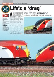
221101 ran more than 30,000kms on test in<br />
France before entering service with Virgin. On<br />
February 1 2002, the day it was named Louis<br />
Bleriot at Cahors, the unit shows off its tilt<br />
mechanism at Brive-la-Gaillarde in central<br />
France. INSET: Close up of tilt mechanism<br />
and bogie of 221101. BOTH: BEN JONES<br />
MASTERCLASS<br />
in France between August 2001 and March<br />
2002. Specific tilt tests were undertaken on the<br />
Paris-Limoges-Toulouse main line, on the<br />
notoriously tortuous section between Brive and<br />
Cahors in January/February 2002.<br />
For these tests, the cars were loaded with<br />
test equipment or weighted to simulate a full<br />
passenger load. To mark this feat of Anglo-French<br />
co-operation, 221101 was named<br />
Louis Bleriot at Cahors on February 1 2002.<br />
This was followed by high-speed trials at up<br />
to 137.5mph (125mph maximum plus 10%)<br />
between Le Mans and Nantes in western<br />
France, on lines cleared for 220km/h operation<br />
with TGVs. In total, the unit ran more than<br />
30,000km (18,640 miles) on French metals, a<br />
third of which was with tilt activated. After this,<br />
221101 was returned to Bombardier for a refit<br />
and eventually joined the fleet in the UK, being<br />
delivered out of sequence.<br />
External differences<br />
Internally, Class 220 and 221 are identical. The<br />
layout of bodyshells, saloons, toilet provision<br />
and shop car are standard across the fleet.<br />
Second Class saloons have a mix of dark blue<br />
and red seats largely in 2+2 ‘airline’ fashion with<br />
a few grouped around tables. ‘Club Class’ has 24<br />
seats with dark blue upholstery arranged in 2+1<br />
format with seats in both airline fashion and<br />
around tables of four or two.<br />
Between the saloon and driving cab of the<br />
DMF car is a small galley for serving hot food<br />
and drinks to First Class passengers.<br />
However, the major external difference is<br />
Meet the family<br />
After initial teething troubles, the Voyagers have become<br />
comparatively reliable and are said to be popular with<br />
passengers. Their rapid acceleration, 125mph top speed<br />
and reliability attracted the attention of Midland Mainline<br />
and later Hull Trains, which were both seeking to upgrade<br />
services from 100mph Class 170 Turbostars.<br />
MML took delivery of seven 9-car and 16 four-car<br />
Class 222 ‘Meridians’ in 2004/05, based on the non-tilting<br />
‘220’ but with a revised body design and improved interior.<br />
The units are used on London St Pancras-Leicester-Nottingham/Sheffield/Leeds<br />
services. During late-2006/early-2007<br />
some 9-car ‘222’ sets have been reduced to eight cars,<br />
losing one Motor Second car to strengthen other sets to<br />
five cars.<br />
In 2005, Hull Trains received four 4-car Class 222/1<br />
‘Pioneers’ to improve its King’s Cross-Hull services. These<br />
share a bodyshell design with MML’s trains and have<br />
a similar internal layout, albeit in HT corporate colours,<br />
rather than MML’s sober blue scheme. All four HT units are<br />
named after notable citizens of Hull.<br />
Bachmann announced in 2005 that it would produce<br />
a ‘OO’ gauge model of the MML Class 222, although this<br />
has since been quietly shelved. However, the company is to<br />
offer both MML and Hull Trains units in its Graham Farish<br />
‘N’ gauge range in 2007/08.<br />
Vehicle end detail on 220008 Draig Gymreig/<br />
Welsh Dragon at Nuneaton on August 18<br />
2002. MEL HOLLEY<br />
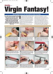
Firstly, test your Voyager on DC to<br />
1 check that everything is working well.<br />
Undo the four screws underneath the<br />
motor car - two at each end as shown<br />
circled. Insert strips of card between the<br />
body and chassis and gently remove the<br />
bodyshell.<br />
Place the body carefully away and<br />
2 undo the printed circuit board (PCB)<br />
screws on the chassis. Cut the wires from<br />
the PCB off as close as possible to the<br />
PCB. Group the pick-up wires together on<br />
each side of the chassis but do not confuse<br />
them with the wires to the motor! Cut<br />
off the plastic PCB mounting lugs which<br />
were underneath the PCB.<br />
Locate the decoder on top of the grey<br />
3 plastic motor cover and secure with<br />
a sticky pad. Cut the decoder wires to<br />
an appropriate length. The white, blue,<br />
purple, green and yellow wires will not<br />
be used in this car. I later moved the<br />
decoder to the right.<br />
24<br />
Subscribe at www.model-rail.com May Issue 2007
digital Voyager<br />
The modifications explained here are the<br />
same for the Class 220 and 221 variants<br />
produced by Bachmann in ‘OO’.<br />
I used the lighting supplied by the manufacturer,<br />
though Express Models also makes a<br />
lighting kit. Once I had completed the DCC<br />
easy - Skill Level - advanced<br />
installation I renumbered it as 220034<br />
Yorkshire Voyager and lightly weathered it<br />
using dry-brush techniques, particularly black<br />
deposits on the roof around the exhaust pipe.<br />
n A full article on detailing and weathering the<br />
Bachmann Class 221 will follow later this year.<br />
Shopping list<br />
✔ Three locomotive decoders with at<br />
least two function outputs - I used a Lenz<br />
LE1014E/Bachmann 36-550 available<br />
from Lenz/Bachmann dealers for about<br />
£13 each. I prefer to use locomotive<br />
decoders rather than accessory decoders<br />
such as the Lenz LF100XF for locomotive<br />
lighting as they will also work on DC,<br />
whereas the accessory decoder will not.<br />
This is useful for visiting friends’ layouts<br />
or using your model on a DC club layout.<br />
✔ Heatshrink tubing, available from<br />
electronics stockists such as Maplins<br />
✔ Sticky pad (supplied with Lenz<br />
decoders)<br />
✔ Insulating tape<br />
✔ Optional Fox Transfers for renumbering<br />
(F4763/20, £6.95) and Shawplan<br />
etched plates for renaming.<br />
Wire the decoder as follows, using heatshrink<br />
tubing to insulate the joint:<br />
4<br />
n Decoder black to two black pick-up wires<br />
n Decoder red to two red pick-up wires<br />
n Decoder grey to black motor wire<br />
n Decoder orange to red motor wire.<br />
Unplug the body to chassis power<br />
7 connection. Cut the red and black wires<br />
as close to the cab roof PCB as possible.<br />
Put these wires and plug on one side - they<br />
will be used shortly.<br />
Tools<br />
✔ small crosshead screwdriver<br />
✔ soldering iron and solder<br />
✔ wire strippers<br />
✔ pliers<br />
✔ Stanley knife<br />
VIRGIN VOYAGER<br />
I then secured the wires using insulating<br />
5 tape. Test the car on your programming<br />
track to ensure the installation was successful.<br />
Then replace the body and the four<br />
screws. Note the direction of travel of the<br />
car and mark the underframe accordingly.<br />
Ensure your cars are arranged in the correct<br />
order.<br />
Looking from underneath, the nearest<br />
8 bulb to you is the white main headlights,<br />
the next down is the red lights and at the<br />
very top of the cab is the white marker light.<br />
Group wires as follows, cutting decoder<br />
wires appropriately:<br />
A) one wire from each bulb together - this<br />
goes to the decoder blue wire<br />
B) the two other wires from the white bulbs<br />
together - this goes to the decoder yellow<br />
wire<br />
C) the remaining wire from the red bulb goes<br />
to the decoder white wire.<br />
I then secured the decoder to the car<br />
10 roof and tidied the wires with insulating<br />
tape. Be sure to route the wires well around<br />
the screw mounting - you don’t want to screw<br />
wires in half! I then replaced the body, the<br />
under cab section and the three screws and<br />
tested it. To program the decoders in the<br />
driving cars you’ll need to program them at<br />
the same time as the motor car or wire a light<br />
bulb across the tracks when programming.<br />
I programmed all three decoders to the same<br />
address.<br />
Now onto the driving cars. Taking the<br />
6 ‘Club Class’ coach first, undo three<br />
screws underneath, two at either end of the<br />
underframe fairing and one underneath the<br />
cab. Remove the separate plastic section<br />
which the cab screw was holding on. Use<br />
card strips in between the body and chassis<br />
again and remove the bodyshell.<br />
Again, use heatshrink tubing to insulate<br />
9 the joints and this is what it should look<br />
like. The orange, grey, green and purple<br />
wires are not used.<br />
For the other driving car, the instructions<br />
are as in steps 6 to 10, except that<br />
11<br />
in step 8, the two wires go to the decoder<br />
white wire and the single wire to the decoder<br />
yellow wire. And this is the result - head<br />
lights and tail lights which stay on even when<br />
the Voyager is static.<br />
May Issue 2007 Get the latest news at www.model-rail.com 25
Sound support<br />
JOHN FERGUSON tests Dapol’s claim<br />
that it is possible to install realistic<br />
digital sound in an ‘N’ gauge<br />
Virgin Voyager.<br />
When I saw the attractive box for this<br />
set at my dealer - John Dutfield in<br />
Chelmsford - I was impressed that<br />
Dapol had taken the initiative in<br />
providing the means to fit not only DCC lighting<br />
but a sound decoder as well. The<br />
set promised the most realistic model yet in ‘N’<br />
gauge with quality and detail finish to<br />
a very high standard.<br />
While the box has basic printed instructions<br />
for fitting the decoders, detail guidance needed<br />
for the sound decoder is only available on the<br />
Dapol website. There are two decoders used for<br />
lighting, one to each of the end cars, together<br />
with a sound decoder used also as the motor<br />
drive. If preferred, a normal motor drive<br />
decoder can be fitted in place of the sound<br />
decoder.<br />
I thought that having completed and tested<br />
the set-up a detail article would be useful for<br />
readers contemplating the purchase of this<br />
model. No advance skills are required.<br />
On its website Dapol shows an example of<br />
the process for fitting an ESU Loksound Micro<br />
sound decoder with motor drive and an<br />
associated loudspeaker. This type of sound<br />
decoder has the advantage that sounds can be<br />
installed and modified later.<br />
I purchased mine from South West Digital as<br />
it offered to install suitable sounds for the<br />
The triangle of lights with a single very bright<br />
headlight is a key feature of all modern trains<br />
- including the Class 220/221 Voyagers.<br />
VIRGIN TRAINS/MILEPOST 92 1 ⁄2<br />
model. It is supplied with a 6-pin plug to be<br />
inserted in the NEM socket provided for each<br />
decoder. Other sounds are available from the<br />
ESU website for downloading and installing,<br />
using the Loksound Programmer, but these are<br />
only suitable for European locomotives.<br />
For the two lighting decoders I used Lenz<br />
Silver Mini No. 10311s - the type that comes with<br />
a 6-pin plug. These are to control the lights but<br />
the built-in motor drive was not used. I found<br />
that they could not be programmed by my DCC<br />
command station to change the address in CV1<br />
or other CVs as with no motor connected the<br />
command station just reported errors.<br />
MASTERCLASS: DAPOL VOYAGER SOUND<br />
Here’s How You Can Do It…<br />
easy - Skill Level - advanced<br />
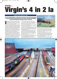
Cover of the box containing the ‘N’ gauge<br />
1Dapol Class 220.<br />
Driving car showing the lighting scheme<br />
2 with three white headlights leading.<br />
The plug from the sound decoder inserted<br />
3 in the NEM socket provided.<br />
May Issue 2007 Get the latest news at www.model-rail.com 27
MASTERCLASS: DAPOL VOYAGER SOUND<br />
This problem was easily overcome by<br />
mounting the car with the sound decoder -<br />
which also drives the motor - on the programming<br />
track together with one of the cars fitted<br />
with the Lenz decoder. The address for the<br />
model’s number in CV1 was then programmed<br />
to both decoders. The decoders then had the<br />
same address so that they acted together. The<br />
other car with the Lenz decoder was then<br />
exchanged with the first one and once again<br />
programmed with the sound decoder using the<br />
same address.<br />
If it was found (this did not happen in my<br />
case) that the lights are not alternately white at<br />
the front and red at the rear then using CV29<br />
adjustments for forward to reverse or vice<br />
versa should deal with the problem. I am<br />
indebted to a member of the Model Electronic<br />
Railway Group (MERG) for this advice.<br />
The model as supplied including the lighting<br />
units works satisfactorily on a DC system as<br />
special plugs have been fitted instead of DCC<br />
decoders.<br />
The installation of the Lenz decoders was very<br />
straightforward. The chassis to the two end cars<br />
was removed by springing the body way from<br />
the chassis. I used my finger nail rather than a<br />
metal tool as this seemed less likely to cause<br />
damage. To install the decoder it was simply a<br />
matter of removing the DC plugs and plugging<br />
in the Lenz decoders making absolutely sure<br />
that pin 1 on the decoder lined up with pin 1 on<br />
the socket. This is clearly marked. Careful<br />
inspection of the documentation for the decoder<br />
ensured that pin 1 was properly identified.<br />
Replacement of the chassis was again by<br />
springing the body outwards and pressing the<br />
chassis into position.<br />
The sound decoder was installed in the car<br />
with the motor again by removing the chassis,<br />
removing the DC plug, and plugging in the<br />
sound decoder. The position for the sound<br />
decoder is over one of the drive shafts mounted<br />
Here’s How You Can Do It…<br />
The sound decoder mounted on a<br />
4 Plastikard support above the drive shaft<br />
as recommended by Dapol.<br />
on a support made from Plastikard as shown in<br />
the photographs here and on the Dapol website.<br />
Wires for the loudspeaker must be taken<br />
through holes made in the ends of the cars<br />
leading to the other middle car next to the<br />
powered car. These need to be of very light<br />
gauge or they will affect the stability of the cars.<br />
White wire has been used to make this clear.<br />
The photographs show the loudspeaker<br />
mounted on the chassis, first having been<br />
trimmed with a sharp knife to reduce its width.<br />
Holes were drilled in the bottom of the chassis<br />
to let the sound out. No speaker enclosure is<br />
necessary or supplied.<br />
easy - Skill Level - advanced<br />
A side view of the Plastikard support<br />
5 for the sound decoder mounted over the<br />
drive shaft.<br />
Voyagers undergoing routine<br />
maintenance at the dedicated Central<br />
Rivers depot near Burton-on-Trent.<br />
The manual for the sound decoder is very<br />
comprehensive and allows for many adjustments<br />
including modifying the sound effects.<br />
One area of realism to get used to however is<br />
that on powering up the model with the sound<br />
switched on is there is a delay to simulate the<br />
motor coming to full power before the drive is<br />
connected. I have found the realism achieved<br />
enhances the pleasure that comes from the<br />
hobby.<br />
n John Ferguson is a member of the<br />
Model Electronic Railway Group. (MERG), web:<br />
www.merg.info MR<br />
Holes need to be drilled through the<br />
6 bottom of the body to let out the sound<br />
from the loudspeaker.<br />
Holes will be<br />
8 needed in<br />
both coaches<br />
for the speaker<br />
wires. In practice<br />
black wires<br />
should be used.<br />
Otherwise the<br />
installation<br />
process is<br />
relatively<br />
simple.<br />
The loudspeaker must be trimmed to<br />
7 reduce its width for mounting in the body.<br />
28<br />
Subscribe at www.model-rail.com May Issue 2007