Chilled Water Fan Coil Unit - Dalkia
Chilled Water Fan Coil Unit - Dalkia
Chilled Water Fan Coil Unit - Dalkia

You also want an ePaper? Increase the reach of your titles
YUMPU automatically turns print PDFs into web optimized ePapers that Google loves.
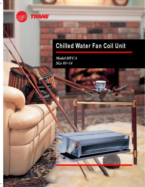
<strong>Chilled</strong> <strong>Water</strong> <strong>Fan</strong> <strong>Coil</strong> <strong>Unit</strong><br />
Model:HFCA<br />
Size 03~14
The Best Choice for Comfort<br />
=The Best Results<br />
Quiet Comfort<br />
• Slope coil avoid air flow perpendicular<br />
impact<br />
• Low noise permanent split capacitor<br />
motor<br />
• Metal fan wheel both statically and<br />
dynamically balanced<br />
• Treaded connection, match up duct<br />
collars and keyholes for hangers<br />
shorten installation time<br />
• Quick delivery helps meet tight<br />
installation schedules<br />
Latest Perfection<br />
• Cleaner, quieter and more efficient<br />
fin design.<br />
=The Best System<br />
Design for hidden comfort in home,<br />
office or shop. HFCA is easily<br />
installed in a false ceiling or closet,<br />
HFCA is the ideal solution for new or<br />
replacement applications.<br />
=Flexibility<br />
Easy to change water hand<br />
connections on the field.<br />
=The Best Fit<br />
Seven sizes to meet capacity<br />
requirements while minimizing the<br />
size fan coil needed<br />
One unit provides total comfort<br />
requirements: both cooling and<br />
heating<br />
Low height of just 250mm on all sizes<br />
means no difficulty in fitting tight<br />
ceiling applications<br />
=Reliability<br />
Trane’s history of innovation and<br />
technology leadership led to quality<br />
products making Trane a leader in the<br />
air conditioning markets worldwide.<br />
Trane’s commitment to customer’s<br />
needs for quality, efficiency and<br />
reliability is evident from the largest<br />
chiller to smallest fan coil.<br />
© American Standard Inc. 2006 2<br />
HFCA-PRC001-EN
HFCA Model Nomenclature<br />
H<br />
1<br />
F<br />
2<br />
C<br />
3<br />
DIGIT 1 - Position<br />
H = Horizontal<br />
DIGIT 2 - <strong>Unit</strong> Type<br />
F = <strong>Fan</strong> <strong>Coil</strong><br />
DIGIT 3 - Casing<br />
C = Concealed<br />
A<br />
4<br />
03<br />
5,6<br />
DIGIT 4 - Development Sequence<br />
A = First<br />
DIGIT 5.6 - Size / Nominal CFM<br />
03 = 300 CFM<br />
04 = 400 CFM<br />
06 = 600 CFM<br />
08 = 800 CFM<br />
10 = 1000 CFM<br />
12 = 1200 CFM<br />
14 = 1400 CFM<br />
C<br />
7<br />
N<br />
8<br />
DIGIT 7 - <strong>Coil</strong> Row, Connection Side<br />
A = 2 Row Cooling, Right Hand<br />
B = 2 Row Cooling, Left Hand<br />
C = 3 Row Cooling, Right Hand<br />
D = 3 Row Cooling, Left Hand<br />
E = 4 Row Cooling, Right Hand<br />
F = 4 Row Cooling, Left Hand<br />
G = 2 Row Cooling, 1 Row Heating, Right Hand<br />
H = 2 Row Cooling, 1 Row Heating, Left Hand<br />
J = 3 Row Cooling, 1 Row Heating, Right Hand<br />
K = 3 Row Cooling, 1 Row Heating, Left Hand<br />
S = Special<br />
DIGIT 8 - Electric Heat 115V / 220V (240V)<br />
N = None<br />
A = 1.0 kW(1.2 kW) Heater (Size 03~14)<br />
B = 1.5 kW(1.8 kW) Heater (Size 04~14)<br />
C = 2.0 kW(2.4 kW) Heater (Size 06~14)<br />
D = 2.5 kW(3.0 kW) Heater (Size 08~14)<br />
E = 3.0 kW(3.6 kW) Heater (Size 08~14)<br />
F = 3.5 kW(4.2 kW) Heater (Size 10~14)<br />
G = 4.0 kW(4.8 kW) Heater (Size 12~14)<br />
S = Special<br />
kW in bracket for 240V only<br />
H<br />
9<br />
DIGIT 9 - Motor Type<br />
N = Normal Duty Without Temperature Cutout-standard<br />
M = Normal Duty With Temperature Cutout<br />
H = High Static Without Temperature Cutout<br />
G = High Static With Temperature Cutout<br />
I = Normal Duty Without Temperature Cutout/With Ball Bearing<br />
J = Normal Duty With Temperature Cutout/With Ball Bearing<br />
E = High Static Without Temperature Cutout/With Ball Bearing<br />
F = High Static With Temperature Cutout/With Ball Bearing<br />
A = DCBL Motor For Low ESP(0~40pa)<br />
B = DCBL Motor For High ESP(40~100pa)<br />
S = Special<br />
1<br />
10<br />
N<br />
11<br />
A<br />
12<br />
N<br />
13<br />
B<br />
14<br />
DIGIT 10 - Voltage/Hertz/Phase<br />
1 = 220-240 / 50 / 1<br />
2 = 220-240 / 60 / 1<br />
5 = 115 / 60 / 1<br />
S = Special<br />
DIGIT 11 - Control Valve Package<br />
N = Thread Connection / Without Valve Package<br />
B = 2 Pipe System / With Single 2-Way 2 Position Valve / Without<br />
Thermostat<br />
C = 2 Pipe System / With Single 2-Way 2 Position Valve / With<br />
Cool Thermostat<br />
D = 2 Pipe System / With Single 2-Way 2 Position Valve / With<br />
Cool/Heat Thermostat<br />
E = 2 Pipe System / With Single 3-Way 2 Position Valve / Without<br />
Thermostat<br />
F = 2 Pipe System / With Single 3-Way 2 Position Valve / With Cool<br />
Thermostat<br />
G = 2 Pipe System / With Single 3-Way 2 Position Valve / With<br />
Cool/Heat Thermostat<br />
H = 4 Pipe System / With 2 Sets 2-Way 2 Position Valve / Without<br />
Thermostat<br />
I = 4 Pipe System / With 2 Sets 2-Way 2 Position Valve / With Cool/<br />
Heat Thermostat<br />
V = Standard Piping / Infrared Wireless Control (Cooling &<br />
Heating)<br />
W = 2 Pipe System / With Single 2-Way 2 Position Valve / Infrared<br />
Wireless Control (Cooling & Heating)<br />
X = 2 Pipe System / With Single 3-Way 2 Position Valve / Infrared<br />
Wireless Control (Cooling & Heating)<br />
1 = 2 Pipe System / With Single 2-Way 2 Position Valve / With<br />
Trane Wall Mounted Zone Sensor / ZN510 (Cooling Only)<br />
2 = 2 Pipe System / With Single 2-Way 2 Position Valve / With<br />
Trane Wall Mounted Zone Sensor / ZN510 (Cooling & Heating)<br />
3 = 2 Pipe System / With Single 2-Way Floating Valve / With Trane<br />
Wall Mounted Zone Sensor / ZN520 (Cooling Only)<br />
4 = 2 Pipe System / With Single 2-Way Floating Valve / With Trane<br />
Wall Mounted Zone Sensor / ZN520 (Cooling & Heating)<br />
5 = 2 Pipe System / With Single 3-Way 2 Position Valve / With<br />
Trane Wall Mounted Zone Sensor / ZN510 (Cooling Only)<br />
6 = 2 Pipe System / With Single 3-Way 2 Position Valve / With<br />
Trane Wall Mounted Zone Sensor / ZN510 (Cooling & Heating)<br />
7 = 2 Pipe System / With Single 3-Way Floating Valve / With Trane<br />
Wall Mounted Zone Sensor / ZN520 (Cooling Only)<br />
8 = 2 Pipe System / With Single 3-Way Floating Valve / With Trane<br />
Wall Mounted Zone Sensor / ZN520 (Cooling & Heating)<br />
DIGIT 12 - Drain Pan<br />
A = STD. Galvanized Steel / 5mm PE Insulation<br />
B = Long Galvanized Steel / 5mm PE Insulation<br />
C = STD. SUS/5mm PE Insulation<br />
D = Long SUS/5mm PE Insulation<br />
E = STD. Galvanized Steel / 6mm Non-Flammable BS476, Part7<br />
Insulation<br />
F = Long Galvanized Steel / 6mm Non-Flammable BS476, Part7<br />
Insulation<br />
3<br />
G = STD. SUS / 6mm Non-Flammable BS476, Part7 Insulation<br />
H = Long SUS / 6mm Non-Flammable BS476, Part7 Insulation<br />
I = STD. Galvanized Steel / 10mm PE Insulation<br />
J = Long Galvanized Steel / 10mm PE Insulation<br />
K = STD. SUS / 10mm PE Insulation<br />
L = Long SUS / 10mm PE Insulation<br />
M = STD. Galvanized Steel / 15mm PE Insulation<br />
O = Long Galvanized Steel / 15mm PE Insulation<br />
P = STD. Galvanized Steel / 9mm Non-Flammable BS476, Part7<br />
Insulation<br />
Q = Long Galvanized Steel / 9mm Non-Flammable BS476, Part7<br />
Insulation<br />
R = STD. SUS / 15mm PE Insulation<br />
T = Long SUS / 15mm PE Insulation<br />
U = STD. Galvanized Steel / 15mm Non-Flammable BS476, Part7<br />
Insulation<br />
V = Long Galvanized Steel / 15mm Non-Flammable BS476, Part7<br />
Insulation<br />
W = STD. Galvanized Steel / 25mm Non-Flammable BS476, Part7<br />
Insulation<br />
X = Long Galvanized Steel / 25mm Non-Flammable BS476, Part7<br />
Insulation<br />
Y = STD. SUS / 25mm Non-Flammable BS476, Part7 Insulation<br />
Z = Long SUS / 25mm Non-Flammable BS476, Part7 Insulation<br />
S = Special<br />
DIGIT 13 - Plenum / Filters<br />
N = Without Return Plenum / No Filter<br />
A = With Return Plenum / 4mm P.P Nylon Filter<br />
B = With Return Plenum / 12mm Aluminum Media<br />
C = With Return Plenum / 12mm Foam Media<br />
D = With Return Plenum / 20mm Aluminum Media<br />
E = With Return Plenum / 20mm Foam Media<br />
F = With Return Plenum / No Filter<br />
G = With Return Plenum / 25mm Aluminum Media<br />
I = With Return Plenum / 20mm P.P. Nylon Filter<br />
K = With Return Plenum / 12mm Non-Woven<br />
L = With Return Plenum / 20mm Non-Woven<br />
P = With Return Plenum / 25mm Foam Media<br />
S = Special<br />
DIGIT 14 - Design Sequence<br />
B = Second<br />
Note:<br />
1. HFCA will not support sweat connection for standard piping.<br />
2. The wiring of thermostat or zone sensor to motors, ZN or valves<br />
must be done on job site.<br />
3. Non-flammable PU insulation meet the regulation of BS476<br />
part7 class 1 and part6 class O.<br />
HFCA-PRC001-EN
Performance Data<br />
Cooling Capacity (Example)<br />
Cooling Capacity : kW<br />
EAT : 26.0˚C / 60.0%<br />
ESP : 30 / 60 Pa (Normal / Hi-Static) Applicable<br />
Model<br />
03<br />
04<br />
06<br />
08<br />
10<br />
12<br />
14<br />
Nominal<br />
Airflow<br />
(CMH)<br />
509<br />
678<br />
1018<br />
1357<br />
1696<br />
2036<br />
2366<br />
WTR<br />
(˚C)<br />
3.0<br />
5.0<br />
7.0<br />
3.0<br />
5.0<br />
7.0<br />
3.0<br />
5.0<br />
7.0<br />
3.0<br />
5.0<br />
7.0<br />
3.0<br />
5.0<br />
7.0<br />
3.0<br />
5.0<br />
7.0<br />
3.0<br />
5.0<br />
7.0<br />
SH<br />
3.19<br />
2.92<br />
2.62<br />
4.81<br />
4.45<br />
4.08<br />
5.32<br />
4.86<br />
4.39<br />
6.92<br />
6.38<br />
5.81<br />
8.42<br />
7.60<br />
6.66<br />
10.34<br />
9.41<br />
8.43<br />
11.19<br />
10.30<br />
9.35<br />
TH<br />
5.17<br />
4.55<br />
3.85<br />
7.81<br />
7.02<br />
6.13<br />
8.58<br />
7.55<br />
6.41<br />
11.15<br />
9.90<br />
8.55<br />
13.48<br />
11.60<br />
9.27<br />
16.56<br />
14.41<br />
12.03<br />
17.92<br />
16.10<br />
14.08<br />
Entering <strong>Water</strong> Temperature<br />
5˚C 7˚C 9˚C<br />
WFR<br />
0.41<br />
0.22<br />
0.13<br />
0.62<br />
0.33<br />
0.21<br />
0.68<br />
0.36<br />
0.22<br />
0.89<br />
0.47<br />
0.29<br />
1.07<br />
0.55<br />
0.32<br />
1.32<br />
0.69<br />
0.41<br />
1.43<br />
0.77<br />
0.48<br />
Cooling Rows : 3<br />
Motor Frequency : 50Hz<br />
TH : Total Cooling Capacity, kW<br />
WPD<br />
7.60<br />
2.47<br />
1.02<br />
21.93<br />
7.35<br />
3.20<br />
9.38<br />
3.04<br />
1.26<br />
17.68<br />
5.80<br />
2.48<br />
4.87<br />
1.52<br />
0.57<br />
8.05<br />
2.56<br />
1.03<br />
14.15<br />
4.23<br />
2.15<br />
SH<br />
2.86<br />
2.59<br />
2.32<br />
4.32<br />
3.97<br />
3.63<br />
4.78<br />
4.33<br />
3.90<br />
6.23<br />
5.69<br />
5.19<br />
7.56<br />
6.77<br />
5.85<br />
9.30<br />
8.40<br />
7.48<br />
10.06<br />
9.17<br />
8.21<br />
© American Standard Inc. 2006 4<br />
HFCA-PRC001-EN<br />
TH<br />
4.43<br />
3.78<br />
3.10<br />
6.72<br />
5.87<br />
5.02<br />
7.35<br />
6.27<br />
5.16<br />
9.56<br />
8.24<br />
6.97<br />
11.50<br />
9.54<br />
7.15<br />
14.14<br />
11.93<br />
9.56<br />
15.06<br />
13.67<br />
11.49<br />
WFR<br />
0.35<br />
0.18<br />
0.11<br />
0.53<br />
0.28<br />
0.17<br />
0.58<br />
0.30<br />
0.18<br />
0.76<br />
0.39<br />
0.24<br />
0.91<br />
0.46<br />
0.24<br />
1.12<br />
0.57<br />
0.33<br />
1.24<br />
0.65<br />
0.39<br />
SH : Sensible Cooling Capacity, kW<br />
WPD : <strong>Water</strong> Pressure Drop, M<br />
WFR : <strong>Water</strong> Flow Rate, L / S<br />
WPD<br />
5.74<br />
1.77<br />
0.69<br />
16.63<br />
5.31<br />
2.23<br />
7.06<br />
2.17<br />
0.86<br />
13.33<br />
4.16<br />
1.72<br />
3.64<br />
1.07<br />
0.36<br />
6.03<br />
1.82<br />
0.68<br />
11.51<br />
3.32<br />
1.40<br />
SH<br />
2.54<br />
2.30<br />
2.06<br />
3.84<br />
3.52<br />
3.22<br />
4.24<br />
3.85<br />
3.46<br />
5.55<br />
5.06<br />
4.62<br />
6.71<br />
5.98<br />
5.12<br />
8.26<br />
7.46<br />
6.62<br />
8.93<br />
8.04<br />
7.13<br />
TH<br />
3.65<br />
3.02<br />
2.39<br />
5.57<br />
4.74<br />
3.97<br />
6.05<br />
5.03<br />
3.99<br />
7.88<br />
6.63<br />
5.48<br />
9.40<br />
7.53<br />
5.15<br />
11.60<br />
9.53<br />
7.25<br />
13.15<br />
11.09<br />
8.89<br />
Spec./ Input Power<br />
Model<br />
03 04 06 08 10 12<br />
Nominal Airflow (CMH)<br />
Input Power (Watts)*<br />
509 678 1018 1357 1696 2036<br />
Hi-Static Motor<br />
97 110 162 200 286 324<br />
Normal Motor<br />
*Available with 115V/60Hz, 220V/50Hz, or 220V/60Hz<br />
Options:<br />
Heat Capacity Type (kW)<br />
88 98 138 180 218 250<br />
== Hot <strong>Water</strong> 1Row<br />
2.86 3.71 4.95 6.16 6.91 7.94<br />
EWT=55˚C; EAT=21˚C; WFR=0.3L/S<br />
== Electric Sheathed Element<br />
1.0 1.5 2<br />
3 3.5 4<br />
Plenum/Filters<br />
Available with high temperature cutout<br />
Return air plenum with filters-washable foam, PP nylon or aluminium<br />
Note: It reserves the right to change design and specification without notice.<br />
WFR<br />
0.29<br />
0.14<br />
0.08<br />
0.44<br />
0.23<br />
0.14<br />
0.48<br />
0.24<br />
0.14<br />
0.63<br />
0.32<br />
0.19<br />
0.75<br />
0.36<br />
0.18<br />
0.92<br />
0.45<br />
0.25<br />
1.05<br />
0.53<br />
0.30<br />
WPD<br />
4.03<br />
1.18<br />
0.44<br />
11.80<br />
3.60<br />
1.45<br />
4.96<br />
1.46<br />
0.54<br />
9.39<br />
2.81<br />
1.12<br />
2.53<br />
0.70<br />
0.20<br />
4.22<br />
1.21<br />
0.42<br />
8.21<br />
2.24<br />
0.91<br />
14<br />
2366<br />
400<br />
317<br />
9.26<br />
4
Dimension Data and Weight<br />
Model HFCA<br />
Model HFCA with Return Plenum and Filter<br />
Note :<br />
1. Dimensions in mm.<br />
2. C1 is the dimension of long drain pan.<br />
3. Right hand coil connection shown.<br />
4. Wiring connection same side as coil and drain connections.<br />
5. Access door below unit required to service fan motor.<br />
6. Wiring controls and junction box not supplied by Trane.<br />
7. Terminal strip supplied with electric heat option only.<br />
Model Size<br />
HFCA-03<br />
HFCA-04<br />
HFCA-06<br />
HFCA-08<br />
HFCA-10<br />
HFCA-12<br />
HFCA-14<br />
A<br />
480<br />
730<br />
865<br />
1150<br />
1320<br />
1570<br />
1650<br />
External Dimensions(mm) Number of Net Weight(Kg)<br />
B<br />
530<br />
780<br />
915<br />
1200<br />
1370<br />
1620<br />
1700<br />
C<br />
665<br />
915<br />
1050<br />
1335<br />
1505<br />
1755<br />
1835<br />
C1<br />
964<br />
1164<br />
1349<br />
1624<br />
1824<br />
2074<br />
2154<br />
D<br />
490<br />
740<br />
875<br />
1160<br />
1330<br />
1580<br />
1660<br />
<strong>Fan</strong>(s)<br />
1<br />
2<br />
2<br />
2<br />
3<br />
4<br />
4<br />
Motor(s)<br />
1<br />
1<br />
1<br />
1<br />
2<br />
2<br />
2<br />
2Row<br />
19<br />
23<br />
25<br />
30<br />
40<br />
44<br />
47<br />
3Row<br />
20<br />
25<br />
27<br />
33<br />
43<br />
48<br />
51<br />
5<br />
4Row<br />
21<br />
26<br />
29<br />
35<br />
46<br />
52<br />
55<br />
Net Weight-With Return<br />
plenum and Filter (Kg)<br />
2Row 3Row 4Row<br />
22 23 24<br />
27 29 30<br />
31 33 35<br />
38 41 43<br />
48 51 54<br />
55 58 63<br />
59 62 67<br />
Operating Weight(Kg)<br />
2Row<br />
19.7<br />
24.7<br />
26.2<br />
31.6<br />
41.8<br />
46.2<br />
49.3<br />
3Row<br />
21<br />
26<br />
28.8<br />
35.4<br />
45.7<br />
51.2<br />
54.4<br />
4Row<br />
22.3<br />
28.3<br />
31.4<br />
38.1<br />
49.6<br />
56.3<br />
59.5<br />
Operating Weight-With Return<br />
plenum and Filter (Kg)<br />
2Row<br />
22.7<br />
28.7<br />
32.2<br />
39.6<br />
50.8<br />
57.2<br />
61.3<br />
3Row<br />
24<br />
30<br />
34.8<br />
43.4<br />
54.7<br />
61.2<br />
65.4<br />
4Row<br />
26.3<br />
32.3<br />
37.4<br />
46.1<br />
58.6<br />
67.3<br />
71.5<br />
HFCA-PRC001-EN
Sound Power Level<br />
Notes:<br />
1. Data referenced to 10-12 Motor Type<br />
Normal<br />
Hi-Static<br />
<strong>Unit</strong><br />
Octave Band (dB) & Center Frequency (Hz) Octave Band (dB) & Center Frequency (Hz)<br />
Speed<br />
Model 63 125 250 500 1000 2000 4000 8000 63 125 250 500 1000 2000 4000 8000<br />
High 38 51 48 47 44 43 39 34 43 57 54 54 49 50 39 40<br />
03 Medium 33 46 43 42 39 38 34 29 37 51 48 48 43 45 34 34<br />
Low 29 42 39 38 35 34 30 25 32 46 43 43 38 40 30 29<br />
High 40 53 48 50 45 44 37 38 46 61 57 56 52 51 44 43<br />
04 Medium 45 48 43 45 40 39 32 31 40 55 51 50 46 45 38 37<br />
Low 41 44 39 41 36 35 38 27 35 50 46 45 41 40 33 32<br />
High 44 57 52 53 48 47 40 39 48 61 59 58 54 53 44 42<br />
06 Medium 39 52 47 48 43 42 35 34 42 55 53 52 48 47 38 36<br />
Low 35 48 43 44 39 38 31 30 38 51 49 48 44 43 34 32<br />
High 46 58 52 53 51 50 42 41 48 62 59 60 57 55 46 45<br />
08 Medium 41 53 47 48 46 45 37 36 42 56 53 54 51 49 40 39<br />
Low 37 49 43 44 42 41 33 32 38 52 49 50 47 45 36 35<br />
High 47 60 56 55 53 51 44 44 51 64 61 60 59 55 47 46<br />
10 Medium 42 55 51 50 48 46 39 39 45 58 55 54 53 49 41 40<br />
Low 38 51 47 46 44 42 35 35 40 53 50 49 48 44 36 35<br />
High 48 62 57 56 52 51 44 46 52 65 61 61 57 58 46 47<br />
12 Medium 43 57 52 51 47 46 39 41 46 59 55 55 51 52 40 41<br />
Low 39 53 48 47 43 42 35 37 41 54 50 50 46 47 35 36<br />
High 50 63 60 57 54 52 48 45 54 65 62 63 60 57 50 48<br />
14 Medium 45 58 55 52 49 47 43 40 48 59 56 57 54 51 44 42<br />
Low 41 54 51 48 45 43 39 35 43 54 52 52 49 46 39 37<br />
watts.<br />
2. Above performance determined with both Normal static motor and Hi-static motor operating against 0<br />
Pa ESP (no ducting, ceiling material or other sound attenuating materials used).<br />
Wiring Diagram<br />
Connection / Piping<br />
Model HFCA <strong>Coil</strong> Connections<br />
Cooling & Heating <strong>Coil</strong> Connection Dimensions<br />
2 Row Cooling<br />
3 Row ( )<br />
1 Row Heating<br />
<strong>Unit</strong><br />
Size<br />
03~14<br />
A B C D E F G H<br />
Left /<br />
Hand<br />
Right<br />
69.6 104.2 138.8 173.6 59.8 171.3 134.2 97<br />
3 Row Cooling<br />
4 Row ( )<br />
1 Row Heating<br />
<strong>Unit</strong><br />
Size<br />
03~14<br />
A B C D E F G H<br />
Left /<br />
Hand<br />
Right<br />
68.1 58.4 115.9 183.1 58.6 158.6 158.6 108.6<br />
<strong>Unit</strong> 2 Row <strong>Coil</strong> 3 Row <strong>Coil</strong> 4 Row <strong>Coil</strong><br />
Size<br />
03~14<br />
A C E F A C E F A C E F<br />
Left /<br />
Hand<br />
Right<br />
57 178 51 181 57 178 51 181 41 174 60 176<br />
Note:<br />
1.Dimension in mm<br />
2. 25.4 mm=1 in.<br />
Cooling Connection Dimensions<br />
© American Standard Inc. 2006 6<br />
HFCA-PRC001-EN
Product Specification Options<br />
=General<br />
• Fabricated with a rigid galvanized steel<br />
casing.<br />
• The DIDW centrifugal fans have<br />
balanced, galvanized steel, and<br />
forward curved blades.<br />
• The fan board and the top of coil casing<br />
have insulation of 6mm thickness,<br />
108 kg/m3 high-density non-flammable<br />
PU foam.<br />
• Interchangable coil direction to match<br />
water connections on the field.<br />
• An optional return air plenum is<br />
available to allow the connection<br />
different types of filter.<br />
• IEC 60335 safety certified.<br />
=Motor<br />
• Motor is of permanent split capacitor<br />
type for maximum efficiency and low<br />
noise with sealed sleeve bearing and<br />
permanent lubrication.<br />
• The motor capacitor is totally enclosed<br />
in a metal shield, and attached to the<br />
motor. The motor lead-out wires are<br />
enclosed by flexible metal conduit and<br />
providing protection against damage.<br />
• Optional ball bearing.<br />
• CE and CAS safety certified.<br />
=<strong>Coil</strong><br />
• The coil can have 2,3 or 4 rows, with<br />
copper tubes mechanically bonded<br />
into slit aluminum fin collars.<br />
• <strong>Water</strong> inlet / outlet connections are<br />
3/4-inch female pipe thread (JIS B<br />
0203-1966). Header assembly is a<br />
one-piece casting, which enables to<br />
connect steel pipe directly.<br />
• <strong>Coil</strong> assembly is tested over 20 kg/<br />
cm2 .<br />
• A manual air vent is fitted with a drain<br />
line to the drain pan to avoid any water<br />
drips when venting.<br />
• A water drain is located at the bottom<br />
of the coil header.<br />
=Drain Pan<br />
The drain pan is 25mm depth with 0.8mm<br />
thickness galvanized steel c/w internal<br />
epoxy resin coating.<br />
For sure without leakage occur, the<br />
fabrication of drain pan by one-piece<br />
stamping process with seamless and no<br />
joint. The standard insulation material is<br />
5mm thickness, 27 kg/m3 density PE<br />
foam. The drain pan has one 3/4-inch<br />
male pipe thread (JIS B 0203-1966)<br />
connection.<br />
7<br />
=Heater<br />
Two types of heating device are<br />
available: hot water and electric<br />
sheathed heating element. Please<br />
check technical data for such different<br />
types of heating capacity.<br />
Meet Australia safety code AS 1668.1<br />
(Section 2.9), and AS 3102.<br />
=Plenum & Filters<br />
=S430(Standard) / S304(Option)<br />
Stainless Steel Drain Pan<br />
=Blue Fin<br />
The blue fin with vinyl-epoxy-based<br />
coating that has been tested under<br />
ASTM B117, and thus of higher<br />
corrosion resistance than aluminum fin<br />
stock.<br />
=Factory-mounted Control Valve<br />
Package<br />
Factory mounted and tested for options<br />
of 2way or 3way control valve package,<br />
and provision with or without thermostat.<br />
=Trane Building Management<br />
System<br />
The Tracer Summit system is<br />
designed for monitoring and control air<br />
conditioning system, lighting and other<br />
controllable devices for building.<br />
Such Building Control <strong>Unit</strong> (BCU)<br />
manages all <strong>Unit</strong> Control Moduls (UCM)<br />
for different zones management. Each<br />
UCM performs scan on couples of<br />
HFCA equips ZN controller in specific<br />
zone and regularly report to the central<br />
system.<br />
HFCA-PRC001-EN
The Trane <strong>Fan</strong> <strong>Coil</strong>...<br />
...Invented by Trane<br />
...Perfected by Trane<br />
Trane<br />
A business of<br />
American Standard Companies<br />
http : // www.trane.com<br />
An American-Standard Company<br />
Since 1885, Trane has been at the<br />
technological forefront of air conditioning.<br />
The company's pioneering spirit,<br />
commitment to research and pursuit of<br />
quality have made it a world leader in the<br />
manufacture of water chillers.<br />
FM 38631<br />
ISO 9001 Qualified factory - Trane Taiwan<br />
Literature Order Number<br />
File Number<br />
Supersedes<br />
Stocking location<br />
Over 70 years ago Trane produced the first<br />
fan coil unit and in so doing created a<br />
product which is now built worldwide. The<br />
universal acceptance of this product has<br />
prompted Trane to focus the same<br />
engineering experience to the fan coil as<br />
given to the refrigeration products.<br />
HFCA-PRC001-EN-0106<br />
HFCA-TS-14<br />
HFCA-PRC001-EN-1204<br />
Taipei, Taiwan<br />
Since The Trane Company has a policy of continuous product improvement, it reserves the right to change design and<br />
specifications without notice.