to Download - The Minster Machine Company
to Download - The Minster Machine Company
to Download - The Minster Machine Company

Create successful ePaper yourself
Turn your PDF publications into a flip-book with our unique Google optimized e-Paper software.
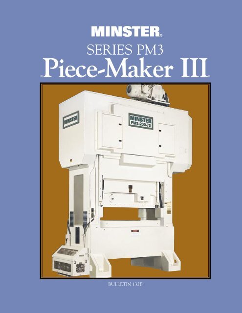
MINSTER®<br />
SERIES PM3<br />
®Piece-Maker III®<br />
BULLETIN 132B
MINSTER®<br />
Series PM3<br />
Piece-Maker III®<br />
Two Point, Eccentric Shaft<br />
Dynamically Balanced,<br />
Progressive Die,<br />
Straight Side Presses<br />
<strong>Minster</strong> Series PM3 presses provide<br />
the ultimate in consistent accuracy<br />
in au<strong>to</strong>mated high speed blanking<br />
operations in the 125 <strong>to</strong> 300 <strong>to</strong>n<br />
range.<br />
<strong>The</strong> PM3 was designed specifically for<br />
lamination work. <strong>The</strong>refore, many<br />
of the PM3’s features help insure<br />
that the machine will maintain its<br />
fine accuracies throughout years of<br />
operation.<br />
Expensive lamination dies last longer<br />
in a <strong>Minster</strong> PM3 because of its<br />
unique design. <strong>The</strong> massive frame,<br />
full eccentric shaft with six main<br />
bearings, along with the heavy steel<br />
connections and wrist pins combine<br />
<strong>to</strong> provide a machine that is more<br />
stable at high lamination speeds.<br />
PM3 presses also feature hydrostatic<br />
and hydrodynamic slide guiding and<br />
main bearing support that accurately<br />
guide the punch in<strong>to</strong> the die <strong>to</strong><br />
increase die life. In addition, an<br />
exclusive “hydraulic supported screw<br />
thread” system removes the clearances<br />
from slide shutheight adjustment<br />
parts, enhancing bot<strong>to</strong>m-dead-center<br />
repeatability and part consistency.<br />
In-Die Staking<br />
Unique features such as shutheight<br />
stabilization, hydraulic supported<br />
screw threads, a deep slide with long<br />
gib guiding, hydraulic quick lift slide<br />
and consistent slide bot<strong>to</strong>m-deadcenter<br />
repeatability make the PM3<br />
the ideal press for in-die staking<br />
operations. Add <strong>to</strong> these features the<br />
adjustable-in-motion (A.I.M.) control<br />
and they provide accuracy so critical<br />
when staking laminations within the<br />
die, while at the same time promote<br />
increased die life and die accessibility.<br />
2
9<br />
8<br />
3<br />
12<br />
11<br />
1<br />
3<br />
2<br />
5<br />
10<br />
7<br />
4<br />
6
Normal Crankshaft<br />
Eccentric Shaft<br />
L+2T<br />
L<br />
L=Distance Between Bearings<br />
T=Thickness of Cheek<br />
4<br />
Cast Construction<br />
Reduces Vibration. 1<br />
<strong>Minster</strong> Piece-Maker PM3 Series<br />
dynamically-balanced presses feature<br />
four-piece tie rod cast construction in<br />
the 125 and 200-<strong>to</strong>n models, while the<br />
PM3-300 has a welded crown and bed.<br />
<strong>Minster</strong>’s construction provides the<br />
compressive strength and vibration dampening<br />
so essential in building a precision<br />
press for progressive die work. <strong>The</strong> PM3<br />
gives the user less punch wear, better die<br />
life and greater part accuracy because the<br />
vibration is held <strong>to</strong> a minimum.<br />
Crown and Eccentric 2<br />
Shaft Provide Strength<br />
and Resist Deflection.<br />
<strong>The</strong> massive crown of the <strong>Minster</strong> PM3<br />
is engineered <strong>to</strong> withstand the severe<br />
stresses of lamination operation. A deep<br />
crown design backs up the eccentric shaft<br />
at any angle against forces created by the<br />
application, and load carrying members<br />
evenly distribute these forces in<strong>to</strong> the<br />
crown structure.<br />
In addition, the eccentric shaft provides<br />
these benefits:<br />
• Resists deflection.<br />
• Bearings are closer <strong>to</strong> the connection<br />
where the stamping force is exerted.<br />
• Allows for connections <strong>to</strong> be moved<br />
farther apart.<br />
• Resists tipping forces associated<br />
with progressive die work.<br />
• It is a full <strong>to</strong>rsional member.<br />
Precision-Fitted Support Block.<br />
A precision-fitted support block between<br />
the main bearing caps and the <strong>to</strong>p of the<br />
uprights helps relieve the stresses placed<br />
on bearing cap screws by snap-thru<br />
forces and adds <strong>to</strong> the rigidity of the<br />
eccentric shaft.<br />
Rigid Slide and<br />
Connections.<br />
<strong>The</strong> PM3 slide is designed <strong>to</strong> minimize<br />
deflection under full loading. <strong>The</strong> heavy<br />
steel connections combined with the large<br />
wrist pins are made specifically for high<br />
speed blanking. This feature, designed <strong>to</strong><br />
handle snap-through forces equal <strong>to</strong> 50%<br />
<strong>to</strong>nnage rating of the press, reduces punch<br />
penetration and promotes die life.<br />
4<br />
3
Massive Bed for Stability<br />
and Precision. 5<br />
<strong>The</strong> massive bed of the PM3<br />
minimizes deflection, increasing die<br />
life and improving part quality. In<br />
addition, the bed design incorporates<br />
troughs <strong>to</strong> collect die lubrication.<br />
Large bed openings provide access for<br />
lamination stacking chutes.<br />
Eight Point Hydrostatic/<br />
Hydrodynamic Gibbing<br />
for Precision Slide<br />
Guiding.<br />
<strong>The</strong> PM3 slide is guided by square<br />
gibbing at each corner, incorporating<br />
both hydrostatic and hydrodynamic<br />
bearing technology. <strong>The</strong> hydrostatic<br />
and hydrodynamic guiding design<br />
work in tandem <strong>to</strong> provide constant<br />
centering force throughout the press<br />
stroke, resisting the slide tipping<br />
movements caused by the high impact<br />
loading of lamination stamping. This<br />
guiding design promotes better part<br />
consistency and longer die life and,<br />
with the slide being centered in a<br />
static mode, allows for more accurate<br />
MINSTER® Moni<strong>to</strong>rFlow<br />
Continuous, Moni<strong>to</strong>red<br />
Press Lubrication.<br />
<strong>The</strong> patented <strong>Minster</strong> Moni<strong>to</strong>rFlow<br />
Pressurized<br />
Recirculating<br />
Oil Lubrication<br />
System supplies<br />
a continuous<br />
flow of filtered<br />
oil under<br />
pressure <strong>to</strong> all<br />
bearing surfaces.<br />
It also moni<strong>to</strong>rs<br />
the flow <strong>to</strong><br />
these points as well as oil level and<br />
pressure in the entire system, and<br />
protects the bearings by s<strong>to</strong>pping<br />
the press operation in the event of a<br />
lubrication fault. <strong>The</strong> PMC Control<br />
Screen instantly shows which flow<br />
switch signalled the fault, helping <strong>to</strong><br />
pinpoint the problem area.<br />
7<br />
6<br />
5<br />
Spacer<br />
Slide<br />
<strong>The</strong> Basics of<br />
Hydrostatic/Hydrodynamic Technology<br />
Hydrostatic pressure applied from all gib surfaces keeps slide<br />
centered when in a static condition and when slide is moving at<br />
a slow velocity such as near BDC. Hydrodynamic pressure also<br />
aids in centering the slide through the high velocity portion of<br />
its stroke. <strong>The</strong> result is extreme guiding accuracy and resistance<br />
<strong>to</strong> tipping moment at all points of the slide stroke.<br />
SLIDE REMAINS CENTERED F-B & R-L WITH<br />
HYDROSTATIC/HYDRODYNAMIC GUIDING<br />
SLIDE<br />
SLIDE MAY MOVE OFF- CENTER F-B & R-L WITHOUT<br />
HYDROSTATIC/HYDRODYNAMIC GUIDING<br />
SLIDE<br />
Slide<br />
Wear Plate<br />
Press<br />
Upright<br />
GIB<br />
GIB<br />
Laminated<br />
Spacer<br />
Gib<br />
Gib Wear Plate
Flywheel Drive Arrangement for<br />
Maximum Press Efficiency. 8<br />
<strong>The</strong> <strong>Minster</strong> PM3 Series presses are flywheel type presses<br />
running at higher speeds for punching, notching, and<br />
blanking operations on lamination materials. <strong>The</strong> clutch<br />
and brake unit is mounted on the eccentric shaft and the<br />
flywheel rotates on anti-friction bearings. An eddy-current<br />
brake supplies quick slowdown of flywheel for responsive<br />
operating speed changes.<br />
High Performance, Hydraulic Clutch and<br />
Brake Unit. 9<br />
<strong>The</strong> <strong>Minster</strong> PM3 delivers the maximum <strong>to</strong>rque possible <strong>to</strong><br />
provide fast starting and s<strong>to</strong>pping through a hydraulicallyactuated<br />
friction clutch and synchronized, spring-applied disc<br />
brake. <strong>The</strong> hydraulic pressure applied <strong>to</strong> engage the clutch<br />
also disengages the brake.<br />
Dynamic Balancer System.<br />
<strong>The</strong> Dynamic Balancing System on the PM3 greatly reduces<br />
the effect of the slide inertia forces caused by running at<br />
high speeds. This reciprocating balancer helps maintain<br />
precise slide bot<strong>to</strong>m-dead-center repeatability resulting in<br />
less die wear and greater part accuracy. It also allows the<br />
press <strong>to</strong> run at higher speeds and reduces press vibration.<br />
10<br />
Precise Shutheight Adjustment.<br />
Shutheight changes on the PM3 are made<br />
through two large connection screws. An<br />
electro-hydraulically operated shutheight<br />
adjustment mechanism is standard.<br />
11<br />
6<br />
Shutheight Indica<strong>to</strong>r. A digital shutheight<br />
indica<strong>to</strong>r gives the opera<strong>to</strong>r a constant read-out of<br />
the dimensional opening between the slide face<br />
and the bed or bolster, displaying <strong>to</strong> a thousandth<br />
of an inch. (Metric calibration is also available.)<br />
Hydraulically-Supported Screw Threads 12<br />
PM3 presses incorporate hydraulically-supported screw threads, utilized as part of the Adjustable-<br />
In-Motion option. This feature eliminates the effects of vertical clearances by introducing an<br />
oil film between the threads, while still allowing rotation of the adjusting nut during stamping<br />
operation. <strong>The</strong> extreme stiffness of the system reduces snap-thru effects, resulting in reduced punch<br />
penetration contributing <strong>to</strong> increased die life.<br />
PM3 Adjustment Screw Adjustment Screw<br />
With Hydraulically- Without Hydraulic<br />
Supported Threads Support<br />
Clearance Removed<br />
By Hydraulic Support.<br />
Pressurized<br />
Oil In Threads No Hydraulic Support<br />
With Resulting<br />
Clearances.
Hydraulic<br />
Quick-Lift.<br />
Quick access <strong>to</strong> dies is<br />
provided by a hydraulic<br />
system which lifts the<br />
slide as much as three<br />
inches (76 mm). <strong>The</strong><br />
hydraulic system returns<br />
the slide <strong>to</strong> the original<br />
shutheight position<br />
against a mechanical s<strong>to</strong>p,<br />
maintaining <strong>to</strong>ol settings.<br />
This feature enhances die<br />
accessi-bility and allows<br />
fast and easy unsticking<br />
from the bot<strong>to</strong>m even<br />
with shorter strokes and<br />
higher production speeds<br />
associated with lamination<br />
stamping, thus<br />
contributing <strong>to</strong> greater<br />
production efficiency.<br />
Mechanical<br />
S<strong>to</strong>p<br />
SLIDE<br />
Other Options.<br />
• Adjustment-In-Motion (A.I.M.) • Feeds<br />
• Die Space Enclosures • S<strong>to</strong>ck Lubrication<br />
• Oil Cooler • Material Handling Systems<br />
• Quick-Die-Change Systems & Rollers • Air Operated Flywheel Brake<br />
7<br />
QUICK LIFT<br />
SLIDE<br />
RUNNING POSITION DIE INSPECTION<br />
Electrical Controls Standard PM3 Electrical Controls:<br />
<strong>Minster</strong> Production Management<br />
Control (PMC) - Ask for Bulletin 146A<br />
• <strong>The</strong> PM3 control is housed in a NEMA 12 “Style 100”<br />
enclosure, minimizing floor space. Control includes<br />
a fused disconnect switch, mo<strong>to</strong>r starters, control<br />
transformer, Allen Bradley PLC, color <strong>to</strong>uch screen<br />
and opera<strong>to</strong>r but<strong>to</strong>ns <strong>to</strong> enable inch, setup cycle, and<br />
continuous operation.<br />
• Featuring a 10.4” color TFT <strong>to</strong>uch screen display<br />
mounted in the enclosure face, the display<br />
consolidates opera<strong>to</strong>r interaction of Mo<strong>to</strong>r controls,<br />
Programmable Limit Switch, Production and<br />
Maintenance Schedule Counters. This, combined<br />
with complete <strong>Machine</strong> Diagnostics enable clear and<br />
precise maintenance and production management.<br />
Additional features include Tool S<strong>to</strong>rage, S<strong>to</strong>pping<br />
Time Readout, Brake Moni<strong>to</strong>r, Lubrication Indica<strong>to</strong>rs,<br />
Speed Control, Mo<strong>to</strong>r Load Meters, S<strong>to</strong>ck Lubrication<br />
Interface, Blowoff Valve Interface, Production<br />
Counters, and <strong>Machine</strong> His<strong>to</strong>ry Counters.<br />
• Main Opera<strong>to</strong>r/Setup Station includes selec<strong>to</strong>r<br />
switches, push but<strong>to</strong>ns, and lights on the pedestal<br />
enclosure configured <strong>to</strong> initiate press operation.<br />
Pedestal mounted devices include Power Off/On,<br />
Supervisory Control Off/On, Setup Cycle, Continuous,<br />
Function Enable, Run, Continuous Arm & Ready,<br />
Setup Cycle Arm & Ready, S<strong>to</strong>p & Top S<strong>to</strong>p.<br />
• Press-mounted Setup Station includes Inch selec<strong>to</strong>r<br />
and push but<strong>to</strong>ns, Slide Adjustment Up/Down, Slide<br />
Quick Lift and S<strong>to</strong>p Control. Optional Selec<strong>to</strong>rs<br />
include Die Door Open/Close, Die Lights Off/On,<br />
Manual S<strong>to</strong>ck Lube, and Die Protection Connections<br />
if provided.<br />
Mechanical<br />
S<strong>to</strong>p<br />
QUICK LIFT<br />
• Press-mounted controls include two barrier guard<br />
receptacles, and an additional s<strong>to</strong>p control but<strong>to</strong>n on<br />
the rear of the press.<br />
• <strong>Minster</strong> Programmable Limit Switch Control<br />
allows for quick adjustment, au<strong>to</strong> <strong>to</strong>p s<strong>to</strong>p at all press<br />
speeds, and includes digital stroke position indica<strong>to</strong>r<br />
and s<strong>to</strong>pping time readouts.<br />
• Tandem Clutch Valves — solenoid operated and<br />
actively moni<strong>to</strong>red.<br />
PMC Control Options:<br />
• Adjustment-In-Motion (A.I.M.).<br />
• 2 or 4 Channel Tonnage Moni<strong>to</strong>r.<br />
• 16 Point Die Protection.<br />
• Die Space Lighting.
®MINSTER®<br />
Series PM3 Specifications & Dimensions<br />
Metric Specifications and Dimensions in “Italics”<br />
Dimen. Press Size PM3-125 PM3-200-60 PM3-200-75 PM3-300<br />
A<br />
Tonnage (U.S. Tons)<br />
125 200 300<br />
1112 kN 1780 kN 2669 kN<br />
1.00” - 800 SPM 1.00” - 600 SPM 1.00” - 600 SPM<br />
25mm - 800 SPM 25mm - 600 SPM 25mm - 600 SPM<br />
1.25” - 700 SPM 1.25” - 600 SPM 1.25” - 550 SPM 1.25” - 550 SPM<br />
32mm - 700 SPM 32mm - 600 SPM 32mm - 550 SPM 32mm - 550 SPM<br />
Slide Stroke - Maximum Speed 1.50” - 650 SPM 1.50” - 550 SPM 1.50” - 500 SPM 1.50” - 500 SPM<br />
(Standard - Boldface) 38mm - 650 SPM 38mm - 550 SPM 38mm - 500 SPM 38mm - 500 SPM<br />
2.00” - 500 SPM 2.00” - 500 SPM 2.00” - 450 SPM 2.00” - 400 SPM<br />
50mm - 500 SPM 50mm - 500 SPM 50mm - 450 SPM 50mm - 400 SPM<br />
2.50” - 400 SPM 2.50” - 400 SPM 2.50” - 400 SPM 2.50” - 300 SPM<br />
65mm - 400 SPM 65mm - 400 SPM 65mm - 400 SPM 65mm - 300 SPM<br />
Shutheight on Bolster (SDAU), 15.00” 14.88” 17.00”<br />
Standard 380 mm 375 mm 430 mm<br />
Slide Adjustment, Standard<br />
B Width of Bed, R-L<br />
C x D Area of Slide, R-L x F-B<br />
B x E Area of Bolster, R-L x F-B<br />
F x G Maximum Opening Bed, R-L x F-B<br />
H Upright Opening, F-B<br />
J<br />
K<br />
5.0” 5.0” 5.0”<br />
127 mm 127 mm 127 mm<br />
48” 60” 75” 84”<br />
1220 mm 1525 mm 1905 mm 2134 mm<br />
48” x 20.5” 60” x 25” 75” x 25” 84” x 32”<br />
1220 x 520 mm 1525 x 635 mm 1905 x 635 mm 2135 x 815 mm<br />
48” x 32” 60” x 39” 75” x 39” 84” x 44”<br />
1220 x 815 mm 1525 x 990 mm 1905 x 990 mm 2135 x 1120 mm<br />
41” x 13” 48” x 15” 63” x 15” 72” x 15”<br />
1040 x 330 mm 1220 x 380 mm 1600 x 380 mm 1830 x 380 mm<br />
15” 19” 24”<br />
380 mm 485 mm 610 mm<br />
Distance Bot<strong>to</strong>m of Foot 43” 55” 60”<br />
<strong>to</strong> Top of Bolster 1090 mm 1395 mm 1525 mm<br />
Distance Bot<strong>to</strong>m of Foot 15” 16” 16”<br />
<strong>to</strong> Bot<strong>to</strong>m of Bed 380 mm 405 mm 405 mm<br />
L Bolster Thickness, Standard<br />
M Main Bearing Diameter<br />
N<br />
5” 7” 8”<br />
125 mm 180 mm 205 mm<br />
5.5” 7” 9”<br />
140 mm 180 mm 230 mm<br />
Approximate Overall Height 172” 211” 214”<br />
(Standard Stroke & Shutheight) 437 cm 536 cm 544 cm<br />
P Overall Width<br />
Q x R Area of Footprint, R-L x F-B<br />
126.0” 143.0” 158.0” 172.0”<br />
320 cm 363 cm 401 cm 437 cm<br />
76.25” x 60” 94.25” x 68” 109.25” x 68” 125” x 72”<br />
1935 x 1525 mm 2394 x 1725 mm 2775 x 1725 mm 3175 x 1830 mm<br />
Standard Feed Direction L-R L-R L-R<br />
Upper Die Weight for 500 Lbs. 1,100 Lbs. 1,800 Lbs. 2,300 Lbs.<br />
Dynamic Balance (±50%) 227 kg 499 kg 816 kg 1043 kg<br />
Mo<strong>to</strong>r HP (For Maximum Speed)<br />
Press Weight<br />
Quick Lift Access<br />
40 Hp 50 Hp 60 Hp<br />
30 Kw 37 Kw 45 Kw<br />
53,000 Lbs. 90,000 Lbs. 99,000 Lbs. 117,000 Lbs.<br />
24.040 kg 40.825 kg 44.550 kg 53.070 kg<br />
3” 3” 3”<br />
76 mm 76 mm 76 mm<br />
8
A<br />
P<br />
B<br />
F<br />
K<br />
M<br />
G<br />
L<br />
Q R<br />
BOLSTER<br />
9<br />
E<br />
J<br />
D<br />
N<br />
C<br />
H<br />
SLIDE FACE
Let <strong>Minster</strong> supply your turnkey lamination system with such productivity enhancements as: Reels, Straighteners, Coil Cars,<br />
Die Carts, Thread Tables, Quick Die Change and Coil Welding. Call your <strong>Minster</strong> Representative or contact <strong>Minster</strong> direct.<br />
1MP499<br />
<strong>Minster</strong> Keeps Pace With Changing Standards and Regulations<br />
Presses shown, information, and references contained<br />
in this brochure, will not, in some cases, reflect latest<br />
recommendations of the ANSI B11.1 Standard, or certain<br />
Federal requirements as set down by the Occupational Safety<br />
and Health Act (OSHA). Illustrations of equipment are the<br />
most representative available at the time of publication of<br />
this literature. However, they may not depict design, required<br />
electrical controls, protective covers, etc., current at time of<br />
press shipment.<br />
Press electrical controls, protective covers, etc., supplied on<br />
any MINSTER press will, at all times, meet <strong>The</strong> <strong>Minster</strong><br />
<strong>Machine</strong> <strong>Company</strong>’s interpretations of applicable ANSI or<br />
Federal Requirements at the time of that Press’ shipment <strong>to</strong><br />
its original purchaser. Feed equipment covers are supplied<br />
by feed vendors <strong>to</strong> meet their interpretations of applicable<br />
ANSI Standards for press- mounted roll feeds.<br />
Complete compliance with the regulations of the<br />
Occupational Safety Act, by law, rests with the machine <strong>to</strong>ol<br />
purchaser. <strong>The</strong> <strong>Minster</strong> <strong>Machine</strong> <strong>Company</strong> does not either<br />
imply or warrant, under any circumstances, that safeguarding<br />
is furnished for the point of operation which the user installs<br />
in this press component. It is the user alone who can make<br />
proper determination of the safeguarding needed for his use<br />
of the equipment at the point of operation and from related<br />
hazards <strong>to</strong> the extent they may exist.<br />
MINSTER®<br />
THE MINSTER MACHINE COMPANY<br />
240 WEST FIFTH STREET • MINSTER, OHIO 45865 U.S.A. • PHONE: (419) 628-2331 • FAX: 419-628-3517<br />
www.minster.com<br />
<strong>Minster</strong> Has Sales and Service Offices Located Throughout the World<br />
Contact <strong>Minster</strong> Direct For <strong>The</strong> Name of Your Global Representative