RPS 500 Power Resistor for Mounting onto a Heatsink ... - TTI Europe
RPS 500 Power Resistor for Mounting onto a Heatsink ... - TTI Europe
RPS 500 Power Resistor for Mounting onto a Heatsink ... - TTI Europe

You also want an ePaper? Increase the reach of your titles
YUMPU automatically turns print PDFs into web optimized ePapers that Google loves.
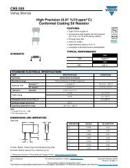
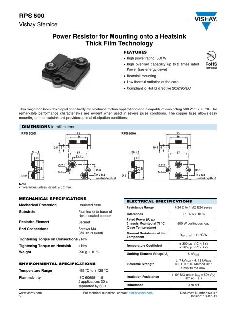
<strong>RPS</strong> <strong>500</strong><br />
Vishay Sfernice<br />
<strong>Power</strong> <strong>Resistor</strong> <strong>for</strong> <strong>Mounting</strong> <strong>onto</strong> a <strong>Heatsink</strong><br />
Thick Film Technology<br />
FEATURES<br />
� High power rating: <strong>500</strong> W<br />
� High overload capability up to 2 times rated<br />
<strong>Power</strong> (see energy curve)<br />
� <strong>Heatsink</strong> mounting<br />
� Low thermal radiation of the case<br />
� Compliant to RoHS directive 2002/95/EC<br />
This range has been developed specifically <strong>for</strong> electrical traction applications and is capable of dissipating <strong>500</strong> W at + 70 °C. The<br />
remarkable per<strong>for</strong>mance characteristics are evident when used in severe pulse conditions. The copper base allows easy<br />
mounting on the heatsink and provides optimal dissipation conditions.<br />
DIMENSIONS in millimeters<br />
<strong>RPS</strong> <strong>500</strong>D 73<br />
<strong>RPS</strong> <strong>500</strong>A 73<br />
56<br />
56<br />
Ø 21<br />
26 ± 1<br />
60<br />
10.5<br />
Ø 7.2<br />
Ø 4.2<br />
Note<br />
Tolerances unless stated: ± 0.2 mm<br />
57<br />
33.5<br />
MECHANICAL SPECIFICATIONS<br />
ENVIRONMENTAL SPECIFICATIONS<br />
6<br />
35.8<br />
2 x M4<br />
useful depth: 6<br />
Mechanical Protection Insulated case<br />
Substrate Alumina <strong>onto</strong> base of<br />
nickel coated copper<br />
Resistive Element Cermet<br />
End Connections Screws M4<br />
(M5 on request)<br />
Tightening Torque on Connections 2 Nm<br />
Tightening Torque on <strong>Heatsink</strong> 4 Nm<br />
Weight 250 g ± 10 %<br />
Temperature Range - 55 °C to + 125 °C<br />
Flammability IEC 60695-11-5<br />
2 applications 30 s<br />
separated by 60 s<br />
RoHS<br />
COMPLIANT<br />
www.vishay.com For technical questions, contact: sfer@vishay.com Document Number: <strong>500</strong>47<br />
58 Revision: 13-Jan-11<br />
Ø 21<br />
26 ± 1<br />
60<br />
10.5<br />
6<br />
Ø 7.2<br />
Ø 4.2<br />
ELECTRICAL SPECIFICATIONS<br />
57<br />
38.1<br />
2 x M4<br />
useful depth: 6<br />
Resistance Range 0.24 � to 1 M� E24 series<br />
Tolerances ± 1 % to ± 10 %<br />
Rated <strong>Power</strong> (Pr 70)<br />
Chassis Mounted at 70 °C <strong>500</strong> W continuous load<br />
(Case Temperature)<br />
Thermal Resistance of the<br />
Component<br />
Temperature Coefficient<br />
Limiting Element Voltage UL<br />
Dielectric Strength<br />
Insulation Resistance<br />
RTH (j - c): 0.11 °C/W<br />
± 300 ppm/°C < 1 �<br />
± 150 ppm/°C > 1 �<br />
5 kVRMS<br />
L: 7 kVRMS - H: 12 kVRMS<br />
MIL STD 202 Method 301:<br />
1 min/10 mA max.<br />
> 10 6 M� under Uins = <strong>500</strong> VDC<br />
IEC 60115-1<br />
Inductance < 50 nH
PERFORMANCE<br />
Note<br />
(1) <strong>Resistor</strong>s are not tested and guaranteed in cycling conditions<br />
<strong>Power</strong> <strong>Resistor</strong> <strong>for</strong> <strong>Mounting</strong> <strong>onto</strong> a <strong>Heatsink</strong><br />
Thick Film Technology<br />
TESTS CONDITIONS REQUIREMENTS<br />
Momentary Overload<br />
Rapid Temperature Change<br />
Load Life (Chassis Mounted)<br />
Humidity (Steady State)<br />
<strong>RPS</strong> <strong>500</strong><br />
Vishay Sfernice<br />
RECOMMENDATIONS FOR MOUNTING ONTO A HEATSINK<br />
� Surfaces in contact must be carefully cleaned.<br />
� The heatsink must have an acceptable flatness: From 0.05 mm to 0.1 mm/100 mm.<br />
� Roughness of the heatsink must be around 6.3 µm. In order to improve thermal conductivity, surfaces in contact (alumina,<br />
heatsink) should be coated with a silicone grease (type SI 340 from Rhône-Poulenc or Dow 340 from Dow Corning).<br />
� The fastening of the resistor to the heatsink is under pressure control of two screws tightened at 4 Nm <strong>for</strong> full power availability.<br />
� The following accessories are supplied with each product: 2 off CHC M4 x 16/16 class 8.8 <strong>for</strong> heatsink mounting,<br />
2 off TH M4 x 6/6 and 2 M4 contact lock washers <strong>for</strong> connections.<br />
CHOICE OF THE HEATSINK<br />
The user must choose according to the working conditions of the component (power, room temperature).<br />
Maximum working temperature must not exceed 125 °C.<br />
The dissipated power is simply calculated by the following ratio:<br />
P: Expressed in W<br />
IEC 60115-1<br />
2 Pr/10 s UL = <strong>500</strong>0 V<br />
IEC 60115-1/IEC60068-2-14 Test Na<br />
5 cycles - 55 °C to + 125 °C<br />
IEC 60115-1<br />
Pr (i.e. <strong>500</strong> W)/1000 h/70 °C (no cycling) (1)<br />
MIL STD 202 Method 103 B and D<br />
56 days 95% RH/40 °C<br />
RESISTANCE VALUE IN RELATION TO TOLERANCE AND TCR<br />
�T: Difference between maximum working temperature and room temperature.<br />
< ± (0.25 % + 0.05 �)<br />
< ± (0.25 % + 0.05 �)<br />
< ± (0.5 % + 0.05 �)<br />
< ± (0.5 % + 0.05 �)<br />
Ohmic < 1 � > 1 �<br />
Standard Tolerance ± 5 % ± 5 %<br />
Standard TCR (- 55 °C to + 125 °C) ± 300 ppm/°C ± 150 ppm/°C<br />
Tolerance on Request ± 1 %, ± 2 %, ± 10 %<br />
Tightening Torque on <strong>Heatsink</strong><br />
�T<br />
P =<br />
------------------------------------------------------------<br />
�RTH �j– c�<br />
+ RTH �c– a��<br />
<strong>RPS</strong> <strong>500</strong><br />
4 Nm<br />
RTH (j - c): Thermal resistance value measured between resistive layer and outer side of the resistor. It is the thermal<br />
resistance of the component: 0.11 °C/W.<br />
RTH (c - a): Thermal resistance value measured between outer side of the resistor and room temperature. It is the thermal<br />
resistance of the heatsink, depending on the heatsink itself (type, shape) and the quality of the fastening device.<br />
Document Number: <strong>500</strong>47 For technical questions, contact: sfer@vishay.com www.vishay.com<br />
Revision: 13-Jan-11 59
<strong>RPS</strong> <strong>500</strong><br />
Vishay Sfernice<br />
OVERLOADS<br />
Short time overload: 2 Pn/10 s<br />
Accidental overload: The values indicated in the graph below<br />
are applicable to resistors in air or mounted <strong>onto</strong> a heatsink.<br />
10 000<br />
ENERGY IN J<br />
1000<br />
100<br />
10<br />
1<br />
10 -7 10 -6<br />
10 -5<br />
10 -4<br />
MARKING<br />
Series, style, ohmic value (in �), tolerance (in %),<br />
manufacturing date, Vishay Sfernice trademark.<br />
<strong>Power</strong> <strong>Resistor</strong> <strong>for</strong> <strong>Mounting</strong> <strong>onto</strong> a <strong>Heatsink</strong><br />
Thick Film Technology<br />
10 -3<br />
10 -2<br />
OVERLOAD DURATION IN s<br />
ORDERING INFORMATION<br />
10 -1<br />
1<br />
POWER RATING<br />
The heatsink temperature should be maintained at the<br />
values specified in fig. 2.<br />
To optimise the thermal conduction, contacting surfaces<br />
should be coated with silicone grease and heatsink mounting<br />
screws tightened to 4 Nm.<br />
www.vishay.com For technical questions, contact: sfer@vishay.com Document Number: <strong>500</strong>47<br />
60 Revision: 13-Jan-11<br />
RATED POWER IN %<br />
100<br />
80<br />
60<br />
40<br />
20<br />
0<br />
0 20 40 60 80 100 120 140<br />
PACKAGING<br />
Box of 15 units<br />
HEATSINK TEMPERATURE IN °C<br />
<strong>RPS</strong> <strong>500</strong> DH 100 � 10 % XXX BO15 e<br />
MODEL STYLE CONNECTIONS<br />
Optional<br />
H: Dielectric<br />
strength 12 kV<br />
L: Dielectric<br />
strength 7 kV<br />
SAP PART NUMBERING GUIDELINES<br />
GLOBAL<br />
MODEL<br />
<strong>RPS</strong><strong>500</strong> D = Diagonal<br />
connections<br />
A = Straight<br />
connections<br />
RESISTANCE VALUE TOLERANCE<br />
± 1 %<br />
± 2 %<br />
± 5 %<br />
± 10 %<br />
CUSTOM DESIGN<br />
Options<br />
on request<br />
TCR, shape,<br />
etc.<br />
PACKAGING LEAD (Pb)-FREE<br />
R P S 0 5 0 0 D H 4 7 R 0 J B<br />
STYLE DIELECTRIC OHMIC VALUE TOLERANCE PACKAGING SPECIAL<br />
H = Dielectric<br />
strength 12 kV<br />
L = Dielectric<br />
strength 7 kV<br />
The first four digits are<br />
significant figures and the<br />
last digit specifies the<br />
number of zeros to follow.<br />
R designates decimal point.<br />
48R70 = 48.7 �<br />
47R0 = 47 �<br />
1001 = 1 k�<br />
4R70 = 4.7 �<br />
R240 = 0.24��<br />
F = 1 %<br />
G = 2 %<br />
J = 5 %<br />
K = 10 %<br />
B = Box 15 pieces<br />
N = Box 15 pieces<br />
N/A (1 to 14 pieces<br />
by Box)<br />
As applicable<br />
ZAx.
www.vishay.com<br />
Disclaimer<br />
Legal Disclaimer Notice<br />
Vishay<br />
ALL PRODUCT, PRODUCT SPECIFICATIONS AND DATA ARE SUBJECT TO CHANGE WITHOUT NOTICE TO IMPROVE<br />
RELIABILITY, FUNCTION OR DESIGN OR OTHERWISE.<br />
Vishay Intertechnology, Inc., its affiliates, agents, and employees, and all persons acting on its or their behalf (collectively,<br />
“Vishay”), disclaim any and all liability <strong>for</strong> any errors, inaccuracies or incompleteness contained in any datasheet or in any other<br />
disclosure relating to any product.<br />
Vishay makes no warranty, representation or guarantee regarding the suitability of the products <strong>for</strong> any particular purpose or<br />
the continuing production of any product. To the maximum extent permitted by applicable law, Vishay disclaims (i) any and all<br />
liability arising out of the application or use of any product, (ii) any and all liability, including without limitation special,<br />
consequential or incidental damages, and (iii) any and all implied warranties, including warranties of fitness <strong>for</strong> particular<br />
purpose, non-infringement and merchantability.<br />
Statements regarding the suitability of products <strong>for</strong> certain types of applications are based on Vishay’s knowledge of typical<br />
requirements that are often placed on Vishay products in generic applications. Such statements are not binding statements<br />
about the suitability of products <strong>for</strong> a particular application. It is the customer’s responsibility to validate that a particular<br />
product with the properties described in the product specification is suitable <strong>for</strong> use in a particular application. Parameters<br />
provided in datasheets and/or specifications may vary in different applications and per<strong>for</strong>mance may vary over time. All<br />
operating parameters, including typical parameters, must be validated <strong>for</strong> each customer application by the customer’s<br />
technical experts. Product specifications do not expand or otherwise modify Vishay’s terms and conditions of purchase,<br />
including but not limited to the warranty expressed therein.<br />
Except as expressly indicated in writing, Vishay products are not designed <strong>for</strong> use in medical, life-saving, or life-sustaining<br />
applications or <strong>for</strong> any other application in which the failure of the Vishay product could result in personal injury or death.<br />
Customers using or selling Vishay products not expressly indicated <strong>for</strong> use in such applications do so at their own risk and agree<br />
to fully indemnify and hold Vishay and its distributors harmless from and against any and all claims, liabilities, expenses and<br />
damages arising or resulting in connection with such use or sale, including attorneys fees, even if such claim alleges that Vishay<br />
or its distributor was negligent regarding the design or manufacture of the part. Please contact authorized Vishay personnel to<br />
obtain written terms and conditions regarding products designed <strong>for</strong> such applications.<br />
No license, express or implied, by estoppel or otherwise, to any intellectual property rights is granted by this document or by<br />
any conduct of Vishay. Product names and markings noted herein may be trademarks of their respective owners.<br />
Material Category Policy<br />
Vishay Intertechnology, Inc. hereby certifies that all its products that are identified as RoHS-Compliant fulfill the<br />
definitions and restrictions defined under Directive 2011/65/EU of The <strong>Europe</strong>an Parliament and of the Council<br />
of June 8, 2011 on the restriction of the use of certain hazardous substances in electrical and electronic equipment<br />
(EEE) - recast, unless otherwise specified as non-compliant.<br />
Please note that some Vishay documentation may still make reference to RoHS Directive 2002/95/EC. We confirm that<br />
all the products identified as being compliant to Directive 2002/95/EC con<strong>for</strong>m to Directive 2011/65/EU.<br />
Revision: 12-Mar-12 1 Document Number: 91000