NSK Linear Guides - NSK Americas
NSK Linear Guides - NSK Americas
NSK Linear Guides - NSK Americas

Create successful ePaper yourself
Turn your PDF publications into a flip-book with our unique Google optimized e-Paper software.
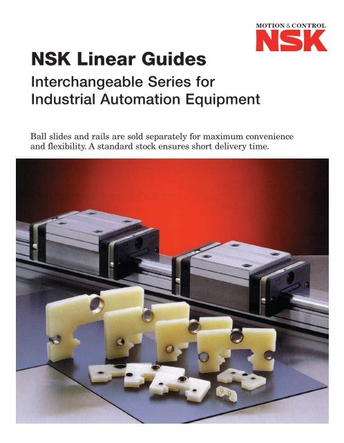
<strong>NSK</strong> <strong>Linear</strong> <strong>Guides</strong><br />
Interchangeable Series for<br />
Industrial Automation Equipment<br />
Ball slides and rails are sold separately for maximum convenience<br />
and flexibility. A standard stock ensures short delivery time.
• Five Types Available in Commercial Grade<br />
• LE Series Miniature - Wide Type<br />
• LH Series for High Load Capacity Applications<br />
• LS Series for Compact Low Profile Space Saving Conditions<br />
• LU Series Miniature Type<br />
• LW Series Wide Type<br />
• Interchangeable Rails and Ball Slides<br />
• Preload and Clearance Types Available<br />
• Fluoride Black Chrome Plated Rails and Ball Slides<br />
• Large Inventory for Prompt Delivery<br />
How to Use This Guide . . . . . . . . . . . . . . . . . . . . . . . . . . . . . . . . . . . . . . . . . . . . . . . . . . . . . . . . . . . . . . . . . . . . . . . . . . 3<br />
Features . . . . . . . . . . . . . . . . . . . . . . . . . . . . . . . . . . . . . . . . . . . . . . . . . . . . . . . . . . . . . . . . . . . . . . . . . . . . . . . . . . . . . . 3<br />
Interchange . . . . . . . . . . . . . . . . . . . . . . . . . . . . . . . . . . . . . . . . . . . . . . . . . . . . . . . . . . . . . . . . . . . . . . . . . . . . . . . . . . . 4<br />
Identification Numbers – ‘LH’ Series . . . . . . . . . . . . . . . . . . . . . . . . . . . . . . . . . . . . . . . . . . . . . . . . . . . . . . . . . . . . . . . . 6<br />
Accuracy Standard – ‘LH’ Series Load Rating and Life Calculation . . . . . . . . . . . . . . . . . . . . . . . . . . . . . . . . . . . . . . . . 7<br />
Dimensional Tables – ‘LH’ Ball Slides . . . . . . . . . . . . . . . . . . . . . . . . . . . . . . . . . . . . . . . . . . . . . . . . . . . . . . . . . . . . . . . 8<br />
Dimensional Tables – ‘LH’ Series Rails . . . . . . . . . . . . . . . . . . . . . . . . . . . . . . . . . . . . . . . . . . . . . . . . . . . . . . . . . . . . . 12<br />
Accessories – ‘LH’ Series . . . . . . . . . . . . . . . . . . . . . . . . . . . . . . . . . . . . . . . . . . . . . . . . . . . . . . . . . . . . . . . . . . . . . . . 13<br />
Identification Numbers – ‘LS’ Series . . . . . . . . . . . . . . . . . . . . . . . . . . . . . . . . . . . . . . . . . . . . . . . . . . . . . . . . . . . . . . . 14<br />
Accuracy Standard – ‘LS’ Series Load Rating and Life Calculation . . . . . . . . . . . . . . . . . . . . . . . . . . . . . . . . . . . . . . . 15<br />
Dimensional Tables – ‘LS’ Series Ball Slides . . . . . . . . . . . . . . . . . . . . . . . . . . . . . . . . . . . . . . . . . . . . . . . . . . . . . . . . . 16<br />
Dimensional Tables – ‘LS’ Series Rails . . . . . . . . . . . . . . . . . . . . . . . . . . . . . . . . . . . . . . . . . . . . . . . . . . . . . . . . . . . . . 20<br />
Accessories – ‘LS’ Series. . . . . . . . . . . . . . . . . . . . . . . . . . . . . . . . . . . . . . . . . . . . . . . . . . . . . . . . . . . . . . . . . . . . . . . . 21<br />
Identification Numbers – ‘LU’ Series . . . . . . . . . . . . . . . . . . . . . . . . . . . . . . . . . . . . . . . . . . . . . . . . . . . . . . . . . . . . . . . 22<br />
Identification Numbers – ‘LE’ Series . . . . . . . . . . . . . . . . . . . . . . . . . . . . . . . . . . . . . . . . . . . . . . . . . . . . . . . . . . . . . . . 23<br />
Identification Numbers – ‘LW’ Series . . . . . . . . . . . . . . . . . . . . . . . . . . . . . . . . . . . . . . . . . . . . . . . . . . . . . . . . . . . . . . . 24<br />
Assembly and Mounting Method . . . . . . . . . . . . . . . . . . . . . . . . . . . . . . . . . . . . . . . . . . . . . . . . . . . . . . . . . . . . . . . . . . 25<br />
Lubrication & Grease Fittings. . . . . . . . . . . . . . . . . . . . . . . . . . . . . . . . . . . . . . . . . . . . . . . . . . . . . . . . . . . . . . . . . . . . . 26<br />
Grease Units. . . . . . . . . . . . . . . . . . . . . . . . . . . . . . . . . . . . . . . . . . . . . . . . . . . . . . . . . . . . . . . . . . . . . . . . . . . . . . . . . . 27<br />
Application Sheet – Rail Butting . . . . . . . . . . . . . . . . . . . . . . . . . . . . . . . . . . . . . . . . . . . . . . . . . . . . . . . . . . . . . . . . . . 31<br />
K1 Maintenance-Free Lubrication Units. . . . . . . . . . . . . . . . . . . . . . . . . . . . . . . . . . . . . . . . . . . . . . . . . . . . . . . . . . . 32<br />
Identification Numbers – K1 Maintenance-Free Lubrication Units . . . . . . . . . . . . . . . . . . . . . . . . . . . . . . . . . . . . . . 33<br />
K1 Lubrication Units Handling and Assembly Instructions . . . . . . . . . . . . . . . . . . . . . . . . . . . . . . . . . . . . . . . . . . . . 34<br />
Unit Conversion Chart . . . . . . . . . . . . . . . . . . . . . . . . . . . . . . . . . . . . . . . . . . . . . . . . . . . . . . . . . . . . . . . . . . . . . . . . . . 35<br />
2<br />
CAD DRAWING DATA<br />
CONTENTS<br />
For LE/LH/LS/LU & LW-Series go to <strong>NSK</strong> technical website www.npa.nsk.com<br />
For 3D IGES files on CD-ROM of LH/LS-Series <strong>Linear</strong> <strong>Guides</strong> email info@npa.nsk.com<br />
Note: CAD DXF drawing files are also available for other linear motion products. Contact <strong>NSK</strong>.<br />
PAGE
How to Use this Guide<br />
Use this guide to select the linear guide ball slides, rails and accessories that you need for your application.<br />
Pages 6, 14, 22, 23, 24 and 33 provide identification numbers that you will need to order the components<br />
for your application.<br />
If you have any uncertainties, or would like more detailed information about any aspect of linear guides,<br />
please contact your <strong>NSK</strong> representative at one of our locations listed on the back cover.<br />
FEATURES<br />
Interchangeability of Rail and Ball Slide<br />
One important manufacturing feature of the Gothic Arch is the ability to make highly accurate measurements<br />
on both the ball slide and rail, allowing for tight tolerance control, resulting in interchangeability. This means<br />
that additions and/or replacement of ball slides is easily done.<br />
High Load Capacity and Long Life<br />
<strong>NSK</strong> has developed an infinite ball recirculating type linear guide with the largest load capacity available (comparing<br />
equal size ball slides). This high load capability helps to ensure long life.<br />
Compact Low Profile Type<br />
To minimize space, <strong>NSK</strong> has developed low profile linear guides to handle various applications.<br />
Miniature and Miniature Wide Type Stainless Steel<br />
If light loads and corrosive conditions are present for your application needs, <strong>NSK</strong> can supply a miniature and<br />
miniature wide type linear guide in stainless steel. <strong>NSK</strong>’s built-in ball retainer system allows for easy installation<br />
and removal of ball slides.<br />
Wide Type<br />
If your application requires low profile combined with high load, <strong>NSK</strong> offers the wide series linear guides.<br />
Shock Resistant Design<br />
Another design feature of the Gothic arch is its ability to<br />
absorb vertical shock loads from above using four-row<br />
groove configuration. This design is favorable in case of<br />
unexpected accidents during installation, or the operation of<br />
equipment. The ball groove is designed to avoid edge<br />
loading under extreme loads, extending the life of the unit.<br />
Universal Slider<br />
<strong>NSK</strong> has incorporated both thru and tapped holes into one flanged slider for a combination of mounting<br />
applications. (EM/EMZ replaces EL/ELZ and FL/FLZ • GM/GMZ replaces HL/HLZ and GL/GLZ)<br />
Ability to Butt Rails<br />
Tolerance of ball grooves on the ball slides and rails are controlled to allow for butting, giving you the flexibility<br />
of unlimited lengths. We can offer a stocked linear guide rail with versatility in assembling preloaded or clearance<br />
type ball slides.<br />
K1 Maintenance-Free Lubrication Units<br />
<strong>NSK</strong> has the K1 Lubrication Units for all five series of interchangeable linear guides. These K1 Lubrication Units<br />
are all available from stock.<br />
Maximum Rail Length in One Section Available up to 4,000 mm.<br />
DF Arrangement<br />
2 point contact<br />
Normal load is carried on the top two grooves.<br />
Shock load is carried by all four grooves.<br />
Short Delivery Time<br />
We can ship from our large inventory, both standard and custom cut-to-length linear rails.<br />
Normal Load Shock Load<br />
Fluoride Low Temperature Chrome Plating<br />
<strong>NSK</strong> has a plating for linear bearings and rails to cover conditions requiring wet, corrosive and clean room<br />
applications. <strong>NSK</strong> also uses industry approved armaloy coating. These are available from stock.<br />
3
Interchange – <strong>Linear</strong> Guide<br />
(LH & LS Series)<br />
4<br />
DESCRIPTION<br />
CARRIAGE PART NUMBER<br />
RAIL PART NUMBER<br />
ASSEMBLY PART NUMBER<br />
INTERCHANGE<br />
<strong>NSK</strong> THK THOMSON<br />
LAH 20 AN Z HSR 20 R CG 20 CE<br />
1 2 3 7 1 2 3 1 2 3<br />
L1H 20 XXXX HSR 20+ XXXXL RG 20 N LXXXX<br />
1 2 4 1 2 4 1 2 4<br />
The competitive manufacturers are provided for a convenient source of unit substitution. They can be considered interchangeable in most instances,<br />
but for special applications, please consult <strong>NSK</strong> Engineering. <strong>NSK</strong> assumes no liability with respect to errors or omissions.<br />
<strong>NSK</strong><br />
<strong>NSK</strong><br />
*THOMSON NOT DIMENSIONALLY EQUIVALENT, MAY NEED SHIM<br />
LH 20 XXXX AN 2 PC Z HSR 20 R 2 SS C1 +XXXXL P<br />
1 2 4 3 5 6 7 1 2 3 5 8 7 4 6<br />
1-<strong>Linear</strong> Guide Series<br />
THK THOMSON<br />
LH HSR CG<br />
LS SR<br />
2-<strong>Linear</strong> Guide Size<br />
THK THOMSON<br />
LH15 HSR15<br />
LH20 HSR20 CG20<br />
LH25 HSR25 CG25<br />
LH30 HSR30 CG30<br />
LH35 HSR35 CG35<br />
LH45 HSR45 CG45<br />
LH55 HSR55 CG55<br />
LH65 HSR65<br />
LS15 SR15<br />
LS20 SR20<br />
LS25 SR25<br />
LS30 SR30<br />
LS35 SR35<br />
<strong>NSK</strong><br />
<strong>NSK</strong><br />
<strong>Linear</strong> <strong>Guides</strong> are designed for high precision motion and control applications.<br />
They provide greater rigidity and higher load capacity than shaft and bushing designs.<br />
Some of the industries served - machine tool, robotics, medical and aerospace –<br />
require smooth travel and high accuracy.<br />
3-<strong>Linear</strong> Guide Carriage Styles<br />
LH Series<br />
THK THOMSON<br />
LAH##AN HSR##TR/TRX/CR/R CG##CE<br />
LAH##BN HSR##HTR/HR/LR CG##DE<br />
LAH##EM HSR##TA/CA/A<br />
HSR##TB/CB/B<br />
CGAA<br />
LAH##GM HSR##HTA/HA/LA<br />
HTB/HB/LB<br />
CG##BA<br />
LAS##FL SR##TB/TBY<br />
LAS##AL SR##TX/W/WY<br />
LAS##KL SR##SB/SBY<br />
LAS##CL SR##SX/V/VY<br />
LS Series<br />
THK THOMSON<br />
INTERCHANGE = LAH or LAS FOLLOWED BY<br />
SERIES# + CARRIAGE STYLE<br />
<strong>NSK</strong><br />
<strong>NSK</strong><br />
4-<strong>Linear</strong> Guide Rail Length mm<br />
THK THOMSON<br />
L1H##XXXX HSR##+XXXXL RG##NLXXXX<br />
L1S##XXXX HSR##+XXXXL<br />
5-Carriages Per Rail<br />
Number following carriage style<br />
= number of carriages per rail<br />
6-Accuracy Class<br />
THK THOMSON<br />
PC N<br />
P6 H H<br />
P5 P P<br />
P4 SP S<br />
P3 UP U<br />
<strong>NSK</strong><br />
<strong>NSK</strong><br />
7-Preload (assemblies only)<br />
THK THOMSON<br />
T A<br />
Z C1 B<br />
2 C1 B<br />
3 C0 C<br />
4 C0 C<br />
<strong>NSK</strong><br />
7-Preload (interchangeable car-<br />
THK THOMSON<br />
Z C1 B<br />
8-Seals<br />
THK THOMSON<br />
Standard with side SS-end/bottom<br />
and bottom seals. UU-end LDS<br />
Double seals and ZZ-end/bottom/protector ZZ<br />
protectors available. DD-double/bottom DD<br />
KK-double/bottom/protector KK
Interchange – <strong>Linear</strong> Guide<br />
(LU, LE & LW Series)<br />
DESCRIPTION<br />
CARRIAGE PART NUMBER<br />
RAIL PART NUMBER<br />
ASSEMBLY PART NUMBER<br />
INTERCHANGE<br />
<strong>NSK</strong> THK THOMSON<br />
LAU 15 AL RSR 15 M CD 15 AA<br />
LAE 12 AR RSR 12 W 1 2 3<br />
LAW 17 EL HRW 17 CA<br />
1 2 3 1 2 3 1 2 3<br />
L1U 15 XXXX RSR 15 +XXXXL RD 15 LXXXX<br />
L1E 12 XXXX RSR 12W +XXXXL<br />
L1W 17 XXXX HRW 17 +XXXXL<br />
1 2 4 1 2 4 1 2 4<br />
LU 15 XXXX AL 2 PC ZT 2 RSR 15 R UU C1 +XXXXL P<br />
LE 12 XXXX AR 2 PC ZT 2 RSR 12 W UU C1 +XXXXL P<br />
1 2 4 3 5 6 7 5 1 2 3 8 7 4 6<br />
LW 17 XXXX EL 2 PC ZT HRW 17 CA 2 UU C1 +XXXXL P<br />
1 2 4 3 5 6 7 1 2 3 5 8 7 4 6<br />
The competitive manufacturers are provided for a convenient source of unit substitution. They can be considered interchangeable in most instances,<br />
but for special applications, please consult <strong>NSK</strong> Engineering. <strong>NSK</strong> assumes no liability with respect to errors or omissions.<br />
<strong>NSK</strong><br />
<strong>NSK</strong><br />
1-<strong>Linear</strong> Guide Series<br />
THK THOMSON<br />
LU RSR CD<br />
LE RSR W<br />
LW HRW<br />
2-<strong>Linear</strong> Guide Size<br />
THK THOMSON<br />
LU05<br />
LU07 RSR07<br />
LU09 RSR09<br />
LU12 RSR12 CD10<br />
LU15 RSR15 CD15<br />
LE09 RSR09W CD20<br />
LE12 RSR12W<br />
LE15 RSR15W<br />
LW17 HRW17<br />
LW21 HRW21<br />
LW27 HRW27<br />
LW35 HRW35<br />
LW50 HRW50<br />
<strong>NSK</strong><br />
3-<strong>Linear</strong> Guide Carriage Styles<br />
LU & LE Series<br />
THK THOMSON<br />
LAU/LAE##AR, AL RSR/RSRW##M,KM,WM,WVM CD##AA<br />
LAU/LAE##TR, TL RSR/RSRW##VM,M,KM<br />
LAU/LAE##BL, UL<br />
LAU/LAE##CL, SL<br />
RSR/RSRW##WN,N<br />
<strong>NSK</strong><br />
THK<br />
LS Series<br />
THOMSON<br />
LAW##EL HRW##CA<br />
INTERCHANGE = LAU, LAE, LAW FOLLOWED BY<br />
SERIES # + CARRIAGE STYLE<br />
<strong>NSK</strong><br />
<strong>NSK</strong><br />
4-<strong>Linear</strong> Guide Rail Length mm<br />
THK THOMSON<br />
L1U ## XXXX RSR##+XXXXL RD##LXXXX<br />
L1E ## XXXX RSR##W+XXXXL<br />
L1W ## XXXX HRW##+XXXXL<br />
5-Carriages Per Rail<br />
Number following carriage style<br />
= number of carriages per rail<br />
6-Accuracy Class<br />
THK THOMSON<br />
PC N<br />
P6 H H<br />
P5 P P<br />
P4 SP S<br />
P3 UP U<br />
<strong>NSK</strong><br />
<strong>NSK</strong><br />
7-Preload (assemblies only)<br />
THK THOMSON<br />
T A<br />
Z C1 B<br />
2 C1 B<br />
3 C0 C<br />
4 C0 C<br />
<strong>NSK</strong><br />
7-Preload (interchangeable car-<br />
THK THOMSON<br />
Z C1 B<br />
8-Seals<br />
THK THOMSON<br />
Standard with side SS-end/bottom<br />
and bottom seals. UU-end LDS<br />
Double seals and ZZ-end/bottom/protector ZZ<br />
protectors available. DD-double/bottom DD<br />
KK-double/bottom/protector KK<br />
5
LH Series<br />
Identification Number Ball Slide<br />
6<br />
Ball Slide Type<br />
Ball Slide (Stocked item)<br />
LAH 25 AN Z - K<br />
Size No.<br />
AN: Square - Standard<br />
AL: Square - Short height standard<br />
BN: Square - Long<br />
BL: Square - Short height long<br />
EM: Flanged (Tapped & Thru hole) Standard<br />
GM: Flanged (Tapped & Thru hole) Long<br />
Style<br />
Material Code<br />
No Code: Standard Carbon Steel (May also be C)<br />
S: Stainless Steel (Standard for LU and LE Series)<br />
D: Carbon Steel + Fluoride Coating<br />
H: Stainless Steel + Fluoride Coating<br />
A: Carbon Steel + Armoloy Coating<br />
B: Stainless Steel + Armoloy Coating<br />
Flanged Type Low Height Type With Tapped & Thru Holes<br />
No Code: No special accessories and fluoride black chrome plating<br />
K: One K1 Lubrication Unit each side<br />
K2: Two K1 Lubrication Units each side<br />
D: Double Seals each side<br />
P: Protector Plate each side<br />
No Code: Clearance Type<br />
Z: Preloaded Type<br />
EM (High Load)<br />
GM (Ultra High Load)<br />
Square Type High Type LH-AN (High Load), LH-BN (Ultra High Load)<br />
Fig.-1 LH-AN, LH-BN TYPE Fig.-2 LH-EM, LH-GM TYPE<br />
Internal Clearance and Preload<br />
The internal clearance refers to the amount of movement of the ball slide, when moved up and down with the rail fixed.<br />
The amount of preload is specified by size as follows.<br />
Table 1 Unit: µm<br />
Size #15 #20 #25 #30 #35 #45 #55 #65<br />
Clearance 15~–4 15~–5<br />
Preloaded 0~–4 0~–5 0~–7 0~–9
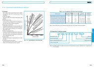
Accuracy Standard<br />
The accuracy standard of the <strong>NSK</strong> “High Load<br />
Capacity LH-Series” is shown in Table 1. With highaccuracy<br />
control of individual rail size and<br />
interchangeability, the accuracy of Table 1 can be<br />
maintained sufficiently even after addition or<br />
replacement of the ball slide.<br />
Table 1 Tolerances Unit : µm<br />
(For Clearance Preload Type)<br />
Tolerances<br />
Model No. LH<br />
(See Fig. 4 for Symbols) 15, 20, 25, 30, 35 45,55,65<br />
Mounting Height H ±20 ±30<br />
Variation of Mounting Height H<br />
15 (1) 20 (1)<br />
30 (2)<br />
35 (2)<br />
Mounting Width W 2 or W 2 ±30 ±30<br />
Variation of Mounting Width W 2 or W 2 ±25 ±30<br />
Running Parallelism of Face C to Face A Refer to<br />
Running Parallelism of Face D to Face B<br />
Fig. 3<br />
W 2 is applicable to the reference side only. Note: during installation the reference<br />
side is indicated by a line provided on the side of ball slide and rail. (See Fig. 4)<br />
1. Variation on the same rail.<br />
2. Variation on multiple rails.<br />
Fig.-3 Running Parallelism<br />
Running Parallelism ( m)<br />
50<br />
40<br />
30<br />
20<br />
10<br />
0<br />
1000 2000 3000 4000<br />
Overall Rail Length (mm)<br />
Fig.-4 Accuracy Standard<br />
Load Rating and Life<br />
The LH-Series is based on a design applying load<br />
from above. Therefore the dimension table shows the<br />
basic dynamic load rating C and basic static load<br />
rating C 0 for the downward direction. If the load is<br />
applied laterally or upward refer to values in Table 2.<br />
Table 2 Basic Load Rating Correction for Direction<br />
Load Direction<br />
Basic Dynamic<br />
Load Rating<br />
Downward C C 0<br />
Upward C 0.75C 0<br />
Laterally 0.88C 0.63C 0<br />
Estimate the life of linear guides using the equation below.<br />
Fig.-5<br />
C 3<br />
L = 50( ) fW•F<br />
where, L : Rated fatigue life (km)<br />
C : Basic dynamic load rating (N)<br />
F : Load to a ball slide (N)<br />
(Dynamic equivalent load)<br />
fW : Load factor<br />
Basic Static<br />
Load Rating<br />
f W =1.0 ~ 1.2 (Smooth condition)<br />
f W =1.2 ~ 1.5 (Normal condition)<br />
f W =1.5 ~ 3.0 (With shock or vibration)<br />
7
LH Series<br />
Ball Slide Dimension Table<br />
8<br />
Square Type<br />
LAH-AN/ANZ<br />
-AL/ALZ<br />
LAH-BN/BNZ<br />
-BL/BLZ<br />
Model No.<br />
LAH15 AN/ANZ<br />
LAH15 BN/BNZ<br />
Ass’y Dimensions Ball Slide Dimensions<br />
H E W 2 W B L L 1 J J 1 K T M x pitch x l<br />
28 4.6 9.5 34 26 55 39 26 6.5 23.4 8 M4 x 0.7 x 6<br />
LAH20 AN/ANZ 69.8 50 36 7<br />
30 5 12 44 32<br />
LAH20 BN/BNZ<br />
91.8 72 50 11<br />
25 12 M5 x 0.8 x 6<br />
LAH25 AL/ALZ 36 M6 x 1 x 6<br />
LAH25 AN/ANZ<br />
LAH25 BL/BLZ<br />
40<br />
36<br />
7 12.5 48 35<br />
79 58 35 11.5<br />
33 12<br />
M6 x 1 x 9<br />
M6 x 1 x 6<br />
LAH25 BN/BNZ 40<br />
107 86 50 18<br />
M6 x 1 x 9<br />
LAH30 AL/ALZ 42 M8 x 1.25 x 8<br />
LAH30 AN/ANZ<br />
LAH30 BL/BLZ<br />
45<br />
42<br />
9 16 60 40<br />
85.6 59 40 9.5<br />
36 14<br />
M8 x 1.25 x 10<br />
M8 x 1.25 x 8<br />
LAH30 BN/BNZ 45<br />
124.6 98 60 19<br />
M8 x 1.25 x 10<br />
LAH35 AL/ALZ 48 M8 x 1.25 x 8<br />
LAH35 AN/ANZ<br />
LAH35 BL/BLZ<br />
55<br />
48<br />
9.5 18 70 50<br />
109 80 50 15<br />
45.5 15<br />
M8 x 1.25 x 12<br />
M8 x 1.25 x 8<br />
LAH35 BN/BNZ 55<br />
143 114 72 21<br />
M8 x 1.25 x 8<br />
LAH45 AN/ANZ 139 105 60 22.5<br />
70 14 20.5 86 60<br />
LAH45 BN/BNZ<br />
171 137 80 28.5<br />
LAH55 AN/ANZ 163 126 75 25.5<br />
80 15 23.5 100 75<br />
LAH55 BN/BNZ<br />
201 164 95 34.5<br />
LAH65 AN/ANZ 193 147 70 38.5<br />
90 16 31.5 126 76<br />
LAH65 BN/BNZ<br />
253 207 120 48.5<br />
Note: W 1 rail dimensions are on Page 12.<br />
56 17 M10 x 1.5 x 17<br />
65 18 M12 x 1.75 x 18<br />
74 23 M16 x 2 x 20
Grease Fitting Basic Load Ratings<br />
Mounting Hole<br />
Dynamic Static Static Moment (N•m)<br />
Thread Spec.<br />
T1 N<br />
C (N) C0 (N) MRO MPO MYO ø3 (thru hole) 8.5 3.3<br />
M6 x 0.75 5 11<br />
M6 x 0.75 10 11<br />
M6 x 0.75 10 11<br />
M6 x 0.75 15 11<br />
PT1/8 20 13<br />
PT1/8 21 13<br />
PT1/8 19 13<br />
Refer to<br />
pages 32 to 34 regarding<br />
technical information for<br />
the K1 Maintenance-Free<br />
Lubrication Unit<br />
Weight<br />
(kg)<br />
Unit : mm<br />
Model No.<br />
10800 20700 108 95 80 0.18 LAH15 AN/ANZ<br />
14600 32000 166 216 181 0.33 LAH15 BN/BNZ<br />
17400 32500 219 185 155 0.48 LAH20 AN/ANZ<br />
23500 50500 340 420 355 0.55 LAH20 BN/BNZ<br />
25600 46000 360 320 267 0.55<br />
LAH25 AL/ALZ<br />
LAH25 AN/ANZ<br />
LAH25 BL/BLZ<br />
34500 71000 555 725 610 0.82 LAH25 BN/BNZ<br />
31000 51500 490 350 292 0.77<br />
LAH30 AL/ALZ<br />
LAH30 AN/ANZ<br />
LAH30 BL/BLZ<br />
46000 91500 870 1030 865 1.3 LAH30 BN/BNZ<br />
47500 80500 950 755 630 1.5<br />
LAH35 AL/ALZ<br />
LAH35 AN/ANZ<br />
LAH35 BL/BLZ<br />
61500 117000 1380 1530 1280 2.1 LAH35 BN/BNZ<br />
81000 140000 2140 1740 1460 3 LAH45 AN/ANZ<br />
99000 187000 2860 3000 2520 3.9 LAH45 BN/BNZ<br />
119000 198000 3600 3000 2510 4.7 LAH55 AN/ANZ<br />
146000 264000 4850 5150 4350 6.1 LAH55 BN/BNZ<br />
181000 281000 6150 4950 4150 7.7 LAH65 AN/ANZ<br />
235000 410000 8950 8950 8450 10.8 LAH65 BN/BNZ<br />
9
LH Series<br />
Ball Slide Dimension Table<br />
10<br />
Flange Type<br />
LAH-EM/EMZ<br />
(formerly EL-ELZ-90)<br />
LAH-GM/GMZ<br />
(formerly GL-GLZ-90)<br />
LAH15<br />
LAH20<br />
LAH25<br />
LAH30<br />
LAH35<br />
4-Mxl Tapped hole<br />
Note: EM/EMZ and GM/GMZ is a combination of Tapped hole and Thru hole.<br />
Model No.<br />
LAH45<br />
LAH55<br />
LAH65<br />
Ass’y Dimensions Ball Slide Dimensions<br />
H E W 2 W B x J L L 1 J 1 K T M x pitch x I Ø Q x l<br />
EM/EMZ 55 39 4.5<br />
24 4.6 16 47 38 x 30<br />
GM/GMZ<br />
74 58 14<br />
EM/EMZ 69.8 50 5<br />
30 5 21.5 63 53 x 40<br />
GM/GMZ<br />
91.8 72 16<br />
EM/EMZ 79 58 6.5<br />
36 7 23.5 70 57 x 45<br />
GM/GMZ<br />
107 86 20.5<br />
EM/EMZ 98.6 72 10<br />
42 9 31 90 72 x 52<br />
GM/GMZ<br />
124.6 98 23<br />
EM/EMZ 109 80 9<br />
48 9.5 33 100 82 x 62<br />
GM/GMZ<br />
143 114 26<br />
EM/EMZ 139 105 12.5<br />
60 14 37.5 120 100 x 80<br />
GM/GMZ<br />
171 137 28.5<br />
EM/EMZ 163 126 15.5<br />
70 15 43.5 140 116 x 95<br />
GM/GMZ<br />
201 164 34.5<br />
EM/EMZ 193 147 18.5<br />
90 16 53.5 170 142 x 110<br />
GM/GMZ<br />
253 207 48.5<br />
Note: W 1 rail dimensions are on Page 12.<br />
(EM/EMZ replaces EL/ELZ and FL/FLZ • GM/GMZ replaces HL/HLZ and GL/GLZ)<br />
Bolt Size<br />
Through Hole Q<br />
19.4 8 M5 x 0.8 x 7 Ø4.4 x 8 M4<br />
25 10 M6 x 1 x 9.5 Ø5.3 x 10 M5<br />
29 11 M8 x 1.25 x 10 Ø6.8 x 10 M6<br />
33 11 M10 x 1.5 x 12 Ø8.6 x 12 M8<br />
38.5 12 M10 x 1.5 x 13 Ø8.6 x 13 M8<br />
46 13 M12 x 1.75 x 15 Ø10.5 x 15 M10<br />
55 15 M14 x 2 x 18 Ø12.5 x 18 M12<br />
74 23 M16 x 2 x 24 Ø14.6 x 24 M14
Grease Fitting Basic Load Ratings<br />
Mounting Hole<br />
Dynamic Static Static Moment (N•m)<br />
Thread Spec.<br />
T1 N<br />
C (N) C0 (N) MRO MPO MYO Ø3 (thru hole) 4.5 3.3<br />
M6 x 0.75 5 11<br />
M6 x 0.75 6 11<br />
M6 x 0.75 7 11<br />
M6 x 0.75 8 11.5<br />
PT1/8 10 13<br />
PT1/8 11 13<br />
PT1/8 19 13<br />
Refer to<br />
pages 32 to 34 regarding<br />
technical information for<br />
the K1 Maintenance-Free<br />
Lubrication Unit<br />
Weight<br />
(kg)<br />
Unit : mm<br />
Model No.<br />
10800 20700 108 95 80 0.17<br />
EM/EMZ<br />
LAH15<br />
14600 32000 166 216 181 0.25 GM/GMZ<br />
17400 32500 219 185 155 0.45<br />
EM/EMZ<br />
LAH20<br />
23500 50500 340 420 355 0.65 GM/GMZ<br />
25600 46000 360 320 267 0.63<br />
EM/EMZ<br />
LAH25<br />
34500 71000 555 725 610 0.93 GM/GMZ<br />
35500 63000 600 350 292 1.2<br />
EM/EMZ<br />
LAH30<br />
46000 91500 870 1030 865 1.6 GM/GMZ<br />
47500 80500 950 755 630 1.7<br />
EM/EMZ<br />
LAH35<br />
61500 117000 1380 1530 1280 2.4 GM/GMZ<br />
81000 140000 2140 1740 1460 3<br />
EM/EMZ<br />
LAH45<br />
99000 187000 2860 3000 2520 3.9 GM/GMZ<br />
119000 198000 3600 3000 2510 5<br />
EM/EMZ<br />
LAH55<br />
146000 264000 4850 5150 4350 6.5 GM/GMZ<br />
181000 281000 6150 4950 4150 10<br />
EM/EMZ<br />
LAH65<br />
235000 410000 8950 10100 8450 14.1 GM/GMZ<br />
11
LH Series<br />
Rail Dimension Table<br />
12<br />
Separately Sold Rail for <strong>NSK</strong> <strong>Linear</strong> Guide<br />
LH Series Standard Rail<br />
L1H-Z : Preloaded Interchangeable Type<br />
LH Series Butting Rail<br />
L1H-01Z : Preloaded Interchangeable Type<br />
LH Series butting rail features higher precision tolerances for L 0 and G dimensions.<br />
Rail Type<br />
Size No.<br />
Rail Length (mm)<br />
No Code: Standard<br />
01: Butting Rail<br />
Model No.<br />
Standard Butting<br />
L1H15 L1H15-01 1440<br />
L1H15-Z L1H15-01Z (1260)<br />
L1H20 L1H20-01 3960<br />
L1H20-Z L1H20-01Z (3460)<br />
L1H25 L1H25-01 3960<br />
L1H25-Z L1H25-01Z (3460)<br />
L1H30 L1H30-01 4000<br />
L1H30-Z L1H30-01Z (3480)<br />
L1H35 L1H35-01<br />
L1H35-Z L1H35-01Z<br />
L1H45 L1H45-01<br />
L1H45-Z L1H45-01Z<br />
L1H55 L1H55-01<br />
L1H55-Z L1H55-01Z<br />
L1H65 L1H65-01<br />
L1H65-Z L1H65-01Z<br />
L1H 25 1200 - 01 Z<br />
No Code: Clearance Type<br />
Z: Preloaded Type<br />
1 mm = .0394 inch<br />
Rail Dimensions Table Unit: mm 1kgf/m = .67 Ft/Lb<br />
Max. rail length<br />
L 0 max.<br />
( ) indicates Stainless Steel W 1 H 1 F d x D x h<br />
Material Code<br />
No Code: Standard Carbon Steel<br />
S: Stainless Steel (Standard for LU and LE Series)<br />
D: Carbon Steel + Fluoride Coating<br />
H: Stainless Steel + Fluoride Coating<br />
A: Carbon Steel + Armoloy Coating<br />
B: Stainless Steel + Armoloy Coating<br />
F: Fluoride Black Chrome Plating<br />
Rail<br />
Butting G 0<br />
Rail Weight<br />
-0.5 (kg/m)<br />
15 15 60 4.5 x 7.5 x 5.3 30 1.6<br />
20 18 60 6 x 9.5 x 8.5 30 2.6<br />
23 22 60 7 x 11 x 9 30 3.6<br />
28 26 80 9 x 14 x 12 40 5.2<br />
4000 34 29 80 9 x 14 x 12 40 7.2<br />
3990 45 38 105 14 x 20 x 17 52.5 12.3<br />
3960 53 44 120 16 x 23 x 20 60 16.9<br />
3900 63 53 150 18 x 26 x 22 75 24.3
LH Series Accessories<br />
Protector and Double Seal<br />
Travel length is reduced by the thickness of the end<br />
seal on the ball slide. Consider the value of V in the<br />
table below when calculating the travel length.<br />
Protector Seal Unit : mm<br />
<strong>Linear</strong> Guide Protector No. Protector No. Increased<br />
Model No. Plug End Grease Fitting End Thickness V1<br />
LH15 LH15PT-01 LH15PTC-01 2.7<br />
LH20 LH20PT-01 LH20PTC-01 2.9<br />
LH25 LH25PT-01 LH25PTC-01 3.2<br />
LH30 LH30PT-01 LH30PTC-01 4.2<br />
LH35 LH35PT-01 LH35PTC-01 4.2<br />
LH45 LH45PT-01 LH45PTC-01 4.9<br />
LH55 LH55PT-01 LH55PTC-01 4.9<br />
LH65 LH65PT-01 LH65PTC-01 5.5<br />
One of each PT and PTC is required to do one linear bearing. One of each WS and WSC is required to do one linear bearing.<br />
Fig.-8 Protector and Double Seal<br />
Protector (made of steel)<br />
End Seal<br />
NOTE: V 1 includes the thickness of the screw head.<br />
Adapters<br />
These parts connect piping to the tapped hole when the<br />
grease fitting is removed.<br />
Fig.-6 LF Type<br />
For LH20, 25<br />
For LH30, 35<br />
Fig.-7 SF Type<br />
For LH20, 25<br />
For LH30, 35<br />
Double Seal<br />
(2 end seals)<br />
Double Seal Unit : mm<br />
<strong>Linear</strong> Guide<br />
Model No.<br />
Double Seal No.<br />
Plug End<br />
LH15 LH15WS-01 LH15WSC-01 2.5<br />
LH20 LH20WS-01 LH20WSC-01 2.5<br />
LH25 LH25WS-01 LH25WSC-01 2.8<br />
LH30 LH30WS-01 LH30WSC-01 3.6<br />
LH35 LH35WS-01 LH35WSC-01 3.6<br />
LH45 LH45WS-01 LH45WSC-01 4.3<br />
LH55 LH55WS-01 LH55WSC-01 4.3<br />
LH65 LH65WS-01 LH65WSC-01 4.9<br />
Fig.-13<br />
Plastic Cap for Rail Mounting Hole<br />
Double Seal No.<br />
Grease Fitting End<br />
Increased<br />
Thickness V2<br />
*NOTE: The protector (steel) is always ahead of the side seal<br />
or double seal.<br />
<strong>Linear</strong> Guide Rail Mounting Cap. No. for Rail<br />
Model No. Bolt Size Mounting Hole<br />
LH15 M4 L45800004-003<br />
LH20 M5 L45800005-003<br />
LH25 M6 L45800006-003<br />
LH30<br />
LH35<br />
M8 L45800008-003<br />
LH45 M12 L45800012-003<br />
LH55 M14 L45800014-003<br />
LH65 M16 L45800016-003<br />
Brass Cap for Rail Mounting Hole<br />
<strong>Linear</strong> Guide Rail Mounting Cap. No. for Rail<br />
Model No. Bolt Size Mounting Hole<br />
LH20 M5 L45800005-004<br />
LH25 M6 L45800006-004<br />
LH30<br />
LH35<br />
M8 L45800008-004<br />
LH45 M12 L45800012-004<br />
13
LS Series<br />
Identification Number<br />
Refer to the following numbering system when ordering.<br />
14<br />
Ball Slide<br />
Size No.<br />
Ball Slide<br />
Shape Code<br />
AL: Square Type (4 Tapped holes) - High load<br />
CL: Square Type (2 Tapped holes) - Medium load<br />
KL: Flanged Type (2 Thru holes) - Medium load<br />
EL: Flanged Type (4 Tapped holes) - High load<br />
FL: Flanged Type (4 Thru holes) - High load<br />
Radial Clearance and Preload<br />
Ball Slide (Stocked item)<br />
LAS 25 AL S Z K<br />
Preload<br />
Z: Preload Type<br />
No Code: Clearance Type<br />
LS-EL (High Load) with 4 Tapped Holes<br />
Flanged Type<br />
LS-FL (High Load) with 4 Thru Holes<br />
LS-KL (Medium Load) with 2 Thru Holes<br />
LS-AL (High Load) with 4 Tapped Holes<br />
Square Type<br />
LS-CL (Medium Load) with 2 Tapped Holes<br />
Both types have stainless steel series.<br />
No Code - No special accessories<br />
and fluoride chome plating<br />
K: One K1 Lubrication Unit each side<br />
K2: Two K1 Lubrication Units each side<br />
D: Double seals each side<br />
P: Protector plate each side<br />
Material Code<br />
No Code: Carbon Steel<br />
S: Stainless Steel<br />
D: Carbon Steel Fluoride Coating<br />
H: Stainless Steel Fluoride Coating<br />
A: Carbon Steel + Armoloy Coating<br />
B: Stainless Steel + Armoloy Coating<br />
Fig.-1 LS-AL, LS-CL Fig.-2 LS-EL, LS-FL, LS-KL<br />
The clearance when interchangeable rail and ball slide components are combined is as listed in Table 2. Minus<br />
symbol indicates the preload.<br />
Table 2 Clearance of Interchangeable <strong>Linear</strong> Guide Unit: µm<br />
Model No. Clearance Light Preload Z<br />
LS15 15~–4 0~–4<br />
LS20 15~–4 0~–4<br />
LS25 15~–5 0~–5<br />
LS30 15~–5 0~–5<br />
LS35 15~–5 0~–6<br />
*Consult <strong>NSK</strong> for price and delivery.
Accuracy Standard<br />
The accuracy standard of the <strong>NSK</strong> “Compact Low<br />
Profile LS-Series” is shown in Table 1. With highaccuracy<br />
control of individual rail size and<br />
interchangeability, the accuracy of Table 1 can be<br />
maintained sufficiently even after addition or<br />
replacement of the ball slide.<br />
Table 1 Tolerances Unit : µm<br />
Tolerances<br />
Model No. LS<br />
(See Fig. 4 for Symbols) 15, 20, 25, 30, 35<br />
Mounting Height H ±20<br />
Variation of Mounting Height<br />
Mounting Width W 2 or W 3<br />
Variation of Mounting Width W 2 or W 2<br />
15 (1)<br />
30 (2)<br />
±30<br />
±30<br />
Running Parallelism of Face C to Face A Refer to<br />
Running Parallelism of Face D to Face B<br />
Fig. 3<br />
W 2 is applicable to the reference side only. Note: during installation the reference<br />
side is indicated by a line provided on the side of ball slide and rail. (See Fig. 4)<br />
1. Variation on the same rail.<br />
2. Variation on multiple rails.<br />
Fig.-3 Running Parallelism<br />
Running Parallelism ( m)<br />
50<br />
40<br />
30<br />
20<br />
10<br />
0<br />
Fig.-4 Accuracy Standard<br />
1000 2000 3000 4000<br />
Overall Rail Length (mm)<br />
Load Rating and Life<br />
The LS-Series is based on a design applying<br />
load from above. Therefore the dimension table shows<br />
the basic dynamic load rating C and basic static load<br />
rating C 0 for the downward direction. If the load is<br />
applied laterally or upward refer to values in Table 2.<br />
Fig.-5<br />
Table 2 Basic Load Rating Correction for Direction<br />
Load Direction<br />
Basic Dynamic<br />
Load Rating<br />
Downward C C 0<br />
Upward C 0.75C 0<br />
Laterally 0.88C 0.63C 0<br />
Estimate the life of linear guides using the equation below.<br />
C<br />
fW•F L = 50( ) 3<br />
where, L : Rated fatigue life (km)<br />
C : Basic dynamic load rating (N)<br />
F : Load to a ball slide (N)<br />
(Dynamic equivalent load)<br />
f W : Load factor<br />
Basic Static<br />
Load Rating<br />
f W =1.0 ~ 1.2 (Smooth condition)<br />
f W =1.2 ~ 1.5 (Normal condition)<br />
f W =1.5 ~ 3.0 (With shock or vibration)<br />
15
LS Series<br />
Ball Slide Dimension Table<br />
16<br />
Square Type<br />
LAS-CL (Z) : Standard Steel<br />
LAS-AL (Z) :<br />
LAS-CLS (Z) : Stainless Steel<br />
LAS-ALS (Z) :<br />
Note: Consult <strong>NSK</strong> for price and delivery on stainless steel.<br />
Model No.<br />
H E W 2 W B L L 1 J J 1 K T M x pitch x I<br />
LAS15 CL/CLZ 40.4 23.6 –– 11.8<br />
24 4.6 9.5 34 26<br />
LAS15 AL/ALZ<br />
56.8 40 ..<br />
.. 19.4 10 M4 x 0.7 x 6<br />
26 7<br />
LAS20 CL/CLZ 47.2 30 ..<br />
28 6.. 11.. 42 32<br />
LAS20 AL/ALZ<br />
65.2 48 ..<br />
LAS25 CL/CLZ 59.6 38 ..<br />
33 7.. 12.5 48 35<br />
LAS25 AL/ALZ<br />
81.6 60 ..<br />
LAS30 CL/CLZ 67.4 42 ..<br />
42 9.. 16.. 60 40<br />
LAS30 AL/ALZ<br />
96.4 71 ..<br />
LAS35 CL/CLZ 77 ..<br />
49 ..<br />
48 10.5 18.. 70 50<br />
LAS35 AL/ALZ<br />
108 80 ..<br />
Note: W1 rail dimensions are on Page 20.<br />
Ass’y Dimensions Ball Slide Dimensions<br />
–– 15<br />
.. 22.. 12 M5 x 0.8 x 7<br />
32 8<br />
–– 19 ..<br />
35 12.5<br />
–– 21 ..<br />
40 15.5<br />
26.. 12 M6 x 1 x 9<br />
33.. 13 M8 x 1.25 x 12<br />
–– 24.5<br />
.. 37.5 14 M8 x 1.25 x 12<br />
50 15
Mounting Hole<br />
Dynamic Static Static Moment (N•m)<br />
Thread Spec.<br />
T1 N<br />
C (N) C0 (N) MRO MPO MYO Ø3 (Thru Hole) 6.. 3<br />
M6 x 0.75 5.5 11<br />
M6 x 0.75 7.. 11<br />
M6 x 0.75 8.. 11<br />
M6 x 0.75 8.5 11<br />
LAS-CL/CLZ LAS-AL/ALZ<br />
Grease Fitting Basic Load Ratings<br />
Weight<br />
(kg)<br />
5400 9100 46 25 21 0.14<br />
8350 16900 85 77 65 0.20<br />
7900 13400 92 47 39 0.19<br />
11700 23500 160 133 111 0.28<br />
12700 20800 164 91 76 0.34<br />
18800 36500 286 258 217 0.51<br />
18700 29600 282 139 116 0.58<br />
28800 55000 520 435 365 0.85<br />
26000 40000 465 220 185 0.86<br />
40000 74500 865 695 580 1.25<br />
Refer to<br />
pages 32 to 34 regarding<br />
technical information for<br />
the K1 Maintenance-Free<br />
Lubrication Unit<br />
Unit : mm<br />
Model No.<br />
LAS15 CL/CLZ<br />
LAS15 AL/ALZ<br />
LAS20 CL/CLZ<br />
LAS20 AL/ALZ<br />
LAS25 CL/CLZ<br />
LAS25 AL/ALZ<br />
LAS30 CL/CLZ<br />
LAS30 AL/ALZ<br />
LAS35 CL/CLZ<br />
LAS35 AL/ALZ<br />
17
LS Series<br />
Ball Slide Dimension Table<br />
18<br />
Flange Type<br />
LAS-KL (Z) : Standard Steel<br />
LAS-FL (Z) :<br />
LAS-EL (Z) :<br />
LAS-KLS (Z) : Stainless Steel<br />
LAS-KLS (Z) :<br />
Note: Consult <strong>NSK</strong> for price and delivery on stainless steel.<br />
4-Mxl Tapped hole<br />
(for EL type)<br />
4-øQxl Thru hole<br />
(for KL, FL type)<br />
Ass’y Dimensions Ball Slide Dimensions<br />
Bolt Size<br />
Model No. H E W2 W B x J L L1 J1 K T Q x l M x pitch x l Thru Hole Q<br />
LAS15 KL/KLZ 41 x 26 40.4 23.6 11.8 4.5 x 7 M4<br />
LAS15 FL/FLZ 24 4.6 18.5 52 41 x 26 56.8 40.0 7.0 19.4 8 4.5 x 7 M4<br />
LAS15 EL/ELZ 41 x 26 56.8 40.0 7.0 M5 x 0.8 x 8<br />
LAS20 KL/KLZ 49 x 32 47.2 30.0 15.0 5.5 x 9 M5<br />
LAS20 FL/FLZ 28 6.0 19.5 59 49 x 32 65.2 48.0 8.0 22.0 10 5.5 x 9 M5<br />
LAS20 EL/ELZ 49 x 32 65.2 48.0 8.0 M6 x 1 x 9<br />
LAS25 KL/KLZ 60 x 35 59.6 38.0 19.5 7 x 10 M6<br />
LAS25 FL/FLZ 33 7.0 25.5 73 60 x 35 81.6 60.0 12.5 26.0 11 7 x 10 M6<br />
LAS25 EL/ELZ 60 x 35 81.6 60.0 12.5 M8 x 1.25 x 12<br />
LAS30 KL/KLZ 72 x 40 67.4 42.0 21.5 9 x 12 M8<br />
LAS30 FL/FLZ 42 9.5 31.0 90 72 x 40 96.4 71.0 15.5 33.5 11 9 x 12 M8<br />
LAS30 EL/ELZ 72 x 40 96.4 71.0 15.5 M10 x 1.5 x 12<br />
LAS35 KL/KLZ 80 x 50 77.4 49.0 24.5 9 x 13 M8<br />
LAS35 FL/FLZ 48 10.5 33.0 100 82 x 50 108.0 80.0 15.0 37.5 12 9 x 13 M8<br />
LAS35 EL/ELZ 82 x 50 108.0 80.0 15.0 M10 x 1.5 x 12<br />
Note: W1 rail dimensions are on Page 20.
LS Series Refer to<br />
pages 32 to 34 regarding<br />
technical information for<br />
the K1 Maintenance-Free<br />
Lubrication Unit<br />
LAS-KL/KLZ LAS-FL/FLZ<br />
LAS-EL/ELZ<br />
Grease Fitting Basic Load Ratings<br />
Mounting Hole T1 N Dynamic Static Static Moment (N•m) Weight (kg) Model No.<br />
Thread Spec. C (N) C0 (N) MRO MPO MYO<br />
Unit : mm<br />
5400 9100 46 25 21 0.17 LAS15 KL/KLZ<br />
Ø3 (Thru Hole) 6.0 3 8350 16900 85 77 65 0.26 LAS15 FL/FLZ<br />
8350 16900 85 77 65 0.26 LAS15 EL/ELZ<br />
7900 13400 92 47 39 0.24 LAS20 KL/KLZ<br />
M6x0.75 5.5 11 11700 23500 160 133 111 0.35 LAS20 FL/FLZ<br />
11700 23500 160 133 111 0.35 LAS20 EL/ELZ<br />
12700 20800 164 91 76 0.44 LAS25 KL/KLZ<br />
M6x0.75 7.0 11 18800 36500 286 258 217 0.66 LAS25 FL/FLZ<br />
18800 36500 286 258 217 0.66 LAS30 EL/ELZ<br />
18700 29600 282 139 116 0.76 LAS30 KL/KLZ<br />
M6x0.75 8.0 11 28800 55000 520 435 365 1.2 LAS30 FL/FLZ<br />
28800 55000 520 435 365 1.2 LAS30 EL/ELZ<br />
26000 40000 465 220 185 1.2 LAS35 KL/KLZ<br />
M6x0.75 8.5 11 40000 74500 865 695 580 1.7 LAS35 FL/FLZ<br />
40000 74500 865 695 580 1.7 LAS35 EL/ELZ<br />
19
LS Series<br />
Rail Dimension Table<br />
Separately Sold Rail for <strong>NSK</strong> <strong>Linear</strong> Guide<br />
20<br />
LS Series Standard Rail<br />
L1S : Clearance Interchangeable Type<br />
L1S-Z : Preloaded Interchangeable Type<br />
Identification Number<br />
Rail<br />
L 1 S 2 5 3 9 6 0 - 0 1 T S Z<br />
Type Slide<br />
Size No.<br />
Rail Length (mm)<br />
No Code: Standard<br />
-01: Butted Rail<br />
For L1S15 Rail Size Only:<br />
No Code: Counterbore hole in rail for M3<br />
T: Counterbore hole in rail for M4<br />
Rail Dimensions<br />
Max.Rail Length<br />
Model No. Width<br />
W1<br />
Height<br />
H1<br />
Pitch<br />
F<br />
Bolt Hole<br />
d x D x H<br />
Rail<br />
Butting G<br />
Rail<br />
Standard<br />
G<br />
L0 ( ) indicates<br />
Stainless<br />
Steel<br />
Weight<br />
Rail<br />
(kg/m)<br />
L1S15 15 12.5 60 3.5 x 6 x 4.5 30 20<br />
L1S15T 15 12.5 60 4.5 x 7.5 x 5.3 30 20<br />
L1S20 20 15.5 60 6 x 9.5 x 8.5 30 20<br />
L1S25 23 18.5 60 7 x 11 x 9 30 20<br />
L1S30 28 23.5 80 7 x 11 x 9 40 20<br />
L1S35 34 27.5 80 9 x 14 x 12 40 20<br />
Preload Code<br />
Z: Light preload<br />
No Code: Clearance type<br />
Material Code<br />
No Code: Carbon Steel<br />
S: Stainless Steel<br />
D: Carbon Steel + Fluoride Coating<br />
H: Stainless Steel + Fluoride Coating<br />
A: Carbon Steel + Armoloy Coating<br />
B: Stainless Steel + Armoloy Coating<br />
1660<br />
(1000)<br />
1660<br />
(1000)<br />
3960<br />
(3400)<br />
3960<br />
(3400)<br />
4000<br />
(3400)<br />
4000<br />
(3400)<br />
Unit : mm<br />
1.4<br />
1.4<br />
2.3<br />
3.1<br />
4.8<br />
7.0
LS Series Accessories<br />
Protector and Double Seal<br />
Travel length is reduced by the thickness of the end seal<br />
on the ball slide. Consider the value of V in the table below<br />
when calculating the travel length.<br />
Protector Seal Unit : mm<br />
<strong>Linear</strong> Guide Protector No. Protector No. Increased<br />
Model No. Plug End Grease Fitting End Thickness V1<br />
LS15 LS15PT-01 LS15PTC-01 3.0.0<br />
LS20 LS20PT-01 LS20PTC-01 2.7<br />
LS25 LS25PT-01 LS25PTC-01 3.2<br />
LS30 LS30PT-01 LS30PTC-01 4.2<br />
LS35 LS35PT-01 LS35PTC-01 4.2<br />
One of each PT and PTC is required to do one linear bearing.<br />
Fig.-7 Protector and Double Seal<br />
Protector (made of steel)<br />
End Seal<br />
Note: V1 includes the thickness of the screw head.<br />
Adapter<br />
For LS20, 25<br />
For LS30, 35<br />
For LS20, 25<br />
For LS30, 35<br />
Adapter No. L80106021-301<br />
Double Seal<br />
(2 end seals)<br />
These parts connect piping to the tapped hole when the<br />
grease fitting is removed.<br />
Fig.-5 LF Type Adapter No. L80206021-301<br />
Fig.-6 SF Type<br />
Double Seal Unit : mm<br />
<strong>Linear</strong> Guide Double Seal No. Double Seal No. Increased<br />
Model No. Plug End Grease Fitting End Thickness V2<br />
LS15 LS15WS-01 LS15WSC-01 2.8<br />
LS20 LS20WS-01 LS20WSC-01 2.5<br />
LS25 LS25WS-01 LS25WSC-01 2.8<br />
LS30 LS30WS-01 LS30WSC-01 3.6<br />
LS35 LS35WS-01 LS35WSC-01 3.6<br />
One of each WS and WSC is required to do one linear bearing.<br />
Fig.-13<br />
*Note: The protector (steel) is always ahead of the side or double seal.<br />
Table 12 Cap for Rail Mounting Hole<br />
<strong>Linear</strong> Guide Rail Mounting Cap. No. for Rail<br />
Model No. Bolt Size Mounting Hole<br />
LS15 M3 L45800003-003<br />
LS20 M5 L45800005-003<br />
LS25<br />
LS30<br />
M6 L45800006-003<br />
LS35 M8 L45800008-003<br />
Brass Cap for Rail Mounting Hole<br />
<strong>Linear</strong> Guide Rail Mounting Cap. No. for Rail<br />
Model No. Bolt Size Mounting Hole<br />
LS20 M5 L45800005-004<br />
LS25<br />
LS30<br />
M6 L45800006-004<br />
LS35 M8 L45800008-004<br />
21
LU Series<br />
Identification Number<br />
Refer to the following numbering system when ordering.<br />
22<br />
Ball Slide (Stocked item)<br />
L A U 1 2 A R S<br />
Ball Slide<br />
No Code: Clearance Type<br />
S: Stainless Steel<br />
AR: Square<br />
TR: Square (Large Tapped Hole)<br />
Size No.<br />
Interchangeable Ball Slide Type<br />
Rail (Stocked item)<br />
L 1 U 1 2 0 1 2 0 T S<br />
LU Series Ball Slide Dimension Unit: mm<br />
Ass’y Dimension Ball Slide Dimensions Basic Load Rating<br />
Model No. Height<br />
H E<br />
Width<br />
W2<br />
Length<br />
W L B J<br />
Tapped Hole<br />
Thread<br />
M x pitch x l B1 L1 J1 K<br />
Dynamic Static<br />
Static Moment (N•m)<br />
C C0<br />
(N) (N) MRO MPO MYO<br />
Weight<br />
(g)<br />
LAU09ARS 13 M2 x 0.4 x 2.5 3.5 10 6 6<br />
10 2.2 5.5 20 30 15<br />
LAU09TRS<br />
10 M3 x 0.5 x 3<br />
2.5 20 7.8 1490 2150<br />
5.5<br />
10 6 6<br />
LAU12ARS M2.5 x 0.45 x 3 21 11 11<br />
13 3 7.5 27 35.2 20 15 3.5 21.8 3.4 10 2830 3500<br />
LAU12TRS<br />
M3 x 0.5 x 3.5<br />
21 11 11<br />
LAU15ALS 16 4 8.5 32 43.6 25 20 M3 x 0.5 x 4 3.5 27 3.5 12 5550 6600 50 26 26 70<br />
Rail<br />
LU Series Rail Dimension Unit: mm<br />
Rail Dimension<br />
Model No Standard Length<br />
(in stock) Width<br />
W1<br />
Length<br />
H1<br />
Bolt<br />
pitch<br />
F<br />
Bolt hole<br />
d x D x h<br />
G<br />
(Standard)<br />
Rail length L0 max<br />
( ) indicates<br />
Stainless Steel<br />
Weight<br />
(g/100mm)<br />
L1U09*S 2.6 x 4.5 x 3 275<br />
115 195 275 9 5.5 20<br />
7.5<br />
L1U09*TS 3.5 x 6 x 4.5<br />
(600)<br />
L1U12*S<br />
170 270 470 800 12 7.5 25<br />
3 x 5.5 x 3.5<br />
10<br />
470<br />
L1U12*TS 3.5 x 6 x 4.5<br />
(470)<br />
S: Stainless Steel,<br />
No Code: Standard<br />
T: Bolt Hole Large,<br />
No Code: Standard<br />
Rail Length (mm)<br />
L1U15*S 230 430 670 990 15 9.5 40 3.5 x 6 x 4.5 15 990 (990) 105<br />
*Stainless Steel<br />
Size No.<br />
Rail Type<br />
35<br />
65<br />
19<br />
38
LE Series<br />
Identification Number<br />
Refer to the following numbering system when ordering.<br />
Ball Slide (Stocked item)<br />
L A E 1 2 A R S<br />
Ball Slide<br />
No Code: Clearance Type<br />
S: Stainless Steel<br />
AR: Square<br />
TR: Square (Large Tapped hole)<br />
Size No.<br />
Interchangeable Ball Slide Type<br />
Rail (Stocked item)<br />
L 1 E 1 2 0 1 2 0 S<br />
Ass’y Dimension Ball Slide Dimensions Basic Load Rating<br />
Model No. Height<br />
H E W2<br />
Width<br />
W<br />
Length<br />
L B J<br />
Tapped Hole<br />
Thread<br />
M x pitch x l B1 L1 J1 K<br />
Dynamic<br />
C<br />
(N)<br />
Static<br />
C0<br />
(N)<br />
Static Moment (N•m)<br />
MRO MPO MYO<br />
Weight<br />
(g)<br />
LAE09ARS M2.6 x 0.45 x 3 37 17 17<br />
12 4 6 30 39.8 21 12<br />
4.5 27.6 7.8 8 3000 4500<br />
LAE09TRS M3 x 0.5 x 3<br />
37 17 17<br />
S: Stainless Steel<br />
Rail Length (mm)<br />
LAE12ARS 14 4 8 40 45 28 15 M3 x 0.5 x 4 6.0 31 8 10 4350 6350 71 29 29 75<br />
LAE15ARS 16 4 9 60 56.6 45 20 M4 x 0.7 x 4.5 7.5 38.4 9.2 12 7600 10400 207 25 59 150<br />
Rail<br />
Model No.<br />
Standard Length<br />
(in stock)<br />
Rail Dimension<br />
Bolt G Rail<br />
Width Length pitch Bolt hole hole length Weight<br />
W1 H1 F B2B3 d x D x h (Standard) L0 max (g/100mm)<br />
L1E09*S 110 200 290 380 18 7.5 30 – 9.5 3.5 x 6 x 4.5 10 380 95<br />
L1E12*S 150 310 470 790 24 8.5 40 – 12.5 4.5 x 8 x 4.5 15 790 140<br />
L1E15*S 230 430 670 990 42 9.5 40 23 9.5 4.5 x 8 x 4.5 15 990 275<br />
Size No.<br />
Rail Type<br />
LE Series Ball Slide Dimension Unit: mm<br />
LE Series Rail Dimension Unit: mm<br />
*Stainless Steel<br />
40<br />
23
LW Series<br />
Identification Number<br />
Refer to the following numbering system when ordering.<br />
24<br />
Ball Slide (Stocked item)<br />
L AW 2 7 E L Z<br />
Ball Slide<br />
Z : Light Preload<br />
No Code : Clearance<br />
EL: Flanged (Tapped hole)<br />
Size No.<br />
Interchangeable Ball Slide Type<br />
Rail (Stocked item)<br />
L 1 W 2 7 0 8 2 0 Z<br />
Z: Light Preload<br />
No Code : Clearance<br />
Rail Length (mm)<br />
Size No.<br />
Rail Type<br />
LW Series Ball Slide Dimension Unit: mm<br />
Assembly Dimension Ball Slide Dimensions Basic Load Rating<br />
Model No.<br />
Height Width Length<br />
Tapped Hole<br />
Thread<br />
Grease fitting<br />
Dynamic Static<br />
Static Moment Weight<br />
(N•m) (kg)<br />
H E W2W L B x J MxpitchxI T1 Q L1J1 K T Thread T1 N C(N) C0(N) MRO MPO MYO<br />
LAW17EL/ELZ 17 2.5 13.5 60 51.4 53 x 26 M4 x 0.7 x 6 3.2 3.3 35 4.5 14.5 6 ø3 thru hole 4 3 5600 11300 113 44 37 0.2<br />
LAW21EL/ELZ 21 3 15.5 68 58.8 60 x 29 M5 x 0.8 x 8 3.7 4.4 41 6 18 8 M6 x 0.75 4.5 11 6450 13900 185 66 55 0.3<br />
LAW27EL/ELZ 27 4 19 80 74 70 x 40 M6 x 1 x 10 6 5.3 56 8 23 10 M6 x 0.75 6 11 12800 26900 400 171 143 0.5<br />
LAW35EL/ELZ 35 4 25.5 120 108 107 x 60 M8 x 1.25 x 14 8 6.8 84 12 31 14 M6 x 0.75 8 11 33000 66500 1690 645 545 1.5<br />
LAW50EL/ELZ 50 4.5 36 162 140.6 144 x 80 M10 x 1.5 x 18 14 8.6 108 14 45.5 18 PT 1/8 14 14 61500 117000 3900 1530 1280 4.0<br />
Rail<br />
LW Series Rail Dimension Unit: mm<br />
Rail Dimension<br />
Model<br />
No.<br />
Standard Length<br />
(in stock)<br />
Bolt Rail<br />
Width Height pitch Bolt hole G length Weight<br />
W1 H1 F B1 d x D x h (Standard) L0 max (kg/m)<br />
L1W17 430 670 990 33 8.7 40 18 4.5 x 7.5 x 5.3 15 990 2.1<br />
L1W21 430 680 980 37 10.5 50 22 4.5 x 7.5 x 5.3 15 980 2.9<br />
L1W27 460 640 820 1000 42 15 60 24 4.5 x 7.5 x 5.3 20 2000 4.7<br />
L1W35 440 600 760 1000 1240 69 19 80 40 7 x 11 x 9 20 2000 9.6<br />
L1W50 440 600 760 1000 1240 90 24 80 60 9 x 14 x 12 20 1240 15.8
Assembly<br />
Interchangeable ball slides are shipped on (disposable)<br />
plastic provisional rails as shown in Fig.-9.<br />
1. Wipe off anticorrosive oil from the rail.<br />
2. Since Alvania (AS2) grease is packed in the ball<br />
slide, you can use it as delivered.<br />
3. Align the rail with bottom and side faces of<br />
provisional rail and while pushing the provisional<br />
rail lightly against the rail, slide the ball slide on<br />
to the rail (Fig.-9).<br />
Fig.-9 Assembly of Ball Slide with Rail<br />
Mounting Method<br />
Shoulder Height and Corner Shape at Mounting Face<br />
When utilizing the reference surface to secure rail<br />
or ball slides to machine components the components<br />
must have the mounting face height (H', H") and corner<br />
chamfer (r) dimensions as listed in Table 6 and<br />
illustrated in Figs. 10 and 11, to avoid interference.<br />
Table 6 Shoulder height and corner shape at<br />
mounting face (LH, LS Series) Unit : mm<br />
Product No. Radius of corner Shoulder Height Shoulder Height<br />
r (max.) of Rail H' of Ball Slide H"<br />
15 0.5 4.0 4.5<br />
20 0.5 4.5 5.0<br />
25 0.5 5.0 5.0<br />
30 0.5 6.0 6.0<br />
35 0.5 6.0 6.0<br />
45 0.7 8. 8.0<br />
55 0.7 10.0 10.0<br />
65 1.0 11.0 11.0<br />
Fig.-10 Rail Datum<br />
Face Mounting Part<br />
Fig.-11 Ball Slide Datum<br />
Face Mounting Part<br />
Mounting Procedure<br />
For cases where datum surface exists on the bed<br />
1. Lightly tighten the rail mounting bolts and then use<br />
the shoulder plate to secure rail datum surface<br />
against bed mounting surface (See Fig. 12).<br />
2. Tighten rail mounting bolts to their recommended<br />
torques (Table 7). Tighten the bolts in an order which<br />
enables the wrench to help push the rail against the<br />
mounting surface (see Fig. 13 for example).<br />
Fig.-12 Positioning of Rail<br />
Table 7 Recommended Torque for Rail Mounting Bolt<br />
(case of thermally refined bolt) Unit: kgf•cm<br />
Bolt Nominal No. Torque Bolt Nominal No. Torque<br />
M3 10.8 M10 440<br />
M4 25.0 M12 770<br />
M5 52.0 M14 1240<br />
M6 88.0 M16 2000<br />
M8 220.0 [1 kg•cm=0.8681 Lb in]<br />
Fig.-13 Tightening Direction<br />
3. Mount the adjust side rail, as shown in Fig.-14,<br />
while checking rail parallelism. For the jig shown<br />
in Fig.-14, stability will be improved by mounting<br />
it on 2 ball slide.<br />
Fig.-14 Parallelism Measurement with Jigs<br />
4. If dowel pins are being used they should be installed<br />
at this step.<br />
5. Position the ball slides at specified intervals and<br />
mount the table gently.<br />
6. Tighten ball slide mounting bolts of datum side while<br />
pushing the table so that the table and ball slide<br />
mounting reference surfaces are in contact.<br />
25
26<br />
Indication of Installed Standard Side<br />
The datum face of each rail is indicated by a groove in the<br />
datum face or by an arrow mark on the end or top surface<br />
of the rail.<br />
Lubrication<br />
Grease Lubrication<br />
<strong>NSK</strong> linear guides are packed with Alvania 2 grease and<br />
can be used as delivered. The replenishment frequency is<br />
recommended to be once a year, but adjust the interval<br />
depending on the operation conditions.<br />
(1) To Change Direction of Grease Fitting<br />
1. Remove the grease fitting with a wrench.<br />
2. Wind some sealing tape on the thread of the fitting,<br />
then insert it and tighten. Be careful not to over torque<br />
when tightening into the side of the plastic bearing<br />
end cap.<br />
(2) Change of Fitting Position in Front/Back<br />
Direction<br />
1. Remove the plug from the grease fitting mounting<br />
hole face B shown in Fig.-9 with a hexagonal wrench.<br />
2. Remove the grease fitting from face A and screw into<br />
hole face B.<br />
3. In place of the removed fitting, insert the plug into<br />
the hole in the face A.<br />
(3) Change Grease Fitting Position to Side Surface<br />
To mount the grease fitting on the end cap side face,<br />
or on the ball slide face, please consult <strong>NSK</strong>.<br />
Oil Lubrication<br />
Oil piping can be connected to the tapped hole from<br />
where the grease fitting was removed. Piping joints<br />
are listed on page 13 and page 21. The recommended<br />
lubrication oil supply quantity per ball slide per hour<br />
Q is given by the following formula, where N is the rail<br />
width number.<br />
Q= N (ml/hr) . . . . . . . . . . . . . . . . . . . . . . . . . . . . . . . . (5)<br />
150<br />
Using LH45 as an example, N=45, and<br />
Q= 45 = 0.3(ml/hr)<br />
Notes on Usage<br />
Separately packaged ball slide is mounted on a plastic<br />
temporary axis (disposable) as shown at left.<br />
1. Wipe anti-rust oil from the rail.<br />
2. Product is ready for use as is since Alvania 2 grease<br />
is sealed inside the ball slide.<br />
3. Note the groove mark which identifies the datum faces<br />
of ball slide and rail above.<br />
4. Move the ball slide, matching and slightly pushing<br />
the base and the side of provisional rail to the rail<br />
as in drawing at left.<br />
Grease Fittings for <strong>NSK</strong> Ball Slides<br />
Type <strong>Linear</strong> Guide Grease Fitting Thread<br />
Model # Part # Spec.<br />
Drive LH15, LS15, LW17 L50010000-301 Dia. 3mm<br />
A LH,LS 20,25,30,35 L50000000-001 M6X0.75MM<br />
B Same L50100000-001 M6X0.75MM<br />
C Same plus LW21, 27, 35 L50200000-001 M6X0.75MM<br />
A LH 45, 55, 65 L50003000-001 PT 1/8<br />
B Same L50103000-001 PT 1/8<br />
C Same plus LW50 L50203000-001 PT 1/8<br />
Fig.-15 Shape of Grease Fitting<br />
(1) Applies only to Model No. LH15, LS15 and LW17.
<strong>NSK</strong> Grease Unit<br />
Replenish grease to <strong>NSK</strong> linear guides and ball screws by a manual type hand grease pump. Install the grease in bellows<br />
tube to the pump. Several types of grease (80 g) are available.<br />
Grease in a bellows tube<br />
(1) Composition of <strong>NSK</strong> Grease Unit<br />
Components and grease types are shown below.<br />
<strong>NSK</strong> Grease Unit<br />
Name (Tube Type) Reference Number<br />
<strong>NSK</strong> Grease <strong>NSK</strong> Grease AS2 (Brown) <strong>NSK</strong> GRS AS2<br />
(80 g in a bellows tube)<br />
<strong>NSK</strong> Grease PS2 (Orange) <strong>NSK</strong> GRS PS2<br />
<strong>NSK</strong> Hand Grease Pump Unit<br />
<strong>NSK</strong> Grease LR3 (Green) <strong>NSK</strong> GRS LR3<br />
<strong>NSK</strong> Grease LG2 (Blue) <strong>NSK</strong> GRS LG2<br />
<strong>NSK</strong> Hand Grease Pump <strong>NSK</strong> HGP<br />
(Straight nozzle <strong>NSK</strong> HGP NZ1 -- One nozzle is provided with the hand pump.)<br />
Grease nozzle (used with the hand grease pump)<br />
<strong>NSK</strong> straight nozzle <strong>NSK</strong> HGP NZ1<br />
<strong>NSK</strong> chuck nozzle <strong>NSK</strong> HGP NZ2<br />
<strong>NSK</strong> drive fitting nozzle <strong>NSK</strong> HGP NZ3<br />
<strong>NSK</strong> point nozzle <strong>NSK</strong> HGP NZ4<br />
<strong>NSK</strong> flexible nozzle <strong>NSK</strong> HGP NZ5<br />
<strong>NSK</strong> flexible extension pipe <strong>NSK</strong> HGP NZ6<br />
<strong>NSK</strong> straight extension pipe <strong>NSK</strong> HGP NZ7<br />
27
28<br />
(2) <strong>NSK</strong> Greases (80 g in a bellows tube)<br />
Bellows Tube<br />
(3) <strong>NSK</strong> Manual Grease Pump Unit<br />
1. <strong>NSK</strong> Hand Grease Pump Unit<br />
(Reference Number: <strong>NSK</strong> HGP)<br />
• Features<br />
• Light-weight . . . . . . . . . . . . . . Can be operated by<br />
one hand, yet there<br />
is no worry to making<br />
a mistake.<br />
• Inserting by high pressure . . . Insert at 15 Mpa.<br />
• No leaking . . . . . . . . . . . . . . . Does not leak when held<br />
upside down.<br />
• Easy to change grease . . . . . Simply attach the grease<br />
in bellows tube.<br />
• Remaining grease . . . . . . . . . Can be confirmed<br />
through slit on the tube.<br />
• Several nozzles . . . . . . . . . . . Five types of nozzles<br />
to choose from.<br />
• Specifications<br />
• Spout volume . . . . . . . . . . . . 0.35 g/stroke<br />
• Mass of main body . . . . . . . . 393 g<br />
• Overall length . . . . . . . . . . . . . About 200 mm<br />
• Overall width . . . . . . . . . . . . . About 200 mm<br />
• Grease tube outer diameter . ø38.1<br />
• Accessory . . . . . . . . . . . . . . . Several nozzles for a<br />
unique application can<br />
be attached<br />
Fig. 2-3 <strong>NSK</strong> Hand Grease Pump<br />
with <strong>NSK</strong> Straight Nozzle
(2) Nozzles<br />
Nozzles that can be attached to <strong>NSK</strong> Hand Grease Pump<br />
Name Designation Code Use Dimensions<br />
<strong>NSK</strong><br />
straight<br />
nozzle<br />
<strong>NSK</strong><br />
chuck<br />
nozzle<br />
<strong>NSK</strong><br />
fitting<br />
nozzle<br />
<strong>NSK</strong><br />
point<br />
nozzle<br />
<strong>NSK</strong><br />
flexible<br />
nozzle<br />
<strong>NSK</strong><br />
flexible<br />
extension pipe<br />
<strong>NSK</strong><br />
straight<br />
extension pipe<br />
<strong>NSK</strong> HGP NZ1<br />
<strong>NSK</strong> HGP NZ2<br />
<strong>NSK</strong> HGP NZ3<br />
<strong>NSK</strong> HGP NZ4<br />
<strong>NSK</strong> HGP NZ5<br />
<strong>NSK</strong> HGP NZ6<br />
<strong>NSK</strong> HGP NZ7<br />
Can be used with<br />
grease fitting A, B, and<br />
C under JIS B1575<br />
standard.<br />
Same as above.<br />
However, there is no need to<br />
press the hand pump because<br />
the grease fitting and the nozzle<br />
come to contact due to the<br />
chucking mechanism at the tip.<br />
Dedicated for the - f3<br />
drive-in grease fitting.<br />
Used for linear guides and ball<br />
screws which do not have<br />
grease fitting. Supplies grease<br />
directly to the ball grooves, or<br />
through the opening of ball slide<br />
or ball slide to inside.<br />
The tip of the flexible<br />
nozzle is chuck nozzle.<br />
Used to supply grease<br />
to the area where<br />
hand cannot reach.<br />
Flexible extension<br />
pipe connects the<br />
grease pump and<br />
the nozzle.<br />
Straight extension<br />
pipe connects the<br />
grease pump and<br />
the nozzle.<br />
29
30<br />
Grease Lubricant for <strong>Linear</strong> <strong>Guides</strong> and Ball Screws<br />
Type Thickener Base oil Base oil kinematic Range of use Purpose<br />
viscosity cSt (40°C) temperature (°C)<br />
AS2 Lithium type Mineral oil 130 –10~110 For ball screws and linear guides<br />
for general use at high load.<br />
PS2 Lithium type Synthetic oil 15 –50~110 For ball screws and linear guides for low<br />
+ mineral oil temperature and high frequency operation.<br />
LR3 Lithium type Synthetic oil 30 –30~130 For ball screws at high<br />
speed, medium load.<br />
LG2 Lithium type Synthetic oil 30 –10~80 For ball screws and linear<br />
+ synthetic guides for clean<br />
hydrocarbon oil environment.<br />
NF2 Urea composite Synthetic oil 27 –40~100 For fretting resistant ball<br />
type + mineral oil screws and linear guides.<br />
Grease Nozzle Used for <strong>NSK</strong> <strong>Linear</strong> Guide<br />
<strong>Linear</strong> guide Tap hole for Standard grease Straight Chuck Drive-in Point Flexible<br />
model grease fitting fitting nozzle nozzles (two) nipple nozzle nozzle nozzle<br />
NZ1 NZ NZ3 NZ4 NZ5<br />
LS15 ø 3 Drive-in type o<br />
LS20 ~35 M6 x 0.75 B type o o o<br />
LH15 ø 3 Drive-in type o<br />
LH20 ~35 M6 x 0.75 B type o o o<br />
LH45 ~85 PT1 / 8 B type o o o<br />
LW17 ø 3 Drive-in type o<br />
LW21 ~35 M6 x 0.75 B type o o o<br />
LW50 PT/18 B type o o o<br />
LU09 ~15 - None o *2)<br />
LE09 ~15 - None o *2)<br />
*1) LU and LE Series: Apply grease directly to ball groove, etc. using a point nozzle.<br />
*2) LS20, LS25, LH20: Use straight nozzle. (Point nozzle tip cannot be used because it interferes with the rail top surface.)<br />
Figures of Grease Fittings<br />
(1) Drive-in type A type B type C type
Application Sheet<br />
<strong>Linear</strong> Guide – Rail Butting<br />
In order to determine rail butting configuration, please photocopy and complete this form from our<br />
catalogue and fax back to <strong>NSK</strong>. An electronic copy is available please contact our customer service.<br />
Quantity: ________________________________ Rail Number: __________________________________<br />
__________________________________________________________________________________________<br />
G1 Dimension: ________________________ mm G2 Dimension: ____________________________ mm<br />
Note 1: For butting rails only.<br />
Note 2: Make sure line marks are inside for Rail Butting.<br />
G1<br />
F<br />
G3<br />
G4<br />
G2<br />
Line Marks Inside<br />
Overall<br />
Length<br />
Staggered<br />
Rail Butts<br />
Consists of : __________________________________________ G1=____________ G3=____________<br />
______________________________________________________ G2=____________ G4=____________<br />
__________________________________________________________________________________________<br />
Company: ________________________________________________________________________________<br />
Contact Name: ____________________________________________________________________________<br />
Telephone: ______________________________ Fax: __________________________________________<br />
Date: __________________________________ E-Mail: ______________________________________<br />
Remarks: ________________________________________________________________________________<br />
31
K1 Maintenance-Free<br />
Lubrication Unit<br />
32<br />
The <strong>NSK</strong> K1 Lubrication Units distinctive capabilities as a compact and efficient oil-impregnated K1 Lubrication Unit<br />
as well as a seal, greatly increases the performance of the <strong>Linear</strong> Guide. The K1 Lubrication Unit is available in two<br />
types, one for industrial applications and one for food and medical devices where cleanliness and safety are paramount.<br />
Features:<br />
1. Long-term, maintenance-free usage.<br />
In mechanical environments where lubrication is difficult to apply, long-term running efficiency is maintained by<br />
using the <strong>NSK</strong> K1 Lubrication Units in combination with grease.<br />
2. Prevention of oil-related environmental pollution.<br />
In locations where oil greatly affects the environment, or in mechanisms with severe hygiene restrictions, sufficient<br />
lubrication is provided using the <strong>NSK</strong> K1 Lubrication Unit in combination with grease.<br />
3. Effective in environments where the lubricant is washed away.<br />
In facilities where mechanisms are washed down with water, or subject to severe weather conditions, long service<br />
life is ensured by using the <strong>NSK</strong> K1 Lubrication Unit in combination with grease. Especially effective under<br />
hygienic conditions where oil must not be dispersed.<br />
4. Maintains efficiency in dusty environments.<br />
In environments where oil and grease-absorbing dust is produced, long-term efficiency is maintained by using<br />
the <strong>NSK</strong> K1 Lubrication Unit in combination with grease.
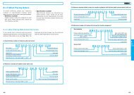
K1 Lubrication Unit<br />
Identification Number<br />
Refer to the following numbering system when ordering.<br />
Note: For more bearing seal options<br />
see page 4.<br />
Interchangeable Ball Slide<br />
Series Code<br />
Size Number<br />
Example:<br />
Interchangeable Standard Ball slide length Thickness Thickness of Grease fitting<br />
Ball Slide Ball slide Ball Slide with two <strong>NSK</strong> K1 of <strong>NSK</strong> K1 protective cover projection<br />
size code form length L V1 V2 N (mm)<br />
AN EM 55 65.6<br />
LAH15 GM 74 84.6<br />
AN EM 69.8 80.4<br />
LAH20 BN GM 91.8 102.4<br />
AN/AL EM 79 90.6<br />
LAH25 BN/BL GM 107 118.6<br />
4.5 0.8 5<br />
4.5 0.8 14<br />
5.0 0.8 14<br />
AN/AL 85.6 97.6<br />
LAH30 EM 98.6 110.6 5.0 1.0 14<br />
BN/BL GM 124.6 136.6<br />
LAH35<br />
LAH45<br />
LAH55<br />
LAH65**<br />
LAS15<br />
LAS20<br />
LAS25<br />
LAS30<br />
LAS35<br />
L A H 30 AN Z - K1<br />
Interchangeable <strong>Linear</strong> Guide Dimensions – LH, LS, LW, LU, LE Series Unit: mm<br />
AN/AL EM 109 122<br />
BN/BL GM 143 156<br />
AN EM 139 154<br />
BN GM 171 186<br />
AN EM 163 178<br />
BN GM 201 216<br />
AN EM 193 211<br />
BN GM 253 271<br />
AL<br />
EL<br />
FL 56.8 66.4<br />
CL KL 40.4 50<br />
AL<br />
EL<br />
FL 65.2 75.8<br />
CL KL 47.2 57.8<br />
AL<br />
EL<br />
FL 81.4 92<br />
CL KL 59.4 70<br />
AL<br />
EL<br />
FL 96.4 108.4<br />
CL KL 67.4 79.4<br />
AL<br />
EL<br />
FL 108 121<br />
CL KL 77 90<br />
5.5 1.0 14<br />
6.5 1.0 15<br />
6.5 1.0 15<br />
8.0 1.0 16<br />
4.0 0.8 5<br />
4.5 0.8 14<br />
4.5 0.8 14<br />
5.0 1.0 14<br />
5.5 1.0 14<br />
LAW17 EL 51.4 61.6 4.5 0.6 5<br />
LAW21 EL 58.8 71.4 5.5 0.8 13<br />
LAW27 EL 74 86.6 5.5 0.8 13<br />
LAW35 EL 108 123 6.5 1.0 13<br />
LAW50 EL 140.6 155.6 6.5 1.0 14<br />
LAU09 AR TR 30 36.4 2.7 0.5 –<br />
LAU12 AR TR 35.2 42.2 3.0 0.5 –<br />
LAU15 AL 43.6 51.8 3.5 0.6 –<br />
LAE09 AR TR 39.8 46.8 3.0 0.5 –<br />
LAE12 AR 45 53 3.5 0.5 –<br />
LAE15 AR 56.6 66.2 4.0 0.8 –<br />
* For Protector and Double Seal Information for LH Series please see page 13.<br />
* For Protector and Double Seal Information for LS Series please see page 21.<br />
<strong>NSK</strong> K1 Equipped<br />
Preload Code<br />
(Z: in case of a light preload)<br />
Ball Slide Shape Code<br />
33
K1 Lubrication Unit Handling<br />
and Assembly Instructions<br />
34<br />
<strong>NSK</strong> K1 <br />
Lubrication Unit<br />
Assembly Instructions for the K1 Lubrication Unit for <strong>Linear</strong> <strong>Guides</strong><br />
1. Slide linear bearing on to the linear rail, using the plastic provisional rail supplied.<br />
2. Remove the grease fitting from the end of the bearing.<br />
3. Remove the Phillips screws (2 pieces).<br />
4. Remove the end seal from end of bearing.<br />
5. Install threaded plug from K1 Lubrication Unit kit (or see option 9 and 10 depending on application).<br />
6. Install the cover plate from the K1 Lubrication Unit kit, to the end of bearing, against the end cap.<br />
7. Install K1 Lubrication Unit without fixing rings, so it can be expanded over the rail.<br />
8. Put the three (3) fixing rings in position on the K1 Lubrication Unit.<br />
9. Replace the end seal, in front of the K1 Lubrication Unit.<br />
10. Install connector screw for grease fitting.<br />
11. Replace the grease fitting in connector screw.<br />
Handling Instructions<br />
To maintain the <strong>NSK</strong> K1 Lubrication Unit Seal’s high<br />
efficiency over a long period of time, please follow<br />
these instructions.<br />
1. Permissible temperature range<br />
Max. operating temperature: 50°C (122°F)<br />
Max. peak temperature: 80°C (176°F)<br />
If not installed immediately, they should<br />
be kept refrigerated.<br />
Avoid storage in direct sunlight.<br />
2. Never leave the linear guide in close proximity to<br />
grease-removing organic solvents such as hexane,<br />
thinners, etc.<br />
Never immerse the linear guide in kerosene<br />
or rust preventative oils which contain kerosene.<br />
Note<br />
Other oils such as: water-based cutting oil, oil-based<br />
cutting oil, grease (mineral oil-AS2, ester-PS2) present<br />
no problems to the K1 Lubrication Units performance.<br />
12. Install the extension Phillips screws (2 pieces, supplied with the K1 Lubrication Unit seal kit).<br />
Note* The K1 Lubrication Unit has a shelf life. They should be installed immediately upon receipt. It is important to avoid direct sunlight and extreme heat conditions.
Unit Conversions<br />
To Convert<br />
From To Multiply By<br />
daN N 10.000<br />
kgf N 9.81<br />
kgf lbf 2.205<br />
kgf.cm lbf.in 0.868<br />
kgf.cm ozf.in 13.890<br />
kgf.m lbf.ft 7.234<br />
kgf.m lbf.in 86.811<br />
For more info<br />
www.npa.nsk.com<br />
N.m lbf.ft 0.738<br />
mm inch 0.03937<br />
inch mm 25.4<br />
35
Worldwide Sales Offices<br />
<strong>NSK</strong> Ltd.-Headquarters, Tokyo, Japan www.nsk.com<br />
<strong>Americas</strong> & Europe Department tel: 03-3779-7120<br />
Asia Marketing & Sales Department tel: 03-3779-7121<br />
Africa<br />
South Africa:<br />
<strong>NSK</strong> South Africa (Pty) Ltd.<br />
Johannesburg tel: (011) 458 3600<br />
Asia and Oceania<br />
Australia: www.nskaustralia.com.au<br />
<strong>NSK</strong> Australia Pty. Ltd.<br />
Melbourne tel: (03) 9764-8302<br />
China:<br />
<strong>NSK</strong> Hong Kong Ltd.<br />
Hong Kong tel: 2739-9933<br />
Kunshan <strong>NSK</strong> Co., Ltd.<br />
Kunshan tel: 0520-7305654<br />
Guizhou HS <strong>NSK</strong> Bearings Co., Ltd.<br />
Anshun tel: 0853-3521505<br />
<strong>NSK</strong> (Shanghai) Trading Co., Ltd.<br />
Shanghai tel: 021-62099051<br />
<strong>NSK</strong> representative office<br />
Beijing tel: 010-6590-8161<br />
<strong>NSK</strong> representative office<br />
Shanghai tel: 21-6209-9051<br />
<strong>NSK</strong> representative office<br />
Guangzhou tel: 020-8732-0583<br />
<strong>NSK</strong> representative office<br />
Anshun tel: 0853-3522522<br />
India:<br />
Rane NASTECH Ltd.<br />
Chennai tel: 04114-65313, 65314, 65365, 66002<br />
<strong>NSK</strong> representative office<br />
Chennai tel: 044-4334732<br />
Indonesia:<br />
P.T. <strong>NSK</strong> Bearings Manufacturing Indonesia<br />
Jakarta tel: 021-898-0155<br />
Korea:<br />
<strong>NSK</strong> Korea Co., Ltd.<br />
Seoul tel: 02-3287-0300<br />
<strong>NSK</strong> Korea Co., Ltd., Changwon Plant<br />
Changwon tel: 0551-287-6001<br />
Malaysia:<br />
<strong>NSK</strong> Bearings (Malaysia) Sdn. Bhd.<br />
Kuala Lumpur tel: 03-7958-4396<br />
<strong>NSK</strong> Micro Precision (M) Sdn. Bhd.<br />
Kuala Lumpur tel: 03-961-6288<br />
New Zealand: www.nsk-rhp.co.nz<br />
<strong>NSK</strong> New Zealand Ltd.<br />
Auckland tel: (09) 276-4992<br />
Philippines:<br />
<strong>NSK</strong> representative office<br />
Manila tel: 02-759-6246<br />
Singapore:<br />
<strong>NSK</strong> International (Singapore) Pte Ltd.<br />
Singapore tel: (65) 273 0357<br />
<strong>NSK</strong> Singapore (Pte) Ltd.<br />
Singapore tel: (65) 278 1711<br />
Taiwan:<br />
Taiwan <strong>NSK</strong> Precision Co., Ltd.<br />
Taipei tel: 02-2591-0656<br />
Thailand:<br />
<strong>NSK</strong> Bearings (Thailand) Co., Ltd.<br />
Bangkok tel: 02-6412150~58<br />
<strong>NSK</strong> Safety Technology (Thailand) Co., Ltd.<br />
Chonburi tel: (038) 214-317-8<br />
Siam NASTECH Co., Ltd.<br />
Chachoengsao tel: (038) 522-343~350<br />
Europe<br />
<strong>NSK</strong> Europe Ltd.<br />
(European Headquarters) www.eu.nsk.com<br />
Maidenhead, England tel: 0162-850-9800<br />
France:<br />
<strong>NSK</strong> France S.A.<br />
Paris tel: 01 30 57 39 39<br />
Germany:<br />
<strong>NSK</strong> Deutschland Gmbh<br />
Düsseldorf tel: 02102-481-0<br />
<strong>NSK</strong> Steering Systems Europe Ltd.<br />
Stuttgart tel: 0771-79082-277<br />
Neuweg Fertigung Gmbh<br />
Munderkingen tel: 07393-540<br />
Italy:<br />
<strong>NSK</strong> Italia S.P.A.<br />
Milano tel: 02-995-191<br />
Poland:<br />
<strong>NSK</strong> Europe Ltd. Warsaw Liaison Office<br />
Warsaw tel: 48-22-645-1525, 1526<br />
<strong>NSK</strong> Iskra S.A.<br />
Kielce tel: 48-41-366-6111<br />
Spain:<br />
<strong>NSK</strong> Spain S.A.<br />
Barcelona tel: 93-575-4041<br />
Turkey:<br />
<strong>NSK</strong> Bearings Middle East Trading Co., Ltd.<br />
Istanbul tel: 90-216-442-7106<br />
United Kingdom:<br />
<strong>NSK</strong> Bearings Europe Ltd.<br />
Peterlee, England tel: 0191-586-6111<br />
<strong>NSK</strong> UK Ltd.<br />
Newark, England tel: 0163-660-5123<br />
<strong>NSK</strong> Steering Systems Europe Ltd.<br />
Coventry, England tel: 024-76-588588<br />
North and South America<br />
<strong>NSK</strong> <strong>Americas</strong>, Inc. (American Headquarters)<br />
Ann Arbor, Michigan, U.S.A. tel: 734-913-7500<br />
Argentina:<br />
<strong>NSK</strong> Argentina SRL<br />
Buenos Aires tel: 011-4762-6556<br />
Brazil: www.br.nsk.com<br />
<strong>NSK</strong> Brasil Ltda.<br />
São Paulo tel: 011-3269-4700<br />
Canada: www.ca.nsk.com<br />
<strong>NSK</strong> Canada Inc.<br />
Toronto tel: 905-890-0740<br />
Mexico:<br />
<strong>NSK</strong> Rodamientos Mexicana, S.A. de C.V.<br />
Mexico City tel: 5-301-2741<br />
United States of America: www.us.nsk.com<br />
<strong>NSK</strong> Corporation<br />
Ann Arbor, Michigan tel: 734-913-7500<br />
Sales Offices:<br />
Ann Arbor, Michigan tel: 734-913-7500<br />
Santa Fe Springs, California tel: 562-968-1000<br />
<strong>NSK</strong> American Technical Center<br />
Ann Arbor, Michigan tel: 734-913-7500<br />
<strong>NSK</strong> Precision America, Inc.<br />
Franklin, Indiana tel: 317-738-5038<br />
San Jose, California tel: 408-944-9400<br />
www.npa.nsk.com<br />
NKS Steering Systems America<br />
Bennington, Vermont tel: 802-442-5448<br />
<strong>NSK</strong> Latin America Inc. www.la.nsk.com<br />
Miami, Florida tel: (305) 477-0605<br />
<strong>NSK</strong> Ltd. has a basic policy not to export any products or technology designated as controlled items by export-related laws. When exporting the products in this brochure, the<br />
laws of the exporting country must be observed. Specifications are subject to change without notice and without any obligation on the part of the manufacturer. Every care has<br />
been taken to ensure the accuracy of the data contained in this brochure, but no liability can be accepted for any loss or damage suffered through errors or omissions. We will<br />
gratefully acknowledge any additions or corrections.<br />
CAT. No.LG0599C 2007 Printed in Canada ©<strong>NSK</strong> 2007. The contents of this publication are the copyright of the publishers.