CPT International 02/2016
The leading technical journal for the global foundry industry – Das führende Fachmagazin für die weltweite Gießerei-Industrie
The leading technical journal for the
global foundry industry – Das führende Fachmagazin für die
weltweite Gießerei-Industrie

Create successful ePaper yourself
Turn your PDF publications into a flip-book with our unique Google optimized e-Paper software.
www.giesserei-verlag.de<br />
June<br />
<strong>2016</strong><br />
CASTING<br />
PLANT AND TECHNOLOGY<br />
INTERNATIONAL<br />
2<br />
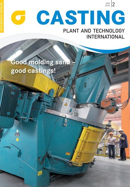
Good molding sand –<br />
good castings!
Bühler Services<br />
Modular, individual, flexible. Economical production requires optimum<br />
productivity, quality, and uptime. A stable manufacturing process and swift<br />
recovery from production interruptions are essential ingredients of your<br />
success. Bühler offers services so you can maintain your competitive edge.<br />
Whether you need spare parts, machine inspections, or a customized service<br />
package, Bühler has the right solution for you.<br />
Bühler AG, Die Casting, CH-9240 Uzwil, Switzerland<br />
T +41 71 955 12 12, F +41 71 955 25 88<br />
die-casting@buhlergroup.com, www.buhlergroup.com/die-casting<br />
Innovations for a better world.
EDITORIAL K<br />
Germany’s foundry sector<br />
– a family-oriented branch<br />
of industry!<br />
Albert Handtmann’s foundry in Biberach in southern Germany is the country’s<br />
largest family-owned light-metal foundry. In addition to Biberach, Handtmann<br />
Holding operates other foundries in Annaberg in Saxony, Košice in<br />
Slovakia, and Tianjin in China. This family-run global player – characterized<br />
by hard work, productivity, innovations, and, as in this case, expansions – is<br />
our figurehead for the German foundry industry in this issue. The company is<br />
embodied by the 88- year-old Albert Handtmann, who took over management<br />
in 1945 but has now passed it on to his son. Read our company portrait<br />
from P. 36.<br />
Innovations in material development and plant technology make up a large<br />
proportion of our summer issue. For material development we turn our attention<br />
to trimal-37, an alloy of aluminum, silicon and manganese, from which<br />
cast nodes that are weight-optimized but nevertheless extremely stable are<br />
produced for vehicle bodies. We present other interesting examples of applications<br />
for the material in our article from P. 8.<br />
Our author Herbert Smetan describes a sophisticated casting system: dynamic<br />
tilt casting on low-pressure casting machines. It is used for casting highly<br />
stressed cylinder heads. The casting system enables turbulence-free mold filling<br />
with absolutely clean and oxide-free metal. Read more from P. 23.<br />
The appearance of CASTING in late June <strong>2016</strong> signals the opening of the international<br />
Automatica trade fair in Munich (21 - 24 June). In addition to Industry<br />
4.0 (the trendy topic of our time), involving the intermeshing of industrial<br />
production with state-of-the-art information and communication<br />
technology, the fair will also focus on robotics and other industrial automation<br />
solutions. European foundries do not lag behind here: KUKA robots clean casting<br />
molds at the BMW light-metal foundry in Landshut. They are ‘taught’ their<br />
tasks by foundry employees (from P. 34). Magma 5 simulation software permits<br />
the stable casting of oversized frame components at the Swiss foundry DGS<br />
Druckguss (from P. 28).<br />
Have a good read!<br />
Robert Piterek, e-mail: robert.piterek@bdguss.de<br />
Casting Plant & Technology 2/<strong>2016</strong> 3
K FEATURES<br />
INTERVIEW<br />
with Till Schreiter<br />
“Demand is shifting towards high-performance applications” 6<br />
MATERIALS<br />
Kleine, Andreas; Böhmer, Franz-Heinrich; Hoffmann, Ellen; Koch, Hubert<br />
Alloy trimal-37 in modern car body applications 8<br />
Vollrath, Klaus<br />
Mercedes C-Class: the great stride to aluminium casting 12<br />
MELTING SHOP<br />
Trauzeddel, Dietmar<br />
Pouring furnaces and pouring devices – state of the art and development<br />
targets 16<br />
CASTING TECHNOLOGY<br />
Smetan, Herbert<br />
Dynamic tilt casting with low-pressure die casting machines 23<br />
Cover-Photo:<br />
Maschinenfabrik Gustav Eirich GmbH & Co KG<br />
Walldürner Str. 50<br />
74736 Hardheim<br />
Tel: + 49 6283 510<br />
Fax: + 49 6283 51 325<br />
eirich@eirich.de<br />
www.eirich.com<br />
CLEANING, FETTLING & FINISHING<br />
Malashonak, Vadim<br />
Increasing blasting efficiency through innovative blasting media 26<br />
SIMULATION<br />
Schmidt, Axel<br />
DGS produces one of the largest die cast parts worldwide 28<br />
Read our News on Eirich on page 41<br />
16 28<br />
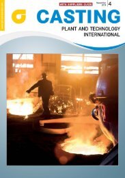
Casting furnaces and devices for cast iron are an integral<br />
part of the molding lines. Since its development inductive ly<br />
heated furnaces with compressed air emptying found a firm<br />
place in foundries (Photo: Dietmar Trauzeddel)<br />
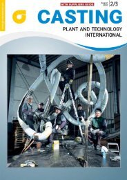
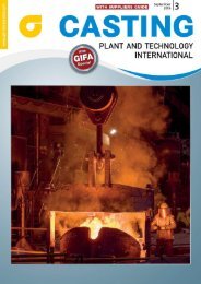
DGS Druckguss produces frames for hot water solar panels.<br />
The production was changed from welded extrusion molded<br />
parts to aluminium die castings. The castings are amongst<br />
the largest die cast parts worldwide (Photo: DGS Druckguss)
CASTING<br />
2 | <strong>2016</strong><br />
PLANT AND TECHNOLOGY<br />
INTERNATIONAL<br />
Nowaczyk, Christof<br />
Core shooting simulation – to the economic and environmental advantage of the<br />
foundry 30<br />
AUTOMATION<br />
Schwarzbach, Laura<br />
Well guided 34<br />
COMPANY<br />
Hardke, Karin<br />
The Handtmann Group – a family company with a future 36<br />
K COLUMNS<br />
Editorial 3<br />
News in brief 40<br />
Brochures 44<br />
Fairs and congresses / Advertisers´ index 46<br />
Preview of the next issue/Imprint 47<br />
36<br />
Albert Handtmann Metallgusswerk in Biberach is Germany’s largest family-owned light-metal foundry. Arthur Handtmann took over his<br />
parent’s small foundry in 1945, in the following decades the company developed into an efficient, innovative and value-oriented global player<br />
with production sites in China, Slowakia and Germany. Today the 88-year old entrepreneur has no time for retirement – there is too much to<br />
be done (Photo: Klaus Bolz)
K INTERVIEW<br />
“Demand is shifting towards<br />
high-performance applications”<br />
Interview with Till Schreiter, Managing Director of the ABP Induction Systems GmbH in<br />
Dortmund, Germany, since April 2015<br />
Till Schreiter is the new Managing Director of ABP Induction Systems. The company considers itself a supplier of sustainable<br />
induction systems with short payback times and many customer advantages (Photos: ABP)<br />
ABP Induction Systems in Dortmund<br />
has celebrated its 10-year jubilee last<br />
November. As the new Managing Director,<br />
how do you see the history of<br />
your still-young company?<br />
ABP emerged from the process automation<br />
division of Asea Brown Boveri<br />
(ABB), which already had a more than<br />
one-hundred-year tradition of constructing<br />
induction plants. With this<br />
historical record behind us, we have<br />
written our own short history and<br />
made ABP into a company with its<br />
own distinctive profile. We are now<br />
one of the leading suppliers for inductive<br />
melting and heating. And our customers<br />
from the foundry, forging and<br />
steel industries are often world market<br />
leaders themselves. As a result of use<br />
in the automotive supply industry, in<br />
particular, ABP furnaces have been involved<br />
in the production of millions<br />
of parts with high value creation. The<br />
Dortmund site is also growing – and is<br />
a dependable employer and taxpayer.<br />
ABP’s business is going well. You currently<br />
sell numerous melting furnaces<br />
worldwide, including in China and<br />
India. Which furnaces are particularly<br />
popular and why?<br />
Most of our business is with furnaces<br />
with a capacity of 2 - 35 t. Whereby<br />
we are increasingly observing that<br />
demand is shifting towards high-performance<br />
applications. So, for example,<br />
we commissioned a 30-t furnace<br />
with an induction power of 24 MW at<br />
a major customer of ours, and we actually<br />
followed this up with a furnace<br />
with a melting capacity of 65 t and induction<br />
power of 42 MW. These fur-<br />
6 Casting Plant & Technology 2/<strong>2016</strong>
naces are particularly popular because<br />
production and batch quantities, particularly<br />
for the automotive industry,<br />
are constantly growing. In the field of<br />
forming technology, we were able to<br />
convince the largest Chinese automotive<br />
supplier of the quality of a heating<br />
plant with intelligent heat recovery –<br />
installation has taken place in spring<br />
<strong>2016</strong>.<br />
Induction furnace production at ABP in Dortmund<br />
In April 2015 you replaced Dr. Wolfgang<br />
Andree, who had been Managing<br />
Director for many years. What is<br />
your strategy for the future?<br />
ABP considers itself a supplier of sustainable<br />
induction systems with short<br />
payback times and many customer<br />
advantages. We believe that the quality<br />
of our employees is an important<br />
feature that differentiates us from the<br />
competition. As a result of continuous<br />
growth in recent years, we have been<br />
able to build up special problem-solving<br />
competence with a mix of experienced<br />
and young personnel. Perhaps<br />
this is why we are able to test new technologies<br />
or adapt to our customers’ requirements<br />
particularly rapidly. A sustainable<br />
product management system<br />
means, for example, that we have a<br />
dense network of local service workshops<br />
for the important after-market<br />
business. And we want to be even more<br />
flexible in future regarding production<br />
conditions.<br />
www.abpinduction.com<br />
CastTec <strong>2016</strong><br />
The world of cast iron materials – Diversity for the future“<br />
3rd <strong>International</strong> Conference · Maritim Konferenzhotel Darmstadt, Darmstadt, Germany<br />
November 24 – 25, <strong>2016</strong><br />
Information and Registration on www.casttec<strong>2016</strong>.com or at atm Gesellschaft für aktives technisches Marketing GmbH,<br />
phone: +49/ 40/ 228 13 77 90, E-Mail: contact@casttec<strong>2016</strong>.com<br />
CastTec <strong>2016</strong> – The overall industry gathering<br />
In power generation, engineering or transportation – cast iron components are omnipresent!<br />
Near-net-shape, energy-efficient and economical by the use of innovative solutions in design and material.<br />
As the third in it’s series CastTec <strong>2016</strong> cordially invites users, design engineers and foundry experts<br />
to the industry gathering around the topic cast iron!<br />
Exciting lectures, a modern exhibition, the optional visitation at the Fraunhofer Institute for<br />
Structural Durability and System Reliability LBF as well as an attractive evening event will<br />
give an extensive overview of recent developments and trends from science and industry and<br />
will offer you an intensive exchange with colleagues in the field.<br />
Experience the wide world of cast iron materials and its applications!<br />
Information and registration on<br />
www.casttec<strong>2016</strong>.com
K MATERIALS<br />
Machining of a die casting at the Trimet die casting foundry in Harzgerode (Photos and Graphics: Trimet)<br />
Authors: Andreas Kleine, Franz-Heinrich Böhmer, Ellen Hoffmann, Trimet Aluminium SE, Harzgerode, and Hubert<br />
Koch, Trimet Aluminium SE, Essen<br />
Alloy trimal-37 in modern car body<br />
applications<br />
Pressure die cast hubs made of the aluminium alloy trimal-37 are used in car body construction<br />
to achieve a weight-optimized self-supporting framework structure<br />
Introduction<br />
In the past, various trends, such as<br />
growing safety requirements, higher<br />
powered engines and the demand for<br />
increased comfort, have led to a constant<br />
increase in vehicle weight. In<br />
order to be able to meet future CO 2<br />
emission targets, it is indispensible to<br />
markedly reduce the weight of cars.<br />
In this context, car body construction<br />
plays a key role, last but not least<br />
due to the growing share of the lightweight<br />
construction material aluminium.<br />
This article focuses on what is generally<br />
referred to as cast hubs, namely<br />
multifunctional pressure die castings<br />
of complex geometries, which in<br />
combination with extruded profiles<br />
and metal panels make a car body a<br />
self-supporting structure.<br />
The alloy trimal-37<br />
The trimal-37 alloy (AlSi9Mn) has outstanding<br />
casting properties. Its iron<br />
content of < 0.15 % inhibits the formation<br />
of coarse intermetallic phases.<br />
This makes trimal-37 highly ductile<br />
even in the as-cast state. The ductility<br />
is further enhanced by modifying the<br />
alloy with strontium, which results in<br />
a fine eutectic silicon phase. Ductility<br />
8 Casting Plant & Technology 2/<strong>2016</strong>
Alloy State R p0.2<br />
in MPa R m<br />
in MPa A in % Hardness inHB<br />
F 120 - 140 250 - 290 8 - 15 80 - 90<br />
trimal-37<br />
O 100 - 120 200 - 240 10 - 18 65 - 75<br />
Table 1: Static mechanical properties of the alloy trimal-37. F = as-cast; O = soft-annealed<br />
can be increased even further by a TO<br />
heat treatment. The manganese content<br />
in the alloy prevents adhesion to<br />
the mold. This ensures that especially<br />
highly complex structural castings<br />
with extensive surface areas can be<br />
easily removed from the mold. The elements<br />
zircon and vanadium provide<br />
the necessary strength at room temperature<br />
and ensure that the requirements<br />
in terms of short-time as well<br />
as long-time thermal stability are securely<br />
met. The mechanical properties<br />
of trimal-37 are summarized in<br />
Table 1 [1].<br />
Examples of application of<br />
trimal-37<br />
Hinge mounting element for the<br />
AUDI Q7<br />
The hinge mounting element is a corner<br />
element in the rear end roof structure<br />
of the AUDI Q7. Actually, it forms<br />
the vertex of three coordinates: the<br />
longitudinal roof beam, the transverse<br />
roof beam and the side beam. It<br />
has been designed to also accommodate<br />
the hinge of the rear hatch.<br />
The die cast hinge mounting element<br />
(Figure 1) features excellent stiffness<br />
due to the design of the ribbed<br />
structure tailored to the load acting on<br />
the part and the high yield strength of<br />
trimal-37. As the casting is used in its<br />
as-cast state, the part is also free from<br />
distortions, ensuring that the exacting<br />
geometric tolerance specifications are<br />
met. The innovative multi-material design<br />
of the AUDI Q7 calls for the use of<br />
self-pierce riveting systems to join materials<br />
as diverse as steel and aluminium<br />
panels and extruded aluminium<br />
profiles with the casting.<br />
As shown in Figure 2, the riveting<br />
joint is set by positioning the top material<br />
layer (aluminium sheet) and the<br />
bottom layer (trimal-37, wall thickness<br />
approx. 2.5 mm) between the<br />
downholder and a die. A stamp inside<br />
the downholder then presses the<br />
a<br />
Figure 1: a) Front and b) back view of the die casting: Hinge mounting unit<br />
for the Audi Q7 (CAD image); dimensions: 630 x 530 x 70 mm; weight: 3.4 kg<br />
Figure 2: Process steps of self-pierce riveting (courtesy: Böllhoff) [3]<br />
Figure 3: Cross-section of joint made with a self-pierce rivet<br />
b<br />
Casting Plant & Technology 2/<strong>2016</strong> 9
K MATERIALS<br />
a<br />
Figure 4: a) Front and b) back view of the die cast heel board for the AUDI<br />
A8 (CAD image); dimensions: 440 x 210 x 240 mm; weight: 2.1 kg<br />
a<br />
Figure 5: Micrograph of a welded joint: a) microsection, b) image analysis;<br />
porosity: 3.6%<br />
b<br />
b<br />
self-piercing semi-tubular rivet into<br />
the double-layer material. The rivet<br />
penetrates through the aluminium<br />
sheet and is spread in the lower material<br />
made of trimal-37 under the influence<br />
of the die [2, 3]. Due to the high<br />
ductility and excellent forming properties<br />
of trimal-37, there is no risk of<br />
cracks forming in the lower material<br />
due to the spreading of the rivet. As<br />
the lower material made of trimal-37 is<br />
not pierced, the resulting joint is localized<br />
and impervious to gas and liquid.<br />
This form-closed joint is very strong.<br />
Figure 3 illustrates the suitability of trimal-37<br />
to be joined with another material<br />
by self-pierce riveting.<br />
Heel board for the AUDI A8<br />
The heel board (Figure 4) is a key component<br />
in the rear floor structure of the<br />
AUDI A8. It connects, for example, the<br />
transmission hump with the floor panels.<br />
Besides mechanical joining by selfpierce<br />
rivets or flow-drill screws, thermal<br />
joining by MIG welding (metal<br />
inert-gas welding) plays an important<br />
role in this application. In combination<br />
with a process-compatible<br />
mold design, optimized coating of the<br />
mold with release agents developed for<br />
Figure 6: Cross member of the battery pan in the Porsche 991 II (CAD image); dimensions: 830 x 130 x 70 mm; weight:<br />
1.2 kg<br />
10 Casting Plant & Technology 2/<strong>2016</strong>
this particular application and a vacuum-supported<br />
casting process, trimal-37<br />
provides superior weldability.<br />
Figure 5 shows an example of a MIG<br />
welded joint between a die casting<br />
made of trimal-37 and an aluminium<br />
panel using AlSi12 wire as filler metal.<br />
The welded joint was made as part of<br />
an accompanying test of a series production<br />
run. As the image analysis<br />
shows, the welded joint features 3.6 %<br />
porosity. Thus it easily achieves the<br />
specified maximum porosity of 10 %.<br />
Cross member for battery pan<br />
in the Porsche 991 II<br />
The cross member shown in Figure 6<br />
has the function to securely fix the battery<br />
within the engine compartment<br />
of the car body. For this purpose, the<br />
ends of the cross member are screwed<br />
to mounting brackets.<br />
The cross member must feature a<br />
specified flexural rigidity under defined<br />
conditions of use. This is ensured<br />
by the specific cross member design allowing<br />
the part to cope with the typical<br />
stresses of the application and by the<br />
good strength properties of trimal-37.<br />
Summary<br />
The described examples of application<br />
demonstrate the versatility of trimal-37<br />
in modern car body construction. The<br />
material’s suitability for self-pierce riveting<br />
as well as its good weldability and<br />
formability are basic conditions for the<br />
application of all joining methods relevant<br />
in this area.<br />
By maintaining material development<br />
and testing activities at different<br />
locations and by interdisciplinary<br />
collaboration and the use of most advanced<br />
development and testing techniques,<br />
Trimet is capable of providing<br />
– in a timely manner – practice-oriented<br />
solutions as the basis for innovative<br />
product development.<br />
Trimet covers all essential phases of<br />
component development, from the<br />
conceptual phase via the design phase<br />
using all relevant CAD systems, including<br />
numerical simulations of the<br />
pouring and solidification processes,<br />
through to prototype casting and investigations<br />
concerning the behaviour<br />
of a component. Trimet’s in-house tool<br />
making facilities and the other process<br />
steps performed in-house, including<br />
heat treatment, machining, surface<br />
treatment, completion and assembly<br />
form the basis for a rapid implementation<br />
of the product idea into a product<br />
ready for installation.<br />
References:<br />
www.trimet.com<br />
Setting The Standards For Highest<br />
Efficiency In Thermal Processing<br />
JASPER<br />
PulsReg® Zentral Regenerator, 12 MW<br />
Gesellschaft für Energiewirtschaft und Kybernetik mbH / Bönninghauser Str. 10 / D-59590 Geseke<br />
Telefon: +49 2942 9747 0 / Fax: +49 2942 9747 47 / www.jasper-gmbh.de / info@jasper-gmbh.de<br />
Casting Plant & Technology 2/<strong>2016</strong> 11
K MATERIALS<br />
Author: Klaus Vollrath, Aarwangen, Switzerland<br />
Mercedes C-Class: the great stride<br />
to aluminum casting<br />
Hybrid bodies with mass-produced aluminum structural castings<br />
Mercedes Benz; C-Class T-Model (Photo: Daimler AG)<br />
The body of the new C-Class is the first<br />
for Mercedes, which has completed the<br />
step from the former steel structure to<br />
a composite construction (Figure 1)<br />
for large-scale serial production. The<br />
combination of high-strength steels<br />
and aluminum makes it possible to design<br />
the car considerably lighter, while<br />
improving comfort, driving characteristics<br />
and passenger protection. Such a<br />
conversion of production technology<br />
is a truly Herculean task with numerous<br />
risks when undertaken on a large<br />
scale – four sites manufacturing up to<br />
2,000 vehicles every day. The challenges<br />
for the specialists – charged with the<br />
task of making the appropriate technology<br />
so controllable that a smooth<br />
worldwide supply of the necessary<br />
parts could be guaranteed – were correspondingly<br />
large.<br />
“As a result of the transition to an<br />
innovative aluminum hybrid design<br />
Daimler, in Stuttgart, Germany, has<br />
been able to save about 70 kg in the<br />
body-in-white of the new C-Class,”<br />
says Axel Schmidt (Figure 2), Manager<br />
of Technology, Development and<br />
Project Management at DGS Druckguss<br />
Systeme in St. Gallen, Switzerland. This<br />
represents a weight saving of about 20-<br />
25 % of the total weight of the bodyin-white,<br />
depending on the vehicle<br />
variant – an important contribution towards<br />
reducing fuel consumption and<br />
the emission of CO 2<br />
. The fuel consumption<br />
of the Bluetec C180 and C200 basis<br />
versions is only 3.8 l diesel/100 km with<br />
emissions of 99 g CO 2<br />
/100 km. In order<br />
to achieve this success, the engineers<br />
had to completely redesign the bodyin-white<br />
while extensively exploiting<br />
aluminum castings, hot-formed steel<br />
components, and ultra-high-strength<br />
steels. Moreover, all the body parts visible<br />
externally are also made of aluminum.<br />
Ultimately, vehicle weight has<br />
been reduced by about 100 kg.<br />
12 Casting Plant & Technology 2/<strong>2016</strong>
The advantages of extensive<br />
aluminum structural castings<br />
“The new body contains a total of<br />
seven large-scale aluminum castings,”<br />
adds Axel Schmidt. These seven components<br />
together only weigh 19.2 kg.<br />
Castings were used because these parts<br />
had to have a very complex geometry<br />
with numerous reinforcements and<br />
wall thickness transitions. The suspension<br />
strut consoles of the predecessor<br />
model consisted of five steel parts,<br />
while a total of 13 parts were required<br />
for the rear-axle cross-members. The<br />
advantage of using aluminum castings<br />
in these areas lies not only in the considerably<br />
lower specific weight compared<br />
to steel, but above all in the significantly<br />
greater degree of freedom for<br />
the designers, who can create even very<br />
complicated geometries with load-oriented<br />
wall thickness transitions and<br />
deep rib structures or projections –<br />
without having to worry about restrictions<br />
or additional joining processes.<br />
The advantages are considerable, not<br />
only regarding weight, the number<br />
of individual parts, and the necessary<br />
joining operations, but also in view of<br />
reduced quality-assurance costs.<br />
The transition to worldwide<br />
mass production<br />
“For us, the actual challenge in this<br />
project lay in jointly developing (together<br />
with Daimler and another<br />
partner) the process technology for<br />
large-series production on a worldwide<br />
scale,” explains Axel Schmidt.<br />
Daimler had systematically prepared itself<br />
for this conversion for many years<br />
(Figure 3). The initial steps were the<br />
fully aluminum bodies for the sports<br />
car models SLS AMG and SL in smallscale<br />
production. These were followed<br />
in 2013 by the introduction of hybrid<br />
bodies made of aluminum and steel in<br />
the S-Class, with daily volumes of up<br />
to 550 units – already corresponding<br />
to mid-scale serial production. The introduction<br />
of the new C-Class in 2014<br />
marked the final step towards largescale<br />
production of up to 2,000 units a<br />
day. Which made it mandatory to ensure<br />
that identical standards – regarding<br />
the design, the process technology<br />
in the vehicle production plant, the<br />
Figure 1: Aluminum structural castings in the body-in-white of the new C-Class:<br />
suspension strut consoles (1+2), rear side members (3+4), mountings for shock<br />
absorbers (5+6), and rear axle cross-member (7) (Graphics: Daimler AG)<br />
package of connecting parts, quality<br />
definitions, and the so-called MB standard<br />
– were maintained worldwide at<br />
all four production sites (Germany,<br />
the USA, South Africa and China) and<br />
by all six suppliers. The casting suppliers<br />
had to observe worldwide uniform<br />
specifications for tools, alloys, castings<br />
and heat-treatment parameters,<br />
as well as for inspection and straightening<br />
equipment.<br />
Top-quality technology development<br />
“The invitation to join this development<br />
team was the result of hard work,<br />
which earned us a reputation as a technology<br />
pioneer in the area of producing<br />
large structural castings made of<br />
aluminum and magnesium,” according<br />
to Axel Schmidt. The company<br />
had built up comprehensive mutual<br />
trust in development partnerships<br />
over many years. The team’s task was<br />
to create all the prerequisites for the<br />
timely start of production of the new<br />
C-Class with four start-of-production<br />
deadlines on four continents – within<br />
just seven months. This involved<br />
developing and optimizing the cost<br />
structures, production chains, and<br />
qualification concepts. It was necessary<br />
to define joint standards for processes,<br />
tools, specifications and quality<br />
Figure 2: “The absolute key to success<br />
ultimately remains the expertise to<br />
precisely master one’s own processes<br />
– and the subsequent optimization of<br />
the costs situation,” stresses Axel Schmidt<br />
(Photo: Johannes Müller)<br />
inspections in order to ensure comparable<br />
production processes and results.<br />
This meant going into details such as<br />
the extent of punching and machining<br />
processes, the positioning and clamping<br />
points for the mechanical processing,<br />
or the removal points for material<br />
samples. Further aspects involved the<br />
frames and the parameters for heat<br />
Casting Plant & Technology 2/<strong>2016</strong> 13
K MATERIALS<br />
treatment, the straightening concept<br />
(including a binding design for the<br />
alignment gauges), or a uniform packaging<br />
and dispatch concept.<br />
Other aspects were also required to<br />
ensure a smooth worldwide supply of<br />
all the production sites with the necessary<br />
structural castings. For example,<br />
it was indispensable to work out strategies<br />
and procedures for the qualification<br />
of new suppliers and sites that had<br />
no experience of such structural castings.<br />
The design and implementation<br />
of serial production in China presented<br />
perhaps the greatest challenge in<br />
this project due to differences in the<br />
level of mastery of the technologies<br />
and in local mentality, the time shift<br />
and, last but not least, the language<br />
problem. “We at DGS are particularly<br />
proud of being the first European<br />
die-caster to have accepted and successfully<br />
mastered this enormous challenge,”<br />
says a satisfied Axel Schmidt.<br />
Casting the rear side members<br />
“We produce four of the seven structural<br />
castings for the body: the two<br />
rear side members (Figure 4) and the<br />
two front suspension strut consoles,”<br />
says Axel Schmidt. At its St. Gallen<br />
works, DGS came up with a particularly<br />
innovative casting concept for<br />
the side members with dimensions<br />
of 480 x 315 x 290 mm, a component<br />
weight of 1.4 kg, and wall thicknesses<br />
of 2.0 - 3.0 mm. For the first time,<br />
such large structural castings were<br />
produced in a four-cavity mold on a<br />
Carat 320 die casting machine from<br />
Bühler, which is the largest installed<br />
casting cell in Switzerland, with a closing<br />
force of 3,200 t. After casting, the<br />
parts are cooled in water and individualized<br />
by stamping. Then they are immediately<br />
placed on the specially designed<br />
component holding fixtures<br />
of the heat-treatment racks in preparation<br />
for a two-step heat treatment.<br />
This gives the castings the specified<br />
mechanical characteristics: tensile<br />
strength R m<br />
≥180 MPa, yield strength<br />
R p 0.2<br />
≥ 120 MPa and elongation at break<br />
A5 ≥ 10 %. An additional criterion is a<br />
bending angle of at least 60 % to fracture<br />
determined on a flat sample. This<br />
criterion proves the suitability of the<br />
material for joining by means of punch<br />
riveting.<br />
Particularly high demands had to be<br />
met regarding the absence of defects in<br />
the castings. Casting takes place under<br />
high vacuum to ensure perfect microstructures.<br />
The melt is carefully refined<br />
before casting and flushed with inert<br />
gas in order to prevent gas and solid inclusions<br />
in the castings. Strict specifications<br />
apply for the selection and applications<br />
rules for mold release agents<br />
and plunger lubricants. Special requirements<br />
also apply for the microstructural<br />
and surface quality of the parts, particularly<br />
regarding the subsequent joining<br />
processes during body assembly.<br />
Production of the parts for installation<br />
in Germany and South Africa – up<br />
to 370,000 units a year – takes place at<br />
the DGS parent plant in St. Gallen in<br />
Switzerland, while the Chinese DGS<br />
subsidiary in Nansha produces up to<br />
130,000 units per year for China. The<br />
Mexican supplier Bocar – which entered<br />
into a close collaboration with<br />
DGS during the course of this project –<br />
is responsible for supplying the Daimler<br />
works in the USA.<br />
Manual straightening<br />
“One of the secrets of our success is the<br />
limitation of tension-related warping<br />
to a level that can be corrected by relatively<br />
simple adjustments,” reveals<br />
Schmidt. In practice, warpage is virtually<br />
unavoidable with such large<br />
and thin-walled components. This is<br />
mainly due to internal stresses resulting<br />
from the casting and stamping<br />
processes and further exacerbated by<br />
heat treatment. The trick is to master<br />
the process so skilfully as to minimize<br />
these deformations – this sorts the<br />
good casters from the rest. As the part<br />
Figure 3: The step-up to mass production requires the clarification and mastering of the most varied of details. This is<br />
why it has been systematically prepared via several models over many years (Graphics: Dr. Pfitzer, Daimler AG)<br />
14 Casting Plant & Technology 2/<strong>2016</strong>
Figure 4: The rear side members<br />
made of the alloy AlSi10MnMgSr<br />
have dimensions of 480 x 315 x<br />
290 mm and only weigh about<br />
1.4 kg each as a result of their low<br />
wall thicknesses of just 2 - 3 mm<br />
(Photo: Klaus Vollrath)<br />
shape for ensuring tight gap dimensions<br />
– also in order to limit the joining<br />
gap for adhesive seams – may only<br />
deviate by a maximum of ± 0.5 mm<br />
from the CAD dimensions, every casting<br />
must be inspected and, if necessary,<br />
straightened.<br />
DGS decided to make straightening<br />
a manual process in order to be<br />
able to profit from further process improvements,<br />
i.e. minimizing of deformations.<br />
An automated straightening<br />
process would require enormous investments<br />
and only be used for one specific<br />
component. Once installed, implementation<br />
of a subsequent optimization of<br />
straightening would no longer provide<br />
any major economic benefit.<br />
In the manual straightening process<br />
the part is examined on an electronic<br />
measurement system before<br />
the diverging locations are manually<br />
straightened by experienced specialists.<br />
Experience and a feeling for the<br />
parts are the most important prerequisites<br />
for a rapid and reliable straightening<br />
process. The straightening process<br />
is only completed when the measurement<br />
system provides an ‘in order’ result<br />
for all the specified positions.<br />
Fully automated further processing<br />
“The further processing steps take<br />
place with the help of robotized automated<br />
systems,” explains Schmidt.<br />
Grinding, which serves to prepare the<br />
parts for the subsequent joining processes<br />
in body construction, is particularly<br />
important. Grinding takes place<br />
in a fully encapsulated cell, in which<br />
several robots process the parts on different<br />
conveyor belts with a variety<br />
of grinding disks and brushes. The final<br />
station is a combined processing/<br />
assembly plant, in which the receiving<br />
threads for screwing onto the back<br />
axle are added and reinforced with a<br />
mounted stainless steel Helicoil. The<br />
thread is formed on a Milltap 700 CNC<br />
processing center from DMG with a<br />
special tool, and then the thread insert<br />
is fully automatically mounted in<br />
a specially developed assembly system.<br />
What distinguishes this station is its<br />
complete monitoring of the mounting<br />
process regarding the screw-in torque<br />
value, the position of the mounted Helicoils<br />
and, last but not least, removal<br />
of the Helicoil tang.<br />
Mastering the production<br />
process as the key to cost optimization<br />
“One of the decisive prerequisites for<br />
our success is the ability to reliably<br />
keep production processes under control<br />
within the tightest possible limits,”<br />
explains Axel Schmidt. The narrower<br />
the achievable property range can be<br />
kept, the closer one can approach the<br />
limit values demanded by customers<br />
regarding part properties. Many quality-determining<br />
process steps, such as<br />
heat treatment, are cost-intensive. It<br />
is, in effect, giving away money if, as<br />
a result of major process fluctuations,<br />
one achieves 20 % elongation at break<br />
instead of the required 10 %. There are<br />
also frequently further disadvantages,<br />
such as higher reject rates due to blister<br />
formation and stronger deformations<br />
because of this type of heat treatment.<br />
Customers, however, only pay for exactly<br />
what they asked for and specified.<br />
The same applies for agreed tolerances<br />
and inspections. In order to be<br />
able to act successfully here one must,<br />
of course, have as precise a knowledge<br />
as possible about the process chain and<br />
its main parameters and interactions<br />
such as, for example, the effect of the<br />
individual elements in the alloy. These<br />
interactions also apply regarding the<br />
question of to what extent which stages<br />
in the entire process chain can be automated.<br />
Of course, each automation<br />
process has the positive effect that one<br />
can better control and document the<br />
parameters of the particular sub-process.<br />
On the other hand, however, automation<br />
involves additional costs.<br />
Complete automation of the production<br />
process, therefore, does not necessarily<br />
create an optimal solution. “The<br />
absolute key to success ultimately remains<br />
the expertise to precisely master<br />
one’s own processes – and the subsequent<br />
optimization of the costs situation.<br />
Thanks to this capability, we are<br />
able to act successfully on fiercely competitive<br />
international markets despite<br />
high domestic wage levels,” stresses<br />
Axel Schmidt.<br />
www.dgs-druckguss.com<br />
Picture galery showing<br />
the manufacturing<br />
process at DGS<br />
Druckguss in St. Gallen,<br />
Switzerland<br />
http://bit.ly/22u6ndR<br />
Casting Plant & Technology 2/<strong>2016</strong> 15
K MELTING SHOP<br />
Overall view of an induction-heated pouring furnace (Photos and Graphics: Dietmar Trauzeddel)<br />
Author: Dietmar Trauzeddel, Simmerath-Lammersdorf<br />
Pouring furnaces and pouring<br />
devices – state of the art and<br />
development targets<br />
Part 1: Pouring furnaces<br />
Introduction<br />
The following article deals with pouring<br />
furnaces and pouring devices for<br />
cast iron that form an integral part of<br />
molding lines and are therefore essentially<br />
stationary, i.e., capable of only<br />
limited movement at the mold line.<br />
The need to develop and use automatic<br />
pouring furnaces or pouring devices<br />
for mold casting processes arose from<br />
a specific set of requirements. Thus, on<br />
the one hand, in manual pouring from<br />
a ladle the pouring parameters vary<br />
too much with the individual operator’s<br />
skills and daily form. As a result,<br />
the process is barely reproducible and<br />
the achievable weight precision is insufficient,<br />
amounting to approx. 5 %<br />
according to [1]. On the other hand,<br />
there are the production conditions resulting<br />
from an increasing automation<br />
of the molding process. On high-output<br />
molding machines of the type<br />
commonly used in high-volume production,<br />
the cycle time often amounts<br />
to as little as 6 – 15 s. Within this interval<br />
the system must manoeuver into<br />
the pouring position and fill the mold.<br />
Moreover, this needs to be achieved<br />
with a variable pouring rate corresponding<br />
to the mold’s intake capacity<br />
while ensuring a high repeatability<br />
and accuracy of the optimized pouring<br />
profile. The specific location of the<br />
mold’s sprue cup must be reached accurately<br />
within the available time win-<br />
16 Casting Plant & Technology 2/<strong>2016</strong>
dow. In addition, it is necessary to keep<br />
the pouring temperature and metal<br />
composition within close tolerances<br />
while also providing for a temporary<br />
melt storage capability.<br />
The development and manufacture<br />
of air-pressurized induction-heated<br />
pouring furnaces in the 1960s and<br />
the subsequent arrival of the stopper-controlled<br />
dosing system satisfied<br />
the above demands, enabling this type<br />
of pouring furnace – further improved<br />
and optimized – to become a fixture in<br />
foundries everywhere today.<br />
Pouring devices – a term denoting all<br />
unheated melt dispensing units – can<br />
be distinguished into the following basic<br />
categories, depending on the pouring<br />
technique employed:<br />
» lip pouring from a tilting vessel,<br />
» stopper-controlled pouring with<br />
gravity flow and<br />
» stopper-controlled pouring with<br />
pressurized flow<br />
Pouring furnace<br />
Pouring device<br />
Capacity 2–50 t 0,6–3,2 t<br />
Pouring time 30 min 5–10 min<br />
Temperature drop 0,5 °C/min 5–10 °C/min<br />
Temperature accuracy +/- 5 K 25–50 K<br />
Pouring rate 1–40** kg/s 2–20 kg/s<br />
Alloy change 4–5 h 1 min<br />
Vessel change 12–16 h 1 min<br />
Simultaneous filling and pouring yes no<br />
Use as a buffer limited no<br />
Automatic dosing and pouring yes yes<br />
Slag-free pouring yes yes<br />
Holding of Mg-treated cast iron yes no<br />
Molding machine specs.<br />
Pouring weight<br />
Cycle times<br />
* Pouring device: Tilting ladle principle<br />
** depending on nozzle diameter chosen<br />
*** use of two pouring devices extends the range<br />
wide range<br />
wide range<br />
small to medium ***<br />
small to medium ***<br />
Table 1: Technical comparison of pouring furnace and pouring device*<br />
Figure 1: Basic data of some existing pouring furnaces<br />
Pouring devices have come to supplement<br />
the range of pouring furnaces<br />
and are often used to address<br />
particular requirements. It should be<br />
remembered at this point that on unpressurized<br />
stopper-controlled pouring<br />
devices the bath level drops in the<br />
pouring spout area. This is not the<br />
case with pressurized units, i.e., these<br />
pouring devices on principle resemble<br />
a pouring furnace, except that they are<br />
unheated. As shall be pointed out below,<br />
some systems of this type can be<br />
retrofitted with an inductor to make<br />
them heatable. It should also be mentioned<br />
that the use of electromagnetic<br />
forces for conveying and dosing the<br />
melt flow has not found its way into<br />
industrial practice, with a few exceptions<br />
in the industry of the former Soviet<br />
Union.<br />
As regards the methods used to manage<br />
and control the dispensing flow<br />
rate, the pouring furnace and pouring<br />
device do not differ fundamentally,<br />
except in terms of the pouring operation<br />
itself. The melt flow can be controlled<br />
by adhering to a stored pouring<br />
curve, or else by weight, by time or<br />
by the melt level in the sprue cup. A<br />
combination of these, i.e., a flow control<br />
scheme based on a stored pouring<br />
curve plus time, is also feasible.<br />
Comparison between pouring<br />
furnace and pouring device<br />
This comparison has been carried out<br />
for the two fundamentally different<br />
equipment types, i.e., the unheated<br />
unit which is tilted for pouring (ladle<br />
principle) and the induction-heated<br />
pouring furnace. A summary of<br />
this technical comparison is given in<br />
Table 1.<br />
A particular advantage of the pouring<br />
device lies in its ability to support<br />
quick alloy and vessel changes, as well<br />
as in its more straightforward refractory<br />
lining. Its capacity is usually rated<br />
such that a ladle change must be performed<br />
after approx. 10 min due to the<br />
temperature loss. Since this changeover<br />
takes approx. 1 min to complete,<br />
Casting Plant & Technology 2/<strong>2016</strong> 17
K MELTING SHOP<br />
Figure 2: Main menu of the multi-touch display<br />
Figure 3: New stopper actuator<br />
no metal can be poured during this<br />
interval unless the process comprises<br />
two pouring devices. A pouring device<br />
of this type is suitable mainly for use<br />
on molding machines with longer cycle<br />
times and medium or low pouring<br />
weights.<br />
As regards the achievable metal dosing<br />
accuracy, no reliable figures or evaluations<br />
that would support a comparison<br />
of this kind are available.<br />
The advantages of a pouring furnace,<br />
needless to say, reside in the low temperature<br />
loss and the high temperature<br />
constancy achievable by heating,<br />
as well as in the accurate control of the<br />
melt composition, a longer melt holding<br />
ability, and the fact that fresh metal<br />
can be added without interrupting<br />
the pouring process. As a result, molten<br />
metal can be poured continuously.<br />
As reported in an earlier article in<br />
this periodical [2], the pouring furnace<br />
scores better in terms of energy<br />
consumption when measured in<br />
multi-shift operation. The energy input<br />
needed to compensate for the temperature<br />
losses was taken into account<br />
in this comparison.<br />
Pouring furnaces for cast iron<br />
Furnace sizes<br />
The design principle of the pressurized<br />
pouring furnace with stopper control<br />
system can be assumed to be known,<br />
refer to Figure 1. In the following text<br />
we shall therefore limit ourselves to a<br />
presentation of individual new developments.<br />
The basic data of some pouring<br />
furnace projects realized in practice<br />
( Figure 1) illustrate the wide ranges of<br />
capacity and power ratings involved.<br />
If one considers the holding power<br />
consumption, it emerges that pouring<br />
furnaces are typically built with a<br />
higher superheating power than channel-type<br />
induction furnaces. A typical<br />
rating would be one that enables the<br />
18 Casting Plant & Technology 2/<strong>2016</strong>
furnace to superheat the metal by 90 –<br />
110 K in one hour. This is because rapid<br />
superheating may become necessary<br />
in pouring furnace applications<br />
where the incoming metal temperature<br />
is too low, e.g., to reach the specified<br />
melt pouring temperature in minimum<br />
time again after refilling. The<br />
small holding volume will not suffice<br />
to provide the required temperature<br />
equalization, especially if the vessel is<br />
depleted to the level of the liquid heel.<br />
In some cases, however, a much<br />
higher superheating power is required.<br />
Thus, one 5-t pouring furnace installation<br />
was equipped with a 1000 kW<br />
powerpack enabling it to realize a 90 K<br />
temperature rise within approx. 4 min.<br />
In order to ensure a rapid temperature<br />
equalization between the metal in the<br />
filling gate siphon and in the furnace<br />
vessel, the furnace pressure is lowered<br />
and then increased again to obtain a<br />
“pumping” effect.<br />
It should not be left unmentioned<br />
here that in pouring magnesium-treated<br />
cast iron (for making spheroidal<br />
graphite or “S.G.” iron), a little more<br />
superheating power is desirable. The inductor<br />
rating should be approx. 50 kW<br />
higher in this case in order to prevent<br />
accretions of magnesium oxide slag [3].<br />
The chart also shows that the specific<br />
holding power consumption naturally<br />
decreases significantly with increasing<br />
furnace size.<br />
Heating system<br />
It is generally known that the heat for<br />
holding and superheating the molten<br />
metal is generated by a channel inductor<br />
comprizing a U-shaped channel<br />
which is attached to the side or on<br />
the bottom of the vessel. The trend today<br />
is for inductors to be fitted at the<br />
vessel bottom, especially for pouring<br />
S.G. iron.<br />
The use of coreless inductors (of<br />
crucible shape), although resulting in<br />
a somewhat higher energy consumption,<br />
had originally promised a number<br />
of process advantages. However, it<br />
has fallen short of gaining the expected<br />
success.<br />
The heat loss of the coil is absorbed<br />
by a water cooling system which also<br />
cools the inductor. Since the inductor<br />
rating may range from 150 kW to<br />
1200 kW (refer to Figure 1), the design<br />
and, especially, the channel geometry<br />
must be adapted to the specific power<br />
level. One approach being considered<br />
here is to adopt air-cooling for inductors<br />
in the lower power range. In this<br />
context, developers are focusing on enlarging<br />
the heat-dissipating surface of<br />
the inductor.<br />
These design changes are currently<br />
implemented in a project involving a<br />
4-t pouring furnace with an air-cooled<br />
250 kW inductor. However, no general<br />
trend for inductors in the lower power<br />
bracket can be derived from this case.<br />
Project related decisions remain to be<br />
taken individually, on a case-by-case<br />
basis, weighing the benefits and drawbacks<br />
anew for each system.<br />
It need not be mentioned here that<br />
air-cooled inductors for pouring furnaces<br />
are not, by themselves, a novelty<br />
feature.<br />
The electric power supply of pouring<br />
furnaces is based mainly on rugged<br />
mains-frequency switchgear systems.<br />
In individual cases, frequency converters<br />
relying on IGBT technology are today<br />
employed as well where technical<br />
Figure 4: Trial setup comprising the<br />
new stopper actuator and Belysa camera<br />
system<br />
conditions – especially regarding infinitely<br />
variable power control – suggest<br />
their use. One example is the project<br />
of a 5-t pouring furnace equipped<br />
with an IGBT converter system that<br />
Figure 5: Newly developed inoculation system<br />
Casting Plant & Technology 2/<strong>2016</strong> 19
K MELTING SHOP<br />
delivers up to 1000 kW to provide robust<br />
superheating by 90 K in minimum<br />
time. It should be noted here that the<br />
system’s holding power consumption<br />
is in the region of 150 kWh/h, and that<br />
the typical power supply of a 5-t furnace<br />
lies in the 200 – 300 kW range.<br />
In the case considered here, the accurate<br />
power control required for a superheating<br />
process depending on furnace<br />
parameters (furnace contents, temperature)<br />
suggested the use of an IGBT<br />
converter system. Further circuit engineering<br />
options supported by IGBT<br />
converter technology, e.g., variable frequency<br />
operation or the use of a joint<br />
power supply for two distinct furnaces,<br />
have not found their way into practical<br />
pouring furnace applications to<br />
date. From this we may conclude that<br />
the use of frequency converters is likely<br />
to remain limited to individual cases<br />
where this technology provides identifiable<br />
benefits.<br />
Process management and control<br />
The standard today is a PC-based process<br />
control and visualization system<br />
to monitor, supervise and operate all<br />
pouring furnace components and their<br />
functions. In addition, these systems<br />
handle the storage, management and<br />
transmission of technical parameters.<br />
The human/machine interface comprises<br />
a TFT monitor with mouse control<br />
and a sealed keypad for entering<br />
alphanumeric characters and control<br />
commands.<br />
At present, the changeover to systems<br />
with single or multi-touch display<br />
units is proceeding. Figure 2<br />
shows the main menu prepared for use<br />
with this new generation.<br />
The dispensing accuracy is determined,<br />
among other factors, by the<br />
technical performance of the stopper<br />
control system and its actuator. For<br />
precise operation of the stopper actuator,<br />
fast and accurate positioning of the<br />
stopper are essential. Further requirements<br />
include an adjustable, controlled<br />
stopper closing force, automatic nozzle<br />
wear compensation and appropriate<br />
nozzle cleaning and seating devices.<br />
The new electrical stopper actuator<br />
developed by Otto Junker, Simmerath,<br />
Germany, (Figure 3) meets these demands<br />
with a high degree of reliability.<br />
The new stopper control system moves<br />
the stopper via a genuine linear actuator<br />
using magnetic force. The only moving<br />
part is the push rod (secondary part)<br />
with its machined spiral-shaped groove.<br />
This push rod is separated by a defined<br />
air gap from the hollow stator shaft (primary<br />
part, two-pole wound laminated<br />
core). As a result, the actuator system<br />
operates with virtually no wear.<br />
Due to the low self-retention action<br />
of the linear actuator the stopper will<br />
drop under its own weight in the case<br />
of a power failure, thus closing off the<br />
pouring nozzle. An integrated lever<br />
system makes it very easy to raise the<br />
stopper manually into a mechanical<br />
snap-lock position.<br />
When the stopper control system is<br />
switched off at the end of production<br />
the linear actuator raises the stopper<br />
into the same snap-lock position. After<br />
that the power pack of the actuator<br />
is switched off automatically. When<br />
the stopper control system is switched<br />
on the power pack is energized and the<br />
linear actuator automatically moves<br />
the stopper from its snap-lock position<br />
into the pouring spout nozzle.<br />
The stopper is pressed into the pouring<br />
nozzle at an adjustable controlled<br />
force acting in addition to the force of<br />
the stopper’s weight. In this way the<br />
stopper and/or nozzle wear is automatically<br />
compensated up to an adjustable<br />
wear limit.<br />
Along with the development of this<br />
new stopper actuator, a new camera<br />
system (by Belysa) measuring the metal<br />
level in the mold sprue cup as input<br />
for controlling the pouring rate has<br />
undergone trials.<br />
Figure 4 shows the trial set-up consisting<br />
of the new stopper actuator and<br />
the Belysa camera system. The set-up<br />
of a pouring furnace spout system including<br />
a complete control panel made<br />
Figure 6: Schematic illustration of the swivelling dual-stopper system<br />
20 Casting Plant & Technology 2/<strong>2016</strong>
Figure 7: Pouring vessel quick-change device<br />
it possible to test the equipment under<br />
near-real-world conditions. Further<br />
trials in an industrial environment<br />
showed a high dosing accuracy, with<br />
only a few millimetres deviation from<br />
the specified melt level in the sprue cup.<br />
Meanwhile, following long-term evaluation,<br />
the new stopper actuator and<br />
camera system have been successfully<br />
integrated in a number of projects.<br />
For a metal stream inoculation of<br />
optimum effectiveness, it is necessary<br />
to introduce a closely defined amount<br />
of inoculant into the pouring stream<br />
throughout the pouring process. For<br />
quality control purposes, the amount<br />
of inoculant added should be determined<br />
and documented.<br />
Since existing inoculating systems<br />
fail to meet these requirements in a<br />
perfect manner and the dosing process<br />
is not accurate enough, the concept of<br />
a new equipment generation was developed<br />
and tested.<br />
The new inoculation system<br />
( Figure 5) operates as follows: Inoculant<br />
is pre-metered into an intermediate vessel<br />
from where a frequency controlled<br />
fine-metering screw drive delivers it to a<br />
precision weighing system for accurate<br />
control and logging of the inoculant<br />
quantity. The system thus provides control<br />
of the inoculation rate while also<br />
recording the amount of inoculant actually<br />
added to each pour.<br />
A PLC is employed to manage and<br />
control the system, with a touch panel<br />
or Otto Junker’s proprietary JOKS system<br />
providing visualization and operating<br />
functions. Stored data can be<br />
polled via an appropriate interface.<br />
Extensive testing has demonstrated<br />
the system’s full operability and high<br />
metering accuracy.<br />
At the time of writing this report, the<br />
prototype of the new inoculation system<br />
was undergoing long-time testing<br />
under production conditions at Ergocast<br />
Guss GmbH, Jünkerath, Germany.<br />
Special pouring techniques<br />
Direct pouring with a controlled single-stopper<br />
system into the sprue cup<br />
of the mold is not feasible in some cases,<br />
e.g., where<br />
» an inoculation or alloying step with<br />
weight-based dosing is to be carried<br />
out directly before the pouring operation,<br />
» an open top runner is used on the<br />
mold,<br />
» the stopper cannot be positioned directly<br />
over the sprue for space reasons,<br />
» the pouring time exceeds the cycle<br />
time of the molding machine,<br />
» it is necessary to fill two molds, or<br />
one mold with two sprue cups, simultaneously<br />
or<br />
» the molding machine advances the<br />
molds continuously.<br />
In such applications the use of dualstopper,<br />
tundish or launder based solutions<br />
suggests itself to meet the technical<br />
requirements [4].<br />
In order to produce two distinct castings<br />
in one molding box with separate<br />
sprue cups, a dual-stopper system must<br />
be used (even triple systems have been<br />
realized by now). The same applies if<br />
melt must be poured into two sprue<br />
cups for a single casting.<br />
The sprues can be filled with molten<br />
metal either concurrently or one after<br />
the other. A dual-stopper system is also<br />
used for filling two mold boxes at the<br />
same time.<br />
On molding machines with a very<br />
high output and hence, a short time<br />
to complete a mold, the available cycle<br />
time may be shorter than the required<br />
pouring time. Through the use of travelling<br />
tundishes, the requisite pouring<br />
times can nevertheless be attained.<br />
An alternative solution is to double<br />
the available pouring time by advancing<br />
two molds or mold boxes simultaneously<br />
so that the cycle will comprise<br />
two concurrent molding operations.<br />
For the pouring furnace, this means<br />
that two molds must be filled at the<br />
same time, with a possible change in<br />
the sprue cup position.<br />
This requirement is addressed by a<br />
newly developed Otto Junker solution<br />
[5] involving two independently swiv-<br />
Casting Plant & Technology 2/<strong>2016</strong> 21
K MELTING SHOP<br />
The basic principle (Figure 8) is to<br />
pressurize the furnace vessel and to<br />
force the melt into the mold from below.<br />
Since the pouring rate will thus<br />
depend on the pressure profile and not<br />
merely on the mold’s intake capacity,<br />
the pouring curve can be actively controlled.<br />
The advantages obtained by this<br />
pouring technique can be summarized<br />
thus:<br />
» reduced minimum wall thickness<br />
» rising laminar mold filling process<br />
without oxide inclusions<br />
» high dispensing accuracy and actively<br />
controllable pouring characteristics<br />
» less returns<br />
» improved cost efficiency and process<br />
reliability<br />
Figure 8: Schematic drawing of a low-pressure pouring furnace<br />
elling stoppers. Figure 6 outlines the<br />
system concept. The extent to which<br />
this system can actually be adopted in<br />
practice remains to be confirmed by industrial<br />
trials.<br />
Quick change of the pouring vessel<br />
Necessary relinings of the inductor<br />
or pouring vessel and other repair or<br />
maintenance procedures may, more<br />
or less frequently, call for a pouring<br />
vessel replacement. This is a time-consuming<br />
process which may result in<br />
down times of the molding machine.<br />
Where such replacements are frequent,<br />
e.g., due to short inductor lifetime,<br />
the associated losses may be<br />
hard to accept.<br />
In the case of a project at Gienanth<br />
GmbH, Eisenberg, Germany, the aim<br />
was to implement a pouring vessel<br />
change within one shift, or in less than<br />
6 h. In two-shift operation, loss of production<br />
will thus be avoided even if<br />
the change requirement should arise<br />
during the week. Needless to say, this<br />
scenario assumes that a second furnace<br />
vessel is available fully sintered<br />
and ready for installation.<br />
Providing a vessel quick-change capability<br />
on a pressurized pouring furnace<br />
imposed a number of modifications<br />
to the existing design. Chief<br />
among these is an additional platform<br />
fitted on the furnace vessel by which<br />
the entire vessel can be lifted out without<br />
the tilting frame (Figure 7). For<br />
this operation, all ancillary equipment<br />
such as the compressed air supply,<br />
stopper actuator, etc., remain in<br />
place in the furnace frame or are merely<br />
swung out of the way, while the electric<br />
power and water supply lines are<br />
disconnected via quick-couplings.<br />
The quick-change system is also used<br />
on Otto Junker’s unheated UGD type<br />
pouring devices, as further projects<br />
demonstrate.<br />
New process technology<br />
The demand for high-quality castings<br />
having a reduced wall thickness will<br />
boost the use of the low-pressure casting<br />
technique in iron casting as well.<br />
In aluminium and copper casting, this<br />
technology is no longer new but has<br />
evolved into a successful production<br />
method [6].<br />
A fact to be accepted is that, upon completion<br />
of the actual pouring cycle, it<br />
is necessary to turn the mold upside<br />
down or to close off the sprue with a<br />
valve gate, or else to extend the cycle<br />
time until the melt has solidified in the<br />
sprue area.<br />
A number of trial systems using this<br />
process technology have been serving<br />
in steel foundries for quite some time.<br />
M. Werner and E. Dötsch have reported<br />
on a current industrial application<br />
involving the production of cast steel<br />
turbine housings for exhaust gas turbochargers<br />
[7]. The use of this process<br />
technology for casting thin-walled<br />
grey cast iron parts will remain the object<br />
of future development.<br />
Conclusion<br />
Pouring furnace technology has proven<br />
its merits in numerous foundry<br />
applications. The developments and<br />
trends presented herein attest to the<br />
scope for further improvement and optimization<br />
of this technology, as well<br />
as for exploring new fields of use.<br />
http://www.otto-junker.de/en<br />
References:<br />
www.cpt-international.com<br />
22 Casting Plant & Technology 2/<strong>2016</strong>
Pouring sequence during dynamic tilt casting of a cylinder head: 10, 30, 60 and 90 % mold filling (from top left to<br />
bottom right ) (Photos: Smetan Engineering)<br />
Author: Herbert Smetan, Smetan Engineering, Siersburg<br />
Dynamic tilt casting with<br />
low-pressure die casting machines<br />
As a result of the general trend of “downsizing” engines in passenger cars, we have been<br />
observingaconstantincreaseinthespecificoutputofcombustionengines.Consequently,in<br />
cylinderheadcastingthecommonlyusedtechniquesoflow-pressurediecastingandclassicalbottom-pouredgravitydiecastingarebeingincreasinglyreplacedbydynamiccastingmethods<br />
[1],[2].Especially,insituationswhereexistingplantsaretobeadaptedtomeetcurrentrequirementstheobjectiveistofindsolutionsallowingtheavailableequipmenttobecontinuedtobeusedasbestaspossible.<br />
The author has published various articles<br />
dealing with the most common<br />
casting techniques for cylinder heads<br />
[1], [2]. In those publications, the dispersion<br />
of thin oxide films within the<br />
matrix, the characteristics of dendrite<br />
arm spacing and the preconditions<br />
for directional solidification are considered<br />
as the main criteria able to determine<br />
whether a particular casting<br />
technique is a suitable process for the<br />
volume production of cylinder heads<br />
Casting Plant & Technology 2/<strong>2016</strong> 23
K CASTING TECHNOLOGY<br />
subjected to extreme stress. In the investigations,<br />
a dynamic casting technique,<br />
which fills the cavity in a controlled<br />
tilting movement with the<br />
feeder (Figure 1), proved to be clearly<br />
the most preferred method.<br />
Especially in the production of modern,<br />
highly stressed cylinder heads,<br />
classical low-pressure die casting has<br />
been reaching its limits because it fails<br />
to achieve the required fine-grained<br />
microstructure in the calottes of the<br />
combustion chambers. Therefore ways<br />
had to be found how to expand the<br />
potential of existing low-pressure die<br />
casting equipment by a process adaptation<br />
that would require only minimal<br />
capital investment. This was achieved<br />
by pouring the molten metal directly<br />
from the low-pressure pouring furnace<br />
into the pouring basin, as schematically<br />
shown in Figure 2.<br />
Versus a process using a bale-out furnace<br />
with an undocked basin, the newly<br />
introduced solution means just a few<br />
seconds of additional cycle time. At the<br />
same time, it provides the possibility of<br />
handling greater casting weights and<br />
the benefit of having less mechanical<br />
elements near the hot die. This solution<br />
Dynamic Static<br />
Bottom poured Top poured Low-pressure casting<br />
Static casting<br />
Oxide films --<br />
DAS -<br />
Directional solidification -<br />
Dynamic tilt casting<br />
Oxide films ++<br />
DAS +<br />
Directional solidification +<br />
*) unless formed during basin filling or in the riser tube<br />
Static casting<br />
Oxide films ---<br />
DAS ++<br />
Directional solidification +<br />
Dynamic tilt casting<br />
Oxide films *) +++<br />
DAS +++<br />
Directional solidification +++<br />
Low-pressure feeding<br />
Oxide films *) +++<br />
DAS ---<br />
Directional solidification ++<br />
Gravity feeding<br />
Oxide films *) +++<br />
DAS +<br />
Directional solidification +<br />
Figure 1: Comparison of applied mold filling and feeding principles (Graphics:<br />
Smetan Engineering)<br />
would also be an option for the production<br />
of larger cylinder heads and for engine<br />
blocks. However, the most important<br />
benefit of this approach is that it<br />
requires only minimally invasive measures<br />
to transform existing low-pressure<br />
die casting capacities used for the production<br />
of cylinder heads to modern,<br />
future-oriented casting equipment.<br />
The CAD image in Figure 3 shows<br />
the equipment design implementing<br />
this solution. The pouring basin<br />
is being filled from below with a perfectly<br />
clean and oxide-free alloy directly<br />
from the low-pressure pouring<br />
furnace, without causing any disturbing<br />
turbulences. This requires a special<br />
geometrical design of the docking<br />
Figure 2: Turbulence-free filling of the pouring basin from a low-pressure pouring furnace for dynamic tilt casting<br />
(schematic illustration of design details).<br />
24 Casting Plant & Technology 2/<strong>2016</strong>
Figure 3: Low-pressure filling of the pouring basin is a minimally invasive<br />
solution to transform low-pressure casting cells into dynamic tilt casting<br />
equipment.<br />
interface: two mating spherical faces<br />
serve as annular seals, with the inside<br />
sphere having a slightly smaller diameter<br />
than the outside one. All that needs<br />
to be done to ensure trouble-free operation<br />
and protect the tool steel surfaces<br />
serving as the annular seal is to lightly<br />
spray the spherical faces with a graphite-containing<br />
emulsion after each cycle.<br />
The inside of the riser tube is made<br />
of a suitable ceramic material covered<br />
by an outside shell made of tool steel.<br />
Only outside of the furnace chamber is<br />
the riser tube covered by the steel shell,<br />
which is of telescopic design in order to<br />
be able to flexibly compensate the impact<br />
caused by the docking of the basin<br />
whenever a new pouring cycle starts.<br />
The connection is self-centering due to<br />
the spherically shaped interfacing elements.<br />
Similarly designed elements<br />
have already proven highly successful<br />
in low-pressure casting machines as robust<br />
and reliable solutions for quick die<br />
changes. The ceramic stopper including<br />
the stopper brick and the stopper<br />
control can meanwhile be considered<br />
as standard equipment also in aluminium<br />
foundries.<br />
Therefore the described solution is<br />
an ideal option for foundries wishing<br />
to adapt to current market developments<br />
without having to replace major<br />
parts of their production equipment.<br />
www.smetan-engineering.com<br />
References:<br />
www.cpt-international.com<br />
Temperature Control.<br />
Smart. Reliable.<br />
Proven quality<br />
& Swiss precision<br />
Reliable Swiss quality, in use successfully<br />
for 50 years. The temperature<br />
control units from REGLOPLAS are<br />
convincing because of their precision,<br />
long service life and compatibility.<br />
Casting Plant & Technology 2/<strong>2016</strong> 25<br />
www.regloplas.com
K CLEANING, FETTLING & FINISHING<br />
Author: Vadim Malashonak, Regional Sales Manager at WINOA Germany, Denzlingen<br />
Increasing blasting efficiency<br />
through innovative blasting media<br />
The optimization of blasting by reducing wear and tear and blasting time was the focus of an<br />
industrial trial at the Mercedes-Benz factory in Mannheim - with considerable success<br />
It all began with a vision: an innovative<br />
blasting media with high energy<br />
transfer capabilities and a wear reducing<br />
feature for the wheelblasting machines<br />
in a foundry application.<br />
Following a long development period,<br />
the new product Hybrid Shot was<br />
introduced by the R&D department of<br />
Winoa Germany, Denzlingen, for the<br />
purpose of trials with Daimler AG. In<br />
order to meet the high quality requirements<br />
of the customer’s cylinder head<br />
bodies and to extinguish all doubts, a<br />
principle experiment was performed<br />
in Schaffhausen, Switzerland, with<br />
the blasting machine manufacturer<br />
Wheelabrator, headquartered in Taastrup,<br />
Denmark. The calculated blasting<br />
times, the wear performance and the<br />
achieved quality paved the way for industrial<br />
testing quickly.<br />
Optimizing quality, increasing<br />
efficiency – a success story<br />
Winoa, Les Cheylas, France, a world<br />
leader in the manufacturing of steel<br />
abrasives, with 14 factories and six<br />
technical and training centres across<br />
the world, was so convinced by the results<br />
achieved with Hybrid Shot during<br />
the initial trials, that even a WA Cost<br />
– a cost reduction calculation taking<br />
into consideration all costs in the<br />
blasting process i.e. energy, blasting<br />
agents, personnel, maintenance and<br />
other additional aspects – was created<br />
and the global blasting cost savings<br />
were guaranteed.<br />
According to the definition of the<br />
large scale test sequence and the exact<br />
objectives, economic benefits<br />
were the main purpose of the project.<br />
Under consideration of the correct procedures<br />
with such experiments, which<br />
The new Winoa product, Hybrid Shot, for better blasting results (Photos and<br />
graphics: Winoa)<br />
Winoa describes as “the seven stages of<br />
success” (as a global standard), nothing<br />
stood in the way of a successful conversion<br />
any longer. With the beginning of<br />
the testing of the Hybrid Shot and the<br />
training of the operational staff, regular<br />
inspection and verification of the<br />
operating mixture in the test blasting<br />
facility were at all times guaranteed by<br />
the support of the technical WALUE<br />
department. The accurate angle of the<br />
blast wheels could be set more exactly<br />
with the use of the revolutionary blasting<br />
image adjustment method, which<br />
involves the use of a thermal imaging<br />
camera ( Figure 1).<br />
During the assessment, the roughness<br />
measurements in particular proved<br />
to be impressive. The difference of<br />
the surface following blasting with<br />
high carbon content blasting media<br />
(compared to low carbon content<br />
ones) showed considerably less roughness;<br />
this yielded a positive effect in<br />
the followup process of the painting<br />
system. The 3D surfaces method also<br />
showed nothing to be doubtful about<br />
– the roughness values became lower<br />
and more constant with the Hybrid<br />
Shot.<br />
So what has improved? And how<br />
were such improvements achieved?<br />
The premium product has a slightly<br />
more aggressive particle shape and a<br />
higher rebound effect. These characteristics<br />
contributed to the fact that<br />
the efficiency of the cleaning of the<br />
engine block became comparable after<br />
26 Casting Plant & Technology 2/<strong>2016</strong>
400<br />
Hotspot<br />
100<br />
645<br />
485<br />
1000<br />
Manipulator tongs<br />
Bush adjustment (new):<br />
185°<br />
Srcew of<br />
manipulator arm<br />
Schematic illustration<br />
of bush adjustment<br />
Figure 1: A shot of the sheet with a thermal imaging camera, the corresponding box position of the centrifugal wheel<br />
and the schematic representation of the hotspot<br />
the casting; meanwhile, the blasting times for them were<br />
able to be reduced by up to 15 %, and the blade wear by up<br />
to 40 %. This finding lies in contrast to conventional expert<br />
opinions, according to which the wear of blasting equipment<br />
will increase after a switch from low carbon content<br />
blasting to high carbon content blasting methods. This is<br />
new and revolutionary in the professional world – with the<br />
help of the Hybrid Shot and the blasting system parameter’s<br />
optimizations, the greatest saving potential in the<br />
analysis was found in the area of wear reduction. The guaranteed<br />
total cost savings at three blasting facilities were<br />
even exceeded by approximately 20 %. During a repeated<br />
analysis, the saving potential was confirmed. This means<br />
that the increase in productivity, which would be made<br />
conceivable as a result of the blasting time reduction with<br />
the new premium product, was still yet to be taken into account<br />
during the assessment.<br />
Although the industrial trial with Hybrid Shot was officially<br />
reported as completed, the intensive support of the<br />
Winoa staff extends further than this. The Winoa machine<br />
inspection reports aim to indicate the current status and<br />
performance of the blasting equipment, so that, in the event<br />
of any deviations, adaptations may be made in collaboration<br />
with the Daimler staff.<br />
www.wabrasives.de<br />
Casting Plant & Technology 2/<strong>2016</strong> 27
K SIMULATION<br />
Author: Axel Schmidt, Head of Technology, Development & Project management, DGS Druckguss-Systeme AG, St. Gallen<br />
DGS produces one of the largest<br />
die cast parts worldwide<br />
Prach hour, the sun radiates enough energy onto the earth to cover the annual energy demand<br />
of the whole world population. For better exploitation of this solar energy, DGS Druckguss Systeme<br />
AG, St. Gallen, Switzerland, produces frames for hot water solar panels. Recently, the production<br />
of these frames was changed from welded extrusion molded parts to aluminum die<br />
castings. The success of this change was so noteworthy that the new frame received a ”Special<br />
Recognition“ award in the <strong>International</strong> 2014 Aluminum Die Casting Competition<br />
Frame for hot water solar panels: Frame<br />
Dimensions and Profile (Photos<br />
and Graphics: DGS Druckguss)<br />
The change of the production route was<br />
mainly motivated by the better longevity<br />
and tightness of the die cast parts in<br />
comparison to welded parts. Due to the<br />
roof assembly, the frames are subject to<br />
Figure 1: Distortion analysis of the<br />
initial design (20x amplified; left:<br />
vertical, right: horizontal)<br />
major temperature changes by which<br />
the seams of welded frames can tear. As<br />
a consequence, humidity penetrates the<br />
frame and damages the absorber layer.<br />
In the end, considerable efficiency losses<br />
occur. The die cast frames do not have<br />
this weakness and are therefore decisively<br />
more robust. At the same time, the<br />
frames must meet highest overall demands:<br />
at least 20 years of guaranteed<br />
corrosion resistance, high dimensional<br />
accuracy and stability, a low weight and<br />
minimal total production costs. With<br />
dimensions of 2,050 x 1,230 x 50 mm<br />
at a weight of only 6 kg, their production<br />
is a huge challenge (Figure 1).<br />
To start, the frame design and the<br />
casting concept were developed. Critical<br />
manufacturing issues had to be recognized<br />
and considered right from the<br />
start. Tight dimensional tolerances and<br />
absolute squareness were obligatory to<br />
guarantee the assembly of the window<br />
pane. At the same time, dimensional<br />
stability for the pipe connections was required.<br />
To ensure the required mechanical<br />
properties and stiffness at just 5 mm<br />
wall thickness, early material property<br />
analysis and optimization was essential.<br />
A well castable and high-strength<br />
AlSi10MgMnSr primary alloy was chosen<br />
as the cast material. After a thorough<br />
evaluation, a one-piece braceless<br />
frame design was set, featuring a<br />
Z-shaped frame profile.<br />
The lay-out of the HPDC process itself<br />
was especially demanding. Comparable<br />
and reliable results for possible combinations<br />
of design and casting parameters<br />
had to be available very early. Axel<br />
Schmidt, leader of the project management<br />
with DGS, remembers the most<br />
critical questions: “Can this casting,<br />
with flow lengths of several meters, be<br />
completely filled at all? Which filling<br />
time is necessary for a complete filling?<br />
What happens if filling fronts meet after<br />
2 to 3 m of melt flow? How big are<br />
the length variations and how much<br />
does the massive gating pull the frame<br />
apart? We had to answer all these questions<br />
very early to work in a cost and resource<br />
efficient manner and to lead the<br />
project to a success”. At the beginning,<br />
a design with two gating areas was developed<br />
and evaluated with MAGMA 5 ,<br />
looking at different quality criteria such<br />
as “Flow-Length”‚ “Fill Temperature”<br />
and “Material Trace”. As it turned out,<br />
solving the problem of frame distortion<br />
was the most challenging task.<br />
28 Casting Plant & Technology 2/<strong>2016</strong>
Figure 2: Final gating design: Temperature distribution at the end of filling. Right: Photo of the ejected casting<br />
The first simulation results indicated<br />
frame distortion values of up to 9 mm<br />
lengthways and 5 mm crossways for the<br />
initial gating design – results far from<br />
the customer specification. The situation<br />
was so severe that a complete redesign<br />
of the gating system was the only<br />
proper answer possible for the DGSteam.<br />
The experts checked further experience-based<br />
alternatives, again using<br />
Magmasoft. According to DGS,<br />
MAGMA 5 was a key factor to comply<br />
with the timeline and secure the success<br />
of the production process at the same<br />
time (Figure 2).<br />
The solution was eventually successfully<br />
identified: a system with gating<br />
are as in all four corners and a total of<br />
20 ingates (Figure 3). Axel Schmidt recapitulates:<br />
“To develop the design with<br />
minimized frame distortion, MAGMA 5<br />
played a crucial role. The possibility to<br />
quickly and early test different variations<br />
was essential, allowing us to create<br />
the gating system in a way that it exercises<br />
as little force on the casting as possible.<br />
This way we could actually completely<br />
avoid any critical distortion and<br />
minimize other casting related defects<br />
at the same time. The ‘material trace’ results<br />
allowed us to check the symmetric<br />
flow of the melt. And of course, the ‘distortion‘<br />
result was used to analyze the<br />
warping of the part in great detail and<br />
document and discuss the effects of every<br />
design modification”.<br />
Next, the fixed casting lay-out had<br />
to be transferred to the conditions of<br />
the production environment. The design<br />
and placement of the die inserts<br />
and the cooling lines were the pending<br />
major tasks. Again, the DGS team<br />
used MAGMA 5 to develop the cooling<br />
of the 10-fold divided die halves. Two<br />
die halves weighing 14.1 and 20.3 t, optimized<br />
with regard to the especially demanding<br />
casting dimensions and cooling<br />
requirements, were the final result.<br />
The die was cleared for manufacturing<br />
and the production could eventually<br />
launch on time. Today, the final product<br />
is an integral part of two different solar<br />
collectors of leading manufacturers.<br />
DGS strikes a positive balance.<br />
Schmidt: “By using MAGMA 5 we succeeded<br />
in producing the frame right<br />
from the start, in accordance to the<br />
strict demands regarding time and cost.<br />
No in-production changes were necessary.<br />
Today, in spite of the 24 kg shot<br />
weight at only 6.3 kg component weight<br />
and a form filling time of just 40 ms, the<br />
frames are produced without critical distortion.<br />
The project is not only an economic<br />
success but also a recent proof of<br />
the innovation ability of DGS.”<br />
Meanwhile numerous new demanding<br />
die castings are being developed at<br />
Figure 3: Die cast part after removal<br />
from the die casting cell<br />
DGS. The DGS team is exploring the<br />
new possibilities for virtual experimentation<br />
and automatic optimization<br />
in MAGMA 5 Rel. 5.3. The identification<br />
of robust process conditions<br />
and the active support in the assessment<br />
of designs of experiments complement<br />
their experience based efforts<br />
well. DGS will continue to use<br />
MAGMA 5 to open up further time and<br />
cost potentials.<br />
www.dgs-druckguss.com/en<br />
www.magmasoft.de/en<br />
DGS Druckguss Systeme AG is a globally active developer and producer of demanding<br />
light alloy aluminum and magnesium die cast components, counting more<br />
than 900 employees at its facilities in St. Gallen (Switzerland), Liberec (Czech Republic)<br />
and Nansha (China). Since its foundation in 1950, the company has established<br />
itself through its technology and production competence and uncompromising reliability<br />
as an authoritative system supplier in the value chain of its customers, mainly<br />
the automobile industry. DGS is ISO TS 16949, ISO 14001 und OHSAS 18001 certified.<br />
Besides its production competence, DGS is an important development partner<br />
for its customers, with a special focus on material and process development.<br />
Casting Plant & Technology 2/<strong>2016</strong> 29
K SIMULATION<br />
Author: Christof Nowaczyk, Product Manager for Design Service Europe & Asia, ASK Chemicals, Hilden<br />
Core shooting simulation – to the<br />
economic and environmental<br />
advantage of the foundry<br />
The simulation of core production, which is known as core shooting simulation, offers enormous<br />
potential in terms of development and production<br />
Figure 1: Visualization of the filling dynamics (Figures: ASK Chemicals)<br />
Figure 2: Areas with highly diverse compaction<br />
As part of the Design Service, which<br />
has been established successfully on<br />
the international market for years,<br />
ASK Chemicals is focusing intensively<br />
on the topic of simulating foundry<br />
processes. This involves using almost<br />
all well-known software solutions,<br />
such as Magma, Flow-3D, Arena-Flow<br />
and Novacast. The company has thus<br />
gained a great deal of experience over<br />
several years, both in the area of simulating<br />
casting and solidification and in<br />
the area of simulating core shooting.<br />
But what potential does core shooting<br />
simulation offer?<br />
Not only does global competition<br />
demand ever-improving quality with<br />
shorter development and production<br />
times at lower costs from the companies;<br />
the constant upgrade of an increasingly<br />
diverse product range is the<br />
rule nowadays and presents a challenge<br />
to the caster that is at least just<br />
as great. In this situation, computer<br />
programs, such as simulation software,<br />
can help lower costs, reduce development<br />
times and design optimized stable<br />
processes. This is not a new insight,<br />
as this practice has been mastered in<br />
the casting and solidification area for<br />
years.<br />
While the development process from<br />
the idea to production led in the past<br />
from the drawing board via model<br />
construction, test casting and various<br />
adjustments to the finished product,<br />
computer-aided design (CAD), simulation,<br />
computer-aided manufacturing<br />
(CAM) and prototyping are used today.<br />
In brief, we speak of computer-aid-<br />
30 Casting Plant & Technology 2/<strong>2016</strong>
Figure 3: Tool wear – Kinetic energy x impact angle<br />
Figure 4: Crankcase water jacket with a poorly compacted area between<br />
cylinders 2 and 3<br />
Figure 5: Airflow in a core box<br />
ed engineering (CAE). With regard to<br />
model construction and also, specifically,<br />
the development and design of<br />
casting systems, this has certainly been<br />
the case for some years now. We are all<br />
familiar with the advantages and possibilities<br />
that simulation methods offer<br />
in this context.<br />
However, the simulation of core production<br />
must still be considered to be<br />
relatively new. But do we need this<br />
type of simulation? Surely, nobody<br />
knows more about their core business,<br />
i.e. their core production, than experienced<br />
casters themselves. Nevertheless,<br />
we must ask ourselves – is this<br />
true? Do we really know what happens<br />
and whether we have designed<br />
the most optimum setup?<br />
You could almost say that this sheds<br />
light on one of the last dark areas of our<br />
casting processes, and that this helps<br />
us to master our “core business” even<br />
better.<br />
Two key simulation steps are distinguished<br />
in core shooting simulation.<br />
The first is the simulation of the filling<br />
process of the core box, i.e. the actual<br />
shooting of the core. The second<br />
is possible or necessary gassing, i.e. a<br />
through-flow of gas through a cavity<br />
of a core box with any type of filling.<br />
The visualization of the filling dynamics<br />
(Figure 1) allows us to make precise<br />
predictions of areas with highly diverse<br />
degrees of compaction (Figure 2).<br />
Conclusions about areas with increased<br />
tool wear can also be drawn,<br />
or predictions can be made for areas in<br />
which an increased level of binder application<br />
can be expected. (Figure 3).<br />
The simulation software Arena-Flow<br />
is the only software on the market that<br />
can depict the actual interaction between<br />
particles (sand grains are particles)<br />
and the flow medium (air) in a realistic<br />
manner. It can depict problem<br />
areas with insufficient compaction<br />
very clearly (Figure 4).<br />
The compaction problem illustrated<br />
here is caused by a venting situation<br />
that is not ideal.<br />
This example also clearly shows that<br />
the filling dynamics or the filling behavior<br />
depends primarily on the flow<br />
conditions of the air in a core box. This<br />
flow behavior can be illustrated by flow<br />
vectors and shows very clearly where<br />
insufficient compaction or problems<br />
with gassing can be expected.<br />
In Figure 5, areas with insufficient<br />
airflow are shown in dark blue. With<br />
regard to gassing a core, this type of<br />
evaluation by means of simulation<br />
provides an initial insight into whether<br />
the process is homogeneous. If the<br />
lower box area already displays poor<br />
Casting Plant & Technology 2/<strong>2016</strong> 31
K SIMULATION<br />
Figure 6: Gassing result – before (left) and after (right) optimization<br />
Figure 7: Analysis of the interaction between the shooting head and the core box<br />
flow conditions, it can be assumed<br />
with certainty that gassing problems<br />
will occur. In this case, this means that<br />
significantly longer gassing times and<br />
unnecessarily high amine consumption<br />
are accepted in practice as a “series<br />
production status” of production.<br />
We must therefore speak of inefficient<br />
use of the amine here.<br />
The following example (Figure 6)<br />
shows how systematic use and an appropriate<br />
optimization of the setup<br />
can help improve the quality of the<br />
core significantly while simultaneously<br />
reducing the cycle time by approx.<br />
28 %. In this case, only the venting setup<br />
has been optimized.<br />
What are known as family core boxes<br />
are often designed to go with existing<br />
core shooting machines. Production is<br />
then frequently faced with the problem<br />
that the compaction of certain<br />
cores or areas of cores is insufficient,<br />
which often leads to increased cleaning<br />
effort or even considerable rework<br />
of the cast parts. In most cases, this is<br />
caused by the interaction between the<br />
geometry of the shooting head, which<br />
is installed, accepted as given and not<br />
considered further, and the actual setup<br />
of the core box and the arrangement<br />
of the shooting nozzles.<br />
Figure 7 shows clearly that the existing<br />
geometry prevents the back left<br />
area of the core from being filled completely,<br />
since the amount of mold material<br />
that can flow through the sand<br />
magazine in the given time is not sufficient.<br />
Such a situation inevitably leads to<br />
significant additional costs, which<br />
could have been avoided by performing<br />
a corresponding simulation beforehand.<br />
Adapting the design of the<br />
shooting head would certainly be the<br />
less expensive form of remedial action.<br />
In the worst case, however, this could<br />
jeopardize existing timelines and the<br />
possible adherence to milestones that<br />
determine the project.<br />
A further practical example, based<br />
on an oil duct core in a design by<br />
Figure 8: Simulation – pressurized oil<br />
duct, 3rd generation AUDI EA888:<br />
shooting nozzle dynamics<br />
32 Casting Plant & Technology 2/<strong>2016</strong>
The RevoluTion in<br />
GunninG<br />
TechnoloGy<br />
Improved application of low cement concretes<br />
with the patented GUNMIX ® -system and<br />
ROTAMAT gunning machine.<br />
The alternative to shotcreting!<br />
Figure 9: Simulation of gassing<br />
AUDI AG, shows the potential that<br />
core shooting simulation offers in<br />
terms of saving costs and resources.<br />
As part of a customer project, the<br />
task was to check an existing setup and<br />
to optimize it if necessary before constructing<br />
new core boxes. This project<br />
was supported and promoted not only<br />
by the foundry itself, but also by the<br />
client, AUDI AG. As an OEM that does<br />
not itself operate a foundry in which<br />
cores are used, AUDI AG consistently<br />
relies on simulation as a means of<br />
achieving stable processes, both in the<br />
foundry and in the purchasing companies<br />
later on (Figure 8).<br />
Summary<br />
As with any other type of simulation,<br />
the simulation of core production,<br />
which is known as core shooting simulation,<br />
offers enormous potential in<br />
terms of development and production<br />
– be it in the context of tool development,<br />
ensuring that this tool<br />
will perform in the most optimum<br />
way and as desired prior to expensive<br />
tool production, or be it as an aid for<br />
detecting error causes and savings potential.<br />
The simulation helps to plan, implement<br />
and operate stable processes.<br />
However, it also helps to improve cycle<br />
times and reduce amine consumption<br />
by optimizing gassing cycles ( Figure 9).<br />
This enables an increase in productivity<br />
and a reduction of resource consumption<br />
to occur.<br />
In the highly competitive international<br />
foundry market, this represents<br />
a distinct contribution to increasing or<br />
maintaining competitiveness.<br />
www.ask-chemicals.com<br />
Your benefits<br />
only minor dust emmission<br />
considerably less rebound<br />
higher quality of the refractory lining<br />
less investment cost<br />
low handling and cleaning efforts<br />
for gunning rates of 2 - 5 t/h<br />
VELCO GmbH<br />
Haberstrasse 40<br />
42551 Velbert/Germany<br />
info@velco.de • www.velco.de<br />
Casting Plant & Technology 2/<strong>2016</strong> 33
K AUTOMATION<br />
Author: Laura Schwarzbach, KUKA Roboter GmbH, Augsburg<br />
Well guide<br />
At the BMW plant in Landshut, permanent casting molds are cleaned with a manually guided<br />
KUKA robot<br />
In cooperation with the MRK-Systeme GmbH, an innovative solution for<br />
robot-based dry ice blasting for eight different types of tools has been developed<br />
(Photos: KUKA)<br />
The cleaning of permanent casting<br />
molds in foundries by using dry ice<br />
is today still largely done manually,<br />
which places a great strain on the<br />
worker. However, this is not the case<br />
at the foundry of the BMW plant in<br />
Landshut, Germany. Here, a KUKA robot<br />
of the KR Quantec series takes care<br />
of the cleaning procedure. The robot is<br />
taught its path by the worker through<br />
manual guidance.<br />
Since 1898, around 1,500 employees<br />
of the BMW Group in Landshut have<br />
been manufacturing five million cast<br />
components of aluminum and magnesium<br />
per year with a total weight<br />
of around 69,000 t. The scope of production<br />
includes engine components<br />
such as cylinder heads or crankcases<br />
as well as parts for the body structure<br />
and chassis. Once a week, the permanent<br />
molds in the foundry are cleaned<br />
with dry ice. The advantage of this<br />
non-abrasive and non-corrosive cleaning<br />
procedure is that it neither damages<br />
the material to be cleaned nor does<br />
it leave behind dry ice residue. With<br />
dry ice (solid CO 2<br />
), the most complex<br />
geometries, as are often found on permanent<br />
molds, can be cleaned without<br />
damaging or dismantling equipment.<br />
At BMW in Landshut, this was previously<br />
done manually. In cooperation<br />
with Augsburg-based MRK-Systeme<br />
GmbH, an innovative solution has<br />
now been developed for robot-based<br />
dry ice blasting for eight different types<br />
of tools.<br />
Founded in 2004, MRK-Systeme<br />
GmbH and its fourteen employees develop<br />
and implement function packages<br />
for human-robot collaboration. The<br />
system solutions are used mainly by<br />
automobile manufacturers and their<br />
suppliers but also by all other branches<br />
of industry. In cooperation with<br />
Cold Jet, the Augsburg company developed<br />
a cell for the foundry of the BMW<br />
plant in Landshut in order to make the<br />
cleaning procedure with dry ice more<br />
efficient and effective. The main player<br />
in this solution: a manually guided<br />
KUKA robot of the KR Quantec series.<br />
The worker first selects the “Smart-<br />
ICE” software on the KUKA smartPad<br />
teach pendant and from there uses the<br />
graphics to select the type of permanent<br />
mold as well as the relevant areas<br />
on the casting mold. The worker then<br />
manually guides the robot intuitively<br />
through these areas (Figure 1). This offers<br />
primarily ergonomic advantages<br />
when compared to the manual procedure.<br />
With the aid of the force/torque<br />
sensor, the robot can be easily guided<br />
without process forces. In addition,<br />
peripheral signals (e.g. to the actuators<br />
or from/to the dry ice aggregate<br />
through the Aero interface) can be easily<br />
saved in the program by the operator<br />
via touch operation. The worker<br />
then gets the robot to automatically<br />
execute the taught 3-D path and clean<br />
the permanent mold with the dry ice.<br />
“Since the worker no longer carries out<br />
the cleaning procedure directly, he is<br />
no longer exposed to dirt during the<br />
process,” explains Michael Mohre,<br />
Oper ations Manager at MRK Systeme.<br />
34 Casting Plant & Technology 2/<strong>2016</strong>
Figure 1: By hand-held teaching the robot learns where to go<br />
Figure 2: The robot is specially adapted to the requirements in the foundry<br />
“Beyond this, exposure to noise can<br />
also be minimized since the employee<br />
is no longer in the immediate vicinity<br />
during cleaning.” Following the ice<br />
blasting procedure, which lasts approximately<br />
30 min, the permanent<br />
mold is re-introduced into the casting<br />
production process and a new casting<br />
mold is brought into the station to be<br />
cleaned.<br />
A KR 210 R3100 F ultra KUKA robot is<br />
used in the innovative cell (Figure 2).<br />
This robot, specially developed for use<br />
in foundry environments, is equipped<br />
with special protective packages to effortlessly<br />
withstand heat, dirt, humidity,<br />
sand and cleaning agents. This<br />
makes it the ideal alternative, particularly<br />
for tough tasks that are arduous<br />
for human workers. Thanks to<br />
the safety interface X67, KUKA Safe-<br />
Operation software and the RSI (RobotSensorInterface),<br />
safety during direct<br />
contact with the human worker<br />
is ensured.<br />
These KUKA options form the basis<br />
for MRK’s SafeGuiding function package,<br />
which enables safe, intuitive and<br />
interactive manual guiding or programming<br />
of the KR 210. Intuitive robot<br />
operation, targeted program selection<br />
as well as automatic memory<br />
management are also ensured with further<br />
help from a customized user interface<br />
– which is installed as plug-in software<br />
on the KUKA controller. Without<br />
expert technical knowledge of the automation<br />
components, the operator<br />
can work productively and program<br />
the free-form surfaces of the permanent<br />
mold to be cleaned.<br />
The new system brings BMW many<br />
advantages. Through the use of the<br />
robot-based system, the interruption<br />
in the casting process has been shortened<br />
from 180 to 30 min – thus guaranteeing<br />
significantly higher output.<br />
The robot also enables repeatably accurate<br />
preparation of the tool and reduces<br />
the strain on the worker. Furthermore,<br />
the new solution decreases<br />
the impurities to be found in the casting<br />
area. The high-precision cleaning<br />
enhances the quality of the process.<br />
Last, but not least, the procedure<br />
must also be considered in the sense<br />
of “today for tomorrow”: since employees<br />
are getting older, BMW is already<br />
thinking about the future today<br />
by choosing robot-based solutions.<br />
Other applications with the robot<br />
cell are already in planning for permanent<br />
mold casting at BMW. The<br />
permanent molds will not just be<br />
cleaned, but the ceramic coating will<br />
be applied automatically to the casting<br />
mold as well.<br />
www.kuka-robotics.com<br />
Casting Plant & Technology 2/<strong>2016</strong> 35
K COMPANY<br />
Author: Karin Hardtke, Ratingen<br />
The Handtmann Group – a family -<br />
owned company with a future<br />
Albert Handtmann Metallgusswerk GmbH & Co. KG in Biberach is Germany’s largest<br />
family-owned light-metal foundry – and the heavyweight of the Handtmann Group. Arthur<br />
Handtmann took over his parent’s small foundry operation in 1945 and, during the following<br />
decades,turneditintoanefficient,innovativeandvalue-orientedcompanythatisnowininternational<br />
demand for its technical solutions in a variety of markets. His son, Thomas Handtmann,<br />
successfully runs the business. The 88-year-old passionate entrepreneur Arthur Handtmann,<br />
however, has no time for retirement – there is still much too much to be done<br />
Teamwork that still works well – for the good of the company: Senior Partner Arthur Handtmann with son Thomas<br />
Handtmann (right), who has been Managing Director of the Handtmann Group since 1998 (Photo: Handtmann)<br />
About 8,000 km as the crow flies,<br />
16 h travelling and an 8-h time difference<br />
– from tranquil Biberach (in<br />
Upper Swabia) to the vibrant Chinese<br />
port city of Tianjin and back – nothing<br />
at all to deter 88-year-old entrepreneur<br />
Arthur Handtmann (Figure 1).<br />
There is no way that he would have<br />
missed personally attending the official<br />
inauguration of the new Handtmann<br />
aluminum foundry and making<br />
the opening speech on 12 March<br />
2015. The family-owned company in<br />
Biberach had already been producing<br />
gear and transmission housings<br />
there for carmaker Volkswagen since<br />
November 2014. “The inauguration of<br />
our first Asian works is one of the most<br />
important milestones of my working<br />
life,” says Handtmann. Construction<br />
of the Chinese aluminum found-<br />
36 Casting Plant & Technology 2/<strong>2016</strong>
y is the largest single investment in<br />
the company’s history, amounting<br />
to about 80 million euros. In future,<br />
the Tianjin foundry will employ 400<br />
personnel and process up to 27,000 t<br />
of aluminum per year. Handtmann<br />
not only sees the new works offering<br />
growth opportunities on the Chinese<br />
market, but also thinks that the project<br />
will help secure orders from Europe’s<br />
automotive industry in the long term.<br />
Because nowadays they expect internationality<br />
and flexibility from their<br />
suppliers. “By the way, I travelled to<br />
China with our works doctor. I felt totally<br />
at ease there, but the doctor had<br />
a rough time,” Handtmann adds, eyes<br />
sparkling mischievously.<br />
Work and family keep<br />
him young<br />
Arthur Handtmann remains a constant<br />
in the company, even at almost<br />
90 years of age. He still goes to the office<br />
every day – full-time of course –<br />
though he does take Saturday afternoons<br />
off. The work keeps him young<br />
– and there is more than enough of it<br />
for Arthur Handtmann. Because since<br />
he handed over responsibility for the<br />
Handtmann Group to his son Thomas<br />
in 1998, among other things Arthur<br />
Handtmann has become President<br />
of the holding company’s Advisory<br />
Board, under whose aegis the various<br />
business divisions – with their own<br />
autonomous leadership structures –<br />
come together. The Advisory Board is<br />
closely involved in the most important<br />
strategic decisions, explains Handtmann.<br />
“An excellent, competent, decision-making<br />
committee. As Chairman,<br />
I have never yet had to veto a<br />
majority decision.”<br />
Arthur Handtmann also regularly<br />
attends the weekly exchange of information<br />
between the heads of the various<br />
production works and those of the<br />
HR and Finance Departments. Such<br />
meetings can last 6-8 h for larger business<br />
divisions, such as the light-metal<br />
foundry. Does he have a recipe for<br />
mastering these everyday challenges<br />
despite his advanced age? “Self-restraint<br />
regarding food and drink, one<br />
bottle of alcohol-free beer a day, and<br />
enjoying what one is doing,” says<br />
Figure 1: Fitter than some younger contemporaries: Arthur Handtmann is still<br />
far from considering retirement. He wants to continue to contribute his many<br />
years of experience (Photos: Klaus Bolz)<br />
Figure 2: High-pressure die casting, gravity die casting, lost foam, mechanical<br />
processing, component and system assembly: Handtmann produces more<br />
than 60 million castings every year. Three-shift operation is required, sometimes<br />
also on weekends, in order to meet the rising demand<br />
Handtmann spontaneously. And his<br />
wife, Ilse, of course, with whom he<br />
has been happily married for more<br />
than 60 years. She has always been his<br />
most important associate even during<br />
difficult times. He still appreciates her<br />
advice, and he can talk to her about<br />
everything that happens at Handtmann.<br />
“We are the smallest team in<br />
the Handtmann Group,” he says affectionately.<br />
Difficult initial year for the<br />
foundry<br />
About 3,500 employees now work for<br />
the Handtmann Group, of which more<br />
than 2,000 are involved in the light<br />
metal division alone. Apart from Biberach,<br />
the foundries are located in Annaberg<br />
(Saxony), Košice (Slovakia) and,<br />
of course, the new works in Tianjin in<br />
China. 60,000 t of aluminum and magnesium<br />
castings – from crankcases and<br />
Casting Plant & Technology 2/<strong>2016</strong> 37
K COMPANY<br />
cylinder heads up to structural components<br />
– are delivered annually to customers<br />
such as Volks wagen, Daimler,<br />
BMW and Audi ( Figure 2). In recent<br />
years there has been a trend towards<br />
supplying vehicle producers with components<br />
that can be installed on the assembly<br />
line – entire systems, not just<br />
individual parts. “The castings are becoming<br />
increasingly complex. Handtmann<br />
is one of the few foundries that<br />
can handle this,” a visibly proud Handtmann<br />
says. Apart from light-metal casting,<br />
there are other successful business<br />
fields, such as the production of portioning<br />
machines and filling machines,<br />
Handtmann took over his parent’s<br />
works (founded by Handtmann’s<br />
grand father in 1873 as a brass foundry)<br />
when he was just 18 in 1945. The<br />
war had just ended. Like many others,<br />
Arthur Handtmann had been a prisoner-of-war<br />
– an experience that had a<br />
lasting effect on the young man. “The<br />
humiliations that we had to endure as<br />
prisoners taught me what I would do<br />
differently regarding the treatment of<br />
my employees when I was in charge,”<br />
says Handtmann. His father was no<br />
longer healthy enough to run the small<br />
works (with 18 employees) alone. He<br />
asked his son whether he would take<br />
and then studied at an engineering<br />
college. “I was a student from Monday<br />
to Friday and provisional Managing<br />
Director on Saturday and Sunday.”<br />
A picture purchased from the estate of<br />
painter Otto Dix now reminds him of<br />
this turbulent time (Figure 3). It hangs<br />
in his office and shows the caster Zebatin<br />
von der Höri, from whom the then<br />
20-year-old learnt the principles of<br />
casting during an internship at the Allgeier<br />
pump factory in Radolfszell. But<br />
even during this initial period, Arthur<br />
Handtmann showed inventiveness,<br />
decisiveness and the ability to take<br />
unusual paths. He and his employees<br />
looked for useable materials in crashed<br />
planes: propellers, engines, wings and<br />
tail assemblies were melted down and<br />
made into noodle presses and waffle<br />
irons – a first attempt to produce aluminum<br />
castings instead of brass parts.<br />
Figure 3: Arthur Handtmann has had to master many challenges in his lifetime.<br />
Despite his success, he has always remained down-to-earth and devoted<br />
to his fellow humans<br />
the production of fittings and valves for<br />
the beverages sector, or innovative plastic<br />
technology. Sales of 770 million euros<br />
were realized in the 2015 business<br />
year, two-thirds of which will be thanks<br />
to light-metal casting.<br />
This rapid development could not<br />
have been predicted when Arthur<br />
over the responsibility. He, in turn,<br />
asked his father’s employees – who unanimously<br />
approved their new boss.<br />
The following years were a constant<br />
challenge for Arthur Handtmann – he<br />
had never graduated from school and<br />
had received no training. He first completed<br />
his schooling in private lessons<br />
Major investments in<br />
light‐metal casting<br />
After the currency reform of 1948,<br />
Handtmann recognized the signs of<br />
the times and consistently worked on<br />
aluminum castings. He started with a<br />
borrowed forming machine for sand<br />
casting, switched to gravity casting a<br />
few years later, and finally mass-produced<br />
parts to customer specifications<br />
using high-pressure die casting. His<br />
customers have increasingly included<br />
large vehicle producers since the mid-<br />
1970s. “The first 30 years were characterized<br />
by the constant modernizations<br />
necessary to keep the works<br />
alive.” And there were continuous battles<br />
with the banks about financing all<br />
this. These experiences have also influenced<br />
his entrepreneurial activities, he<br />
admits. The Handtmann Group has invested<br />
about 250 million euros during<br />
the last three years, as much as during<br />
the entire previous ten years. Most of<br />
this was used for expansion and modernization<br />
of the foundry, for example<br />
for a magnesium works project for<br />
Daimler and Audi at the Biberach site<br />
(Figure 4). “As a family-run company,<br />
however, we cannot invest 100 million<br />
euros every year. We want to avoid getting<br />
into financial difficulties,” stresses<br />
Arthur Handtmann. He has been able<br />
to savor a little revenge for the diffi-<br />
38 Casting Plant & Technology 2/<strong>2016</strong>
culties that he initially had with some<br />
banks. “I was later appointed to the<br />
Supervisory Board of a bank. They undoubtedly<br />
did not have much joy with<br />
me there,” he says, and that mischievous<br />
look can be seen in his eyes again.<br />
The Family Charter and Family<br />
Reunion promote cohesion<br />
Many companies have principles about<br />
acting with respect for employees and<br />
fairness towards business associates.<br />
The Handtmann Group, how ever, goes<br />
a step further. Here, there has been a socalled<br />
Family Charter for several years.<br />
It defines the company philosophy<br />
that binds all shareholders. Building<br />
upon this, corporate values have been<br />
defined for the company: values such<br />
as honesty, fairness, truthfulness and<br />
collaboration are included. Every employee<br />
receives training. These values<br />
also include frugality. A private chauffeur?<br />
Arthur Handtmann still considers<br />
this unnecessary; he prefers to drive<br />
himself. He is, he jokes, half Swabian<br />
and half Scottish (his mother was Scottish).<br />
And it is important to him that<br />
most of the pro fits generated remain in<br />
the company in order to build up further<br />
capital for investments.<br />
All the family members have been<br />
meeting once a year since 2006 for the<br />
Family Reunion that Arthur Handtmann<br />
and his wife Ilse initiated: the<br />
families of son Thomas and daughters<br />
Ursula and Elisabeth, 17 grandchildren<br />
and their partners, plus one<br />
great-grandchild then travel to Biberach.<br />
They include vets, farmers, brewers,<br />
mechanical engineers; the twoday<br />
event always starts with a tour of<br />
a works. Then experts on business,<br />
technology and management introduce<br />
specialist topics and present the<br />
changes in the company. After initial<br />
hesitation, everyone now looks<br />
forward to the annual get-together.<br />
“My wife and I very much hope that<br />
we can therefore rely on well-trained<br />
future leaders from the family,” says<br />
Handtmann. One grandchild is already<br />
on the Holding company’s Advisory<br />
Board.<br />
Nobody is obliged to do anything,<br />
however, stresses Arthur Handtmann.<br />
Son Thomas Handtmann also gradually<br />
Figure 4: The main site of the metal foundry in Arthur-Handtmann-Strasse in<br />
Biberach: the foundry sites together now have a total area of 650,000 m 2 for<br />
production and storage. 70 years ago, Arthur Handtmann started with just<br />
6,000 m 2 (Photo: Handmann).<br />
established himself in the company and<br />
then took over its management in 1998<br />
– during the 125th jubilee of Handtmann.<br />
“That all went very smoothly. A<br />
handshake and that was it,” remembers<br />
Handtmann Senior, who has complete<br />
confidence in his son. Thomas Handtmann<br />
completed an internship at ZF<br />
Friedrichshafen and added a course<br />
in engineering at the Federal Institute<br />
of Technology in Zürich (ETH) – “he<br />
did very well there” – before gathering<br />
further experience both in Germany<br />
and abroad, including at Mitsubishi<br />
in Japan, explains Arthur Handtmann<br />
proudly. The father then handed over<br />
responsibility for the fittings factory,<br />
which principally works for breweries.<br />
His son is solutions-oriented, someone<br />
who drives forward innovations. He<br />
stands for the same values whilst making<br />
his own distinctive marks. Then, during<br />
the jubilee year, finally the founding of<br />
a Holding company, the Handtmann<br />
Group; father and son withdraw from<br />
individual companies; Handtmann Senior<br />
takes over President of the Advisory<br />
Board; Handtmann Junior becomes<br />
Managing Director of the Group.<br />
The family foundation –<br />
a heart felt desire<br />
In order to ensure that his life’s work remains<br />
in family hands in the long term,<br />
Arthur Handtmann decided to put his<br />
share of 51 % of the Group in a family<br />
foundation in 2014. “A family foundation<br />
does not die.” This prevents the<br />
assets being divided among too many<br />
heirs and thus split up. “It ensures security<br />
for the Group, for jobs and for the<br />
employees,” Arthur Handtmann, who<br />
runs the foundation, is convinced. In<br />
addition, Handtmann is sure that the<br />
foundation also guarantees that the values<br />
of the Handtmann family will continue<br />
to be implemented in the works<br />
for the foreseeable future. Because a society<br />
– whether a company, a family or<br />
a country – cannot exist without the application<br />
of values. Arthur Handtmann,<br />
anyway, will continue to live out his values<br />
every day – for which he stands as<br />
both an entrepreneur and a man – and<br />
apply them for the good of the Handtmann<br />
Group. Full-time, of course.<br />
www.handtmann.de<br />
Casting Plant & Technology 2/<strong>2016</strong> 39
K NEWS<br />
KSPG AG<br />
Pierburg plant awarded DGNB<br />
certification in gold<br />
Following the completed move into<br />
its newest plant, Lower Rhine, located<br />
on Harbor Pier 1 in Neuss, Germany,<br />
auto-industry supplier Pierburg<br />
has meanwhile been awarded the certification<br />
aspired to for its new building<br />
complex. The German Sustainable<br />
Building Council (DGNB) awarded the<br />
Pierburg location its certificate in gold.<br />
This means that the Lower Rhine plant<br />
is very likely to be the first industrial facility<br />
with a foundry to have received<br />
this coveted award in recent times. Pierburg<br />
belongs to the global first-tier supplier<br />
to the automotive industry KSPG.<br />
Right from the start of this 50 million<br />
euro construction project, the company<br />
had attached great importance to sustainability.<br />
As a specialist in emission<br />
and fuel-consumption reduction in cars<br />
and commercial vehicles, Pierburg sees<br />
itself committed to strict sustainability<br />
criteria at its production plants, too.<br />
Employee amenities also play a role,<br />
such as having available a sufficient<br />
number of bicycle racks or providing<br />
parking spa ces reserved for women.<br />
It all started with the fact of the new<br />
facility itself and the associated land<br />
recultivation, given that the company<br />
was able to build its new plant on disused<br />
industrial wasteland that is also<br />
Pierburg location is the first industrial facility with a foundry to have received<br />
the German Sustainable Building Council (DGNB) Award (Photo: Pierburg).<br />
very conveniently situated and, with its<br />
easy accessibility by public transport or<br />
bicycle, again scores ecologically.<br />
Another important aspect at this early<br />
stage was flexibility in the reutilization<br />
and expansion of the site, eased by a<br />
number of factors such as the largely<br />
column-free shop floors as well as statically<br />
and technically, by office areas allowing<br />
potential extensions and variable<br />
layout. Added to this was the<br />
exclusive use of eco-friendly materials<br />
approved by construction ecologists.<br />
Given the integrated foundry, high<br />
priority was assigned to improved air<br />
pollution control as shown in the extensive<br />
clean air and immission protection<br />
measures. In fact, Pierburg’s relevant<br />
measurements are even lower than the<br />
limits specified in the German Technical<br />
Guidelines on Clean Air (TA Luft).<br />
The building in its entirety scores<br />
more than 25 % better than the energy-conservation<br />
benchmarks for new<br />
buildings. Besides the countless additional<br />
measures, efficient heat recovery<br />
in the pneumatic air system and in the<br />
waste heat from the foundry’s smelting<br />
furnaces plays a major role in achieving<br />
the commendable bottom-line results.<br />
www.kspg.com/en/brands/pierburg<br />
MANNESMANN DEMAG<br />
Chisel hammer from Mannesmann Demag (Photo: MD)<br />
Chisel hammers with quickchange<br />
chuck<br />
The well-known air hammers from<br />
Mannesmann Demag (MD), Stuttgart,<br />
Germany, are used for fettling castings<br />
in foundries. Now there is a FixFlex<br />
quick-change chuck for the MD chisel<br />
hammers.<br />
This new chuck makes chisel changing<br />
much faster than before. It is no<br />
longer necessary to disassemble the<br />
chisel retaining spring. Especially<br />
when working with broad chisels this<br />
chuck solves the problem: Finally the<br />
change of chisels is fast, safe and simple.<br />
Lower maintenance costs tell its<br />
own tale. A safe fixation with precise<br />
chisel guiding is ensured. The new<br />
quick-change chuck is available for the<br />
MD chisel hammers MD 200 and MD<br />
340 (2.0 kg, 3.4 kg respectively).<br />
www.mannesmann-demag.com/en<br />
40 Casting Plant & Technology 2/<strong>2016</strong>
EIRICH<br />
Comprehensive product<br />
portfolio<br />
Eirich, Hardheim, Germany, is a specialist<br />
supplier of machinery and equipment<br />
used in the preparation of claybound<br />
molding sand. Outstanding,<br />
reproducible sand quality, tailored solutions<br />
and high efficiency are good reasons<br />
why more than 1,500 Eirich sand<br />
preparation systems worldwide have<br />
been integrated into casting lines from<br />
all major manufacturers. Focus is on<br />
technical solutions to reveal new opportunities<br />
for optimized quality and<br />
cost-efficiency on new construction,<br />
retrofit and modernization projects at<br />
iron and non-ferrous metals foundries.<br />
For many years, eco-friendly technology<br />
developed by Eirich has been the<br />
best option available to foundries that<br />
are looking for top quality molding<br />
sand at an affordable cost. The mixing,<br />
cooling and bentonite activation steps<br />
all take place in a single machine.<br />
Preparation under vacuum prevents<br />
ambient climatic conditions from having<br />
any effect on the molding sand. The<br />
sand has uniform quality and the temperature<br />
of the prepared sand remains<br />
constant. This technology is now used<br />
around the world. More than 60 “vacuum<br />
mixers” have been installed. Depending<br />
on size, the systems have a<br />
throughput rate of 6 - 300 m³/h. The<br />
mixing, cooling and activation process<br />
takes 70 s. The residual moisture of the<br />
return sand is less than 0.5 % and the<br />
sand is cooled under precision control<br />
to 40 °C. Besides the best possible bentonite<br />
activation without prior ageing,<br />
there are other advantages as well. Consumption<br />
of bentonite and auxiliary<br />
materials can be reduced. Elimination<br />
of the sand cooler and other subsystems<br />
cuts dust extraction air volumes nearly<br />
in half. Fines remain in the molding<br />
sand and do not have to be captured<br />
and disposed of as filter dust at considerable<br />
expense. Entrained fines are deposited<br />
in a condenser and the condensate<br />
is cycled back to the preparation<br />
process via the water scale.<br />
The company has developed a comprehensive<br />
set of modular control solutions<br />
designed to safeguard quality and<br />
increase productivity. The spectrum<br />
ranges from entry-level versions to<br />
preventive molding sand management<br />
featuring a model catalogue, formulation<br />
calculation and additive calculation<br />
functions which work from a<br />
set of model-based parameters. Those<br />
control systems offer proactive management<br />
and control of molding sand<br />
properties, particularly in combination<br />
with the QualiMaster AT1 online<br />
sand tester (used to determine the<br />
compactability and shear strength<br />
control parameters), SandReport software<br />
(continuous acquisition, analysis<br />
and archiving of production data) and<br />
SandExpert (additional calculation of<br />
all model-based formulations using<br />
production plans). Teleservice (remote<br />
monitoring), Condition Monitoring<br />
(online diagnostics) and IMD (Intelligent<br />
Material Distribution) modules<br />
are also available. Using the appropriate<br />
data interfaces, all production and<br />
system data can be transferred to higher-level<br />
production data acquisition<br />
systems for further processing.<br />
Eirich sand preparation systems installed<br />
as complete or partial solutions<br />
are highly versatile and can be adapted<br />
to different molding technologies and<br />
sand parameters. They supply sand to<br />
molding lines made by all manufacturers.<br />
The portfolio includes material<br />
handling, pre-treatment, return sand<br />
storage, sand preparation and transfer<br />
to the molding line. The company can<br />
supply individual machines or turnkey<br />
sand preparation solutions.<br />
www.eirich.de<br />
CD-ADAPCO<br />
Star-Cast with new high pressure<br />
die casting module<br />
CD-adapco, Melville, USA, a global provider<br />
of multidisciplinary engineering<br />
simulation and design exploration software,<br />
announced the availability of Star-<br />
Cast v11.<strong>02</strong>, the casting simulation addon<br />
for Star-CCM+.<br />
Star-Cast features a new high pressure<br />
die casting module, providing casting<br />
engineers with an accurate and<br />
user-friendly tool for designing stronger,<br />
lighter and higher quality casted<br />
parts. High pressure die casting is a fast<br />
and inexpensive process for mass manufacturing<br />
of precision components, resulting<br />
in high dimensional accuracy<br />
and requiring minimal machining.<br />
However, defects such as gas inclusions<br />
and misruns are hard to control and remain<br />
a challenge. This process has traditionally<br />
also been difficult to simulate<br />
due to the complexity of the physical<br />
processes including multiphase flows<br />
consisting of both melt and gas.<br />
Star-Cast is a casting dedicated<br />
si mu la tion software resulting from a<br />
strong partnership between Access<br />
e.V., Aachen, Germany, and CD-adapco.<br />
Draw ing on CD- adapco’s expertise in<br />
thermal-fluid simulation and Access’<br />
experience in casting and metallurgy,<br />
Star-Cast integrates industry-leading<br />
CAE technology with the detailed models<br />
required for casting, enabling highly<br />
accurate simulation of interactions between<br />
molten metal and air. By resolving<br />
all the physics at once, engineers<br />
can now get a better understanding of<br />
the complete high pressure die casting<br />
process using Star-Cast v11.<strong>02</strong> and discover<br />
better designs, faster.<br />
Temperature distribution at the end<br />
of filling of a car’s subframe component<br />
(Photo: CD Adapco)<br />
STAR-Cast v11.<strong>02</strong> incorporates enhancements<br />
that streamline simulation<br />
workflow and increase productivity for<br />
casting simulations.<br />
www.cd-adapco.com<br />
Casting Plant & Technology 2/<strong>2016</strong> 41
K NEWS<br />
VOXELJET<br />
World’s largest 3-D printing<br />
system goes into operation in<br />
the USA<br />
Voxeljet, Friedberg, Germany, increases<br />
its presence in the US growth market<br />
with the start-up of the largest 3-D<br />
printing system in Michigan. With the<br />
VX4000 3-D printer, one of the leading<br />
providers of large-format 3-D printers<br />
and on-demand parts services underlines<br />
its important position in the<br />
US market. This benefits in particular<br />
the US foundry industry, which is a<br />
direct consumer of these services. For<br />
example, 3-D printers can be used to<br />
manufacture large rotors and turbines<br />
– and usually much more quickly and<br />
cost-effectively than using traditional<br />
methods.<br />
No other 3-D printing system for<br />
sand molds offers larger continuous<br />
build volumes. At 4000 x 2000 x 1000<br />
mm (L x W x H), the build space more<br />
or less corresponds to the size of a VW<br />
Golf car. David Tait, Managing Director<br />
of voxeljet America, commented<br />
the expanded capacities of the voxeljet<br />
equipment fleet and range of services<br />
in the US as follows: “The market for<br />
cast parts in the US has always focused<br />
The VX4000, the largest industrial 3-D printing system for sand molds, is commissioned<br />
in the US (Photo: Voxeljet)<br />
on size. With the VX4000, we not only<br />
produce the largest sand molds in the<br />
world, but can also combine these with<br />
smaller mold components. The resulting<br />
flexibility provides for rapid delivery<br />
times and cost-efficient production.”<br />
The VX4000 is very fast and easy to<br />
operate. In addition to ensuring<br />
cost-effective production processes for<br />
very large individual molds, this huge<br />
3-D printer can also be used to produce<br />
small series parts or a combination of<br />
the two. In addition, it also prints stable<br />
side walls, which means that the<br />
size of the build space can be adjusted<br />
as needed. No other comparable system<br />
is able to adjust the build speed to<br />
the build volume in such a way.<br />
Another feature: The layer building<br />
method has been especially adapted<br />
for this printer. Therefore the building<br />
platform is not lowered during the<br />
printing process, but rather the print<br />
head is raised with each layer. The machine<br />
thus easily supports the heavy<br />
weight of the building platform, which<br />
can also be quickly replaced via a rail.<br />
This allows for virtually permanent<br />
printing.<br />
The molds are created with the layer-wise<br />
application of the particle material<br />
quartz sand, which is glued together<br />
with a binding agent. After the<br />
printing process is complete, the mold<br />
only has to be unpacked, i.e. cleaned of<br />
excess sand. Since sand molds are created<br />
directly from CAD data, they set<br />
the trend in terms of richness of detail<br />
and precision.<br />
Although voxeljet has specialized in<br />
additive manufacturing for the foundry<br />
industry, in general every company<br />
that uses casting processes – hence designs,<br />
processes, uses or optimizes cast<br />
parts – can benefit from voxeljet’s technology.<br />
With the decision to introduce the<br />
VX4000 in the United States, voxeljet<br />
completes its service range for the<br />
on-demand 3-D printing of large sand<br />
molds in this market. “We decided to<br />
place our largest printing system in<br />
the US in order to service growing demand<br />
in the US market directly on location.<br />
Our objective is to strengthen<br />
our most important growth market<br />
with a diversified portfolio of machines,<br />
materials and processes,” is<br />
how Rudolf Franz, COO of voxeljet<br />
AG, describes the great potential of<br />
the US market. Indirect beneficiaries of<br />
this high-end technology are the automotive<br />
industry, the special machine<br />
building sector and the spare<br />
parts industry in particular.<br />
www.voxeljet.de<br />
42 Casting Plant & Technology 2/<strong>2016</strong>
IFR-SURVEY<br />
1.3 million industrial robots to<br />
enter service by 2018<br />
The automation of the fourth industrial<br />
revolution is accelerating: By 2018,<br />
around 1.3 million industrial robots<br />
will be entering service in factories<br />
around the world. In the high-revenue<br />
automotive sector, global investments<br />
in industrial robots increased by a record-breaking<br />
43 % (2013-2014) within<br />
one year. Viewed on a cross-sector basis,<br />
the international market value for robotic<br />
systems now lies at around 32 billion<br />
US dollars. So says the 2015 World<br />
Robot Statistics, issued by the <strong>International</strong><br />
Federation of Robotics (IFR),<br />
Frankfurt, Germany.<br />
The robotic density figure is a key<br />
performance indicator for gauging the<br />
current degree of automation within<br />
the international markets: For example,<br />
the average global robotic density<br />
in producing industries lies at 66 robot<br />
units per 10,000 employees. A total<br />
of 21 countries have an above-average<br />
robotic density. More than<br />
one-half of these highly automated<br />
countries are located in the European<br />
Union (14 countries). Then there are<br />
three Asian economies (South Korea,<br />
Japan, Taiwan), as well as the USA and<br />
Canada.<br />
The current global leader in industrial<br />
robotic automation is South Korea. In<br />
this instance, the robotic density exceeds<br />
the global average by a good seven-fold<br />
(478 units), followed by Japan<br />
(314 units) and Germany (292 units). At<br />
164 units, the USA currently occupies<br />
seventh place in the world.<br />
At 36 units per 100,000 employees or<br />
about half the global average figure,<br />
China is currently in 28th place. Within<br />
the overall global statistics, this is<br />
roughly on a par with Portugal (42<br />
units), or Indonesia (39 units). However,<br />
about five years ago, China embarked<br />
on a historically unparalleled<br />
game of catch-up aimed at changing<br />
the status quo, and already today it is<br />
the world’s largest sales and growth<br />
market for industrial robots.<br />
Never before have so many robot<br />
units been sold in one year as were sold<br />
in China in 2014 (57,100 units). The<br />
boom is continuing unabated in line<br />
with the forecasts: In 2018, China will<br />
account for more than one-third of the<br />
industrial robots installed worldwide.<br />
“The robotic boom is laying down an<br />
important milestone in the realisation<br />
of the fourth industrial revolution”,<br />
says Joe Gemma, President of the <strong>International</strong><br />
Federation of Robotics. “With<br />
their digital interfaces, industrial robots<br />
can be seamlessly integrated into the<br />
networked structures of smart factories.<br />
The international market value for<br />
robotic systems now lies at around<br />
32 billion US dollars (Photo: Andreas<br />
Bednareck)<br />
This is a benefit exploited by highly automated<br />
economies and by countries<br />
adopting a new industrial focus. Further<br />
impetus is coming into the form of<br />
the technological breakthrough in human-robot<br />
collaboration: Robotic workers<br />
will in future be found working<br />
hand-in-hand with human staff, helping<br />
to replace traditional, rigid production<br />
processes with flexible structures.”<br />
www.ifr.org<br />
DISA, FOMET, OTTO JUNKER<br />
An advanced foundry investment<br />
in the Ukraine<br />
Chervona Zirka, Metalyt Foundry in<br />
Kirovograd, Ukraine, has installed a<br />
new foundry for agricultural and hydraulic<br />
castings with equipment from<br />
Disa, Kopenhagen, Denmark, Fomet,<br />
Milano, Italy, and Otto Junker, Simmerath,<br />
Germany. The city of Kirovograd<br />
is known for its industry in agricultural<br />
machinery and hydraulic<br />
machines from the company Chervona<br />
Zirka. The foundry tradition had already<br />
started in 1874, when the Bri tish<br />
brothers Robert and Thomas Elvorti began<br />
their business based on an existing<br />
German foundry. From 1922, the enterprise<br />
developed into one of the biggest<br />
producers of agricultural machines in<br />
the former USSR as “Red Star”. Now the<br />
company Chervona Zirka is the leading<br />
manufacturer in the Ukraine and<br />
the Commonwealth of Independent<br />
States (CIS). The Metalyt foundry is<br />
their own casting supplier. The company<br />
managers had been thinking about<br />
a new foundry since 2006. Their main<br />
target was the requirement in quality<br />
castings to strengthen their leading<br />
position in the CIS Countries. The decision<br />
was to invest in a new own foundry<br />
with state of the art equipment. Almost<br />
all approved European suppliers<br />
were part of the considerations until<br />
the investors board decided to engage<br />
the Danish Disa as prime contractor,<br />
Fomet and Otto Ju nker.<br />
Despite political and economical<br />
challenges they followed up the agreed<br />
investment in total of approx. 12 million<br />
euro. Disa was the company which<br />
guaranteed the turnkey factory together<br />
with the Italian supplier for automatic<br />
pouring Fomet and the German Otto<br />
Junker for melting. The Ukrainian management<br />
follows the Kaizen approach<br />
and this was implemented in the installations.<br />
Video on the<br />
Metalyd-Foundry,<br />
realized with<br />
state-of-the-art<br />
equipment<br />
http://bit.<br />
ly/1VI36GW<br />
Casting Plant & Technology 2/<strong>2016</strong> 43
K BROCHURES<br />
Foundry technology<br />
48 pages, English, German<br />
A comprehensive brochure describing the expertise of and products offered by<br />
foundry technology provider Fill. Fields of activities include aluminium casting, iron<br />
casting, core manipulation, premachining, decoring, cooling, testing as well as process<br />
engineering and simulation.<br />
Information: www.fill.co.at<br />
Foundry and power plant equipment<br />
40 pages, English, German<br />
This brochure provides an overview of the equipment provided by conveying plant<br />
specialists FAT Förder- und Anlagentechnik for foundries and other industrial plants.<br />
For foundries, the company supplies continuous mixers, moulding lines, equipment<br />
for mechanical and thermal reclamation, pneumatic conveying as well as process<br />
control and data collection solutions.<br />
Information: www.f-a-t.de<br />
Metals analyzer<br />
4 pages, English<br />
A product brochure featuring the Q6 Columbus spark spectrometer by Bruker-<br />
Quantron. The brochure provides technical specifications of the system and gives an<br />
overview of the range of applications and the system’s benefits including efficiency<br />
aspects.<br />
Information: www.bruker-elemental.com<br />
Casting coolers<br />
4 pages, English<br />
This product brochure provides key data of the VCC-type casting coolers offered by<br />
JML. The machines are designed in lengths between 10 and 40 meters and widths<br />
between one and 2.6 meters. The coolers provide mild cooling in the upper temperature<br />
range preventing defects due to structural changes and stress cracking.<br />
Information: www.jml-industrie.com<br />
44 Casting Plant & Technology 2/<strong>2016</strong>
Melting technology<br />
12 pages, English<br />
A brochure presenting melting technology provided by Marx. Comprehensive descriptions,<br />
technical data and illustrations are provided of channel furnace plants,<br />
crucible furnace plants and furnace plants of specially compact design. Also aspects<br />
like power supply, service and maintenance are covered.<br />
Information: www.marx-gmbh.eu<br />
Sand regeneration<br />
4 pages, English<br />
This brochure describes plants and processes offered by Webac for the recovery and<br />
reclamation of foundry sand. The company supplies individual regeneration plant<br />
components as well as self-contained systems for thermic and mechanical sand regeneration,<br />
such as the jet reclaimer working on the principle of air jet friction.<br />
Information: www.webac-gmbh.de<br />
Water-cooled high-current cables<br />
12 pages, English<br />
A product information brochure on the range of water-cooled high-current cables<br />
offered by Druseidt Elektrotechnik for electric arc and ladle furnaces. Numerous<br />
construction details are provided, including cable heads with rotating joints, the<br />
Druseidt crimp technology, solderless pressed cable heads as well as special cable<br />
designs.<br />
Information: www.druseidt.de<br />
Filter products<br />
28 pages, English<br />
A brochure presenting the filter products offered by SQ Group. Application, features,<br />
storage and shelf life as well as specifications are set out for each product, for<br />
example, zirconia foam ceramic filters, black foam ceramic filters, integrated filter<br />
sections, pressed ceramic filters, filter cloth and ceramic pouring systems.<br />
Information: www.shengquan.com<br />
Casting Plant & Technology 2/<strong>2016</strong> 45
K INTERNATIONAL FAIRS AND CONGRESSES<br />
Fairs and Congresses<br />
Aluminium China <strong>2016</strong><br />
July, 12-14, <strong>2016</strong>, Shanghai, China<br />
http://bit.ly/25K3gUC<br />
China Die Casting <strong>2016</strong><br />
July, 12-14, <strong>2016</strong>, Shanghai, China<br />
www.diecastexpo.cn<br />
Middle East Foundry Summit <strong>2016</strong><br />
July, 20-21, <strong>2016</strong>, Dubai, United Arab Emirates<br />
http://metalworld.co.in/mefs16/flyer.html<br />
Metal <strong>2016</strong><br />
September, 20-22, <strong>2016</strong>, Kielce, Poland<br />
www.targikielce.pl<br />
<strong>International</strong> Foundry Forum <strong>2016</strong><br />
September, 23-24, <strong>2016</strong>, Dresden, Germany<br />
Contact: marion.harris@bdguss.de<br />
Ankiros <strong>2016</strong><br />
September/October, 29-01, Istanbul, Turkey<br />
www.ankiros.com<br />
56th <strong>International</strong> Foundry Conference <strong>2016</strong><br />
September, 14-16, Portoroz, Slowenia<br />
www.drustvo-livarjev.si<br />
Advertisers‘ Index<br />
Hannover-Messe ANKIROS FUARCILIK A. S. 48<br />
atm Gesellschaft für aktives technisches<br />
Marketing GmbH 7<br />
Bühler AG Uzwil 2<br />
GTP Schäfer GmbH 27<br />
Jasper Ges. für Energiewirtschaft &<br />
Kybernetik mbH 11<br />
Regloplas AG 25<br />
VELCO GmbH 33<br />
46 Casting Plant & Technology 2/<strong>2016</strong>
K IMPRINT<br />
PREVIEW / IMPRINT K<br />
Preview of the next issue<br />
Publication date: September <strong>2016</strong><br />
KSM Castings has invested 13 million euros to manufacture magnesium components at the location in Hildesheim, Germany<br />
(Photo: Andreas Bednareck).<br />
Selection of topics:<br />
R. Piterek: Shaping the future with die casting technology<br />
The KSM Castings Group with plants in Europe, the US and China strengthens its competitive position as an automotive supplier<br />
with a major investment of 13 million euros in the value creation of magnesium components at the location in Hildesheim,<br />
Germany. The foundry group reorganized in recent years – and consistently invested in modern lightweight construction with a<br />
global reach<br />
M. Görke u. a.: Influence of particle size distribution on molding material parameters<br />
The optimum utilization and processing of raw materials plays an important role in the efficient production of castings. The benefits<br />
of optimized grading curves with respect to the factors influencing the gas permeability are presented in this article<br />
M. Weil: The longest ductile iron casting comes from Krefeld<br />
23,5 meters was the intended length of a crossbar for a two-column machining center that customer Tos Kurim from Brno,<br />
Czech Republic, wanted to order. The Siempelkamp Foundry in Krefeld won the contract for the longest ductile iron casting<br />
of the world<br />
Imprint<br />
Pub lish er:<br />
Ger man Foundry As so ci a tion<br />
Ed i tor in Chief :<br />
Michael Franken M.A.<br />
Ed i tor:<br />
Robert Piterek M.A.<br />
Ed i to ri al As sist ant:<br />
Ruth Fran gen berg-Wol ter<br />
P.O. Box 10 51 44<br />
D-40042 Düsseldorf<br />
Tele phone: (+49-2 11) 6871-358<br />
Tele fax: (+49-2 11) 6871-365<br />
E-mail: re dak tion@bdguss.de<br />
Pub lished by:<br />
Gies se rei-Ver lag GmbH<br />
P.O. Box 10 25 32<br />
D-40016 Düsseldorf, Ger ma ny<br />
Tele phone: (+49-2 11) 6707-140<br />
Tele fax: (+49-2 11) 6707-597<br />
E-Mail: cpt@stah lei sen.de<br />
Man ag ing Di rec tors:<br />
Jürgen Beckers, Arnt Hannewald<br />
Publishing Di rec tor:<br />
Frank Toscha<br />
Ad ver tis ing Man ag er:<br />
Katrin Küchler<br />
Cir cu la tion:<br />
Ga briele Wald<br />
Pro duc tion Man ag er:<br />
Burk hard Star kul la<br />
Layout:<br />
Peter Büchele<br />
Ad ver tis ing rate card No. 27 from 1.1.<strong>2016</strong><br />
Pub li ca tion: Quar ter ly<br />
An nu al sub scrip tion rate (incl. post age)<br />
Home: D 110,– incl. 7 % VAT; Mem ber States<br />
in the EC: Sub scrib ers with VAT-No. and<br />
Third Coun tries: D 110,–; Sub scrib ers without<br />
VAT-No.: D 110,– plus 7 % VAT; Sin gle<br />
copy D 33,–.<br />
Min i mum sub scrip tion pe ri od 12 months.<br />
Ter mi na tion of sub scrip tions can only be<br />
made from 31st De cem ber and no tice of termi<br />
na tion must be re ceived by the Pub lish ers<br />
by 15th No vem ber.<br />
Oth er wise, the sub scrip tion is au to mat i-<br />
cal ly re newed and pay able for a fur ther 12<br />
months.<br />
© <strong>2016</strong> Gies se rei-Ver lag GmbH. Düsseldorf<br />
Print ed by:<br />
Kraft Druck GmbH<br />
Industriestr. 5-9<br />
76275 Ettlingen, Ger ma ny<br />
Printed on paper bleached totally chlorine-free<br />
All rights, in clud ing those of trans la tion into<br />
for eign lan guag es and stor age in data banks,<br />
re served.<br />
Pho to me chan i cal re pro duc tion (pho to copy,<br />
mi cro copy) of this tech ni cal pub li ca tion or<br />
parts of it is not al lowed with out spe cial permis<br />
sion.<br />
The re pro duc tion in this jour nal of regis<br />
tered trademarks does not war rant the<br />
as sump tion, even with out any spe cial marking,<br />
that such names are to be con sid ered<br />
free under the trade-mark law and may be<br />
used by any one.<br />
Cer tifi ca tion of cir cu la tion by the<br />
Ger man Aud it Bu reau of Cir cu la tion<br />
ISSN 0935-7262<br />
Casting Plant & Technology 2/<strong>2016</strong> 47