CPT International 04/2016
The leading technical journal for the global foundry industry – Das führende Fachmagazin für die weltweite Gießerei-Industrie
The leading technical journal for the
global foundry industry – Das führende Fachmagazin für die
weltweite Gießerei-Industrie

Create successful ePaper yourself
Turn your PDF publications into a flip-book with our unique Google optimized e-Paper software.
www.giesserei-verlag.de<br />
December<br />
<strong>2016</strong><br />
CASTING<br />
PLANT AND TECHNOLOGY<br />
INTERNATIONAL<br />
4<br />
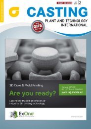
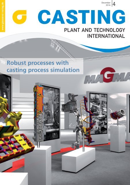
Robust processes with<br />
casting process simulation
www.bdguss.de<br />
Call for Papers<br />
5 th <strong>International</strong><br />
Cupola Conference<br />
CCS / Saarbrücken<br />
June, 22 – 23, 2017<br />
Foto: Küttner GmbH & Co. KG, Essen<br />
The deadline for submitting your abstract is<br />
set for December, 15 th , <strong>2016</strong><br />
To submit a paper, please provide a maximum<br />
300-word abstract along with the title of the paper,<br />
the speaker’s name and company / institute<br />
For further information please contact:<br />
Bundesverband der Deutschen<br />
Gießerei-Industrie (BDG)<br />
Simone Bednareck<br />
Hansaallee 203, 40549 Düsseldorf / Germany<br />
Phone: +49 (0) 211/6871-338<br />
Fax: +49 (0) 211/6871-40-338<br />
E-Mail: simone.bednareck@bdguss.de<br />
Contributions are invited<br />
in the following areas:<br />
> Raw materials<br />
> Metallurgy and melting process<br />
> Plant engineering<br />
> Control of process gases and<br />
detection<br />
> Energy efficiency<br />
> Emissions, environmental issues<br />
> Refractory materials<br />
> Holding furnaces<br />
> Modelling of processes
EDITORIAL K<br />
Light metal casting is enjoying<br />
a worldwide boom<br />
One year comes to a close, and another starts! One cannot really expect political<br />
stability on the global stage in 2017 in view of the unexpected election of<br />
Donald Trump as the next US President and a European Union weakened by<br />
Brexit. But this need not affect development of the world’s foundry sector –<br />
after all, Trump has promised to make the US economy strong again and to<br />
revive weak industries. Whether and when these promises will be kept remains<br />
to be seen. The announced US economic program, however, can only be a good<br />
thing for the world’s second-strongest foundry industry. Though a good position<br />
in the ranking of casting producers may be of little significance in the real<br />
world. Our author Douglas Trinowski has compared mold and core production<br />
by US casters with that of their colleagues in the EU and brings the statistics<br />
and rankings to life on P. 37.<br />
When examining the last two surveys by Modern Casting on global casting<br />
production (in 2013 and 2014) one common feature can immediately be seen:<br />
the quantity of aluminum castings produced is rising considerably – not that<br />
this is a great surprise given the developments towards light construction in<br />
the automotive and other sectors.<br />
Aluminum and other light metals also determine much of this issue of<br />
CASTING, whether in the form of an interview with the General Manager of<br />
the well-known die-casting machine producer Idra Riccardo Ferrario (from<br />
P. 6), an article on the innovative HZD zinc-casting foundry (which, thanks<br />
to its research, has created new materials and made interesting advances in<br />
functional integration, P. 20), or a report on the Swiss die-caster DGS Druckguss<br />
and its growth strategy for automotive structural castings (from P. 42).<br />
Then, among other things, there is an excellent article on the high-strength<br />
non-ferrous material Silafont-38 (P. 10) and a comprehensive specialist article<br />
on tungsten composite materials as mold materials for die casting, written by<br />
the Austrian Foundry Institute (ÖGI, from P. 24).<br />
One has already started celebrating Christmas in many parts of the world. I<br />
wish you a happy festive season in the names of all in the CASTING Editorial<br />
Office! Of more importance here, however, is the New Year’s festival that affects<br />
all of us – have a good new year and why not read CASTING again during the<br />
holiday period?<br />
Have a good read!<br />
Robert Piterek<br />
e-mail: robert.piterek@bdguss.de<br />
Casting Plant & Technology 4 / <strong>2016</strong> 3
K FEATURES<br />
INTERVIEW<br />
Ferrario, Riccardo<br />
Idra is leader again 6<br />
MATERIALS<br />
Röders, Andreas; Röders, Gerd; Wiesner, Stuart<br />
Practical application of high-strengh alloy Silafont-38 10<br />
MOLDING MATERIAL<br />
Dahlmann, Martin; Umla-Latz, Sabine; Wolff, Joachim<br />
High performance molding material for most accurate castings 14<br />
MELTING SHOP<br />
Dahmen, Michael<br />
Smart energy-efficient water recooling system is successfully employed<br />
in induction melting plants 16<br />
PRESSURE DIE CASTING<br />
Piterek, Robert<br />
The courage to carry out research 20<br />
Cover-Photo:<br />
MAGMA Gießereitechnologie GmbH<br />
Kackertstr. 11<br />
52072 Aachen<br />
Tel.: +49 241 88901 0<br />
Fax: +49 241 88901 60<br />
info@magmasoft.de<br />
www.magmasoft.de<br />
Read our Article “Optimization of a brake caliper”<br />
with MAGMA-casting process simulation on page 34 !<br />
Hofer, Peter; Gössl Wolfgang; Tucan, Klaus Peter; Gschwandtner, Reinhold;<br />
Schindelbacher, Gerhard; Schumacher, Peter<br />
Tungsten-based composites as a die material in high-pressure die-casting 24<br />
AUTOMATION<br />
Vollrath, Klaus<br />
The Olsberg foundry modernizes production of castings 30<br />
20<br />
30<br />
The pressure die-casting foundry Havelländische Zink-Druckguss<br />
GmbH & Co. KG is repositioning itself with innovative<br />
research, automation and digitalization (Photo: BDG/Piterek)<br />
The Olsberg foundry invested 11 million euros in new state-of-the-art<br />
plants for the production of iron castings. Heart of the investment is<br />
a powerful molding line which can meet high demands (Photo: HWS)
CASTING<br />
4 | <strong>2016</strong><br />
PLANT AND TECHNOLOGY<br />
INTERNATIONAL<br />
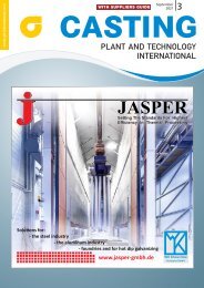
SIMULATION<br />
Wang, Houming; Wu, Shiguang<br />
Optimization of a brake caliper 34<br />
MARKETS<br />
Trinowski, Douglas<br />
Comparing moding and core making trends in the U. S. and<br />
EU casting industries 37<br />
COMPANY<br />
Vollrath, Klaus<br />
Aluminium structural castings: greater capacity for Europe‘s<br />
premium cars 42<br />
K COLUMNS<br />
Editorial 3<br />
News in brief 45<br />
Brochures 48<br />
Advertisers´ index/Fairs and congresses 50<br />
Preview/Imprint 51<br />
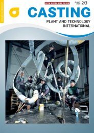
42<br />
DGS Druckguss Systeme AG, based in St. Gallen in Switzerland, is delivering large-format structural components for the hybrid<br />
body of Mercedes’ new C-Class. The next step is to build up production and logistical structures that meet the customer’s needs<br />
regarding development competence, component quality, production capacities and cost structures (Photo: Daimler AG)
K INTERVIEW<br />
Idra is leader again<br />
In the world of foundry, Idra stands for die casting; founded in 1946 by the Pasotti family, the<br />
company from Brescia has built its success on innovation and technological development becoming<br />
a point of reference since the 1960s, when the legendary “S” series represented the top<br />
for reliability, solidity and ease of use. At Travagliato establishment, near Brescia, an interview<br />
with CEO Eng. Riccardo Ferrario took place, a man of solid expertise in corporate turnarounds,<br />
with thirty years of experience in aluminium foundry<br />
Mr. Farrario, you have strongly rebuilt<br />
Idra. What is your summary today?<br />
When at the end of 2008 I was contacted<br />
to relaunch the company it seemed<br />
impossible to me that Idra was in difficulty,<br />
without orders and with negative<br />
perspectives; in fact, conditions<br />
of a potential revival could be seen.<br />
The majority of the company’s capital<br />
was acquired during the year by<br />
LK Machinery, an industrial giant listed<br />
on Hong Kong Stock Exchange and<br />
market leader in China for light alloys<br />
foundry, injection machines for<br />
plastic components and machining<br />
centers. LK held 70 % share capital,<br />
while remaining 30 % was controlled<br />
by Intesa Sanpaolo.The company had<br />
moved from the historic seat site to the<br />
new Triumplina to the new plant in<br />
Travagliato, just perfect for the production<br />
of small, medium and large presses.<br />
The brand was still strong, known<br />
throughout the world and its technology<br />
was even more valid.<br />
Riccardo Ferrario, General Manager of the Idra Group (Photos: Idra)<br />
But a very deep structural change was<br />
going on, to be evaluated very carefully,<br />
taking into account the characteristics<br />
of the control shareholder...<br />
In fact I spent a couple of months between<br />
account analysis and meetings<br />
with shareholders to understand their<br />
intentions and I decided to accept the<br />
challenge. The key moment was meeting<br />
Mr. Liù, founder and major shareholder<br />
of LK Machinery; I wanted to be<br />
sure first of all that LK’s objective was to<br />
relaunch and not to close the production<br />
activities in Italy. But Mr. Liù had<br />
clear ideas: he wanted to be the leader<br />
of “low cost” presses n the Chinese<br />
market, which already owned 60 %, and<br />
also dominate the entire product range,<br />
6 Casting Plant & Technology 4 / <strong>2016</strong>
View into the production halls of<br />
Idra, where a lean, process optimized<br />
organization determines the production<br />
of the die-casting machines<br />
with Idra presiding over the segment of<br />
high-tech presses for high-performance<br />
components. All this could be achieved<br />
only by keeping two distinct brands: LK<br />
for low cost machines and Idra for highend<br />
ones. No mingling between the two<br />
realities, even at trade and finance network<br />
level. The market had to understand<br />
that LK was only playing the role<br />
of shareholder. We would never have<br />
sold Idra presses in our historical markets<br />
or in China if the customer had<br />
considered us “Chinese style”.<br />
And this is how the adventure began,<br />
at a time certainly not easy for the<br />
metallurgical and manufacturing industry<br />
in Italy and Europe.<br />
I took the lead of the company in April<br />
2009. I had to do it quickly and well,<br />
the shareholder had no time and results<br />
were expected to arrive soon to<br />
prevent diversions. I had a good brand<br />
and I had to have a good product. The<br />
rest would have been supported by<br />
the Chinese shareholder, Idra’s men<br />
and my knowledge in the field. I convinced<br />
the shareholder to invest in the<br />
completion of the new series of OLS<br />
presses in that year, the most difficult<br />
for our industry, and I focused on commercial<br />
markets where we could sell,<br />
China first of all.<br />
How did Idra achieve results immediately?<br />
As a matter of fact, I still remember<br />
the skepticism that hovered among<br />
departments when I said that already<br />
in 2010 we would have lost no money,<br />
because we had everything to succeed:<br />
brand, product, the thrust of “made in<br />
Italy” and perfect shareholders for our<br />
relaunch: an industrial group that understands<br />
our product and the second<br />
Italian bank to support us in relaunch.<br />
I was right, we were able to reach<br />
breakeven in just 18 months, eliminating<br />
nearly 8 million losses, and making<br />
Casting Plant & Technology 4 / <strong>2016</strong> 7
K INTERVIEW<br />
profits by 2011. I’ll take the credit for<br />
bringing back confidence and enthusiasm<br />
in a magnificent group of people,<br />
the rest is thanks to them. With<br />
these results, all were convinced of<br />
the goodness of our choices, including<br />
trade unions.<br />
Certainly it hasn’t been easy to<br />
achieve competitiveness.<br />
It is true, Idra’s knowledge heritage<br />
was a security to create cutting-edge<br />
products, and perhaps it was more difficult<br />
to bridge the competitiveness<br />
gap on costs. Luckily I come from the<br />
school of the great Teksid of the ‘80s<br />
and I know that nothing happens by<br />
chance, but everything has to be conquered<br />
with fierce determination and<br />
great passion, starting from the people.<br />
When you start selling, that’s<br />
when the difficult part begins, the<br />
factory must follow you and adapt<br />
to new paces, quality must always<br />
be the focus of all choices and attention<br />
to induced costs and waste must<br />
be daily bread for everyone. Paying<br />
my dues in production for years has<br />
helped me, I could expect a lot from<br />
my coworkers because what I was asking<br />
them was what I used to do once.<br />
Zero business flights, spending review<br />
on everything, “lean organization”<br />
without intermediates, hunting for<br />
bottlenecks in the department to reduce<br />
lead time for deliveries in shorter<br />
times, outsourcing of non-core process<br />
steps.<br />
What about competition?<br />
Today it is not enough to produce well,<br />
you must offer a real competitive advantage<br />
to your customers, you have<br />
to think like them and offer them<br />
what they need to overcome their<br />
challenges. For example let’s consider<br />
after-sales service; we sell durable<br />
goods worth several some million<br />
euros, whose investment return relies<br />
heavily on production efficiency; in<br />
other words, machines should never<br />
stop and if they stop, we must be able<br />
to reactivate the operation in zero<br />
time. This is why we have focused on<br />
remote control service, which is done<br />
directly from Travagliato by tele-service,<br />
without the need for one of our<br />
technicians to go to our customer’s<br />
home, often flying hours from our<br />
offices. But this does not solve the<br />
problem, if the service is related to<br />
our Italian working time, so we created<br />
three service centers, one in Italy<br />
in our unique production site, one<br />
in USA in Idra NA North America subsidiary<br />
and a third in Idra China; so we<br />
can cover 24 hours.<br />
You have more than 9,000 presses<br />
running for more than 1,200 customers<br />
scattered in all parts of the world:<br />
how do you ensure them all timely<br />
assistance?<br />
Without inventing anything, but<br />
taking example from large multinationals,<br />
we created a mixed support<br />
network. We have three affiliates<br />
abroad controlled 100% by us,<br />
Idra NA North America, Idra Pressen<br />
in Germany and Idra China, and we<br />
have a number of Idra dealers in many<br />
countries, able to offer Idra qualified<br />
assistance. A presence that allows us<br />
to better meet any request for assistance.<br />
However, the secret is to make<br />
sure that the customer doesn’t call us,<br />
making him able to self-manage small<br />
problems. We don’t want to earn with<br />
assistance, nor have a customer who<br />
is a “prisoner”, always relying on us,<br />
we prefer having a competent customer<br />
that understands our presses<br />
and that manages them in complete<br />
autonomy with the best satisfaction.<br />
For this reason we teach our customers<br />
for free what to do; in 2011 we inaugurated<br />
ITC (Idra Technical Center)<br />
which provides free professional<br />
training courses to our clients. It’s a<br />
big investment in terms of resources<br />
and time, but it’s worth it because the<br />
customer tries to solve his problems<br />
with us and then he may apply what<br />
has been learnt at his home.<br />
You were talking about competitive<br />
advantage as the goal to be reached<br />
to sell your machines at remunerative<br />
prices. Can we take a deeper look into<br />
this topic?<br />
Our competitiveness arises from Idra’s<br />
approach to the market. When we ask<br />
the question: which car will our customer<br />
buy tomorrow, we immediately<br />
try to know which products he must<br />
provide for his end customers. In essence,<br />
it is no longer enough to focus<br />
on direct customer’s needs, but<br />
we need to be farsighted and analyze<br />
which pieces the client will produce<br />
in the near future. Without this vision<br />
we may set wrong strategies. Let’s consider<br />
a very simple case: does it make<br />
sense to develop a more advanced<br />
press for the production of aluminium<br />
radiators? Maybe not, maybe it’s useful<br />
to invest elsewhere. At Idra we had<br />
correctly evaluated the enormous development<br />
of structural components<br />
in light alloy castings in the field of<br />
transport, and in advance of competition<br />
and the current market boom<br />
in 2010 we produced NoX presses (no<br />
oxidation), able to work in high vacuum<br />
conditions; without contact with<br />
air aluminum can’t oxidize, and so<br />
castings will not contain inclusions<br />
of oxide or air entrapment, therefore<br />
it can be subjected to heat treatment<br />
to improve its mechanical properties,<br />
as required by the designers of new<br />
bodies and suspensions of cars. And<br />
what’s more, demand is now directed<br />
towards products with increasingly<br />
thin walls, from 4 to 2 mm or less,<br />
and so we have developed an injection<br />
system that can develop more than<br />
10 m/s speed in second phase also for<br />
presses of more than 4,000 t, in such a<br />
way that the alloy fills the mold cavity<br />
very simply. And today the market<br />
rewards us, just think about the<br />
Ford Mondeo’s hatchback which is<br />
produced only on Idra presses, or the<br />
Mini’s knee blocker and the Range<br />
Rover’s front.<br />
Concerning the market outlook for<br />
quality castings for the automotive<br />
sector, there aren’t only structural<br />
components, we also remember<br />
continuous lightening of the engine,<br />
which has focused the attention of designers<br />
on light-alloy engine blocks;<br />
do you have any developments and<br />
news in this specific sector?<br />
Today Idra has more than 100 presses<br />
that produce light-alloy engine blocks<br />
in all major car producing countries,<br />
but I must say that we are particularly<br />
proud for the order received from<br />
8 Casting Plant & Technology 4 / <strong>2016</strong>
Teksid from Fiat-Chrysler Group at<br />
the end of 2013 as unique supplier<br />
of new engine blocks for Italian and<br />
Brazilian factories of the group. The<br />
match was not easy: Fiat-Chrysler has<br />
compared the best press manufacturers<br />
and thoroughly analyzed all technical<br />
and service aspects before making<br />
its choice. There is no doubt that<br />
other factors being equal, our technology<br />
and after-sales service, which<br />
are our flagship, have made the difference.<br />
One last point: Idra is now 100 % Chinese,<br />
with a unique shareholder that<br />
has taken over remaining 30% first<br />
owned by Intesa Sanpaolo. Aren’t<br />
you worried about this situation?<br />
In the light of my experience during<br />
the last five years, I can assure you<br />
that I am proud of this Italian business,<br />
owned by a Chinese company;<br />
it’s the clear proof that you can do<br />
business in Italy, despite difficulties.<br />
Funds are moved quickly from one<br />
side to another of the globe, it is important<br />
not to move production sites<br />
and, in our case, it’s important for<br />
Idra to keep thinking head and production<br />
in Italy; this is why we don’t<br />
worry, and results give us confidence<br />
in this respect, we must just remember<br />
that there are no situation rents<br />
and that success must be conquered<br />
day after day. China has represented<br />
Idra’s salvation, frankly if my predecessor<br />
hadn’t found a buyer willing<br />
to invest in the company, today we<br />
wouldn’t be here telling this small but<br />
significant piece of company history.<br />
Then we found on a silver platter the<br />
keys of the Chinese market, with directions<br />
on where and to whom to sell our<br />
products in the years of profound crises,<br />
I am referring to 2009 and 2010.<br />
Without all this we would not have<br />
had the necessary speed to balance our<br />
accounts in less than two years. And<br />
a good period awaits us, as long as we<br />
continue working on innovation and<br />
we maintain a positive gap compared<br />
to competition.<br />
www.idragroup.com<br />
Casting Plant & Technology 4/ <strong>2016</strong> 9
K MATERIALS<br />
Authors: Gerd and Andreas Röders, G. A. Röders GmbH & Co. KG, Soltau; Stuart Wiesner, Rheinfelden Alloys GmbH &<br />
Co. KG, Rheinfelden<br />
Practical application of highstrength<br />
alloy Silafont-38<br />
The newly developed, high-strength alloy Silafont-38 was tested in a casting trial at the foundry<br />
G.A. Röders, Soltau, Germany. In a thin-section structural casting, the material properties were<br />
better than specified. Aspects examined in the context of the tests included the heat treatment<br />
practice, the metallurgical properties, riveting and welding behaviour as well as corrosion resistance<br />
of the alloy<br />
In lightweight engineering of structural<br />
components the requirements on material<br />
properties are becoming increasingly<br />
more exacting. One objective is to<br />
achieve increasingly higher strengths in<br />
order to build structures of ever smaller<br />
section thicknesses. As a result of<br />
optimizations in the pressure die casting<br />
process and heat treatment practice,<br />
the potential of the standard alloy<br />
AlSi10MnMg has been continuously<br />
widened. By modifying the alloy and<br />
applying new heat treatment methods,<br />
it is possible to even further expand the<br />
applicability of this alloy.<br />
The tested part<br />
The tests were made on one of the structural<br />
parts, which the foundry G. A. Röders<br />
makes for Fastner Leicht metalltechnik,<br />
Ilsfeld-Auenstein, Ger many, and which<br />
is used in the Audi R8. Figures 1a and<br />
b show the approx. 300-mm-long component.<br />
It must meet the specifications<br />
applicable to crash-relevant components<br />
with section thicknesses of up to 2.0<br />
mm. G.A. Röders produces this challenging<br />
casting in series using the alloy Silafont-36<br />
(EN AC-AlSi10MnMg). In addition<br />
to the relevant material properties,<br />
the part must provide good weldability.<br />
Thin-walled structural component made of a high-strength Silafont-38 alloy tested<br />
at G. A. Röders in a practical casting test (Photos and Graphics: Rheinfelden Alloys)<br />
The alloy<br />
When developing the alloy Silafont-38,<br />
special emphasis was placed on castability,<br />
which is more or less the same<br />
as that of Silafont-36. The contained<br />
zinc improves mold filling performance.<br />
The addition of iron and manganese<br />
reduces stickiness. Casting trials<br />
have confirmed the good casting properties<br />
of Silafont-38. Due to the alloy’s<br />
good flowability, there was a slight tendency<br />
towards greater flash formation.<br />
However, the results of X-ray examinations<br />
and blister tests were just as good<br />
as those obtained from Silafont-36. The<br />
increase in strength after a heat treatment<br />
is predominantly due to a magnesium-copper<br />
ratio, which suppresses the<br />
development of corrosive phases. Highmelting-point<br />
phases promote the formation<br />
of ultrafine eutectic structures.<br />
Heat treatment<br />
In its technology centre, the foundry<br />
Rheinfelden Alloys, located in southern<br />
Germany, casts different plates and<br />
a case with fins as test pieces. A comparison<br />
was made between material properties<br />
achievable in test plates of 3 mm<br />
thickness and in structural castings with<br />
extensive surface areas. While the similarities<br />
in mold filling of such plates<br />
and of large, high-quality structural<br />
parts were greater than expected, there<br />
were great differences in the quenching<br />
rates of the castings after removal<br />
from the molds and after the heat treatment.<br />
Small plates can be quenched<br />
at distinctly higher rates, with a corresponding<br />
effect on the material properties.<br />
For this reason, the heat treatment<br />
was modified such that the quenching<br />
conditions were very much like those<br />
10 Casting Plant & Technology 4 / <strong>2016</strong>
Figure 1: Front (a) and back (b) of<br />
the component joined by rivets<br />
a<br />
b<br />
found in industrial manufacturing processes.<br />
Within the context of this simple<br />
modification, the maximum quenching<br />
rate was set at 3 °C/s. Figure 2 shows the<br />
temperature curves of 3-mm plates under<br />
different quenching conditions. The<br />
measured material values correspond<br />
largely to those measured in standardized,<br />
industrial production processes.<br />
Aluminium heat treatment specialists<br />
Belte AG, Delbrück, Germany, applied<br />
High Speed Air Quenching (HISAQ) and<br />
an Aluquench treatment. The HISAQ<br />
temperature curve, which was measured<br />
by a trailing element, is shown in<br />
figure 2. The Aluquench method uses<br />
a polymer as quenching medium. The<br />
corresponding temperature curve runs<br />
very close to that of water quenching.<br />
This method achieved very good material<br />
values.<br />
Material specifications<br />
The target was to achieve a yield<br />
strength of 180 N/mm² and an elongation<br />
at fracture of at least 8 %. With<br />
the casting technology developed at<br />
the G.A. Röders foundry, the material<br />
values were even better than specified<br />
(Figure 3). Plotted here are the mean<br />
values from approx. 50 tensile tests.<br />
G.A. Röders boasts vast knowhow in<br />
vacuum technology and in designing<br />
and producing casting molds. For the<br />
tests, only the alloy was changed, all<br />
casting parameters remained the same.<br />
Figure 2: Quenching tests<br />
Riveting and welding<br />
The strength of a material also has an<br />
effect on its rivet setting performance.<br />
Higher strength materials require different<br />
rivets than materials of lower<br />
strength. Therefore, the geometry and<br />
parameters of the rivets were adjusted<br />
to suit the properties of Silafont-38.<br />
Thanks to the high ductility of Silafont-38,<br />
the riveted joints are crack-free<br />
(Figures 1 a and b as well as Figure 4).<br />
The materials are joined by self-pierce<br />
riveting, i.e. semi-tubular rivets set by<br />
means of riveting tongs. G.A. Röders<br />
Figure 3: Material specifications of Silafont-38<br />
tested the weldability of the new alloy<br />
by a welding test during production.<br />
For the test, the respective area of the<br />
material was fusion-welded by tungsten<br />
inert-gas (TIG) welding and the surface<br />
of the thus produced welded seam investigated.<br />
Despite the zinc contained<br />
in the material, this test showed that<br />
weldability was just as good as that of<br />
the standard alloy Silafont-36.<br />
Casting Plant & Technology 4 / <strong>2016</strong> 11
K MATERIALS<br />
Figure 4: Microsection through the rivet<br />
Figure 5: Microstructure in stage F<br />
Figure 6: Microstructure in stage T6<br />
Metallurgy and phase simulation<br />
Figures 5 and 6 show microsections<br />
of the part at a magnification of 500.<br />
The stage designated as “F” is characterized<br />
by an ultrafine eutectic structure,<br />
which provides fairly good formability<br />
already in the as-cast state. The<br />
intermetallic phases are very small (below<br />
10 µm) and evenly distributed. After<br />
a T6 heat treatment, the eutectic<br />
has a spheroized structure providing<br />
for high ductility. Figure 7 shows the<br />
quasistatic state simulated with the<br />
JMatPro software on the basis of the<br />
Calphad databases. The here presented<br />
phases are generally large enough<br />
to show in a micrograph. The Si-containing<br />
eutectic phase plays a central<br />
role in the alloy. A finely distributed<br />
AlMnFeSi phase (alpha) is required<br />
to achieve high ductility. Other highmelting-point,<br />
intermetallic phases<br />
influence the fineness of the microstructure.<br />
In the investigated alloy, the<br />
Mg2Si eutectic does not precipitate as a<br />
Figure 7: Quasistatic phase simulation<br />
major phase. Submicroscopic precipitations<br />
in the aluminium phase have a<br />
significant effect on the strength of the<br />
material. Such precipitations can also<br />
be calculated within the context of a<br />
phase simulation by JMatPro. Figure 8<br />
shows metastable MgSi phases, which<br />
are decisive for the strength properties<br />
12 Casting Plant & Technology 4 / <strong>2016</strong>
of the material. The characteristics of<br />
such phases depend on the initial material<br />
state (as-cast or heat treated) and<br />
the quenching conditions. If those<br />
phases have the right size, they give<br />
the material high strengths.<br />
Corrosion resistance<br />
A salt spray test under alternating conditions<br />
(ISO 9227) and an intergranular<br />
corrosion test (ASTM G110-92)<br />
were conducted at the Steinbeis Centre<br />
in Friedrichshafen, Germany. The<br />
corrosive behaviour of 3-mm plates<br />
made of Silafont-38 was examined<br />
and compared with the corresponding<br />
behaviour of other alloys provided<br />
by Rheinfelden Alloys. Evaluations of<br />
336 hours of salt spray testing showed<br />
that the resistance to corrosion is appropriate<br />
and similar, for example, to<br />
that of Castasil-37 (AlSi9MnMoZr).<br />
While high-purity alloys predominantly<br />
corrode in the form of pitting,<br />
Figure 8: Dynamic phase simulation<br />
corrosion of Silafont-38 extends over a<br />
wider area.<br />
http://rheinfelden-alloys.eu<br />
Casting Plant & Technology 4 / <strong>2016</strong> 13
K MOLDING MATERIAL<br />
Authors: Martin Dahlmann and Sabine Umla-Latz, Hüttenes-Albertus, Düsseldorf, and Joachim Wolff, Imerys Refractory<br />
Minerals, Paris<br />
High performance molding material<br />
for most accurate castings<br />
Complex cast parts such as turbocharger housings play a central role in the design of modern<br />
high-performance engines. Due to its particular characteristics silica sand has its limits as a molding<br />
material when it comes to casting finely structured components, reduced wall thicknesses<br />
and perfect surfaces. Thanks to its high temperature load strength and a strong resistance to<br />
metal penetration, Kerphalite KF, a special sand, has proven itself suitable for these types of applications<br />
in many foundries<br />
In central Europe, silica sand is available<br />
in large quantities and in good<br />
qualities, and is widely used in foundries<br />
as an economical basic molding<br />
material. But it also has negative properties,<br />
which may lead to problems<br />
when producing sophisticated castings.<br />
These particularly include the socalled<br />
quartz inversion, i.e. the abrupt<br />
expansion of the specific volume at 573<br />
°C. It occurs during virtually every casting<br />
process and may lead to sand expansion<br />
defects, mainly in the form of finning<br />
(also called veining). The molding<br />
material can crack under high temperature<br />
load, allowing liquid metal to seep<br />
into the resulting cracks and cavities.<br />
Suitable alternative for silica<br />
sand<br />
Foundries aim to avoid these casting defects<br />
and reduce the costly effort needed<br />
Andalusite mining in Brittany, France. The name Kerphalite derives from the<br />
Guerphalès deposit in Brittany (Photo: Imerys Refractory Minerals)<br />
to rework the casting. This is all the more<br />
important when considering that casting<br />
geometries are becoming ever more<br />
complex and the demands for their dimensional<br />
accuracy and surface quality<br />
are becoming ever more exacting.<br />
If foundries want to avoid using more<br />
binding agents or adding gas-forming<br />
additives, they need a suitable alternative<br />
to silica sand as a molding material.<br />
Kerphalite KF is a special sand with<br />
low thermal expansion, high refractoriness<br />
and a special grain geometry that<br />
enables very high core surface densities.<br />
Figure 1: Andalusite crystals in rock (Photo: C.A.R.R.D)<br />
Figure 2: The final product for use in the foundry in big<br />
bags (Photo: Hüttenes-Albertus)<br />
14 Casting Plant & Technology 4 / <strong>2016</strong>
Mineralogical composition<br />
Andalusite<br />
Bulk density<br />
1.55 g/cm³<br />
Refractoriness SK > 36 ≥1830 °C<br />
lin. expansion coefficient α 20- 600°C 6.5 · 10 -6 K -1<br />
Average grain size<br />
0.23 mm or 0.20 mm<br />
AFS Grain Fineness Number 60 ± 5 or 70 ± 5<br />
Grain form<br />
angular<br />
Core production<br />
with all binder systems<br />
Table 1: Properties of Kerphalite KF<br />
Figure 3: Sand core for a turbine housing<br />
(Photo: Harz Guss Zorge GmbH)<br />
From stalky crystals to a special<br />
sand<br />
Kerphalite KF is a natural material based<br />
on andalusite. Andalusite was first identified<br />
in 1798 and named after the Spanish<br />
province, Andalusia, though later<br />
this location turned out to be untypical<br />
for the mineral. In terms of its chemistry,<br />
andalusite is an aluminium silicate<br />
(Al 2<br />
SiO 5<br />
), which crystallizes in the ortho -<br />
rhombic crystal system and usually develops<br />
elongated, prismatic crystals with<br />
a square cross-section (Figure 1).<br />
When a water distribution network was<br />
built in the north of Brittany, France in the<br />
1960s, schist layers with aluminium silicate<br />
inclusions – andalusite – came to light.<br />
Today, Imerys Refractory Minerals<br />
mines treats and processes the andalusite<br />
in Brittany. The deposit is four kilometres<br />
south of Glomel and comprises several<br />
pits that are exploited in the form of terraces.<br />
Imerys Refractory Minerals mines<br />
about one million tons of stone per year.<br />
At the end of the multi-step and highly<br />
complex production process (breaking,<br />
grinding, separating, calcination and<br />
floatation), 80,000 tons of andalusite are<br />
extracted. Several thousand tons of Kerphalite<br />
KF are used as a special sand for<br />
foundry applications across the world.<br />
Processable with all binder systems<br />
and molding processes<br />
Kerphalite KF has a low density (similar to<br />
silica sand) and can be used in pure form<br />
or as blend with silica sand, as required.<br />
When blended, the share of Kerphalite<br />
KF should be between 30 and 100 %. In<br />
this way, the user is able to adjust the sand<br />
blend to be both cost-effective and process<br />
efficient. The special sand blends are<br />
easily processable with all common binder<br />
systems. They are suitable for the Cold-<br />
Box as well as for the shell molding process<br />
or the furan no-bake process – in iron<br />
as well as in steel castings. Kerphalite KF<br />
has also been used for 3-D printing cores<br />
for over ten years.<br />
Strong partnerships for success<br />
The partnership with Hüttenes-Albertus<br />
has been decisive for the development of<br />
Kerphalite as a special sand for the most<br />
accurate castings in the European foundry<br />
industry. In the mid-1980s, Hüttenes-Albertus<br />
added Kerphalite to its product<br />
portfolio, and has been actively promoting<br />
the material’s advantages as a molding<br />
material in the market ever since. HA’s<br />
expertise in core production technology<br />
as well as its extensive distribution network<br />
have contributed to establishing<br />
Kerphalite as a benchmark in the European<br />
foundry industry. Today, the special<br />
sand is used in a large number of foundries<br />
in Germany, France and many other<br />
European countries (Figure 2).<br />
Dense core surfaces, low thermal<br />
expansion<br />
There are two special properties that<br />
make Kerphalite KF a sought-after<br />
molding material for difficult casting<br />
jobs. First of all, the low and linear<br />
thermal expansion plays, of course,<br />
an important role as following example<br />
shows: A 400-mm-long canal core<br />
made of silica sand, if fully heated<br />
to a casting temperature of 1380 °C,<br />
would expand by a total of 9.3 mm.<br />
This means the core either develops<br />
thermal fatigue cracking resulting in<br />
finning on the casting, or it bends or<br />
breaks. However, when using Kerphalite<br />
KF as a molding material, the core<br />
would only expand by 3.8 mm under<br />
the same conditions.<br />
Secondly, the broken grains of the orthorhombic<br />
crystal with their angular<br />
cross section create a highly dense core<br />
or mold surface. This effectively helps to<br />
prevent the penetration of liquid metal,<br />
especially in comparison to cores that<br />
are produced from spherical sand grains<br />
of the same average grain size (Table 1).<br />
Proven applications in<br />
foundries<br />
Typical applications for Kerphalite KF are<br />
cores for hydraulic valve housings, canal<br />
and water jacket cores for cylinders and<br />
cylinder heads, also subsections of the<br />
water jacket core (as key core), as well as<br />
cores for the helical turbine housing of<br />
the turbochargers. In all of these cases it<br />
is important to create fine, thin-walled<br />
and dimensionally accurate casting parts<br />
with flawless surfaces.<br />
Foundries, such as Harz Guss Zorge,<br />
Zorge, Germany, and many others, rely<br />
on this special sand for casting turbine<br />
housings and cylinder heads. The casting<br />
has a complex geometry and has to<br />
withstand high thermal loads to fulfil<br />
its important function in the end product,<br />
the turbocharger. The turbine housing<br />
has to meet the highest quality standards<br />
in order to achieve effective flow<br />
behaviour. It is imperative to have a reliable<br />
procedure to avoid finning, because<br />
subsequent cleaning requires a lot of effort<br />
or re-work is impossible (Figure 3).<br />
When using Kerphalite KF as a molding<br />
material, foundries are on the safe<br />
side. They achieve a core with the lowest<br />
thermal expansion and the highest surface<br />
quality, able to withstand high casting<br />
temperatures even in the most critical<br />
areas: a core that meets all requirements<br />
for producing a perfect cast part for a<br />
high-quality, high-performance product.<br />
www.huettenes-albertus.com<br />
www.imerys-refractoryminerals.com<br />
Casting Plant & Technology 4 / <strong>2016</strong> 15
K MELTING SHOP<br />
Author: Michael Dahmen, Otto Junker GmbH, Simmerath-Lammersdorf<br />
Smart energy-efficient water recooling<br />
system is successfully employed<br />
in induction melting plants<br />
For an induction melting furnace to operate safely, a powerful water cooling system must be in<br />
place to prevent overheating of the induction coil, the frequency converter and the capacitors.<br />
In this context, particular importance is attached to a low energy consumption of the cooling<br />
water pumps and fans of the air cooler or evaporative cooler as well as to the capability of recovering<br />
a large amount of heat from the cooling water<br />
Typical pump frames of a water recooling system for a high-performance melting plant<br />
(Photos and Graphics: Otto Junker)<br />
16 Casting Plant & Technology 4/<strong>2016</strong>
Thanks to numerous developments,<br />
induction furnace technology has<br />
reached a high overall level of efficiency.<br />
In cast iron melting, the efficiency<br />
rate may amount to as much<br />
as 75 % (Figure 1).<br />
Power dissipation occurs mainly<br />
in the form of ohmic losses from<br />
the coil and electrical system, whereas<br />
thermal losses are low. In cast iron<br />
melting these ohmic losses amount<br />
to approx. 20 - 25 % of the power input,<br />
while for copper the figure goes<br />
up to as much as 35 - 40 %. Thus, in<br />
a cast iron melting furnace with an<br />
8 MW power rating, the amount of<br />
power dissipated as heat will be in<br />
the order of approx. 2 MW. This high<br />
amount of waste heat must be reliably<br />
transferred away via a powerful<br />
water recooling system to maintain<br />
an appropriately low water temperature<br />
in the supply line. Needless to<br />
say, intense research efforts are being<br />
made to reduce ohmic losses further.<br />
Thus, reductions by 4 % and 9<br />
% have been achieved, depending on<br />
the metal being melted, through the<br />
use of a special coil design.<br />
A second option is to recover, and<br />
hence re-use, the large quantity of<br />
heat carried in the system’s cooling<br />
water. It should be noted here that<br />
heat recovery works best at an elevated<br />
cooling water temperature which<br />
should, moreover, remain as constant<br />
as possible. At the same time,<br />
the energy consumption of the cooling<br />
water pumps and of the fans serving<br />
the air cooler or evaporative cooler<br />
should be reduced.<br />
The basic parameters in rating a<br />
water recooling system are the water<br />
demand of the components to be<br />
cooled, the maximum supply and<br />
return temperatures, and the acceptable<br />
temperature rise. In some<br />
cases, two mutually independent<br />
closed cooling circuits are employed<br />
in view of the different water quality<br />
requirements for cooling the furnace<br />
and for cooling the electrical equipment<br />
(converter, capacitors). Often<br />
the furnace and the electrical system<br />
are served by one common cooling<br />
circuit, especially where IGBT converters<br />
are used. The water recooling<br />
system is dimensioned and its operating<br />
regime is designed for the full<br />
rated power of the melting furnace<br />
plus a defined safety margin. The acceptable<br />
temperature limits, which<br />
amount to 85 °C for the furnace coil<br />
and 45 °C for the electric circuit,<br />
must not be exceeded.<br />
As the cooling water pumps run at<br />
full speed regardless of the amount of<br />
heat actually dissipated, the system<br />
continues to deliver its full cooling<br />
output even in operating modes such<br />
as, e.g., holding the melt at temperature<br />
or shutting down the furnace. As<br />
a result, the return water temperature<br />
in the coil circuit will drop while<br />
the electric power demand remains<br />
unnecessarily high. The drawbacks<br />
of this former practice can be summarized<br />
thus:<br />
» varying return water temperatures<br />
» temporarily low temperature level<br />
» unnecessary power consumption<br />
of the pumps in the water recooling<br />
system<br />
The new approach<br />
Together, Otto Junker und Induga,<br />
both Simmerath, Germany, have<br />
developed the intelligent water recooling<br />
system referred to as SmartReCooler<br />
(SRC) which adapts its<br />
cooling output to the actual heat<br />
losses of the induction furnace installation.<br />
The system’s cooling output is<br />
proportional to the temperature rise<br />
and flow rate of the cooling water. It<br />
supplies just the right cooling water<br />
Figure 1: Typical energy flow diagram of a cast iron melting process<br />
throughput for the current cooling<br />
requirement, thereby maintaining<br />
return water temperatures constant<br />
and keeping the water recooling system<br />
energy-efficient. Pump speeds<br />
are determined by a smart controller.<br />
As the control unit also takes into<br />
account the furnace’s electric power<br />
input, the cooling system responds<br />
very quickly to new furnace operating<br />
conditions.<br />
In circumstances requiring only<br />
little heat to be removed, e.g., when<br />
the furnace is shut down and allowed<br />
to cool over several hours, the system<br />
runs in energy-saving mode. In this<br />
mode it keeps up a minimum water<br />
supply that suffices for all cooling<br />
circuits. The SRC system can respond<br />
autonomously to new heat loss sit-<br />
Casting Plant & Technology 4/<strong>2016</strong> 17
K MELTING SHOP<br />
Figure 2: SmartReCooler system screen<br />
uations at any time. In energy saving<br />
mode the cooling water pumps<br />
draw very low power, i.e., very little<br />
electricity is consumed. The energy<br />
saving potential depends very much<br />
on the furnace operating regime, i.e.,<br />
on how long the furnaces are run in<br />
holding or cool-down mode or with<br />
reduced power input.<br />
At KSB AG, the leading manufacturer<br />
of pumps and pump systems, this<br />
new technology was used on one of<br />
two identically designed Monomelt<br />
furnaces with independent water recooling<br />
circuits which had been ordered<br />
for the company’s Pegnitz site.<br />
As one furnace plant featured the<br />
smart SRC system while the other<br />
was equipped with traditional water<br />
recooling, the benefits of the new system<br />
could be objectively evaluated.<br />
The furnaces are designed to melt<br />
both cast-iron and steel. Each of<br />
the two plants consists of a 2-tonne<br />
coreless induction furnace with an<br />
IGBT converter rated for 1,500 kW.<br />
The nominal frequency can be set at<br />
500 or 125 Hz. The installations are<br />
equipped with a JOKS melt processor,<br />
a weigh scale, extractor hoods<br />
and a hydraulic power pack.<br />
The water recooling system of<br />
each melting furnace has separate<br />
cooling circuits for the furnace and<br />
the electrical equipment and uses a<br />
glycol-free water-to-air cooler. The<br />
pump rack in the furnace circuit carries<br />
two 7.5 kW pumps operating in<br />
a redundant mode. The cooling cir-<br />
IMERYS<br />
REFRACTORY MINERALS<br />
FOR FOUNDRY APPLICATIONS<br />
INVESTMENT<br />
CASTING<br />
REFRACTORY FLOURS<br />
& STUCCOS<br />
SAND<br />
CASTING<br />
SANDS FOR<br />
CORES & MOULDS<br />
FILLERS FOR<br />
FOUNDRY COATING<br />
PUB IRM FFA EXE OK.indd 1 05/01/<strong>2016</strong> 11:58:36<br />
18 Casting Plant & Technology 4/<strong>2016</strong>
cuit for the electrical equipment uses<br />
only one pump of the same rating.<br />
The water recooling system is controlled<br />
by the furnace PLC via a remote<br />
substation.<br />
The extra hardware to be fitted for<br />
the SRC system consisted only of<br />
the variable frequency drive units<br />
for the two furnace-circuit pumps, a<br />
few temperature sensors, and some<br />
small accessories. This was in addition,<br />
needless to say, to the new<br />
smart software developed for the application.<br />
This software ensures that<br />
the cooling water flow rate is adapted<br />
at once when the cooling water<br />
demand changes suddenly, e.g., because<br />
the furnace is set to full power<br />
by the operator or the load shedding<br />
system. A simple control scheme<br />
based on water temperatures alone<br />
had been found inadequate. Figure<br />
2 shows a typical screen menu, albeit<br />
for a solution based on a water-to-water<br />
cooler.<br />
A water-to-water cooler fed from<br />
the municipal water supply is fitted<br />
CALCINED CLAYS<br />
MOLOCHITE TM<br />
CLAYRAC TM<br />
MULGRAIN ® 47<br />
MULLITE &<br />
ANDALUSITE<br />
MULGRAIN ® 60<br />
KERPHALITE TM<br />
WHITE<br />
FUSED MULLITE<br />
FUSED ZIRCONIA<br />
MULLITE<br />
in the electrical equipment cooling<br />
circuit for the event that the air temperature<br />
exceeds 30 °C and the water-to-air<br />
cooler can no longer adequately<br />
cool the more heat-sensitive<br />
converter assembly. For heat recovery,<br />
a plate-type heat exchanger is integrated<br />
into the circuit.<br />
By now the two Monomelt systems<br />
have been in operation for five<br />
months, and a first comparison between<br />
the traditional and new water<br />
recooling systems can be made.<br />
Considering the different service<br />
conditions of the two furnace systems<br />
it can be said that the variable-frequency<br />
drive units of the<br />
cooling water pumps save a lot of<br />
energy. Thanks to the use of the SRC<br />
the energy consumption of the water<br />
recooling system could be reduced<br />
by more than 30 %.<br />
Thomas Wagner of KSB AG’s Pegnitz-based<br />
foundry production engineering<br />
unit had this comment:<br />
“The scheme using VFD-controlled<br />
pumps in the cooling circuit has<br />
FUSED SILICA<br />
TECOSIL ®<br />
ALUMINAS<br />
WHITE<br />
FUSED ALUMINA<br />
BROWN FUSED<br />
ALUMINA<br />
BUBBLE<br />
ALUMINA<br />
proved a full success at our site. In the<br />
five months since the melting system<br />
was commissioned, we have benefited<br />
from a trouble-free operation and<br />
substantial energy savings. In our<br />
production conditions, we save so<br />
much power that the extra cost of<br />
frequency-controlling the cooling<br />
pumps will be recovered within just<br />
about one year. KSB AG now plans to<br />
retrofit the second coreless induction<br />
furnace, which does not yet feature<br />
frequency control of the cooling water<br />
pumps, to this new technology.”<br />
Moreover, the new system has led to<br />
higher and more constant water temperatures,<br />
which augurs well for the<br />
intended installation of a waste heat<br />
recovery system.<br />
Conclusion<br />
The smart SRC system has successfully<br />
proven itself in practice and the<br />
specified targets were achieved. The<br />
use of this control scheme clearly increases<br />
the energy efficiency of a water<br />
recooling system, apart from delivering<br />
a constant temperature that<br />
facilitates energy recovery. Further<br />
benefits include a rapid adjustment<br />
to the melting furnace’s operating regime<br />
plus an extended service life of<br />
cooling system components. In all,<br />
the economic benefits yield a short<br />
payback period. These advantages<br />
are confirmed by the fact that KSB<br />
AG now aims to convert its second<br />
melting furnace to this technology<br />
as well.<br />
It remains to be noted that a conversion<br />
of existing water recooling<br />
circuits to the new system can take<br />
place at short notice and with little<br />
installation effort. Work is now<br />
ongoing to realize this system for<br />
Duomelt applications as well (two<br />
furnaces, one frequency converter)<br />
and a solution for controlling the<br />
fans of the air cooler or evaporative<br />
cooler is in preparation. The system<br />
is also suitable for use on other water-cooled<br />
thermoprocessing equipment.<br />
www.otto-junker-group.com/de<br />
www.induga.com<br />
PUB IRM FFA EXE OK.indd 2 05/01/<strong>2016</strong> 11:58:40<br />
Casting Plant & Technology 4/<strong>2016</strong> 19
K PRESSURE DIE CASTING<br />
Author: Robert Piterek, Germany Foundry Association, Düsseldorf<br />
The courage to carry out research<br />
The pressure die-casting foundry Havelländische Zink-Druckguss GmbH & Co. KG in Premnitz,<br />
Germany, is repositioning itself for the future with innovative research, automation and digitalization.<br />
The company also wants to score with zinc as a light-construction material<br />
A casting cell at HZD in Premnitz: the company has 100 personnel working on the die-casting machines, in processing,<br />
in tool construction or in administration (Photos: BDG/Piterek)<br />
For some time now a tree with filigree<br />
zinc leaves has been standing at the German<br />
Foundry Association in Düsseldorf<br />
– on permanent loan from Havelländische<br />
Zink-Druckguss (HZD) in Premnitz,<br />
who used it to demonstrate their<br />
competence in thin-walled casting at<br />
the EUROGUSS trade fair in <strong>2016</strong>. The<br />
innovative company has one particular<br />
aim: “the term ‘weight reduction’<br />
should immediately be linked with<br />
HZD,” Oliver Ganschar, the new Works<br />
Manager of the zinc die-casting foundry<br />
in western Brandenburg, puts it in a nutshell.<br />
Ganschar and Commercial Manager<br />
Raiko Hentze have recently become<br />
the lead team of Petar Marovic, who last<br />
year became Managing Director of the<br />
foundry and started running it as the<br />
Managing Partner in <strong>2016</strong>.<br />
The company has steadily grown<br />
since its founding in 1991: the workforce<br />
has increased to about 100 employees<br />
today – a success story for the<br />
structurally weak region on the River<br />
Havel. HZD currently produces about<br />
3,000 articles for roughly 200 customers,<br />
making 3,000 tonnes of zinc castings<br />
every year and increasing overall<br />
sales to a current level of 17.4 million<br />
euros. The zinc experts from Havelland<br />
share the market with companies such<br />
as HDO Druckguss- und Oberflächentechnik<br />
GmbH in Paderborn, Adolf Föhl<br />
GmbH + Co KG in Rudersberg-Necklinsberg,<br />
and G.A.Röders GmbH & Co. KG<br />
in Soltau.<br />
22 die-casting machines with clamping<br />
forces of between 7.5 and 200 tonnes<br />
20 Casting Plant & Technology 4 / <strong>2016</strong>
are at work in the production hall, mainly<br />
models from foundry machinery constructor<br />
Oskar Frech. The personnel<br />
work in three shifts, producing castings<br />
made of the zinc alloys Z410 and Z430 in<br />
a weight range of between 0.1 g - 2 kg.<br />
The customers come from the automotive<br />
sector; the household appliances,<br />
plumbing, fittings and drives industries;<br />
locking technology and electrical<br />
engineering.<br />
Up to 40 castings are created with just<br />
one shot when the permanent molds of<br />
the die-casting machines close with a<br />
hydraulic hiss and the hot zinc is shot<br />
into the cavities. Batch sizes at HZD<br />
range from 50 to several hundred thousand<br />
units. Stay bearings, for example,<br />
that are used for tipping windows, are<br />
a classic of mass production. Either unmachined<br />
parts or finished components<br />
are delivered, depending on customer<br />
requirements. When necessary, the<br />
Premnitz-based company also sets up<br />
and manages the supply chain.<br />
At first glance, HZD is a completely<br />
normal company like numerous others<br />
in Germany. But something is different<br />
here. This can be seen straightaway<br />
from the many prizes that the SME regularly<br />
sweeps up in the Zinc Die-Casting<br />
Competition that is part of EURO-<br />
GUSS in Nuremberg. This year, it was<br />
second place for an in-house amplifier<br />
in the ‘Substitution using zinc die-casting’<br />
category. A two-piece aluminum<br />
housing became a zinc component produced<br />
in one casting. The substitution<br />
also worked because the HZD design was<br />
able to achieve the necessary screening<br />
of the component (an in-house amplifier<br />
that enhances cable connections<br />
within buildings) in a less complicated<br />
way than its predecessor. A development<br />
reflected by the award.<br />
The functionality of this sensitive<br />
component was also assured by an innovative<br />
deburring process which the<br />
Oliver Ganschar (left) and Matthias Manns with the AMG gear lever made of<br />
Zincopor. The feel of the gear lever is decisive for luxury cars from Mercedes-<br />
-AMG<br />
zinc die-casters from Premnitz swear<br />
by: so-called cryogenic deburring, offered<br />
by Mewo GmbH in Olpe, during<br />
which components are cooled down<br />
to -40 °C with the help of liquid nitrogen<br />
(‘embrittlement’ in the jargon) and<br />
then blasted with a granulate – reliably<br />
removing the burrs without damaging<br />
the casting. The cycle is over after 3 -<br />
4 minutes. “The machine from Mewo<br />
is reliable, and indispensable when a<br />
casting is very thin-walled and there<br />
are very tight tolerances,” according to<br />
Ganschar. In addition to the cryogenic<br />
deburring plant, HZD also operates<br />
blasting units and centrifugal grinding<br />
HZD won second place in the Zinc Die-<br />
Casting Competition at EUROGUSS<br />
with this in-house amplifier. The sensitive<br />
component gets its finish using<br />
cryogenic deburring technology<br />
Casting Plant & Technology 4 / <strong>2016</strong> 21
K PRESSURE DIE CASTING<br />
Mewo Sales Manager Ralf Sinner with Matthias Manns in front of a separating<br />
drum at the zinc die-casting foundry<br />
Matthias Manns and Ralf Sinner by the cryogenic deburring plant with which<br />
the in-house amplifiers are deburred. In front of them is the basket for bulk<br />
goods, manually inserted in the machines<br />
plants, and can carry out thermal deburring<br />
of components if required by<br />
customers.<br />
A few years ago the ingenious casters<br />
from Premnitz won first prize for<br />
‘surface finish’ at the Zinc Die-Casting<br />
Competition with a subassembly of<br />
control levers and mechanical elements<br />
for Bosch’s Tassimo coffee machine.<br />
Another prizewinning part is the<br />
C218 selection lever – a gear lever for<br />
an automatic transmission. This convinced<br />
both the jury and the customer,<br />
Mercedes-AMG. The Premnitz foundry<br />
won the prize for the production<br />
process with their innovative material<br />
Zinco por. “What mattered with this<br />
component was staying below a particular<br />
weight limit that would have been far<br />
exceeded if solid zinc had been used,”<br />
explains Ganschar. “A gear lever knob<br />
that was too heavy would be forced<br />
forward and trigger an unwanted gear<br />
change during a sharp braking maneuver<br />
because of the mass inertia. We were<br />
able to prevent this with our light-construction<br />
material Zincopor,” added the<br />
Manager, who enters triathlon competitions<br />
(swimming, cycling and running)<br />
in his free time.<br />
The patented material Zincopor is<br />
a so-called ‘zinc foam’. In a sectional<br />
view one sees numerous pores within<br />
the casting but the surface is smooth.<br />
“Weight reduction is the primary aim.<br />
We achieve serial weight savings of<br />
about 35 % using Zincopor,” explains<br />
Matthias Manns, Foundry Manager at<br />
HZD since the start of the year. Manns<br />
is an imposing figure: tall and strong,<br />
with a red beard braided into a plait and<br />
a tattoo in the form of a Celtic cross on<br />
one arm. One can well imagine him at<br />
medieval markets, forging swords – or<br />
casting zinc. “Mr. Seiler, the Technology<br />
Manager, and I do not need any<br />
name tags at trade fairs – people recognize<br />
us from a long way away,” he says<br />
laughing.<br />
Manns has already been at HZD for<br />
eleven years, working in the Technology<br />
Department for the last five years<br />
and therefore involved in the company’s<br />
spectacular new developments.<br />
Many other companies in the sector<br />
steer clear of making their own developments<br />
because such investments – without<br />
an ultimate customer order – might<br />
not pay in real terms. HZD, however, has<br />
consistently expanded its competences<br />
for casting very complex components<br />
and developing materials, with four<br />
developers in its Research & Develop-<br />
22 Casting Plant & Technology 4 / <strong>2016</strong>
Measurement technician Alex examines a small electronic housing with the new optical profile projector from<br />
Keyence Deutschland GmbH, Neu-Isenburg, Germany<br />
ment Department – supported by the<br />
management. “Mastering complexity<br />
is our advantage. Our research concentrates<br />
on thin walls, precision and<br />
surface quality,” says Ganschar. And<br />
Manns adds: “We are also confident<br />
about developing small complex electronic<br />
products for which others have a<br />
lot of respect.” The courage to carry out<br />
their own research also involves a reasonable<br />
attitude to mistakes: “One has<br />
to be able to make mistakes when doing<br />
research, in order to develop new<br />
products – we learn from our mistakes,”<br />
Ganschar is convinced. Until recently<br />
he was also active as a research associate<br />
at the Fraunhofer Institute for Industrial<br />
Engineering (IAO) in Stuttgart.<br />
Ganschar has serious ambitions for the<br />
coming years. And change is necessary<br />
because there have also been changes in<br />
the fittings industry, one of the foundry’s<br />
largest target groups: what used to<br />
be a three-piece assembly is now made<br />
up of 15 pieces. In addition to product<br />
development, automation is very high<br />
on Ganschar’s to-do list: “We are introducing<br />
automatic casting cells and want<br />
to get into light-construction robotics,<br />
as well as low-sprue casting, and install<br />
automatic inspection stations,” he says,<br />
going through his list. He believes that<br />
zinc is a thoroughly future-oriented<br />
material, particularly because components<br />
for automotive construction are<br />
increasingly required to exhibit good<br />
EMC behavior, high strength, low production<br />
costs and good recyclability.<br />
“We therefore expect that demand for<br />
zinc components will increase sharply,”<br />
he reveals. The company also has<br />
expansion plans that extend beyond<br />
Germany. Ganschar does not want to<br />
go into detail here. But that is not all:<br />
HZD also wants to be part of the digital<br />
industrial revolution, i.e. Industry 4.0:<br />
“We would like a digital image of production<br />
so that we would always know<br />
where the product is, though we would<br />
still need workers as continuous problem-solvers.<br />
But their job profiles will<br />
rise in future so that they will be able<br />
to handle the increasing automation<br />
and digitalization,” he says thoughtfully.<br />
The gradual change in the company<br />
should not, however, become a burden<br />
for the employees. On the contrary, the<br />
company’s growth plan includes new<br />
recruitment by the end of this year. New<br />
personnel with foundry experience, an<br />
understanding for material, and enthusiasm<br />
for technologies and innovations<br />
are being sought. Five apprentices are<br />
currently being trained as machine and<br />
plant operators, clerks or logisticians.<br />
The workforce itself will undergo continuous<br />
training so that the processes<br />
become more efficient and productive<br />
– because in Premnitz, too, no-one can<br />
do without the scarce resource of skilled<br />
workers!<br />
www.hzd.eu<br />
Casting Plant & Technology 4 / <strong>2016</strong> 23
K PRESSURE DIE CASTING<br />
Within the framework of a research project measures were taken to investigate the local microstructure improvement<br />
of die-casting components (Photo: BDG/Soschinski)<br />
Authors: Peter Hofer, Wolfgang Gössl, Klaus Peter Tucan, Reinhold Gschwandtner, Gerhard Schindelbacher and Peter<br />
Schumacher, Austrian Foundry Institute ÖGI, Leoben<br />
Tungsten-based composites as a<br />
die material in high-pressure<br />
die-casting<br />
Local microstructure improvement in high-pressure die-castings (hpdc) by influencing thermal<br />
and mechanical process parameters were examined. Within the examination of the cooling of<br />
hpdc-tools the process related properties of the tungsten-based composite Densimet 185 (D185)<br />
were tested. The scope of investigations involved trials in test facilities and the modelling of the<br />
thermo-mechanical behaviour of the die material within the thermal-die-cycle. The results of the<br />
investigations in the test facilitiy and the results of numerical simulation are presented. The material<br />
D185 is compared with iron-based die materials<br />
24 Casting Plant & Technology 4 / <strong>2016</strong>
Introduction<br />
Increasing cost pressure and increasing<br />
quality standards lead to the necessity<br />
of more efficient ways of process control<br />
in the casting industry. Two of the<br />
main cost drivers are tool costs and the<br />
accumulating costs of high cycle times.<br />
The main factor of die damage and severe<br />
die failures are caused by process<br />
related thermal stresses which are induced<br />
by the alteration of heating the<br />
tool surface being in contact with the<br />
melt contact and cooling of the surface<br />
by spraying and applying of the release<br />
agent. The cycle time in hpdc is mainly<br />
determined by the solidification time<br />
of the melt in the die which itself is dependent<br />
on the heat transfer through<br />
the die material. From these considerations<br />
it can be seen that both – thermal<br />
shock and solidification time –<br />
can be influenced positively by the<br />
use of materials with a high thermal<br />
conductivity. In the recent past steel<br />
manufacturers have introduced new<br />
steels with high thermal conductivities<br />
as materials for hpdc-tools. Apart<br />
from these materials a variety of materials<br />
based on refractory metals such<br />
as tungsten and molybdenum based<br />
alloys exist. These materials show a<br />
constantly high thermal conductivity<br />
over the entire range of application<br />
temperatures of typically 250 to 500 °C<br />
whereas conventional, iron based materials<br />
often show a decrease of thermal<br />
conductivity with increasing temperature.<br />
Tungsten and molybdenum<br />
based alloys have been used in gravity<br />
and low-pressure die-casting tools for<br />
several years. The excellent rate of heat<br />
removal which is achieved makes them<br />
interesting candidates for hpdc-applications<br />
even although the material<br />
costs are clearly higher than those of<br />
conventional materials. In this work<br />
the tungsten-based compound alloy<br />
Densimet 185 (D185) produced by<br />
Plansee Corp, Reutte, Austria, is being<br />
investigated closely and compared to<br />
the conventional tool steel 1.2343.<br />
Theory - Heat transfer in<br />
hpdc-tools<br />
During the solidification of melt in<br />
a permanent die the heat is removed<br />
by the mechanisms of heat transfer<br />
Heat transfer coefficient in Wm -1 K -1<br />
100<br />
80<br />
60<br />
40<br />
Densimet 185<br />
Rovalma HCTS 130, annealed [2]<br />
20<br />
1.2343, hardened<br />
0<br />
0 100 200 300 400 500<br />
from the surface and heat conduction<br />
through the die material. The amount<br />
of heat removed in a certain time span<br />
(power of heat removal) is dependent<br />
on the following parameters:<br />
» the coefficient of heat transfer (HTC)<br />
measured in W/m²K at which 1 W/<br />
Temperature in °C<br />
Figure 1: Comparison of the heat conductivity of three different materials<br />
used in hpdc-die-fabrication (Graphics: ÖGI)<br />
Figure 2: Schematic view of the used test facility<br />
m²K is the amount of heat which<br />
is transferred per second over a one<br />
square metre large interface when<br />
the temperature difference is one<br />
Kelvin and<br />
» the heat conductivity measured<br />
in W/mK at which 1 W/mK is the<br />
Casting Plant & Technology 4 / <strong>2016</strong> 25
K PRESSURE DIE CASTING<br />
amount of heat which is transferred<br />
per second through a static fluid or<br />
a solid body when the heat gradient<br />
is one Kelvin per metre.<br />
Heat conductivity is an intrinsic thermo-physical<br />
material parameter which<br />
itself is temperature dependent. The<br />
heat transfer coefficient in the opposite<br />
is a model parameter. Commonly<br />
heat transfer is calculated as follows:<br />
Q˙ = α · A · ∆T k<br />
(Equation1)<br />
Figure 3: Test procedure and temperature curve during the trials at the test<br />
facility (schematic)<br />
Figure 4: Comparison of the results from the trials with water as a cooling<br />
medium and a single spiral core (SSC)<br />
where Q˙ is the heat flow, A is the contact<br />
area fraction, ∆T is the temperature<br />
difference between the contact<br />
partners and α the heat transfer coefficient[1].<br />
Heat transfer through a solid is determined<br />
by Fourier’s law of heat conduction.<br />
In its simplest form it describes<br />
the stationary heat transfer through a<br />
wall (Equation 2):<br />
Q = ––<br />
l<br />
· A · DTw·<br />
d<br />
(Equation 2)<br />
where Q˙ is the heat flow, A the area of the<br />
wall, ∆T is the temperature difference between<br />
the two sides of the wall and λ is<br />
the heat conductivity of the wall material<br />
[1]. Equation 2 also approximates the<br />
heat flow from a die surface to a cooling<br />
channel if the temperatures are set to average<br />
values over one cycle.<br />
Typical values (in steel dies) for the<br />
variables in Equation 1 and 2 are:<br />
α…….....10,000 W/m²K<br />
A…….....0,1 m²<br />
λ…….....40 W/mK<br />
∆T_k…..400K<br />
∆T_w….100K<br />
d…….....0,1 m<br />
After applying these values into the<br />
Equation 1 the result is<br />
Q˙ = 400 kW (Equation 3)<br />
Figure 5: Comparison of the results from the trials with oil as a cooling medium<br />
and a single spiral core (SSC)<br />
which is the heat transferred from the<br />
melt to the die surface.<br />
It has to be considered that this is<br />
only valid for the first few moments<br />
after the metal is injected into the die.<br />
With progressing solidification the<br />
amount of transferred heat is reduced<br />
due to a decreasing ∆T_k and the for-<br />
26 Casting Plant & Technology 4 / <strong>2016</strong>
Figure 6: Meshed geometry, red:<br />
melt, blue: die<br />
Figure 7: Calculated temperature distribution after the end of solidification,<br />
left: 1.2343, right: D185<br />
mation of a solid shell, leading to an<br />
additional heat resistance.<br />
For the heat transported through the<br />
die material the result is<br />
Q˙ = 4 kW.<br />
It can be seen immediately that the<br />
amount of heat transferred to the die<br />
surface is much greater than the amount<br />
of heat which can be removed by the die<br />
material. The same situation is given<br />
when the die surface is quenched rapidly<br />
by die spraying. In the case of die<br />
spraying the heat amount induced by<br />
water eva poration is also much greater<br />
than the heat which can be transported<br />
to the die surface. These circumstances<br />
lead to the formation of temperature<br />
peaks and subsequently to peaks<br />
in the thermal stresses especially at the<br />
surface of the die. The abrupt change<br />
of compressive and tensile stresses at<br />
the die surface is a well-known mechanism<br />
leading to fire cracks. A second<br />
effect of the limited heat conduction is<br />
that the cooling rates that are achievable<br />
by the implementation of cooling<br />
channels are limited by the die material.<br />
Higher thermal conductivity of the<br />
die material would lower the stress and<br />
temperature peaks and also potentially<br />
lower cycle times. Therefore benefits<br />
can be expected for both die life time<br />
and productivity.<br />
Comparison of heat conductivities<br />
As already mentioned materials with<br />
higher heat conductivities than the<br />
most commonly used die material, the<br />
hot working steel 1.2343, have been developed<br />
in the recent past. One example<br />
is the material HTCS 130 which<br />
was developed by Rovalma S.A., Barcelona,<br />
Spain. The heat conductivity of<br />
this steel at room temperature is close<br />
to that of pure iron so that it almost<br />
reaches the theoretical limit for iron<br />
based materials. The thermo-physical<br />
properties at room temperature and<br />
elevated temperatures have been published<br />
in [2]. If the heat conductivity<br />
potentials of iron based materials become<br />
insufficient for a certain purpose<br />
one has to switch to other material<br />
families. One possibility is the use<br />
of tungsten or molybdenum-based alloys.<br />
Their heat conductivities are way<br />
higher than that ones of iron based<br />
materials. Figure 1 shows a comparison<br />
of the heat conductivities of the<br />
materials 1.2343, HTCS 130 and D185.<br />
(All data in figure 1 were obtained at<br />
the Austrian Foundry Institute). It is<br />
remarkable that the heat conductivity<br />
of D185 is almost constant over the<br />
whole temperature range. This is quite<br />
advantageous for the hpdc-process.<br />
For that reason D185 was tested more<br />
comprehensively in technological test<br />
facilities representing industrial hpdc-conditions.<br />
Experimental – Trials at the<br />
test facility<br />
In order to quantify the heat removal<br />
capacities of different cooling concepts<br />
in hpdc with respect to cooling<br />
media (water, oil), flow properties and<br />
geometries as well as die materials a<br />
test facility was developed at the Austrian<br />
Foundry Institute. The trials with<br />
D185 were part of a larger investigation<br />
programme with different die materials.<br />
The results of this series of trials<br />
with several iron based materials have<br />
been published in [3] and [4]. The testing<br />
concept is similar to that presented<br />
here.<br />
Each testing device consists of an axially<br />
symmetrical body which is fabricated<br />
from the material which is requested<br />
to be tested. This body is heated<br />
up to a pre-set temperature of 260 °C<br />
by a conventional oil tempering device.<br />
The heat input of the liquid metal<br />
is simulated by six electrical cartridge<br />
heaters. In the center of the body is a<br />
bore hole where the cooling medium is<br />
passing through. The cooling media are<br />
directed by different standardized flow<br />
geometries. Figure 2 shows a schematic<br />
view of the construction. The body<br />
has 18 positions for thermocouples logging<br />
temperature values at six different<br />
distances from the surface of the bore<br />
hole and at three different length positions<br />
of the bore hole. A more detailed<br />
description is given in [3].<br />
The trial itself is divided into 5 stages:<br />
» Preheating of the body via oil tempering<br />
up to 260 °C,<br />
» Heating up to 350 °C via oil tempering<br />
and cartridge heaters,<br />
» Activating the cooling at active electrical<br />
heating with cartridges until<br />
an equilibrium temperature T equ.<br />
is<br />
reached,<br />
Casting Plant & Technology 4 / <strong>2016</strong> 27
K PRESSURE DIE CASTING<br />
» Deactivating the cooling, reheating<br />
(as in step 2) to 350 °C,<br />
» Deactivating of the cartridges, activation<br />
of the cooling and cooling<br />
down the facility to ambient temperature.<br />
These stages as well as a corresponding<br />
temperature curve are shown in<br />
Figure 3. The removable amount of<br />
heat for a certain experimental setting<br />
can be derived from the equilibrium<br />
temperature T equ.<br />
and the slope k of<br />
the cooling curve. The lower the value<br />
for T equ.<br />
and the higher the value of k,<br />
the higher is the amount of removable<br />
heat per given time span.<br />
Surface temperature in °C<br />
400<br />
350<br />
300<br />
250<br />
200<br />
150<br />
100<br />
Experimental results<br />
The results of the trials are shown in<br />
the Figures 4 and 5. The presented<br />
values are the cooling rates in stage 5<br />
(k-values) for water cooling (figure 4)<br />
and oil cooling (figure 5) in two different<br />
distances from the surface of the<br />
drill hole. Tungsten-based D185 shows<br />
the highest k-values for both, the oil<br />
and the water tempering, which is due<br />
to its higher thermal conductivity with<br />
respect to steel. Heat can be conducted<br />
through the material much faster.<br />
The effect appears clearer when the<br />
heat transfer to the cooling medium<br />
is higher due to the fact that the limiting<br />
effect of the die material is greater<br />
Figure 8: Material D185, stress parallel to surface at the end of solidification<br />
(left) and at the end of the spraying process (right)<br />
Temperature W300<br />
Temperature D185<br />
Stress W300<br />
Stress D185<br />
Mormalspannung in MPa<br />
200<br />
100<br />
0<br />
-100<br />
-200<br />
-300<br />
-400<br />
0 10 20 30 40<br />
Time in s<br />
Figure 9: Comparison of temperature and stress evolution for the materials<br />
1.2343 and D185 in the hpdc-cycle (cycle data from Table 1)<br />
Normal stress im MPa<br />
the greater the difference between convective<br />
and conductive heat is. To this<br />
effect the obtained differences were<br />
greatest in the trials with water cooling.<br />
Simulation study – thermal<br />
stresses in hpdc-tools<br />
After the higher heat removing capacity<br />
of the material D185 was confirmed<br />
via the trials at the testing facility,<br />
a principal study on the thermal<br />
behaviour and the corresponding stress<br />
behaviour of D185 in the hpdc-process<br />
was done. The aim of this study was to<br />
determine how the different heat conductivities<br />
of D185 and 1.2343 result<br />
in differences in the thermo-mechanical<br />
loads of a die. For all simulations<br />
the commercial software ANSYS Workbench<br />
14.5 was used. The overall concept<br />
is vaguely based on former works<br />
by Pierri and Richter [5]. The model<br />
represents a 2-dimensional section of<br />
a hpdc-tool which is thermally loaded<br />
by the heat input of an Al-melt with<br />
6 mm wall thickness. The cooling<br />
channel has a diameter of 12,5 mm.<br />
The meshed geometry is shown in<br />
Figure 6. As a first step a transient<br />
thermal calculation of the temperature<br />
field was conducted. The thermal cycle<br />
times are shown in Table 1. The heat<br />
transfer coefficients used in the simulation<br />
are shown in Table 2. As a cast alloy<br />
a simplified version of an AlSi-alloy was<br />
used for the melt. For the die materials<br />
1.2343 and D185 data sets were generated<br />
based on the data provided by the<br />
manufacturers and data measured at<br />
the Austrian Foundry Institute. The initial,<br />
homogeneous temperatures of the<br />
melt were set to 650 °C, while the die<br />
temperature was set to 210 °C. Figure 7<br />
shows the calculated temperature distributions<br />
for 1.2343 and D185 right after<br />
the end of the solidification of the<br />
melt. The isothermal lines in figure 7<br />
show that the heat removal in the die<br />
made of D185 is clearly higher. This has<br />
also an observable influence on the solidification<br />
time.<br />
Subsequently to the calculation of<br />
the temperature field a static mechanical<br />
calculation based on the temperature-field<br />
calculation was performed.<br />
The calculated temperature fields at<br />
each time step of the thermal calcula-<br />
28 Casting Plant & Technology 4 / <strong>2016</strong>
Process step<br />
Cavity filled, die closed, solidification<br />
Die open, waiting, ejection of casting<br />
Spraying<br />
Blowing<br />
Die open, waiting for die closing<br />
Die closed, waiting for shot<br />
time<br />
0-10 s<br />
10-20 s<br />
20-22 s<br />
22-24 s<br />
24-30 s<br />
30-40 s<br />
Table 1: Cycle data for the simulation of the heat balance<br />
Heat transfer pair<br />
Heat transfer coefficient in W/m²K<br />
Melt - Die 10,000<br />
Spraying medium - Die 10,000<br />
Blowing air - Die 250<br />
Ambient - Die<br />
temperature dependent<br />
Oil channel - Die 2500<br />
Table 2: Heat transitions in the individual process steps<br />
tion were applied as thermal loads at<br />
each time step of the mechanical simulation.<br />
As only one load cycle was taken<br />
into account the material behaviour<br />
was supposed to be linear elastic. Figure<br />
8 shows the surface stress (parallel to<br />
the die surface) of the die made of D185<br />
at the end of solidification and after<br />
quenching the surface via the spraying<br />
process. Corresponding with the thermal<br />
load of the die surface at the end<br />
of the solidification the surface suffers<br />
compressive stress. After the ejection of<br />
the casting and subsequent spraying of<br />
the die the temperature gradient is reversed.<br />
Because of the increased base<br />
temperature of the die far away from<br />
the surface the reversed temperature<br />
field leads to tensile stresses. At the die<br />
surface the tensile stress has its highest<br />
level which could lead to the initiation<br />
of fire cracks in reality. Figure 9<br />
shows a comparison of the time-stress<br />
curves for the materials 1.2343 and<br />
D185. In figure 9 it can be seen that the<br />
temperature and corresponding stress<br />
peaks are much lower in D185 than in<br />
1.2343. Under real conditions the surface<br />
stresses are overlapped with chemical<br />
reactions between melt and die material.<br />
However these effects have not<br />
been taken into account in this work.<br />
Conclusions<br />
Due to its increased heat conductivity<br />
with respect to steels a better heat removal<br />
and a better resistivity against<br />
thermal shocks may be expected by using<br />
D185 in hpdc-applications. These<br />
expectations were proven in test facilities<br />
and by numerical modelling. The<br />
following conclusions may be drawn:<br />
» The obtained cooling rates for tungsten<br />
compound D185 at the test facility<br />
are higher than that of iron<br />
based materials,<br />
» the calculated solidification time using<br />
tungsten compound D185 is lower<br />
than observed for steel 1.2343,<br />
» the calculated temperature peaks for<br />
D185 are lower than that for steel<br />
1.2343<br />
» due to the decreased temperature<br />
peaks decreased stress peaks may be<br />
expected.<br />
It has to be considered that the direct<br />
prediction of damage initiation and<br />
die life time cannot be derived from<br />
the simulations done in this work. This<br />
is due to the fact that the thermo-mechanical<br />
fatigue and the plastic material<br />
behaviour of the materials were<br />
not taken into account. Nevertheless<br />
a positive effect of the decreased loads<br />
can be expected.<br />
References:<br />
www.cpt-international.com
K AUTOMATION<br />
Author: Klaus Vollrath, Aarwangen, Switzerland<br />
The Olsberg foundry modernizes<br />
production of castings<br />
New HWS molding line provides greater flexibility and higher quality<br />
Olsberg GmbH, an SME based in the<br />
town of the same name in North-<br />
Rhine Westphalia, has invested about<br />
11 million euros in new state-of-the-art<br />
plants for the production of castings.<br />
At the heart of the investment lies a<br />
powerful molding line which, compared<br />
to the previous equipment, can<br />
meet considerably higher demands<br />
regarding the complexity and quality<br />
of the castings made with it. Heinrich<br />
Wagner Sinto Maschinenfabrik (HWS)<br />
from Bad Laasphe was selected as the<br />
partner for this modernization pro ject,<br />
which took two years and involved<br />
deep interventions in the structure<br />
and processes of the company. Apart<br />
from the performance of the new plant<br />
technology, a major reason for choosing<br />
HWS was the mutual trust that has<br />
developed during a decades-long collaboration.<br />
The molding line from Heinrich Wagner Sinto has separate drag and cope<br />
box lines (Photos and Graphics: HWS)<br />
Aligned towards customers in<br />
European machine construction<br />
“The new molding plant is an important<br />
and long-term investment in our<br />
future,” said Ralf Kersting, Managing<br />
Partner of Olsberg GmbH, during inauguration<br />
of the new production<br />
line at the company’s headquarters<br />
on 23 September 2015. The foundry<br />
is the nucleus of the family company<br />
that is almost 440 years old and has<br />
developed from a smelting works for<br />
domestic ore into a producer of both<br />
industrial products made of cast iron<br />
and sheet metal as well as a specialist<br />
for heat generation from renewable<br />
energies based on firewood and<br />
pellets. Whereby its work as a jobbing<br />
foundry is a vital economic mainstay.<br />
The Olsberg foundry supplies a large<br />
number of well-known industrial customers<br />
with serial and hand-poured<br />
castings using cast iron with lamellar<br />
and spheroidal graphite.<br />
It has two molding plants on<br />
which molds are made for complex<br />
parts with unit weights of from<br />
1 kg to a maximum of 500 kg and a<br />
molding box size of 1500 x 1100 x<br />
500+50/500 mm. The range of activities<br />
also includes comprehensive<br />
surface treatment, and partial or full<br />
processing as well as extensive logistical<br />
services. With the new molding<br />
line, which replaces the previous<br />
37-year-old Molding Line 1 from the<br />
same producer, Olsberg is orienting<br />
itself more strongly towards customer<br />
requirements in European machine<br />
construction.<br />
Demanding market environment<br />
The market for such castings is highly<br />
competitive internationally. Numerous<br />
suppliers are active in countries<br />
that have considerable advantages over<br />
German producers regarding wages, in<br />
particular. This primarily affects cheap<br />
mass-produced parts. In order to be able<br />
to keep pace here one must exploit one’s<br />
own strengths and push them as far as<br />
possible to the limits. German suppliers<br />
whose most important advantage<br />
is their highly qualified and motivated<br />
employees therefore capitalize above<br />
all on high-quality castings with a high<br />
level of difficulty and demanding quality<br />
requirements. In the case of Olsberg<br />
GmbH these also include, in particular,<br />
thin-walled housings for electric mo-<br />
30 Casting Plant & Technology 4 / <strong>2016</strong>
tors with demanding geo metries and<br />
strongly pronounced ribbing. Another<br />
aspect is the serial batch sizes, because<br />
the above-mentioned strengths of domestic<br />
companies are particularly important<br />
for small to medium-sized series.<br />
The decision to purchase the new<br />
HWS molding line was therefore not<br />
made in order to expand production<br />
capacity but, above all, to optimize<br />
the ability to make technologically demanding<br />
products with high quality<br />
and flexibility regarding dimensions,<br />
weight and serial batch sizes.<br />
Obsolescence of the previous<br />
molding plant<br />
“The old Molding Line 1 provided,<br />
for example, too little space for insertion<br />
of the cores in the casting molds<br />
to produce more complex components,”<br />
explains Dr. Volker Schulte,<br />
Technical Manager at Olsberg. In addition,<br />
the cooling times for larger and<br />
thicker-walled components, in particular,<br />
were too short – leading to an<br />
unacceptably high defect rate. This is<br />
because the old molding line was originally<br />
designed for a different product<br />
range. Because a jobbing foundry<br />
has to follow the market, these design<br />
weaknesses became increasingly noticeable<br />
with the ever-greater alignment<br />
of casting production for machine<br />
construction. As the design was<br />
pre-determined as a result of the original<br />
concept of the plant, it was impossible<br />
for the company itself to make<br />
corrections by undertaking comprehensive<br />
renovations.<br />
The new molding line<br />
“We decided on a molding line technology<br />
that would be optimum for meeting<br />
future market demands,” according<br />
to Dr. Schulte. The company will thus<br />
be available to future customers as a reliable<br />
systems supplier. The heart of the<br />
complete solution supplied by Heinrich<br />
Wagner Sinto is a plant for mold compaction<br />
that operates using the Seiatsu.plus<br />
airflow squeeze press-molding<br />
process. This ensures excellent and<br />
even compaction of the mold material,<br />
even in critical areas with large projections<br />
or tight ribbing. The main innovations<br />
compared to the old molding<br />
During inauguration at the Olsberg headquarters Technical Manager Dr.<br />
Volker Schulte, The Employment Minister of the German state North-Rhine<br />
Westphalia Guntram Schneider, Foundry Manager Ulrich Herrmann and Managing<br />
Director Ralf Kersting (from left to right) initiate plant operation in<br />
front of guests and employees<br />
The casting of thin-walled housings for electric motors with demanding geometries<br />
and strongly pronounced ribbing makes major demands on training<br />
and qualification at the foundry<br />
Casting Plant & Technology 4 / <strong>2016</strong> 31
K INTERVIEW<br />
even and lower internal stress level.<br />
The availability of 19 spaces for manual<br />
casting and 15 for the use of an automatic<br />
casting machine also offers<br />
greater flexibility. The molding box<br />
size is 1025 x 775 x 300+50/300 mm<br />
with a performance of 120 complete<br />
molds per hour.<br />
View of the heart of the new molding line. In the center of the picture, on<br />
the front left, are the prepared patterns for drag and cope boxes, to the right<br />
of them is the compaction station using the Seiatsu.plus airflow squeeze<br />
press-molding process<br />
Compressed air flows through the mold material from above (left) and accelerates<br />
it in the direction of the pattern plate. The sand thus achieves maximum<br />
pre-compaction in the layers closest to the pattern. The mold retains its<br />
strength through re-compaction with a multi-plate press whose pressure can<br />
be adjusted (right)<br />
line include equipment for the automatic<br />
change of patterns, increased<br />
flexibility during rapid product changes<br />
or for small series, and the increase in<br />
the number of core insertion spaces to<br />
eleven (of which nine are for drag boxes<br />
and two for cope boxes). This permits<br />
the creation of considerably more complex<br />
geometries than before.<br />
Another important advantage compared<br />
to the old plant is the much larger<br />
cooling chamber. The subsequent<br />
longer cooling time benefits casting<br />
quality, for example through a more<br />
Self-adaptive mold material<br />
compaction<br />
One outstanding feature of the new<br />
molding line is the Seiatsu.plus process.<br />
This is a further development of<br />
the long-established Seiatsu process,<br />
based on the combination of airflow<br />
compression of the mold material followed<br />
by re-compaction by means of<br />
numerous individual punches using a<br />
shared hydraulic drive. The extended<br />
mold machine elevating platform with<br />
the pattern plate carrier is mechanically<br />
interlocked during the entire compaction<br />
process by means of the proven<br />
wedge support system, so it cannot<br />
move downwards. In the new process<br />
variant, a special frame element (leveling<br />
frame) provides additional compaction<br />
of the pattern side – and thus<br />
a considerable improvement of mold<br />
hardness, particularly in the peripheral<br />
areas of the mold. Another feature of<br />
the system is a flexible choice between<br />
normal pressing with the multi-plate<br />
press, use of the airflow with the multiplate<br />
press, use of the supplementary<br />
Seiatsu.plus compaction, or an individual<br />
combination of these variants.<br />
Every molding box therefore receives<br />
optimum compaction.<br />
Selection criteria: performance<br />
and trust<br />
The implementation of a project of<br />
this magnitude was an enormous task<br />
for a medium-sized company like Olsberg.<br />
Not only this, but one also had<br />
to cope with restricted works grounds<br />
that are veritably squashed between<br />
two hills and with structures that have<br />
grown over very many years and are<br />
closely intermeshed with one another.<br />
Fitting the plant in the existing conditions,<br />
and coordinating the demolition<br />
and building work, presented major<br />
challenges for all concerned. In such<br />
pro jects it is important to prevent sit-<br />
32 Casting Plant & Technology 4 / <strong>2016</strong>
uations requiring adaptations and corrections<br />
to the original planning. In addition<br />
to pure performance and price<br />
criteria, there was also the question of<br />
which suppliers could be sufficiently<br />
trusted to handle even unforeseen situations<br />
as a partner. This was one of the<br />
decisive reasons for choosing HWS. Olsberg<br />
had already had very good experiences<br />
with this plant producer over decades.<br />
Complicated construction<br />
phase<br />
Great attention had to be placed on the<br />
existing space situation when planning<br />
the molding line. Numerous modifications<br />
to the usual arrangement of the<br />
various plant components were necessary.<br />
Supports, absorbers and transfer<br />
equipment had to be adapted. In<br />
addition, several plant sections had to<br />
be produced as special versions. The<br />
hall roof had to be raised to fit the enlarged<br />
cooling plant for the cast molds.<br />
The task of carrying out all the building<br />
measures – including the demolition<br />
and reconstruction of the building<br />
under cramped conditions whilst maintaining<br />
running operation of the foundry<br />
– proved to be a particular challenge.<br />
The new molding line was planned and<br />
constructed in two stages in order to<br />
minimize work interruptions. During<br />
the first phase, plant components were<br />
constructed and installed in the old pattern<br />
construction area so that the existing<br />
old line could continue production<br />
during this time. In the second phase,<br />
the old molding plant was demolished<br />
in a few days and, following the foundation<br />
work, the remaining part of the<br />
new installation was quickly mounted<br />
and commissioned together with the<br />
completed first phase.<br />
Building on restricted works grounds that are veritably squashed between two<br />
hills and with structures that have grown over very many years and are closely<br />
intermeshed with one another was a particular challenge (Photo: Olsberg)<br />
All this required profound conversion<br />
and expansion measures. First, a new<br />
warehouse was built for foundry auxiliary<br />
materials and a bypass road built<br />
for the future hall. In order to be able<br />
to maintain running operation, a new<br />
piece of hall was docked at the west<br />
end of the old hall and then building<br />
work was carried out above the existing<br />
hall. This was then about three meters<br />
taller and 14 meters longer than the<br />
former building. After that, a part of<br />
the old hall was taken down, and the<br />
old molding plant was dismantled and<br />
finally replaced by the new line.<br />
Investment in the future<br />
“With the decision to invest this, for<br />
us, large sum in the foundry in Olsberg<br />
we are reconfirming our commitment<br />
to this location and to our qualified<br />
employees,” says Ralf Kersting. The<br />
investment is intended to secure the<br />
company’s existence at this site and<br />
successfully expand it. It is often asked<br />
whether Europe will remain a production<br />
location in future or simply become<br />
a pure development location for<br />
others. The Olsberg company has undertaken<br />
to continue being successful<br />
in the production location of Germany<br />
– with its excellent workforce and<br />
technologically advanced suppliers.<br />
With this decision, however, they are<br />
trusting that politicians will continue<br />
to ensure fair energy and economic<br />
conditions in Germany. Only in this<br />
way does a company have a chance to<br />
remain internationally competitive.<br />
www.wagner-sinto.de<br />
www.olsberg.com<br />
The new molding line<br />
The new plant should improve, in particular, the possibilities of producing extremely demanding cast components made of cast<br />
iron with lamellar or spheroidal graphite (GJL / GJS). Casting is carried out in bentonite-bonded molding material; the performance<br />
is 120 complete molds per hour with a forming box size of 1025 x 775 x 300+50/300 mm. The forming sand requirement<br />
is 99 tonnes per hour (at 120 molds per hour). There are nine core insertion spaces for open drag boxes and two for<br />
open cope boxes. In addition to 19 manual casting spaces there are also 15 casting places available for the automatic casting<br />
machine to be installed later; the cooling time is about 105 minutes. Pattern changes take place automatically. The drag boxes<br />
are transported on line carriages for core insertion. The compaction of molds takes place with the help of Seiatsu.plus airflow<br />
squeeze press-molding, whereby a specific press force of maximum 150 N/cm² can be set. The maximum bale height is<br />
250 mm and the separation distance when lowering the pattern is 550 mm.<br />
Casting Plant & Technology 4 / <strong>2016</strong> 33
K SIMULATION<br />
Authors: Wang Houming and Wu Shiguang, Shanghai Sandmann Foundry (SSF)<br />
Optimization of a brake caliper<br />
Due to safety reasons, brake calipers are produced to the highest quality requirements. The<br />
Shanghai Sandmann Foundry (SSF) developed, and is successfully producing a car caliper made<br />
of spheroidal graphite cast iron (GJS) which was acquired to be optimized in a Disamatic casting<br />
process.<br />
Brake caliper, optimized with<br />
MAGMA 5 (Photos and Graphics:<br />
Shanghai Sandmann Foundry (SSF))<br />
Figure 1: Problems in the area of the hydraulic cylinder: shrinkage cavities and<br />
sand inclusions<br />
At the time of acquisition, the caliper<br />
was being made in a six-cavity layout<br />
with the cylinder axis in a horizontal<br />
position. During mass production<br />
the amount of scrap had increased,<br />
especially due to unacceptable levels<br />
of shrinkage porosity and sand inclusions<br />
in the critical area of the hydraulic<br />
cylinder (Figure 1), discovered<br />
during X-ray examination. These defects<br />
were strongly influenced by the<br />
layout of the part in the mold. According<br />
to the engineers of SSF, a change<br />
of the casting orientation was required<br />
in order to produce the part economically,<br />
while fulfilling all quality criteria<br />
and following the given constraints.<br />
At the beginning of the optimization,<br />
the experts used MAGMA 5 to understand<br />
the problem observed in the<br />
original layout. The tendency to form<br />
shrinkage porosity in the feeder neck<br />
area could be confirmed. However,<br />
eliminating the problems by simply<br />
making adjustments to the feeder or<br />
feeder neck was not possible, due to the<br />
technical constraints on the pattern.<br />
Therefore, further changes in the<br />
casting layout were necessary. Based<br />
on the experience of the SSF experts,<br />
the impact of rotating the component<br />
by 45° in the mold was assessed with<br />
the help of MAGMA 5 . To rotate the<br />
parts, the feeders had to be changed to<br />
a spherical shape, something that SSF<br />
had already been using successfully for<br />
other castings. These modifications<br />
helped to shift the porosity away from<br />
the critical area. However, the change<br />
also had a negative impact on the<br />
mold filling. An increase in turbulence<br />
Company Profile<br />
The Shanghai Sandmann Foundry (SSF) Co., Ltd. is a subsidiary of Huayu Automotive<br />
Systems (Holdings) Co., Ltd., located in the <strong>International</strong> Auto City Anting<br />
Shanghai. They manufacture spherioidal and lamellar cast iron (GJS and GJL) and<br />
CGI castings for the automotive industry, with an annual production of 160,000 t<br />
and a turnover of 1.9 billion Euros. Production is mainly performed on three Disamatic<br />
lines and one HWS line. They also have a dedicated test foundry and a shell<br />
molding facility. Customers of SSF include automotive OEMs worldwide.<br />
34 Casting Plant & Technology 4/<strong>2016</strong>
Figure 2: Original (left) and optimized version (right) of the casting layout<br />
Figure 3: The ,Hot-Spot FSTime’ quality criterion shows that the process is not robust (left). ‚Hot-Spot FSTIME‘ after<br />
changing the casting layout (right)<br />
during filling was observed, which led<br />
to a higher risk of sand inclusions.<br />
To also solve this problem, the impact<br />
of an additional overflow and various<br />
geometries for gating and feeding<br />
had to be checked. Through traditional<br />
simulations, this would have resulted<br />
in several versions and a lot of manual<br />
work, but the experts at SSF made<br />
use of the new metho dology of Autonomous<br />
Optimization in MAGMA 5 ,<br />
which played a crucial role in finding<br />
the optimal design (Figures 2 and 3).<br />
The optimization parameters were<br />
parametric geometries for the feed-<br />
Casting Plant & Technology 4/<strong>2016</strong> 35
K SIMULATION<br />
with/without<br />
Overflow 1<br />
with/without<br />
Overflow 2<br />
Feeder<br />
Geometry<br />
Smooth<br />
Filling<br />
Reduce<br />
Porosity<br />
Figure 5: Overview of all designs, linked with the objectives in a parallel coordinates<br />
diagram<br />
Figure 4: Parametric geometries -<br />
overflows and ball feeder as variables<br />
of the experimental design<br />
Smooth<br />
Filling<br />
Reduce<br />
Porosity<br />
ers, gates and optional overflows<br />
( Figure 4). With this, 10 designs were<br />
defined and calculated automatically<br />
as a virtual experiment in MAGMA 5 .<br />
At the same time, a smooth filling and<br />
minimum of porosity were specified as<br />
objectives for the optimization.<br />
With the help of the statistical tools<br />
in the assessment perspective of MAG-<br />
MA 5 , the engineers were able to evaluate<br />
the complex filling behavior efficiently<br />
and within a short period of<br />
time. While a traditional comparison<br />
of conventional 3-D results did not<br />
allow clear conclusions, the experts<br />
were able to identify the main influencing<br />
factors on the casting quality<br />
by using the correlation matrix. In<br />
addition to this, the optimal solution<br />
was quickly determined with the help<br />
of the parallel coordinates diagram<br />
(Figure 5).<br />
In the correlation matrix (Figure 6),<br />
the comparatively small influence of<br />
the overflows on both an optimized<br />
Feeder<br />
Geometry<br />
Figure 6: Linking of process variables and quality criteria in the correlation matrix<br />
with/without<br />
Overflow 2<br />
with/without<br />
Overflow 1<br />
feeding and a smooth filling was made<br />
visible. By contrast, the feeder size<br />
had a much more significant impact.<br />
Through an increase of the feeder volume<br />
by 3 %, the best compromise for<br />
both objectives was identified. The final<br />
X-ray examination of the castings<br />
which were produced with the modified<br />
design delivered a positive result<br />
for all areas.<br />
The systematic investigation of various<br />
options by the Sandmann experts<br />
built the basis for a successful mass production<br />
of the caliper. Through the<br />
implementation of the optimized layout<br />
for an annual production of about<br />
840,000 sound castings, around 384<br />
tonnes of raw materials could be saved.<br />
Reduced machining work and energy<br />
savings led to more than 75,000 euro<br />
in sa vings, and the scrap rate was reduced<br />
by a factor of 10.<br />
www.magmasoft.com<br />
36 Casting Plant & Technology 4/<strong>2016</strong>
The new, environmentally friendly AMR (Aeration Molding Robot Pouring) facility at Georg Fischer GmbH in Mettmann<br />
for the production of automotive lightweight components made of ductile iron (Photo: Andreas Bednareck)<br />
Author: Douglas Trinowski, Westmont, Illinois, USA<br />
Comparing molding and core making<br />
trends in the U.S. and EU casting<br />
industries<br />
While there are differences between European and U.S. foundries, those differences are getting smaller.<br />
Environmental rules and regulations will continue to influence foundries on both sides of the Atlantic<br />
Some trends bear closer scrutiny:<br />
REACH regulations may have a significant<br />
impact on the use of certain<br />
binders in the EU. As the U.S. adopts<br />
such regulations, as it has with GHS<br />
(Globally Harmonized System of Classification<br />
and Labelling of Chemicals),<br />
those impacts will be felt by suppliers<br />
and foundries alike.<br />
European automotive OEMs have led<br />
the push for inorganic binders, and were<br />
willing to take the time and spend the<br />
money needed to successfully implement<br />
this technology into serial production.<br />
The next challenge is to adopt<br />
“Next Generation” inorganics for ferrous<br />
and steel no-bake applications to<br />
overcome the disadvantages with traditional<br />
sodium silicate binders. For<br />
the United States, looking to the EU is a<br />
good indicator of what sorts of technology<br />
should be considered and what regulations<br />
may be headed Stateside.<br />
As suppliers, we too have a role to<br />
play. Our organizations need to see<br />
compliance with emission standards<br />
as reality, and to use sustainable development<br />
to drive innovation; to look<br />
for both revolutionary and continued<br />
evolutionary development of products<br />
and processes, so that the future for<br />
foundries in the EU and the U.S. will<br />
be as good as we think it can be.<br />
What drives innovation in the<br />
metalcasting industry?<br />
The theme of this paper is to compare<br />
the EU and U.S. foundry industries<br />
as it pertains to molding methods<br />
and materials. Information presented<br />
has been gathered through published<br />
data and personal interviews, email<br />
exchanges and conversations with experienced<br />
colleagues and metalcasting<br />
experts to give the material greater<br />
depth and relevance.<br />
The key question we are trying to<br />
answer is what drives innovation in<br />
the metalcasting industry? In particular,<br />
as it pertains to molding materials<br />
and the differences between primarily<br />
western Europe and the United States.<br />
And in which direction? Is technology<br />
coming East to West, or does it go from<br />
the U.S. to the EU?<br />
For many years, the typical drivers of<br />
innovation have been the four “P” Peaople,<br />
Processes, Productivity and Profit.<br />
If you add “Planet” to the Equation, you<br />
get something very familiar — Sustain-<br />
Casting Plant & Technology 4/<strong>2016</strong> 37
K MARKETS<br />
ability. “Advanced Sustainable Foundry1”<br />
was the theme for the 71st World<br />
Foundry Congress held May, 2014 in<br />
Bilbao. At the Congress, Dana Cooper<br />
gave a compelling speech indicating<br />
that Sustainability is now the key driver<br />
of innovation. Dana stated that foundry<br />
companies have moved past the fear<br />
that “sustainable” and “environmentally-friendly”<br />
equates with being less<br />
competitive in the marketplace and<br />
that it adds cost, and reduces profit.<br />
In fact, we are seeing design constraints<br />
being imposed on many product<br />
offerings – binders, coatings and<br />
other consumables – by regulations<br />
that are moving us to conserve resources,<br />
save energy and reduce emissions. It<br />
is clear, both in the EU and the United<br />
States that emissions standards are and<br />
will continue to be the key driver behind<br />
product and process innova-tions.<br />
General metalcasting comparisons<br />
There has been a worldwide increase<br />
in foundry capacity over the last ten<br />
years. From the latest published data<br />
[2], global metalcasting is on track to<br />
reach at least 110 million tons by 2015<br />
(Table 1).<br />
In 2013, global production increased<br />
to more than 103 million metric tons,<br />
an increase of over 3% when compared<br />
to the previous year, according to Modern<br />
Casting. The top 10 nations produced<br />
88 % of the world’s castings, a<br />
figure that remains unchanged from<br />
2012 as does the relative positions<br />
of the top 10 producing countries<br />
(Table 2).<br />
In the EU, production was mostly<br />
down in 2013. France, Germany reported<br />
3 % to 5 % decreases. An exception<br />
was Poland. Meanwhile, the United<br />
States, the world’s second largest producer,<br />
saw its tonnage increase by nearly<br />
4 % to 12.25 million metric tons. Also,<br />
from the published article, the U.S. saw a<br />
4.4 % increase in its productivity per site,<br />
with its 2,001 metalcasting facilities averaging<br />
6,122 metric tons. Germany, the<br />
world leader in per plant production at<br />
8,659 metric tons per plant, remains the<br />
world’s leader in productivity per plant.<br />
China increased its total production<br />
by two million metric tons to a total of<br />
44.5 million. That boost represents a<br />
large majority of the overall increase in<br />
global production, meaning China continues<br />
to increase its share of the global<br />
market. It is recognized that the over the<br />
past ten to fifteen years, there has been a<br />
shift of metalcasting production capacity<br />
to Asia, to what Don Huizenga [3],<br />
former foundry owner, and a past president<br />
of both the American Foundry Society<br />
and the World Foundry Organization,<br />
called the “Tier 1”; namely, China,<br />
India and South Korea. In 2013, China,<br />
India & South Korea make up over 55 %<br />
of the world’s metalcasting production.<br />
The West (including the EU and US)<br />
has lost significant capacity over the<br />
last 20 years to the East. The U.S. has<br />
decreased from a market share of about<br />
20% to about 10%, while China has increased<br />
from 15% to over 40% in that<br />
timeframe. In the last five years alone,<br />
China has shown over 30% growth in<br />
market share. The U.S. metalcasting industry<br />
has faced the closing of thousands<br />
of plants during this capacity migration.<br />
This shift of capacity has affected both<br />
the EU and the United States.<br />
The U.S. metalcasting industry is<br />
made up of 1,965 facilities (most recent<br />
data), down from 2,170 five years<br />
ago. This reduction can be attributed<br />
to the 2008-2009 recession, technological<br />
advancements, foreign competition<br />
and tightening regulations. Industry<br />
capacity is 15.5 million tons,<br />
with the industry forecast to operate<br />
at 81 % of capacity in 2015.<br />
Taken as a whole, the EU is the world’s<br />
second largest metalcasting producer,<br />
producing some 15.2 million tons vs.<br />
the U.S. at 12.25 million tons [4]. The<br />
EU has almost 2.5 times as many casting<br />
plants as the United States, some<br />
4,958 plants vs. the U.S. at roughly<br />
2,001 based on 2013 data. However, if<br />
you look at the NAFTA region by adding<br />
Canada and Mexico, casting production<br />
is 15.1 MM tons, pretty much<br />
at parity with the EU, but still the EU<br />
has almost twice as many plants.<br />
Jahr<br />
Quantity in<br />
million tons<br />
20<strong>04</strong> 79.745<br />
2008 93.449<br />
2010 91.673<br />
2012 98.269<br />
2013 103.20<br />
2015<br />
110.00<br />
(Forecast)<br />
Table 1: Global foundry production<br />
Future forecast: Risks and opportunities<br />
Let’s look at the future forecast. For the<br />
EU, the forecast is cautiously optimistic.<br />
Much depends on GDP and monetary<br />
and other political issues. Most<br />
view the recent decline in the value of<br />
the Euro should be good for growth, as<br />
exports make up a huge chunk of Europe’s<br />
GDP, more than a quarter [5].<br />
Heiko Lickfett from the German<br />
Foundry Association predicted at last<br />
year’s IFF in Venice forecasts that Western<br />
Europe can hold level with slight<br />
increases in iron, steel and aluminum<br />
[4]. The CAEF sees Western Europe<br />
with increases around 4% from 2015-<br />
2018 in iron and steel, and a more bullish<br />
forecast for aluminum over the<br />
same three year period of nearly 8%.<br />
Eastern Europe is more dynamic with<br />
potential for even higher growth rates.<br />
There are some concerns. In Germany,<br />
electric energy costs have risen<br />
over 40 % for the 4 year period 2007<br />
– <strong>2016</strong>. For Italy, the 9th largest casting<br />
producer and leading non-ferrous<br />
producer in the EU, there are real headwinds<br />
ahead. Energy costs are 30 %<br />
higher compared to its European partners.<br />
For the EU, most of the growth<br />
coming from exports of castings may<br />
be displaced as investments in casting<br />
production in regions such as NAFTA<br />
and China are mainly based on investments<br />
of European OEMs [4].<br />
Germany remains at 5th in overall<br />
casting production and is the largest<br />
single country in the EU in terms of<br />
metalcasting production; therefore,<br />
most of the following comparisons will<br />
focus on Germany as compared to the<br />
United States (Table 3).<br />
German foundries: highly productive<br />
What drives the high productivity in<br />
German foundries? In personal conversations<br />
and interviews with a num-<br />
38 Casting Plant & Technology 4/<strong>2016</strong>
Country<br />
Casting production in Number of foundries<br />
million tons<br />
China 44.5 30 000<br />
U.S. 12.25 2001<br />
India 9.81 4600<br />
Japan 5.54 2085<br />
Germany 5.18 599<br />
Russia 4.1 1200<br />
Brazil 3.07 1352<br />
Korea 2.56 910<br />
Table 2: Top 10 countries in casting production (Source: 48th Census of World<br />
Casting Production)<br />
Germany<br />
USA<br />
Position among the top ten 5 2<br />
Produktivity very high high<br />
Labour market Need for more specialists Need for more specialists<br />
Energy costs high low<br />
Capacity utilization fully occupied capacity utilization of 75-80 %<br />
Table 3: Germany and the USA in comparison<br />
ber of individuals familiar with both<br />
markets, all stated that innovation is<br />
what drives productivity in Germany.<br />
Their view, shared by many, is German<br />
foundries employ more advanced use<br />
of technology and automation; German<br />
foundries tend to be more modern,<br />
better capitalized, well-maintained<br />
and well-managed. Their senior<br />
management and leadership staffs<br />
have more engineering backgrounds<br />
versus the predominant production<br />
& financial backgrounds found in U.S.<br />
foundries.<br />
Additional qualitative differences include<br />
more focus on process and metallurgical<br />
control during manufacturing<br />
and less on inspection and quality<br />
control after casting. The low energy<br />
costs of the United States should not<br />
be ignored. It is a key advantage U.S.<br />
foundries have over their EU counterparts.<br />
In fact, according to author Peter<br />
Zeihan, the United States is looking at<br />
decades of low natural gas prices, primarily<br />
due to the shale gas boom, horizontal<br />
drilling and hydraulic fracturing<br />
techniques [7]. He goes on to state<br />
that since 2008, U.S. average electricity<br />
prices are now the cheapest in the<br />
world. Quite an advantage for an energy<br />
intensive industry such as metalcasting.<br />
Molding material differences<br />
Let’s take a closer look at differences<br />
between the EU and U.S. in molding<br />
materials usage and choices and how<br />
regulations drive those material choices.<br />
We will examine differences in several<br />
areas:<br />
» Differences between EU and U.S.<br />
foundries from a product technology<br />
perspective<br />
» Differences between product development<br />
strategies of major suppliers<br />
» Differences between EU and U.S.<br />
foundries from environmental regulations<br />
Figure 1 compares foundry binder usage<br />
[8] in the EU and the US. There are<br />
two key differences. First, is the greater<br />
use of the Furan No-Bake (FNB) process<br />
(shown here as Acid Cured binders,<br />
which includes a small amount<br />
of Phenolic No-Bake) in the EU, especially<br />
in Germany. Over twice as much<br />
FNB is used in the EU (44 %) as in the<br />
US (19 %). On the other hand, the use<br />
of Phenolic Urethane No-Bake predominates<br />
in the United States (nearly<br />
25 % in the US vs. only 3 % in EU—<br />
over 8 times as much!). In fact, there<br />
is virtually no PUNB used in Germany.<br />
Why the difference? One reason is<br />
historical. Furan No-Bake binders were<br />
developed in the late 1950s ten years<br />
earlier than Phenolic Urethane binders.<br />
FNBs depend upon a key raw material,<br />
furfuryl alcohol that is derived<br />
from agricultural by-products such<br />
as corn cobs and sugar cane bagasse.<br />
Periodic shortages of these materials<br />
due to fluctuations in crop harvests<br />
can reduce supply and drive up prices.<br />
In response to these unpredictable<br />
variations, phenolic urethanes were<br />
developed in the United States by the<br />
Foundry Division of Ashland Chemical<br />
in the late 1960s and introduced<br />
to the foundry market in the U.S. in<br />
the early 1970s (in the case of Phenolic<br />
Urethane Cold-Box as a response to<br />
high natural gas prices due to the first<br />
oil embargo). U.S. foundries had the<br />
initial access to this technology earlier<br />
than those in the EU, and converted<br />
to the new technology. The conclusion<br />
is material choices tend to be regional<br />
versus a single global market driver.<br />
Today, there is overwhelming use of<br />
Furan No-Bake binders (FNB) as the<br />
system of choice for EU steel foundries.<br />
This contrasts quite differently from<br />
the U.S. where Phenolic Urethane No-<br />
Bake binders (PUNB) are the predominant<br />
choice for steel foundries [9].<br />
Product solutions tend to be more<br />
company specific than regional. That<br />
is, one company’s solution to continuous<br />
product improvement and to meet<br />
environmental regulations may not be<br />
the same as the next.<br />
For example, for nearly fifteen years,<br />
Hüttenes-Albertus, Düsseldorf, Germany,<br />
has used tetraethyl silicate (TEOS)<br />
a hybrid inorganic/organic material,<br />
to reduce emissions, smoke & odor in<br />
urethane cold-box (PUCB) systems. For<br />
the past three years, HA <strong>International</strong><br />
has used this same technology in urethane<br />
no-bake (PUNB). Other suppliers<br />
have chosen a different route using<br />
conventional aromatic solvents with<br />
improved environmental characteristics<br />
to achieve similar results.<br />
While beyond the scope of this document<br />
to analyze which approach is<br />
Casting Plant & Technology 4/<strong>2016</strong> 39
K MARKETS<br />
“better”, such dichotomy gives foundry<br />
customers a choice to maintain<br />
compliance with regulations and to<br />
enhance productivity and profit.<br />
Those are examples of continuous<br />
evolutionary development with incremental<br />
advantages. The introduction<br />
of the new generation of inorganic<br />
binders over the last five years<br />
represent an ex-ample of revolutionary<br />
technology—and an example of radical<br />
thinking in product innovation.<br />
It is also another example of a regional<br />
trend. The usage of “Next Generation”<br />
inorganic binders has been<br />
led by Germany and a few other EU<br />
countries, who adopted these binders<br />
for high production of automotive aluminum<br />
cast parts earlier than the United<br />
States.<br />
For over ten years, the EU has had<br />
keen interest in inorganic binders,<br />
primarily due to more stringent environmental<br />
regulations for air emissions,<br />
water contamination and odor.<br />
In November, 2002, this was brought<br />
into sharp focus after a VDG Conference<br />
titled, “Inorganic Binders – breakthrough<br />
or everlasting hope?” and especially<br />
after the 2003 GIFA when<br />
legacy Laempe introduced the “Beach<br />
Box” process.<br />
Now, German OEM and Tier 1 automotive<br />
foundries are using inorganic<br />
binders in high volume aluminum<br />
casting applications; namely,<br />
VW, Daimler, BMW, Nemak, Martinrea<br />
Honsel and a few others. While still<br />
being introduced at several of these<br />
high profile foundries, reclamation<br />
of these advanced inorganic binders<br />
works, usually a combination of both<br />
mechanical and thermal treatments.<br />
As German OEM and Tier 1 automotive<br />
foundries build new facilities in<br />
other regions of the world, China, Mexico<br />
and others, they are taking inorganic<br />
with them. This in turn has started an<br />
interest in testing and evaluating these<br />
systems by OEMs in Japan and Korea.<br />
But not so far in the United States.<br />
While some Asian OEM transplants in<br />
the U.S. are evaluating advanced inorganics,<br />
the progress is slow. The focus,<br />
at least at this point in time appears to<br />
be more on improving productivity of<br />
organic systems. Why the difference?<br />
32 %<br />
3 %<br />
Acid Cured Phenolic Esters PUNB PUCB<br />
Hot-Box<br />
2 % 3 % 1 % 1 %<br />
14 %<br />
Shell<br />
EU<br />
inorganic<br />
44 %<br />
Others<br />
Binder companies providing this<br />
technology have noted that it takes significant<br />
organizational commitment<br />
to get inorganics running, both from<br />
the supplier and the customer. The “innovators”<br />
and “early adopters” have all<br />
made multiple year commitments to<br />
get inorganic commercialized in serial<br />
applications. That commitment also<br />
involves significant equipment investment<br />
and process change.<br />
Consider that each binder system<br />
has its own performance and process<br />
characteristics:<br />
» binder system chemistry<br />
» sand preparation requirements<br />
» strength development characteristics<br />
» system productivity<br />
» pattern and tooling requirements<br />
» mixed sand flowability and blowability<br />
» ease of sand removal and shake-out<br />
» sand reuse levels and reclamation requirements<br />
» cost per ton of mixed sand<br />
37 %<br />
2 %<br />
5 %<br />
2 %<br />
Figure 1: Comparison of foundry binder usage in the EU and the US (Graphics: HA)<br />
USA<br />
2 %<br />
19 %<br />
25 %<br />
8 %<br />
Some binder conversions such as Phenolic<br />
Urethane Cold-Box (PUCB) and<br />
resin coated sands (RCS) to inorganics<br />
involve large changes in these characteristics.<br />
The goal in any of these<br />
changes is to maintain productivity,<br />
sand reuse levels, casting quality and<br />
of course, costs. For smaller metalcasting<br />
facilities the investment cost versus<br />
the benefit is huge.<br />
Nor can the difference be explained<br />
by differences in aluminum engine applications.<br />
Most cylinder heads in U.S.<br />
light truck and passenger cars are aluminum.<br />
Aluminum is also used for motor<br />
blocks, although some larger displacement<br />
blocks remain in cast iron.<br />
Aluminum production in the U.S. is<br />
over 1.68 million metric tons – albeit<br />
not all automotive – nearly twice as<br />
much as Germany [2].<br />
And, there are always exceptions.<br />
One such exception in the United States<br />
is the use of inorganic chemistry in ablation<br />
casting. Honda recently unveiled<br />
the production version of its Acura NSX<br />
sports car, which uses advanced materials<br />
and production processes in building<br />
the car. In an article in the April<br />
2015 Modern Casting issue, key to the<br />
design were three cast aluminum connecting<br />
joints produced by Honda via<br />
the ablation casting process [10].<br />
Ablation casting provides the same<br />
metallurgical properties as the surrounding<br />
aluminum extrusions, previously<br />
unattainable in a casting alloy.<br />
Shannon Wetzel, author of the<br />
article goes on to say, “Honda was<br />
able to achieve the necessary properties<br />
and design requirements with<br />
ablation casting by partnering with<br />
Alotech Limited, Cleveland, Ohio. Ab-<br />
40 Casting Plant & Technology 4/<strong>2016</strong>
lation casting is a new technology invented<br />
by Alotech that combines the<br />
flexibility of traditional sand casting<br />
techniques with rapid cooling of the<br />
molten alloy through the use of a water-soluble<br />
(i.e. inorganic) binder” [10].<br />
The casting was selected as “Casting of<br />
the Year” at the recent AFS Metalcasting<br />
Congress in April 2015. The Alotech<br />
ablation casting process is intriguing to<br />
see in action and an example of American<br />
innovation and entrepreneurship.<br />
Environmental Regulations<br />
In terms of environmental regulations<br />
[11, 12] and its impact on molding<br />
and core making systems, there are<br />
some areas where the EU lags and some<br />
where it leads. One “lag” is in the classification<br />
of formaldehyde, which can<br />
be a constituent of many foundry resins,<br />
including Furan and Phenolic No-<br />
Bake resins and Phenolic Urethanes,<br />
both Cold-box and No-bake resins.<br />
In the EU, formaldehyde has now<br />
been classified as a Category 1B carcinogen<br />
from a Category 2B. Category<br />
2B means formaldehyde is a suspected<br />
carcinogen; Category 1B is presumed<br />
to have carcinogenic potential for humans.<br />
The classification is largely based<br />
on animal evidence. This change was<br />
to be effective April 2015 but has now<br />
been deferred until January 1, <strong>2016</strong>.<br />
It will force all resins containing<br />
formaldehyde to “non-reportable”<br />
formaldehyde levels (< 0.1 %), meaning<br />
that warnings do not have to appear<br />
on labels and Safety Data Sheets<br />
if levels are below 0.1 %.<br />
In the U.S., formaldehyde is classified<br />
as Category 1A carcinogen,<br />
meaning it is known to have carcinogenic<br />
potential for humans. The classification<br />
is largely based on human<br />
evidence. But, US EPA’s regulation of<br />
formaldehyde as a known human carcinogen<br />
is controversial. EPA reversed<br />
it prior stance several years ago and<br />
changed the manner in which they<br />
assessed the carcinogenic potential of<br />
formaldehyde in humans.<br />
It is interesting to note that the EU<br />
reviewed the same data as US EPA at approximately<br />
the same time and came<br />
to a different conclusion regarding the<br />
carcinogenic potential.<br />
In the United States, formaldehyde<br />
was more tightly regulated by OSHA<br />
in the mid-1990s (CFR 1910.1<strong>04</strong>8) and<br />
driven by worker exposure concerns.<br />
So, foundries and binder suppliers<br />
have years ago addressed this concern.<br />
Foundry resins are already formulated<br />
to < 0.1% in most binder segments.<br />
REACH vs. TSCA [11, 12]<br />
REACH is the Regulation on Registration,<br />
Evaluation, Authorization and<br />
Restriction of Chemicals. It entered<br />
into force on June 1, 2007. TSCA is the<br />
Toxic Substances Control Act of 1976.<br />
It provides US EPA with authority to<br />
require reporting, recordkeeping and<br />
testing requirements, and restrictions<br />
relating to chemical substances and/or<br />
mixtures. The main difference is that<br />
in the EU, REACH generally requires<br />
chemical producers or importers to<br />
demonstrate a product is safe – “no<br />
data, no market”. Testing and documentation<br />
is required. Under TSCA,<br />
EPA has the burden of demonstrating<br />
a product, or chemical is not safe; testing<br />
is not normally required by companies.<br />
TSCA reform in the United States is<br />
currently under legislative debate and<br />
subject to possible regulatory change.<br />
Future Trends<br />
There are several trends in the casting<br />
industry getting equal interest on<br />
both sides of the Atlantic Ocean and<br />
reported by both Lickfett [4] and Modern<br />
Casting [10].<br />
» Substitution: Efforts continue in<br />
substituting cast parts for weldments<br />
» Additive Manufacturing: Use of 3-D<br />
printing of cores and molds; Potential<br />
threat of direct printing of metal<br />
A brief look in the April 2015 issue of<br />
Modern Casting, shows many examples<br />
that demonstrate the ability of<br />
castings to substitute for other competing<br />
materials and forming processes<br />
and do so in a manner that saves the<br />
end user time and money.<br />
3-D printing is often described as a<br />
“disruptive technology” and according<br />
to many sources is continuing to<br />
expand at a rapid rate with expected<br />
growth of 30 % annually.<br />
According to Nicholas Leider, Associate<br />
Editor of Modern Casting, “Metalcasters<br />
have already seen the impact of<br />
3-D printing and are using it in the production<br />
of patterns and for sand cores<br />
and molds – a process that can take weeks<br />
off lead times and reduce costs related to<br />
product development. 3-D printing of<br />
metal has lagged behind other methods<br />
materials, but recent advancements have<br />
led to the technology being used for prototyping<br />
and small-run production parts<br />
[14].” The process has gained interest in<br />
a wide variety of important adopting industries,<br />
such as aerospace, automotive,<br />
engineering and medical.<br />
3-D printing of metal is a technology<br />
that could impact the metalcasting<br />
industry, but not necessarily negatively.<br />
It could impact metalcasters<br />
in positive ways. Nicholas Leider goes<br />
on to say, “Processes may develop into<br />
potential sources for tooling and dies.<br />
Direct metal printing also may become<br />
another viable option for rapid prototyping<br />
and small run components, becoming<br />
a new resource for metalcasters<br />
[14].” 3-D printing of sand cores and<br />
molds is gaining acceptance, especially<br />
as printing speeds improve. Which<br />
according to a recent Additive Manufacturing<br />
Workshop held concurrently<br />
with the American Foundry Society<br />
Metalcasting Congress in Columbus,<br />
Ohio, USA, is exactly what 3-D printing<br />
companies are planning to do.<br />
It is clear that environmental regulations<br />
will get more stringent. Most<br />
people have already heard about Emissions<br />
Trading, also known as “Cap and<br />
Trade”. The efforts to reduce global carbon<br />
emissions are one with which everybody<br />
can agree. In 2013, a record 36<br />
billion t of CO 2<br />
was released from all<br />
sources. The biggest emitters were China,<br />
which produced 29 % of the total,<br />
followed by the U.S. at 15 %, the EU at<br />
10 % and India at 7.1 % [15].<br />
While not the only greenhouse gas<br />
of concern, carbon dioxide represents<br />
over 60 % of all greenhouse gasses and<br />
is generally used as the bellwether. The<br />
drive for reducing emissions from all<br />
foundry sources should be clear.<br />
References:<br />
www.cpt-international.com<br />
Casting Plant & Technology 4/<strong>2016</strong> 41
A vehicle in the Mercedes BR222 series (S-Class) illustrated with rear suspension strut dome in position (Photo: Daimler AG)<br />
Author: Klaus Vollrath, Aarwangen, Switzerland<br />
Aluminum structural castings:<br />
greater capacity for Europe’s<br />
premium cars<br />
Hybrid car body structures made of steel and aluminum have become established at Europe’s<br />
premium producers. Considerable weight savings, and thus reduced fuel consumption, can be<br />
achieved with such constructions. DGS Druckguss Systeme AG, based in St. Gallen in Switzerland,<br />
proves its competence as a development partner for the worldwide large-scale production<br />
of such castings by delivering large-format structural components for the hybrid body of Mercedes’<br />
new C-Class. The next step is to build up production and logistical structures that meet<br />
the needs of Europe’s premium producers throughout the market – not only regarding development<br />
competence and component quality, but also production capacities and cost structures<br />
“The successful collaboration with Mercedes<br />
in developing aluminum structural<br />
castings for the hybrid body of Mercedes’<br />
new C-Class was an important<br />
breakthrough for us,” says a pleased<br />
Axel Schmidt, Manager of Technology<br />
and Sales at DGS Druckguss Systeme<br />
AG. The company was thus able to prove<br />
that they met all the prerequisites for<br />
supplying premium producers not only<br />
for niche vehicles, but also for models<br />
that are mass-produced worldwide. This<br />
also involved mastering the appropriate<br />
technology so well that a smooth worldwide<br />
supply of the necessary parts could<br />
be assured. DGS can supply three of the<br />
four works in which Mercedes produces<br />
the C-Class: the parts for Germany and<br />
South Africa come from the DGS works<br />
in Switzerland, supply of the Mercedes<br />
works in China takes place via the DGS<br />
foundry in Nansha (China), which was<br />
appropriately qualified by personnel<br />
from St. Gallen. And the local casters responsible<br />
for production in America received<br />
technological support from DGS<br />
specialists.<br />
42 Casting Plant & Technology 4/<strong>2016</strong>
For the specialists from Switzerland,<br />
the successful technology transfer was<br />
both a challenge and an accolade for a<br />
different, higher, level of qualification.<br />
Strategies and training procedures had<br />
to be worked out at the various sites,<br />
which previously had no experience<br />
with such structural castings. The setting<br />
up and implementation of serial<br />
production abroad was possibly the<br />
greatest challenge in this project – due<br />
to variations in the level of technological<br />
mastery, language barriers and differences<br />
in mentality. “We at DGS are<br />
particularly proud that we were the<br />
first European casters to take on this<br />
enormous challenge and positively<br />
master it,” Axel Schmidt said after the<br />
successful start of production.<br />
A step into the extensive European<br />
premium market<br />
“Even then it was clear to us that in<br />
future we would have to face rapidly<br />
growing demand for such parts for<br />
other models and carmakers, too,” adds<br />
Schmidt. This was easy to see from the<br />
large number of inquiries and development<br />
projects DGS was involved in.<br />
Apart from Mercedes, the company was<br />
also in discussions with other premium<br />
producers such as Audi, Porsche and<br />
BMW. It was obvious that the emerging<br />
demand already present just in Europe<br />
would be impossible to cover with the<br />
capacities available in St. Gallen, while<br />
the lack of available space ruled out any<br />
major expansion. Completely rebuilding<br />
the company on a sufficiently large<br />
piece of land was also out of the question<br />
for another reason: the very strong<br />
Swiss franc at the time had become a<br />
serious and, in some cases, even insurmountable<br />
handicap – above all for vehicles<br />
in the medium to lower price<br />
segments. It was therefore necessary to<br />
find ways to carry out some of the corresponding<br />
production abroad, where<br />
there was a more favorable costs situation.<br />
A condition and requirement for<br />
this, however, would be transferring<br />
the familiar high quality of the Swiss to<br />
whatever country was selected. In this<br />
situation, DGS decided to become the<br />
first European die-casting foundry to<br />
set up production of large-format structural<br />
castings in the Czech Republic.<br />
The works in Liberec (the<br />
Czech Republic)<br />
“This made it possible for us to participate<br />
with our efficient modern aluminum<br />
die-casting foundry,” reveals Luboš Pfohl,<br />
Managing Director of DGS Druckguss Systeme<br />
s.r.o. in Liberec in the Czech Republic.<br />
Since the 1990s, numerous companies<br />
involved in plastic processing, machine<br />
construction and the automotive supply<br />
industry, in particular, have settled in this<br />
highly dynamic industrial region south<br />
of the border triangle made up of Germany,<br />
Poland and the Czech Republic. The<br />
die-casting foundry was built as a proverbial<br />
‘garage startup’ in 1990 during the<br />
economic liberalization, and was quickly<br />
able to gain a good reputation, particularly<br />
in the country’s growing automotive<br />
industry. Economic crises and the<br />
DGS made the leap into large-scale<br />
production with the development<br />
partnership for castings such as this<br />
suspension strut dome for the Mercedes<br />
C-Class<br />
desire to grow, also westwards, provided<br />
an impetus for collaboration with a western<br />
partner. Consequently, the takeover<br />
by what is now DGS took place at about<br />
the turn of the millennium. Since then,<br />
the rapidly growing works in Liberec has<br />
developed into one of the most important<br />
suppliers for European carmakers, delivering<br />
high-quality ready-to-install castings<br />
exactly to specification and within<br />
deadlines – meeting the requirements of<br />
this very demanding market. Systematic<br />
preparation for the production of structural<br />
castings had already begun in 2014<br />
with intensive support from the parent<br />
company in St. Gallen. For this purpose,<br />
The production of structural castings for the S-Class and GLC models from Mercedes now takes place on three modern<br />
Carat die-casting cells at the Liberec works<br />
Casting Plant & Technology 4/<strong>2016</strong> 43
K COMPANY<br />
three modern, fully automated Carat<br />
die-casting cells from Bühler, Uzwil, Switzerland,<br />
with clamping forces of 1,300<br />
tonnes and 1,600 tonnes, as well as the<br />
necessary upstream and downstream logistical<br />
chain – from the separate incoming<br />
metals store with its own spectral analysis<br />
system, through heat treatment and<br />
processing equipment, to dressing and inspection<br />
stations – were setup and audited.<br />
Parallel to this, the employees received<br />
appropriate training, and the processes in<br />
the company were structured in line with<br />
the new needs. Serial production of structural<br />
castings for the Mercedes S-Class and<br />
its GLC models started in mid-2015. In<br />
the meantime, the development of parts<br />
for other vehicles from Porsche, Audi and<br />
VW has already advanced to the samples<br />
phase in some cases.<br />
Double strategy for optimum<br />
Europe-wide logistics for structural<br />
castings<br />
“Thanks to this strategy, the two DGS<br />
works now act as a team for their European<br />
customers with different, but coordinated,<br />
performance profiles – and can<br />
therefore cover an extraordinarily wide<br />
product range,” explains Schmidt. Each<br />
of the sites has its specific advantages. In<br />
St. Gallen, DGS has a recognized high<br />
level of expertise in the development<br />
and production of large-format structural<br />
castings that has made the site a<br />
sought-after partner for joint projects in<br />
the further development of such applications.<br />
In addition, the company has<br />
particularly large die-casting cells with<br />
clamping forces of up to 3,200 tonnes<br />
here. The works therefore also remains<br />
indispensable for its function as a development<br />
site, as well as a production site<br />
for particularly demanding large-format<br />
structural castings. On the other hand,<br />
the works in Liberec is continuously improving<br />
its level of competence thanks<br />
to constant transfers of technology and<br />
expertise, and can thus also serve other<br />
market segments. The procurement<br />
of another Bühler Carat 160 plant is already<br />
planned for autumn <strong>2016</strong>.<br />
Massive capacity expansion in<br />
the Czech Republic<br />
“In view of the enormous interest in<br />
our products we will steadily expand<br />
A ‘marshalling yard’: the castings are passed through a fully automatic furnace<br />
plant to achieve the desired properties<br />
the Liberec site during coming years,”<br />
Pfohl reveals. As the existing buildings<br />
are already fully occupied, several new<br />
halls will be constructed on an area of<br />
the works grounds that has not already<br />
been built on. Up to eight new Carat<br />
plants with clamping forces of up to<br />
2,500 tonnes – and all the associated<br />
upstream and downstream equipment<br />
such as the melting shop, heat treatment,<br />
processing centers and surface<br />
treatment – will gradually be installed<br />
here during the coming years. Because<br />
the company has been able to make<br />
plans for this land without being bothered<br />
by existing structures the other infrastructure<br />
can be designed to meet<br />
state-of-the-art requirements in terms<br />
of works planning and workflow management.<br />
Another building providing<br />
a separate energy supply, as well as one<br />
that will house an office and personnel<br />
section, are also planned. “This expansion<br />
will equip us to meet all expected<br />
upcoming market needs in the coming<br />
years,” stresses Pfohl. According to current<br />
planning, production in the new<br />
works is expected to start in late 2018/<br />
early 2019.<br />
www.dgs-druckguss.com<br />
Maximum care is taken during final<br />
inspection of this processed suspension<br />
strut dome for the Mercedes<br />
GLC (BR 253)<br />
44 Casting Plant & Technology 4/<strong>2016</strong>
OTTO JUNKER<br />
Groundbreaking ceremony at Otto Junker’s Lammersdorf site, attended<br />
amongst others by Marcel Philipp, Lord Mayor of Aachen (4th from left), and<br />
Dr. Ambros Schindler, Member of the Board of the Otto Junker Foundation<br />
(4th from right)<br />
Expanding production, securing<br />
employment<br />
Two new production buildings are to<br />
be erected at Otto Junker’s Lammersdorf<br />
site with a view to safeguarding<br />
the company’s future competitive<br />
strength in global markets. The shops<br />
will accommodate the central optimization<br />
of coils, one of the key components<br />
of coreless induction furnaces,<br />
as well as their fabrication in line<br />
with market demands. Construction is<br />
scheduled to be completed in the second<br />
half of 2017. The new sheds will<br />
add another 3,440 m² to Otto Junker’s<br />
current 30,300 m² of manufacturing<br />
floorspace. Otto Junker is to invest approx.<br />
4 million euros in the new shop<br />
buildings, thus securing existing employment<br />
and creating the basis for<br />
new jobs. Another 1.5 million euros<br />
will go towards the erection of a new<br />
employee welfare building and new<br />
foundry equipment.<br />
For the symbolic ground-breaking<br />
ceremony marking the start of construction<br />
of the new production buildings<br />
at 12:00 noon on August 18, <strong>2016</strong>,<br />
the management of Otto Junker GmbH<br />
had invited all parties involved in the<br />
project, regional community leaders,<br />
as well as journalists from the local<br />
press and technical trade press.<br />
Markus D. Werner, Chairman of the<br />
Managing Board of Otto Junker GmbH,<br />
welcomed all guests on behalf of the<br />
Otto Junker Foundation, the Supervisory<br />
Board, and the Managing Board of<br />
Otto Junker GmbH. By inviting the attendees<br />
to witness the turning of the<br />
first sod for the new buildings, he emphasized<br />
his confidence in the future of<br />
the site and, more specifically, of Otto<br />
Junker GmbH. “Our aim is to secure<br />
growth and to create the basis for new<br />
jobs with this investment”, he said.<br />
Along with Bernd Goffart, Vice-Mayor<br />
of the Municipality of Simmerath,<br />
Werner welcomed further invitees including<br />
Helmut Brandt, member of the<br />
German parliament, Mr. Stefan Kämmerling,<br />
member of the provincial parliament<br />
of North Rhine-Westphalia,<br />
Mr. Marcel Philipp, Lord Mayor of<br />
Aachen, and Franz-Josef Hammelstein,<br />
chief of the Lammersdorf community.<br />
Werner expressed special thanks to the<br />
planning team and to all other parties<br />
involved in the project who had given<br />
their support in the last few months<br />
and would continue to do so in the<br />
months to come to see the construction<br />
project through to its successful<br />
completion, thus expanding the<br />
available surface area for the projected<br />
purpose, i.e., for the future coil fabrication.<br />
Before Werner gave the floor to<br />
Helmut Brandt, a brief welcoming address<br />
to the entire audience was delivered<br />
by Mr. Markus Kroner, spokesman<br />
for the Goldbeck general contracting<br />
firm. Next on the speakers list were Stefan<br />
Kämmerling, Marcel Philipp, Bernd<br />
Goffart und Franz-Josef Hammelstein.<br />
The highlight of the event, needless<br />
to say, was the symbolic turning<br />
of the first sod. This was followed by<br />
Werner’s invitation for a snack lunch<br />
at the teahouse in Junker Park which<br />
was still built by the company’s founder,<br />
Mr. Otto Junker.<br />
www.otto-junker.de<br />
ATLAS COPCO<br />
Acquisition of Leybold Vacuum<br />
completed<br />
Atlas Copco, Stockholm, Sweden, a<br />
leading provider of sustainable productivity<br />
solutions, owns the former Oerlikon<br />
Leybold Vacuum GmbH, renamed<br />
Leybold GmbH. Founded in 1873, Atlas<br />
Copco is a global player with more than<br />
43,000 employees in over 180 countries.<br />
Leybold becomes part of the Vacuum<br />
Solutions Division, belonging to the<br />
Compressor Technique Business Area,<br />
with approximately 6,500 employees<br />
represented in over 35 countries.<br />
With this acquisition, Atlas Copco<br />
trusts the strengths of the vacuum specialists<br />
at Leybold, founded in 1850,<br />
who will keep their traditional and<br />
well-known brand in the market.<br />
“The technological know-how and the<br />
innovative spirit of Leybold will complement<br />
our vacuum portfolio and<br />
strengthen our market presence, contributing<br />
to our customers’ success,”<br />
says Geert Follens, President of the Atlas<br />
Copco Vacuum Solutions Division.<br />
Leybold, headquartered in Cologne, Germany,<br />
and has a 166-year long history,<br />
develops and delivers vacuum pumps,<br />
systems, standardized and customized<br />
Casting Plant & Technology 4/<strong>2016</strong> 45
K NEWS<br />
vacuum solutions and services for various<br />
industries. As a leading supplier of<br />
vacuum technology, Leybold offers sustainable<br />
solutions for industrial processes<br />
such as secondary metallurgy and a range<br />
of coating technologies. With a high application<br />
expertise in the fields of analytical<br />
instruments, display production<br />
as well as in research and development,<br />
Leybold ranks among the world’s top providers<br />
and has always been a part of wellknown,<br />
globally active companies.<br />
With rough, medium, high and ultra-high<br />
vacuum pumps, vacuum systems,<br />
vacuum gauges, leak detectors,<br />
components and valves, as well as<br />
consulting and engineering of turnkey<br />
vacuum solutions, Leybold provides<br />
a very broad portfolio for general<br />
and specific customer applications.<br />
“We will continue to support our customers<br />
in the future with our vacuum<br />
expertise.<br />
Our enhanced product portfolio,<br />
sustainable after-sales services and<br />
proximity to our customer will distinguish<br />
us as a reliable business partner”,<br />
says Steffen Saur, Chief Marketing Officer,<br />
responsible for the global sales<br />
and service activities of Leybold. “Additionally,<br />
by combining Atlas Copco’s<br />
and Leybold’s strengths in industrial<br />
dry pumps and scientific turbo pumps,<br />
it will provide a technology platform<br />
for superior next generation products.”<br />
As a pioneer of vacuum technology,<br />
Leybold will continue to focus on performance<br />
and growth in the industrial,<br />
research and development, and analytical<br />
market sectors.<br />
www.leybold.com<br />
GEORG FISCHER AUTOMOTIVE<br />
Automotive foundry secures<br />
major order for hybrid vehicle<br />
components<br />
GF Automotive, a division of GF,<br />
Schaffhausen, Switzerland, has received<br />
an important order from a<br />
French car manufacturer for the battery<br />
housing of a new hybrid vehicle.<br />
The contract for this new customer<br />
amounts to 77 million euros.<br />
The battery housings made of aluminum<br />
with an integrated cooling system<br />
will be produced in Germany as of<br />
2019. This recent major order underscores<br />
the development and manufacturing<br />
skills of GF Automotive in the<br />
growing market for E-mobility. With<br />
an eye to maximizing the vehicle’s<br />
range, the lightweight design is a particularly<br />
important factor.<br />
GF Automotive is one of the world’s<br />
leading automotive suppliers and a<br />
technologically pioneering development<br />
partner and manufacturer for<br />
components of passenger cars, trucks<br />
and industrial applications. Each<br />
year the division manufactures some<br />
600,000 tons of iron, aluminum and<br />
magnesium at eleven production plants<br />
in Germany, Austria, China and the US.<br />
GF comprises three divisions GF Piping<br />
Systems, GF Automotive, and GF Machining<br />
Solutions. GF Automotive with<br />
headquarter in Schaffhausen is a recognized<br />
development and serial production<br />
partner of the automotive industry<br />
and industrial applications with 11<br />
production sites in four countries (Germany,<br />
Austria, China, USA). The core<br />
business is the development and production<br />
of highly stressable castings in<br />
iron, aluminum and magnesium. GF<br />
Automotive has therefore designed the<br />
Example of a battery housing<br />
(Photo: GF Automotive)<br />
research & development for years on<br />
weight reduction and lightweight and<br />
the reduction of CO 2<br />
emissions and efficient<br />
fuel consumption.<br />
www.gfau.com<br />
ENEMAC<br />
Clamping – robust and reliable<br />
The hydromechanical spring clamping<br />
cylinder ESZS of Enemac, Kleinwallstadt,<br />
Germany, is manufactured<br />
in 9 sizes and includes a nominal<br />
clamping force range of 16 kN up to<br />
350 kN.<br />
Since the clamping force is built up<br />
mechanically by pre-loaded disc spring<br />
package – the hydraulic system is only<br />
required for the release stroke of the<br />
elements – this system ensures reliable<br />
high operational safety, as the clamping<br />
force is maintained independently<br />
of oil pressure or leakage losses.<br />
Cost saving, the ESZS can be used<br />
anywhere where sliding or moving<br />
parts need to be fixed or clamped.<br />
Equally it can be used for jigmaking or<br />
mold and die clamping.<br />
www.enemac.de/en<br />
The ESZS can be used anywhere<br />
where sliding or moving parts need to<br />
be fixed or clamped (Photo: Enemac)<br />
46 Casting Plant & Technology 4 / <strong>2016</strong>
TRIMET<br />
Increased capacity for high-quality aluminum<br />
foundry alloys<br />
Trimet Aluminium SE, Essen, Germany, has reacted to the<br />
growing demand for high-quality foundry alloys by investing<br />
in a second horizontal continuous casting plant at its Essen<br />
works. Hertwich Engineering, Braunau am Inn, Austria, a<br />
subsidiary of the SMS group (www.sms-group.com), has been<br />
selected as equipment supplier.<br />
Horizontal casting units have been part of Hertwich’s product<br />
range for 40 years. During that time the company has been<br />
able to accumulate comprehensive experience from numerous<br />
projects. That experience has contributed toward a continuous<br />
process of improvement, which has brought the company<br />
to a technological peak in this sector. In fact, the use of<br />
such plants is in no way limited to foundry alloys, as described<br />
below.<br />
Trimet supplies foundry alloys optionally in the form of bipart<br />
ingots of a belt-type ingot caster or as horizontal continuously<br />
cast ingots. For ingot production, in 2013 a belt-type<br />
ingot caster for 30,000 tons per year went into operation. The<br />
existing horizontal continuous casting line with a capacity of<br />
40,000 tons per year, which has been in operation since 2003,<br />
has now been supplemented by a second line for 60,000 tons<br />
per year. Thus, at the smelter casthouse in Essen horizontal<br />
continuous casting currently accounts for around a third of<br />
the production capacity. Both horizontal casting units and<br />
the belt-type ingot caster have been supplied by Hertwich.<br />
Horizontally cast ingots are preferred as demanding input<br />
stock for direct processing. The market development shows,<br />
that aluminum for highly stressed castings, such as those used<br />
in particular by the automotive industry, is increasingly requested.<br />
In fact, Trimet confirms that the output of the new<br />
casting plant is destined for the automotive industry.<br />
Important aspects are the economical plant operation and the<br />
quality of the products. The quality-relevant advantages of continuously<br />
cast alloys are: low contents of hydrogen and oxide as<br />
well as non-metallic inclusions, fine-grained and uniform microstructure,<br />
uniform distribution of the alloying elements, no<br />
segregation due to gravitational effects, free from cracks, cavities<br />
and inclusions, great uniformity in the dimensions, straightness<br />
and weight of sections cut from the strand and smooth surface,<br />
which simplifies stacking, strapping and also dispatch.<br />
In consideration of economic aspects automation, output<br />
and availability of the plant play an important role. The horizontal<br />
continuous caster is designed for 32 strands of 90 mm<br />
x 54 mm. The height of the strands is different from the generally<br />
established standard dimension of 75 mm. The larger<br />
strand cross-section benefits a higher casting rate.<br />
Stacking, marking, strapping and weighing are integrated<br />
in the automated process using well-proven standard components.<br />
For stacking, Hertwich uses an industrial robot<br />
which, on the one hand, has the necessary degrees of freedom<br />
of movement but which is, at the same time, also designed<br />
for high accelerations or decelerations.<br />
Automatic strapping of the pile loops (Photo: Trimet)<br />
Besides monitoring the operation, the control system is<br />
also responsible for managing the administrative data and<br />
for documenting all operating parameters. Each individual<br />
working step is checked by special monitoring and diagnosis<br />
programs. In the event of deviations, the control system<br />
reacts immediately.<br />
www.trimet.eu/en<br />
Casting Plant & Technology 4/<strong>2016</strong> 47
K BROCHURES<br />
Equipment for aluminium production<br />
16 pages, English<br />
A brochure covering the solutions and products offered by Seven Refractories for<br />
the aluminium industry. It provides detailed and clearly structured information as to<br />
the types of refractories to be used in different furnaces and in the various furnace<br />
zones.<br />
Information: www.seven-refractories.com<br />
Machines and equipment for moulding sand preparation<br />
20 pages, English<br />
This brochure presents the Eirich mixing system, technical features of the mixers and<br />
advantages of the technology. The range of mixing equipment offered by Eirich<br />
includes individual mixing units and a wide range of systems for integrated and<br />
modular solutions with state-of-the-art process control.<br />
Information: www.eirich.com<br />
Automatic moisture control<br />
4 pages, English<br />
A brochure providing information on automatic moisture control at the batch mixer<br />
with sensor technology from Sensor Control. Examples of automatic water dosing<br />
systems, installation possibilities for moisture measuring probes and explanations<br />
about the measuring process are provided.<br />
Information: www.sensor-control.de<br />
Optical emission spectrometer<br />
4 pages, English<br />
This brochure features the Q4 Tasman advanced CCD-based optical emission spectrometer<br />
offered by Bruker. It sets out technical data of the different instrument<br />
models, the available analytical solution packages, electrical data, weights and<br />
dimensions, etc.<br />
Information: www.bruker-elemental.com<br />
48 Casting Plant & Technology 4/<strong>2016</strong>
Investment castings in no-bake sand<br />
6 pages, English<br />
This brochure provides an overview of equipment offered by Küttner for investment<br />
casting processes in no-bake sand. The equipment ranges from sand mixing,<br />
shaking-out and reclaiming equipment for a full cycle at one stop to fully automatic<br />
crane systems and complete systems even for large investment castings.<br />
Information: www.kuettner.com<br />
Furnace lining systems<br />
12 pages, English<br />
A brochure providing an overview of Foseco’s extensive portfolio of monolithic and<br />
precast refractory solutions for long-campaign cupola melting, coreless induction<br />
melting, channel holding and pouring furnaces in iron and steel foundries as well as<br />
various ancillary products.<br />
Information: www.foseco.com<br />
Melting, holding and heating solutions for aluminium<br />
8 pages, English<br />
A brochure setting out process line solutions in aluminium casting provided by<br />
Andritz. Featured in this brochure are furnaces for melting and holding as well as<br />
pusher-type furnaces and pit and car bottom furnaces for heating and homogenizing.<br />
The furnaces are designed for minimum energy consumption.<br />
Information: www.andritz.com<br />
Management consulting<br />
24 pages, English<br />
A company brochure setting out the services offered by KW Consulting Group, an<br />
independent, industry-focused consulting company. The services include singlesource<br />
management requirement solutions for mid-size foundries as well as for<br />
national and international metal industry companies.<br />
Information: www.kwcg.de<br />
Casting Plant & Technology 4/<strong>2016</strong> 49
K INTERNATIONAL FAIRS AND CONGRESSES<br />
Fairs and Congresses<br />
13th Edition of IFEX – <strong>International</strong> Foundry Exhibition<br />
February, 3-5, 2017, Kolkata/India<br />
http://ifexindia.com<br />
65th Indian Foundry Congress 2017<br />
February, 3-5, 2017, Kolkata/India<br />
www.indianfoundry.org<br />
6th <strong>International</strong> Foundry Congress & Exhibition<br />
February, 15-16, 2017, Lahore/Pakistan<br />
www.pfa.org.pk/info/6th-ifce/21/0<br />
South African Metal Casting Conference 2017<br />
March, 14-17, 2017, Kempton Park/South Africa<br />
http://metalcastingconference.co.za<br />
Advertisers‘ Index<br />
Giesserei Verlag GmbH 52<br />
GTP Schäfer GmbH 47<br />
Hannover Milano Fairs Shanghai Ltd. 13<br />
Imerys Refractory Minerals 18, 19<br />
Metef Srl 9<br />
TCT TESIC GmbH 29<br />
50 Casting Plant & Technology 4 / <strong>2016</strong>
K IMPRINT<br />
PREVIEW / IMPRINT K<br />
Preview of the next issue<br />
Publication date: March 2017<br />
With its state-of-the-art technical equipment the Schmiedeberg Gießerei has a unique abundance of possibilities in the production of castings<br />
weighing a few kg up to almost half a ton (Photo: Michael Vehreschild)<br />
Selection of topics:<br />
M. Vehreschild: On the way to the intelligent factory<br />
The Schmiedeberger Gießerei invested around 6.5 million euros in the efficiency of its business processes. With the new ERP system,<br />
the foundry makes a decisive step towards an intelligent factory. And additional investments in robotics and 3-D printing processes<br />
will follow.<br />
M. Vehreschild: Basibüyük Group on expansion course<br />
Foundries are now increasingly outsourcing their casting finishing processes. One of the first addresses in Germany, Austria, Switzerland and<br />
the Netherlands is the Basibüyük Group from Mülheim-Kärlich. Within six years, the number of employees doubled to a total of 500 - with<br />
the trend pointing upwards.<br />
F. Hartung: Patented environmental technology for foundries<br />
Foundries continue to be an important industry, but have to adhere to high environmental standards in many regions of the world. The<br />
Copenhagen-based company Infuser has developed an innovative solutions that enable foundries to economically reduce contamination by<br />
harmful substances or odors by up to 99.99 %.<br />
Imprint<br />
Pub lish er:<br />
Ger man Foundry As so ci a tion<br />
Ed i tor in Chief :<br />
Michael Franken M.A.<br />
Ed i tor:<br />
Robert Piterek M.A.<br />
Ed i to ri al As sist ant:<br />
Ruth Fran gen berg-Wol ter<br />
P.O. Box 10 51 44<br />
D-40<strong>04</strong>2 Düsseldorf<br />
Tele phone: (+49-2 11) 6871-358<br />
Tele fax: (+49-2 11) 6871-365<br />
E-mail: re dak tion@bdguss.de<br />
Pub lished by:<br />
Gies se rei-Ver lag GmbH<br />
P.O. Box 10 25 32<br />
D-40016 Düsseldorf, Ger ma ny<br />
Tele phone: (+49-2 11) 6707-140<br />
Tele fax: (+49-2 11) 6707-597<br />
E-Mail: cpt@stah lei sen.de<br />
Man ag ing Di rec tor:<br />
Frank Toscha<br />
Ad ver tis ing Man ag er:<br />
Katrin Küchler<br />
Cir cu la tion:<br />
Ga briele Wald<br />
Pro duc tion Man ag er:<br />
Burk hard Star kul la<br />
Layout:<br />
Peter Büchele<br />
Ad ver tis ing rate card No. 27 from 1.1.<strong>2016</strong><br />
Pub li ca tion: Quar ter ly<br />
An nu al sub scrip tion rate (incl. post age)<br />
Home: D 110,– incl. 7 % VAT; Mem ber States<br />
in the EC: Sub scrib ers with VAT-No. and<br />
Third Coun tries: D 110,–; Sub scrib ers without<br />
VAT-No.: D 110,– plus 7 % VAT; Sin gle<br />
copy D 33,–.<br />
Min i mum sub scrip tion pe ri od 12 months.<br />
Ter mi na tion of sub scrip tions can only be<br />
made from 31st De cem ber and no tice of termi<br />
na tion must be re ceived by the Pub lish ers<br />
by 15th No vem ber.<br />
Oth er wise, the sub scrip tion is au to mat i-<br />
cal ly re newed and pay able for a fur ther 12<br />
months.<br />
© <strong>2016</strong> Gies se rei-Ver lag GmbH. Düsseldorf<br />
Print ed by:<br />
Kraft Premium GmbH<br />
Industriestr. 5-9<br />
76275 Ettlingen, Ger ma ny<br />
Printed on paper bleached totally chlorine-free<br />
All rights, in clud ing those of trans la tion into<br />
for eign lan guag es and stor age in data banks,<br />
re served.<br />
Pho to me chan i cal re pro duc tion (pho to copy,<br />
mi cro copy) of this tech ni cal pub li ca tion or<br />
parts of it is not al lowed with out spe cial permis<br />
sion.<br />
The re pro duc tion in this jour nal of regis<br />
tered trademarks does not war rant the<br />
as sump tion, even with out any spe cial marking,<br />
that such names are to be con sid ered<br />
free under the trade-mark law and may be<br />
used by any one.<br />
Cer tifi ca tion of cir cu la tion by the<br />
Ger man Aud it Bu reau of Cir cu la tion<br />
ISSN 0935-7262<br />
Casting Plant & Technology 4 / <strong>2016</strong> 51
Are you ready for the future?<br />
The GIESSEREI SPECIAL Research and Innovation with<br />
specialist articles in German and English shows how new<br />
knowledge can be successfully implemented economically.<br />
Topics of the brand-new edition:<br />
> What does Industry 4.0 mean in<br />
casting technology?<br />
> Salt cores in die-casting<br />
> Intelligent Data Acquisition<br />
(IDA)<br />
> Determination of BTEX<br />
from molding material<br />
pyrolysis<br />
NEW<br />
Order<br />
now!<br />
Gabriele Wald: Tel. 0211/6707-527<br />
E-Mail: gabriele.wald@stahleisen.de<br />
GIESSEREI-Verlag GmbH<br />
Sohnstraße 65<br />
40237 Düsseldorf<br />
www.giesserei-verlag.de