DDC 2 JLA 4DConstructionPlanningReport

You also want an ePaper? Increase the reach of your titles
YUMPU automatically turns print PDFs into web optimized ePapers that Google loves.
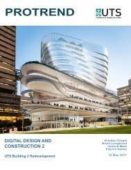
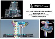
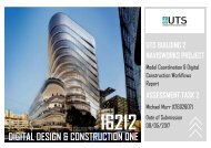
Digital Design and Construction 2<br />
16470<br />
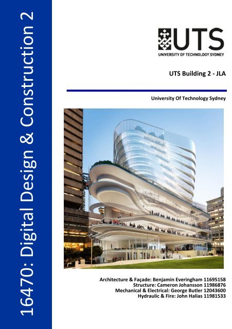
16470: Digital Design & Construction 2<br />
UTS Building 2 - <strong>JLA</strong><br />
University Of Technology Sydney<br />
Architecture & Façade: Benjamin Everingham 11695158<br />
Structure: Cameron Johansson 11986876<br />
Mechanical & Electrical: George Butler 12043600<br />
Hydraulic & Fire: John Halias 11981533
1.0 Description of Building Profile<br />
1.1 Description of the Building<br />
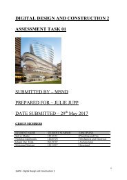
UTS Building 2 is a unique and intricately designed building that represents the first phase of<br />
the UTS City Campus Master Plan. The building, designed by Francis-Jones Morehan Thorp,<br />
has a striking glass encased podium on levels 3-7, with a further 9 levels above this with a<br />
glazed curtain wall facade that twists as the building progresses up. The end result will be a<br />
fascinating and impressive display of modern Architecture and construction and will<br />
undoubtedly place UTS Campus at the forefront of Australian Universities.<br />
Address<br />
Project Cost<br />
Project Duration<br />
Architect<br />
Main Contractor<br />
BUILDING 2 – UTS CENTRAL PROJECT DETAILS<br />
15 Broadway<br />
$278 Million<br />
29 Months<br />
FJMT<br />
Richard Crookes Constructions<br />
1.2 Purpose of the Building<br />
The end purpose of the building is first and foremost to enhance students experience at UTS.<br />
The building will also support UTS long-term strategic plan of growing in research while<br />
maintaining a positive contribution to the urban quality of the precinct and surrounding area.<br />
The building will serve as a new state of the art library, with student services hub, collaborative<br />
learning spaces, and student common areas all within the buildings confines.<br />
1.3 Scope<br />
The scope of works for Building 2 will first involve demolition of the existing building during<br />
the ‘quiet period’ beginning in November 2016. After demolition is complete, minor<br />
groundwork’s will be carried out and the buildings footings will be placed. It is important<br />
during demolition and groundwork’s that the existing services below the building are<br />
maintained for future use.<br />
After this is complete, work will commence on the structure, beginning with the FRP of ground<br />
floor slab with columns and structural steel to follow. This process will continue level by level<br />
up the building, with sequenced suspended slabs poured on top of the load bearing columns<br />
beneath and columns being poured in sequences after that. The glazed curtain wall facade<br />
will follow the structure up the building, with aluminium mullions installed first, followed by<br />
glazing and cladding. The façade installation will be complete simultaneously with the<br />
buildings structure, with electrical, mechanical, hydraulic, fire and security services to be<br />
roughed in keeping pace with the structure.<br />
Wall & ceiling linings and partitions will then be installed progressively up the building, all<br />
floor, wall and ceiling finishes and fit off of all services will be carried out and joinery will be<br />
fabricated and installed. Vertical transportation will be installed once the structure is<br />
complete. External landscaping works will then be completed to round out the project.<br />
4
1.4 Construction Methods<br />
Construction methods of note that will be utilised on Building 2 are as follows:<br />
<br />
<br />
<br />
<br />
<br />
<br />
<br />
<br />
Demolition of existing building while maintaining existing underground services for<br />
future use, and creating minimal public disturbance<br />
Scaffold working down the building with demolition<br />
Sequenced concrete pours with post-tensioned concrete slabs<br />
Aluminium framed glazed curtain wall facade with Low-e glazing<br />
Solid concrete core lift shaft<br />
Reinforced prefabricated fire stairs<br />
LED lighting throughout the building<br />
Mechanical ventilation throughout the building<br />
2.0 Description of Model Profiles<br />
2.1 Description of Architectural Model and Discrepancies<br />
The UTS Building 2 Architectural model is simplistic but still rather impressive, consisting of<br />
basic walls, floors, and ceilings, aluminium framed solid core doors, and joinery, all designed<br />
to suit the building's intricate structure and shape.<br />
During the process of implementing the Richard Crookes contract programme into Navisworks<br />
and creating a timeline simulation, it became evident that there are several discrepancies in<br />
the model.<br />
ARCHITECTURAL MODEL DISCREPANCIES<br />
The first and most notable discrepancy was the<br />
ceilings throughout the building not being allocated<br />
to a level as illustrated below. This made it quite<br />
challenging to create search sets for each level and<br />
meant that I could not use the same searches as I had<br />
used for other elements of the model. Instead I was<br />
required to click on each individual element of the<br />
ceiling for each level, create a search set using the ID<br />
of that element and then combine all of the search<br />
sets that I had created for that level.<br />
5
Level 15 Ceiling<br />
Another element of the Architectural model that had<br />
‘No Level’ assigned to it was the Bulkheads<br />
throughout the building. The bulkheads were also<br />
broken up into small sections for each level, as<br />
illustrated in the screen capture below. A<br />
construction programme will not normally be broken<br />
to the level of detail where portions of a levels<br />
bulkhead allocated to separate activity lines. This is<br />
also not realistic for a timeliner simulation.<br />
Instead of creating individual search sets for each<br />
levels bulk heads, I created just one search set for the<br />
entire buildings bulkheads and allocated this set to an<br />
activity that would show up towards the end of my<br />
simulation so it would not look out of place.<br />
Another discrepancy that I noticed in the model was<br />
that the plasterboard walls on various levels protrude<br />
straight through the ceilings and services space.<br />
Typically, plasterboard walls will run from the floor<br />
level to the bottom of the ceiling. This is illustrated<br />
below.<br />
6
On levels 13 & 14 of the model there are timber slats<br />
protruding from the bulkhead, however each piece of<br />
timber was separate, which again would have meant<br />
creating individual search sets for each slat and<br />
merging them for each level. Instead, I created one<br />
search set that captured all of the timber slats for<br />
both levels and assigned them to level 14 so that they<br />
would fit into my simulation smoothly.<br />
Another discrepancy in the Architectural model was<br />
the rooms on each level being having individual<br />
properties. This is not practical, as the layout of the<br />
walls, floors and ceilings will automatically create<br />
rooms according to their location. For the purpose of<br />
the timeline simulation, each of these rooms were<br />
allocated to the internal walls search sets.<br />
2.2 Description of Facade Model and Discrepancies<br />
The facade model is fascinating, with the glazed curtain wall wrapping around the buildings<br />
structure that twists from level 8 to the roof. This curtain wall system is supported by<br />
aluminium millions and has bronze metal clad floor plates. Unlike the Architectural model, the<br />
Façade model had very few discrepancies, and no issues with elements having no level<br />
assigned to them.<br />
For the purpose of creating a timeline simulation, there were some minor issues with the<br />
model such as each of the individual mullions on each level being separated. Again, it is not<br />
realistic in a construction programme to have each mullion separated into separate activities.<br />
Instead, I created a search set that captured all of the mullions for each level.<br />
7
FAÇADE MODEL DISCREPANCIES<br />
Individual Mullions<br />
As was the case with the mullions for each level,<br />
the Curtain Wall Glazing was split up into<br />
sections for each level. This is actually quite<br />
realistic, as only portions of a levels façade will<br />
be installed each day. However, for the purpose<br />
of creating a timeliner simulation it was far more<br />
practical to create a single search set that<br />
captures the curtain wall glazing for each level.<br />
This was also the case with the bronze metal<br />
cladding on each level, where it was split up into<br />
individual pieces. Again, I created a search set for<br />
each level that captured all of the cladding.<br />
8
2.3 Description of Structural Model and Discrepancies<br />
The structural model forms the foundation for the model, with all adjoining disciplines<br />
forming around the structural model. The model includes all structural elements for the<br />
building, which consists of both structural concrete and structural steel throughout. The<br />
elements that form the basis of the structural model (levels 8-18) include:<br />
<br />
<br />
<br />
<br />
<br />
<br />
<br />
<br />
<br />
Reinforced concrete beams<br />
Reinforced concrete slabs<br />
Reinforced concrete core walls<br />
Reinforced concrete blade walls<br />
Reinforced concrete fire stairs<br />
Reinforced concrete columns<br />
Horizontal structural steel<br />
Vertical structural steel<br />
Steel plates<br />
Upon commencement of the assessment task it became clear that there were a number of<br />
discrepancies in the structural model. These discrepancies were a result of two things, the<br />
first being the overlay between difference discrepancies, and the second being that the model<br />
had minor defects within itself.<br />
STRUCTURAL MODEL DISCREPANCIES<br />
Throughout the structural model is the inclusion of fire<br />
doors. These fire doors should be included in the<br />
Architectural model - clearly identifying one of the<br />
discrepancies in this structural model.<br />
From levels 10 to 16 there is the inclusion of a half-height<br />
blade wall that forms a part of the structural model.<br />
During the establishment of the search-sets for this item<br />
it became clear there was some minor defects within the<br />
element. A number of the blade walls were made up of a<br />
number of components, meaning that a detailed ‘Item’<br />
search-set needed to be created to ensure that all<br />
components for this item were included.<br />
9
The structural model had the inclusion of a number of<br />
structural steel plates. It is assume that these plates form<br />
a component for internal staircases - which are part of the<br />
architectural model. These items have been raised as a<br />
discrepancy within the structural model and will be<br />
included in the architectural discipline in the final<br />
federated submission.<br />
When reviewing the structural steel components for the<br />
roof level it was identified that a number of the elements<br />
show a disconnect. This is likely to be a result of the other<br />
disciplines being hidden from the structural model.<br />
The final discrepancies discovered during the model<br />
analysis was the identification of fire stairs on level 7 as<br />
listed as a level 8 component. This meant that when a<br />
search set was produced for the stairs on level 8, the stairs<br />
that were actually located on level 7 were also included.<br />
This is a minor discrepancy within the elemental profiling.<br />
10
2.4 Description of Mechanical & Electrical Model and Discrepancies<br />
RCC have created highly detailed representations of the electrical and mechanical services<br />
within their NAVIS works model. For the electrical services the model identifies the power<br />
supply, data, lighting and security. More specifically, the model breaks down systems into the<br />
following elements; Cable Trays, Cable Tray Fittings, Data Devices, Electrical Equipment and<br />
Security Devices. In terms of, mechanical services the model identifies the following systems;<br />
Heating, Cooling, Humidifying, Dehumidifying, Cleaning, Ventilation and Air movement. These<br />
are further broken down into elements including Ducts, Duct Fittings, Duct Accessories,<br />
Mechanical Equipment, Pipes, Pipes and Fittings.<br />
Whilst there were obvious clashes and discrepancies in the model a sufficient programmed<br />
simulation could still be developed. The five major components of these two disciplines that<br />
RCC have decided to break the model elements down into include the following:<br />
1. Electrical Equipment<br />
2. Cable Trays<br />
3. Supply Air<br />
4. Return Air<br />
5. Mechanical Ceiling Fittings<br />
Discrepancies<br />
Having interrogated the model and appended disciplines a number of discrepancies were<br />
identified. These discrepancies can be categorised into four general groups including; element<br />
clashes with other disciplines in the model, elements without an allocated level, elements<br />
appearing over multiple levels and elements not included in the model. In order to ensure the<br />
simulation showed the correct logic individual search sets were created for each discrepancy<br />
group. These additional search sets included the following:<br />
‣ Install Security Devices<br />
‣ Install Data Devices<br />
‣ Install Exhaust Air<br />
‣ Vertical Cable Trays<br />
‣ Vertical Exhaust Ducts<br />
ELEMENTS WITHOUT A LEVEL ALLOCATION<br />
Vertical Cable Trays without an allocated level. A separate<br />
search set was created for these items and programmed<br />
so that they appeared at the end of the simulation.<br />
11
There were a number of various items such as cable tray<br />
fittings and duct fittings particularly in the levels below<br />
level 8 that had no defined level attached to them. For the<br />
purpose of the simulation the majority of these were<br />
hidden.<br />
ELEMENTS APPEARING OVER MULTIPLE LEVELS<br />
Vertical Exhaust Duct connected to level 8 that travels across<br />
multiple levels. Initially an animation was created so that<br />
they gradually appeared with each level however upon<br />
exporting the file the program constantly crashed.<br />
Consequently, these ducts were programmed so that they<br />
appeared at the end of the simulation along with the duct<br />
insulation.<br />
Vertical Cable Tray connected to level 8 that travels across<br />
multiple levels<br />
12
Vertical Exhaust Duct connected to level 9 that travels across<br />
multiple levels<br />
Vertical Exhaust Duct connected to level 10 that travels<br />
across multiple floors<br />
Vertical Exhaust Duct connected to level 17/Roof that travels<br />
across multiple levels<br />
Vertical Supply Air duct connected to level 17/Roof that<br />
travels across multiple levels<br />
13
ELEMENT CLASHES WITH OTHER DISCIPLINES IN THE MODEL<br />
Supply air and return air ducting on levels 7, 8 & 10<br />
currently clashes with the architectural model. The<br />
ducting protrudes from the building through the<br />
facade<br />
Throughout the project there were a number of<br />
instances were cable trays clashed with mechanical<br />
ducting. Typically in most cases these issues could<br />
easily be resolved during construction.<br />
ELEMENTS NOT INCLUDED IN THE MODEL<br />
Elements such as the mechanical air handling units<br />
(dark blue elements in image) and grilles were not<br />
included in the mechanical model and therefore did<br />
not appear. Consequently these items were<br />
excluded from the simulation and program as they<br />
could not be successfully linked<br />
14
2.5 Description of Hydraulic & Fire Model and Discrepancies<br />
Fire:<br />
The fire model (pictured below) of the building incorporates a wet & dry fire service system<br />
easily distinguished in the selection tree feature of Navisworks. The elements within the fire<br />
services trade can then be separated under three main categories:<br />
- Installation of fire services - Fire pipe fittings & fire pipes.<br />
- Fit off fire services - Cable trays, centre lines & cable tray fittings.<br />
- Fire service equipment - Sprinklers & fire alarm devices<br />
Hydraulic – Pressure:<br />
The hydraulic model (pictured below) is made up of a combination between the hydraulic<br />
pressure and hydraulic drainage models. The Hydraulic Pressure System encompasses the<br />
pipes and pipe fittings which provide water with pressure to the fit off services (sprinklers) to<br />
each level. In addition to this, there are Hydraulic Pressure System fixtures which are only<br />
found in the model on Level 17 – the 87500L water tank and a water pump.<br />
15
Hydraulic – Drainage:<br />
The Hydraulic drainage system comprises of pipe fittings, pipes and plumbing fixtures.<br />
Although the element names of the drainage model are quite similar to the pressure and fire<br />
model, the differences can be found in the detail, showing that the pipes and pipe fittings in<br />
the drainage model encapsulate all the PVC piping, pipe fittings and recessed wall tundishes<br />
used for sanitary drainage throughout the building.<br />
HYDRAULIC & FIRE DISCREPANCIES<br />
The fire services on Levels 8-10. The sprinklers<br />
(blue) do not seem to be attached to any of the<br />
fire pipes or pipe fittings and hence would not<br />
have any water supplied to them.<br />
The water tank and water pump on the roof<br />
level. Not only are they not connected to each<br />
other but they have no pipes or piping systems<br />
connecting to them.<br />
16
A single cable tray from Level 8 and a single fire<br />
pipe from Level 17 in the Fire Services model<br />
travel all the way up to L17 (for the L8<br />
discrepancy) and all the way down to L8 (for<br />
the L17 discrepancy).<br />
The L8 fire pipe was hidden from view in the<br />
static simulation of the model to make it more<br />
aesthetically pleasing.<br />
Level 16 Hydraulic Pressure Services has picked<br />
up pipes and pipe fittings travelling all the way<br />
down to Level 8.<br />
There are two issues with Hydraulic Drainage<br />
Services to level 8.<br />
1. There are level 8 PVC pipe’s connecting<br />
down to the levels below Level 8.<br />
2. There are random PVC pipes up near Level<br />
15 which are part of the Level 8 Hydraulic<br />
set.<br />
This is an important discrepancy because in the<br />
simulations the random pipes at the top of the<br />
model were not hidden from the beginning and<br />
appear throughout the entirety of the videos.<br />
Level 8 sprinkler clashing with a level 9 PVC<br />
Drainage pipe. Not only does this show two<br />
items from separate models clashing but they<br />
are not even on the same level. One of many<br />
similar clashes within the model.<br />
17
3.0 Description of Site and Client Profile<br />
3.1 Location and Boundary of Site<br />
UTS Building 2 is located at 15 Broadway next to Building 1, the Tower Building, fronting onto<br />
Broadway. The building is adjacent to Jones Street with UTS buildings 10 and 11 across the<br />
street. This is illustrated on the site plan below.<br />
The site will have permanent hoarding erected around the perimeter, running along<br />
Broadway, adjacent to Building 11 and onto Jones Street, continuing along the rear of the site<br />
in front of UTS Building 7 and enclosing the site along Building 1.<br />
3.2 Vehicular Traffic and Pedestrian Flows<br />
Located in the heart of Broadway, UTS Building 2 is surrounded by heavy vehicular and<br />
pedestrian traffic in peak hours, particularly in the morning between 8-10AM with students<br />
arriving to university and commuters travelling to work and in the afternoon between 4-6PM<br />
with students departing university and commuters making their way home from work. Traffic<br />
is less intense outside of these hours, however there is still a steady flow of pedestrians<br />
throughout the day with students travelling throughout the university campus.<br />
This level of traffic will also fluctuate according to the time of year, where during university<br />
holidays in July and from November to March the pedestrian traffic will be significantly<br />
reduced. Vehicular traffic will also reduce in the summer months, as this is a common holiday<br />
period. Both pedestrian and vehicular traffic is significantly reduced on weekends.<br />
18
It is vital for UTS to maintain pedestrian access along Broadway as this is a main thoroughfare<br />
for students to travel from building to building. In order to allow for this, type B hoarding will<br />
be erected along the Broadway side of the site and will remain for the duration of<br />
construction.<br />
3.3 Site Specific & Logistics Details<br />
The site-specific construction hours for UTS Building 2 are as follows:<br />
Monday to Friday: 7am to 5pm<br />
Saturday: No work<br />
Sunday: No work<br />
An application must be submitted and a fee paid for work to occur outside of these hours.<br />
Deliveries to the site are also very restricted; it is not feasible to be taking deliveries from<br />
Broadway as the effect on the traffic would be too severe, meaning Jones Street is the only<br />
reasonable site entrance to be taking deliveries. Although Jones Street has very little vehicular<br />
traffic, the level of pedestrian traffic is quite high with students using this street to travel from<br />
buildings 10 and 11 to building 7 and the alumni area. This will require ongoing attention<br />
during construction to ensure deliveries are not endangering students or disrupting UTS<br />
operations.<br />
3.4 Client Operations and Constraints<br />
UTS has a responsibility to its students to provide a high level facility for them to learn and<br />
study, meaning disruptions to classes due to construction works are unacceptable. With this<br />
in mind, UTS have imposed several requirements around days where there can be restricted<br />
work or no work, such as student graduation days and formal examinations. Works that are<br />
particularly disruptive to UTS daily operations, such as demolition, are required to be carried<br />
out during student holidays.<br />
It is also critical that UTS be given at least 7 days’ notice of any disruptions or restrictions to<br />
building access as a result of construction works.<br />
4.0 Risk Analysis & Management Approach<br />
Traffic:<br />
4.1 Controlled Risks<br />
Traffic conditions are a major risk that particularly relevant to this building site. This is largely<br />
due to the location of the site in relation to Broadway and central station. In order to ensure<br />
that this risk is mitigated it will be crucial develop and implement a traffic management plan.<br />
This will be important to ensure that deliveries to site and site activities do not cause<br />
disturbances to the public. In the same way, monitoring of the traffic conditions and updated<br />
management plans will be important for RCC to ensure that traffic conditions do not<br />
19
jeopardise critical path activities such as concrete pours and deadlines. Establishing work<br />
zones on Jones Street to allow for deliveries and other activities will be an important aspect<br />
of the traffic management plan. In addition, signage and pre-delivery notifications for delivery<br />
routes will ensure efficiency. The use of traffic controller subcontractors also will assist with<br />
this process.<br />
Pedestrian traffic is another risk that must be closely controlled as there is constantly a high<br />
volume of people walking around most of which are UTS pupils. Hoardings along Broadway<br />
and Jones Street as well as signage will ultimately play a crucial role in diverting pedestrian<br />
traffic and ensuring that there is a safe environment around the site boundaries.<br />
Traffic Risk<br />
Traffic incident causing<br />
major disruptions to site<br />
activities<br />
Disruptions to local traffic<br />
caused by a backlog of site<br />
deliveries<br />
Pedestrian injuries caused<br />
by site activities<br />
Likely<br />
Hood<br />
Consequence<br />
Matrix<br />
Score<br />
Likely Major 8<br />
<br />
<br />
Management<br />
Critical path programme<br />
activities to occur outside of<br />
peak hour traffic<br />
Ensure constant traffic<br />
updates are made readily<br />
available to subcontractors<br />
and site personnel<br />
Likely Major 8 Implementation of Traffic<br />
Management Plan<br />
Hoardings around site<br />
Warning signage<br />
Unlikely Catastrophic 9<br />
Lower speed limits around<br />
site boundaries<br />
Material supply and availability:<br />
Sydney is currently experiencing a boom in construction activities which is subsequently<br />
placing a lot of pressure on material and labour suppliers. This ultimately poses a great risk to<br />
the project and needs to be managed effectively so as not to cause major delays. Early<br />
subcontractor lettings and material procurement will ultimately play a crucial role in this<br />
process allowing for long lead time items to be secured and labour resources managed.<br />
Ultimately, clear communication between RCC and their subcontractors and suppliers is what<br />
will enable this to happen.<br />
Labour and Material Risk<br />
Likely<br />
Hood<br />
Consequence<br />
Matrix<br />
Score<br />
Management Approach<br />
Ensuring a constant supply<br />
of the required labour and<br />
materials<br />
Likely Major 8<br />
<br />
Clear dialogue and<br />
forecasting will mitigate this<br />
risk<br />
20
Delay in material supply<br />
Long lead time items i.e.<br />
facade<br />
Unlikely Major 6<br />
Unlikely Major 6<br />
<br />
<br />
<br />
<br />
Clear dialogue between<br />
subcontractors to ensure that<br />
they are managing their<br />
suppliers<br />
The same applies to supply<br />
agreements set up between<br />
RCC and the suppliers directly<br />
Early procurement and shop<br />
drawing approval<br />
Clear communication<br />
between RCC and<br />
subcontractor<br />
Communication/Reporting<br />
Breakdowns in communication are a major risk to construction projects that can have major<br />
impacts on programme, safety, quality, cost and efficiency. Coordination amongst the many<br />
stakeholders and parties involved in the process is key.<br />
In order to ensure that this risk is controlled a number of measures can be implemented by<br />
RCC including:<br />
Integration of a Building Information Modelling Systems<br />
Regular forecasting and report generation from data extracted from the BIM such as<br />
safety incidents and productivity of site activities<br />
Scheduled toolbox and site meetings<br />
Regular PCG meetings with the University and shareholders<br />
Open dialogue with the UTS student and staff faculty<br />
Standards and Legislations/safety<br />
A number of techniques and procedures can be implemented in order to manage risks<br />
associated with legislation, standards and safety.<br />
The key governing legislation includes the following:<br />
Safe Work Australia Code of Practice<br />
National Code of Construction (BCA)<br />
Work Health and Safety Regulations 2011<br />
Standards,<br />
Legislation and<br />
Safety risks<br />
Injuries to site<br />
personnel<br />
Likely<br />
Hood<br />
Consequence<br />
Matrix<br />
Score<br />
Unlikely Catastrophic 9<br />
<br />
Management Approach<br />
Ensuring there is a safe building<br />
environment, edge protection,<br />
regular safety talks, signage, PPE<br />
regulation, regular equipment<br />
inspections<br />
21
Injuries to members<br />
of the public<br />
Shutdown of site<br />
activities due to noncompliance<br />
with<br />
legislation<br />
Non-compliance with<br />
NCC and BCA<br />
standards<br />
Unlikely Catastrophic 9<br />
Unlikely Major 6<br />
Unlikely Major 6<br />
Suitable hoardings, signage,<br />
safety officers, site personnel<br />
directing traffic, exclusion zones<br />
Ensuring high risk works take<br />
place outside of peak hours<br />
Regular safety audits<br />
CFMEU communication<br />
<br />
<br />
Regular inspections by architect<br />
and Private Certifying Authority.<br />
Use top consultants for design to<br />
ensure it complies on paper first<br />
Client operations and constraints<br />
Ensuring minimal disturbances to the UTS campus and activities is a crucial component of the<br />
project and risk that needs to be controlled.<br />
<br />
<br />
<br />
Noise and vibration control will need to be established so as not to disturb UTS<br />
lectures and activities<br />
Dust suppression is critical to ensure there is a safe and clean environment on the<br />
nearby campuses<br />
Effective programming and consideration of peak university times and activities needs<br />
to be incorporated into the projects strategic planning<br />
Risk of Contract Variations<br />
Variations pose a risk to the client as they are liable for costs incurred by changes in the<br />
construction. Early design resolution will be key to mitigating the likelihood of major variations<br />
arising and an open dialogue between RCC and UTS will facilitate this. Carefully and fairly<br />
writing risk into the contract agreement will also ensure that the project runs smoothly.<br />
Time Based Risks:<br />
Effective time management will ultimately determine the success of the UTS project. There is<br />
a lot of overlap between the various controlled risk strategies and the one that is particular<br />
important to managing time is communication. The use of BIM will ensure that all parties are<br />
constantly provided with the latest information and documentation to enable them to<br />
program their works.<br />
22
Programme Risks Likely Hood Consequence<br />
Matrix<br />
Score<br />
Scope Creep Unlikely Catastrophic 9<br />
Liquidated damages for<br />
RCC<br />
Unlikely Moderate 6<br />
Long Lead time items Unlikely Major 8<br />
Management Approach<br />
Cost Plus contract may lead to<br />
scope creep<br />
Early design finalisation<br />
required<br />
Open dialogue with client<br />
Forecasting<br />
Subcontractor meetings<br />
Early engagement of<br />
subcontractors, early order<br />
and shop drawing approvals<br />
Weather<br />
4.2 Uncontrolled Risks<br />
With an estimated building time of approximately two years, it is certain that during the<br />
construction phase of UTS Building 2, workers on site will be faced with some sort of<br />
inclement or abnormal weather conditions. Whether it be extreme heat, storms, high winds<br />
or torrential rain these conditions will not only affect the duration of the project but more<br />
importantly, would have a significant impact on the safety of workers involved on the<br />
construction site. With the safety of workers being a top priority on site, there are a number<br />
of measures and precautions which can be taken to minimise the financial and physical<br />
effects of these unforeseen circumstances.<br />
For example:<br />
<br />
<br />
<br />
The appropriate use of the technology would allow RCC construction managers to<br />
make knowledgeable decisions about any potential hazardous or poor weather<br />
conditions. This would ensure that project managers can schedule the appropriate<br />
time into their programs for potential delays and stoppages. Not only would this<br />
reduce the risk of injury on site (when the weather struck) but a better planned<br />
program would ensure the time lost due to delays was minimal.<br />
To keep employees safe, RCC construction managers are to ensure that there are no<br />
works carried out when there are extremely high wind conditions, heavy rainfall or<br />
extremely high temperatures.<br />
Allowance for delay costs in contingencies and extension of time clauses would also<br />
allow RCC construction managers to be able ensure the financial consequences of<br />
inclement weather conditions are minimised.<br />
23
Industrial Action<br />
With the Australian construction industry being one of the most litigious and disputable in<br />
the world, it is important to take into account the effects industrial action could have during<br />
the construction of UTS Building 2. Industrial action including strikes or stoppages of work<br />
could easily occur if employees begin to refuse to do work because they believe they are<br />
being unfairly treated or their health and safety is at risk. This would not only become a<br />
nuisance for RCC but it would delay construction and lead to potential significant delays in<br />
the project which could incur significant unwanted costs. To minimise the chance of<br />
industrial action occurring during construction, RCC should:<br />
<br />
<br />
Maintain constant communication with employees and union representatives to<br />
ensure all relationships are strong and all parties are able to voice any concerns<br />
about each other if need be.<br />
Build a strong and positive culture around the workplace and on the construction<br />
site. Creating an environment where all staff and workers feel that they are<br />
accepted, safe and respected will not only lead to workplace where work is done at<br />
an optimum efficiency but would ensure that individuals are content with their job<br />
and are much less likely to take industrial action against RCC.<br />
5.0 Proposed site layout<br />
The proposed site produces a number of potential issues when looking at site establishment.<br />
When looking at the final site establishment it is important to consider all site constraints and<br />
the site specific requirements including; access, materials handling, site accommodation,<br />
perimeter boundary, DA requirements and so forth. These items are explored below in detail.<br />
5.1 Site Perimeter & Fencing<br />
The requirements for site hoardings and fencing are largely dependent on the live<br />
environment that the surrounding neighbours present. As a university campus there will be<br />
continual traffic and people management, which will form the basis of hoarding and fencing<br />
selection for the project. Taking into consideration the adjoining roads and building, there will<br />
be a requirement for two types of hoarding. The two hoarding types will be Class A acoustic<br />
hoarding and a Class B hoarding.<br />
5.1.1 Class A Acoustic Hoarding<br />
The live environment presented by the university campus will ultimately call on the use of an<br />
acoustic Class A hoarding for majority of the site perimeter. This hoarding type will provide an<br />
ideal barrier between the site and the surrounding operational buildings. The hoarding will<br />
also provide acoustic dampening during noisy operations, reducing disruptions to the<br />
neighbouring sites.<br />
24
5.1.2 Class B Hoarding<br />
The site enclosed by three (3) operation roads, one of which is the ever busy Broadway. This<br />
will present the requirement for a Class B hoarding along the perimeter on the Broadway side.<br />
This will be required to provide pedestrian access during the construction phase and provide<br />
safe access and egress to the surrounding areas for all.<br />
5.2 Cranage and Materials Handling<br />
The site provides the requirement for a crane to be used during the construction phase. When<br />
looking at the site constraints and close proximity to surround buildings, it is evident that a<br />
Luffing Crane will need to be used. This will suit the radial restrictions presented by the nearby<br />
buildings to the site and reduce risks during construction. The recommended crane size is a<br />
35m Luffing Crane which will have a lifting capacity of 16 tonne.<br />
The crane will be located as shown in the below image. This will provide the best solution for<br />
materials handling on site - allowing vertical materials handling during construction phase.<br />
This will allow for materials handling on a large scale and will allow the contractor to relocate<br />
materials as required. The crane will be situated nearby the driveway/loading area for the<br />
site, ensuring that there is reduced risk when large deliveries are made and require materials<br />
handling. This is shown below.<br />
25
All site deliveries will be coordinated via Jones St using the site gate entry as shown above.<br />
This will reduce the risk for traffic management on Broadway, which would require extensive<br />
traffic management if it was to be used. Deliveries through Jones St will also suit the site<br />
layout, allowing trucks to drive directly into the site from the rear. Traffic management and<br />
materials handling are highlighted on the satellite image below.<br />
5.3 Site Facilities<br />
The site will require a number of site facilities to account for people management on site. The<br />
general requirements for the site will be a site office, bathroom and amenities, lunch room<br />
and change rooms. Given the site constraints that are present, an effective site layout will be<br />
required to ensure that all these items can fit within the site boundaries. It is suggested that<br />
a stacking methodology be put in place for the site facilities to allow the best use of space on<br />
site. An example of provided below.<br />
26
The layout of the site facilities has been taken into consideration the cranage and materials<br />
handling requirements, meaning that all site facilities will be located on the Western side. This<br />
will reduce risk of site access issues during periods of large deliveries and high site activity. A<br />
detailed outlook on the site facilities layout is shown on the site establishment plan on the<br />
following page.<br />
5.4 DA Approved Hours & Site Layout<br />
Monday - Friday: 7:00am - 5:30pm<br />
Saturday: 7:00am - 5:00pm<br />
Sundays and Public Holidays: No site activity/noise permitted<br />
27
6.0 Analysis & Implementation of RCC Contract Programme<br />
6.1 Architectural & Façade<br />
6.1.1 Deficiencies in the RCC Contract Programme<br />
The Richard Crookes Constructions programme for Architecture was quite accurate and had<br />
sufficient detail to create an accurate timeline simulation of the project. For construction<br />
purposes it is worth noting that the programme could have been broken down into more<br />
detail, for example floor finishes could have several sub-tasks such as tile finishes, carpet<br />
finishes, stone and vinyl.<br />
Although there was a lack of breakdown for activities such as floor finishes and internal walls,<br />
the durations assigned to these tasks were very accurate.<br />
Original Richard Crookes Contract Programme<br />
Contrastingly, the original façade programme had only one task for the whole façade of each<br />
level. This is unrealistic for both a timeline simulation and construction. In order to depict a<br />
more realistic programme, several sub tasks were added to the façade installation.<br />
The screen capture below shows that additional sub tasks that were added to the façade<br />
installation, where the mullions are installed separately, followed by the glazing and then the<br />
bronze metal cladding.<br />
28
Another discrepancy in the original programme was the fact that there was no tasks for Level<br />
18/Roof, however as the time liner screen shot below illustrates, the façade of the building<br />
extends onto the roof and overhangs the plant on the roof.<br />
29
6.1.2 Prescribed & Additional Search Sets Implemented<br />
The search set folder structure for each level of the Architectural and Façade models is very<br />
comprehensive and fluid throughout the building, with the same folder structure for all levels.<br />
Both disciplines are broken down by level, with each of the subtasks in the level folders. This<br />
structure was very easy to follow and made the process of duplicating search sets for each<br />
level very efficient.<br />
Architectural & Façade Search Set Folder Structure<br />
30
The screen capture below shows the search sets that were created for the level 10 ceiling. As<br />
mentioned previously, this was one of the most challenging aspects of the Architectural model<br />
and required many additional search sets to be created.<br />
In contrast to the level 10 ceiling search set, a much more simple approach was taken to the<br />
bulkhead search sets, as illustrated below. The one search set that was created captured all<br />
of the bulkheads in the model.<br />
31
6.1.3 Appearance Profiling<br />
The appearance profiling colour selection process was quite extensive for the Architectural<br />
and Façade models. In order to create an effective timeline simulation that highlights each of<br />
the aspects of the building, it is crucial to select appropriate colours and set the transparency<br />
for each item to the most optimal setting.<br />
The process of selecting colours for each element mainly involved trial and error. The table<br />
below show the colours that were decided upon and the level of transparency that was<br />
allocated to each item. The façade has quite a high level of transparency, as this allows you to<br />
view the fit out of the building during the simulation. The floors and ceilings also have a<br />
relatively high transparency as this allows you to view the floors below during the simulation.<br />
Architectural/Façade Element<br />
Colour/Nominated Transparency<br />
Architectural Elements<br />
Walls<br />
Untouched<br />
Ceilings Red, 55%<br />
Floors Grey, 50%<br />
Façade Elements<br />
All facade Khaki, 75%<br />
Architectural & Façade Appearance Profiling Table<br />
6.1.4 Illustration of Sequencing<br />
Install Level 8 Mullions<br />
32
Install Level 8 Glazing<br />
Install Walls and Hang Doors<br />
Install Floor Finishes and hang<br />
ceilings. Ceilings are shown in<br />
red and floor finishes are<br />
shown in grey.<br />
Levels 9-17 are all typical of Level 8.<br />
33
6.2 Structural<br />
6.2.1 Deficiencies in RCC Contract Programme<br />
When presented with the structural model and original RCC Contract, it was clear that<br />
additional task items needed to be added to the programme to account for all structural<br />
elements. The original RCC Contract Programme detailed each level as shown below:<br />
While this formed the basis of what was required for the project programme, there were<br />
additional items that needed to be included to account for all structural elements. The<br />
additional items that were to be added included the requirement for four (4) slab pours on<br />
level 8, additional tasks for fire stairs and inclusion of structural steel. In addition to this, it<br />
was identified that a number of the tasks had unrealistic timeframes for the tasks. This<br />
resulted in the redrafting of the work breakdown structure and their applicable time frames.<br />
An example of the updated work breakdown structure is shown below.<br />
The final work breakdown structure above accounts for the particular structural model<br />
breakdown and ensured that the animation was developed to a suitable level. The separation<br />
of the fire stairs from the core allowed for a realistic animation, ensuring that the two items<br />
were completed separately. Likewise with the addition of structural steel, which was not<br />
originally accounted for.<br />
34
6.2.2 Prescribed and Additional Search Sets<br />
Following the update to the RCC Programme it then allowed for an improved level of detail to<br />
be applied to the Navisworks search sets. The search sets for the structural model were<br />
developed on a level to level basis, with a level specific analysis being applied to each search<br />
set. This saw task specific inclusions and exclusions being applied throughout the sets to<br />
account for the breakdown requirements and various discrepancies. The general basis for<br />
forming my level by level search sets is depicted in the image for the level 8 search sets.<br />
The naming conventions were duplicated for each level to ensure formality throughout. This<br />
provided greater ease when adapting the programme with the additional search sets for the<br />
project.<br />
6.2.2.1 Separating Concrete Pours<br />
The breakdown for level 8 provides and overview to the number and type of search sets that<br />
were created for the final submission. This includes all additional tasks that were added to the<br />
programme and identifies where the breakdown was for the number of concrete pours.<br />
These search sets were developed to ensure that the specific elements were connected to the<br />
work breakdown structure. An example of how the inclusions and exclusions were developed<br />
is shown below.<br />
35
This is example of how the separation for slab pours was created for the model. These search<br />
sets were then duplicated for each level and then applied to the specific level. Level 8 was the<br />
only level that required four separate slab pours.<br />
6.2.2.2 Itemised Blade Walls<br />
In addition to the separate pours, another key example of additional level specific search sets<br />
is shown through the various blade walls from level 10-16. Throughout these levels there were<br />
various defects involved with the design development of the concrete blade walls. To<br />
overcome the defects, a search set was created for the core, excluding the property details<br />
for these blade walls. From this, an additional search set was created for the blade walls with<br />
a corresponding programme task.<br />
Work Breakdown_Level 11<br />
Search Set_FRP_Core_11<br />
Search Set_FRP_Half Height Wall_11<br />
36
By isolating these items under separate search sets it not only allowed for the defects to be<br />
addressed in the blade walls, but it also ensured the blade walls were animated correctly.<br />
These items were originally included in FRP_Core_11, meaning that they were poured before<br />
a slab appeared. This was identified when the first Timeliner was produced. This was<br />
addressed and now all blade walls are programmed to be completed following the slabs.<br />
6.2.2.3 Structural Steel<br />
The original work breakdown made no allowance for structural steel inclusions. When this<br />
was added to the programme, a corresponding search sets was established. This was<br />
conducted for levels eight (8), seventeen (17) and eighteen (18). This separated all concrete<br />
and steel items within the structural model and was fundamental when producing the<br />
animation. An example of the applied search sets is shown below.<br />
37
6.2.3 Appearance Profiles<br />
The structural model was originally provided as a grey scale, providing little appear profiling<br />
for the model. As explained in class, colouring profiling for Structural models generally<br />
incorporates a grey themed appearance profiling. This allows little room for variation across<br />
the overall profiling for the model, however we endeavoured to produce a model that had<br />
varying scales of grey.<br />
The appearance profile applied to the structural model saw a breakdown as follows:<br />
Component<br />
Colour<br />
Concrete walls<br />
Slabs<br />
Concrete Columns<br />
Structural Steel<br />
By applying these four appearance profiles to the structural model it enhanced the visual<br />
appearance when simulating the model. The variance in the colours helps identify the various<br />
components that make up the structural discipline.<br />
6.2.4 Illustration of Sequencing<br />
The sequencing of the structural model forms a step by step process that becomes quite<br />
repetitive once the foundation is complete. Starting from level 8 the first stage is the<br />
construction of the lift and stair core, followed by the slabs, structural steel, blade walls and<br />
concrete columns. This process forms the basis of the model sequencing, which is then<br />
repeated on a level by level process. However, there are some changes applied to the final<br />
stages when finishing level 17 and 18, all of which will be explored below.<br />
Stage 1 - Form/Reo/Pour_Core_8<br />
38
Stage 2 - Pour_Stairs_8<br />
Stage 3 - Pour 1_Form/Reo/Pour Suspended Slab_8<br />
Stage 4- Pour 2_Form/Reo/Pour Suspended Slab_8<br />
39
Stage 5 - Pour 3_Form/Reo/Pour Suspended Slab_8<br />
Stage 6 - Pour 1_Form/Reo/Pour Suspended Slab_8 + MS Steel_Structural Steel<br />
Stage 7 - Pour 1_Vertical Elements (columns)_8<br />
40
Stage 8 - Pour 2_Vertical Elements (columns)_8<br />
This process was then repeated as the model progresses. However, there was a reduction in<br />
the amount of slab pours completed per level, with levels 9-16 only requiring two. Following<br />
the completion of level 16 there was slight changes in the sequencing to complete level 17<br />
and 18/Roof.<br />
Final Stages - Form/Re0/Pour_Core_17<br />
Final Stages - Pour 1_Form/Reo/Pour_Suspended Slab_17<br />
41
Final Stages - Pour 2_Form/Reo/Pour_Suspended Slab_17<br />
Final Stages - Vertical Steel_17<br />
Final Stages - Pour_Form/Reo/Pour Suspended Slab_18<br />
42
Final Stages - Form/Reo/Pour_Core_18<br />
Final Stages - MS Steel_18<br />
Final Stages - MS Steel_Roof<br />
43
Final Stages - Form/Reo/Pour_Slab_Roof<br />
6.3 Mechanical & Electrical<br />
6.3.1 Deficiencies in RCC Contract Programme<br />
Following an analysis of the RCC programme it became evident that there were a number of<br />
deficiencies relative to a lack of information. Consequently, the contract programme did not<br />
demonstrate a logical breakdown of the works. In order to provide an accurate programme<br />
and final simulation the original elements provided by RCC were broken down in detail and<br />
programme items were implemented. In the case of the electrical services the RCC<br />
programme allowed for cable tray installations and electrical equipment. An additional three<br />
categories were added including vertical cable trays, security devices and data devices.<br />
The mechanical programming was also fairly general and required additional category<br />
breakdowns. The RCC programme allowed for supply air, return air and mechanical ceiling<br />
fixtures. The additional categories that were created included exhaust air, vertical ducting and<br />
duct insulation. The lack of an exhaust air installation category was a major discrepancy in the<br />
programme as it constituted such a large proportion of the mechanical model consisting of<br />
toilet exhausts, kitchen exhausts, general exhausts and hazardous exhausts.<br />
Another discrepancy was the lack of phasing information connected to the mechanical and<br />
electrical components. As a result these large components could not be broken down in the<br />
simulation so as to show the gradual installation purpose. Instead bulk items such as the<br />
supply ductwork to the whole floor would appear.<br />
Furthermore, in completing this exercise the time allocations for the various elements were<br />
consolidated in order to show a logical progression of the installation works. Electrical<br />
equipment was installed first followed by the various ductwork types as shown in the below<br />
programme screenshot. The RCC programme did not break provide this logical sequencing.<br />
44
6.3.2 Prescribed & Additional Search Sets Implemented<br />
PRESCRIBED & ADDITIONAL SEARCH SETS:<br />
Security devices, data devices and<br />
exhaust air were added in order to<br />
further breakdown and logically format<br />
the simulation<br />
Level 9-17 are the same<br />
ADDITIONAL SEARCH SETS FOR ELEMENTS WITHOUT A DEFINED LEVEL<br />
Additional search sets were made in<br />
order to separate elements that<br />
travelled across numerous floors in the<br />
simulation. These consisted of exhaust<br />
air ducts, supply air ducts and horizontal<br />
cable trays<br />
45
6.3.3 Appearance Profiles<br />
APPLICATION OF DISCIPLINE SPECIFIC APPEARANCE PROFILES<br />
Install Electrical Equipment<br />
Install Security Devices<br />
Install Data Devices<br />
Install Cable Horizontal Trays<br />
Install Supply Air<br />
Install Return Air<br />
Install Exhaust Air<br />
Fit Off Mechanical Ceiling Fixtures<br />
Duct Insulation<br />
Shades of yellow were allocated to the electrical services and shades of orange with the<br />
exception of the blue for ducting insulation was used to represent the mechanical services.<br />
These were chosen in preparation for the federated model so as to minimise the possibility of<br />
colour clashes across disciplines.<br />
6.3.4 Illustration of Sequencing<br />
SEQUENCING OF WORK PACKAGES<br />
Level 8: Electrical equipment including data and<br />
security devices were installed first followed by<br />
the electrical cable trays. Once all the electrical<br />
equipment was all installed the supply air<br />
ductwork and return air ductwork was installed<br />
followed by the exhaust are and mechanical ceiling<br />
fixtures.<br />
46
Level 9: There was a distinct difference in the<br />
amount of ductwork between level 8 and 9. There<br />
was significantly less on level 9.<br />
Level 10: Levels 10 through to 16 follow the same<br />
installation process. Electrical equipment first<br />
followed by cable tray installation, supply<br />
ductwork, return ductwork, exhaust ductwork and<br />
mechanical ceiling fixtures.<br />
Level 17/Roof: The roof was an interesting level for<br />
the mechanical services. There was a lot of plant<br />
equipment located that had to be separated into<br />
individual search sets. An animation was created<br />
so as to have the vertical exhaust and supply air<br />
ducting however upon integrating the animation<br />
into the simulation and exporting the file the<br />
programme would constantly crash. For this<br />
reason these elements were time lined so as to<br />
appear at the end of the simulation along with the<br />
ducting insulation.<br />
47
Ductwork Insulation (all levels): Ductwork<br />
insulation was the final element that was<br />
programmed to appear in the simulation<br />
6.4 Hydraulic & Fire<br />
6.4.1 Deficiencies in the Construction Programme<br />
The original RCC Contract is simply split into five line items which on a very broad level<br />
encapsulate all of the works required to be carried out throughout each Level 8-17.<br />
Although there was a late programme update for the fire and hydraulic part of the model,<br />
RCC did well to link the activities to each other correctly and with the appropriate time<br />
allocations. The line items themselves lacked detail and on their own did not seem to<br />
highlight all the elements within each level. Further search sets need to be implemented<br />
to help increase the level of detail in the construction process and improve the logical flow<br />
of the simulation.<br />
48
The complications and discrepancies within the Hydraulic part of the program (Pressure<br />
Services, Horizontal Drainage and Vertical Drainage) which caused a number of items to<br />
run between certain levels when they shouldn’t have been made it difficult to separate the<br />
pipes during the simulation. So, after search sets were made, the dates of completion for<br />
some of these items were changed purely to suit the simulation, even though this process<br />
was not at all logical (see below).<br />
6.4.2 Prescribed & Additional Search Sets Implemented<br />
The amended programme was made to encompass all of the individual elements in the<br />
combined model but made sure to keep them in under their original line item task<br />
(coloured orange above) through the use of sub-tasks. The subtasks were grouped<br />
together under the original line item task and ensured that there was no substantial<br />
changes to the program and it was still effective and easy to follow.<br />
For instance, there were seven items which were included in the fire model. Individual<br />
search sets were made for each of these items for each level. In the programme, they were<br />
then included as a sub task under one of the two original line items- Install fire pipe_8 and<br />
Fit off Fire Services_8. This ensured that all fire items were picked up in the model and were<br />
able to be easily tracked in the programme and Navisworks file.<br />
49
The Hydraulic Pressure Services line item (third original task highlighted orange above)<br />
combined all of the items existent in the hydraulic pressure services model (pipes and pipe<br />
fittings as well as plumbing fixtures for level 17 only). Hence there was no need to add any<br />
additional subtasks for the pressure services.<br />
The drainage services had two original tasks- horizontal and vertical. The horizontal and<br />
vertical drainage pipes were separated by gradient- either equal to 0.00% gradient<br />
(horizontal) or not equal to 0.00%. The two other elements of the drainage model were<br />
given their own individual search set and were kept under the original Horizontal drainage<br />
task.<br />
6.4.3 Appearance Profiles<br />
Element of the Model<br />
Fire System<br />
Hydraulic Pressure System<br />
Hydraulic Drainage System<br />
Appearance Profile Colour<br />
The three modelling systems encompassed within the hydraulic and fire discipline have<br />
been divided into three colours (as depicted above). Simply approaching the colour<br />
scheme with only three colours made the model simulations very easy to follow and<br />
allowed the disciplines to be easily distinguished. Any more than three colours would<br />
have made the model too sophisticated and too colourful, making the elements within<br />
each system too difficult to separate from the rest of the model.<br />
50
6.4.4 Illustration of Sequencing<br />
Illustrations<br />
Descriptions<br />
The model simulation begins with the<br />
level 8 drainage system being laid in<br />
place. The level 8 steel fire pipes are then<br />
put in place shortly before the ceiling<br />
goes up.<br />
Once the ceiling has been installed, the fit<br />
off fire services for this level (sprinklers)<br />
are then installed. They are theoretically<br />
then connected to the water supply pipes<br />
but they are non-existent in the model.<br />
Level 9 then follows the same sequence<br />
as level 8 and is installed next (Installation<br />
of drainage Installation of fire pipe<br />
services Fit off fire services). In this<br />
level the steel galvanised pipes of the<br />
hydraulic pressure system become clear.<br />
51
As the simulation progresses, the same<br />
construction method applies to each<br />
level.<br />
Due to the discrepancy of the pipes in the<br />
pressure system, a scaling animation was<br />
used to gradually bring them into the<br />
model rather than having them sticking<br />
out of level 8 at the beginning of the<br />
simulation. These pipes can be seen<br />
coming into the model from the bottom<br />
of the screen.<br />
The simulation continues nicely, with the<br />
level 8 hydraulic pressure system<br />
elements gradually continuing to grow<br />
upwards through the building.<br />
By this stage, the scaling process of the<br />
level 8 hydraulic pressure services has just<br />
finished and the model is only about a<br />
month away from being complete.<br />
52
Day 249 of the program sees the level 8<br />
hydraulic vertical drainage pipes enter<br />
into the simulation.<br />
Although this does not fit chronologically<br />
into the program, the scaling animations<br />
were proving too difficult to perfect so it<br />
was decided that these elements should<br />
be brought into the program at this stage<br />
to prevent them being an eye sore<br />
throughout the simulation.<br />
The simulation finishes nicely with the<br />
hydraulic pressure fixtures coming into<br />
level 17. The model is completed with the<br />
fire piping to the roof of this level.<br />
53