


Create successful ePaper yourself
Turn your PDF publications into a flip-book with our unique Google optimized e-Paper software.
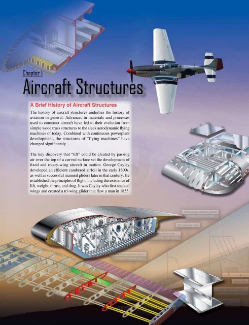
Chapter 1<br />
<strong>Aircraft</strong> <strong>Structures</strong><br />
A Brief History of <strong>Aircraft</strong> <strong>Structures</strong><br />
The history of aircraft structures underlies the history of<br />
aviation in general. Advances in materials and processes<br />
used to construct aircraft have led to their evolution from<br />
simple wood truss structures to the sleek aerodynamic flying<br />
machines of today. Combined with continuous powerplant<br />
development, the structures of “flying machines” have<br />
changed significantly.<br />
The key discovery that “lift” could be created by passing<br />
air over the top of a curved surface set the development of<br />
fixed and rotary-wing aircraft in motion. George Cayley<br />
developed an efficient cambered airfoil in the early 1800s,<br />
as well as successful manned gliders later in that century. He<br />
established the principles of flight, including the existence of<br />
lift, weight, thrust, and drag. It was Cayley who first stacked<br />
wings and created a tri-wing glider that flew a man in 1853.<br />
1-1
Earlier, Cayley studied the center of gravity of flying<br />
machines, as well as the effects of wing dihedral. Furthermore,<br />
he pioneered directional control of aircraft by including the<br />
earliest form of a rudder on his gliders. [Figure 1-1]<br />
In the late 1800s, Otto Lilienthal built upon Cayley’s<br />
discoveries. He manufactured and flew his own gliders<br />
on over 2,000 flights. His willow and cloth aircraft had<br />
wings designed from extensive study of the wings of birds.<br />
Lilienthal also made standard use of vertical and horizontal<br />
fins behind the wings and pilot station. Above all, Lilienthal<br />
proved that man could fly. [Figure 1-2]<br />
Octave Chanute, a retired railroad and bridge engineer,<br />
was active in aviation during the 1890s. [Figure 1-3] His<br />
interest was so great that, among other things, he published<br />
a definitive work called “Progress in Flying Machines.” This<br />
was the culmination of his effort to gather and study all the<br />
Figure 1-2. Master of gliding and wing study, Otto Lilienthal (top)<br />
and one of his more than 2,000 glider flights (bottom).<br />
information available on aviation. With the assistance of<br />
others, he built gliders similar to Lilienthal’s and then his<br />
own. In addition to his publication, Chanute advanced aircraft<br />
structure development by building a glider with stacked wings<br />
incorporating the use of wires as wing supports.<br />
Figure 1-1. George Cayley, the father of aeronautics (top) and a<br />
flying replica of his 1853 glider (bottom).<br />
The work of all of these men was known to the Wright<br />
Brothers when they built their successful, powered airplane<br />
in 1903. The first of its kind to carry a man aloft, the Wright<br />
Flyer had thin, cloth-covered wings attached to what was<br />
primarily truss structures made of wood. The wings contained<br />
forward and rear spars and were supported with both struts<br />
and wires. Stacked wings (two sets) were also part of the<br />
Wright Flyer. [Figure 1-4]<br />
1-2
still supported by wires, but a mast extending above the<br />
fuselage enabled the wings to be supported from above, as<br />
well as underneath. This made possible the extended wing<br />
length needed to lift an aircraft with a single set of wings.<br />
Bleriot used a Pratt truss-type fuselage frame. [Figure 1-5]<br />
Figure 1-3. Octave Chanute gathered and published all of the<br />
aeronautical knowledge known to date in the late 1890s. Many<br />
early aviators benefited from this knowledge.<br />
Powered heavier-than-air aviation grew from the Wright<br />
design. Inventors and fledgling aviators began building their<br />
own aircraft. Early on, many were similar to that constructed<br />
by the Wrights using wood and fabric with wires and struts<br />
to support the wing structure. In 1909, Frenchman Louis<br />
Bleriot produced an aircraft with notable design differences.<br />
He built a successful mono-wing aircraft. The wings were<br />
Figure 1-5. The world’s first mono-wing by Louis Bleriot.<br />
More powerful engines were developed and airframe<br />
structures changed to take advantage of the benefits. As<br />
early as 1910, German Hugo Junkers was able to build an<br />
aircraft with metal truss construction and metal skin due to<br />
the availability of stronger powerplants to thrust the plane<br />
forward and into the sky. The use of metal instead of wood<br />
for the primary structure eliminated the need for external<br />
wing braces and wires. His J-1 also had a single set of wings<br />
(a monoplane) instead of a stacked set. [Figure 1-6]<br />
Figure 1-4. The Wright Flyer was the first successful powered aircraft. It was made primarily of wood and fabric.<br />
1-3
Figure 1-6. The Junker J-1 all metal construction in 1910.<br />
Leading up to World War I (WWI), stronger engines also<br />
allowed designers to develop thicker wings with stronger<br />
spars. Wire wing bracing was no longer needed. Flatter, lower<br />
wing surfaces on high-camber wings created more lift. WWI<br />
expanded the need for large quantities of reliable aircraft.<br />
Used mostly for reconnaissance, stacked-wing tail draggers<br />
with wood and metal truss frames with mostly fabric skin<br />
dominated the wartime sky. [Figure 1-7] The Red Baron’s<br />
Fokker DR-1 was typical.<br />
Figure 1-7. World War I aircraft were typically stacked-wing fabriccovered<br />
aircraft like this Breguet 14 (circa 1917).<br />
In the 1920s, the use of metal in aircraft construction<br />
increased. Fuselages able to carry cargo and passengers<br />
were developed. The early flying boats with their hull-type<br />
construction from the shipbuilding industry provided the<br />
blueprints for semimonocoque construction of fuselages.<br />
[Figure 1-8] Truss-type designs faded. A tendency toward<br />
cleaner monowing designs prevailed.<br />
Into the 1930s, all-metal aircraft accompanied new lighter and<br />
more powerful engines. Larger semimonocoque fuselages<br />
were complimented with stress-skin wing designs. Fewer<br />
truss and fabric aircraft were built. World War II (WWII)<br />
brought about a myriad of aircraft designs using all metal<br />
technology. Deep fuel-carrying wings were the norm, but the<br />
desire for higher flight speeds prompted the development of<br />
thin-winged aircraft in which fuel was carried in the fuselage.<br />
The first composite structure aircraft, the De Havilland<br />
Mosquito, used a balsa wood sandwich material in the<br />
Figure 1-8. The flying boat hull was an early semimonocoque design<br />
like this Curtiss HS-2L.<br />
construction of the fuselage. [Figure 1-9] The fiberglass<br />
radome was also developed during this period.<br />
After WWII, the development of turbine engines led to<br />
higher altitude flight. The need for pressurized aircraft<br />
pervaded aviation. Semimonocoque construction needed<br />
to be made even stronger as a result. Refinements to the<br />
all-metal semimonocoque fuselage structure were made to<br />
increase strength and combat metal fatigue caused by the<br />
pressurization-depressurization cycle. Rounded windows<br />
and door openings were developed to avoid weak areas<br />
where cracks could form. Integrally machined copper<br />
alloy aluminum skin resisted cracking and allowed thicker<br />
skin and controlled tapering. Chemical milling of wing<br />
skin structures provided great strength and smooth high<br />
performance surfaces. Variable contour wings became easier<br />
1-4
Figure 1-9. The DeHavilland Mosquito, the first aircraft with foam<br />
core honeycomb in the fuselage.<br />
to construct. Increases in flight speed accompanying jet travel<br />
brought about the need for thinner wings. Wing loading also<br />
increased greatly. Multispar and box beam wing designs were<br />
developed in response.<br />
In the 1960s, ever larger aircraft were developed to carry<br />
passengers. As engine technology improved, the jumbo jet<br />
was engineered and built. Still primarily aluminum with a<br />
semimonocoque fuselage, the sheer size of the airliners of<br />
the day initiated a search for lighter and stronger materials<br />
from which to build them. The use of honeycomb constructed<br />
panels in Boeing’s airline series saved weight while not<br />
compromising strength. Initially, aluminum core with<br />
aluminum or fiberglass skin sandwich panels were used on<br />
wing panels, flight control surfaces, cabin floor boards, and<br />
other applications.<br />
A steady increase in the use of honeycomb and foam core<br />
sandwich components and a wide variety of composite<br />
materials characterizes the state of aviation structures from<br />
the 1970s to the present. Advanced techniques and material<br />
combinations have resulted in a gradual shift from aluminum<br />
to carbon fiber and other strong, lightweight materials. These<br />
new materials are engineered to meet specific performance<br />
requirements for various components on the aircraft. Many<br />
airframe structures are made of more than 50 percent<br />
advanced composites, with some airframes approaching<br />
100 percent. The term “very light jet” (VLJ) has come to<br />
describe a new generation of jet aircraft made almost entirely<br />
of advanced composite materials. [Figure 1-10] It is possible<br />
that noncomposite aluminum aircraft structures will become<br />
obsolete as did the methods and materials of construction<br />
used by Cayley, Lilienthal, and the Wright Brothers.<br />
Figure 1-10. The nearly all composite Cessna Citation Mustang<br />
very light jet (VLJ).<br />
General<br />
An aircraft is a device that is used for, or is intended to be used<br />
for, flight in the air. Major categories of aircraft are airplane,<br />
rotorcraft, glider, and lighter-than-air vehicles. [Figure 1-11]<br />
Each of these may be divided further by major distinguishing<br />
features of the aircraft, such as airships and balloons. Both<br />
are lighter-than-air aircraft but have differentiating features<br />
and are operated differently.<br />
The concentration of this handbook is on the airframe of<br />
aircraft; specifically, the fuselage, booms, nacelles, cowlings,<br />
fairings, airfoil surfaces, and landing gear. Also included are<br />
the various accessories and controls that accompany these<br />
structures. Note that the rotors of a helicopter are considered<br />
part of the airframe since they are actually rotating wings.<br />
By contrast, propellers and rotating airfoils of an engine on<br />
an airplane are not considered part of the airframe.<br />
The most common aircraft is the fixed-wing aircraft. As<br />
the name implies, the wings on this type of flying machine<br />
are attached to the fuselage and are not intended to move<br />
independently in a fashion that results in the creation of lift.<br />
One, two, or three sets of wings have all been successfully<br />
utilized. [Figure 1-12] Rotary-wing aircraft such as<br />
helicopters are also widespread. This handbook discusses<br />
features and maintenance aspects common to both fixedwing<br />
and rotary-wing categories of aircraft. Also, in certain<br />
cases, explanations focus on information specific to only<br />
one or the other. Glider airframes are very similar to fixedwing<br />
aircraft. Unless otherwise noted, maintenance practices<br />
described for fixed-wing aircraft also apply to gliders. The<br />
same is true for lighter-than-air aircraft, although thorough<br />
1-5
Figure 1-11. Examples of different categories of aircraft, clockwise from top left: lighter-than-air, glider, rotorcraft, and airplane.<br />
coverage of the unique airframe structures and maintenance<br />
practices for lighter-than-air flying machines is not included<br />
in this handbook.<br />
The airframe of a fixed-wing aircraft consists of five principal<br />
units: the fuselage, wings, stabilizers, flight control surfaces,<br />
and landing gear. [Figure 1-13] Helicopter airframes consist<br />
of the fuselage, main rotor and related gearbox, tail rotor (on<br />
helicopters with a single main rotor), and the landing gear.<br />
Airframe structural components are constructed from a wide<br />
variety of materials. The earliest aircraft were constructed<br />
primarily of wood. Steel tubing and the most common<br />
material, aluminum, followed. Many newly certified aircraft<br />
are built from molded composite materials, such as carbon<br />
fiber. Structural members of an aircraft’s fuselage include<br />
stringers, longerons, ribs, bulkheads, and more. The main<br />
structural member in a wing is called the wing spar.<br />
The skin of aircraft can also be made from a variety of<br />
materials, ranging from impregnated fabric to plywood,<br />
aluminum, or composites. Under the skin and attached to<br />
the structural fuselage are the many components that support<br />
airframe function. The entire airframe and its components are<br />
joined by rivets, bolts, screws, and other fasteners. Welding,<br />
adhesives, and special bonding techniques are also used.<br />
Figure 1-12. A monoplane (top), biplane (middle), and tri-wing<br />
aircraft (bottom).<br />
Major Structural Stresses<br />
<strong>Aircraft</strong> structural members are designed to carry a load or<br />
to resist stress. In designing an aircraft, every square inch of<br />
wing and fuselage, every rib, spar, and even each metal fitting<br />
must be considered in relation to the physical characteristics<br />
of the material of which it is made. Every part of the aircraft<br />
must be planned to carry the load to be imposed upon it.<br />
1-6
Wings<br />
Flight<br />
controls<br />
Powerplant<br />
Fuselage<br />
Stabilizers<br />
Flight controls<br />
Landing gear<br />
Figure 1-13. Principal airframe units.<br />
The determi nation of such loads is called stress analysis. Although<br />
planning the design is not the function of the aircraft<br />
technician, it is, nevertheless, important that the technician<br />
understand and appreciate the stresses in volved in order to<br />
avoid changes in the original design through improper repairs.<br />
The term “stress” is often used interchangeably with the<br />
word “strain.” While related, they are not the same thing.<br />
External loads or forces cause stress. Stress is a material’s<br />
internal resistance, or counterforce, that opposes deformation.<br />
The degree of deformation of a material is strain. When<br />
a material is subjected to a load or force, that material is<br />
deformed, regardless of how strong the material is or how<br />
light the load is.<br />
There are five major stresses [Figure 1-14] to which all<br />
aircraft are subjected:<br />
• Tension<br />
• Compression<br />
• Torsion<br />
• Shear<br />
• Bending<br />
Tension is the stress that resists a force that tends to pull<br />
something apart. [Figure 1-14A] The engine pulls the aircraft<br />
forward, but air resistance tries to hold it back. The result is<br />
tension, which stretches the aircraft. The tensile strength of<br />
a material is measured in pounds per square inch (psi) and is<br />
calculated by dividing the load (in pounds) re quired to pull the<br />
material apart by its cross-sec tional area (in square inches).<br />
Compression is the stress that res ists a crushing force.<br />
[Figure 1-14B] The compressive strength of a material is<br />
also measured in psi. Compression is the stress that tends to<br />
shorten or squeeze aircraft parts.<br />
Torsion is the stress that produces twisting. [Figure 1-14C]<br />
While moving the aircraft forward, the en gine also tends to<br />
twist it to one side, but other aircraft components hold it on<br />
course. Thus, torsion is created. The torsion strength of a<br />
material is its resistance to twisting or torque.<br />
Shear is the stress that resists the force tending to cause<br />
one layer of a material to slide over an adjacent layer.<br />
[Figure 1-14D] Two riveted plates in tension subject the<br />
rivets to a shearing force. Usually, the shearing strength<br />
of a material is either equal to or less than its tensile or<br />
compressive strength. <strong>Aircraft</strong> parts, especially screws, bolts,<br />
and rivets, are often subject to a shearing force.<br />
Bending stress is a combination of compression and tension.<br />
The rod in Figure 1-14E has been short ened (compressed) on<br />
the inside of the bend and stretched on the outside of the bend.<br />
1-7
A. Tension<br />
B. Compression<br />
C. Torsional<br />
D. Shear<br />
Tension outside of bend<br />
Bent structural member<br />
Shear along imaginary line (dotted)<br />
Compression inside of bend<br />
E. Bending (the combination stress)<br />
Figure 1-14. The five stresses that may act on an aircraft and its parts.<br />
A single member of the structure may be subjected to<br />
a combination of stresses. In most cases, the struc tural<br />
members are designed to carry end loads rather than side<br />
loads. They are designed to be subjected to tension or<br />
compression rather than bending.<br />
Strength or resistance to the external loads imposed during<br />
operation may be the principal requirement in cer tain<br />
structures. However, there are numerous other characteristics<br />
in addition to designing to control the five major stresses that<br />
engineers must consider. For example, cowling, fairings, and<br />
simi lar parts may not be subject to significant loads requiring<br />
a high degree of strength. However, these parts must have<br />
streamlined shapes to meet aerodynamic requirements, such<br />
as reducing drag or directing airflow.<br />
Fixed-Wing <strong>Aircraft</strong><br />
Fuselage<br />
The fuselage is the main structure or body of the fixed-wing<br />
aircraft. It provides space for cargo, controls, acces sories,<br />
passengers, and other equipment. In single-engine aircraft,<br />
the fuselage houses the powerplant. In multiengine aircraft,<br />
the engines may be either in the fuselage, attached to the<br />
fuselage, or suspended from the wing structure. There are two<br />
general types of fuselage construc tion: truss and monocoque.<br />
Truss Type<br />
A truss is a rigid framework made up of members, such as<br />
beams, struts, and bars to resist deforma tion by applied loads.<br />
The truss-framed fuselage is generally covered with fabric.<br />
1-8
The truss-type fuselage frame is usually constructed of steel<br />
tubing welded together in such a manner that all members<br />
of the truss can carry both tension and compression loads.<br />
[Figure 1-15] In some aircraft, principally the light, singleengine<br />
models, truss fuselage frames may be constructed of<br />
aluminum alloy and may be riveted or bolted into one piece,<br />
with cross-bracing achieved by using solid rods or tubes.<br />
Skin<br />
Former<br />
Longeron<br />
Diagonal web members<br />
Bulkhead<br />
Figure 1-16. An airframe using monocoque construction.<br />
Vertical web members<br />
Figure 1-15. A truss-type Figure 1-2. fuselage. The Warren A Warren truss. truss uses mostly<br />
diagonal bracing.<br />
Monocoque Type<br />
The monocoque (single shell) fuselage relies largely on the<br />
strength of the skin or covering to carry the primary loads.<br />
The design may be di vided into two classes:<br />
1. Monocoque<br />
2. Semi monocoque<br />
Different por tions of the same fuselage may belong to either<br />
of the two classes, but most modern aircraft are considered<br />
to be of semimonocoque type construction.<br />
design but, additionally, the skin is reinforced by longitudinal<br />
members called longerons. Longerons usually extend across<br />
several frame members and help the skin support primary<br />
bending loads. They are typically made of aluminum alloy<br />
either of a single piece or a built-up construction.<br />
Stringers are also used in the semimonocoque fuselage. These<br />
longitudinal members are typically more numerous and lighter<br />
in weight than the longerons. They come in a variety of shapes<br />
and are usually made from single piece aluminum alloy<br />
extrusions or formed aluminum. Stringers have some rigidity<br />
but are chiefly used for giving shape and for attachment of<br />
the skin. Stringers and longerons together prevent tension<br />
and compression from bending the fuselage. [Figure 1-17]<br />
Longeron<br />
Skin<br />
The true monocoque construction uses formers, frame<br />
assemblies, and bulkheads to give shape to the fuselage.<br />
[Figure 1-16] The heaviest of these structural members are<br />
located at intervals to carry concentrated loads and at points<br />
where fittings are used to attach other units such as wings,<br />
powerplants, and stabilizers. Since no other bracing members<br />
are present, the skin must carry the primary stresses and<br />
keep the fuselage rigid. Thus, the biggest problem involved<br />
in mono coque construction is maintaining enough strength<br />
while keeping the weight within allowable limits.<br />
Semimonocoque Type<br />
To overcome the strength/weight problem of monocoque<br />
construction, a modification called semi monocoque<br />
construction was devel oped. It also consists of frame<br />
assemblies, bulkheads, and formers as used in the monocoque<br />
Bulkhead<br />
Stringer<br />
Figure 1-17. The most common airframe construction is<br />
semimonocoque.<br />
1-9
Other bracing between the longerons and stringers can also<br />
be used. Often referred to as web members, these additional<br />
support pieces may be installed vertically or diagonally. It<br />
must be noted that manufacturers use different nomenclature<br />
to describe structural members. For example, there is often<br />
little difference between some rings, frames, and formers.<br />
One manufacturer may call the same type of brace a ring or<br />
a frame. Manufacturer instructions and specifications for a<br />
specific aircraft are the best guides.<br />
The semimonocoque fuselage is constructed primarily of<br />
alloys of aluminum and magnesium, although steel and<br />
titanium are sometimes found in areas of high temperatures.<br />
Individually, no one of the aforementioned components is<br />
strong enough to carry the loads imposed during flight and<br />
landing. But, when combined, those components form a<br />
strong, rigid framework. This is accomplished with gussets,<br />
rivets, nuts and bolts, screws, and even friction stir welding.<br />
A gusset is a type of connection bracket that adds strength.<br />
[Figure 1-18]<br />
Figure 1-18. Gussets are used to increase strength.<br />
To summarize, in semimonocoque fuselages, the strong,<br />
heavy longerons hold the bulkheads and formers, and these,<br />
in turn, hold the stringers, braces, web members, etc. All are<br />
designed to be attached together and to the skin to achieve<br />
the full strength benefits of semimonocoque design. It is<br />
important to recognize that the metal skin or covering carries<br />
part of the load. The fuselage skin thickness can vary with the<br />
load carried and the stresses sustained at a particular location.<br />
The advantages of the semimonocoque fuselage are many.<br />
The bulkheads, frames, stringers, and longerons facilitate the<br />
de sign and construction of a streamlined fuselage that is both<br />
rigid and strong. Spreading loads among these structures and<br />
the skin means no single piece is failure critical. This means<br />
that a semimonocoque fuselage, because of its stressed-skin<br />
construction, may with stand considerable damage and still<br />
be strong enough to hold together.<br />
Fuselages are generally constructed in two or more sections.<br />
On small aircraft, they are generally made in two or three<br />
sections, while larger aircraft may be made up of as many as<br />
six sections or more before being assembled.<br />
Pressurization<br />
Many aircraft are pressurized. This means that air is pumped<br />
into the cabin after takeoff and a difference in pressure<br />
between the air inside the cabin and the air outside the cabin is<br />
established. This differential is regulated and maintained. In<br />
this manner, enough oxygen is made available for passengers<br />
to breathe normally and move around the cabin without<br />
special equipment at high altitudes.<br />
Pressurization causes significant stress on the fuselage<br />
structure and adds to the complexity of design. In addition<br />
to withstanding the difference in pressure between the air<br />
inside and outside the cabin, cycling from unpressurized to<br />
pressurized and back again each flight causes metal fatigue.<br />
To deal with these impacts and the other stresses of flight,<br />
nearly all pressurized aircraft are semimonocoque in design.<br />
Pressurized fuselage structures undergo extensive periodic<br />
inspections to ensure that any damage is discovered and<br />
repaired. Repeated weakness or failure in an area of structure<br />
may require that section of the fuselage be modified or<br />
redesigned.<br />
Wings<br />
Wing Configurations<br />
Wings are airfoils that, when moved rapidly through the<br />
air, create lift. They are built in many shapes and sizes.<br />
Wing design can vary to provide certain desirable flight<br />
characteristics. Control at various operating speeds, the<br />
amount of lift generated, balance, and stability all change as<br />
the shape of the wing is altered. Both the leading edge and<br />
the trailing edge of the wing may be straight or curved, or<br />
one edge may be straight and the other curved. One or both<br />
edges may be tapered so that the wing is narrower at the tip<br />
than at the root where it joins the fuselage. The wing tip may<br />
be square, rounded, or even pointed. Figure 1-19 shows a<br />
number of typical wing leading and trailing edge shapes.<br />
The wings of an aircraft can be attached to the fuselage at<br />
the top, mid-fuselage, or at the bottom. They may extend<br />
perpendicular to the horizontal plain of the fuselage or can<br />
angle up or down slightly. This angle is known as the wing<br />
dihedral. The dihedral angle affects the lateral stability of<br />
the aircraft. Figure 1-20 shows some common wing attach<br />
points and dihedral angle.<br />
1-10
Tapered leading edge,<br />
straight trailing edge<br />
Tapered leading and<br />
trailing edges<br />
Delta wing<br />
Sweptback wings<br />
Straight leading and<br />
trailing edges<br />
Straight leading edge,<br />
tapered trailing edge<br />
Figure 1-19. Various wing design shapes yield different performance.<br />
Low wing<br />
Dihedral<br />
Wing Structure<br />
The wings of an aircraft are designed to lift it into the air.<br />
Their particular design for any given aircraft depends on a<br />
number of factors, such as size, weight, use of the aircraft,<br />
desired speed in flight and at landing, and desired rate of<br />
climb. The wings of aircraft are designated left and right,<br />
corresponding to the left and right sides of the operator when<br />
seated in the cockpit. [Figure 1-21]<br />
High wing<br />
Mid wing<br />
Gull wing<br />
Inverted gull<br />
Figure 1-20. Wing attach points and wing dihedrals.<br />
Often wings are of full cantilever design. This means they<br />
are built so that no external bracing is needed. They are<br />
supported internally by structural members assisted by the<br />
skin of the aircraft. Other aircraft wings use external struts<br />
or wires to assist in supporting the wing and carrying the<br />
aerodynamic and landing loads. Wing support cables and<br />
struts are generally made from steel. Many struts and their<br />
1-11
Left wing<br />
Right wing<br />
Figure 1-21. “Left” and “right” on an aircraft are oriented to the perspective of a pilot sitting in the cockpit.<br />
attach fittings have fairings to reduce drag. Short, nearly<br />
vertical supports called jury struts are found on struts that<br />
attach to the wings a great distance from the fuselage. This<br />
serves to subdue strut movement and oscillation caused by<br />
the air flowing around the strut in flight. Figure 1-22 shows<br />
samples of wings using external bracing, also known as<br />
semicantilever wings. Cantilever wings built with no external<br />
bracing are also shown.<br />
Aluminum is the most common material from which<br />
to construct wings, but they can be wood covered with<br />
fabric, and occasionally a magnesium alloy has been used.<br />
Moreover, modern aircraft are tending toward lighter and<br />
stronger materials throughout the airframe and in wing<br />
construction. Wings made entirely of carbon fiber or other<br />
composite materials exist, as well as wings made of a<br />
combination of materials for maximum strength to weight<br />
performance.<br />
The internal structures of most wings are made up of spars<br />
and stringers running spanwise and ribs and formers or<br />
bulkheads running chordwise (leading edge to trailing edge).<br />
The spars are the principle structural members of a wing.<br />
They support all distributed loads, as well as concentrated<br />
weights such as the fuselage, landing gear, and engines. The<br />
skin, which is attached to the wing structure, carries part of<br />
the loads imposed during flight. It also transfers the stresses<br />
to the wing ribs. The ribs, in turn, transfer the loads to the<br />
wing spars. [Figure 1-23]<br />
In general, wing construction is based on one of three<br />
fundamental designs:<br />
1. Monospar<br />
2. Multispar<br />
3. Box beam<br />
Modification of these basic designs may be adopted by<br />
various manufacturers.<br />
The monospar wing incorporates only one main spanwise or<br />
longitudinal member in its construction. Ribs or bulkheads<br />
Full cantilever<br />
Semicantilever<br />
Wire braced biplane<br />
Long struts braced with jury struts<br />
Figure 1-22. Externally braced wings, also called semicantilever wings, have wires or struts to support the wing. Full cantilever wings<br />
have no external bracing and are supported internally.<br />
1-12
Ribs<br />
Rear spar<br />
Stringer<br />
Nose rib<br />
Ribs<br />
Front spar<br />
Skin<br />
Figure 1-23. Wing structure nomenclature.<br />
supply the necessary contour or shape to the airfoil. Although<br />
the strict monospar wing is not common, this type of design<br />
modified by the addition of false spars or light shear webs<br />
along the trailing edge for support of control surfaces is<br />
sometimes used.<br />
The multispar wing incorporates more than one main<br />
longitudinal member in its construction. To give the wing<br />
contour, ribs or bulkheads are often included.<br />
The box beam type of wing construction uses two main<br />
longitudinal members with connecting bulkheads to<br />
furnish additional strength and to give contour to the wing.<br />
[Figure 1-24] A corrugated sheet may be placed between<br />
the bulkheads and the smooth outer skin so that the wing<br />
can better carry tension and compression loads. In some<br />
cases, heavy longitudinal stiffeners are substituted for the<br />
corrugated sheets. A combination of corrugated sheets on<br />
the upper surface of the wing and stiffeners on the lower<br />
surface is sometimes used. Air transport category aircraft<br />
often utilize box beam wing construction.<br />
Wing Spars<br />
Spars are the principal structural members of the wing. They<br />
correspond to the longerons of the fuse lage. They run parallel<br />
to the lateral axis of the aircraft, from the fuselage toward<br />
the tip of the wing, and are usually attached to the fuselage<br />
by wing fittings, plain beams, or a truss.<br />
Spars may be made of metal, wood, or composite materials<br />
depending on the design criteria of a specific aircraft.<br />
Wooden spars are usually made from spruce. They can be<br />
generally classified into four different types by their crosssectional<br />
configu ration. As shown in Figure 1-25, they may<br />
be (A) solid, (B) box shaped, (C) partly hollow, or (D) in<br />
the form of an I-beam. Lamination of solid wood spars is<br />
Figure 1-24. Box beam construction.<br />
1-13
A B C D E<br />
Figure 1-25. Typical wooden wing spar cross-sections.<br />
often used to increase strength. Laminated wood can also be<br />
found in box shaped spars. The spar in Figure 1-25E has had<br />
material removed to reduce weight but retains the strength<br />
of a rectangular spar. As can be seen, most wing spars are<br />
basically rectangular in shape with the long dimension of the<br />
cross-section oriented up and down in the wing.<br />
foundation for attaching the skin. Although the spar shapes<br />
in Figure 1-26 are typi cal, actual wing spar configura tions<br />
assume many forms. For example, the web of a spar may be<br />
a plate or a truss as shown in Figure 1-27. It could be built up<br />
from light weight materials with vertical stiffeners employed<br />
for strength. [Figure 1-28]<br />
Currently, most manufactured aircraft have wing spars<br />
made of solid extruded aluminum or aluminum extrusions<br />
riveted together to form the spar. The increased use of<br />
composites and the combining of materials should make<br />
airmen vigilant for wings spars made from a variety of<br />
materials. Figure 1-26 shows examples of metal wing spar<br />
cross-sections.<br />
Vertical tube<br />
Upper cap member<br />
Diagonal tube<br />
In an I–beam spar, the top and bottom of the I–beam are<br />
called the caps and the vertical section is called the web.<br />
The entire spar can be extruded from one piece of metal<br />
but often it is built up from multiple extrusions or formed<br />
angles. The web forms the principal depth portion of the<br />
spar and the cap strips (extrusions, formed angles, or milled<br />
sections) are attached to it. Together, these members carry<br />
the loads caused by wing bending, with the caps providing a<br />
Lower cap member<br />
Figure 1-27. A truss wing spar.<br />
Figure 1-26. Examples of metal wing spar shapes.<br />
1-14
Stiffener<br />
Upper spar cap<br />
Splice<br />
Upper spar cap<br />
Rivets<br />
Upper spar web<br />
Lower spar web<br />
Rib attach angle<br />
Lower spar cap<br />
Lower spar cap<br />
Figure 1-28. A plate web wing spar with vertical stiffeners.<br />
It could also have no stiffeners but might contain flanged<br />
holes for reducing weight but maintaining strength. Some<br />
metal and composite wing spars retain the I-beam concept<br />
but use a sine wave web. [Figure 1-29]<br />
Figure 1-30. A fail-safe spar with a riveted spar web.<br />
False spars are commonly used in wing design. They are<br />
longitudinal members like spars but do not extend the entire<br />
spanwise length of the wing. Often, they are used as hinge<br />
attach points for control surfaces, such as an aileron spar.<br />
Caps<br />
Sine wave web<br />
Wing Ribs<br />
Ribs are the structural crosspieces that combine with spars<br />
and stringers to make up the framework of the wing. They<br />
usually extend from the wing leading edge to the rear spar<br />
or to the trailing edge of the wing. The ribs give the wing<br />
its cambered shape and transmit the load from the skin and<br />
stringers to the spars. Similar ribs are also used in ailerons,<br />
elevators, rudders, and stabilizers.<br />
Figure 1-29. A sine wave wing spar can be made from aluminum<br />
or composite materials.<br />
Additionally, fail-safe spar web design exists. Fail-safe<br />
means that should one member of a complex structure fail,<br />
some other part of the structure assumes the load of the failed<br />
member and permits continued operation. A spar with failsafe<br />
construction is shown in Figure 1-30. This spar is made<br />
in two sections. The top section consists of a cap riveted to<br />
the upper web plate. The lower section is a single extrusion<br />
consisting of the lower cap and web plate. These two sections<br />
are spliced together to form the spar. If either section of this<br />
type of spar breaks, the other section can still carry the load.<br />
This is the fail-safe feature.<br />
As a rule, a wing has two spars. One spar is usually located<br />
near the front of the wing, and the other about two-thirds of<br />
the distance toward the wing’s trailing edge. Regardless of<br />
type, the spar is the most important part of the wing. When<br />
other structural members of the wing are placed under load,<br />
most of the resulting stress is passed on to the wing spar.<br />
Wing ribs are usually manufactured from either wood or<br />
metal. <strong>Aircraft</strong> with wood wing spars may have wood or<br />
metal ribs while most aircraft with metal spars have metal<br />
ribs. Wood ribs are usually manufactured from spruce. The<br />
three most common types of wooden ribs are the plywood<br />
web, the lightened plywood web, and the truss types. Of these<br />
three, the truss type is the most efficient because it is strong<br />
and lightweight, but it is also the most complex to construct.<br />
Figure 1-31 shows wood truss web ribs and a lightened<br />
plywood web rib. Wood ribs have a rib cap or cap strip<br />
fastened around the entire perimeter of the rib. It is usually<br />
made of the same material as the rib itself. The rib cap stiffens<br />
and strengthens the rib and provides an attaching surface<br />
for the wing covering. In Figure 1-31A, the cross-section<br />
of a wing rib with a truss-type web is illustrated. The dark<br />
rectangular sections are the front and rear wing spars. Note that<br />
to reinforce the truss, gussets are used. In Figure 1-31B, a truss<br />
web rib is shown with a continuous gusset. It provides greater<br />
support throughout the entire rib with very little additional<br />
weight. A continuous gusset stiffens the cap strip in the plane<br />
of the rib. This aids in preventing buckling and helps to obtain<br />
better rib/skin joints where nail-gluing is used. Such a rib can<br />
resist the driving force of nails better than the other types.<br />
1-15
A<br />
B<br />
C<br />
Figure 1-31. Examples of wing ribs constructed of wood.<br />
Continuous gussets are also more easily handled than the many<br />
small separate gussets otherwise required. Figure 1-31C shows<br />
a rib with a lighten plywood web. It also contains gussets to<br />
support the web/cap strip interface. The cap strip is usually<br />
laminated to the web, especially at the leading edge.<br />
A wing rib may also be referred to as a plain rib or a main rib.<br />
Wing ribs with specialized locations or functions are given<br />
names that reflect their uniqueness. For example, ribs that<br />
are located entirely forward of the front spar that are used to<br />
shape and strengthen the wing leading edge are called nose<br />
ribs or false ribs. False ribs are ribs that do not span the entire<br />
wing chord, which is the distance from the leading edge to<br />
the trailing edge of the wing. Wing butt ribs may be found<br />
at the inboard edge of the wing where the wing attaches<br />
to the fuselage. Depending on its location and method of<br />
attachment, a butt rib may also be called a bulkhead rib or<br />
a compression rib if it is designed to receive compression<br />
loads that tend to force the wing spars together.<br />
Since the ribs are laterally weak, they are strengthened in some<br />
wings by tapes that are woven above and below rib sections<br />
to prevent sidewise bending of the ribs. Drag and anti-drag<br />
wires may also be found in a wing. In Figure 1-32, they are<br />
shown criss crossed between the spars to form a truss to resist<br />
forces acting on the wing in the direction of the wing chord.<br />
These tension wires are also referred to as tie rods. The wire<br />
designed to resist the back ward forces is called a drag wire;<br />
the anti-drag wire resists the forward forces in the chord<br />
direction. Figure 1-32 illustrates the structural components<br />
of a basic wood wing.<br />
At the inboard end of the wing spars is some form of wing<br />
attach fitting as illustrated in Figure 1-32. These provide<br />
a strong and secure method for attaching the wing to the<br />
fuselage. The interface between the wing and fuselage is<br />
often covered with a fairing to achieve smooth airflow in this<br />
area. The fairing(s) can be removed for access to the wing<br />
attach fittings. [Figure 1-33]<br />
Leading edge strip<br />
Nose rib or false rib<br />
Wing tip<br />
Front spar<br />
Anti-drag wire or tire rod<br />
Drag wire or tire rod<br />
Wing attach fittings<br />
False spar or aileron spar<br />
Rear spar<br />
Wing rib or plain rib<br />
Aileron<br />
Aileron hinge<br />
Wing butt rib (or compression rib or bulkhead rib)<br />
Figure 1-32. Basic wood wing structure and components.<br />
1-16
to the tip with countersunk screws and is secured to the<br />
interspar structure at four points with ¼-inch diameter bolts.<br />
To prevent ice from forming on the leading edge of the wings<br />
of large aircraft, hot air from an engine is often channeled<br />
through the leading edge from wing root to wing tip. A louver<br />
on the top surface of the wingtip allows this warm air to be<br />
exhausted overboard. Wing position lights are located at the<br />
center of the tip and are not directly visible from the cockpit.<br />
As an indication that the wing tip light is operating, some<br />
wing tips are equipped with a Lucite rod to transmit the light<br />
to the leading edge.<br />
Figure 1-33. Wing root fairings smooth airflow and hide wing<br />
attach fittings.<br />
The wing tip is often a removable unit, bolted to the outboard<br />
end of the wing panel. One reason for this is the vulnerability<br />
of the wing tips to damage, especially during ground handling<br />
and taxiing. Figure 1-34 shows a removable wing tip for a<br />
large aircraft wing. Others are different. The wing tip assembly<br />
is of aluminum alloy construction. The wing tip cap is secured<br />
Wing Skin<br />
Often, the skin on a wing is designed to carry part of the<br />
flight and ground loads in combination with the spars and<br />
ribs. This is known as a stressed-skin design. The all-metal,<br />
full cantilever wing section illustrated in Figure 1-35 shows<br />
the structure of one such design. The lack of extra internal<br />
or external bracing requires that the skin share some of the<br />
load. Notice the skin is stiffened to aid with this function.<br />
Access panel<br />
Upper skin<br />
Points of attachment to front and rear<br />
spar fittings (2 upper, 2 lower)<br />
Louver<br />
Wing tip navigation light<br />
Leading edge outer skin<br />
Corrugated inner skin<br />
Reflector rod<br />
Heat duct<br />
Wing cap<br />
Figure 1-34. A removable metal wing tip.<br />
1-17
Fuel is often carried inside the wings of a stressed-skin<br />
aircraft. The joints in the wing can be sealed with a special<br />
fuel resistant sealant enabling fuel to be stored directly inside<br />
the structure. This is known as wet wing design. Alternately,<br />
a fuel-carrying bladder or tank can be fitted inside a wing.<br />
Figure 1-36 shows a wing section with a box beam structural<br />
design such as one that might be found in a transport category<br />
aircraft. This structure increases strength while reducing<br />
weight. Proper sealing of the structure allows fuel to be stored<br />
in the box sections of the wing.<br />
The wing skin on an aircraft may be made from a wide variety<br />
of materials such as fabric, wood, or aluminum. But a single<br />
thin sheet of material is not always employed. Chemically<br />
milled aluminum skin can provide skin of varied thicknesses.<br />
On aircraft with stressed-skin wing design, honeycomb<br />
structured wing panels are often used as skin. A honeycomb<br />
structure is built up from a core material resembling a bee<br />
hive’s honeycomb which is laminated or sandwiched between<br />
thin outer skin sheets. Figure 1-37 illustrates honeycomb<br />
panes and their components. Panels formed like this are<br />
lightweight and very strong. They have a variety of uses<br />
on the aircraft, such as floor panels, bulkheads, and control<br />
surfaces, as well as wing skin panels. Figure 1-38 shows the<br />
locations of honeycomb construction wing panels on a jet<br />
transport aircraft.<br />
A honeycomb panel can be made from a wide variety of<br />
materials. Aluminum core honeycomb with an outer skin of<br />
aluminum is common. But honeycomb in which the core is<br />
Figure 1-35. The skin is an integral load carrying part of a stressed skin design.<br />
Sealed structure fuel tank—wet wing<br />
Figure 1-36. Fuel is often carried in the wings.<br />
1-18
an Arimid ® fiber and the outer sheets are coated Phenolic ®<br />
is common as well. In fact, a myriad of other material<br />
combinations such as those using fiberglass, plastic, Nomex ® ,<br />
Kevlar ® , and carbon fiber all exist. Each honeycomb<br />
structure possesses unique characteristics depending upon<br />
the materials, dimensions, and manufacturing techniques<br />
employed. Figure 1-39 shows an entire wing leading edge<br />
formed from honeycomb structure.<br />
Nacelles<br />
Nacelles (sometimes called “pods”) are streamlined<br />
enclosures used primarily to house the engine and its<br />
components. They usually present a round or elliptical<br />
profile to the wind thus reducing aerodynamic drag. On<br />
most single-engine aircraft, the engine and nacelle are at the<br />
forward end of the fuselage. On multiengine aircraft, engine<br />
nacelles are built into the wings or attached to the fuselage<br />
at the empennage (tail section). Occasionally, a multiengine<br />
aircraft is designed with a nacelle in line with the fuselage aft<br />
of the passenger compartment. Regardless of its location, a<br />
nacelle contains the engine and accessories, engine mounts,<br />
structural members, a firewall, and skin and cowling on the<br />
exterior to fare the nacelle to the wind.<br />
Some aircraft have nacelles that are designed to house the<br />
landing gear when retracted. Retracting the gear to reduce<br />
wind resistance is standard procedure on high-performance/<br />
high-speed aircraft. The wheel well is the area where the<br />
landing gear is attached and stowed when retracted. Wheel<br />
wells can be located in the wings and/or fuselage when not<br />
part of the nacelle. Figure 1-40 shows an engine nacelle<br />
incorporating the landing gear with the wheel well extending<br />
into the wing root.<br />
Core<br />
Skin<br />
A<br />
Constant thickness<br />
Skin<br />
Core<br />
Skin<br />
B<br />
Tapered core<br />
Skin<br />
Figure 1-37. The honeycomb panel is a staple in aircraft construction. Cores can be either constant thickness (A) or tapered (B). Tapered<br />
core honeycomb panels are frequently used as flight control surfaces and wing trailing edges.<br />
1-19
Trailing edge sandwich panels<br />
constant-thickness core<br />
Wing leading edge<br />
Spoiler sandwich panel<br />
tapered core, solid wedge<br />
Trailing edge sandwich panels<br />
constant-thickness core<br />
Inboard flap<br />
Outboard flap<br />
Spoiler sandwich panel<br />
tapered core, solid wedge<br />
Trailing edge wedge sandwich panel<br />
tapered core, cord wedge<br />
Aileron tab sandwich panel<br />
tapered core, Phenolic wedge<br />
Aileron tab sandwich panel<br />
constant-thickness core<br />
Figure 1-38. Honeycomb wing construction on a large jet transport aircraft.<br />
The framework of a nacelle usually consists of structural<br />
members similar to those of the fuselage. Lengthwise<br />
members, such as longerons and stringers, combine with<br />
horizontal/vertical members, such as rings, formers, and<br />
bulkheads, to give the nacelle its shape and structural<br />
integrity. A firewall is incorporated to isolate the engine<br />
compartment from the rest of the aircraft. This is basically a<br />
stainless steel or titanium bulkhead that contains a fire in the<br />
confines of the nacelle rather than letting it spread throughout<br />
the airframe. [Figure 1-41]<br />
Engine mounts are also found in the nacelle. These are<br />
the structural assemblies to which the engine is fastened.<br />
They are usually constructed from chrome/molybdenum<br />
steel tubing in light aircraft and forged chrome/nickel/<br />
molybdenum assemblies in larger aircraft. [Figure 1-42]<br />
The exterior of a nacelle is covered with a skin or fitted with<br />
a cowling which can be opened to access the engine and<br />
components inside. Both are usually made of sheet aluminum<br />
or magnesium alloy with stainless steel or titanium alloys<br />
being used in high-temperature areas, such as around the<br />
exhaust exit. Regardless of the material used, the skin is<br />
typically attached to the framework with rivets.<br />
Cowling refers to the detachable panels covering those areas<br />
into which access must be gained regularly, such as the engine<br />
and its accessories. It is designed to provide a smooth airflow<br />
over the nacelle and to protect the engine from damage. Cowl<br />
panels are generally made of aluminum alloy construction.<br />
However, stainless steel is often used as the inner skin aft<br />
of the power section and for cowl flaps and near cowl flap<br />
openings. It is also used for oil cooler ducts. Cowl flaps are<br />
moveable parts of the nacelle cowling that open and close<br />
to regulate engine temperature.<br />
There are many engine cowl designs. Figure 1-43 shows an<br />
exploded view of the pieces of cowling for a horizontally<br />
1-20
Metal wing spar<br />
Metal member bonded to sandwich<br />
Honeycomb sandwich core<br />
Wooden members spanwise and chordwise<br />
Glass reinforced plastics sandwich the core<br />
Figure 1-39. A wing leading edge formed from honeycomb material bonded to the aluminum spar structure.<br />
Figure 1-40. Wheel wells in a wing engine nacelle with gear coming down (inset).<br />
1-21
Figure 1-41. An engine nacelle firewall.<br />
opposed engine on a light aircraft. It is attached to the nacelle<br />
by means of screws and/or quick release fasteners. Some<br />
large reciprocating engines are enclosed by “orange peel”<br />
cowlings which provide excellent access to components<br />
inside the nacelle. [Figure 1-44] These cowl panels are<br />
attached to the forward firewall by mounts which also serve<br />
as hinges for opening the cowl. The lower cowl mounts are<br />
secured to the hinge brackets by quick release pins. The side<br />
and top panels are held open by rods and the lower panel is<br />
retained in the open position by a spring and a cable. All of<br />
the cowling panels are locked in the closed position by overcenter<br />
steel latches which are secured in the closed position<br />
by spring-loaded safety catches.<br />
An example of a turbojet engine nacelle can be seen in<br />
Figure 1-45. The cowl panels are a combination of fixed and<br />
easily removable panels which can be opened and closed<br />
during maintenance. A nose cowl is also a feature on a jet<br />
engine nacelle. It guides air into the engine.<br />
Empennage<br />
The empennage of an aircraft is also known as the tail<br />
section. Most empennage designs consist of a tail cone,<br />
fixed aerodynamic surfaces or stabilizers, and movable<br />
aerodynamic surfaces.<br />
Figure 1-42. Various aircraft engine mounts.<br />
Figure 1-43. Typical cowling for a horizontally opposed<br />
reciprocating engine.<br />
The tail cone serves to close and streamline the aft end of<br />
most fuselages. The cone is made up of structural members<br />
like those of the fuselage; however, cones are usually of<br />
lighter con struction since they receive less stress than the<br />
fuselage. [Figure 1-46]<br />
1-22
Figure 1-44. Orange peel cowling for large radial reciprocating engine.<br />
Figure 1-45. Cowling on a transport category turbine engine nacelle.<br />
1-23
Frame<br />
Longeron<br />
Skin<br />
Stringer<br />
Rib<br />
Stringer<br />
Bulkhead<br />
Spars<br />
Skin<br />
Figure 1-46. The fuselage terminates at the tail cone with similar<br />
but more lightweight construction.<br />
The other components of the typical empennage are of<br />
heavier construction than the tail cone. These members<br />
include fixed surfaces that help stabilize the aircraft and<br />
movable surfaces that help to direct an aircraft during flight.<br />
The fixed surfaces are the horizon tal stabilizer and vertical<br />
stabilizer. The movable surfaces are usually a rudder located<br />
at the aft edge of the vertical stabilizer and an elevator located<br />
at the aft edge the horizontal stabilizer. [Figure 1-47]<br />
Horizontal stabilizer<br />
Vertical stabilizer<br />
Elevator<br />
Figure 1-47. Components of a typical empennage.<br />
Rudder<br />
Trim tabs<br />
The structure of the stabilizers is very similar to that which<br />
is used in wing construction. Figure 1-48 shows a typical<br />
vertical stabilizer. Notice the use of spars, ribs, stringers,<br />
and skin like those found in a wing. They perform the<br />
same functions shaping and supporting the stabilizer and<br />
transferring stresses. Bending, torsion, and shear created<br />
by air loads in flight pass from one structural member to<br />
another. Each member absorbs some of the stress and passes<br />
the remainder on to the others. Ultimately, the spar transmits<br />
Figure 1-48. Vertical stabilizer.<br />
any overloads to the fuselage. A horizontal stabilizer is built<br />
the same way.<br />
The rudder and elevator are flight control surfaces that are<br />
also part of the empennage discussed in the next section of<br />
this chapter.<br />
Flight Control Surfaces<br />
The directional control of a fixed-wing aircraft takes place<br />
around the lateral, longitudinal, and vertical axes by means<br />
of flight control surfaces designed to create movement about<br />
these axes. These control devices are hinged or movable<br />
surfaces through which the attitude of an aircraft is controlled<br />
during takeoff, flight, and landing. They are usually divided<br />
into two major groups: 1) pri mary or main flight control<br />
surfaces and 2) secondary or auxiliary control surfaces.<br />
Primary Flight Control Surfaces<br />
The primary flight control surfaces on a fixed-wing aircraft<br />
include: ailerons, elevators, and the rudder. The ailerons are<br />
attached to the trailing edge of both wings and when moved,<br />
rotate the aircraft around the longitudinal axis. The elevator<br />
is attached to the trailing edge of the horizontal stabilizer.<br />
When it is moved, it alters aircraft pitch, which is the attitude<br />
about the horizontal or lateral axis. The rudder is hinged to<br />
the trailing edge of the vertical stabilizer. When the rudder<br />
changes position, the aircraft rotates about the vertical axis<br />
(yaw). Figure 1-49 shows the primary flight controls of a<br />
light aircraft and the movement they create relative to the<br />
three axes of flight.<br />
Primary control surfaces are usually similar in construc tion<br />
to one another and vary only in size, shape, and methods of<br />
1-24
Elevator—Pitch<br />
Lateral axis<br />
(longitudinal<br />
stability)<br />
Rudder—Yaw<br />
Vertical axis<br />
(directional<br />
stability)<br />
Aileron—Roll<br />
Longitudinal<br />
axis (lateral<br />
stability)<br />
Primary control surfaces constructed from composite<br />
materials are also commonly used. These are found on many<br />
heavy and high-performance aircraft, as well as gliders,<br />
home-built, and light-sport aircraft. The weight and strength<br />
advantages over traditional construction can be significant.<br />
A wide variety of materials and construction techniques are<br />
employed. Figure 1-51 shows examples of aircraft that use<br />
composite technology on primary flight control surfaces.<br />
Note that the control surfaces of fabric-covered aircraft<br />
often have fabric-covered surfaces just as aluminum-skinned<br />
(light) aircraft typically have all-aluminum control surfaces.<br />
There is a critical need for primary control surfaces to<br />
be balanced so they do not vibrate or flutter in the wind.<br />
Primary<br />
Control<br />
Surface<br />
Airplane<br />
Movement<br />
Axes of<br />
Rotation<br />
Type of<br />
Stability<br />
Aileron Roll Longitudinal Lateral<br />
Elevator/<br />
Stabilator<br />
Pitch Lateral Longitudinal<br />
Rudder Yaw Vertical Directional<br />
Figure 1-49. Flight control surfaces move the aircraft around the<br />
three axes of flight.<br />
attachment. On aluminum light aircraft, their structure is<br />
often similar to an all-metal wing. This is appropriate because<br />
the primary control surfaces are simply smaller aerodynamic<br />
devices. They are typically made from an aluminum alloy<br />
structure built around a sin gle spar member or torque tube to<br />
which ribs are fitted and a skin is attached. The lightweight<br />
ribs are, in many cases, stamped out from flat aluminum sheet<br />
stock. Holes in the ribs lighten the assembly. An aluminum<br />
skin is attached with rivets. Figure 1-50 illustrates this type of<br />
structure, which can be found on the primary control surfaces<br />
of light aircraft as well as on medium and heavy aircraft.<br />
Aileron hinge-pin fitting<br />
Actuating horn<br />
Spar<br />
Lightning hole<br />
Figure 1-50. Typical structure of an aluminum flight control surface.<br />
Figure 1-51. Composite control surfaces and some of the many<br />
aircraft that utilize them.<br />
1-25
Performed to manufacturer’s instructions, balancing usually<br />
consists of assuring that the center of gravity of a particular<br />
device is at or forward of the hinge point. Failure to properly<br />
balance a control surface could lead to catastrophic failure.<br />
Figure 1-52 illustrates several aileron configurations with<br />
their hinge points well aft of the leading edge. This is a<br />
common design feature used to prevent flutter.<br />
Down aileron<br />
Up aileron<br />
Figure 1-54. Differential aileron control movement. When one<br />
aileron is moved down, the aileron on the opposite wing is deflected<br />
upward.<br />
Figure 1-52. Aileron hinge locations are very close to but aft of the<br />
center of gravity to prevent flutter.<br />
Ailerons<br />
Ailerons are the primary flight control surfaces that move the<br />
aircraft about the longitudinal axis. In other words, movement<br />
of the ailerons in flight causes the aircraft to roll. Ailerons<br />
are usually located on the outboard trailing edge of each of<br />
the wings. They are built into the wing and are calculated as<br />
part of the wing’s surface area. Figure 1-53 shows aileron<br />
locations on various wing tip designs.<br />
The pilot’s request for aileron movement and roll are<br />
transmitted from the cockpit to the actual control surface in a<br />
variety of ways depending on the aircraft. A system of control<br />
cables and pulleys, push-pull tubes, hydraulics, electric, or a<br />
combination of these can be employed. [Figure 1-55]<br />
Stop<br />
Elevator cables<br />
Tether stop<br />
Stop<br />
To ailerons<br />
Note pivots not on center of shaft<br />
Figure 1-55. Transferring control surface inputs from the cockpit.<br />
Figure 1-53. Aileron location on various wings.<br />
Ailerons are controlled by a side-to-side motion of the control<br />
stick in the cockpit or a rotation of the control yoke. When<br />
the aileron on one wing deflects down, the aileron on the<br />
opposite wing deflects upward. This amplifies the movement<br />
of the aircraft around the longitudinal axis. On the wing on<br />
which the aileron trailing edge moves downward, camber is<br />
increased and lift is increased. Conversely, on the other wing,<br />
the raised aileron decreases lift. [Figure 1-54] The result is<br />
a sensitive response to the control input to roll the aircraft.<br />
Simple, light aircraft usually do not have hydraulic or electric<br />
fly-by-wire aileron control. These are found on heavy and<br />
high-performance aircraft. Large aircraft and some highperformance<br />
aircraft may also have a second set of ailerons<br />
located inboard on the trailing edge of the wings. These are<br />
part of a complex system of primary and secondary control<br />
surfaces used to provide lateral control and stability in flight.<br />
At low speeds, the ailerons may be augmented by the use<br />
of flaps and spoilers. At high speeds, only inboard aileron<br />
deflection is required to roll the aircraft while the other control<br />
surfaces are locked out or remain stationary. Figure 1-56<br />
1-26
illustrates the location of the typical flight control surfaces<br />
found on a transport category aircraft.<br />
Elevator<br />
The elevator is the primary flight control surface that moves<br />
the aircraft around the horizontal or lateral axis. This causes<br />
the nose of the aircraft to pitch up or down. The elevator is<br />
hinged to the trailing edge of the horizontal stabilizer and<br />
typically spans most or all of its width. It is controlled in the<br />
cockpit by pushing or pulling the control yoke forward or aft.<br />
Light aircraft use a system of control cables and pulleys or<br />
push pull tubes to transfer cockpit inputs to the movement<br />
of the elevator. High performance and large aircraft<br />
typically employ more complex systems. Hydraulic power<br />
is commonly used to move the elevator on these aircraft. On<br />
aircraft equipped with fly-by-wire controls, a combination<br />
of electrical and hydraulic power is used.<br />
Rudder<br />
The rudder is the primary control surface that causes an<br />
aircraft to yaw or move about the vertical axis. This provides<br />
directional control and thus points the nose of the aircraft<br />
in the direction desired. Most aircraft have a single rudder<br />
hinged to the trailing edge of the vertical stabilizer. It is<br />
controlled by a pair of foot-operated rudder pedals in the<br />
cockpit. When the right pedal is pushed forward, it deflects<br />
the rudder to the right which moves the nose of the aircraft<br />
to the right. The left pedal is rigged to simultaneously move<br />
aft. When the left pedal is pushed forward, the nose of the<br />
aircraft moves to the left.<br />
As with the other primary flight controls, the transfer of the<br />
movement of the cockpit controls to the rudder varies with<br />
the complexity of the aircraft. Many aircraft incorporate the<br />
directional movement of the nose or tail wheel into the rudder<br />
control system for ground operation. This allows the operator<br />
to steer the aircraft with the rudder pedals during taxi when<br />
the airspeed is not high enough for the control surfaces to be<br />
effective. Some large aircraft have a split rudder arrangement.<br />
This is actually two rudders, one above the other. At low<br />
speeds, both rudders deflect in the same direction when the<br />
pedals are pushed. At higher speeds, one of the rudders<br />
becomes inoperative as the deflection of a single rudder is<br />
aerodynamically sufficient to maneuver the aircraft.<br />
Dual Purpose Flight Control Surfaces<br />
The ailerons, elevators, and rudder are considered<br />
conventional primary control surfaces. However, some<br />
aircraft are designed with a control surface that may serve a<br />
dual purpose. For example, elevons perform the combined<br />
functions of the ailerons and the elevator. [Figure 1-57]<br />
A movable horizontal tail section, called a stabilator, is a<br />
control surface that combines the action of both the horizontal<br />
stabilizer and the elevator. [Figure 1-58] Basically, a<br />
Flight spoilers<br />
Outboard aileron<br />
Inboard aileron<br />
Figure 1-56. Typical flight control surfaces on a transport category aircraft.<br />
1-27
Elevons<br />
edge. Movement of the ruddervators can alter the movement<br />
of the aircraft around the horizontal and/or vertical axis.<br />
Additionally, some aircraft are equipped with flaperons.<br />
[Figure 1-60] Flaperons are ailerons which can also act as<br />
flaps. Flaps are secondary control surfaces on most wings,<br />
discussed in the next section of this chapter.<br />
Flaperons<br />
Figure 1-57. Elevons.<br />
Figure 1-60. Flaperons.<br />
Secondary or Auxiliary Control Surfaces<br />
There are several secondary or auxiliary flight control<br />
surfaces. Their names, locations, and functions of those for<br />
most large aircraft are listed in Figure 1-61.<br />
Figure 1-58. A stabilizer and index marks on a transport category<br />
aircraft.<br />
stabilator is a horizontal stabilizer that can also be rotated<br />
about the horizontal axis to affect the pitch of the aircraft.<br />
A ruddervator combines the action of the rudder and elevator.<br />
[Figure 1-59] This is possible on aircraft with V–tail<br />
empennages where the traditional horizontal and vertical<br />
stabilizers do not exist. Instead, two stabilizers angle upward<br />
and outward from the aft fuselage in a “V” configuration.<br />
Each contains a movable ruddervator built into the trailing<br />
Ruddervator<br />
Figure 1-59. Ruddervator.<br />
Flaps<br />
Flaps are found on most aircraft. They are usually inboard on<br />
the wings’ trailing edges adjacent to the fuselage. Leading<br />
edge flaps are also common. They extend forward and down<br />
from the inboard wing leading edge. The flaps are lowered<br />
to increase the camber of the wings and provide greater lift<br />
and control at slow speeds. They enable landing at slower<br />
speeds and shorten the amount of runway required for takeoff<br />
and landing. The amount that the flaps extend and the angle<br />
they form with the wing can be selected from the cockpit.<br />
Typically, flaps can extend up to 45–50°. Figure 1-62 shows<br />
various aircraft with flaps in the extended position.<br />
Flaps are usually constructed of materials and with techniques<br />
used on the other airfoils and control surfaces of a particular<br />
aircraft. Aluminum skin and structure flaps are the norm on<br />
light aircraft. Heavy and high-performance aircraft flaps<br />
may also be aluminum, but the use of composite structures<br />
is also common.<br />
There are various kinds of flaps. Plain flaps form the trailing<br />
edge of the wing when the flap is in the retracted position.<br />
[Figure 1-63A] The airflow over the wing continues over the<br />
upper and lower surfaces of the flap, making the trailing edge<br />
of the flap essentially the trailing edge of the wing. The plain<br />
1-28
Secondary/Auxiliary Flight Control Surfaces<br />
Name<br />
Flaps<br />
Trim tabs<br />
Balance tabs<br />
Anti-balance tabs<br />
Servo tabs<br />
Location<br />
Inboard trailing edge of wings<br />
Trailing edge of primary<br />
flight control surfaces<br />
Trailing edge of primary<br />
flight control surfaces<br />
Trailing edge of primary<br />
flight control surfaces<br />
Trailing edge of primary<br />
flight control surfaces<br />
Function<br />
Extends the camber of the wing for greater lift and slower flight.<br />
Allows control at low speeds for short field takeoffs and landings.<br />
Reduces the force needed to move a primary control surface.<br />
Reduces the force needed to move a primary control surface.<br />
Increases feel and effectiveness of primary control surface.<br />
Assists or provides the force for moving a primary flight control.<br />
Spoilers<br />
Slats<br />
Slots<br />
Leading edge flap<br />
Upper and/or trailing edge of wing<br />
Mid to outboard leading edge of wing<br />
Outer leading edge of wing<br />
forward of ailerons<br />
Inboard leading edge of wing<br />
Decreases (spoils) lift. Can augment aileron function.<br />
Extends the camber of the wing for greater lift and slower flight.<br />
Allows control at low speeds for short field takeoffs and landings.<br />
Directs air over upper surface of wing during high angle of attack.<br />
Lowers stall speed and provides control during slow flight.<br />
Extends the camber of the wing for greater lift and slower flight.<br />
Allows control at low speeds for short field takeoffs and landings.<br />
NOTE: An aircraft may possess none, one, or a combination of the above control surfaces.<br />
Figure 1-61. Secondary or auxiliary control surfaces and respective locations for larger aircraft.<br />
Figure 1-62. Various aircraft with flaps in the extended position.<br />
A<br />
B<br />
Plain flap<br />
Split flap<br />
C<br />
Fowler flap<br />
Figure 1-63. Various types of flaps.<br />
1-29
flap is hinged so that the trailing edge can be lowered. This<br />
increases wing camber and provides greater lift.<br />
A split flap is normally housed under the trailing edge of the<br />
wing. [Figure 1-63B] It is usually just a braced flat metal<br />
plate hinged at several places along its leading edge. The<br />
upper surface of the wing extends to the trailing edge of the<br />
flap. When deployed, the split flap trailing edge lowers away<br />
from the trailing edge of the wing. Airflow over the top of the<br />
wing remains the same. Airflow under the wing now follows<br />
the camber created by the lowered split flap, increasing lift.<br />
Fowler flaps not only lower the trailing edge of the wing when<br />
deployed but also slide aft, effectively increasing the area of the<br />
wing. [Figure 1-63C] This creates more lift via the increased<br />
surface area, as well as the wing camber. When stowed, the<br />
fowler flap typically retracts up under the wing trailing edge<br />
similar to a split flap. The sliding motion of a fowler flap can<br />
be accomplished with a worm drive and flap tracks.<br />
An enhanced version of the fowler flap is a set of flaps<br />
that actually contains more than one aerodynamic surface.<br />
Figure 1-64 shows a triple-slotted flap. In this configuration,<br />
the flap consists of a fore flap, a mid flap, and an aft flap.<br />
When deployed, each flap section slides aft on tracks as it<br />
lowers. The flap sections also separate leaving an open slot<br />
between the wing and the fore flap, as well as between each<br />
of the flap sections. Air from the underside of the wing flows<br />
through these slots. The result is that the laminar flow on the<br />
upper surfaces is enhanced. The greater camber and effective<br />
wing area increase overall lift.<br />
Fore flap<br />
Mid flap<br />
Aft flap<br />
Figure 1-64. Triple slotted flap.<br />
Retracted<br />
Heavy aircraft often have leading edge flaps that are used<br />
in conjunction with the trailing edge flaps. [Figure 1-65]<br />
They can be made of machined magnesium or can have an<br />
aluminum or composite structure. While they are not installed<br />
or operate independently, their use with trailing edge flaps<br />
can greatly increase wing camber and lift. When stowed,<br />
leading edge flaps retract into the leading edge of the wing.<br />
Hinge point<br />
Flap extended<br />
Retractable nose<br />
Figure 1-65. Leading edge flaps.<br />
Actuator<br />
Flap retracted<br />
The differing designs of leading edge flaps essentially<br />
provide the same effect. Activation of the trailing edge<br />
flaps automatically deploys the leading edge flaps, which<br />
are driven out of the leading edge and downward, extending<br />
the camber of the wing. Figure 1-66 shows a Krueger flap,<br />
recognizable by its flat mid-section.<br />
Slats<br />
Another leading-edge device which extends wing camber is<br />
a slat. Slats can be operated independently of the flaps with<br />
their own switch in the cockpit. Slats not only extend out<br />
of the leading edge of the wing increasing camber and lift,<br />
but most often, when fully deployed leave a slot between<br />
their trailing edges and the leading edge of the wing.<br />
[Figure 1-67] This increases the angle of attack at which<br />
the wing will maintain its laminar airflow, resulting in the<br />
ability to fly the aircraft slower and still maintain control.<br />
Spoilers and Speed Brakes<br />
A spoiler is a device found on the upper surface of many<br />
heavy and high-performance aircraft. It is stowed flush to<br />
the wing’s upper surface. When deployed, it raises up into<br />
the airstream and disrupts the laminar airflow of the wing,<br />
thus reducing lift.<br />
Spoilers are made with similar construction materials and<br />
techniques as the other flight control surfaces on the aircraft.<br />
Often, they are honeycomb-core flat panels. At low speeds,<br />
spoilers are rigged to operate when the ailerons operate to<br />
assist with the lateral movement and stability of the aircraft.<br />
On the wing where the aileron is moved up, the spoilers<br />
also raise thus amplifying the reduction of lift on that wing.<br />
[Figure 1-68] On the wing with downward aileron deflection,<br />
the spoilers remain stowed. As the speed of the aircraft<br />
1-30
Figure 1-66. Side view (left) and front view (right) of a Krueger flap on a Boeing 737.<br />
Figure 1-67. Air passing through the slot aft of the slat promotes<br />
boundary layer airflow on the upper surface at high angles of attack.<br />
increases, the ailerons become more effective and the spoiler<br />
interconnect disengages.<br />
Spoilers are unique in that they may also be fully deployed<br />
on both wings to act as speed brakes. The reduced lift and<br />
increased drag can quickly reduce the speed of the aircraft in<br />
flight. Dedicated speed brake panels similar to flight spoilers<br />
in construction can also be found on the upper surface of<br />
the wings of heavy and high-performance aircraft. They are<br />
designed specifically to increase drag and reduce the speed<br />
of the aircraft when deployed. These speed brake panels<br />
do not operate differentially with the ailerons at low speed.<br />
Figure 1-68. Spoilers deployed upon landing on a transport category<br />
aircraft.<br />
The speed brake control in the cockpit can deploy all spoiler<br />
and speed brake surfaces fully when operated. Often, these<br />
surfaces are also rigged to deploy on the ground automatically<br />
when engine thrust reversers are activated.<br />
Tabs<br />
The force of the air against a control surface during the high<br />
speed of flight can make it difficult to move and hold that<br />
control surface in the deflected position. A control surface<br />
might also be too sensitive for similar reasons. Several<br />
different tabs are used to aid with these types of problems.<br />
The table in Figure 1-69 summarizes the various tabs and<br />
their uses.<br />
1-31
Flight Control Tabs<br />
Type<br />
Direction of Motion<br />
(in relation to control surface)<br />
Activation<br />
Effect<br />
Trim<br />
Opposite<br />
Set by pilot from cockpit.<br />
Uses independent linkage.<br />
Statically balances the aircraft<br />
in flight. Allows “hands off”<br />
maintenance of flight condition.<br />
Balance<br />
Opposite<br />
Moves when pilot moves control surface.<br />
Coupled to control surface linkage.<br />
Aids pilot in overcoming the force<br />
needed to move the control surface.<br />
Servo<br />
Opposite<br />
Directly linked to flight control<br />
input device. Can be primary<br />
or back-up means of control.<br />
Aerodynamically positions control<br />
surfaces that require too much<br />
force to move manually.<br />
Anti-balance<br />
or Anti-servo<br />
Same<br />
Directly linked to flight<br />
control input device.<br />
Increases force needed by pilot<br />
to change flight control position.<br />
De-sensitizes flight controls.<br />
Spring<br />
Opposite<br />
Located in line of direct linkage to servo<br />
tab. Spring assists when control forces<br />
become too high in high-speed flight.<br />
Enables moving control surface<br />
when forces are high.<br />
Inactive during slow flight.<br />
Figure 1-69. Various tabs and their uses.<br />
While in flight, it is desirable for the pilot to be able to take his<br />
or her hands and feet off of the controls and have the aircraft<br />
maintain its flight condition. Trims tabs are designed to allow<br />
this. Most trim tabs are small movable surfaces located on<br />
the trailing edge of a primary flight control surface. A small<br />
movement of the tab in the direction opposite of the direction<br />
the flight control surface is deflected, causing air to strike the<br />
tab, in turn producing a force that aids in maintaining the flight<br />
control surface in the desired position. Through linkage set<br />
from the cockpit, the tab can be positioned so that it is actually<br />
holding the control surface in position rather than the pilot.<br />
Therefore, elevator tabs are used to maintain the speed of the<br />
aircraft since they assist in maintaining the selected pitch.<br />
Rudder tabs can be set to hold yaw in check and maintain<br />
heading. Aileron tabs can help keep the wings level.<br />
Occasionally, a simple light aircraft may have a stationary<br />
metal plate attached to the trailing edge of a primary flight<br />
control, usually the rudder. This is also a trim tab as shown in<br />
Figure 1-70. It can be bent slightly on the ground to trim the<br />
aircraft in flight to a hands-off condition when flying straight<br />
and level. The correct amount of bend can be determined only<br />
by flying the aircraft after an adjustment. Note that a small<br />
amount of bending is usually sufficient.<br />
The aerodynamic phenomenon of moving a trim tab in one<br />
direction to cause the control surface to experience a force<br />
moving in the opposite direction is exactly what occurs with<br />
the use of balance tabs. [Figure 1-71] Often, it is difficult to<br />
move a primary control surface due to its surface area and<br />
the speed of the air rushing over it. Deflecting a balance tab<br />
hinged at the trailing edge of the control surface in the opposite<br />
Figure 1-70. Example of a trim tab.<br />
Ground adjustable rudder trim<br />
direction of the desired control surface movement causes<br />
a force to position the surface in the proper direction with<br />
reduced force to do so. Balance tabs are usually linked directly<br />
to the control surface linkage so that they move automatically<br />
when there is an input for control surface movement. They<br />
also can double as trim tabs, if adjustable in the flight deck.<br />
A servo tab is similar to a balance tab in location and effect,<br />
but it is designed to operate the primary flight control surface,<br />
not just reduce the force needed to do so. It is usually used as<br />
a means to back up the primary control of the flight control<br />
surfaces. [Figure 1-72]<br />
1-32
Lift<br />
Tab geared to deflect proportionally to the<br />
control deflection, but in the opposite direction<br />
surfaces are signaled by electric input. In the case of hydraulic<br />
system failure(s), manual linkage to a servo tab can be used<br />
to deflect it. This, in turn, provides an aerodynamic force that<br />
moves the primary control surface.<br />
Fixed surface<br />
Control<br />
tab<br />
A control surface may require excessive force to move only<br />
in the final stages of travel. When this is the case, a spring<br />
tab can be used. This is essentially a servo tab that does not<br />
activate until an effort is made to move the control surface<br />
beyond a certain point. When reached, a spring in line of the<br />
control linkage aids in moving the control surface through<br />
the remainder of its travel. [Figure 1-73]<br />
Figure 1-71. Balance tabs assist with forces needed to position<br />
control surfaces.<br />
Control stick<br />
Spring<br />
Free link<br />
Control stick<br />
Free link<br />
Control surface hinge line<br />
Figure 1-72. Servo tabs can be used to position flight control<br />
surfaces in case of hydraulic failure.<br />
On heavy aircraft, large control surfaces require too much<br />
force to be moved manually and are usually deflected out<br />
of the neutral position by hydraulic actuators. These power<br />
control units are signaled via a system of hydraulic valves<br />
connected to the yoke and rudder pedals. On fly-by-wire<br />
aircraft, the hydraulic actuators that move the flight control<br />
Figure 1-73. Many tab linkages have a spring tab that kicks in as<br />
the forces needed to deflect a control increase with speed and the<br />
angle of desired deflection.<br />
Figure 1-74 shows another way of assisting the movement of<br />
an aileron on a large aircraft. It is called an aileron balance<br />
panel. Not visible when approaching the aircraft, it is<br />
positioned in the linkage that hinges the aileron to the wing.<br />
Balance panels have been constructed typically of aluminum<br />
skin-covered frame assemblies or aluminum honeycomb<br />
structures. The trailing edge of the wing just forward of the<br />
leading edge of the aileron is sealed to allow controlled airflow<br />
in and out of the hinge area where the balance panel is located.<br />
Hinge<br />
Balance panel<br />
Vent gap<br />
Control tab<br />
WING<br />
AILERON<br />
Vent gap<br />
Lower pressure<br />
Figure 1-74. An aileron balance panel and linkage uses varying air pressure to assist in control surface positioning.<br />
1-33
[Figure 1-75] When the aileron is moved from the neutral<br />
position, differential pressure builds up on one side of the<br />
balance panel. This differential pressure acts on the balance<br />
panel in a direction that assists the aileron movement. For<br />
slight movements, deflecting the control tab at the trailing<br />
edge of the aileron is easy enough to not require significant<br />
assistance from the balance tab. (Moving the control tab moves<br />
the ailerons as desired.) But, as greater deflection is requested,<br />
the force resisting control tab and aileron movement becomes<br />
greater and augmentation from the balance tab is needed. The<br />
seals and mounting geometry allow the differential pressure<br />
of airflow on the balance panel to increase as deflection of<br />
the ailerons is increased. This makes the resistance felt when<br />
moving the aileron controls relatively constant.<br />
Antiservo tab<br />
Stabilator pivot point<br />
Figure 1-76. An antiservo tab moves in the same direction as the<br />
control tab. Shown here on a stabilator, it desensitizes the pitch<br />
control.<br />
Balance panel<br />
Figure 1-75. The trailing edge of the wing just forward of the leading<br />
edge of the aileron is sealed to allow controlled airflow in and out<br />
of the hinge area where the balance panel is located.<br />
Antiservo tabs, as the name suggests, are like servo tabs but<br />
move in the same direction as the primary control surface.<br />
On some aircraft, especially those with a movable horizontal<br />
stabilizer, the input to the control surface can be too sensitive.<br />
An antiservo tab tied through the control linkage creates an<br />
aerodynamic force that increases the effort needed to move<br />
the control surface. This makes flying the aircraft more<br />
stable for the pilot. Figure 1-76 shows an antiservo tab in<br />
the near neutral position. Deflected in the same direction as<br />
the desired stabilator movement, it increases the required<br />
control surface input.<br />
Other Wing Features<br />
There may be other structures visible on the wings of an<br />
aircraft that contribute to performance. Winglets, vortex<br />
generators, stall fences, and gap seals are all common wing<br />
features. Introductory descriptions of each are given in the<br />
following paragraphs.<br />
A winglet is an obvious vertical upturn of the wing’s tip<br />
resembling a vertical stabilizer. It is an aerodynamic device<br />
designed to reduce the drag created by wing tip vortices in<br />
flight. Usually made from aluminum or composite materials,<br />
winglets can be designed to optimize performance at a desired<br />
speed. [Figure 1-77]<br />
Figure 1-77. A winglet reduces aerodynamic drag caused by air<br />
spilling off of the wing tip.<br />
Vortex generators are small airfoil sections usually attached<br />
to the upper surface of a wing. [Figure 1-78] They are<br />
designed to promote positive laminar airflow over the<br />
wing and control surfaces. Usually made of aluminum and<br />
installed in a spanwise line or lines, the vortices created by<br />
these devices swirl downward assisting maintenance of the<br />
boundary layer of air flowing over the wing. They can also<br />
be found on the fuselage and empennage. Figure 1-79 shows<br />
the unique vortex generators on a Symphony SA-160 wing.<br />
A chordwise barrier on the upper surface of the wing, called<br />
a stall fence, is used to halt the spanwise flow of air. During<br />
low speed flight, this can maintain proper chordwise airflow<br />
reducing the tendency for the wing to stall. Usually made<br />
of aluminum, the fence is a fixed structure most common<br />
on swept wings, which have a natural spanwise tending<br />
boundary air flow. [Figure 1-80]<br />
1-34
Stall fence<br />
Figure 1-78. Vortex generators.<br />
Figure 1-80. A stall fence aids in maintaining chordwise airflow<br />
over the wing.<br />
and disrupt the upper wing surface airflow, which in turn<br />
reduces lift and control surface responsiveness. The use of<br />
gap seals is common to promote smooth airflow in these gap<br />
areas. Gap seals can be made of a wide variety of materials<br />
ranging from aluminum and impregnated fabric to foam<br />
and plastic. Figure 1-81 shows some gap seals installed on<br />
various aircraft.<br />
Figure 1-79. The Symphony SA-160 has two unique vortex<br />
generators on its wing to ensure aileron effectiveness through the<br />
stall.<br />
Often, a gap can exist between the stationary trailing edge<br />
of a wing or stabilizer and the movable control surface(s).<br />
At high angles of attack, high pressure air from the lower<br />
wing surface can be disrupted at this gap. The result can<br />
be turbulent airflow, which increases drag. There is also a<br />
tendency for some lower wing boundary air to enter the gap<br />
Landing Gear<br />
The landing gear supports the aircraft during landing and<br />
while it is on the ground. Simple aircraft that fly at low speeds<br />
generally have fixed gear. This means the gear is stationary<br />
and does not retract for flight. Faster, more complex aircraft<br />
have retractable landing gear. After takeoff, the landing<br />
gear is retracted into the fuselage or wings and out of the<br />
airstream. This is important because extended gear create<br />
significant parasite drag which reduces performance. Parasite<br />
drag is caused by the friction of the air flowing over the gear.<br />
It increases with speed. On very light, slow aircraft, the<br />
Aileron gap seal<br />
Tab gap seal<br />
Figure 1-81. Gap seals promote the smooth flow of air over gaps between fixed and movable surfaces.<br />
1-35
extra weight that accompanies a retractable landing gear is<br />
more of a detriment than the drag caused by the fixed gear.<br />
Lightweight fairings and wheel pants can be used to keep<br />
drag to a minimum. Figure 1-82 shows examples of fixed<br />
and retractable gear.<br />
Landing gear must be strong enough to withstand the forces<br />
of landing when the aircraft is fully loaded. In addition to<br />
strength, a major design goal is to have the gear assembly be<br />
as light as possible. To accomplish this, landing gear are made<br />
from a wide range of materials including steel, aluminum,<br />
and magnesium. Wheels and tires are designed specifically<br />
for aviation use and have unique operating characteristics.<br />
Main wheel assemblies usually have a braking system. To<br />
aid with the potentially high impact of landing, most landing<br />
gear have a means of either absorbing shock or accepting<br />
shock and distributing it so that the structure is not damaged.<br />
Not all aircraft landing gear are configured with wheels.<br />
Helicopters, for example, have such high maneuverability<br />
and low landing speeds that a set of fixed skids is common<br />
and quite functional with lower maintenance. The same is true<br />
for free balloons which fly slowly and land on wood skids<br />
affixed to the floor of the gondola. Other aircraft landing gear<br />
are equipped with pontoons or floats for operation on water.<br />
A large amount of drag accompanies this type of gear, but an<br />
aircraft that can land and take off on water can be very useful<br />
in certain environments. Even skis can be found under some<br />
aircraft for operation on snow and ice. Figure 1-83 shows<br />
some of these alternative landing gear, the majority of which<br />
are the fixed gear type.<br />
Figure 1-82. Landing gear can be fixed (top) or retractable (bottom).<br />
Amphibious aircraft are aircraft than can land either on land<br />
or on water. On some aircraft designed for such dual usage,<br />
the bottom half of the fuselage acts as a hull. Usually, it is<br />
accompanied by outriggers on the underside of the wings<br />
near the tips to aid in water landing and taxi. Main gear that<br />
retract into the fuselage are only extended when landing on<br />
Figure 1-83. <strong>Aircraft</strong> landing gear without wheels.<br />
1-36
the ground or a runway. This type of amphibious aircraft is<br />
sometimes called a flying boat. [Figure 1-84]<br />
by rigging cables attached to the rudder pedals. Other<br />
conventional gear have no tail wheel at all using just a steel<br />
skid plate under the aft fuselage instead. The small tail wheel<br />
or skid plate allows the fuselage to incline, thus giving<br />
clearance for the long propellers that prevailed in aviation<br />
through WWII. It also gives greater clearance between the<br />
propeller and loose debris when operating on an unpaved<br />
runway. But the inclined fuselage blocks the straight ahead<br />
vision of the pilot during ground operations. Until up to speed<br />
where the elevator becomes effective to lift the tail wheel off<br />
the ground, the pilot must lean his head out the side of the<br />
cockpit to see directly ahead of the aircraft.<br />
Figure 1-84. An amphibious aircraft is sometimes called a flying<br />
boat because the fuselage doubles as a hull.<br />
Many aircraft originally designed for land use can be fitted<br />
with floats with retractable wheels for amphibious use.<br />
[Figure 1-85] Typically, the gear retracts into the float<br />
when not needed. Sometimes a dorsal fin is added to the aft<br />
underside of the fuselage for longitudinal stability during<br />
water operations. It is even possible on some aircraft to direct<br />
this type of fin by tying its control into the aircraft’s rudder<br />
pedals. Skis can also be fitted with wheels that retract to allow<br />
landing on solid ground or on snow and ice.<br />
Figure 1-85. Retractable wheels make this aircraft amphibious.<br />
Tail Wheel Gear Configuration<br />
There are two basic configurations of airplane landing gear:<br />
conventional gear or tail wheel gear and the tricycle gear.<br />
Tail wheel gear dominated early aviation and therefore<br />
has become known as conventional gear. In addition to its<br />
two main wheels which are positioned under most of the<br />
weight of the aircraft, the conventional gear aircraft also<br />
has a smaller wheel located at the aft end of the fuselage.<br />
[Figure 1-86] Often this tail wheel is able to be steered<br />
Figure 1-86. An aircraft with tail wheel gear.<br />
The use of tail wheel gear can pose another difficulty. When<br />
landing, tail wheel aircraft can easily ground loop. A ground<br />
loop is when the tail of the aircraft swings around and comes<br />
forward of the nose of the aircraft. The reason this happens<br />
is due to the two main wheels being forward of the aircraft’s<br />
center of gravity. The tail wheel is aft of the center of gravity.<br />
If the aircraft swerves upon landing, the tail wheel can swing<br />
out to the side of the intended path of travel. If far enough<br />
to the side, the tail can pull the center of gravity out from its<br />
desired location slightly aft of but between the main gear.<br />
Once the center of gravity is no longer trailing the mains,<br />
the tail of the aircraft freely pivots around the main wheels<br />
causing the ground loop.<br />
Conventional gear is useful and is still found on certain models<br />
of aircraft manufactured today, particularly aerobatic aircraft,<br />
crop dusters, and aircraft designed for unpaved runway use.<br />
It is typically lighter than tricycle gear which requires a stout,<br />
fully shock absorbing nose wheel assembly. The tail wheel<br />
configuration excels when operating out of unpaved runways.<br />
With the two strong main gear forward providing stability<br />
and directional control during takeoff roll, the lightweight tail<br />
wheel does little more than keep the aft end of the fuselage<br />
from striking the ground. As mentioned, at a certain speed,<br />
the air flowing over the elevator is sufficient for it to raise the<br />
1-37
tail off the ground. As speed increases further, the two main<br />
wheels under the center of gravity are very stable.<br />
Tricycle Gear<br />
Tricycle gear is the most prevalent landing gear configuration<br />
in aviation. In addition to the main wheels, a shock absorbing<br />
nose wheel is at the forward end of the fuselage. Thus, the<br />
center of gravity is then forward of the main wheels. The tail<br />
of the aircraft is suspended off the ground and clear view<br />
straight ahead from the cockpit is given. Ground looping<br />
is nearly eliminated since the center of gravity follows the<br />
directional nose wheel and remains between the mains.<br />
Light aircraft use tricycle gear, as well as heavy aircraft. Twin<br />
nose wheels on the single forward strut and massive multistrut/<br />
multiwheel main gear may be found supporting the world’s<br />
largest aircraft, but the basic configuration is still tricycle.<br />
The nose wheel may be steered with the rudder pedals on<br />
small aircraft. Larger aircraft often have a nose wheel steering<br />
wheel located off to the side of the cockpit. Figure 1-87 shows<br />
aircraft with tricycle gear. Chapter 13, <strong>Aircraft</strong> Landing Gear<br />
Systems, discusses landing gear in detail.<br />
Maintaining the <strong>Aircraft</strong><br />
Maintenance of an aircraft is of the utmost importance for safe<br />
flight. Licensed technicians are committed to perform timely<br />
maintenance functions in accordance with the manufacturer’s<br />
instructions and under the 14 CFR. At no time is an act<br />
of aircraft maintenance taken lightly or improvised. The<br />
consequences of such action could be fatal and the technician<br />
could lose his or her license and face criminal charges.<br />
Airframe, engine, and aircraft component manufacturers are<br />
responsible for documenting the maintenance procedures that<br />
guide managers and technicians on when and how to perform<br />
maintenance on their products. A small aircraft may only<br />
require a few manuals, including the aircraft maintenance<br />
manual. This volume usually contains the most frequently<br />
used information required to maintain the aircraft properly.<br />
The Type Certificate Data Sheet (TCDS) for an aircraft also<br />
contains critical information. Complex and large aircraft<br />
require several manuals to convey correct maintenance<br />
procedures adequately. In addition to the maintenance<br />
manual, manufacturers may produce such volumes as<br />
structural repair manuals, overhaul manuals, wiring diagram<br />
manuals, component manuals, and more.<br />
Note that the use of the word “manual” is meant to include<br />
electronic as well as printed information. Also, proper<br />
maintenance extends to the use of designated tools and<br />
fixtures called out in the manufacturer’s maintenance<br />
documents. In the past, not using the proper tooling has<br />
caused damage to critical components, which subsequently<br />
failed and led to aircraft crashes and the loss of human<br />
life. The technician is responsible for sourcing the correct<br />
information, procedures, and tools needed to perform<br />
airworthy maintenance or repairs.<br />
Standard aircraft maintenance procedures do exist and can<br />
be used by the technician when performing maintenance or a<br />
repair. These are found in the Federal Aviation Administration<br />
(FAA) approved advisory circulars (AC) 43.13-2 and AC<br />
43.13-1. If not addressed by the manufacturer’s literature,<br />
the technician may use the procedures outlined in these<br />
manuals to complete the work in an acceptable manner.<br />
These procedures are not specific to any aircraft or component<br />
and typically cover methods used during maintenance of all<br />
aircraft. Note that the manufacturer’s instructions supersede<br />
the general procedures found in AC 43.13-2 and AC 43.13-1.<br />
All maintenance related actions on an aircraft or component<br />
are required to be documented by the performing technician<br />
in the aircraft or component logbook. Light aircraft may have<br />
only one logbook for all work performed. Some aircraft may<br />
have a separate engine logbook for any work performed on<br />
the engine(s). Other aircraft have separate propeller logbooks.<br />
Figure 1-87. Tricycle landing gear is the most predominant landing gear configuration in aviation.<br />
1-38
Large aircraft require volumes of maintenance documentation<br />
comprised of thousands of procedures performed by hundreds<br />
of technicians. Electronic dispatch and recordkeeping of<br />
maintenance performed on large aircraft such as airliners<br />
is common. The importance of correct maintenance<br />
recordkeeping should not be overlooked.<br />
Location Numbering Systems<br />
Even on small, light aircraft, a method of precisely locating<br />
each structural component is required. Various numbering<br />
systems are used to facilitate the location of specific wing<br />
frames, fuselage bulkheads, or any other structural members<br />
on an aircraft. Most manufacturers use some system of<br />
station marking. For example, the nose of the air craft may be<br />
designated “zero station,” and all other stations are located at<br />
measured distances in inches behind the zero station. Thus,<br />
when a blueprint reads “fuselage frame station 137,” that<br />
particular frame station can be located 137 inches behind<br />
the nose of the aircraft.<br />
To locate structures to the right or left of the center line of an<br />
aircraft, a similar method is employed. Many manufacturers<br />
con sider the center line of the aircraft to be a zero station<br />
from which measurements can be taken to the right or left<br />
to locate an airframe member. This is often used on the<br />
horizontal stabilizer and wings.<br />
The applicable manufacturer’s numbering system and<br />
abbreviated designations or symbols should al ways be<br />
reviewed before attempting to locate a structural member.<br />
They are not always the same. The following list includes<br />
loca tion designations typical of those used by many<br />
manufacturers.<br />
• Fuselage stations (Fus. Sta. or FS) are numbered in<br />
inches from a reference or zero point known as the<br />
reference datum. [Figure 1-88] The reference datum<br />
is an imaginary ver tical plane at or near the nose of<br />
the aircraft from which all fore and aft dis tances are<br />
measured. The distance to a given point is measured<br />
in inches paral lel to a center line extending through<br />
the aircraft from the nose through the center of the<br />
tail cone. Some manufacturers may call the fuselage<br />
station a body sta tion, abbreviated BS.<br />
• Buttock line or butt line (BL) is a vertical reference<br />
plane down the center of the aircraft from which<br />
measurements left or right can be made. [Figure 1-89]<br />
• Water line (WL) is the measurement of height in<br />
inches perpendicular from a horizontal plane usually<br />
located at the ground, cabin floor, or some other easily<br />
referenced location. [Figure 1-90]<br />
• Aileron station (AS) is measured out board from,<br />
and parallel to, the inboard edge of the aileron,<br />
perpendicular to the rear beam of the wing.<br />
• Flap station (KS) is measured perpendicular to the rear<br />
beam of the wing and parallel to, and outboard from,<br />
the in board edge of the flap.<br />
• Nacelle station (NC or Nac. Sta.) is measured either<br />
forward of or behind the front spar of the wing and<br />
perpendic ular to a designated water line.<br />
In addition to the location stations listed above, other<br />
measurements are used, especially on large aircraft. Thus,<br />
there may be horizontal stabilizer stations (HSS), vertical<br />
stabilizer stations (VSS) or powerplant stations (PPS).<br />
[Figure 1-91] In every case, the manufacturer’s terminology<br />
and station lo cation system should be consulted before<br />
locating a point on a particular aircraft.<br />
Another method is used to facilitate the location of aircraft<br />
components on air transport aircraft. This involves dividing<br />
the aircraft into zones. These large areas or major zones<br />
are further divided into sequentially numbered zones and<br />
subzones. The digits of the zone number are reserved and<br />
WL 0.00<br />
FS −97.0<br />
FS −85.20<br />
FS −80.00<br />
FS 234.00<br />
FS −59.06<br />
FS 224.00<br />
FS −48.50<br />
FS 214.00<br />
FS −31.00<br />
FS 200.70<br />
FS −16.25<br />
FS 189.10<br />
FS 0.00<br />
FS 177.50<br />
FS 20.20<br />
FS 154.75<br />
FS 37.50<br />
FS 132.00<br />
FS 58.75<br />
FS 109.375<br />
FS 69.203 FS 89.25<br />
FS 273.52<br />
Figure 1-88. The various body stations relative to a single point of origin illustrated in inches or some other measurement (if of foreign<br />
development).<br />
1-39
BL 47.50<br />
BL 96.50<br />
BL 21.50<br />
BL 21.50<br />
BL 47.50<br />
BL 96.50<br />
better laminar airflow, which causes lift. On large aircraft,<br />
walkways are sometimes designated on the wing upper<br />
surface to permit safe navigation by mechanics and inspectors<br />
to critical structures and components located along the<br />
wing’s leading and trailing edges. Wheel wells and special<br />
component bays are places where numerous components and<br />
accessories are grouped together for easy maintenance access.<br />
BL 96.62<br />
BL 86.56<br />
BL 76.50<br />
BL 61.50<br />
BL 47.27<br />
BL 34.5<br />
BL 76.50<br />
BL 61.50<br />
BL 47.27<br />
BL 34.5<br />
BL 23.25<br />
BL 16.00<br />
Figure 1-89. Butt line diagram of a horizontal stabilizer.<br />
BL 86.56<br />
BL 96.62<br />
indexed to indicate the location and type of system of which<br />
the component is a part. Figure 1-92 illustrates these zones<br />
and subzones on a transport category aircraft.<br />
Access and Inspection Panels<br />
Knowing where a particular structure or component is located<br />
on an aircraft needs to be combined with gaining access to<br />
that area to perform the required inspections or maintenance.<br />
To facilitate this, access and inspection panels are located on<br />
most surfaces of the aircraft. Small panels that are hinged or<br />
removable allow inspection and servicing. Large panels and<br />
doors allow components to be removed and installed, as well<br />
as human entry for maintenance purposes.<br />
The underside of a wing, for example, sometimes contains<br />
dozens of small panels through which control cable<br />
components can be monitored and fittings greased. Various<br />
drains and jack points may also be on the underside of<br />
the wing. The upper surface of the wings typically have<br />
fewer access panels because a smooth surface promotes<br />
Panels and doors on aircraft are numbered for positive<br />
identification. On large aircraft, panels are usually numbered<br />
sequentially containing zone and subzone information in the<br />
panel number. Designation for a left or right side location on<br />
the aircraft is often indicated in the panel number. This could<br />
be with an “L” or “R,” or panels on one side of the aircraft<br />
could be odd numbered and the other side even numbered.<br />
The manufacturer’s maintenance manual explains the panel<br />
numbering system and often has numerous diagrams and<br />
tables showing the location of various components and under<br />
which panel they may be found. Each manufacturer is entitled<br />
to develop its own panel numbering system.<br />
Helicopter <strong>Structures</strong><br />
The structures of the helicopter are designed to give the<br />
helicopter its unique flight characteristics. A simplified<br />
explanation of how a helicopter flies is that the rotors are<br />
rotating airfoils that provide lift similar to the way wings<br />
provide lift on a fixed-wing aircraft. Air flows faster over the<br />
curved upper surface of the rotors, causing a negative pressure<br />
and thus, lifting the aircraft. Changing the angle of attack of<br />
the rotating blades increases or decreases lift, respectively<br />
raising or lowering the helicopter. Tilting the rotor plane of<br />
rotation causes the aircraft to move horizontally. Figure 1-93<br />
shows the major components of a typical helicopter.<br />
Airframe<br />
The airframe, or fundamental structure, of a helicopter can be<br />
made of either metal or wood composite materials, or some<br />
combination of the two. Typically, a composite component<br />
WL 123.483<br />
WL 79.5<br />
WL 97.5<br />
WL 73.5<br />
WL 7.55 Ground line<br />
WL 9.55<br />
Figure 1-90. Water line diagram.<br />
1-40
379<br />
411<br />
437<br />
511.21<br />
536<br />
568.5<br />
585<br />
652.264<br />
843.8<br />
863<br />
886<br />
903<br />
943<br />
C FUS-WING STA 0<br />
L<br />
353<br />
371<br />
15°<br />
65.7<br />
76.5<br />
85.5<br />
WGLTS 49.89<br />
WGLTS 0.00<br />
106.4<br />
127.2<br />
148<br />
163<br />
178<br />
199<br />
220<br />
242<br />
258<br />
264 274<br />
282<br />
294.5<br />
315.5<br />
329.5<br />
343.5<br />
353<br />
371<br />
4°<br />
177.0<br />
16.5<br />
15.2 25.7<br />
41.3<br />
56.9<br />
NAC CL<br />
72.5<br />
BL 86.179<br />
88.1<br />
100.72<br />
2°<br />
FS 625.30<br />
135.845<br />
151.14<br />
155.315<br />
FS 652.264<br />
177<br />
185<br />
FS 674.737<br />
200<br />
218.17<br />
230.131<br />
FUS CL<br />
2°<br />
104.1<br />
111 122<br />
NAC CL<br />
BL 86.179<br />
Figure 1-91. Wing stations are often referenced off the butt line, which bisects the center of the fuselage longitudinally. Horizontal<br />
stabilizer stations referenced to the butt line and engine nacelle stations are also shown.<br />
ZONE 300—Empennage<br />
326<br />
324<br />
ZONE 300—Empennage<br />
341 342<br />
343<br />
344<br />
345<br />
335<br />
334<br />
351<br />
321<br />
322<br />
323<br />
325<br />
312<br />
331<br />
332<br />
333<br />
311<br />
Zone 600—Right wing<br />
Zone 400—Engine nacelles<br />
Zone 200—Upper half of fuselage<br />
ZONE 800—Doors<br />
822<br />
824<br />
825<br />
823<br />
811<br />
821<br />
Zone 700—Landing gear and landing gear doors<br />
ZONE 100—Lower half of fuselage<br />
123<br />
133<br />
132<br />
143<br />
142<br />
144<br />
146<br />
145<br />
Zone 500—Left wing<br />
122<br />
131<br />
141<br />
ZonesZ<br />
134<br />
135<br />
Subzones<br />
111 112<br />
121<br />
Figure 1-92. Large aircraft are divided into zones and subzones for identifying the location of various components.<br />
1-41
consists of many layers of fiber-impregnated resins, bonded<br />
to form a smooth panel. Tubular and sheet metal substructures<br />
are usually made of aluminum, though stainless steel or<br />
titanium are sometimes used in areas subject to higher<br />
stress or heat. Airframe design encompasses engineering,<br />
aerodynamics, materials technology, and manufacturing<br />
methods to achieve favorable balances of performance,<br />
reliability, and cost.<br />
Fuselage<br />
As with fixed-wing aircraft, helicopter fuselages and tail<br />
booms are often truss-type or semimonocoque structures<br />
of stress-skin design. Steel and aluminum tubing, formed<br />
aluminum, and aluminum skin are commonly used. Modern<br />
helicopter fuselage design includes an increasing utilization<br />
of advanced composites as well. Firewalls and engine<br />
decks are usually stainless steel. Helicopter fuselages vary<br />
widely from those with a truss frame, two seats, no doors,<br />
and a monocoque shell flight compartment to those with<br />
fully enclosed airplane-style cabins as found on larger<br />
twin-engine helicopters. The multidirectional nature of<br />
helicopter flight makes wide-range visibility from the<br />
cockpit essential. Large, formed polycarbonate, glass, or<br />
plexiglass windscreens are common.<br />
Landing Gear or Skids<br />
As mentioned, a helicopter’s landing gear can be simply a<br />
set of tubular metal skids. Many helicopters do have landing<br />
gear with wheels, some retractable.<br />
Powerplant and Transmission<br />
The two most common types of engine used in helicopters are<br />
the reciprocating engine and the turbine engine. Reciprocating<br />
engines, also called piston engines, are generally used<br />
in smaller helicopters. Most training helicopters use<br />
reciprocating engines because they are relatively simple<br />
and inexpensive to operate. Refer to the Pilot’s Handbook<br />
of Aeronautical Knowledge for a detailed explanation and<br />
illustrations of the piston engine.<br />
Turbine Engines<br />
Turbine engines are more powerful and are used in a wide<br />
variety of helicopters. They produce a tremendous amount<br />
of power for their size but are generally more expensive<br />
to operate. The turbine engine used in helicopters operates<br />
differently than those used in airplane applications. In most<br />
applications, the exhaust outlets simply release expended<br />
gases and do not contribute to the forward motion of the<br />
helicopter. Because the airflow is not a straight line pass<br />
through as in jet engines and is not used for propulsion, the<br />
Tail rotor<br />
Tail boom<br />
Main rotor hub assembly<br />
Main rotor blades<br />
Pylon<br />
Stabilizer<br />
Tail skid<br />
Powerplant<br />
Airframe<br />
Fuselage<br />
Transmission<br />
Landing gear or skid<br />
Figure 1-93. The major components of a helicopter are the airframe, fuselage, landing gear, powerplant/transmission, main rotor system,<br />
and antitorque system.<br />
1-42
cooling effect of the air is limited. Approximately 75 percent<br />
of the incoming airflow is used to cool the engine.<br />
The gas turbine engine mounted on most helicopters is<br />
made up of a compressor, combustion chamber, turbine,<br />
and accessory gearbox assembly. The compressor draws<br />
filtered air into the plenum chamber and compresses it.<br />
Common type filters are centrifugal swirl tubes where debris<br />
is ejected outward and blown overboard prior to entering<br />
the compressor, or engine barrier filters (EBF), similar to<br />
the K&N filter element used in automotive applications.<br />
This design significantly reduces the ingestion of foreign<br />
object debris (FOD). The compressed air is directed to the<br />
combustion section through discharge tubes where atomized<br />
fuel is injected into it. The fuel/air mixture is ignited and<br />
allowed to expand. This combustion gas is then forced<br />
through a series of turbine wheels causing them to turn.<br />
These turbine wheels provide power to both the engine<br />
compressor and the accessory gearbox. Depending on model<br />
and manufacturer, the rpm range can vary from a range low<br />
of 20,000 to a range high of 51,600.<br />
Power is provided to the main rotor and tail rotor systems<br />
through the freewheeling unit which is attached to the<br />
accessory gearbox power output gear shaft. The combustion<br />
gas is finally expelled through an exhaust outlet. The<br />
temperature of gas is measured at different locations and is<br />
referenced differently by each manufacturer. Some common<br />
terms are: inter-turbine temperature (ITT), exhaust gas<br />
temperature (EGT), or turbine outlet temperature (TOT).<br />
TOT is used throughout this discussion for simplicity<br />
purposes. [Figure 1-94]<br />
Transmission<br />
The transmission system transfers power from the engine to<br />
the main rotor, tail rotor, and other accessories during normal<br />
flight conditions. The main components of the transmission<br />
system are the main rotor transmission, tail rotor drive<br />
system, clutch, and freewheeling unit. The freewheeling unit,<br />
or autorotative clutch, allows the main rotor transmission to<br />
drive the tail rotor drive shaft during autorotation. Helicopter<br />
transmissions are normally lubricated and cooled with their<br />
own oil supply. A sight gauge is provided to check the oil<br />
level. Some transmissions have chip detectors located in the<br />
sump. These detectors are wired to warning lights located<br />
on the pilot’s instrument panel that illuminate in the event<br />
of an internal problem. Some chip detectors on modern<br />
helicopters have a “burn off” capability and attempt to correct<br />
the situation without pilot action. If the problem cannot be<br />
corrected on its own, the pilot must refer to the emergency<br />
procedures for that particular helicopter.<br />
Main Rotor System<br />
The rotor system is the rotating part of a helicopter which<br />
generates lift. The rotor consists of a mast, hub, and rotor<br />
blades. The mast is a cylindrical metal shaft that extends<br />
upwards from and is driven, and sometimes supported, by<br />
the transmission. At the top of the mast is the attachment<br />
point for the rotor blades called the hub. The rotor blades are<br />
then attached to the hub by any number of different methods.<br />
Main rotor systems are classified according to how the main<br />
rotor blades are attached and move relative to the main rotor<br />
hub. There are three basic classifications: rigid, semirigid,<br />
or fully articulated.<br />
Gearbox<br />
Compression Section Turbine Section Combustion Section<br />
Section<br />
Exhaust air outlet<br />
N2 Rotor<br />
Stator<br />
N1 Rotor<br />
Compressor rotor<br />
Igniter plug<br />
Air inlet<br />
Inlet air<br />
Compressor discharge air<br />
Combustion gases<br />
Exhaust gases<br />
Gear<br />
Output Shaft<br />
Combustion liner<br />
Fuel nozzle<br />
Figure 1-94. Many helicopters use a turboshaft engine to drive the main transmission and rotor systems. The main difference between<br />
a turboshaft and a turbojet engine is that most of the energy produced by the expanding gases is used to drive a turbine rather than<br />
producing thrust through the expulsion of exhaust gases.<br />
1-43
Rigid Rotor System<br />
The simplest is the rigid rotor system. In this system, the<br />
rotor blades are rigidly attached to the main rotor hub and are<br />
not free to slide back and forth (drag) or move up and down<br />
(flap). The forces tending to make the rotor blades do so are<br />
absorbed by the flexible properties of the blade. The pitch<br />
of the blades, however, can be adjusted by rotation about<br />
the spanwise axis via the feathering hinges. [Figure 1-95]<br />
Teetering hinge<br />
Static stops<br />
the blades to flap up and down. With this hinge, when one<br />
blade flaps up, the other flaps down.<br />
Flapping is caused by a phenomenon known as dissymmetry<br />
of lift. As the plane of rotation of the rotor blades is tilted and<br />
the helicopter begins to move forward, an advancing blade<br />
and a retreating blade become established (on two-bladed<br />
systems). The relative windspeed is greater on an advancing<br />
blade than it is on a retreating blade. This causes greater lift<br />
to be developed on the advancing blade, causing it to rise<br />
up or flap. When blade rotation reaches the point where the<br />
blade becomes the retreating blade, the extra lift is lost and<br />
the blade flaps downward. [Figure 1-97]<br />
Direction of Flight<br />
Pitch horn<br />
Feathering hinge<br />
Feathering hinge<br />
Figure 1-95. The teetering hinge allows the main rotor hub to tilt, and<br />
the feathering hinge enables the pitch angle of the blades to change.<br />
Semirigid Rotor System<br />
The semirigid rotor system in Figure 1-96 makes use of a<br />
teetering hinge at the blade attach point. While held in check<br />
from sliding back and forth, the teetering hinge does allow<br />
Relative wind<br />
Retreating Side<br />
Blade tip<br />
speed<br />
minus<br />
helicopter<br />
speed<br />
(200 knots)<br />
Blade rotation<br />
Blade rotation<br />
Forward Flight 100 knots<br />
Advancing Side<br />
Blade tip<br />
speed<br />
plus<br />
helicopter<br />
speed<br />
(400 knots)<br />
Figure 1-97. The blade tip speed of this helicopter is approximately<br />
300 knots. If the helicopter is moving forward at 100 knots, the<br />
relative windspeed on the advancing side is 400 knots. On the<br />
retreating side, it is only 200 knots. This difference in speed causes<br />
a dissymetry of lift.<br />
Relative wind<br />
Coning hinge<br />
Blade grip<br />
Blade pitch<br />
change horn<br />
Pitch link<br />
Teetering hinge<br />
Blade grip<br />
Coning hinge<br />
Swash plate<br />
Fully Articulated Rotor System<br />
Fully articulated rotor blade systems provide hinges that<br />
allow the rotors to move fore and aft, as well as up and<br />
down. This lead-lag, drag, or hunting movement as it is<br />
called is in response to the Coriolis effect during rotational<br />
speed changes. When first starting to spin, the blades lag<br />
until centrifugal force is fully developed. Once rotating, a<br />
reduction in speed causes the blades to lead the main rotor<br />
hub until forces come into balance. Constant fluctuations in<br />
rotor blade speeds cause the blades to “hunt.” They are free<br />
to do so in a fully articulating system due to being mounted<br />
on the vertical drag hinge.<br />
Figure 1-96. The semirigid rotor system of the Robinson R22.<br />
One or more horizontal hinges provide for flapping on a<br />
fully articulated rotor system. Also, the feathering hinge<br />
allows blade pitch changes by permitting rotation about the<br />
spanwise axis. Various dampers and stops can be found on<br />
different designs to reduce shock and limit travel in certain<br />
1-44
directions. Figure 1-98 shows a fully articulated main rotor<br />
system with the features discussed.<br />
Pitch change axis (feathering)<br />
Pitch horn<br />
Flap hinge<br />
Drag hinge<br />
Damper<br />
Figure 1-99. Five-blade articulated main rotor with elastomeric bearings.<br />
by changing the pitch of the tail rotor blades. This, in turn,<br />
changes the amount of countertorque, and the aircraft can be<br />
rotated about its vertical axis, allowing the pilot to control<br />
the direction the helicopter is facing.<br />
Figure 1-98. Fully articulated rotor system.<br />
Numerous designs and variations on the three types of main<br />
rotor systems exist. Engineers continually search for ways to<br />
reduce vibration and noise caused by the rotating parts of the<br />
helicopter. Toward that end, the use of elastomeric bearings<br />
in main rotor systems is increasing. These polymer bearings<br />
have the ability to deform and return to their original shape.<br />
As such, they can absorb vibration that would normally be<br />
transferred by steel bearings. They also do not require regular<br />
lubrication, which reduces maintenance.<br />
Some modern helicopter main rotors have been designed with<br />
flextures. These are hubs and hub components that are made<br />
out of advanced composite materials. They are designed to<br />
take up the forces of blade hunting and dissymmetry of lift by<br />
flexing. As such, many hinges and bearings can be eliminated<br />
from the tradition main rotor system. The result is a simpler<br />
rotor mast with lower maintenance due to fewer moving<br />
parts. Often designs using flextures incorporate elastomeric<br />
bearings. [Figure 1-99]<br />
Antitorque System<br />
Ordinarily, helicopters have between two and seven main<br />
rotor blades. These rotors are usually made of a composite<br />
structure. The large rotating mass of the main rotor blades<br />
of a helicopter produce torque. This torque increases with<br />
engine power and tries to spin the fuselage in the opposite<br />
direction. The tail boom and tail rotor, or antitorque rotor,<br />
counteract this torque effect. [Figure 1-100] Controlled<br />
with foot pedals, the countertorque of the tail rotor must be<br />
modulated as engine power levels are changed. This is done<br />
Resultant<br />
torque from<br />
main rotor<br />
blades<br />
Torque<br />
Blade rotation<br />
Torque<br />
Blade rotation<br />
Tail rotor thrust<br />
Figure 1-100. A tail rotor is designed to produce thrust in a direction<br />
opposite to that of the torque produced by the rotation of the main<br />
rotor blades. It is sometimes called an antitorque rotor.<br />
Similar to a vertical stabilizer on the empennage of an<br />
airplane, a fin or pylon is also a common feature on rotorcraft.<br />
Normally, it supports the tail rotor assembly, although<br />
some tail rotors are mounted on the tail cone of the boom.<br />
Additionally, a horizontal member called a stabilizer is often<br />
constructed at the tail cone or on the pylon.<br />
A Fenestron ® is a unique tail rotor design which is actually a<br />
multiblade ducted fan mounted in the vertical pylon. It works<br />
the same way as an ordinary tail rotor, providing sideways<br />
thrust to counter the torque produced by the main rotors.<br />
[Figure 1-101]<br />
1-45
Figure 1-101. A Fenestron or “fan-in-tail” antitorque system.<br />
This design provides an improved margin of safety during ground<br />
operations.<br />
A NOTAR ® antitorque system has no visible rotor mounted<br />
on the tail boom. Instead, an engine-driven adjustable fan<br />
is located inside the tail boom. NOTAR ® is an acronym<br />
that stands for “no tail rotor.” As the speed of the main<br />
rotor changes, the speed of the NOTAR ® fan changes. Air<br />
is vented out of two long slots on the right side of the tail<br />
boom, entraining main rotor wash to hug the right side of the<br />
tail boom, in turn causing laminar flow and a low pressure<br />
(Coanda Effect). This low pressure causes a force counter<br />
to the torque produced by the main rotor. Additionally, the<br />
remainder of the air from the fan is sent through the tail<br />
boom to a vent on the aft left side of the boom where it is<br />
expelled. This action to the left causes an opposite reaction<br />
to the right, which is the direction needed to counter the main<br />
rotor torque. [Figures 1-102]<br />
Downwash<br />
Controls<br />
The controls of a helicopter differ slightly from those found<br />
in an aircraft. The collective, operated by the pilot with the<br />
left hand, is pulled up or pushed down to increase or decrease<br />
the angle of attack on all of the rotor blades simultaneously.<br />
This increases or decreases lift and moves the aircraft up<br />
or down. The engine throttle control is located on the hand<br />
grip at the end of the collective. The cyclic is the control<br />
“stick” located between the pilot’s legs. It can be moved in<br />
any direction to tilt the plane of rotation of the rotor blades.<br />
This causes the helicopter to move in the direction that the<br />
cyclic is moved. As stated, the foot pedals control the pitch<br />
of the tail rotor blades thereby balancing main rotor torque.<br />
Figures 1-103 and 1-104 illustrate the controls found in a<br />
typical helicopter.<br />
Throttle control<br />
Collective<br />
Figure 1-103. The collective changes the pitch of all of the rotor<br />
blades simultaneously and by the same amount, thereby increasing<br />
or decreasing lift.<br />
Main rotor wake<br />
Air jet<br />
Lift<br />
Air intake<br />
Rotating nozzle<br />
Figure 1-102. While in a hover, Coanda Effect supplies<br />
approximately two-thirds of the lift necessary to maintain<br />
directional control. The rest is created by directing the thrust from<br />
the controllable rotating nozzle.<br />
1-46
Swash plate<br />
Sideware flight<br />
Forward flight<br />
Cyclic control stick moved sideways<br />
Cyclic control stick moved forward<br />
Figure 1-104. The cyclic changes the angle of the swash plate which<br />
changes the plane of rotation of the rotor blades. This moves the<br />
aircraft horizontally in any direction depending on the positioning<br />
of the cyclic.<br />
1-47
1-48