

Electronics-World-1959-05

You also want an ePaper? Increase the reach of your titles
YUMPU automatically turns print PDFs into web optimized ePapers that Google loves.
RF<br />
GENE RATOR<br />
METAL<br />
ROD<br />
WORK<br />
COIL<br />
MAGNETIC<br />
FLUX<br />
Fig. 5. Basic relation between r.f. generator,<br />
coil, and the rod to be heated.<br />
WORK COIL<br />
RF<br />
GENERATOR<br />
RESISTANC<br />
OF METAL<br />
CURRENTS IN<br />
METAL ROO<br />
SELF-<br />
INDUCTANCE<br />
Fig. 6. Cross- section of currents in rod.<br />
In addition to the few examples outlined<br />
here, there are a host of special<br />
purpose applications where induction<br />
heating is often the only method which<br />
permits the efficient production of a<br />
particular metal part. Whenever metal<br />
must be heated, induction heating<br />
offers a rapid, efficient, and easily controllable<br />
source of heat. The basic<br />
reason for this lies in the principle of<br />
induction heating -the heat is generated<br />
electronically, directly in the<br />
work piece itself.<br />
How It Works<br />
The device that generates the power<br />
for the induction heating process is<br />
very similar to a radio transmitter. It<br />
takes low -frequency power from the<br />
power line and converts it into a high -<br />
frequency signal. In an ordinary radio<br />
transmitter the signal is sent out over<br />
the antenna and radiates through the<br />
air. In addition to the power that is<br />
radiated, a certain amount of power is<br />
lost because none of the components<br />
is "ideal." Thus we know that in a<br />
power transformer there are losses due<br />
to hysteresis and eddy currents. To<br />
keep the latter to a minimum, laminated<br />
rather than solid steel cores are<br />
used. In addition there are losses in<br />
capacitors and coils as well as in the<br />
purely resistive circuit elements. In a<br />
radio transmitter the ratio of input<br />
from the power line and the antenna<br />
output is an indication of its efficiency.<br />
In induction heating equipment, the<br />
amount of radiated energy is kept to a<br />
minimum and the losses, concentrated<br />
on the work piece, are a measure of its<br />
efficiency. Here the eddy current and<br />
hysteresis losses are utilized to heat up<br />
the work piece. The r.f. energy is concentrated<br />
in the metal by means of a<br />
work coil which is designed to fit the<br />
particular piece to be heated.<br />
Fig. 5 shows the basic relationship<br />
between the r.f. generator, the work<br />
coil, and a steel rod which is to be<br />
heated. The generator puts a current<br />
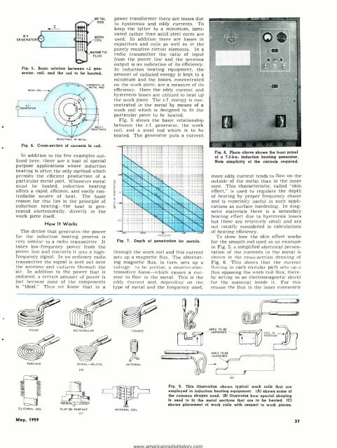
Fig. 7.<br />
Depth of penetration for metals.<br />
through the work coil and this current<br />
sets up a magnetic flux. The alternating<br />
magnetic flux, in turn, sets up a<br />
voltage to be precise, a counter -electromotive<br />
force -which causes a current<br />
to flow in the metal. This is the<br />
eddy current and, depending on the<br />
type of metal and the frequency used,<br />
Fig. 8. Photo above shows the front panel<br />
of a 7.5-kw. induction heating generator.<br />
Note simplicity of the controls required.<br />
more eddy current tends to flow on the<br />
outside of the metal than in the inner<br />
core. This characteristic. called "skin<br />
effect." is used to regulate the depth<br />
of heating by proper frequency choice<br />
and is especially useful in such applications<br />
as surface hardening. In magnetic<br />
materials there is a secondary<br />
heating effect due to hysteresis losses<br />
but these are relatively small and are<br />
not usually considered in calculations<br />
of heating efficiency.<br />
To show how the skin effect works<br />
for the smooth rod used as an example<br />
in Fig. 5, a simplified electrical presentation<br />
of the currents in the metal is<br />
shown in the cross -section drawing of<br />
Fig. 6. This shows that the current<br />
flowing in each circular path sets up a<br />
flux opposing the work coil flux, thereby<br />
acting as an electromagnetic shield<br />
for the material inside it. For this<br />
reason the flux in the inner concentric<br />
ROUND<br />
RECTANGULAR<br />
FORMED<br />
AREA TO BE<br />
- HARDENED'<br />
AREA TO BE<br />
HARDENED<br />
PANCAKE<br />
SPIRAL -HELICAL<br />
INTERNAL<br />
(A)<br />
(B)<br />
;D<br />
`fID<br />
EXTERNAL COIL<br />
FLAT OR PANCAKE<br />
(C)<br />
INTERNAL COIL<br />
Fig. 9. This illustration shows typical work coils that are<br />
employed in induction heating equipment. (A) shows some of<br />
the common shapes used. (B) illustrates how special shaping<br />
is used to fit the metal sections that are to be heated. (C)<br />
shows placement of work coils with respect to work pieces.<br />
May. <strong>1959</strong><br />
37