Rio Descoberto Dam - International Congress of Large Dams-Montreál
RIO DESCOBERTO DAM: WATER SUPLLY SYSTEM FOR BRASÍLIA CITY- BRAZILREHABILITATION AND PERFORMANCE - Soares A., Viana M., Corrêa, Nelson LA, Corrêa Mariane, Sabino Freitas Correa, Francisco Andriolo Ito
RIO DESCOBERTO DAM:
WATER SUPLLY SYSTEM FOR BRASÍLIA CITY- BRAZILREHABILITATION
AND PERFORMANCE - Soares A., Viana M., Corrêa, Nelson LA, Corrêa Mariane, Sabino Freitas Correa, Francisco Andriolo Ito

You also want an ePaper? Increase the reach of your titles
YUMPU automatically turns print PDFs into web optimized ePapers that Google loves.
RIO DESCOBERTO DAM:<br />
WATER SUPLLY SYSTEM FOR BRASÍLIA CITY-<br />
BRAZILREHABILITATION AND PERFORMANCE
1<br />
COMMISSION INTERNATIONALE<br />
DES GRANDS BARRAGES<br />
------<br />
CONGRESS DES<br />
GRANDS BARRAGES<br />
MONTREAL, 2003<br />
------<br />
RIO DESCOBERTO DAM:<br />
WATER SUPLLY SYSTEM FOR BRASÍLIA CITY- BRAZIL-<br />
REHABILITATION AND PERFORMANCE ( R )<br />
Antônio Manoel SOARES Mércio VIANA<br />
Civil Engineers, CAESB- Cia. de Saneamento do Distrito Federal S/A<br />
Nelson L. A. CORRÊA Sabino Freitas CORRÊA Marianne Freitas CORRÊA<br />
Civil Engineers, ECL Engenharia e Construções Ltda. – SBS Quadra 02, Bloco “A", Sala 401, Brasília;<br />
Francisco Rodrigues ANDRIOLO<br />
Andriolo Ito Engenharia SC Ltda- Rua Cristalândia 181- Alto de Pinheiros- 05465-000- São Paulo- SP<br />
Tel: 5511 3022 5613; Fax: 5511 3022 7069- site: www.andriolo.com.br ; e-mail: fandrio@attglobal.net<br />
BRAZIL<br />
1.1- GENERAL DAM CONSTRUCTION DATA<br />
1- INTRODUCTION<br />
The <strong>Rio</strong> <strong>Descoberto</strong> <strong>Dam</strong> is located at 15 0 14’ south latitude and 48 0 16’<br />
west longitude, geographic coordinates, and can be accessed by the BR-070<br />
state paved road. The <strong>Dam</strong> is used as a reservoir for the Brazil’s Capital (Brasília<br />
City) water supply. At the spillway level the reservoir capacity is 1,000,000 m 3<br />
and approximately 60% <strong>of</strong> the local population water consumption is supplied by<br />
the <strong>Descoberto</strong> reservoir, serving up to 1,200,000 people. The dam is concrete<br />
gravity mass type with 54,500m 3 total concrete volume. The typical section is<br />
trapezoidal with a top elongation, 3 m crest wide, 33 m maximum height and 265<br />
m crest length.<br />
( R )-“Barrage du <strong>Rio</strong> <strong>Descoberto</strong>: Approvisionnement d’Eau pour la Ville de<br />
Brasilia-Brésil- Réhabilitation et Fonctionnement”
2<br />
<strong>Rio</strong> <strong>Descoberto</strong><br />
<strong>Dam</strong><br />
Brazil/ Bresil<br />
Barrage <strong>Rio</strong><br />
<strong>Descoberto</strong><br />
Brazília City<br />
Brazília Cité<br />
Figure 01- <strong>Rio</strong> <strong>Descoberto</strong> <strong>Dam</strong> localization<br />
Image 01- Barrage du <strong>Rio</strong> <strong>Descoberto</strong> – Localisation<br />
The <strong>Rio</strong> <strong>Descoberto</strong> <strong>Dam</strong> body can be divided in three main parts, the 125<br />
m length left abutment, 85 m length right abutment and the 55 m length central<br />
spillway (see Figure 02). The spillway is “Creager” type with a type II USBR<br />
dissipation basin.<br />
The dam construction was performed by blocks, separated by contraction<br />
joints, during the years 1971 and 1974. The concrete blocks placement sequence<br />
was intercalated. In each vertical contraction joint, between the concrete blocks,<br />
a water-stop “O” type (300*10mm) was used.<br />
The dam is composed <strong>of</strong> 18 blocks, named “A” to “R”. All the blocks are 15<br />
m wide, with the exception <strong>of</strong> “A” (10 m wide). The crest level is at El. 1,034m<br />
and the spillway level is at El. 1,030m.<br />
1.2- OPENING REMARKS<br />
The dam, mass concrete gravity type, was finished in 1974. Some leaching<br />
water started to be observed at the downstream face few years after the end <strong>of</strong><br />
the construction, and filling the reservoir.<br />
Some remedial works were adopted in different periods, as grouting and<br />
drainage systems, with no remarkable success. After these remedial works<br />
CAESB have adopted a new approach looking for the origin <strong>of</strong> the problems, to<br />
adopt a definitive solution. After several analyses, the problem origin diagnosis<br />
was the presence <strong>of</strong> pyrite in the concrete aggregate combined with the acidic<br />
water action.
3<br />
Figure 02- <strong>Dam</strong> plant, upstream view and sections<br />
Image 02- Plan du barrage, vue de l’amont et sections<br />
The consequences <strong>of</strong> pyrite composed concrete aggregate was known by<br />
the <strong>Descoberto</strong> <strong>Dam</strong> designers by the time <strong>of</strong> construction [01] , but the pale local<br />
experience with that kind <strong>of</strong> problems allowed the use <strong>of</strong> a low level pyrite<br />
concrete aggregate in this construction work. Posterior happenings including the<br />
pathologies observed at this dam, and the Fonsagrada <strong>Dam</strong> [02] collapse report<br />
from Spain, demonstrated however, that even very low pyrite levels on hydraulic<br />
structures concrete aggregate might cause serious problems.<br />
Few years after filling the reservoir, leakages started to be observed at the<br />
downstream block “I” face. At the end <strong>of</strong> the 70´s decade some wide fissures<br />
started to be observed too. From that time, until the performance <strong>of</strong> this project in<br />
2000, the water leakage increased strongly, becoming into long horizontal<br />
leaching planes across the dam section.<br />
1.3- CHRONOLOGY<br />
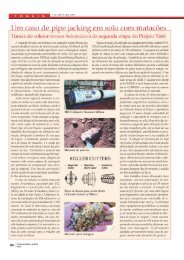
From the first problems appearing until the full rehabilitation diaphragm works,<br />
started in 2000, three remedial interventions were performed, without remarkable<br />
success. Those interventions were based in epoxy and grout injections. The<br />
summary <strong>of</strong> this chronology is displayed in the Figure 03, below.<br />
1.3.1- First Intervention<br />
Since the mid 70´s decade leakages were observed at the “I” block’s<br />
downstream face. In 1981, as usual in leakage dam treatment method, the first
4<br />
intervention was performed. The solution was based in epoxy injections applied<br />
from the downstream face<br />
Period 1970 1980 1990 2000<br />
Activity<br />
<strong>Dam</strong> Construction<br />
Initial Seepage<br />
Remarks<br />
First<br />
Interventions Second<br />
Third<br />
Diaphragm<br />
Wall<br />
Figure 03- Chronology <strong>of</strong> the interventions<br />
Image 03- Chronologie des actions<br />
1.3.2- Second Intervention<br />
Between 1989 October and 1990 July, the second intervention was<br />
performed. The works were guided by a preliminary diagnosis report made in<br />
1988. This report indicated concreting joints failures as the origin <strong>of</strong> the problem.<br />
These works consisted in the combination <strong>of</strong> grout injection filling at the upstream<br />
face with internal drainage holes near the downstream face.<br />
Right after the completion <strong>of</strong> these works dam appearance was satisfactory,<br />
without leakages at the downstream face and only some weak moisture spots<br />
could be observed at the upstream inspection gallery’s walls. The inspection<br />
gallery was satisfactory and the foundation drains <strong>of</strong> the dam were operating<br />
well.<br />
Unfortunately, just three years after the completion <strong>of</strong> these works, the dam<br />
structure was worse than it was before.<br />
1.3.3- Third Intervention<br />
In 1993 the <strong>Descoberto</strong> <strong>Dam</strong> was presenting serious problems. Moreover<br />
than the leaching horizontal planes at the downstream “E”, “I”, “G” and “O”<br />
block’s face with significant flow, the fissure problem had also increased. At the<br />
leaching blocks, new percolating horizontal planes raised. The inspection tunnel<br />
was flooded and full <strong>of</strong> carted material from the rock bottom drains.<br />
During the course <strong>of</strong> this intervention the Owner <strong>of</strong> the <strong>Dam</strong>, CAESB,<br />
decided to adopt a new approach in order to reach the cause <strong>of</strong> those chronic<br />
problems. At this time a Consultant Committee was constituted, formed by the<br />
Pr<strong>of</strong>. Dr.Victor de Mello, Eng. Francisco Andriolo and Eng. Walton Pacelli de<br />
Andrade. The committee recommended [03] the collection <strong>of</strong> samples <strong>of</strong> inner<br />
inspection gallery drains sediment, dam’s concrete, reservoir and drain water<br />
analyses.
5<br />
[04, 05]<br />
the<br />
The analyses indicated presence <strong>of</strong> pyrite in the concrete<br />
aggregate and foundations. The combination <strong>of</strong> the presence <strong>of</strong> that mineral with<br />
the action <strong>of</strong> acidic (pure) water, was contributing to the degeneration <strong>of</strong> the<br />
concrete structure <strong>of</strong> the <strong>Descoberto</strong> <strong>Dam</strong>. The main pathologies observed were<br />
pyrite reactions [02, 04 to 10] .<br />
The best solution was to implant a waterpro<strong>of</strong> barrier, avoiding the contact<br />
between the reservoir water and the body <strong>of</strong> the dam.<br />
The injection works were suspended and a 4.2m long pilot drive <strong>of</strong> the<br />
diaphragm secant piles wall was built for testing and experience purposes.<br />
2.1- GENERAL<br />
2- OWNER CONDITIONS - SITUATION ANALYSIS<br />
After the three interventions with no successful results, now with a deeper<br />
research <strong>of</strong> the problem developed by the committee, CAESB decided to fully<br />
rehabilitate the <strong>Descoberto</strong> <strong>Dam</strong>. Starting from the conclusions <strong>of</strong> the committee,<br />
observing the increase <strong>of</strong> the structural problems, CAESB started to search<br />
alternatives for the dam rehabilitation in order to bid the best options.<br />
Figure 04- Downstream face <strong>of</strong> “O”<br />
concrete block showing a great<br />
leakage<br />
Image 04- Parement aval, face du<br />
bloc en béton “0” montrant une<br />
grande fuite<br />
Figure 05- Internal part <strong>of</strong> the gallery<br />
showing the water flow<br />
Image 05- Côté interne de la gaIerie<br />
montrant le débit d’eau<br />
2.2- BASIC REQUIREMENTS<br />
Five basic requests were imposed by the owner for the rehabilitation<br />
techniques:<br />
I. The rehabilitation method must prevent the water access to the dam<br />
concrete body and foundations;<br />
II. The water supply must be fully maintained during the rehabilitation works;<br />
III. The water quality must be fully maintained during the rehabilitation works;
6<br />
IV. The method efficiency must be possible <strong>of</strong> being tested by sections during<br />
the performance <strong>of</strong> the rehabilitation works;<br />
V. Grouting based impermeabilization solutions wouldn’t be accepted.<br />
Figure 06- Brown material in the<br />
gallery floor<br />
Image 06- Matériel marron par terre<br />
dans la galerie<br />
Figure 07- Internal crack in the<br />
downstream zone <strong>of</strong> the galleryflow<br />
Image 07- Fissure interne sur le<br />
parement aval du débit de la galerie<br />
Figure 08- Downstream face <strong>of</strong> “O”<br />
concrete block_damaged by<br />
aggregate reaction<br />
Image 08- Parement aval, face du<br />
bloc en béton “0” endommagé par<br />
réaction du granulat<br />
Figure 09- Aggregate reaction at the<br />
upstream _face <strong>of</strong> the gallery<br />
Image 09- Réaction du granulat sur<br />
le parement amont de la galerie<br />
3- AVAILABLE METHODS<br />
After the definition <strong>of</strong> the owner conditions, four main rehabilitation methods<br />
were initially selected. One <strong>of</strong> these methods was based on the secant pile<br />
diaphragm wall experience from 1993 and the three remaining were solutions<br />
based in geocomposites barriers application, with some variations, as illustrated<br />
below.
7<br />
A – Alternative 1:<br />
Diaphragm wall across the<br />
body and concrete and<br />
foundations contact<br />
B - Alternative 2:<br />
Geocomposites applied<br />
by caisson<br />
C - Alternative 3:<br />
Geocomposites applied<br />
with an upper c<strong>of</strong>ferdam<br />
D - Alternative 4:<br />
Geocomposites applied<br />
combined with an<br />
underwater concrete mat<br />
A-Secant pile diaphragm wall,<br />
performed from the crest, drilling<br />
sequences near the upstream face<br />
reaching until 5m into the rock<br />
foundations<br />
C-Geocomposite barrier applied at<br />
the dry upstream <strong>of</strong> the dam after the<br />
construction <strong>of</strong> a c<strong>of</strong>ferdam<br />
B-Geocomposite barrier applied at the<br />
upstream face <strong>of</strong> the dam dried by<br />
caissons; the barrier would be applied<br />
from the maximum water level down to the<br />
reservoir bottom<br />
D-Geocomposite barrier underwater<br />
applied from the maximum water level<br />
down to the reservoir bottom, combined<br />
with inferior face and foundation<br />
protection by waterpro<strong>of</strong> concrete mat.<br />
Figure 10- Illustration <strong>of</strong> rehabilitation methods previous choice<br />
alternatives<br />
A- Mur diaphragme aux pieux<br />
sécants, performé à partir de la<br />
crête; séquences de perforation,<br />
près du parement amont, en<br />
atteignant jusqu’à 5m dans les<br />
rochers de fondations.<br />
C- Barrière géocomposite<br />
appliquée au parement amont<br />
du barrage après la<br />
construction d’un batardeau.<br />
B- Barrière géocomposite appliquée au<br />
parement amont du barrage, sechée par<br />
caissons; la barrière serait appliquée à<br />
partir du niveau maximum d’eau<br />
jusqu’au fond du réservoir.<br />
D- Barrière géocomposite sousmarine<br />
appliquée à partir du niveau maximum<br />
d’eau jusqu’au fond du réservoir,<br />
combinée avec le parement inférieur, et<br />
protection de fondation par une natte<br />
de béton sousmarin.<br />
Image 10- Illustration d’alternatives des choix préalables des méthodes de
8<br />
rehabilitation<br />
4- ADOPTED METHOD<br />
4.1- GENERAL<br />
The alternatives <strong>of</strong> application by caissons (B) and with the c<strong>of</strong>ferdam (C)<br />
were excluded, due to the fact that with these two alternatives was impossible to<br />
guarantee that the water supply and quality would be fully preserved during the<br />
works and these alternatives didn’t contemplate the foundation treatment and<br />
protection.<br />
After this selection CAESB bid the diaphragm wall and the underwater<br />
application geocomposite barrier alternatives. The ECL Engineering Ltd.<br />
Contractor won the bid <strong>of</strong>fering the method described by this paper. The cost <strong>of</strong><br />
that option was much lower than the underwater application geocomposite barrier<br />
option.<br />
4.2- CONCEPT<br />
The process concept is based on the construction <strong>of</strong> a waterpro<strong>of</strong> secant<br />
pile diaphragm wall inside the body <strong>of</strong> the dam, 70cm far from the upstream face.<br />
The diaphragm was performed from the dam crest without any interference with<br />
the reservoir water, need <strong>of</strong> water level drop or intake obstruction. The secant<br />
bores were performed in sequence by drilling equipment with the use <strong>of</strong> a special<br />
guiding template. A drilling sequence composes an up to 2.60m long panel. The<br />
minimum acceptable thickness <strong>of</strong> the diaphragm panels was 2”.<br />
The minimum thickness was mechanically tested and recorded by a VHS<br />
underwater system. After the completion <strong>of</strong> a drilled panel, it was filled by mortar<br />
using “tremie” system. After the mortar filling <strong>of</strong> a panel, the last bore <strong>of</strong> the filled<br />
panel is drilled again and this bore starts the next sequence (see Figure 11).<br />
During the drilling process the panels are always filled with water in order to<br />
provide equal pressures between the panel and the reservoir.<br />
Figure 11- Drilling sequence<br />
Image 11- Séquence de perforation<br />
Diaphragm drilling direction<br />
Diaphragm drilling sequence
9<br />
Figure 12- Transversal section with diaphragm insertion<br />
Image 12- Section transversale avec insertion de mur diaphragme<br />
4.3- FIRST EVALUATION<br />
Before the beginning <strong>of</strong> the diaphragm wall rehabilitation works, several<br />
additional tests, analyses, and stability calculations were performed. The scope<br />
included permeability, capillarity, compression and shearing tests at samples <strong>of</strong><br />
the pilot drive <strong>of</strong> the diaphragm drive built in 1993, collected with rotary drilling<br />
probe extractors. Shearing tests at samples extracted from the contact between<br />
the diaphragm mortar and the concrete <strong>of</strong> the dam were also performed, in order<br />
to check the adherence between these different materials.<br />
Additional stability analysis were made considering the extreme hypothesis<br />
<strong>of</strong> break <strong>of</strong> the small dam´s body part between the diaphragm and the upstream<br />
face. These calculations were made attending to a CAESB concern about the<br />
aggressive soluble effects <strong>of</strong> the s<strong>of</strong>t water <strong>of</strong> the reservoir, with very low solid<br />
suspensions, on the upper part <strong>of</strong> the dam that would be in contact with the<br />
water.<br />
That concern was also dissipated by the evidence that even being in<br />
contact with the water, that part has the reactive effects severely decreased after<br />
diaphragm insert as a consequence <strong>of</strong> the end <strong>of</strong> the reaction renovation and<br />
leaching. Laboratory tests have also been made with the mortar mixture indicated<br />
by the project designers and performance tests simulating the underwater mortar<br />
application conditions, in order to verify the possibility <strong>of</strong> segregation.<br />
5- PERFORMANCE AND LOGISTICS<br />
The works were performed by two main groups <strong>of</strong> activities, drilling teams<br />
and mortar underwater application team:
10<br />
5.1- DRILLING<br />
The drilling activities were performed with drilling equipments using DTH<br />
(down the hole) hammers, guided by a special alignment template developed for<br />
this project. The drilling machinery had to be adapted specifically for the project<br />
in order to have the drilling equipment tower aligned at the diaphragm axis.<br />
Figure 13- Drilling machine during<br />
operation<br />
Figure 14- Alignment template used<br />
for drilling control<br />
Image 13- Perforatrice en opération Image 14- Gabarit d’alignement<br />
utilisé pour contrôler la perforation<br />
Figure 15- Alternated drilling panels<br />
for the diaphragm<br />
Image 15- Panneaux alternés de<br />
perforation pour le diaphragme<br />
Figure 16- Inspecting the diaphragm<br />
panel with TV camera<br />
Image 16- Inspection du panneau du<br />
diaphragme avec une caméra de<br />
télévision
11<br />
Figure 17- Discharging the mortar<br />
from the truck mixer to the<br />
placement pump<br />
Image 17- Décharge du mortier de la<br />
bétonnière dans la pompe de<br />
placement<br />
Figure 18- Filling the drilled<br />
diaphragm panel with mortar by a<br />
“tremie” pipe<br />
Image 18- Remplissage du panneau<br />
perforé du diaphragme avec le<br />
mortier par un tuyau trémie<br />
The project included 70,000 meters <strong>of</strong> 6” and 6 ½” drilled bores in 18<br />
months <strong>of</strong> work in two shifts. Midsize drilling equipments were used in the project<br />
(with weight between 6 and 11ton). At the peak <strong>of</strong> production the job site had five<br />
drilling machines working at the same time, four at the dam crest and one at the<br />
spillway top. The deepest hole reached 38 m depth, at block “I”, and 22 meters<br />
was the average drilling depth <strong>of</strong> the project.<br />
Boring deviations caused by flexion were minimized by the use <strong>of</strong> 4” masts.<br />
Several types <strong>of</strong> bits were tested at this project, the concave and drop center<br />
types had to be remarked for their best performance and alignment. The guiding<br />
template was built machining heavy hot rolling steel pipe. The drilling sequence<br />
illustrated above at Figure 11 consists in drilling a panel first bore that works as a<br />
guide for the next using the template. Moreover than guidance, the template is<br />
necessary to avoid bores overlay.<br />
5.2- MORTAR PLACEMENT<br />
The mortar filling was made underwater with “tremie” type tube. The work<br />
was done from the dam crest. The “tremie” pipe was connected directly to the<br />
mortar pumping line. The mortar pumping was made from pumps positioned<br />
beside the drum mixer parking area at the abutments outside border. In<br />
occasions when the pumping distance was longer than 100 meters, two serial<br />
disposed pumps were used.<br />
Two operational problems had to be solved:<br />
• The total mortar volume applied at the project was not enough to assure<br />
the viability <strong>of</strong> the installation <strong>of</strong> a mixing plant at the job site;<br />
• The distance from the job site to the nearest local concrete mixing plant<br />
(approximately 60 Km) was too long, consuming more than 50% <strong>of</strong> the mortar<br />
lifetime in the journey.
12<br />
These problems were solved by the construction <strong>of</strong> a cement storage place<br />
and a dosage ramp. With these very simple devices, the dosage <strong>of</strong> cement and<br />
admixtures could be made at the job site into drum mixers loaded with the<br />
specified amount <strong>of</strong> sand and water. This procedure <strong>of</strong> dosage at the job site<br />
ended the mortar lifetime problems and enhanced the quality control.<br />
6.1- WATER QUALITY CONTROL<br />
6- QUALITY CONTROL<br />
The water supply for Brasília City, by the <strong>Rio</strong> <strong>Descoberto</strong> Reservoir system<br />
is made from an inlet at the “H” block upstream face. The water is pumped<br />
through a 48” welded steel sewer straight for a Water Treatment Plant<br />
approximately 5 Km farther. At the Water Treatment Plant inlet the turbidity,<br />
coloration and colliform rates at the water are continuously controlled. Those<br />
indexes were kept stable during the works. Samples <strong>of</strong> the reservoir water had<br />
also been collected during the project performance and analyzed, including the<br />
determination <strong>of</strong> solid particles in suspension rate. This rate was, in fact, very<br />
low, as it is normal in high altitudes. These analyses showed that the quality <strong>of</strong><br />
the water was not affected by the construction works.<br />
6.2- PROCESS CONTROL<br />
6.2.1- Water Losses Flow Control<br />
Since the beginning <strong>of</strong> the works, the downstream face and inspection<br />
gallery water loss flows were controlled. At the downstream face small wooden<br />
channels where installed, discharging in a collect point.<br />
Figure 19- Water seepage control during the remedial works<br />
Image 19- Contrôle de l’infiltration de l’eau pendant les travaux de<br />
réparation
13<br />
At the inspection tunnel the flow measurement was made straight into the<br />
upstream pressure relief drains. The measurement was made by graduated<br />
containers and chronometers. During the job, the flow was strongly decreased<br />
(99%).<br />
6.2.2- Diaphragm Continuity<br />
The continuity <strong>of</strong> the diaphragm panels was controlled by mechanical<br />
testing and underwater VHS video system. The mechanical test was made by<br />
letting down a steel plate with the minimum diaphragm thickness allowed (see<br />
Figure 14). This steel plate was suspended by two ropes, and this procedure was<br />
hand made in order to assure the necessary sensitivity. In case <strong>of</strong> any kind <strong>of</strong><br />
obstruction or discontinuity, the plate wouldn’t reach the bottom <strong>of</strong> the diaphragm<br />
panel. In case <strong>of</strong> persistence <strong>of</strong> doubt after the mechanical test, the VHS<br />
underwater camera was used to inspect the suspect drive (see Figure16). This<br />
video system was also used to check and register the contact between different<br />
drives.<br />
6.2.3- Mortar Control<br />
Besides the initial analyses made before starting the works, during the<br />
project all the mortar applied was controlled and tested. The controls were made<br />
by casting 10 cylindrical specimens at each truck mixer (6m3 capacity). From<br />
those ten specimens, four <strong>of</strong> them were experimented at compressive tests at 4-<br />
days age, four were tested at 28-days age and the two remaining were kept<br />
tagged with all the data concerning the mortar recorded. The average<br />
compressive strength was 27 MPa; 3-days, 7-days, 28-days and 63-days age<br />
testing series have also been made.<br />
Figures 20- Control <strong>of</strong> the mortar used<br />
Images 20- Contrôle du mortier utilisé
14<br />
6.2.4- Mortar Drilled Cores Tests<br />
Cores were drilled from the mortar placed in the diaphragm and tested. The<br />
following statistical data were obtained:<br />
Property<br />
Mortar<br />
(diaphragm)<br />
Interface<br />
Concrete<br />
(dam)-<br />
Mortar<br />
(diaphragm)<br />
Concrete<br />
(dam)<br />
Absorption (%) 1.22<br />
Specific Weight (t/m3) 1.97 – 2.08 2.52<br />
Permeability (m/s) 10 -11 – 10 -10<br />
Compressive Strength (MPa) 12.7 – 31.1 25.7<br />
Splitting Tensile Strength (MPa) 1.87 1.14 4.51<br />
Direct Tensile Strength (MPa) 1.07 – 1.80 2.32<br />
Shear Strength (MPa) under Normal<br />
Pressure: 2.0 MPa<br />
Shear Strength (MPa) under Normal<br />
Pressure: 4.0 MPa<br />
Shear Strength (MPa) under Normal<br />
Pressure: 6.0 MPa<br />
Figure 21- Statistical data from drilled cores<br />
Image 21- Données statistiques des noyaux perforés<br />
2.77 – 5.57 2.05 – 3.77 5.03 – 5.14<br />
3.92 – 6.63 3.10 – 3.66 6.43 – 6.76<br />
5.57 – 8.38 4.50 – 6.10 12.42<br />
Figure 21- Drilled cores from<br />
diaphragm mortar<br />
Image 21- Noyaux perforés du<br />
mortier du diaphragme<br />
Figure 22- Drilled cores from<br />
diaphragm mortar, interface, and<br />
from the old concrete from the dam<br />
Image 22- Noyaux perforés du<br />
mortier du diaphragme, contact<br />
entre couches et du vieux béton du<br />
barrage<br />
7- CONSTRUCTION CHRONOLOGY<br />
The drilling works started in September <strong>of</strong> 2000 at the block “Q”, this was<br />
the first block finished in January 2001. The average drilling rate was 5000 meter<br />
per month, and the peak drilling month rate was reached in June 2001 with 8000<br />
meters drilled in 30 days, working with five drilling equipments.
15<br />
Figure 23- Construction chronology<br />
Image 23- Chronologie de la construction<br />
Figure 24- <strong>Rio</strong> <strong>Descoberto</strong> <strong>Dam</strong> and Reservoir during the rehabilitation<br />
works<br />
Image 24- Barrage du <strong>Rio</strong> <strong>Descoberto</strong> et Réservoir pendant les travaux de<br />
réhabilitation<br />
8- COMMENTS AND CONCLUSIONS<br />
The methodology adopted for the <strong>Rio</strong> <strong>Descoberto</strong> concrete dam<br />
rehabilitation was successful to reach the following purposes:<br />
<br />
<br />
<br />
<br />
Less expensive <strong>of</strong>fer;<br />
Guarantee the water supply in terms <strong>of</strong> quantity (no interruption) and<br />
quality;<br />
Reduce the water leakage to a normal level;<br />
Rehabilitate the dam structural safety<br />
Since the <strong>Rio</strong> <strong>Descoberto</strong> <strong>Dam</strong> rehabilitation start-up, the water losses have<br />
been measured and at the blocks completed until January 2002 (all <strong>of</strong> them with<br />
exception <strong>of</strong> the “I” block), the loss flow has decreased from 34 l/s to 0,3 l/s. The<br />
last block under rehabilitation work in 2002 January, the “I” block, had the flow<br />
reduced from 15 l/s to 2,0 l/s with only 80% <strong>of</strong> this block diaphragm wall<br />
completed at that time. The first blocks completed in January and February
16<br />
2000, the “Q” and “C” blocks, had no maintenance since then and remained with<br />
the same initial efficiency.<br />
The method attended to all the technical requests presented by the Owner,<br />
CAESB, preserving the reservoir’s water quality and keeping the CAESB<br />
capability <strong>of</strong> water supply along the course <strong>of</strong> the works, without any kind <strong>of</strong><br />
problems or disturbance for the Brazil’s Capital inhabitants.<br />
ACKNOWLEDGEMENT<br />
The contributions and recommendations from Pr<strong>of</strong>. Dr. Victor F.B. de Mello<br />
are greatly acknowledged<br />
REFERENCES<br />
[01] – PETRUCCI, ELADIO ENG.;BASÍLIO, FRANCISCO ASSIS PROF.- “Estudo da<br />
influência da Pirita nos agregados calcareos para a Barragem do <strong>Rio</strong><br />
<strong>Descoberto</strong>”, Geotécnica , Brasília, 12/1972,CAESB.<br />
[02]- GUERREIRO, M., FERNANDEZ CUEVAS, R., GUERREIRO, MA.J., GOMEZ LAA, G.-<br />
“Causes <strong>of</strong> failure <strong>of</strong> the Fonsagrada <strong>Dam</strong>”- ICOLD- XVII <strong>Congress</strong> on <strong>Large</strong><br />
<strong>Dam</strong>s- Vienna (1991)- pp. 49- 63;<br />
[03]- MELLO, VICTOR F.B. PROF. DR. PHD., ANDRIOLO, FRANCISCO RODRIGUES<br />
ENG., PACELLI, WALTON ENG- “Visits and Technical Recommendations for<br />
the <strong>Rio</strong> <strong>Descoberto</strong> <strong>Dam</strong>”,-, Brasília, Brazil, April & June/1993,CAESB;<br />
[04]- SIGOLO, PROF. DR.; ASSUMÇÃO, J.C.B, GEOLOGIST - “Relatório referente a<br />
análise de sedimentos G (Galeria) e R (Reservatório) visando<br />
caracterização mineral”- São Paulo, 06/1993, CAESB;<br />
[05]- SIGOLO, PROF. DR.; ASSUMÇÃO, J.C.B, GEOLOGIST- “Análise de amostras<br />
da Barragem do <strong>Rio</strong> <strong>Descoberto</strong>”, São Paulo, 02/1995, CAESB<br />
[06]- LEA, FREDERICK, M.- “The Chemistry <strong>of</strong> Cement and Concrete”- 3 rd<br />
Edition- Edward Arnold Publishers Ltd- Great Britain- 1970, pp.568-569<br />
[07]- “Exposure <strong>of</strong> <strong>Dam</strong> Concrete to Special Aggressive Waters” – ICOLD<br />
Bulletin 71- 1989- pp 19- 33;<br />
[08]- “Durability <strong>of</strong> Concrete Construction”- American Concrete Institute- pp.<br />
81- 85;<br />
[09]- CÁNOVAS, MANUEL FERNÁNDEZ- “Patologia e Terapia do Concreto<br />
Armado”- Editora Pini- São Paulo- Brazil- 1988- pp.37- 245;<br />
[10]- NEVILLE, A. M.- “Properties <strong>of</strong> Concrete”- 2 nd Edition- Halsted Press- John<br />
Wiley & Sons Inc. New York- 1973. pp.- 134- 137;<br />
[11]- “Recuperação da Barragem do <strong>Rio</strong> <strong>Descoberto</strong>- Histórico Sucinto- No.<br />
2”- CAESB- 01/1999;
17<br />
[12]- MELLO, VICTOR F.B. PROF. DR. PHD., ANDRIOLO, FRANCISCO RODRIGUES<br />
ENG., PACELLI, WALTON ENG- “Visits and Technical Recommendations for<br />
the <strong>Rio</strong> <strong>Descoberto</strong> <strong>Dam</strong>”,-, Brasília, Brazil, December/1999,CAESB;<br />
[13]- PACELLI, WALTON , ENG.; BITTENCOURT, RUBENS M.,ENG., ALBUQUERQUEM<br />
ALBÉRIA CAVALCANTI, ENG. MSC- “Ensaios com Testemunhos de Argamassa<br />
e Concreto”, Laboratório de Furnas 06/2001, CAESB.<br />
SUMMARY<br />
The <strong>Rio</strong> <strong>Descoberto</strong> <strong>Dam</strong>, owned by CAESB - Companhia de Saneamento<br />
do Distrito Federal - Brazil, is used as a reservoir for water supply to Brasilia City<br />
- Capital <strong>of</strong> Brazil.<br />
The dam, mass concrete gravity type, was finished in 1974. Some leaching<br />
water started to be observed at the downstream face since few years after the<br />
end <strong>of</strong> the construction, and filling <strong>of</strong> the reservoir.<br />
Some remedial works were adopted in different periods, as grouting and<br />
drainage systems, with no remarkable success. After these remedial works,<br />
CAESB have adopted a new approach looking for the origin <strong>of</strong> the problems, to<br />
adopt a definitive solution. After several analyses, the problem origin diagnosis<br />
was the presence <strong>of</strong> pyrite in the concrete aggregate combined with the acidic<br />
water action.<br />
A diaphragm wall was adopted as the rehabilitation methodology. This “ In<br />
the wet” technique, permitted the water supply for Brasilia (1.2 million people) not<br />
to be interrupted or affected in the course <strong>of</strong> the rehabilitation works. The<br />
reservoir’s water quality was continuously controlled during the process, and kept<br />
at the same level. The adopted methodology is described in this paper.<br />
RÉSUMÉ<br />
Le Barrage du <strong>Rio</strong> <strong>Descoberto</strong>, propriété de CAESB - Companhia de<br />
Saneamento do Distrito Federal - Brésil, est utilisé comme un réservoir de<br />
approvisionnement d’eau pour la ville de Brasilia – Capitale du Brésil.<br />
Le barrage, type barrage-poids en béton de masse, a été terminé en 1974.<br />
De l’eau de lessivage a été observée sur le parement aval depuis quelques<br />
années après la fin de la construction et remplissage du réservoir.<br />
Quelques travaux de réparation ont été adoptés dans différentes périodes,<br />
comme injection et systèmes de drainage, sans un succès expressif. Après ces<br />
travaux de réparation, CAESB a adopté un nouveau approche en cherchant<br />
l’origine des problèmes, pour adopter une solution en définitive. Après plusieurs<br />
analyses, le diagnostic du problème était la présence de pyrite dans le granulat<br />
de béton combiné avec l’action acide de l’eau.<br />
Un mur diaphragme a été adopté comme la méthodologie de réhabilitation.<br />
Cette technique “à mouillé” a permis l’approvisionnement d’eau pour Brasilia (1.2<br />
millions de personnes) de ne pas être interrompu ou affecté au cours des travaux<br />
de réhabilitation. La qualité de l’eau du réservoir a été continuellement contrôlée
18<br />
durant le procès et a été maintenue au même niveau. La méthodologie adoptée<br />
est décrite dans ce travail.