
Create successful ePaper yourself
Turn your PDF publications into a flip-book with our unique Google optimized e-Paper software.
Fluorocarbon film liners are available as an additional corrosion barrier<br />
attached to the inlet side of the SKR-U Rupture Disk. FEP is the standard<br />
liner material. PFA and PTFE may be available upon special<br />
request. Teflon ® materials are typically used. Teflon ® is a DuPont trademark.<br />
Temperature<br />
The design temperature for the UR-2 Union <strong>Safety</strong> Head is 700 deg<br />
F/371 deg C. All of the standard holder and rupture disk materials are<br />
available up to this limit except for Titanium & Tantalum. Titanium is<br />
limited to 572 deg F/300 deg C, and Tantalum is limited to 500 deg<br />
F/260 deg C. The temperature limits for Fluorocarbon liners are shown<br />
in the table below.<br />
Fluorocarbon Liner (FEP) 400° F 204° C<br />
Fluorocarbon Liner (PFA) 400° F 204° C<br />
Fluorocarbon Liner (PTFE) 500° F 260° C<br />
Thread Connection Options<br />
While the standard thread connections are 1/2", 3/4" and 1" NPT<br />
female inlet & outlet, alternatives are available by special request that will<br />
fit within the same overall dimensions.<br />
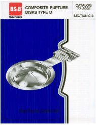
Rupture Disk Design<br />
The SKR-U Rupture Disk takes its design from the solid metal SKR <br />
reverse buckling disk that is used in flange type safety heads. The SKR-<br />
U Rupture Disk has a unique hinge and tag design that allows it to be<br />
used in the screw type UR-2 Union holder.<br />
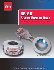
The SKR-U reverse buckling disk is designed with a circular score line<br />
located at the edge of the domed area, on the downstream side of the<br />
disk. At the burst pressure, the disk's dome reverses and opens by shearing<br />
around the circular score line. The use of SAF technology<br />
(Structural Apex Forming) enables accuracy of burst pressure to be<br />
maintained in a union type holder where other technology is highly<br />
torque sensitive.<br />
Pressure Tolerances<br />
BS&B applies both a burst tolerance and a manufacturing design range<br />
to the SKR-U Rupture Disk. Whether North American<br />
ASME, European or ISO standards are followed, the<br />
approach is the same.<br />
Burst tolerance is the +/- range of pressure over which a<br />
rupture disk can be expected to burst. Manufacturing<br />
Design Range is a range of pressure, always applied to the<br />
minus side of the user requested burst pressure for the<br />
SKr-U, that simplifies disk fabrication testing and provides<br />
economic benefit to the user where such an added tolerance<br />
can be accommodated by the application.<br />
Burst tolerance is either +/-5% of burst pressure or +/-<br />
2psi/+/-0.138 bar for disks rated below 40 psi/2.76 bar.<br />
Manufacturing Design Range (MDR) Choices Are Provided For<br />
SKr-U Rupture Disks<br />
MDR = 0 :where the user requires the tightest margin<br />
between normal service pressure and set pressure,<br />
a zero MDR disk shall be used.<br />
MDR = -5% :applied to the requested burst pressure,<br />
a -5% MDR allows an additional 5% tolerance<br />
applied on the minus side of the user requested<br />
burst pressure.<br />
MDR = -10% :applied to the requested burst pressure,<br />
a -10% MDR allows an additional 10% tolerance<br />
applied on the minus side of the user requested<br />
burst pressure.<br />
MDR and burst tolerance are additive. In the European & ISO<br />
cases, the burst tolerance and MDR are combined. In the ASME<br />
case, the 'marked burst pressure' must be a value within the agreed<br />
manufacturing design range and then the burst tolerance is applied.<br />
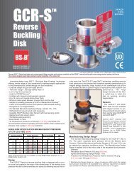
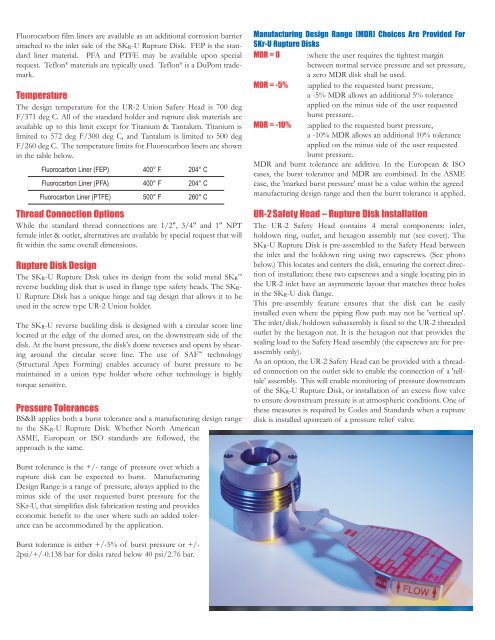
UR-2 <strong>Safety</strong> Head – Rupture Disk Installation<br />
The UR-2 <strong>Safety</strong> Head contains 4 metal components: inlet,<br />
holdown ring, outlet, and hexagon assembly nut (see cover). The<br />
SKR-U Rupture Disk is pre-assembled to the <strong>Safety</strong> Head between<br />
the inlet and the holdown ring using two capscrews. (See photo<br />
below.) This locates and centers the disk, ensuring the correct direction<br />
of installation: these two capscrews and a single locating pin in<br />
the UR-2 inlet have an asymmetric layout that matches three holes<br />
in the SKR-U disk flange.<br />
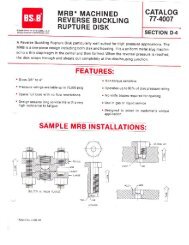
This pre-assembly feature ensures that the disk can be easily<br />
installed even where the piping flow path may not be 'vertical up'.<br />
The inlet/disk/holdown subassembly is fixed to the UR-2 threaded<br />
outlet by the hexagon nut. It is the hexagon nut that provides the<br />
sealing load to the <strong>Safety</strong> Head assembly (the capscrews are for preassembly<br />
only).<br />
As an option, the UR-2 <strong>Safety</strong> Head can be provided with a threaded<br />
connection on the outlet side to enable the connection of a 'telltale'<br />
assembly. This will enable monitoring of pressure downstream<br />
of the SKR-U Rupture Disk, or installation of an excess flow valve<br />
to ensure downstream pressure is at atmospheric conditions. One of<br />
these measures is required by Codes and Standards when a rupture<br />
disk is installed upstream of a pressure relief valve.