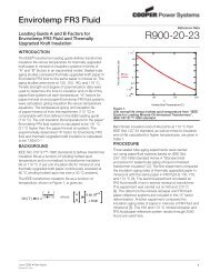
Envirotemp ® FR3 ® Fluid - Waukesha Electric
Envirotemp ® FR3 ® Fluid - Waukesha Electric
Envirotemp ® FR3 ® Fluid - Waukesha Electric

You also want an ePaper? Increase the reach of your titles
YUMPU automatically turns print PDFs into web optimized ePapers that Google loves.
<strong>Envirotemp</strong> <strong>®</strong> <strong>FR3</strong> <strong>®</strong> <strong>Fluid</strong><br />
6 June 2007<br />
Cooper Power Systems Cooper Power Systems<br />
McGraw-Edison Development Corporation 1900 East North Street<br />
19, Mykinon Street <strong>Waukesha</strong>, Wisconsin 53188-3899<br />
GR-166 74 Glyfada, Athens USA<br />
GREECE<br />
telephone: +30 210 964 6332 telephone: +01 262 524 3300<br />
email: cps-athens@cooperpower.com<br />
<strong>®</strong>
Contents<br />
1. Dielectric properties<br />
1.1. Partial discharge behavior .................................................................................................... 4<br />
1.2. Withstand capability curves .................................................................................................. 5<br />
1.3. Effect of dissolved water and temperature on dielectric strength ......................................... 7<br />
1.4. Effect of voltage distribution in insulation structure ............................................................... 8<br />
1.5. Effect of temperature on power factor and dielectric constant ............................................. 8<br />
1.6. Creep withstand .................................................................................................................. 10<br />
2. Thermal properties<br />
2.1. Viscosity at low temperatures ............................................................................................. 11<br />
3. Ageing<br />
3.1. Oxidation inhibitors .............................................................................................................. 11<br />
3.2. Transport atmosphere ......................................................................................................... 11<br />
3.3. Long term ageing fluid properties ....................................................................................... 12<br />
3.4. Impact of moisture and dissolved oxygen on ageing .......................................................... 15<br />
3.5. Dissolved oxygen ................................................................................................................ 15<br />
3.6. Causes of dissolved gas ..................................................................................................... 15<br />
3.7. Typical dissolved gas spectra ............................................................................................. 15<br />
3.8. Dissolved gas and ageing ................................................................................................... 16<br />
3.9. Sensitivity to oxygen of immersed material in air ................................................................ 17<br />
3.10. Normal gassing ................................................................................................................... 18<br />
3.11. Effectiveness of gas extraction ........................................................................................... 19<br />
3.12. Interpretation of dissolved gas data .................................................................................... 19<br />
4. General properties<br />
4.1. <strong>Fluid</strong> preservation ................................................................................................................ 19<br />
4.2. Materials compatibility ......................................................................................................... 19<br />
4.3. Water absorption during maintenance and on-site drying .................................................. 20<br />
4.4. Measures to avoid polymerization ...................................................................................... 20<br />
4.5. Traces of other liquids ......................................................................................................... 20<br />
4.6. Aging rate of thermal upgraded paper ................................................................................ 21<br />
4.7. Electrostatic charging and streaming electrification ............................................................ 22<br />
5. Handling / oil processing<br />
2<br />
5.1. Processing rigs .................................................................................................................... 22<br />
5.2. Impregnating solid insulation .............................................................................................. 22<br />
5.3. Influence of other oils and synthetic liquids during degassing ............................................ 22<br />
5.4. Disposal methods ................................................................................................................ 22<br />
5.5. Hydrolytic stability ............................................................................................................... 22
5.6. Processing for water content .............................................................................................. 22<br />
5.7. Vapor phase processing ..................................................................................................... 22<br />
References .......................................................................................................................................... 22<br />
3
1. Dielectric properties<br />
Partial Discharge Inception (kV)<br />
4<br />
1.1 Partial discharge behavior<br />
<strong>Envirotemp</strong> <strong>FR3</strong> fluid appears to have a higher partial discharge inception voltage compared to<br />
mineral oil.<br />
40<br />
30<br />
20<br />
10<br />
Figure 1 shows results obtained by the<br />
University of New South Wales using<br />
needle to spherical section geometry [1].<br />
Water was added to the fluids for the 4<br />
mm gap tests, resulting in a much smaller<br />
inception voltage for both fluids.<br />
The breakdown voltages of the two fluids<br />
are quite different, however. <strong>Envirotemp</strong><br />
<strong>FR3</strong> fluid has a much higher breakdown<br />
voltage compared to mineral oil. This may<br />
be attributed to its higher tolerance of<br />
water.<br />
Figures 2-4 show results from the<br />
University of Hannover [2] using the<br />
IEC 61294 method and a 50mm gap.<br />
The variations of partial discharge<br />
inception with regard to temperature<br />
and relative water content were<br />
explored. At low relative saturations,<br />
mineral oil and <strong>Envirotemp</strong> <strong>FR3</strong> fluid<br />
have similar inception voltages. As the<br />
relative water contents increase,<br />
<strong>Envirotemp</strong> <strong>FR3</strong> fluid appears to have<br />
higher inception voltages compared to<br />
mineral oil.<br />
IEC 61294, needle-plane, 50mm gap, University of Hanover<br />
<strong>Envirotemp</strong> <strong>FR3</strong> fluid (50 o C)<br />
mineral oil (60 o C)<br />
0<br />
0 5 10 15 20 25 30 35<br />
Water Content as Relative Saturation (%)<br />
Figure 3. Partial discharge inception voltage versus<br />
water content of mineral oil at 60°C and <strong>Envirotemp</strong><br />
<strong>FR3</strong> fluid at 50°C. [2]<br />
Voltage (kV)<br />
20<br />
15<br />
10<br />
5<br />
0<br />
transformer oil <strong>Envirotemp</strong> <strong>FR3</strong> fluid<br />
inception breakdown inception breakdown inception breakdown<br />
2 mm gap 3 mm gap 4 mm gap + H2O<br />
Partial Discharge (point - semisphere)<br />
Figure 1. Partial discharge inception voltage for<br />
mineral oil and <strong>Envirotemp</strong> <strong>FR3</strong> fluid. [1]<br />
Partial Discharge Inception (kV)<br />
Partial Discharge Inception (kV)<br />
40<br />
30<br />
20<br />
10<br />
<strong>Envirotemp</strong> <strong>FR3</strong> fluid: needle-plane<br />
<strong>Envirotemp</strong> <strong>FR3</strong> fluid: needle-sphere<br />
IEC 61294, 50mm gap, University of Hanover<br />
mineral oil: needle-plane<br />
mineral oil: needle-sphere<br />
0<br />
0 20 40 60 80<br />
Water Content as Relative Saturation at 20 o C (%)<br />
Figure 2. Partial discharge inception voltage versus<br />
water content of mineral oil and <strong>Envirotemp</strong> <strong>FR3</strong><br />
fluid at 20°C. [2]<br />
40<br />
30<br />
20<br />
10<br />
IEC 61294, needle-plane, 50mm gap, University of Hanover<br />
<strong>Envirotemp</strong> <strong>FR3</strong> fluid<br />
mineral oil<br />
0<br />
0 2 4 6 8 10 12 14 16 18 20<br />
Water Content as Relative Saturation at 90 o C (%)<br />
Figure 4. Partial discharge inception voltage versus<br />
water content of mineral oil and <strong>Envirotemp</strong> <strong>FR3</strong> fluid<br />
at 90°C. [2]
1.2 Withstand capability curves<br />
Oil gap withstand tests were conducted at three laboratories according to their voltage<br />
capabilities: Cooper Power Systems, Doble Engineering, and <strong>Waukesha</strong> <strong>Electric</strong> Systems. Figure<br />
5 shows the electrode configurations. Withstand capabilities for 60 Hz (Figure 6), full wave<br />
negative and positive impulse (Figure 7), chopped wave negative and positive impulse (Figure 8),<br />
and switching surge negative and positive impulse (Figure 9) are shown.<br />
Sphere-to-sphere full wave negative impulse withstand is shown in Figure 10. The University of<br />
Manchester used the ASTM D3300 test method with a 12.7mm gap.<br />
All of the results demonstrate that the oil gap withstand capabilities of mineral oil and <strong>Envirotemp</strong><br />
<strong>FR3</strong> fluid are, for all practical purposes, equivalent.<br />
(a) (b) (c)<br />
Figure 5. Electrode configurations for oil gap tests performed at the Thomas A. Edison Technical Center (a), Doble<br />
Engineering (b), and <strong>Waukesha</strong> <strong>Electric</strong> Systems (c).<br />
60 Hz Breakdown (kV/mm)<br />
100<br />
10<br />
Doble<br />
Engineering<br />
<strong>Waukesha</strong><br />
<strong>Electric</strong> Systems<br />
Thomas A. Edison<br />
Technical Center<br />
mineral oil<br />
<strong>Envirotemp</strong> <strong>FR3</strong> fluid<br />
mineral oil<br />
<strong>Envirotemp</strong> <strong>FR3</strong> fluid<br />
mineral oil<br />
<strong>Envirotemp</strong> <strong>FR3</strong> fluid<br />
1<br />
1 10 100<br />
Oil Gap (mm)<br />
Figure 6. AC withstand for mineral oil and <strong>Envirotemp</strong><br />
<strong>FR3</strong> fluid.<br />
Full Wave Negative Impulse (kV/mm)<br />
Full Wave Positive Impulse (kV/mm)<br />
100<br />
10<br />
Doble<br />
Engineering<br />
<strong>Waukesha</strong><br />
<strong>Electric</strong> Systems<br />
Thomas A. Edison<br />
Technical Center<br />
mineral oil<br />
<strong>Envirotemp</strong> <strong>FR3</strong> fluid<br />
mineral oil<br />
<strong>Envirotemp</strong> <strong>FR3</strong> fluid<br />
mineral oil<br />
<strong>Envirotemp</strong> <strong>FR3</strong> fluid<br />
1<br />
1 10 100<br />
100<br />
10<br />
Doble<br />
Engineering<br />
<strong>Waukesha</strong><br />
<strong>Electric</strong> Systems<br />
Thomas A. Edison<br />
Technical Center<br />
Oil Gap (mm)<br />
(a)<br />
mineral oil<br />
<strong>Envirotemp</strong> <strong>FR3</strong> fluid<br />
mineral oil<br />
<strong>Envirotemp</strong> <strong>FR3</strong> fluid<br />
mineral oil<br />
<strong>Envirotemp</strong> <strong>FR3</strong> fluid<br />
1<br />
1 10 100<br />
Oil Gap (mm)<br />
Figure 7. Negative (a) and positive (b) full wave<br />
impulse withstand for mineral oil and <strong>Envirotemp</strong> <strong>FR3</strong><br />
fluid.<br />
(b)<br />
5
Chopped Wave Negative Impulse (kV/mm)<br />
Chopped Wave Positive Impulse (kV/mm)<br />
100<br />
10<br />
Doble<br />
Engineering<br />
Thomas A. Edison<br />
Technical Center<br />
mineral oil<br />
<strong>Envirotemp</strong> <strong>FR3</strong> fluid<br />
mineral oil<br />
<strong>Envirotemp</strong> <strong>FR3</strong> fluid<br />
1<br />
1 10 100<br />
Oil Gap (mm)<br />
Figure 8. Chopped wave negative (a) and positive (b)<br />
impulse withstand for mineral oil and <strong>Envirotemp</strong> <strong>FR3</strong><br />
fluid.<br />
Full Wave Negative Impulse (kV/mm)<br />
100<br />
20<br />
15<br />
10<br />
5<br />
0<br />
10<br />
Doble<br />
Engineering<br />
Thomas A. Edison<br />
Technical Center<br />
(a)<br />
mineral oil<br />
<strong>Envirotemp</strong> <strong>FR3</strong> fluid<br />
mineral oil<br />
<strong>Envirotemp</strong> <strong>FR3</strong> fluid<br />
1<br />
1 10 100<br />
Oil Gap (mm)<br />
(b)<br />
ASTM D3300, sphere-sphere, 12.7mm gap, University of Manchester<br />
Absolute Water Content (mg/kg)<br />
mineral oil<br />
<strong>Envirotemp</strong> <strong>FR3</strong> fluid<br />
0 100 200 300 400<br />
Switching Surge Negative Impulse (kV/mm)<br />
Switching Surge Positive Impulse (kV/mm)<br />
100<br />
10<br />
Doble<br />
Engineering<br />
<strong>Waukesha</strong><br />
<strong>Electric</strong> Systems<br />
Thomas A. Edison<br />
Technical Center<br />
mineral oil<br />
<strong>Envirotemp</strong> <strong>FR3</strong> fluid<br />
mineral oil<br />
<strong>Envirotemp</strong> <strong>FR3</strong> fluid<br />
mineral oil<br />
<strong>Envirotemp</strong> <strong>FR3</strong> fluid<br />
1<br />
1 10 100<br />
100<br />
10<br />
Doble<br />
Engineering<br />
<strong>Waukesha</strong><br />
<strong>Electric</strong> Systems<br />
Thomas A. Edison<br />
Technical Center<br />
Oil Gap (mm)<br />
(a)<br />
mineral oil<br />
<strong>Envirotemp</strong> <strong>FR3</strong> fluid<br />
mineral oil<br />
<strong>Envirotemp</strong> <strong>FR3</strong> fluid<br />
mineral oil<br />
<strong>Envirotemp</strong> <strong>FR3</strong> fluid<br />
1<br />
1 10 100<br />
Oil Gap (mm)<br />
(b)<br />
Figure 9. Switching surge negative (a) and positive (b)<br />
impulse withstand for mineral oil and <strong>Envirotemp</strong> <strong>FR3</strong><br />
fluid.<br />
0<br />
0 10 20 30 40<br />
Relative Water Content (% 20 o C saturation)<br />
(a) (b)<br />
Figure 10. Full wave negative impulse strength versus absolute water content (a) and relative water content (b) of<br />
mineral oil and <strong>Envirotemp</strong> <strong>FR3</strong> fluid. [2]<br />
6<br />
Full Wave Negative Impulse (kV/mm)<br />
20<br />
15<br />
10<br />
5<br />
ASTM D3300, sphere-sphere, 12.7mm gap, University of Manchester<br />
mineral oil<br />
<strong>Envirotemp</strong> <strong>FR3</strong> fluid
D1816 Dielectric Breakdown Strength (kV)<br />
D1816 Dielectric Breakdown Strength (kV)<br />
1.3 Effect of dissolved water and temperature on dielectric strength<br />
The dependence of dielectric breakdown strength on water content is shown in Figures 11-13.<br />
Variation of ASTM D1816 (VDE electrodes) dielectric breakdown strength in term of both absolute<br />
and relative water contents are shown for 2mm gap (Figure 11) and 1mm gap (Figure 12). The<br />
ASTM D877 (disk electrodes) dependence on absolute water content is shown in Figure 13.<br />
80<br />
70<br />
60<br />
50<br />
40<br />
30<br />
20<br />
10<br />
Dielectric breakdown strength variation with temperature is given in Figure 14.<br />
0<br />
0 100 200 300 400 500 600 700<br />
Water Content (mg/kg)<br />
(a)<br />
(b)<br />
<strong>Envirotemp</strong> <strong>FR3</strong> fluid<br />
mineral oil<br />
Figure 11. Dielectric breakdown strength versus water<br />
content for mineral oil and <strong>Envirotemp</strong> <strong>FR3</strong> fluid.<br />
D 877 Dielectric Breakdown (kV)<br />
80<br />
70<br />
60<br />
50<br />
40<br />
30<br />
20<br />
10<br />
0<br />
0 20 40 60 80 100 120 140 160 180 200<br />
80<br />
70<br />
60<br />
50<br />
40<br />
30<br />
20<br />
10<br />
Water Content (% of 20 o C saturation)<br />
Water Content (ppm)<br />
<strong>Envirotemp</strong> <strong>FR3</strong> fluid<br />
mineral oil<br />
<strong>Envirotemp</strong> <strong>FR3</strong> fluid<br />
<strong>FR3</strong> production history<br />
conventional transformer oil<br />
0<br />
0 100 200 300 400 500 600<br />
Figure 13. Dielectric breakdown strength versus water<br />
content for mineral oil and <strong>Envirotemp</strong> <strong>FR3</strong> fluid.<br />
Dielectric Breakdown Strength (kV)<br />
Dielectric Breakdown Strength (kV)<br />
50<br />
40<br />
30<br />
20<br />
10<br />
0<br />
50<br />
40<br />
30<br />
20<br />
10<br />
ASTM D1816, 1mm gap, University of Manchester<br />
0 100 200 300 400<br />
Absolute Water Content (mg/kg)<br />
mineral oil<br />
<strong>Envirotemp</strong> <strong>FR3</strong> fluid<br />
(a)<br />
(b)<br />
mineral oil<br />
<strong>Envirotemp</strong> <strong>FR3</strong> fluid<br />
ASTM D1816, 1mm gap, University of Manchester<br />
0<br />
0 10 20 30 40<br />
Relative Water Content (% 20 o C saturation)<br />
Figure 12. Dielectric breakdown strength versus water<br />
content for mineral oil and <strong>Envirotemp</strong> <strong>FR3</strong> fluid. [3]<br />
D1816 Dielectric Breakdown Strength (kV)<br />
100<br />
80<br />
60<br />
40<br />
20<br />
0<br />
-40 -20 0 20 40 60<br />
Temperature ( o C)<br />
mineral oil<br />
<strong>Envirotemp</strong> <strong>FR3</strong> fluid<br />
Figure 14. Dielectric breakdown strength versus<br />
temperature for mineral oil and <strong>Envirotemp</strong> <strong>FR3</strong> fluid.<br />
7
Relative Permittivity<br />
8<br />
1.4 Effect of voltage distribution in insulation structure<br />
“The dielectric strength of solid insulation (in this case Kraft insulation impregnated with dielectric<br />
fluid) is close to an order of magnitude higher than the fluid itself. Thus the weak material in the<br />
insulation structure is the fluid. By bringing the permittivity of the liquid and solid insulation closer<br />
together more of the dielectric stress will be distributed in the solid material. This will reduce the<br />
stress in the fluid, which typically sets the design clearance.” T. Prevost, presentation of [4]<br />
An example is given in Figure<br />
28.<br />
ε1=permittivity fluid<br />
mineral oil ≅ 2 <strong>FR3</strong> fluid ≅ 3<br />
ε2=permittivity solid insulation<br />
solid insulation ≅ 4<br />
Z=(d1/ε1) + (d2/ε2)<br />
Let d1 = d2 = 5mm<br />
E1= U/(ε1 * Z)<br />
E2= U/(ε2 * Z)<br />
U= Applied Voltage<br />
Let U = 100 kV<br />
E1= Stress fluid<br />
E2= Stress in solid insulation<br />
Mineral oil:<br />
E1= 13.33 kV/mm<br />
E2= 6.67 kV/mm<br />
<strong>Envirotemp</strong> <strong>FR3</strong> fluid:<br />
E1= 11.43 kV/mm<br />
E2= 8.57 kV/mm<br />
Figure 28. Dielectric breakdown strength versus temperature for mineral<br />
oil and <strong>Envirotemp</strong> <strong>FR3</strong> fluid. from T.A. Prevost presentation of [4]<br />
1.5 Effect of temperature on power factor and dielectric constant<br />
The dielectric constants of mineral oil and <strong>Envirotemp</strong> <strong>FR3</strong> fluid as a function of temperature are<br />
shown in Figure 14. The University of Hannover [2] values are the average dielectric constant for<br />
a range of water contents. The error bars represent the maximum and minimum dielectric<br />
constants. <strong>Envirotemp</strong> <strong>FR3</strong> fluid was tested at water contents of 30, 50, 200, and 500 mg/kg;<br />
mineral oil was tested at 11, 20, and 40 mg/kg. Figures 15-17 show the dielectric constants of<br />
impregnated solid insulation versus temperature.<br />
4.0<br />
3.5<br />
3.0<br />
2.5<br />
2.0<br />
1.5<br />
EHV Weidmann Thomas A. Edison Technical Center University of Hannover<br />
mineral oil mineral oil<br />
mineral oil<br />
<strong>FR3</strong> fluid <strong>FR3</strong> fluid<br />
-20 0 20 40 60 80 100 120<br />
Temperature ( o C)<br />
<strong>FR3</strong> fluid<br />
Figure 14. Relative permittivity versus temperature of<br />
mineral oil and <strong>Envirotemp</strong> <strong>FR3</strong> fluid.<br />
Diamond Pattern Paper<br />
Relative Permittivity<br />
5.5<br />
5.0<br />
4.5<br />
4.0<br />
3.5<br />
20 40 60 80 100 120<br />
Temperature ( o C)<br />
mineral oil<br />
<strong>Envirotemp</strong> <strong>FR3</strong> fluid<br />
Figure 15. Relative permittivity versus temperature of<br />
Kraft paper impregnated with mineral oil and<br />
<strong>Envirotemp</strong> <strong>FR3</strong> fluid.
Medium Density Pressboard<br />
Relative Permittivity<br />
Dielectric <strong>Fluid</strong><br />
Dissipation Factor (%)<br />
Medium Density Pressboard<br />
Dissipation Factor (%)<br />
5.5<br />
5.0<br />
4.5<br />
4.0<br />
mineral oil<br />
<strong>Envirotemp</strong> <strong>FR3</strong> fluid<br />
3.5<br />
20 40 60 80 100 120<br />
Temperature ( o C)<br />
Figure 16. Relative permittivity versus temperature of<br />
T-IV pressboard impregnated with mineral oil and<br />
<strong>Envirotemp</strong> <strong>FR3</strong> fluid.<br />
10<br />
1<br />
0.1<br />
0.01<br />
0.001<br />
High Density Pressboard<br />
Relative Permittivity<br />
5.5<br />
5.0<br />
4.5<br />
4.0<br />
3.5<br />
20 40 60 80 100 120<br />
Temperature ( o C)<br />
mineral oil<br />
<strong>Envirotemp</strong> <strong>FR3</strong> fluid<br />
Figure 17. Relative permittivity versus temperature of<br />
Hi-Val pressboard impregnated with mineral oil and<br />
<strong>Envirotemp</strong> <strong>FR3</strong> fluid.<br />
Dissipation factors of mineral oil and <strong>Envirotemp</strong> <strong>FR3</strong> fluid as a function of temperature are shown<br />
in Figure 18. Again, the University of Hannover [2] values are the average dielectric constant for a<br />
range of water contents, and the error bars represent the maximum and minimum values. Figures<br />
19-21 show the dissipation factors of impregnated solid insulation versus temperature.<br />
University of Hannover<br />
mineral oil<br />
<strong>FR3</strong> fluid<br />
EHV Weidmann<br />
mineral oil<br />
<strong>FR3</strong> fluid<br />
0 20 40 60 80 100 120<br />
Temperature ( o C)<br />
Thomas A. Edison Technical Center<br />
mineral oil<br />
<strong>FR3</strong> fluid<br />
Figure 18. Dissipation factor versus temperature of<br />
mineral oil and <strong>Envirotemp</strong> <strong>FR3</strong> fluid.<br />
10<br />
1<br />
0.1<br />
0.01<br />
Temperature ( o C)<br />
mineral oil<br />
<strong>Envirotemp</strong> <strong>FR3</strong> fluid<br />
0.001<br />
20 40 60 80 100 120<br />
Figure 20. Dissipation factor versus temperature of T-IV<br />
pressboard impregnated with mineral oil and<br />
<strong>Envirotemp</strong> <strong>FR3</strong> fluid.<br />
Diamond Pattern Paper<br />
Dissipation Factor (%)<br />
10<br />
1<br />
0.1<br />
0.01<br />
0.001<br />
20 40 60 80 100 120<br />
Temperature ( o C)<br />
mineral oil<br />
<strong>Envirotemp</strong> <strong>FR3</strong> fluid<br />
Figure 19. Dissipation factor versus temperature of<br />
Kraft paper impregnated with mineral oil and<br />
<strong>Envirotemp</strong> <strong>FR3</strong> fluid.<br />
High Density Pressboard<br />
Dissipation Factor (%)<br />
10<br />
1<br />
0.1<br />
0.01<br />
0.001<br />
20 40 60 80 100 120<br />
Temperature ( o C)<br />
mineral oil<br />
<strong>Envirotemp</strong> <strong>FR3</strong> fluid<br />
Figure 21. Dissipation factor versus temperature of<br />
Hi-Val pressboard impregnated with mineral oil and<br />
<strong>Envirotemp</strong> <strong>FR3</strong> fluid.<br />
9
60 Hz Creep Breakdown Stress (kV/mm)<br />
60 Hz Creep Breakdown Stress<br />
Weibull 1% Probability (kV/mm)<br />
10<br />
1.6 Creep Withstand Capabilities<br />
AC and impulse creep withstand tests were performed by EHV Weidmann [4]. Their electrode<br />
configuration is shown in Figure 27. The geometry gives a non-uniform field with the highest<br />
stress along the pressboard-fluid interface. The electrode and test specimen are designed to<br />
minimize the effect of oil wedges.<br />
100<br />
10<br />
(a) (b)<br />
Figure 27. EHV Weidmann creep electrode design (a) and photo of creep<br />
breakdown (b). [4]<br />
1<br />
1 10 100<br />
100<br />
10<br />
EHV Weidmann<br />
mineral oil<br />
<strong>Envirotemp</strong> <strong>FR3</strong> fluid<br />
EHV Weidmann<br />
<strong>Envirotemp</strong> <strong>FR3</strong> fluid<br />
mineral oil<br />
Creep Distance (mm)<br />
(a)<br />
Weidmann design curve<br />
1<br />
1 10 100<br />
Creep Distance (mm)<br />
(b)<br />
Figure 22. 60 Hz creep strength of mineral oil and<br />
<strong>Envirotemp</strong> <strong>FR3</strong> fluid: (a) shows test values and (b)<br />
shows the calculated Weibull 1% probability.<br />
Full Wave Negative Creep<br />
Breakdown Stress (kV/mm)<br />
Full Wave Negative Creep<br />
Weibull 1% Probability (kV/mm)<br />
100<br />
10<br />
EHV Weidmann<br />
mineral oil<br />
<strong>Envirotemp</strong> <strong>FR3</strong> fluid<br />
1<br />
1 10 100<br />
100<br />
10<br />
EHV Weidmann<br />
<strong>Envirotemp</strong> <strong>FR3</strong> fluid<br />
mineral oil<br />
Weidmann design curve<br />
Creep Distance (mm)<br />
(a)<br />
1<br />
1 10 100<br />
Creep Distance (mm)<br />
(b)<br />
Figure 23. Full wave negative creep strength of<br />
mineral oil and <strong>Envirotemp</strong> <strong>FR3</strong> fluid: (a) shows test<br />
values and (b) shows the calculated Weibull 1%<br />
probability.
Full Wave Positive Creep<br />
Breakdown Stress ( kV/mm)<br />
100<br />
10<br />
For AC creep withstand (Figure 22) and negative full wave impulse creep withstand (Figure 23),<br />
the Weibull 1% probability is calculated and compared to the published Weidmann creep curve.<br />
Figure 24 shows the results to date for positive full wave impulse creep withstand. Tests<br />
completed to date demonstrate that the creep strengths of mineral oil and <strong>Envirotemp</strong> <strong>FR3</strong> fluid<br />
are, for all practical purposes, equivalent.<br />
EHV Weidmann<br />
mineral oil<br />
<strong>Envirotemp</strong> <strong>FR3</strong> fluid<br />
1<br />
1 10 100<br />
Creep Distance (mm)<br />
Figure 24. Full wave positive impulse creep withstand<br />
of mineral oil and <strong>Envirotemp</strong> <strong>FR3</strong> fluid<br />
2. Thermal properties<br />
1000<br />
100<br />
10<br />
Kinematic Viscosity (cSt) 10000<br />
2<br />
<strong>Envirotemp</strong> <strong>FR3</strong> fluid<br />
7-day hold<br />
conventional transformer oil<br />
-20 0 20 40 60 80 100 120 140<br />
Temperature ( o C)<br />
Figure 25. Viscosity versus temperature for mineral oil<br />
and <strong>Envirotemp</strong> <strong>FR3</strong> fluid<br />
2.1 Viscosity at low temperatures<br />
Many variables affect the low temperature flow characteristics of <strong>Envirotemp</strong> <strong>FR3</strong> fluid. The low<br />
temperature viscosity depends not only on the temperature, but also time at temperature, the rate<br />
of cooling, and the fluid volume. Figure 25 shows the viscosity versus temperature curves for<br />
mineral oil and <strong>Envirotemp</strong> <strong>FR3</strong> fluid. Comparing the 7-day hold values to the standard viscosity<br />
shows the time at temperature effect.<br />
3. Ageing<br />
(Another Cooper Power Systems’ product, R-Temp fluid, has a pour point similar to that of<br />
<strong>Envirotemp</strong> <strong>FR3</strong> fluid, but its viscosity is considerably higher. R-Temp fluid had the same cold flow<br />
concerns, but has had no field issues in 30+ years of cold climate applications.)<br />
3.1 Oxidation inhibitors<br />
<strong>Envirotemp</strong> <strong>FR3</strong> fluid contains an additive package that includes a proprietary oxidation inhibitor<br />
at 0.4 wt%. The ASTM D4768 gas chromatography method for determining the inhibitor content in<br />
insulating liquids can be used to determine the inhibitor content in <strong>Envirotemp</strong> <strong>FR3</strong> fluid.<br />
3.2 Transport atmosphere<br />
Tests using transformer power factor<br />
models are currently underway to evaluate<br />
the effects of dry air transport of<br />
transformers using <strong>Envirotemp</strong> <strong>FR3</strong> fluid.<br />
The pressboard models, impregnated with<br />
mineral oil and <strong>Envirotemp</strong> <strong>FR3</strong> fluid,<br />
emulate the geometry of power transformer<br />
coils on a small scale (Figure 26).<br />
Figure 26. Example of power factor model used in<br />
tests to evaluate dry air transport of <strong>Envirotemp</strong> <strong>FR3</strong><br />
11
D1816 Dielectric Strength, 2mm gap (kV)<br />
DC Resistivity (Ω-cm)<br />
12<br />
3.3 Long term ageing fluid properties<br />
A number of side-by-side accelerated aging tests have been conducted using <strong>Envirotemp</strong> <strong>FR3</strong><br />
fluid and mineral oil. One series of tests used transformer construction materials in the proper<br />
proportions to evaluate material compatibility. The tests, run at multiple temperatures and times,<br />
show the changes in fluid properties over 4 IEEE “normal” lifetimes, the rough equivalent of 86<br />
years of operation at rated load (Figures 27-34).<br />
80<br />
70<br />
60<br />
50<br />
40<br />
30<br />
20<br />
10<br />
<strong>Envirotemp</strong><br />
<strong>FR3</strong> fluid<br />
130 o C<br />
150 o C<br />
170 o C<br />
0<br />
0 1 2 3 4<br />
Equivalent "Normal" Lifetimes<br />
mineral<br />
oil<br />
130 o C<br />
150 o C<br />
170 o C<br />
Figure 27. Dielectric breakdown strength versus time<br />
for mineral oil and <strong>Envirotemp</strong> <strong>FR3</strong> fluid.<br />
1e+16<br />
1e+15<br />
1e+14<br />
1e+13<br />
1e+12<br />
<strong>Envirotemp</strong><br />
<strong>FR3</strong> fluid<br />
130 o C<br />
150 o C<br />
170 o C<br />
1e+11<br />
0 1 2 3 4<br />
Equivalent Lifetimes<br />
mineral<br />
oil<br />
130 o C<br />
150 o C<br />
170 o C<br />
Figure 29. Resistivity versus time for mineral oil and<br />
<strong>Envirotemp</strong> <strong>FR3</strong> fluid.<br />
Dissipation Factor, 25 o C (%)<br />
10<br />
1<br />
0.1<br />
0.01<br />
0.001<br />
<strong>Envirotemp</strong><br />
<strong>FR3</strong> fluid<br />
130 o C<br />
150 o C<br />
170 o C<br />
0 1 2 3 4<br />
Equivalent "Normal" Lifetimes<br />
mineral<br />
oil<br />
130 o C<br />
150 o C<br />
170 o C<br />
Figure 28. Dissipation factor versus temperature for<br />
mineral oil and <strong>Envirotemp</strong> <strong>FR3</strong> fluid.<br />
Acid Number (mg KOH/g)<br />
10<br />
1<br />
0.1<br />
0.01<br />
<strong>Envirotemp</strong><br />
<strong>FR3</strong> fluid<br />
0.001<br />
0 1 2 3 4<br />
Equivalent "Normal" Lifetimes<br />
130 mineral<br />
oil<br />
o C<br />
130 o C<br />
150 o C 150 o C<br />
170 o C 170 o C<br />
Figure 30. Acid number versus temperature for<br />
mineral oil and <strong>Envirotemp</strong> <strong>FR3</strong> fluid.<br />
Interfacial Tension (dyne/cm)<br />
50<br />
40<br />
30<br />
20<br />
10<br />
<strong>Envirotemp</strong><br />
<strong>FR3</strong> fluid<br />
0<br />
0 1 2 3 4<br />
Equivalent "Normal" Lifetimes<br />
130 mineral<br />
oil<br />
o C 130 o C<br />
150 o C 150 o C<br />
170 o C 170 o C<br />
Figure 31. Interfacial tension versus time for mineral<br />
oil and <strong>Envirotemp</strong> <strong>FR3</strong> fluid.
Water Content (mg/kg)<br />
Water Content (% 25 o C saturation)<br />
Fire Point (oC)<br />
100<br />
80<br />
60<br />
40<br />
20<br />
<strong>Envirotemp</strong><br />
<strong>FR3</strong> fluid<br />
0<br />
0 1 2 3 4<br />
100<br />
80<br />
60<br />
40<br />
20<br />
Equivalent "Normal" Lifetimes<br />
<strong>Envirotemp</strong><br />
<strong>FR3</strong> fluid<br />
(a)<br />
Equivalent "Normal" Lifetimes<br />
130 mineral<br />
oil<br />
o C 130 o C<br />
150 o C 150 o C<br />
170 o C 170 o C<br />
130 mineral<br />
oil<br />
o C 130 o C<br />
150 o C 150 o C<br />
170 o C 170 o C<br />
0<br />
0 1 2 3 4<br />
(b)<br />
Figure 32. Water content versus time as (a) absolute<br />
water content and (b) relative water content of mineral<br />
oil and <strong>Envirotemp</strong> <strong>FR3</strong> fluid.<br />
360<br />
350<br />
340<br />
330<br />
180<br />
170<br />
160<br />
<strong>Envirotemp</strong><br />
<strong>FR3</strong> fluid<br />
Equivalent "Normal" Lifetimes<br />
130 mineral<br />
oil<br />
o C 130 o 150<br />
C<br />
o C<br />
150 o C<br />
170 o C<br />
170 o C<br />
150<br />
0 1 2 3 4<br />
Viscosity at 100 o C (mm 2 /s)<br />
Viscosity at 40 o C (mm 2 /s)<br />
10<br />
8<br />
6<br />
4<br />
2<br />
<strong>Envirotemp</strong><br />
<strong>FR3</strong> fluid<br />
130 o C<br />
150 o C<br />
170 o C<br />
0<br />
0 1 2 3 4<br />
50<br />
40<br />
30<br />
20<br />
10<br />
Equivalent "Normal" Lifetimes<br />
<strong>Envirotemp</strong><br />
<strong>FR3</strong> fluid<br />
(a)<br />
130 o C<br />
150 o C<br />
170 o C<br />
Equivalent "Normal" Lifetimes<br />
mineral<br />
oil<br />
mineral<br />
oil<br />
130 o C<br />
150 o C<br />
170 o C<br />
130 o C<br />
150 o C<br />
170 o C<br />
0<br />
0 1 2 3 4<br />
(b)<br />
Figure 33. Kinematic viscosity versus time at (a)<br />
100°C and (b) 40°C of mineral oil and <strong>Envirotemp</strong><br />
<strong>FR3</strong> fluid.<br />
Flash Point ( o C)<br />
340<br />
320<br />
300<br />
280<br />
170<br />
160<br />
150<br />
<strong>Envirotemp</strong><br />
<strong>FR3</strong> fluid<br />
0 1 2 3 4<br />
Equivalent Lifetimes<br />
(a) (b)<br />
Figure 34. Flash point (a) and fire point (b) versus time of mineral oil and <strong>Envirotemp</strong> <strong>FR3</strong> fluid.<br />
130 o C<br />
130 o 150<br />
C<br />
o C<br />
150 o C<br />
170 o C 170 o mineral<br />
oil<br />
C<br />
13
Temperature ( o C)<br />
Dielectric Breakdown Voltage (kV)<br />
14<br />
360<br />
340<br />
320<br />
300<br />
Figure 35 shows the dielectric breakdown<br />
strength versus dissipation factor at 25°C<br />
for <strong>Envirotemp</strong> <strong>FR3</strong> fluid. The fairly small<br />
decrease in dielectric strength indicates the<br />
high dissipation factor is due to larger polar<br />
molecules resulting from <strong>Envirotemp</strong> <strong>FR3</strong><br />
fluid thermal degradation instead of<br />
conductive particulate contaminants.<br />
D1816 Dielectric Breakdown Strength (kV)<br />
100<br />
80<br />
60<br />
40<br />
20<br />
110 o C<br />
150 o C<br />
130 o C 170 o C<br />
210 o C (Nomex)<br />
10-3 10-2 10-1 100 101 102 0<br />
Dissipation Factor, 25 o C (%)<br />
Figure 35. Dielectric breakdown strength versus<br />
dissipation factor <strong>Envirotemp</strong> <strong>FR3</strong> fluid 2mm gap.<br />
The transformers having the longest continuous service are installed at a Cooper Power Systems<br />
factory in <strong>Waukesha</strong>, Wisconsin. These transformers, both 225 kVA 3P and installed in 1996,<br />
have been constantly loaded at about 90% of nameplate rating and periodically monitored. The<br />
fluid properties are shown in Figures 36-42. Several laboratories have tested the fluid samples<br />
over the years, accounting for some of the variations seen. Except for resistivity (Figure 40), which<br />
shows a moderate decrease over time, the properties remain essentially unchanged. Of note is<br />
the viscosity (Figure 37). Viscosity is the definitive indicator of oxidation in <strong>Envirotemp</strong> <strong>FR3</strong> fluid.<br />
The unchanging viscosity demonstrates absence of fluid oxidation in the transformers.<br />
Fire Point:<br />
Flash Point:<br />
IEC 61203 continued service fire point minimum<br />
ASTM D6871 new fluid fire point minimum<br />
S/N 1429 S/N 1430<br />
S/N 1429 S/N 1430<br />
1996 1997 1998 1999 2000 2001 2002 2003 2004 2005 2006<br />
Figure 36. Flash and fire points over time of new<br />
transformers filled with <strong>Envirotemp</strong> <strong>FR3</strong> fluid.<br />
100<br />
80<br />
60<br />
40<br />
20<br />
S/N 1429: S/N 1430:<br />
D1816, 2mm gap D1816, 2mm gap<br />
D877<br />
D877<br />
0<br />
1996 1997 1998 1999 2000 2001 2002 2003 2004 2005 2006<br />
Figure 38. Dielectric breakdown strength over time of<br />
new transformers filled with <strong>Envirotemp</strong> <strong>FR3</strong> fluid.<br />
Kinematic Viscosity (cSt)<br />
Dissipation Factor at 25 o C (%)<br />
50<br />
40<br />
30<br />
20<br />
10<br />
ASTM D6871 40 o C new fluid maximum<br />
40 o C:<br />
100 o C:<br />
ASTM D6871 100 o C new fluid maximum<br />
S/N 1429 S/N 1430<br />
S/N 1429 S/N 1430<br />
0<br />
1996 1997 1998 1999 2000 2001 2002 2003 2004 2005 2006<br />
Figure 37. Kinematic viscosity over time of new<br />
transformers filled with <strong>Envirotemp</strong> <strong>FR3</strong> fluid.<br />
0.8<br />
0.6<br />
0.4<br />
0.2<br />
ASTM D6871 new fluid maximum<br />
IEC 1203 continued service maximum (60 Hz)<br />
S/N 1429<br />
S/N 1430<br />
0.0<br />
1996 1997 1998 1999 2000 2001 2002 2003 2004 2005 2006<br />
Figure 39. Dissipation factor over time for new<br />
transformers filled with <strong>Envirotemp</strong> <strong>FR3</strong> fluid.
DC Resisitvity (ohm-cm)<br />
1e+15<br />
1e+14<br />
1e+13<br />
1e+12<br />
(IEC 61203 continued service minimum)<br />
S/N 1429<br />
S/N 1430<br />
1e+11<br />
1996 1997 1998 1999 2000 2001 2002 2003 2004 2005 2006<br />
Figure 40. Resistivity over time of new transformers<br />
filled with <strong>Envirotemp</strong> <strong>FR3</strong> fluid.<br />
Interfacial Tension (dyne/cm)<br />
50<br />
40<br />
30<br />
20<br />
S/N 1429<br />
S/N 1430<br />
10<br />
1996 1997 1998 1999 2000 2001 2002 2003 2004 2005 2006<br />
Figure 42. Interfacial tension over time of new<br />
transformers filled with <strong>Envirotemp</strong> <strong>FR3</strong> fluid.<br />
Acid Number (mg KOH/g)<br />
10<br />
1<br />
0.1<br />
IEC 61203 continued service maximum<br />
ASTM D6871 new fluid maximum<br />
S/N 1429<br />
S/N 1430<br />
0.01<br />
1996 1997 1998 1999 2000 2001 2002 2003 2004 2005 2006<br />
Figure 41. Acid number over time of new transformers<br />
filled with <strong>Envirotemp</strong> <strong>FR3</strong> fluid.<br />
Water Content in Paper (wt%)<br />
6<br />
5<br />
4<br />
3<br />
2<br />
1<br />
540<br />
672<br />
824<br />
0 o C<br />
10 o C<br />
996<br />
20 o C<br />
30 o C<br />
1189<br />
Solubility Limit (mg/kg)<br />
40 o C<br />
50 o C<br />
1403<br />
70 o C<br />
60 o C<br />
90 o C<br />
0<br />
0 200 400 600 800 1000<br />
1640<br />
1898<br />
80 o C<br />
Water Content in <strong>Envirotemp</strong> <strong>FR3</strong> <strong>Fluid</strong> (mg/kg)<br />
110 o C<br />
100 o C<br />
2179<br />
2481<br />
2806<br />
3151<br />
3519<br />
Figure 43. Water content in <strong>Envirotemp</strong> <strong>FR3</strong> fluid in<br />
equilibrium with water content in thermally upgraded<br />
Kraft paper based on vapor pressure of water (“Piper”<br />
chart).<br />
3.4 Impact of moisture and dissolved oxygen on ageing<br />
Increasing water content in the solid insulation increases its aging rate (thermo-hydrolytic<br />
degradation). The solubility of water in <strong>Envirotemp</strong> <strong>FR3</strong> fluid is higher than that of mineral oil,<br />
shifting the equilibrium and causing water to migrate from the paper into the fluid. Figure 43 shows<br />
the effect of the equilibrium shift and its drying effect on the solid insulation. The influence of the<br />
water shift is discussed in [10,11].<br />
3.5 Dissolved oxygen<br />
Dissolved oxygen in and of itself is not a problem. The amount of oxygen that can be dissolved<br />
into <strong>Envirotemp</strong> <strong>FR3</strong> from the headspace or as a result of small leaks is insignificant in terms of<br />
fluid stability. The concern instead is long-term (years) free access to oxygen. Cooper Power<br />
Systems does not recommend applying <strong>Envirotemp</strong> <strong>FR3</strong> fluid in free-breathing equipment.<br />
Transformers using conservators fitted with bags or membranes, nitrogen preservation systems,<br />
and sealed designs in general are suitable applications of <strong>Envirotemp</strong> <strong>FR3</strong> fluid.<br />
3.6 Causes of dissolved gas<br />
Just as with mineral oil, gases in <strong>Envirotemp</strong> <strong>FR3</strong> fluid are formed during normal aging processes,<br />
thermal breakdown, operation of fuses or switches, by electrical defects, or during abnormal<br />
events. The <strong>Envirotemp</strong> <strong>FR3</strong> dissolved gas guide [16] contains analysis recommendations and<br />
examples of normally operating and faulted transformers.<br />
15
Dissolved Gas (ppm)<br />
Dissolved Gas (ppm)<br />
16<br />
10,000<br />
1,000<br />
100<br />
10<br />
1<br />
0<br />
10,000<br />
1,000<br />
100<br />
10<br />
1<br />
0<br />
hydrogen H2 carbon<br />
monoxide CO<br />
hydrogen H2 carbon<br />
monoxide CO<br />
methane CH4 ethane C2H6 ethylene C2H4 acetylene C2H2 Total<br />
Combustible<br />
Gases<br />
(a)<br />
methane CH4 ethane C2H6 ethylene C2H4 acetylene C2H2 Total<br />
Combustible<br />
Gases<br />
(b)<br />
carbon dioxide<br />
CO2<br />
carbon dioxide<br />
CO2<br />
after fill<br />
Sept `96<br />
Dec `96<br />
Jan `97<br />
May `97<br />
March `98<br />
Feb `99<br />
July `99<br />
July `00<br />
July `01<br />
July `02<br />
July `03<br />
May `04<br />
Sept '05<br />
after fill<br />
Oct `96<br />
Nov `96<br />
Jan `97<br />
Jan `97<br />
March `98<br />
July `99<br />
July `00<br />
July `01<br />
July `02<br />
July `03<br />
May `04<br />
Sept '05<br />
Figure 44. Dissolved gases over time of new 225 kVA distribution transformers filled with <strong>Envirotemp</strong> <strong>FR3</strong> fluid:<br />
(a) S/N 1429, (b) S/N 1430. Note the fairly high initial gas content. <strong>Fluid</strong> for power transformers is typically more<br />
thoroughly processed.<br />
3.7 Typical dissolved gas spectra<br />
Dissolved gases over time for the two transformers described in 3.3 are shown in Figure 44. Both<br />
have a higher proportion of ethane than is typical for a normally operating mineral oil transformer<br />
– a signature of <strong>Envirotemp</strong> <strong>FR3</strong> fluid [16].<br />
3.8 Dissolved gas and ageing<br />
To help develop an understanding of the gases dissolved in <strong>Envirotemp</strong> <strong>FR3</strong> fluid as transformers<br />
age, two sets of transformers were aged at 137°C, one set filled with mineral oil and the other with<br />
<strong>Envirotemp</strong> <strong>FR3</strong> fluid for the equivalent of 36 “normal” years. At 137°C, one IEEE "normal" year is<br />
equivalent to 672 hours. <strong>Fluid</strong> samples for dissolved gas analysis were periodically taken. The gas<br />
results are shown in Figure 45.<br />
The gas generation rates as well as the quantities and proportions of gases in the mineral oil and<br />
<strong>Envirotemp</strong> <strong>FR3</strong> fluid are strikingly similar. Other than the characteristically higher proportion of<br />
ethane in the <strong>Envirotemp</strong> <strong>FR3</strong> fluid compared to mineral oil, the gases over time are comparable.
Dissolved Gas (ppm)<br />
Dissolved Gas (ppm)<br />
1,000,000<br />
100,000<br />
10,000<br />
1,000<br />
100<br />
1,000,000<br />
100,000<br />
10,000<br />
1,000<br />
100<br />
10<br />
10<br />
1<br />
0<br />
1<br />
0<br />
hydrogen H2 carbon<br />
monoxide<br />
CO<br />
methane<br />
CH4<br />
ethane C2H6 ethylene<br />
C2H4<br />
(a)<br />
hydrogen H2 carbon methane CH4 ethane C2H6 ethylene<br />
monoxide CO<br />
C2H4<br />
(b)<br />
acetylene<br />
C2H2<br />
acetylene<br />
C2H2<br />
Total<br />
Combustible<br />
Gases<br />
Total<br />
Combustible<br />
Gases<br />
carbon<br />
dioxide CO2<br />
carbon<br />
dioxide CO2<br />
Figure 45. Dissolved gas versus time. Test transformers filled with (a) mineral oil and (b) <strong>Envirotemp</strong> <strong>FR3</strong> fluid<br />
were run at an hottest spot temperature of 137°C using the IEEE C57.100 method. One IEEE "normal" year of<br />
21.54 years is represented by 672 hrs at 137°C represents.<br />
3.9 Sensitivity to oxygen of immersed material in air<br />
Although <strong>Envirotemp</strong> <strong>FR3</strong> fluid in bulk is relatively immune to oxidation due to air exposure, thin<br />
films of the fluid can oxidize to form a polymer coating. It is the metal surfaces coated with thin<br />
films that are prone to polymerization. A metal surface with a thin coating of <strong>Envirotemp</strong> <strong>FR3</strong> fluid<br />
exposed to shop air may become tacky in a matter of days. Porous surfaces, such as paper and<br />
pressboard, impregnated with <strong>Envirotemp</strong> <strong>FR3</strong> fluid can be exposed for months without becoming<br />
tacky. They will, of course, absorb water from the atmosphere.<br />
Following a sequence of tests, a large test tank filled with <strong>Envirotemp</strong> <strong>FR3</strong> was put into a<br />
warehouse without a cover, and was promptly forgotten. After several years, it was discovered<br />
and the fluid tested. Aside from elevated dissipation factor and water content values, the fluid was<br />
still in good condition. No film was seen on the surface of the fluid. There was no change in<br />
viscosity, the definitive indicator of oxidation in <strong>Envirotemp</strong> <strong>FR3</strong> fluid.<br />
Ongoing experiments use the power factor models described in 3.2 to assess the effects of hot air<br />
drying on impregnated surfaces.<br />
initial<br />
1 yrs<br />
2 yrs<br />
3 yrs<br />
6 yrs<br />
9 yrs<br />
12 yrs<br />
15 yrs<br />
18 yrs<br />
21 yrs<br />
24 yrs<br />
27 yrs<br />
30 yrs<br />
33 yrs<br />
36 yrs<br />
initial<br />
1 yrs<br />
2 yrs<br />
3 yrs<br />
6 yrs<br />
9 yrs<br />
12 yrs<br />
15 yrs<br />
18 yrs<br />
21 yrs<br />
24 yrs<br />
27 yrs<br />
30 yrs<br />
33 yrs<br />
36 yrs<br />
17
18<br />
An effect of hot air oven processing of <strong>Envirotemp</strong> <strong>FR3</strong> fluid-impregnated coils was inadvertently<br />
determined for us. Two transformers manufactured using <strong>Envirotemp</strong> <strong>FR3</strong> fluid were tested for<br />
power factor. The power factors of both transformers were higher than typically found in mineral<br />
oil transformers. The power factor specification limit for mineral oil, 0.5%, was used as the limit for<br />
these units. Because the dissipation factor of <strong>Envirotemp</strong> <strong>FR3</strong> fluid is higher than that of mineral<br />
oil, the power factor of the transformer also increases. Assuming a problem existed, the<br />
transformers were reworked as if they were impregnated with mineral oil. The coils were ovendried<br />
and the transformer retested. The power factor of the transformers went up due to the<br />
increase in dissipation factor of the <strong>Envirotemp</strong> <strong>FR3</strong> fluid as some oxidation occurred, instead of<br />
down as expected. This process is used to dry mineral oil coils to lower the transformer power<br />
factor. It also dried the <strong>Envirotemp</strong> <strong>FR3</strong> fluid coils, but the increase in power factor due to<br />
increased dissipation factor was larger than the reduction in power factor due to drier insulation.<br />
3.10 Normal gassing<br />
Dissolved gas levels in normally operating transformers filled with <strong>Envirotemp</strong> <strong>FR3</strong> fluid are similar<br />
to those found in equivalent mineral oil transformers. A feature unique to <strong>Envirotemp</strong> <strong>FR3</strong> fluid is<br />
its higher proportion of ethane compared to that found in normally operating mineral oil<br />
transformers [16].<br />
Dissolved Gas (ppm)<br />
Dissolved Gas (ppm)<br />
10,000<br />
1,000<br />
100<br />
10<br />
1<br />
0<br />
100,000<br />
10,000<br />
1,000<br />
100<br />
10<br />
1<br />
0<br />
hydrogen H2 carbon methane CH4 ethane C2H6 ethylene<br />
monoxide CO<br />
C2H4<br />
(a)<br />
acetylene<br />
C2H2<br />
hydrogen H2 carbon methane CH4 ethane C2H6 ethylene C2H4 acetylene<br />
monoxide CO<br />
C2H2<br />
(b)<br />
Total<br />
Combustible<br />
Gases<br />
Total<br />
Combustible<br />
Gases<br />
carbon<br />
dioxide CO2<br />
carbon dioxide<br />
CO2<br />
mineral oil<br />
<strong>FR3</strong> fluid<br />
mineral oil control<br />
<strong>FR3</strong> fluid control<br />
mineral oil<br />
<strong>FR3</strong> fluid<br />
mineral oil + Cu<br />
<strong>FR3</strong> fluid + Cu<br />
Figure 46. Mineral oil and <strong>Envirotemp</strong> <strong>FR3</strong> fluid subjected to (a) partial discharge and (b) thermal stress [12]
3.11 Effectiveness of gas extraction<br />
Degassing <strong>Envirotemp</strong> <strong>FR3</strong> fluid is done in the same way using the same equipment as used for<br />
mineral oil. In order to keep the mineral oil flow rate through the processor and the same<br />
transformer set time after filling, <strong>Envirotemp</strong> <strong>FR3</strong> fluid should be heated to 80-85°C, compared to<br />
60°C temperature typically used for mineral oil processing. If higher temperature is not feasible,<br />
lower pressure in the degasser or slower flow rate can be used.<br />
3.12 Interpretation of dissolved gas data<br />
In general, the same basic interpretations of gas content used for mineral oil are used for<br />
<strong>Envirotemp</strong> <strong>FR3</strong> fluid [16]. The IEC “Duval” method has been the most reliable fault identification<br />
method for <strong>Envirotemp</strong> <strong>FR3</strong> fluid. Combinations of combustible gas generation rate and gas<br />
proportions, along with the Duval method, are recommended. Applications of these methods are<br />
given in the examples of [16].<br />
Figure 46 shows the results of subjecting mineral oil and <strong>Envirotemp</strong> <strong>FR3</strong> fluid to partial discharge<br />
and thermal stress [12].<br />
4. General properties<br />
4.1 <strong>Fluid</strong> preservation<br />
<strong>Envirotemp</strong> <strong>FR3</strong> fluid is not suitable for long-term use in true free-breathing equipment. A<br />
transformer equipped with a nitrogen preservation system or a conservator fitted with a bag or<br />
membrane is suitable, as are sealed tank designs in general.<br />
4.2 Materials compatibility<br />
CPS has run multiple compatibility studies and found that <strong>Envirotemp</strong> <strong>FR3</strong> fluid, relative to mineral<br />
oil, has similar compatibility with materials used in the manufacture of transformers.<br />
Core & Coil Materials<br />
core steel<br />
bare copper<br />
bare aluminum<br />
polyvinyl Formvar<br />
copper magnet wire<br />
aluminum magnet wire<br />
conical mandrel<br />
Kraft paper<br />
pressboard<br />
diamond paper<br />
plain paper<br />
tubing<br />
crepe tubing<br />
vulcanized fiber sheet<br />
polyamide bias tape w/o<br />
epoxy<br />
polyvinyl acetate adhesive<br />
Group A Materials<br />
thermo set epoxy<br />
Rynite 530 (PET)<br />
high temperature Nylon<br />
Rostone thermoset<br />
polyester<br />
fiberglass/epoxy<br />
GPO3 polyester/glass<br />
laminate<br />
Amodel 1133<br />
polyphthalimide<br />
Mylar film (PET)<br />
Masonite<br />
porcelain - radio glaze<br />
Nylon tie wrap<br />
Carri-strap<br />
Group B Materials<br />
Rosite 3250<br />
PVC wire jacket<br />
Storm Trapper epoxy<br />
coating & wires<br />
pine block<br />
Switchgear Components<br />
tin-plated bus bar<br />
silver-plated bus bar<br />
Nylon tie wraps<br />
fiberglass string<br />
fiberglass string<br />
bottle bushing<br />
CT protector<br />
cover gasket – wide<br />
cover gasket – narrow<br />
bushing gasket<br />
GPO-3 polyester<br />
semaphore window<br />
auxiliary switches<br />
shaft seal o-ring<br />
semaphore gasket<br />
bottle disc<br />
tank connector<br />
tank connector gasket<br />
CT with wire leads<br />
Elastomers<br />
Buna-N<br />
Nitrile NBR<br />
Nitrile HNBR<br />
Epichlorohydrin<br />
Viton<br />
Neoprene (used)<br />
Cork/neoprene (used)<br />
Sealants<br />
Locktite PST592 pipe sealant<br />
Locktite Vibra-Seal<br />
Permatex 51D pipe joint<br />
compound<br />
Core Banding<br />
Glass / Polyester<br />
Dacron / Epoxy<br />
Green Polyester Bands<br />
Black Nylon Bands<br />
Adhesives<br />
PVA<br />
Casein<br />
Epoxy<br />
Cyanoacrylate<br />
Anaerobic (Thread lockers)<br />
Acrylics (Tapes)<br />
Tapes<br />
polyester/glass with<br />
thermo set rubber adhesive<br />
thermosetting acrylic adhesive<br />
Kraft paper w/ wheat gum adhesive<br />
Miscellaneous<br />
polyethylene naphthalate (PEN)<br />
Rynite 350<br />
HTN primary bushing<br />
tap changer<br />
bayonet fuse<br />
Epoxy Paint (Two Part)<br />
Core Epoxy<br />
Phenolic (DETC)<br />
Heat Shrink (Polyester)<br />
Laminated Wood<br />
TX Block Material<br />
Nylon (6/6) Ty-wraps, Banding<br />
Yoke Band Insulation<br />
CTC (Bonded)<br />
Epoxy Paint (Two Part)<br />
Core Epoxy<br />
19
Absolute Water Content (mg/kg)<br />
4.3 Water absorption during maintenance and on-site drying<br />
Water absorption from the atmosphere is shown in Figure 47. In terms of absolute water content,<br />
<strong>Envirotemp</strong> <strong>FR3</strong> fluid absorbs water at a faster rate than does mineral oil. In terms of relative<br />
water content, mineral oil absorbs water at a faster rate. The same precautions taken to minimize<br />
water absorption by mineral oil during maintenance should be taken for <strong>Envirotemp</strong> <strong>FR3</strong> fluid.<br />
600<br />
500<br />
400<br />
300<br />
200<br />
100<br />
0<br />
0 500 1000 1500 2000 2500 3000<br />
Exposure Time (hrs)<br />
<strong>Envirotemp</strong> <strong>FR3</strong> fluid<br />
transformer oil<br />
Relative Water Content<br />
(% room temperature saturation)<br />
100<br />
80<br />
60<br />
40<br />
20<br />
0<br />
0 500 1000 1500 2000 2500 3000<br />
Exposure Time (hrs)<br />
(a) (b)<br />
<strong>Envirotemp</strong> <strong>FR3</strong> fluid<br />
transformer oil<br />
Figure 47. Water absorption from laboratory ambient atmosphere of mineral oil and <strong>Envirotemp</strong> <strong>FR3</strong> fluid as (a)<br />
absolute water content and (b) relative water content.<br />
20<br />
4.4 Measures to avoid polymerization<br />
Water uptake is almost always more of a concern than oxidation. Polymerization (oxidation leads<br />
to the formation of oligomers, which eventually form polymers) is most likely to occur when thin<br />
films of <strong>Envirotemp</strong> <strong>FR3</strong> fluid on metal surfaces are exposed to air and sunlight (UV radiation). In<br />
transformers, a free-breathing system will take years to show an increase in viscosity, the<br />
definitive indication that oxidation is occurring. Long before the viscosity increases, the dissipation<br />
factor will increase greatly, so ample warning is given in transformers routinely sampled.<br />
Maintenance and repair tasks are most likely to expose thin films of <strong>Envirotemp</strong> <strong>FR3</strong> fluid to the<br />
atmosphere. Ideally, components impregnated with <strong>Envirotemp</strong> <strong>FR3</strong> fluid or having thin films on<br />
the surface will be immersed in <strong>Envirotemp</strong> <strong>FR3</strong> fluid or mineral oil. The components could be<br />
rinsed with mineral oil or stored in plastic bags of low oxygen permeability. Do not dry components<br />
in hot air ovens.<br />
4.5 Traces of other liquids<br />
<strong>Envirotemp</strong> <strong>FR3</strong> fluid is compatible with most dielectric fluids except silicone. The two do not mix,<br />
and when put together separate into two phases. Silicone oil, even in low concentrations, may<br />
cause foaming during the degassing process. Changes in <strong>Envirotemp</strong> <strong>FR3</strong> fluid properties with<br />
mineral oil content are shown in Figures 48-50.
Temperature ( o C)<br />
350<br />
300<br />
250<br />
200<br />
150<br />
0 2 4 6 8 10 20 40 60 80 100<br />
Mineral Oil Content (%)<br />
fire point<br />
flash point<br />
Figure 48. Flash and fire points versus mineral oil<br />
content in <strong>Envirotemp</strong> <strong>FR3</strong> fluid.<br />
Kinematic Viscosity (mm 2 /s)<br />
40<br />
30<br />
20<br />
10<br />
0<br />
0 10 20 30 40 50 60 70 80 90 100<br />
Mineral Oil Content (%)<br />
viscosity at 40 o C<br />
viscosity at 100 o C<br />
Figure 49. Kinematic viscosity versus mineral oil<br />
content in <strong>Envirotemp</strong> <strong>FR3</strong> fluid.<br />
Interfacial Tension (dynes/cm)<br />
50<br />
40<br />
30<br />
20<br />
0 10 20 30 40 50 60 70 80 90 100<br />
Mineral Oil Content (%)<br />
Figure 50. Interfacial tension versus mineral oil<br />
content in <strong>Envirotemp</strong> <strong>FR3</strong> fluid.<br />
4.6 Aging rate of thermal upgraded paper<br />
Significant reductions in the aging rates of plain Kraft, cotton/Kraft, and thermally upgraded Kraft<br />
are seen. Full-scale transformer accelerated aging tests, using the IEEE C57.100 method, are<br />
described in [5]. These tests qualified the <strong>Envirotemp</strong> <strong>FR3</strong> fluid/thermally upgraded Kraft paper<br />
insulation system for 65°C average winding rise applications. Extending the tests qualified the<br />
insulation system as a 75°C average winding rise system.<br />
The results obtained in the full-scale tests led to an in-depth study of <strong>Envirotemp</strong> <strong>FR3</strong> fluid<br />
interactions. Sealed tube studies using the IEEE C57.100 method showed a much slower aging<br />
rate of the thermally upgraded Kraft paper in <strong>Envirotemp</strong> <strong>FR3</strong> fluid [6]. Plain (not thermally<br />
upgraded) Kraft also show a significant decrease in aging [7], as did cotton/Kraft paper [8]. The<br />
previous studies focused on new paper. Retrofill simulations were conducted showing a change<br />
from the aging rate of paper/mineral oil to the aging rate of paper/<strong>Envirotemp</strong> <strong>FR3</strong> fluid after the<br />
retrofill [9]. The mechanisms responsible for the reduced aging rates are proposed in [10,11].<br />
The thermally upgraded Kraft paper/<strong>Envirotemp</strong> <strong>FR3</strong> fluid aging rates are applied to ANSI<br />
standard transformer designs [13,15] using the aging equation derived from the sealed tube<br />
studies [14].<br />
21
4.7 Electrostatic charging and streaming electrification<br />
The higher dissipation factor and lower resisitivity of <strong>Envirotemp</strong> <strong>FR3</strong> fluid compared to those of<br />
mineral oil should reduce the electrostatic charging and streaming electrification tendencies.<br />
Cooper Power Systems is planning experiments to verify this.<br />
5. Handling / oil processing<br />
5.1 Processing rigs<br />
Standard mineral oil processing rigs are commonly used with good results to process <strong>Envirotemp</strong><br />
<strong>FR3</strong> fluid. The rig should be drained of mineral oil and flushed with <strong>Envirotemp</strong> <strong>FR3</strong> fluid. It is then<br />
ready for <strong>Envirotemp</strong> <strong>FR3</strong> fluid processing. When finished, drain the <strong>Envirotemp</strong> <strong>FR3</strong> fluid and<br />
flush with mineral oil to return the rig to mineral oil use. Mineral oil is typically processed at about<br />
60°C. To keep the same mineral oil flow rate through the processor and set time for the filled<br />
transformer, the <strong>Envirotemp</strong> <strong>FR3</strong> fluid should be processed around 80-85°C. The fluid degasses<br />
easily at that temperature. If higher temperature operation of the rig is not possible, a reduced flow<br />
rate may be needed.<br />
5.2 Impregnating solid insulation<br />
<strong>Envirotemp</strong> <strong>FR3</strong> fluid penetrates solid insulation more slowly than does mineral oil. Allow double<br />
the mineral oil impregnation time for <strong>Envirotemp</strong> <strong>FR3</strong> fluid at the same temperature. Impregnation<br />
times of laminated TX-2 is given in [17].<br />
5.3 Influence of other oils and synthetic liquids during degassing<br />
Avoid contamination with silicone oil. Most other dielectric fluids are compatible with <strong>Envirotemp</strong><br />
<strong>FR3</strong> fluid and will degas normally.<br />
5.4 Disposal methods<br />
<strong>Envirotemp</strong> <strong>FR3</strong> fluid is suitable as base stock used for biodiesel fuel production. Local lubrication<br />
oil recyclers, restaurant grease recyclers, or fat rendering operations may also be possible.<br />
<strong>Envirotemp</strong> <strong>FR3</strong> fluid can be burned for heat recovery only if diluted to 10% or less in mineral oil.<br />
It is not a hazardous waste for landfill disposal. If contaminated with hazardous materials, it must<br />
be treated as such.<br />
5.5 Hydrolytic stability<br />
<strong>Envirotemp</strong> <strong>FR3</strong> fluid, like other esters, can undergo hydrolysis. The hydrolysis reaction gives free<br />
fatty acids. These acids typically are present in <strong>Envirotemp</strong> <strong>FR3</strong> fluid and result in acid numbers<br />
higher than those seen in mineral oil. The acid number quantifies the amount of acid but does not<br />
advise its reactivity. Long chain fatty acids are less reactive than the shorter chain organic acids<br />
found in mineral oil. A discussion of hydrolysis in Enirotemp <strong>FR3</strong> fluid is given in [11].<br />
5.6 Processing for water content<br />
The water content of <strong>Envirotemp</strong> <strong>FR3</strong> fluid is reduced in the same way as in mineral oil. Water<br />
contents below 50 mg/kg are easily achieved. See 5.1.<br />
5.7 Vapor phase processing<br />
Cooper Power Systems has not had the opportunity to use vapor phase processing of <strong>Envirotemp</strong><br />
<strong>FR3</strong> fluid coils. <strong>Envirotemp</strong> <strong>FR3</strong> fluid is compatible with the kerosene type oils used in vapor<br />
phase. Consult the manufacturer of the vapor phase equipment for recommendations.<br />
References<br />
[1] T.C. Wei, T.R. Blackburn, “A Report of the Partial Discharge Test Conducted on <strong>Envirotemp</strong> <strong>FR3</strong> <strong>Fluid</strong> for<br />
Cooper Power Systems”, School of <strong>Electric</strong>al Engineering and Telecommunications, University of New South<br />
Wales, June 2004<br />
[2] E. Gockenbach, H. Borsi, B. Dolata, “Research project on the comparison of electric and dielectric properties<br />
of natural Ester fluid with a synthetic Ester and a Mineral based transformer oil: Report No. 2 (Partial<br />
22
discharge behaviour, permittivity and dissipation factor tan d)”, Institute of <strong>Electric</strong> Power Systems, Division of<br />
High Voltage Engineering, Schering-Institute, University of Hanover, Germany, Sept.-Nov. 2005<br />
[3] D. Martin and Z.D. Wang, “A Comparative Study of the Impact of Moisture on the Dielectric Capability of<br />
Esters for Large Power Transformers”, IEEE/DEIS Conf. on <strong>Electric</strong>al Insulation and Dielectric Phenomena,<br />
Oct. 15-18, 2007, Kansas City, USA<br />
[4] T.A. Prevost, “Dielectric Properties of Natural Esters and their Influence on Transformer Insulation System<br />
Design and Performance”, IEEE/PES Transmission and Distribution Conf., May 21-26, Dallas USA<br />
[5] C. P. McShane, G.A. Gauger, and J. Luksich, “Fire Resistant Natural Ester Dielectric <strong>Fluid</strong> and Novel<br />
Insulation System for Its Use”, IEEE/PES Transmission & Distribution Conf., April 12-16, 1999, New Orleans,<br />
USA<br />
[6] C.P. McShane, K.J. Rapp, J.L. Corkran, G. A. Gauger, and J. Luksich, “Aging of Paper Insulation in Natural<br />
Ester Dielectric <strong>Fluid</strong>”, IEEE/PES Transmission & Distribution Conf, Oct. 28 - Nov. 2, 2001, Atlanta, USA<br />
[7] C.P. McShane, K.J. Rapp, J.L. Corkran, G. A. Gauger, and J. Luksich, “Aging of plain Kraft paper in natural<br />
ester dielectric fluid”, IEEE/DEIS 14th International Conf. on Dielectric Liquids, July 7-12, 2002, Graz, Austria<br />
[8] C.P. McShane, K.J. Rapp, J.L. Corkran, and J. Luksich, “Aging of cotton/Kraft blend insulation paper in natural<br />
ester dielectric fluid”, TJ|H2b TechCon Asia-Pacific Condition Based Maintenance & Diagnostic Conf., May 7-9,<br />
2003, Sidney, Australia<br />
[9] C.P. McShane, J.L. Corkran, K.J. Rapp, and J. Luksich, “Aging of paper insulation retrofilled with natural ester<br />
dielectric fluid”, IEEE/DEIS International Conf. on <strong>Electric</strong>al Insulation and Dielectric Phenomena, Oct. 19-22,<br />
2003, Albuquerque, USA<br />
[10] K.J. Rapp, C.P. McShane, and J. Luksich, “Interaction Mechanisms of Natural Ester Dielectric <strong>Fluid</strong> and Kraft<br />
Paper”, IEEE/DEIS 15th International Conf. on Dielectric Liquids, June 26 - July 1, 2005, Coimbra, Portugal<br />
[11] A.W. Lemm, K.J. Rapp, and J. Luksich, “Effect of Natural Ester (Vegetable Oil) Dielectric <strong>Fluid</strong> on the Water<br />
Content of Aged Paper Insulation”, EIA/IEEE 10th Insucon International <strong>Electric</strong>al Insulation Conf., May 24-26,<br />
2006, Birmingham, UK<br />
[12] L. Lewand, “Laboratory evaluation of several synthetic and agricultural-based dielectric liquids”, Doble<br />
International Client Conference, 5E, 2001, Boston, MA USA<br />
[13] S. Durian, “Dielectric <strong>Fluid</strong> Relative Thermal Performance”, Engineering Development Report TP03-DR-006,<br />
Cooper Power Systems, May 21, 2003<br />
[14] J. Luksich, “IEEE Loading Guide A and B Factors for <strong>Envirotemp</strong> <strong>FR3</strong> <strong>Fluid</strong> and Thermally Upgraded Kraft<br />
Insulation”, Engineering Development Report TP03-DR-009, Rev. 1, Cooper Power Systems, June 12, 2003<br />
[15] S. Durian, “Comparative Loading, Thermal, and Aging Performance of Thermally Upgraded Paper in Mineral<br />
and <strong>Envirotemp</strong> <strong>FR3</strong> <strong>Fluid</strong>”, Engineering Development Report TP03-DR-017, Cooper Power Systems, July 14,<br />
2003<br />
[16] “<strong>Envirotemp</strong> <strong>FR3</strong> <strong>Fluid</strong> Dissolved Gas Guide”, R900-20-19, Cooper Power Systems, August 17, 2006<br />
[17] T. Prevost, “Oil Impregnation Rate of Cooper <strong>FR3</strong> Oil”, Wicor International Technical Report 3206, EHV<br />
Weidmann, February 6, 2006<br />
23