Building Technologies - Siemens
Building Technologies - Siemens
Building Technologies - Siemens

You also want an ePaper? Increase the reach of your titles
YUMPU automatically turns print PDFs into web optimized ePapers that Google loves.
s<br />
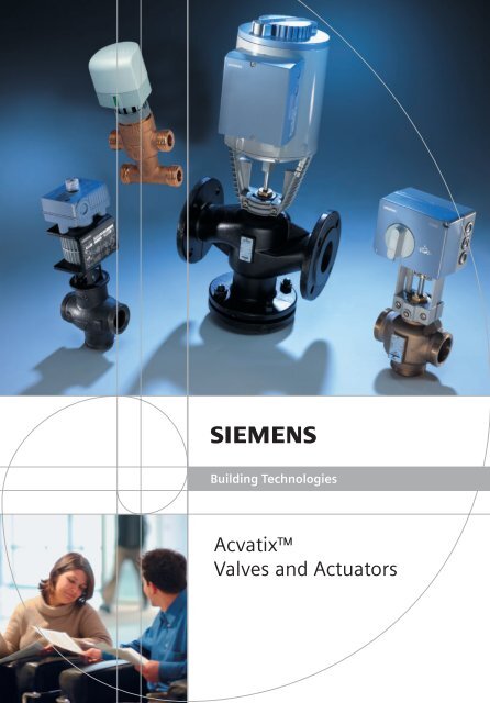
<strong>Building</strong> <strong>Technologies</strong><br />
Acvatix<br />
Valves and Actuators
Contents<br />
SKD, SQX, SKB, SKC<br />
V.G41, V.F21, V.F31, V.F40<br />
V.F41, VVF45, VVF52, V.F61<br />
SSC, SQS<br />
V.P45, V.G44, VVG55, VVI52<br />
MXG461, MXF461,<br />
MVF461H, MXG461B<br />
SQK, SQL<br />
VBF21, VBG31, VBI31, VCI31<br />
SQL, VKF41, VKF46<br />
SSA, SSB, STA, STP, SFA, RTN,<br />
V.P, V.I, V.S, VDN, VUN, VP.<br />
More than 50 engineers worldwide are working on the continual development<br />
of our comprehensive Acvatix range of valves and actuators on the<br />
forefront of technology, aimed at finding innovative solutions to satisfy<br />
the needs of our customers.<br />
Air conditioning, domestic hot water and heat pump plants as well as<br />
community and district heating systems are the major fields of use for our<br />
robust electromotoric and electrohydraulic actuators.<br />
For demanding applications, such as district heating systems and large<br />
plant in general, electrohydraulic actuators are the preferred choice.<br />
They are superior with large positioning forces, long-term reliability,<br />
spring return function and a host of auxiliary functions.<br />
The broad product range ensures the right valve for any type of application.<br />
Magnetic valves are especially suited for precise control of air conditioning<br />
plant. If fast-acting and exact control is of prime importance, e.g. air<br />
conditioning or domestic hot water, the precision valves with their magnetic<br />
actuators represent unique solutions. They are also highly suitable for<br />
special applications, such as test rigs in the industrial sector, precise air<br />
conditioning for clean rooms and critical manufacturing processes.<br />
Over the past few years, we have developed a large number of products<br />
for individual room temperature control. They are the ideal solutions for<br />
fan coil unit applications and chilled ceilings, underfloor heating and<br />
radiator systems.<br />
E.g. the pressure-compensated radiator valve for constant flow rate sets<br />
new standards.<br />
High-quality valves and actuators for central heating, ventilation and air<br />
conditioning plant<br />
Standard valves and actuators for central heating, ventilation and air conditioning<br />
plant<br />
High-precision valves for central heating, ventilation and air conditioning<br />
plant and special applications<br />
3-port / 4-port slipper valves and rotary actuators<br />
Butterfly valves and rotary actuators<br />
Small valves and actuators for individual room control<br />
2<br />
Pages 5 to 7<br />
Page 8<br />
Page 9<br />
Page 10<br />
Page 11<br />
Pages 12 to 15
3<br />
Generation Distribution Consumption<br />
: For product selection, refer to pages 5…9
Control valves and actuators for central HVAC plant<br />
Electrohydraulic line<br />
SKB, SKC, SKD<br />
• High positioning forces (up to 2800 N)<br />
• Long service life<br />
• Single seat, metallic sealing<br />
• Dirt-resistant<br />
• Low noise<br />
• Leakage rate < 0.02 % kvs • 3-port valves can be used as mixing<br />
or diverting valves<br />
• Long service life<br />
• Single seat, metallic sealing<br />
• Dirt-resistant<br />
• Low noise<br />
• Leakage rate < 0.02 % kvs • 3-port valves can be used as mixing<br />
or diverting valves<br />
High-quality valves and powerful actuators for<br />
the most demanding technical requirements<br />
and a long service life<br />
PN class Temperature Characteristic Spring return<br />
PN6 -25...220 °C Selectable: Available as<br />
PN10 350 °C Equal- per DIN<br />
PN16 (thermal oil) percentage 32730 if<br />
PN25 or linear required<br />
PN40<br />
Electromotoric line SQX Pages 5 to 7<br />
• Long service life<br />
• Single seat, metallic sealing<br />
• Dirt-resistant<br />
• Low noise<br />
• Leakage rate < 0.02 % kvs • 3-port valves can be used as mixing<br />
or diverting valves<br />
High-quality valves and actuators for the most<br />
demanding requirements<br />
PN class Temperature Characteristic Spring return<br />
PN16 -25...140 °C Selectable: None<br />
PN25 Equalpercentage<br />
or linear<br />
Electromotoric line SQS Page 8<br />
• Single seat, metallic sealing<br />
• Dirt-resistant<br />
• Low noise<br />
• Leakage rate < 0.02 % kvs High-quality valves and actuators for the most<br />
demanding requirements in smaller plant<br />
PN class Temperature Characteristic Spring return<br />
PN16 1...130 °C Selectable: Available as<br />
PN25 Equal- per DIN<br />
percentage 32 730 if<br />
or linear required<br />
Electromotoric line SSC Page 8<br />
Favorably priced valves and actuators for<br />
smaller plant<br />
PN class Temperature Characteristic Spring return<br />
PN16 1...110 °C Up to DN25: Available<br />
Equalpercentage,<br />
from DN25:<br />
Linear<br />
4<br />
Pages 5 to 7
Threaded 2- and 3-port valves with 20 mm stroke actuators<br />
Typical applications Type of actuator Stroke 20 mm 20 mm 20 mm<br />
Force 700 N 1000 N 2800 N<br />
• Heating zones, heat distribution<br />
• Primary heating and cooling plant<br />
• Ventilation and air conditioning Positioning time [s]<br />
• plants SQX<br />
Positioning<br />
signal<br />
Spring return<br />
function<br />
SKD<br />
SKB SQX SKD SKB<br />
3P – 150 120 120 SQX32.00 SKD32.50 SKB32.50<br />
AC 230 V 3P ✓SKD.. 35 30 SQX32.03 SKD32.21 –<br />
3P ✓ 120 120 – SKD32.51 SKB32.51<br />
0-10V – 35 30 120 SQX62 SKD60 SKB60<br />
0-10V ✓ 30 120 – SKD62 SKB62<br />
AC 24 V 3P – 150 120 120 SQX82.00 SKD82.50 SKB82.50<br />
3P – 35 SQX82.03 – –<br />
3P ✓ 120 120 – SKD82.51 SKB82.51<br />
Type ∆p s ∆p max ∆p s ∆p max ∆p s ∆p max<br />
Type of valve reference DN G [in] k vs [m 3 /h] [kPa] [kPa] [kPa] [kPa] [kPa] [kPa]<br />
PN16 VVG41.11...15 15 G 1B 0.63/1/1.6/2.5/4 1600 800 1600 800 1600 800<br />
VVG41 VVG41.20 20 G 1 1⁄4B 6,3 1600 800 1600 800 1600 800<br />
VVG41.25 25 G 1 1⁄2B 10 1550 800 1600 800 1600 800<br />
VVG41.32 32 G 2B 16 875 800 1275 800 1600 800<br />
VVG41.40 40 G 2 1⁄4B 25 525 525 775 775 1600 800<br />
– 25 ºC...130 ºC VVG41.50 50 G 2 3⁄4B 40 300 300 450 450 1225 800<br />
PN16 VXG41.13...15 15 G 1B 1.6/2.5/4 – 800 – 800 – 800<br />
VXG41 VXG41.20 20 G 1 1⁄4B 6,3 – 800 – 800 – 800<br />
VXG41.25 25 G 1 1⁄2B 10 – 800 – 800 – 800<br />
VXG41.32 32 G 2B 16 – 800 – 800 – 800<br />
VXG41.40 40 G 2 1⁄4B 25 – 525 – 775 – 800<br />
– 25 ºC...130 ºC VXG41.50 50 G 2 3⁄4B 40 – 300 – 450 – 800<br />
Union nuts for threaded valves ALG../ALS..<br />
R G<br />
R G<br />
R G<br />
Rp<br />
Rp<br />
G<br />
G<br />
– Valve side: Cylindric thread to ISO 228/1<br />
– Rp Pipe side: ALG... with cylindric G Rp- or tapered R-thread to ISO 7/1<br />
– Pipe side: ALS... with welded connection<br />
d G<br />
d G<br />
d G<br />
d G<br />
Union nuts: Made of brass or malleable cast iron<br />
Type reference 1) G [in] R, Rp [in] Material<br />
ALG13.. G 1/2 R 3/8B (externally threaded) Brass<br />
ALG14.. G 3/4 R 1/2B (externally threaded) Brass<br />
ALG12.. G 3/4 Rp 3/8 Malleable cast iron<br />
ALG15.. G 1 Rp 1/2 Malleable cast iron<br />
ALG20.. G 1 1/4 Rp 3/4 Malleable cast iron<br />
ALG25.. G 1 1/2 Rp 1 Malleable cast iron<br />
ALG32.. G 2 Rp 1 1/4 Malleable cast iron<br />
ALG40.. G 2 1/4 Rp 1 1/2 Malleable cast iron<br />
ALG50.. G 2 3/4 Rp 2 Malleable cast iron<br />
Union nuts: Made of steel, with welding connection<br />
Type reference 2) G [in] d [mm] Material<br />
ALS15 G 3/4 21.3 Steel, weldable<br />
ALS20 G 1 26.8 Steel, weldable<br />
ALS25 G 1 1/4 33.7 Steel, weldable<br />
1) ALG… union nuts are available in sets of 2 (ordering example: ALG252) or 3 (ALG253).<br />
d2) ALS… union nuts are Gavailable<br />
in sets of 2 (ordering example: ALS152).<br />
d G<br />
∆ps Maximum permissible differential pressure at which the motorized valve will close securely against the pressure (close off pressure)<br />
∆pmax Maximum permissible differential pressure across the valve’s control path, valid for the entire actuating range of the motorized valve<br />
(maximum recommended operating differential pressure)<br />
5
Flanged 3-port valves with 20 / 40 mm stroke actuators<br />
Typical applications Type of actuator Stroke 20 mm 20 mm 20 mm 40 mm<br />
Force 700 N 1000 N 2800 N 2800 N<br />
• Heating plant<br />
• Ventilation and air conditioning Positioning time [s]<br />
• plant SQX<br />
• Heat generation SKD<br />
• Heat distribution SKB SKB<br />
SKC SQX SKD SKC<br />
3P – 150 120 120 SQX32.00 SKD32.50 SKB32.50 SKC32.60<br />
AC 230 V 3P ✓SKD.. 35 30 SQX32.03 SKD32.21 – –<br />
3P ✓ 120 120 – SKD32.51 SKB32.51 SKC32.61<br />
0-10V – 35 30 120 SQX62 SKD60 SKB60 SKC60<br />
0-10V ✓ 30 120 – SKD62 SKB62 SKC62<br />
AC 24 V 3P – 120 120 SQX82.00 SKD82.50 SKB82.50 SKC82.60<br />
3P – SQX82.03 – – –<br />
3P ✓ 120 120 – SKD82.51 SKB82.51 SKC82.61<br />
Type ∆p max ∆p max ∆p max ∆p max<br />
Valves reference DN k vs [m 3 /h] [kPa] [kPa] [kPa] [kPa]<br />
PN6 VXF21.22...25 25 1.9/3/5/7.5 300 300 300 –<br />
VXF21 VXF21.39...40 40 12/19 300 300 300 –<br />
VXF21.50 50 31 300 300 300 –<br />
VXF21.65 65 49 175 275 300 –<br />
VXF21.80 80 78 100 175 300 –<br />
-25...130 ºC VXF21.90 100 124 – – – 200<br />
PN10 VXF31.24...25 25 5/7.5 300 300 300 –<br />
VXF31 VXF31.39...40 40 12/19 300 300 300 –<br />
VXF31.50 50 31 300 300 300 –<br />
VXF31.65 65 49 175 275 300 –<br />
VXF31.80 80 78 100 175 300 –<br />
VXF31.90 100 124 – – – 200<br />
VXF31.91 125 200 – – – 150<br />
-25...130 ºC VXF31.92 150 300 – – – 100<br />
PN16 VXF40.15-... 15 1.9/3 300 300 300 –<br />
VXF40 VXF40.25-5 25 5 300 300 300 –<br />
VXF40.25-7.5 25 7.5 300 300 300 –<br />
VXF40.40-12 40 12 300 300 300 –<br />
VXF40.40-19 40 19 300 300 300 –<br />
VXF40.50-31 50 31 300 300 300 –<br />
VXF40.65-49 65 49 175 275 300 –<br />
VXF40.80-78 80 78 100 175 300 –<br />
VXF40.100-124 100 124 – – – 200<br />
VXF40.125-200 125 200 – – – 150<br />
-25...130 ºC VXF40.150-300 150 300 – – – 100<br />
PN16 VXF41.14...15 15 1.9/3 800 800 800 –<br />
VXF41 VXF41.24 25 5 800 800 800 –<br />
VXF41.25 25 7.5 800 800 800 –<br />
VXF41.39 40 12 500 750 800 –<br />
VXF41.40 40 19 500 750 800 –<br />
VXF41.49 50 19 350 500 800 –<br />
VXF41.50 50 31 350 500 800 –<br />
VXF41.65 65 49 – – – 500<br />
VXF41.80 80 78 – – – 350<br />
VXF41.90 100 124 – – – 250<br />
VXF41.91 125 200 – – – 175<br />
-25...130 ºC (180 °C) VXF41.92 150 300 – – – 100<br />
PN40 VXF61.14...15 15 1.9/3 – 1200 1600 –<br />
VXF61 VXF61.24...25 25 5/7.5 – 1200 1600 –<br />
VXF61.39...40 40 12/19 – – 1200 –<br />
VXF61.50 50 31 – – 1000 –<br />
VXF61.65 65 49 – – – 800<br />
VXF61.80 80 78 – – – 500<br />
VXF61.90 100 124 – – – 300<br />
VXF61.91 125 200 – – – 200<br />
-25...220 ºC (350 °C) VXF61.92 150 300 – – – 100<br />
∆p s Maximum permissible differential pressure at which the motorized valve will close securely against the pressure (close off pressure)<br />
∆p max Maximum permissible differential pressure across the valve’s control path, valid for the entire actuating range of the motorized valve<br />
(maximum recommended operating differential pressure)<br />
6<br />
Positioning<br />
signal<br />
Spring return<br />
function
Flanged 2-port valves with 20 / 40 mm stroke actuators<br />
Typical applications Type of actuator Stroke 20 mm 20 mm 20 mm 40 mm<br />
Force 700 N 1000 N 2800 N 2800 N<br />
• Heating plant<br />
• Ventilation and air conditioning Positioning time [s]<br />
• plant SQX<br />
• Heat generation SKD<br />
Positioning<br />
signal<br />
Spring return<br />
function<br />
• Heat distribution SKB SKB<br />
• District heating plant<br />
SKC SQX SKD SKC<br />
3P – 150 120 120 SQX32.00 SKD32.50 SKB32.50 SKC32.60<br />
AC 230 V 3P ✓SKD..– 35 30 SQX32.03 SKD32.21 – –<br />
3P ✓ 120 120 – SKD32.51 SKB32.51 SKC32.61<br />
0-10V – 35 30 120 SQX62 SKD60 SKB60 SKC60<br />
0-10V ✓ 30 120 – SKD62 SKB62 SKC62<br />
AC 24 V 3P – 120 120 SQX82.00 SKD82.50 SKB82.50 SKC82.60<br />
3P – SQX82.03 – – –<br />
3P ✓ 120 120 – SKD82.51 SKB82.51 SKC82.61<br />
Type ∆p s ∆p max ∆p s ∆p max ∆p s ∆p max ∆p s ∆p max<br />
Valves reference DN k vs [m 3 /h] [kPa] [kPa] [kPa] [kPa] [kPa] [kPa] [kPa] [kPa]<br />
PN6 VVF21.22...25 25 1.9/3/5/7.5 600 300 600 300 600 300 – –<br />
VVF21 VVF21.39...40 40 12/19 500 300 600 300 600 300 – –<br />
VVF21.50 50 31 300 300 450 300 600 300 – –<br />
VVF21.65 65 49 175 175 275 275 600 300 – –<br />
VVF21.80 80 78 100 100 175 175 500 300 – –<br />
-25...130 ºC VVF21.90 100 124 – – – – – – 300 200<br />
PN10 VVF31.24...25 25 5/7.5 1000 300 1000 300 1000 300 – –<br />
VVF31 VVF31.39...40 40 12/19 525 300 775 300 1000 300 – –<br />
VVF31.50 50 31 325 300 475 300 1000 300 – –<br />
VVF31.65 65 49 175 175 275 275 750 300 – –<br />
VVF31.80 80 78 100 100 175 175 500 300 – –<br />
VVF31.90 100 124 – – – – – – 300 200<br />
VVF31.91 125 200 – – – – – – 200 150<br />
-25...130 ºC VVF31.92 150 300 – – – – – – 125 100<br />
PN16 VVF40.15-... 15 1.9/3 1600 300 1600 300 1600 300 – –<br />
VVF40 VVF40.25-... 25 5/7.5 1550 300 1600 300 1600 300 – –<br />
VVF40.40-... 40 12/19 525 300 775 300 1600 300 – –<br />
VVF40.50-31 50 31 325 300 475 300 1300 300 – –<br />
VVF40.65-49 65 49 175 175 275 275 750 300 – –<br />
VVF40.80-78 80 78 100 100 175 175 500 300 – –<br />
VVF40.100-124 100 124 – – – – – – 300 200<br />
VVF40.125-200 125 200 – – – – – – 200 150<br />
-25...130 ºC VVF40.150-300 150 300 – – – – – – 125 100<br />
PN16 VVF41.49...50 50 19/31 350 300 500 400 1400 1000 – –<br />
VVF41 VVF41.65 65 49 – – – – – – 800 600<br />
VVF41.80 80 78 – – – – – – 500 400<br />
VVF41.90 100 124 – – – – – – 300 250<br />
VVF41.91 125 200 – – – – – – 200 175<br />
-25...130 ºC (180 °C) VVF41.92 150 300 – – – – – – 125 100<br />
PN16 VVF45.49...50 50 19/31 – – – – 1600 1200 – –<br />
VVF45 VVF45.65 65 49 – – – – – – 1600 1000<br />
VVF45.80 80 78 – – – – – – 1600 700<br />
VVF45.90 100 124 – – – – – – 1600 450<br />
VVF45.91 125 200 – – – – – – 1600 300<br />
-25...140 ºC (180 °C) VVF45.92 150 300 – – – – – – 1600 200<br />
PN25 VVF52.15-... 15 0.16/0.2/0.25/0.32 2500 1600 2500 1600 2500 1600 – –<br />
VVF52 VVF52.15-... 15 0.4/0.5/0.63/0.8/1 2500 1600 2500 1600 2500 1600 – –<br />
VVF52.15-... 15 1.25/1.6/2/2.5/3.2/4 2500 1600 2500 1600 2500 1600 – –<br />
VVF52.25-... 25 5/6.3/8/10 1500 1200 2250 1600 2500 1600 – –<br />
-25...140 ºC (180 °C) VVF52.40-... 40 12.5/16/20/25 500 400 750 700 2000 1600 – –<br />
PN40 VVF61.09...12 15 0.19/0.3/0.45/0.7 – – 4000 1600 4000 1600 – –<br />
VVF61 VVF61.13...15 15 1.2/1.9/3 – – 4000 1600 4000 1600 – –<br />
VVF61.23...25 25 3/5/7.5 – – 2250 1600 4000 1600 – –<br />
VVF61.39...40 40 12/19 – – – – 4000 1600 – –<br />
VVF61.50 50 31 – – – – 4000 1600 – –<br />
VVF61.65 65 49 – – – – – – 4000 1000<br />
VVF61.80 80 78 – – – – – – 4000 700<br />
VVF61.90 100 124 – – – – – – 4000 450<br />
VVF61.91 125 200 – – – – – – 4000 300<br />
-25...220 ºC (350 °C) VVF61.92 150 300 – – – – – – 4000 200<br />
7
Threaded 2-port and 3-port valves<br />
with 5.5 mm stroke actuators 400 N<br />
Typical applications Type of actuator Stroke 5.5 mm<br />
Force 400 N<br />
• Heating plant<br />
• District heating plant SQS Positioning time<br />
• Ventilation and air conditioning [s]<br />
• plant<br />
SQS35..<br />
Threaded 2-port and 3-port valves with 5.5 mm stroke actuators 300 N<br />
8<br />
Positioning<br />
signal<br />
SQS35.. SQS65..<br />
SQS85.. SQS85..<br />
AC 230 V 3P ✓ 150 35 SQS35.50 SQS35.53 –<br />
3P – 150 35 – SQS35.00 SQS35.03<br />
3P – 150 35 – SQS85.00 SQS85.03<br />
0-10V – – 35 – – SQS65<br />
AC 24 V 0-10V ✓ – 35 SQS65.5 – –<br />
2-10V – – 35 – – SQS65.2<br />
Type ∆p s ∆p max ∆p s ∆p max ∆p s ∆p max<br />
Valves reference DN G [in] k vs [m 3 /h] [kPa] [kPa] [kPa] [kPa] [kPa] [kPa]<br />
PN16 VVG44.15-... 15 G 1B 0.25 / 0.4 / 0.63 1600 400 1600 400 1600 400<br />
VVG44 VVG44.15-... 15 G 1B 1 / 1.6 725 400 725 400 725 400<br />
VVG44.15-... 15 G 1B 2.5 / 4 350 400 350 400 350 400<br />
VVG44.20-6.3 20 G 1 1/4B 6.3 750 400 750 400 750 400<br />
VVG44.25-10 25 G 1 1/2B 10 450 400 450 400 450 400<br />
VVG44.32-16 32 G 2B 16 250 250 250 250 250 250<br />
1...120 °C VVG44.40-25 40 G 2 1/4B 25 125 125 125 125 125 125<br />
PN16 VXG44.15-... 15 G 1B 0.25 / 0.4 / 0.63 – 400 – 400 – 400<br />
VXG44 VXG44.15-... 15 G 1B 1 / 1.6 – 400 – 400 – 400<br />
VXG44.15-... 15 G 1B 2.5 / 4 – 400 – 400 – 400<br />
VXG44.20-6.3 20 G 1 1/4B 6.3 – 400 – 400 – 400<br />
VXG44.25-10 25 G 1 1/2B 10 – 400 – 400 – 400<br />
VXG44.32-16 32 G 2B 16 – 250 – 250 – 250<br />
1...120 °C VXG44.40-25 40 G 2 1/4B 25 – 125 – 125 – 125<br />
PN25 VVG55.15-... 15 G 3/4B 0.25 / 0.4 2500 1200 2500 1200 2500 1200<br />
VVG55 VVG55.15-... 15 G 3/4B 0.63 2500 1200 2500 1200 2500 1200<br />
VVG55.15-... 15 G 3/4B 1 / 1.6 2300 1200 2300 1200 2300 1200<br />
VVG55.15-... 15 G 3/4B 2.5 2300 1200 2300 1200 2300 1200<br />
VVG55.20-4 20 G 1B 4 1000 1000 1000 1000 1000 1000<br />
1...130 °C VVG55.25-6.3 25 G 1 1/4B 6.3 800 800 800 800 800 800<br />
Typical applications Type of actuator Stroke 5.5 mm<br />
Force 300 N<br />
• Heating plant<br />
• Ventilation plant SSC Positioning time<br />
[s]<br />
Positioning<br />
signal<br />
Spring return<br />
function<br />
Spring return<br />
function<br />
SSC31<br />
SSC81 SSC61<br />
AC 230 V 3P – 150 SSC31<br />
3P – 150 SSC81<br />
AC 24 V 0-10V – 30 SSC61<br />
0-10V ✓ 30 SSC61.5<br />
Type ∆p s ∆p max ∆p s ∆p max ∆p s ∆p max<br />
Valves reference DN G [in] k vs [m 3 /h] [kPa] [kPa] [kPa] [kPa] [kPa] [kPa]<br />
PN16 VVP45.20-4 20 G 1B 4 350 350 350 350 350 350<br />
VVP45 VVP45.25-6,3 25 G 1 1/4B 6.3 300 300 300 300 300 300<br />
VVP45.25-10 25 G 1 1/2B 10 300 300 300 300 300 300<br />
VVP45.32-16 32 G 2B 16 175 175 175 175 175 175<br />
1...110 °C VVP45.40-25 40 G 2 1/4B 25 75 75 75 75 75 75<br />
PN16 VXP45.20-4 20 G 1B 4 – 350 – 350 – 350<br />
VXP45 VXP45.25-6,3 25 G 1 1/4B 6.3 – 300 – 300 – 300<br />
VXP45.25-10 25 G 1 1/2B 10 – 300 – 300 – 300<br />
VXP45.32-16 32 G 2B 16 – 175 – 175 – 175<br />
1...110 °C VXP45.40-25 40 G 2 1/4B 25 – 75 – 75 – 75<br />
Note: For DN10...DN15 with k vs = 0.25...2.5 m 3 /h, VVP45... and VXP45... valves can be used (refer to page 12)
Magnetic valves for central HVAC plant<br />
Magnetic line<br />
• Positioning time < 2 s<br />
• Stroke resolution 1 : 1000<br />
• No wear and tear<br />
• Leakage rate < 0.02 % kvs High-precision and fast-acting combinations of<br />
valves and actuators<br />
PN class Temperature Characteristic Spring return<br />
PN16 -20...180 °C Selectable: Standard<br />
Equalpercentage<br />
or linear<br />
Threaded / flanged 2-port and 3-port valves with integrated magnetic actuator<br />
Typical applications Standard range Range for special application<br />
• Supply air control with / without cascade MXG461 M…P for media containing minerals<br />
• Fast-acting heat exchanger control MXF461, M3P...FY M…S with valve body made of stainless cast steel<br />
• DHW mixing control MXG461B... M…M silicon-free version<br />
• High-precision process control MVF461H...<br />
Key features of the magnetic line<br />
• Short positioning times ➞ fast response to disturbance variables<br />
• High stroke resolution ➞ excellent control performance<br />
• No abrupt start ➞ control stability also in the low-load range<br />
• Modulating magnetic actuators with no wear and tear ➞ long service life<br />
Combinations<br />
Type<br />
reference DN G [in] kvs [m<br />
1)<br />
∆ps ∆pmax Actuator AC 24 V<br />
Note: To be used as 2-port or mixing valves, not as diverting valves. When used as 2-port valves, the bypass is to be closed off with a blanking flange and screws<br />
1) Only for use as 2-port valves<br />
3 PN16 MXG461.15... 15 G 1B<br />
/h]<br />
0.6/1.5/3.0 300<br />
[kPa]<br />
300<br />
[kPa]<br />
300<br />
Positioning signal<br />
DC 0...10 V<br />
MXG461 MXG461.20-5.0 20 G 1 1/4B 5 300 300 or<br />
MXG461.25-8.0 25 G 1 1/2B 8 300 300 DC 2...10 V<br />
MXG461.32-12 32 G 2B 12 300 300 or<br />
MXG461.40-20 40 G 2 1/4B 20 300 300 DC 4...20 mA<br />
1...120 °C MXG461.50-30 50 G 2 3/4B 30 300 300<br />
PN16 MXF461.15... 15 – 0.6/1.5/3 300 300 300 DC 0...10 V<br />
MXF461 MXF461.20-5.0 20 – 5 300 300 or<br />
MXF461.25-8.0 25 – 8 300 300 DC 2...10 V<br />
MXF461.32-12 32 – 12 300 300 or<br />
MXF461.40-20 40 – 20 300 300 DC 4...20 mA<br />
MXF461.50-30 50 – 30 300 300<br />
MXF461.65-50 65 – 50 300 300<br />
M3P80FY 80 – 80 300 300 DC 0...10 V or<br />
1...120 °C M3P100FY 100 – 130 200 200 DC 4...20 mA<br />
Threaded 3-port valves for domestic hot water<br />
Combinations<br />
Type<br />
reference DN G [in] kvs [m<br />
1)<br />
∆ps ∆pmax Actuator AC 24 V<br />
3 PN16 MXG461B15-0.6 08/15 G 1B<br />
/h]<br />
0.6<br />
[kPa]<br />
1000<br />
[kPa]<br />
1000<br />
Positioning signal<br />
DC 0...10 V<br />
MXG461B MXG461B15-1.5 08/15 G 1B 1.5 1000 1000 or<br />
MXG461B15-3 15 G 1B 3 1000 1000 DC 2...10 V<br />
MXG461B20-5 20 G 1 1/4B 5 800 800 or<br />
MXG461B25-8 25 G 1 1/2B 8 700 700 DC 0...20 mA<br />
MXG461B32-12 32 G 2B 12 600 600 or<br />
MXG461B40-20 40 G 2 1/4B 20 600 600 DC 4...20 mA<br />
-20...120 °C MXG461B50-30 50 G 2 3/4B 30 600 600<br />
Flanged 2-port valves for district heating plant<br />
Type ∆p s ∆p max Actuator AC 24 V -<br />
Combinations reference DN k vs [m 3 /h] [kPa] [kPa] Positioning signal<br />
PN16 MVF461H15-0.6 15 0.6 1000 1000 DC 0...10 V<br />
MVF461H MVF461H15-1.5 15 1.5 1000 1000 or<br />
MVF461H15-3 15 3 1000 1000 DC 2...10 V<br />
MVF461H20-5 20 5 1000 1000 or<br />
MVF461H25-8 25 8 1000 1000 DC 0...20 mA<br />
MVF461H32-12 32 12 1000 1000 or<br />
MVF461H40-20 40 20 1000 1000 DC 4...20 mA<br />
1...180 °C MVF461H50-30 50 30 1000 1000<br />
9
3-port and 4-port slipper valves for heating plant<br />
3- and 4-port<br />
slipper valves<br />
• Direct coupled (SQK34)<br />
• Long service life<br />
• Low noise<br />
• Maintenance-free<br />
• Linear characteristic<br />
• Size 20...50 with manual adjuster<br />
• Flexibility: Actuator can be mounted in 4<br />
different positions<br />
Typical applications<br />
• Small to medium-size heating plant<br />
Type of actuator Torque 5 Nm 5 Nm 10/12.5 Nm<br />
• Closed circuits SQK Positioning Positioning<br />
SQL signal time [s]<br />
SQK33 SQL33<br />
SQK34 SQL33<br />
SQK84 SQL83<br />
AC 230 V 3-position 125 30 SQK33.00 SQL33.03<br />
3-position 135 125 SQK34.00 SQL33.00<br />
AC 24 V 3-position 135 SQK84.00<br />
10<br />
High-quality slipper valves and powerful actuators for the<br />
most demanding requirements and a long service life<br />
Rotary actuators SQK... and SQL...<br />
Positioning signal Torque [Nm] Positioning time [s]<br />
3P/AC 230 V 5, 10, 12.5 125; 30<br />
3P/AC 24 V<br />
3-port / 4-port slipper valves VB... and VC...<br />
PN class k vs [m 3 /h] Temperature Leakage rate<br />
PN6 6.3...820 1...120 °C Up to DN100:<br />
PN10 < 0.1% k vs<br />
from DN125:<br />
< 0.5% k vs<br />
3-port and 4-port slipper valves with rotary actuators 5 Nm / 12.5 Nm<br />
3-position 125 SQL83.00<br />
Mounting kits – ASK32 ASK31<br />
3-port slipper valves, ∆p max ∆p max ∆p max<br />
flanged Type DN k vs [m 3 /h] [kPa] [kPa] [kPa]<br />
PN6 VBF21.40 40 25 30 30 –<br />
VBF21 VBF21.50 50 40 30 30 –<br />
VBF21.65 65 63 – – 30<br />
VBF21.80 80 100 – – 30<br />
VBF21.100 100 160 – – 30<br />
VBF21.125 125 500 – – 30<br />
1...120 °C VBF21.150 150 820 – – 30<br />
3-port slipper valves, ∆p max ∆p max ∆p max<br />
externally or internally threaded Type DN G [in] k vs [m 3 /h] [kPa] [kPa] [kPa]<br />
PN10 VBG31.20 20 G 1 1/4B 6.3 30 30 –<br />
VBG31 VBG31.25 25 G 1 1/2B 10 30 30 –<br />
VBG31.32 32 G 2B 16 30 30 –<br />
1...120 °C VBG31.40 40 G 2 1/4B 25 30 30 –<br />
PN10 VBI31.20 20 Rp 3/4 6.3 30 30 –<br />
VBI31 VBI31.25 25 Rp 1 10 30 30 –<br />
VBI31.32 32 Rp 1 1/4 16 30 30 –<br />
1...120 °C VBI31.40 40 Rp 1 1/2 25 30 30 –<br />
4-port slipper valves, ∆p max ∆p max ∆p max<br />
internally threaded Type DN G [in] k vs [m 3 /h] [kPa] [kPa] [kPa]<br />
PN10 VCI31.20 20 Rp 3/4 6.3 30 30 –<br />
VCI31 VCI31.25 25 Rp 1 10 30 30 –<br />
VCI31.32 32 Rp 1 1/4 16 30 30 –<br />
1...120 °C VCI31.40 40 Rp 1 1/2 25 30 30 –
Butterfly valves for central HVAC plant<br />
Butterfly valves<br />
• Great rotary forces<br />
• Direct coupled<br />
• Long service life<br />
• Low noise<br />
• Maintenance-free<br />
• Air bubble-tight to DIN 3230<br />
High-quality butterfly valves and powerful actuators<br />
for the most demanding requirements and a long<br />
service life<br />
Rotary actuators SQL...<br />
Positioning signal Torque [Nm] Positioning time [s]<br />
3P/AC 230 V 10, 12.5, 20, 6, 12, 30, 125<br />
3P/AC 24 V 100, 400<br />
Butterfly valves VKF41 and VKF46<br />
PN class Temperature k vs [m 3 /h] Leakage rate<br />
PN6 -15...120 °C 50...14500 VKF41:0.22...<br />
PN10<br />
PN16<br />
0.01% of kVS<br />
VKF46: Air<br />
bubble-tight<br />
Butterfly valves for mounting between flanges,<br />
with rotary actuators 10 to 400 Nm<br />
Type of<br />
Typical applications actuator Torque 10/12.5 Nm 20 Nm 20 Nm 100 Nm 400 Nm<br />
• Shut off or control 3-position<br />
• For closed or open loop HVAC plant Positioning<br />
SQL33, 83 time [s]<br />
SQL35, 85 SQL33<br />
SQL36 SQL35 SQL33<br />
SQL83 SQL36<br />
SQL85 SQL36<br />
30 125 SQL33.03 SQL35.00<br />
AC 230 V 125 61) SQL33.00 SQL36E65<br />
125 121) SQL35.00 SQL36E110<br />
AC 24 V 125 SQL83.00 SQL85.00 SQL85.00 – –<br />
Mounting kits ASK33 ASK35.1 ASK35.2 – –<br />
1) With auxiliary module SEZ31: Variable positioning time 30…180 s (SQL36E65) or 60…360 s (SQL36E110)<br />
Type ∆p max ∆p max ∆p max ∆p max ∆p max<br />
Butterfly valves reference DN k vs [m 3 /h] [kPa] [kPa] [kPa] [kPa] [kPa]<br />
PN16 VKF41.40 40 50 500 – – – –<br />
VKF41 VKF41.50 50 80 500 – – – –<br />
VKF41.65 65 200 500 – – – –<br />
VKF41.80 80 400 500 – – – –<br />
VKF41.100 100 760 500 – – – –<br />
VKF41.125 125 1000 300 – – – –<br />
VKF41.150 150 2100 250 – – – –<br />
-15...120 °C VKF41.200 200 4000 125 – – – –<br />
PN16 VKF46.40 40 50 – 1600 – – –<br />
VKF46 VKF46.50 50 80 – 1600 – – –<br />
VKF46.65 65 200 – 1600 – – –<br />
VKF46.80 80 400 – – 1600 – –<br />
VKF46.100 100 760 – – 1000 – –<br />
VKF46.125 125 1000 – – 800 – –<br />
VKF46.150 150 2100 – – – 1200 –<br />
VKF46.200 200 4000 – – – 400 –<br />
VKF46.250 250 6400 – – – – 1000<br />
VKF46.300 300 8500 – – – – 600<br />
VKF46.350 350 11500 – – – – 300<br />
-15...120 °C VKF46.400 400 14500 – – – – 200<br />
11
Control valves and actuators for room and zone applications<br />
Small electromotoric<br />
valves 200 N<br />
• Automatic detection of valve stroke<br />
• Long service life<br />
• Low noise<br />
• Plug-in connecting cable<br />
For high pressure differentials<br />
• Long service life<br />
• Single seat, metallic sealing<br />
• Dirt-resistant<br />
• Low noise<br />
• Leakage rate < 0.02 % k vs<br />
12<br />
High-quality actuators for the most demanding<br />
requirements<br />
Electromotoric actuators SSB<br />
Positioning signal Positioning force [N] Stroke [mm]<br />
3-position/AC 230 V 200 5.5<br />
3-position/AC 24 V<br />
DC 0-10 V/AC 24 V<br />
Small valves VMP43... and V.P45...<br />
PN class k vs [m 3 /h] Temperature Characteristic<br />
PN16 0.25...6.3 1...110 °C Equalpercentage<br />
Small 2-port and 3-port valves with 5.5 mm stroke actuators 200 N<br />
Typical applications Type of actuators Stroke 5.5 mm<br />
Force 200 N<br />
• Terminal units<br />
• Induction units SSB<br />
• Chilled ceilings Positioning<br />
time [s]<br />
Positioning<br />
signal<br />
Spring return<br />
function<br />
SSB31<br />
SSB81 SSB61<br />
AC 230 V 3P – 150 – SSB31<br />
3P ✓ 150 – SSB31.1<br />
3P – 150 – SSB81<br />
AC 24 V 3P ✓ 150 – SSB81.1<br />
0..10V – – 75 SSB61<br />
Type ∆p s ∆p max ∆p s ∆p max ∆p s ∆p max<br />
Valves reference DN G [in] k vs [m 3 /h] [kPa] [kPa] [kPa] [kPa] [kPa] [kPa]<br />
PN16 VVP45.10 1) 10 G 1/2B 0.25 / 0.4 / 0.63 725 400 725 400 725 400<br />
VVP45 VVP45.10 1) 10 G 1/2B 1 / 1.6 725 400 725 400 725 400<br />
VVP45.15 1) 15 G 3/4B 2.5 350 350 350 350 350 350<br />
VVP45.20 1) 20 G 1B 4 350 350 350 350 350 350<br />
1...110 °C VVP45.25 1) 25 G 1 1/4B 6.3 300 300 300 300 300 300<br />
PN16 VXP45.10 1) 10 G 1/2B 0.25 / 0.4 / 0.63 – 400 – 400 – 400<br />
VXP45 VXP45.10 1) 10 G 1/2B 1 / 1.6 – 400 – 400 – 400<br />
VXP45.15 1) 15 G 3/4B 2.5 – 350 – 350 – 350<br />
VXP45.20 1) 20 G 1B 4 – 350 – 350 – 350<br />
1...110 °C VXP45.25 1) 25 G 1 1/4B 6.3 – 300 – 300 – 300<br />
PN16 VMP45.10 1) 10 G 1/2B 0.25 / 0.4 – 400 – 400 – 400<br />
VMP45 VMP45.10 1) 10 G 1/2B 0.63 / 1 – 400 – 400 – 400<br />
VMP45.10 1) 10 G 1/2B 1.6 – 400 – 400 – 400<br />
VMP45.15 1) 15 G 3/4B 2.5 – 350 – 350 – 350<br />
1...110 °C VMP45.20 1) 20 G 1B 4 – 350 – 350 – 350<br />
1) The complete type reference also contains the kvs value, e.g. VVP45.10-0,25<br />
∆p s Maximum permissible differential pressure at which the motorized valve will close securely against the pressure (close off pressure)<br />
∆p max Maximum permissible differential pressure across the valve’s control path, valid for the entire actuating range of the motorized valve<br />
(maximum recommended operating differential pressure).
Control valves and actuators for room and zone applications<br />
Small electromotoric and<br />
thermal valves 100 N<br />
Cost-effective 2-position actuators<br />
• Noiseless<br />
• Long service life<br />
• Overload-resistant and anti-locking<br />
• Long service life<br />
• 1.8 m connecting cable<br />
• Manual adjustment, spring return<br />
• Auxiliary switch (optional)<br />
• Automatic detection of valve stroke<br />
• Long service life<br />
• Low noise<br />
• Plug-in connecting cable<br />
Cost-effective valves for standard applications<br />
• Long service life<br />
• Single seat, metallic sealing<br />
• Dirt-resistant<br />
• Low noise<br />
• Leakage rate < 0.05% k vs<br />
High-quality actuators for<br />
demanding requirements<br />
Thermal actuators STP, STS<br />
Positioning signal Positioning force [N] Stroke [mm]<br />
2-position/AC 230 V 100 2.5<br />
2-position/AC 24 V<br />
DC 0-10 V/AC 24 V<br />
Electromotive actuators SFP<br />
Positioning signal Positioning force [N] Stroke [mm]<br />
2-position/AC 230 V 100 2.5<br />
2-position/AC 24 V<br />
Electromotive actuators SFP<br />
Positioning signal Positioning force [N] Stroke [mm]<br />
3-position/AC 230 V 100 2.5<br />
3-position/AC 24 V<br />
DC 0-10 V/AC 24 V<br />
Small valves VVP47..., VXP47 and VMP47...<br />
PN class kVS [m 3 /h] Temperature Characteristic<br />
PN16 0.25...4 1...110 °C Linear<br />
Small 2-port and 3-port valves with 2.5 mm stroke actuators 100 N<br />
Typical applications Type of Stroke 2.5 mm<br />
actuator Force 100 N<br />
• Terminal units STP Positioning Positioning<br />
• Induction units SFP signal time [s]<br />
• Chilled ceilings SSP STP STP<br />
STS SFP SFP<br />
SSP SSP<br />
STS<br />
AC 230 V 2P – 180 STP21<br />
2P – 35 SFP21<br />
3P – 150 SSP31<br />
AC 24 V 2P 180 STP71<br />
2P 35 SFP71<br />
3P 150 43 SSP81 SSP81.04<br />
AC/DC 24 V 0...10 V 150 34 STS61 SSP61<br />
5…7.5 V – 34 SSP61.P<br />
Type ∆p s ∆p max ∆p s ∆p max<br />
Valves reference DN G [in] k vs [m 3 /h] [kPa] [kPa] [kPa] [kPa]<br />
PN16 VVP47.10 1) 10 G 1/2B 0.25 / 0.4 700 400 1000 400<br />
VVP47 VVP47.10 1) 10 G 1/2B 0.63 / 0.1 250 250 500 400<br />
VVP47.10 1) 10 G 1/2B 1.6 150 150 300 300<br />
VVP47.15 1) 15 G 3/4B 2.5 150 150 300 300<br />
1...110 °C VVP47.20 1) 20 G 1B 4 100 100 175 175<br />
PN16 VXP47.10 1) 10 G 1/2B 0.25 / 0.4 – 400 – 400<br />
VXP47 VXP47.10 1) 10 G 1/2B 0.63 / 1 – 250 – 400<br />
VXP47.10 1) 10 G 1/2B 1.6 – 150 – 300<br />
VXP47.15 1) 15 G 3/4B 2.5 – 150 – 300<br />
1...110 °C VXP47.20 1) 20 G 1B 4 – 100 – 175<br />
PN16 VMP47.10 1) 10 G 1/2B 0.25 / 0.4 – 400 – 400<br />
VMP47 VMP47.10 1) 10 G 1/2B 0.63 / 1 – 250 – 400<br />
VMP47.10 1) 10 G 1/2B 1.6 – 150 – 300<br />
1...110 °C VMP47.15 1) 15 G 1/2B 2.5 – 150 – 300<br />
1) The complete type reference also contains the kvs value, e.g. VVP47.10-0.63<br />
Valves with connections for CONEX compression fittings for use with copper pipes carry type suffix …S<br />
(e.g. VVP47.10–0.25S), for nominal sizes DN10 and DN15.<br />
13
Control valves and actuators for zone applications<br />
On / off line<br />
• Overload-resistant and anti-locking<br />
• Long service life<br />
• 1.8 m connecting cable<br />
• Manual adjustment, spring return<br />
• Auxiliary switch (optional)<br />
• Long service life<br />
• Single seat, metallic sealing<br />
• Dirt-resistant<br />
• Low noise<br />
• Threaded or solder connections<br />
14<br />
High-quality valves and<br />
actuators for on / off control<br />
Motoric actuators SFA<br />
Positioning signal Positioning force [N] Stroke [mm]<br />
2-position/AC 230 V 100 2.5<br />
2-position/AC 24 V<br />
Zone valves V..46<br />
PN class kVS [m 3 /h] Temperature<br />
PN16 2..5 1...110 °C<br />
2-port and 3-port zone valves with 2.5 mm stroke actuators 100 N<br />
Typical applications Type of Stroke 2.5 mm<br />
actuator Force 100 N<br />
• Terminal units<br />
• DHW storage tank charging SFA<br />
• Zone control<br />
Positioning<br />
signal<br />
Positioning<br />
time [s]<br />
AC 230 V 2P 30-50 SFA 21/18<br />
AC 24 V 2P 30-50 SFA 71/18<br />
Type ∆p s ∆p max ∆p s ∆p max<br />
Valves with threaded connections reference DN G [in] k vs [m 3 /h] [kPa] [kPa] [kPa] [kPa]<br />
PN16 VVI46.15 15 Rp 1/2 2 300 300 300 300<br />
VVI46 VVI46.20 20 Rp 3/4 3.5 300 300 300 300<br />
VVI46.25 25 Rp 1 5 300 300 300 300<br />
1...110 °C<br />
PN16 VXI46.15 15 Rp 1/2 2 – 300 – 300<br />
VXI46 VXI46.20 20 Rp 3/4 3.5 – 300 – 300<br />
VXI46.25 25 Rp 1 5 – 300 – 300<br />
1...110 °C<br />
Typ Inside dia- k vs ∆p s ∆p max ∆p s ∆p max<br />
Valves with solder connections reference DN meter [mm] [m 3 /h] [kPa] [kPa] [kPa] [kPa]<br />
PN16 VVS46.15 15 16.0 2 300 300 300 300<br />
VVS46 VVS46.20 20 22.37 3.5 300 300 300 300<br />
VVS46.25 25 28.75 5 300 300 300 300<br />
1...110 °C<br />
PN16 VXS46.15 15 16.0 2 – 300 – 300<br />
VXS46 VXS46.20 20 22.37 3.5 – 300 – 300<br />
VXS46.25 25 28.75 5 – 300 – 300<br />
1...110 °C<br />
In the case of 3-port valves, the ∆p max values apply to the «diverting» function.<br />
For noiseless operation and for the «mixing» function, the value of 100 kPa should not be exceeded.<br />
∆p s Maximum permissible differential pressure at which the motorized valve will close securely against the pressure (close off pressure)<br />
∆p max Maximum permissible differential pressure across the valve’s control path, valid for the entire actuating range of the motorized valve<br />
(maximum recommended operating differential pressure)
Control valves and actuators for room applications<br />
TRV / MCV line<br />
Motoric actuators SSA...<br />
• Automatic detection of valve stroke<br />
• Low noise<br />
• Plug-in connecting cable<br />
Thermal actuators STA..., STS<br />
• Noiseless<br />
Thermostatic actuators RTN...<br />
• Noiseless<br />
• Fully closed thermostatic head for<br />
demanding hygienic requirements<br />
• With setpoint limitation<br />
• Manual setpoint adjustment<br />
Radiator valves VDN, VEN and VUN<br />
• Tested to EN 215<br />
• Insert can be replaced while plant is<br />
under pressure<br />
Pressure-compensated radiator valves<br />
VP... (MCV)<br />
• No noise problems<br />
• No line balancing valves required<br />
• No hydraulic balancing required<br />
• Simplified pressure drop calculation<br />
• Creates comfort and saves energy<br />
Small valves VD…CLC<br />
• Tested to EN 215<br />
• For higher k vs (up to 2.6 m 3 /h)<br />
• For Chilled ceilings and fan coil applications<br />
Brand<br />
AV51 AV52 AV53 AV54 AV55 AV56 AV57 AV58 AV59 AV60 AV61<br />
2) Beulco<br />
Comap<br />
Danfoss<br />
RA2000<br />
Notes:<br />
1) Oventrop has been using M30 x 1.5 since 2001 and require no adapter<br />
2) Not to be used with RTN.. und REH.. (floor heating distributor)<br />
3) TA (Heimeier) has been using M30 x 1.5 since 2003 and require no adapter<br />
Danfoss RAVL<br />
Danfoss RAV<br />
Positioning signal Positioning force [N] Stroke [mm]<br />
3-position/AC 230 V 100 2.5...5.5<br />
3-position/AC 24 V<br />
DC 0-10 V/AC 24 V<br />
Positioning signal Positioning force [N] Stroke [mm]<br />
2-position/AC 230 V 100 2.5<br />
2-position/AC 24 V<br />
Positioning signal Positioning force [N] Stroke [mm]<br />
self-acting 8...28 °C 0.38 at ∆t 2K<br />
PN class kVS [m 3 /h] Temperature Characteristic<br />
PN10 0.09...1.41 1...120 °C Linear<br />
PN class kVS [m 3 /h] Temperature Characteristic<br />
PN10 0.025...0.483 1...90 °C Linear<br />
PN class kVS [m 3 /h] Temperature Characteristic<br />
PN10 0.25...2.6 1...110 °C Linear<br />
AV… adapters for valves of other manufacture<br />
Giaccomini<br />
Connection (M30 x 1.5) on valves of other manufacture, without adapter<br />
Heimeier / Cazzaniga / Junkers / Oventrop M30 x 1.5 (since 2001) / Honeywell Braukmann / TA-Typ TBV-C / MNG<br />
Herz<br />
1) Oventrop alt<br />
(M30x1)<br />
Vaillant<br />
3) TA<br />
MMA<br />
(Markaryd)<br />
15
Straight and angle radiator valves with small actuators<br />
Typical applications Type of actuator<br />
Radiator valves Type G k vs ∆p max ∆p max ∆p max ∆p max ∆p max<br />
reference DN [in] [m 3 /h] [kPa] [kPa] [kPa] [kPa] [kPa] [kPa]<br />
PN10 VDN...10 10 Rp/R 3/8 0.09...0.63 60 60 60 60 60 60<br />
VDN VDN...15 15 Rp/R 1/2 0.10...0.89 60 60 60 60 60 60<br />
1...120 °C VDN...20 20 Rp/R 3/4 0.31...1.41 60 60 60 60 60 60<br />
PN10 VEN...10 10 Rp/R 3/8 0.09...0.63 60 60 60 60 60 60<br />
VEN VEN...15 15 Rp/R 1/2 0.10...0.89 60 60 60 60 60 60<br />
1...120 °C VEN...20 20 Rp/R 3/4 0.31...1.41 60 60 60 60 60 60<br />
VUN VUN210 10 Rp/R 3/8 0.14…0.60 60 60 60 60 60 60<br />
1...120 °C VUN215 15 Rp/R 1/2 0.13…0.77 60 60 60 60 60 60<br />
Small valves Type G k vs ∆p max ∆p max ∆p max ∆p max ∆p max<br />
for higher kvs valves reference DN [in] [m 3 /h] [kPa] [kPa] [kPa] [kPa] [kPa] [kPa]<br />
PN10 VD115CLC 15 Rp/R 1/2 0.25...1.9 150 150 150 150 150 150<br />
VD…CLC VD120CLC 20 Rp/R 3/4 0.28...2.6 150 150 150 150 150 150<br />
1...110 °C VD125CLC 25 Rp/R 1 0.25...2.6 150 150 150 150 150 150<br />
Pressure-compensated Type G k vs ∆p max ∆p max ∆p max ∆p max ∆p max<br />
radiator valves reference DN [in] [m 3 /h] [kPa] [kPa] [kPa] [kPa] [kPa] [kPa]<br />
PN10 VPD110A-... 10 Rp/R 3/8 0.025...0.318 200 200 200 200 200 200<br />
VPD VPD115A-... 15 Rp/R 1/2 0.025...0.318 200 200 200 200 200 200<br />
VPD110B-... 10 Rp/R 3/8 0.031...0.483 200 200 200 200 200 200<br />
1...90 °C VPD115B-... 15 Rp/R 1/2 0.031...0.483 200 200 200 200 200 200<br />
PN10 VPE110A-... 10 Rp/R 3/8 0.025...0.318 200 200 200 200 200 200<br />
VPE VPE115A-... 15 Rp/R 1/2 0.025...0.318 200 200 200 200 200 200<br />
VPE110B-... 10 Rp/R 3/8 0.031...0,483 200 200 200 200 200 200<br />
1...90 °C VPE115B-... 15 Rp/R 1/2 0.031...0.483 200 200 200 200 200 200<br />
Valve sizing<br />
Valve sizing slide rule<br />
16<br />
STA<br />
STS<br />
SSA STA21 STA71 STS61 SSA31 SSA61 SSA81<br />
2P/AC 230 V 2P/AC 24 V DC 0...10 V 3P/AC 230 V DC 0...10 V 3P/AC 24 V<br />
Type of actuator<br />
RTN<br />
REH<br />
The proven valve sizing rule simplifies the selection of valves and<br />
covers standard selection processes for applications with water.<br />
• Manual selection<br />
• Straightforward handling<br />
• Simple check Tmax, ∆pmax<br />
VASP<br />
The VASP (Valve and Actuator Sizing Program) is available on CD.<br />
This program from <strong>Siemens</strong> helps you not only with standard tasks<br />
but also with complex applications. Different types of media and<br />
valve design are supported.<br />
• Can be installed on any PC<br />
• Easy to use<br />
• Suited for the most types of media<br />
RTN51 REH90 RTN71 RTN81
Method of calculation<br />
1. Determine the V •<br />
100<br />
Q100<br />
V • 100 = -------------------------------------------------- [m 3 /h]<br />
1.163 x ∆ T x f1<br />
1.163 Constant for water<br />
∆ T Temperature difference [K]<br />
Q100 Nominal output [kW]<br />
f1 Correction factor = 1 for water<br />
2. Determine the ∆pmv pressure drop in the<br />
variable flow section<br />
Mixing<br />
circuit<br />
volumetric flow rate<br />
Diverting<br />
circuit<br />
Injection circuit<br />
with 3-port valve<br />
Injection circuit<br />
with 2-port valve<br />
Throttling<br />
circuit<br />
Primary pump constant Var. speed primary pump<br />
3. Determine the ∆pv100 differential pressure across the<br />
fully open valve<br />
Rule: ∆pv100 > ∆pmv (minimum 0.03 bar)<br />
∆pmv Differential pressure across the variable flow section<br />
4. Calculate the k v flow rate<br />
[ ]<br />
V •<br />
100 m 3 /h<br />
kV = --------------------- ---------------<br />
√∆pV100 bar<br />
V •<br />
100<br />
Volumetric flow, see 1.<br />
∆pV100 Differential pressure across the fully<br />
open valve, see 3.<br />
5. Select the required valve with the relevant actuator<br />
according to the summary<br />
Selection of valve:<br />
Determine the nominal flow rate kvs<br />
Determine PN class<br />
Select threaded (G) or flanged (F) valve<br />
Check temperature range<br />
Selection of actuator:<br />
Positioning signal<br />
Operating voltage AC 230 V or AC 24 V<br />
Positioning time<br />
Valve and actuator:<br />
∆pmax Max. permissible differential pressure across the valve’s<br />
control path, valid for the entire actuating range of the<br />
motorized valve<br />
∆ps Max. permissible differential pressure (close off<br />
pressure) at which the motorized valve will close<br />
securely against pressure<br />
17
<strong>Siemens</strong> Switzerland Ltd.<br />
<strong>Building</strong> <strong>Technologies</strong> Group<br />
International Headquarters<br />
Gubelstrasse 22<br />
CH-6301 Zug<br />
Tel. +41 41-724 24 24<br />
Fax +41 41-724 35 22<br />
<strong>Siemens</strong> <strong>Building</strong> <strong>Technologies</strong> Ltd.<br />
HVAC Products<br />
Hawthorne Road<br />
Staines<br />
Middlesex TW18 3AY<br />
United Kingdom<br />
Tel. +44 1784-46 16 16<br />
Fax +44 1784-46 46 46<br />
<strong>Siemens</strong> <strong>Building</strong> <strong>Technologies</strong> Ltd.<br />
HVAC Products<br />
Hong Kong Branch<br />
Units 1006-10<br />
10/F, China Resources <strong>Building</strong><br />
26 Harbour Road<br />
Wanchai, Hong Kong<br />
Tel. +852-2917 5700<br />
Fax +852-2917 5733<br />
www.sbt.siemens.com<br />
<strong>Building</strong> <strong>Technologies</strong><br />
Subject to technical alteration • Order-No. Z-C00020403EN • HVAC Products • Printed in Switzerland • 0,70506 Ni/Ah