

shell

Create successful ePaper yourself
Turn your PDF publications into a flip-book with our unique Google optimized e-Paper software.
Design and Rating of<br />
Shell and Tube Heat Exchangers<br />
3. 0 Design Guidelines<br />
References: Hewitt et al “Process Heat Transfer” p267, Kern “Process Heat Transfer” Chapter 7,p127 and Perry Section<br />
11 p11-0 to p11-19<br />
Definitions<br />
Heat exchanger configurations are defined by the numbers and letters established by the Tubular Exchanger<br />
Manufacturers Association (TEMA). Refer to Appendix V for full details.<br />
For example: A heat exchanger with a single pass <strong>shell</strong> and multi-pass tube is defined as a 1-2 unit. For a fixed tubesheet<br />
exchanger with removable channel and cover, bonnet type rear head, one-pass <strong>shell</strong> 591mm (23 1 / 4 in) inside<br />
diameter with 4.9m(16ft) tubes is defined SIZE 23-192 TYPE AEL<br />
Tube Diameter<br />
The most common sizes used are 3/4"od and 1"od<br />
Use smallest diameter for greater heat transfer area with a normal minimum of 3/4"od tube due to<br />
cleaning considerations and vibration.1/2"od tubes can be used on shorter tube lengths say < 4ft.<br />
(Kern Table 10)<br />
The wall thickness is defined by the Birmingham wire gage (BWG) details are given in Appendix XI<br />
Tube Number and Length<br />
Select the number of tubes per tube side pass to give optimum velocity 3-5 ft/s (0.9-1.52 m/s) for liquids<br />
and reasonable gas velocities are 50-100 ft/s(15-30 m/s)<br />
If the velocity cannot be achieved in a single pass consider increasing the number of passes.<br />
Tube length is determined by heat transfer required subject to plant layout and pressure drop constraints. To meet the<br />
design pressure drop constraints may require an increase in the number of tubes and/or a reduction in tube length.<br />
Long tube lengths with few tubes may give rise to <strong>shell</strong> side distribution problems.<br />
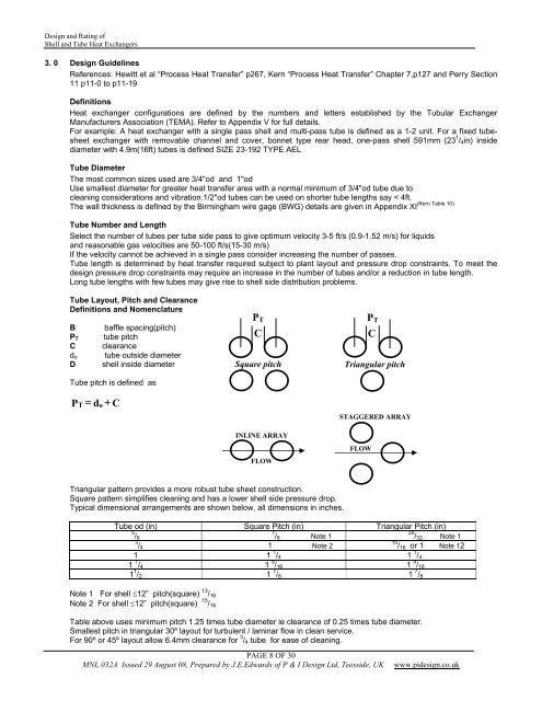
Tube Layout, Pitch and Clearance<br />
Definitions and Nomenclature<br />
B<br />
P T<br />
C<br />
d o<br />
D<br />
baffle spacing(pitch)<br />
tube pitch<br />
clearance<br />
tube outside diameter<br />
<strong>shell</strong> inside diameter<br />
Tube pitch is defined as<br />
PT = d + C<br />
o<br />
P T<br />
C<br />
Square pitch<br />
INLINE ARRAY<br />
FLOW<br />
P T<br />
C<br />
Triangular pitch<br />
STAGGERED ARRAY<br />
FLOW<br />
Triangular pattern provides a more robust tube sheet construction.<br />
Square pattern simplifies cleaning and has a lower <strong>shell</strong> side pressure drop.<br />
Typical dimensional arrangements are shown below, all dimensions in inches.<br />
Tube od (in) Square Pitch (in) Triangular Pitch (in)<br />
5 / 8 7 / 8 Note 1<br />
25 / 32 Note 1<br />
3 / 4 1 Note 2<br />
15 / 16 or 1 Note 12<br />
1 1 1 / 4 1 1 / 4<br />
1 1 / 4 1 9 / 16 1 9 / 16<br />
1 1 / 2 1 7 / 8 1 7 / 8<br />
Note 1 For <strong>shell</strong> ≤12” pitch(square) 13 / 16<br />
Note 2 For <strong>shell</strong> ≤12” pitch(square) 15 / 16<br />
Table above uses minimum pitch 1.25 times tube diameter ie clearance of 0.25 times tube diameter.<br />
Smallest pitch in triangular 30º layout for turbulent / laminar flow in clean service.<br />
For 90º or 45º layout allow 6.4mm clearance for 3 / 4 tube for ease of cleaning.<br />
PAGE 8 OF 30<br />
MNL 032A Issued 29 August 08, Prepared by J.E.Edwards of P & I Design Ltd, Teesside, UK<br />
www.pidesign.co.uk