

Rockford Systems Die Safety Blocks Catalog
Catalog that features a complete line of die safety blocks and accessories for use whenever dies are being adjusted or repaired. These products can also satisfy lockout/tagout requirements for isolating mechanical energy. The aluminum die safety blocks featured in the catalog are offered in several shapes and sizes. Products to choose from include: X-shaped, U-shaped, and Octagonal Safety blocks Adjustable Screw Devices for Use With Octagonal Safety Blocks Wedges Safety Block Holders Electrical Interlock Systems Adjustable Safety Blocks
Catalog that features a complete line of die safety blocks and accessories for use whenever dies are being adjusted or repaired. These products can also satisfy lockout/tagout requirements for isolating mechanical energy. The aluminum die safety blocks featured in the catalog are offered in several shapes and sizes. Products to choose from include:
X-shaped, U-shaped, and Octagonal Safety blocks
Adjustable Screw Devices for Use With Octagonal Safety Blocks
Wedges
Safety Block Holders
Electrical Interlock Systems
Adjustable Safety Blocks

You also want an ePaper? Increase the reach of your titles
YUMPU automatically turns print PDFs into web optimized ePapers that Google loves.
INTRODUCTION<br />
According to OSHA 29 CFR 1910.217, “The employer shall provide<br />
and enforce the use of safety blocks for use whenever dies are<br />
being adjusted or repaired in the press.” They are not required<br />
during die setting unless die blocks are included in your die setting<br />
procedure. They also satisfy the lockout/tagout requirements for<br />
isolating mechanical energy.<br />
<strong>Die</strong> safety blocks are placed between the die punch and holder with the<br />
machine stroke up. They are rated to support a static load. The static<br />
load represents the combined weight of the press ram, ram components<br />
(ram-adjust assembly and connection rod[s] or pitman arm[s]), and the<br />
upper die.<br />
In some applications, as many as four safety blocks may be required.<br />
This is determined by the size of the press bed and the weight the<br />
blocks must support. On larger presses, the total slide weight must then<br />
be distributed among the quantity of safety blocks required.<br />
The ram is usually adjustable; therefore, wedges or the adjustable<br />
screw device is offered to provide a proper fit. If the die takes up most<br />
of the space on the die set, it may be difficult to find a place to insert<br />
the block. To avoid accidentally stroking the press or leaving the safety<br />
block in the die after use, an electrical power cut-off interlock system<br />
should be used.<br />
Note: Electrical interlocking of die safety blocks to the machine’s motor<br />
and control circuits is required by ANSI B11.19.<br />
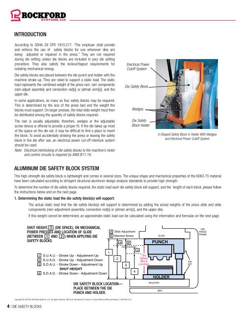
Electrical Power<br />
Cutoff System<br />
<strong>Die</strong> <strong>Safety</strong> Block<br />
Wedges<br />
<strong>Die</strong> <strong>Safety</strong><br />
Block Holder<br />
U-Shaped <strong>Safety</strong> Block in Holder With Wedges<br />
and Electrical Power Cutoff System<br />
ALUMINUM DIE SAFETY BLOCK SYSTEM<br />
This high-strength die safety block is lightweight and comes in several sizes. The unique shape and mechanical properties of the 6063-T5 material<br />
have been calculated according to stringent structural aluminum design analysis standards to provide high strength.<br />
To determine the number of die safety blocks required, the static load each die safety block will support, and the length of each block, please follow<br />
the instructions below and on the next page.<br />
1. Determining the static load the die safety block(s) will support:<br />
The actual static load that the die safety block(s) will support is determined by adding the actual weights of the press slide and slide<br />
components (ram-adjustment assembly, connection rod[s] or pitman arm[s], and the upper die).<br />
If this weight cannot be determined, an approximate static load can be calculated using the information and formulas on the next page.<br />
SHUT HEIGHT, 3 (DIE SPACE), ON MECHANICAL<br />
POWER PRESSES AND LOCATION OF SLIDE<br />
(BETWEEN 1 AND 2 ) WHEN APPLYING DIE<br />
SAFETY BLOCKS<br />
A Slide Adjustment<br />
B Machine Stroke<br />
A B<br />
SLIDE<br />
PUNCH<br />
OBI<br />
PRESS<br />
FRAME<br />
1 S.U.A.U. - Stroke Up - Adjustment Up<br />
2 S.U.A.D. - Stroke Up - Adjustment Down<br />
3 S.D.A.U. - Stroke Down - Adjustment Up<br />
SHUT HEIGHT<br />
4 S.D.A.D. - Stroke Down - Adjustment Down<br />
1<br />
2<br />
3<br />
4<br />
A<br />
<strong>Die</strong><br />
<strong>Safety</strong><br />
Block<br />
Location<br />
HOLDER<br />
DIE<br />
SET<br />
DIE SAFETY BLOCK LOCATION—<br />
PLACE BETWEEN THE DIE<br />
PUNCH AND HOLDER.<br />
BOLSTER<br />
BED<br />
Copyright © 2019 by <strong>Rockford</strong> <strong>Systems</strong>, LLC. All rights reserved. Not to be reproduced in whole or in part without written permission. LITHO IN U.S.A.<br />
4 | DIE SAEETY BLOCKS


