Programmer V5 EN
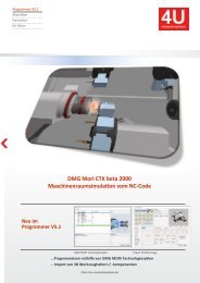
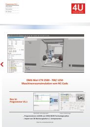
This is a multi-channel programming system for turning / milling machines with 3D machine room simulation. ● You create NC programs on the basis of an NC editor with machine macros and an integrated 2.5D CAD / CAM system. ● Templates are stored for different types of processing (bar / chuck ...). ● Program structures are generated automatically. ● The 3D machine space simulation shows the real machining process simultaneously. ● The actual implementation of the NC program is simulated. ● In the event of a collision, the relevant machine components and the associated NC blocks are displayed. What are the extensions of the V5.1 programmer? ● Project history and additional windows for further machine conditions ● Main and subprogram names are displayed in the simulation ● 3D blank (prismatic, rotationally symmetrical) is to be read in the STL format into the simulation ● The current workpiece is to be generated from the simulation as a 3D blank in the STL format ● Gaps can be measured in three dimensions ● NC block run times can be displayed as an EXCEL table
This is a multi-channel programming system for turning / milling machines with 3D machine room simulation.
● You create NC programs on the basis of an NC editor with machine macros and an integrated 2.5D CAD / CAM system.
● Templates are stored for different types of processing (bar / chuck ...).
● Program structures are generated automatically.
● The 3D machine space simulation shows the real machining process simultaneously.
● The actual implementation of the NC program is simulated.
● In the event of a collision, the relevant machine components and the associated NC blocks are displayed.
What are the extensions of the V5.1 programmer?
● Project history and additional windows for further machine conditions
● Main and subprogram names are displayed in the simulation
● 3D blank (prismatic, rotationally symmetrical) is to be read in the STL format into the simulation
● The current workpiece is to be generated from the simulation as a 3D blank in the STL format
● Gaps can be measured in three dimensions
● NC block run times can be displayed as an EXCEL table

You also want an ePaper? Increase the reach of your titles
YUMPU automatically turns print PDFs into web optimized ePapers that Google loves.
4 | CAD/CAM operations
Memo
4.4.1 Hiding elements
It may become necessary to hide contour elements for a specific operation. The "Linear"
function is provided for this purpose.
Select the "Linear" option.
Call the context menu using the right mouse button and e.g. select
the "Intersection" function.
Snap the intersection.
Select the end point as the next element.
The contour to be hidden is displayed in yellow.
After the selection of the end point, the linear element just as the contour are displayed
in magenta.
Referring to the roughing cycle described above, the undercut is now hidden for the
roughing operation, i.e. undercuts are not realized.
Using "All Fade In, any hidden elements can be shown again. When
selecting a subsequent finishing cycle,
the elements that were hidden in the roughing cycle will be shown
again automatically.
50
A-D821UK-1_200420