FIRST STEPS TOWARD SPACE - Smithsonian Institution Libraries
FIRST STEPS TOWARD SPACE - Smithsonian Institution Libraries
FIRST STEPS TOWARD SPACE - Smithsonian Institution Libraries

Create successful ePaper yourself
Turn your PDF publications into a flip-book with our unique Google optimized e-Paper software.
252 SMITHSONIAN ANNALS OF FLIGHT<br />
FIGURE 4.—Rocket fighter plane BI-1.<br />
the horizon) and after the engine stopped, to pass<br />
on to a gliding flight. For this purpose the rocket<br />
was provided with an automatic device, of a fairly<br />
primitive type, to deflect the elevators as predetermined<br />
by a prescribed time program. The first<br />
flights, however, performed in May 1934, showed<br />
that the 06/1 rocket motion was unstable. The<br />
rockets caused it to do loops, barrel-rolls, and other<br />
aerobatic figures but the design trajectory could not<br />
be obtained.<br />
Therefore, the next 06/III winged rocket (known<br />
later as a 216 rocket) was provided with ailerons in<br />
addition to elevators. For this purpose a two-axis<br />
gyroscopic autopilot was specially designed at RNII<br />
under the guidance of S. A. Pivovarov.<br />
The methods of trajectory calculation in 1934-35<br />
could be understood by referring to a system of<br />
equations (Figure 5) which were to be solved mathematically.<br />
Later, in 1936-38, the methods of calculating<br />
dynamic flight were considerably improved<br />
by engineer B. V. Raushenbakh; the rocket motion<br />
relative to the center of gravity acted upon by the<br />
autopilot was given special attention; and dynamic<br />
stability of the rocket was also considered.<br />
Characteristics of the 216 rocket were: Takeoff<br />
weight, 80 kg; maximum thrust of the 02 alcoholoxygen<br />
engine (OR-2 modified), 100 kg; propellant<br />
weight, 12 kg; wing area, 1.5 m 2 ; takeoff speed, 36<br />
m/sec; and maximum flight speed, 180 m/sec.<br />
Figure 6a shows a full-size 216 rocket under windtunnel<br />
tests. Figure 6b shows the main power plant<br />
elements mounted on the rocket thrust frame, also<br />
the wing-mounted oxygen tanks, a cylindrical alcohol<br />
tank, an 02 engine, and tanks of air to force the<br />
propellants out of the tanks and to drive the autopilot<br />
servo units. Figure 6c shows the GPS-2 gyroscopic<br />
two-axis autopilot.<br />
(z.^-PCo^-^-Gointff<br />
$-v&=P-6in«+R-60>!>fr<br />
I<br />
1 M<br />
a<br />
FIGURE 5.—Equations used for flight trajectory calculations.<br />
The 216 rocket was fired from a special catapult<br />
(Figure 6d) which was, essentially, a launching trolley,<br />
complete with one or three solid-propellant<br />
rockets, that slid on guide rails over a distance of<br />
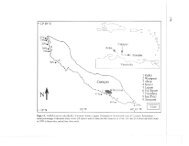
60 m. Figure 7 compares the design and experimental<br />
results for two launchings of reduced-size<br />
mockups of the 216 rocket.<br />
During the test flights, motion pictures of the<br />
takeoff were taken to determine the speed at which<br />
the rocket left the trolley. Special recording devices<br />
were employed to register the movement of the<br />
elevator and ailerons. Some of the rockets were<br />
provided with sodium flares to indicate flight<br />
trajectories.<br />
Four 216 winged rockets were tested between<br />
9 May and 4 November 1936, but only two firings<br />
went relatively successfully off the trolley. One of<br />
the rockets began to make a dead loop because of