

Rosemount 702 Wireless Discrete Transmitter - Emerson Process ...
Rosemount 702 Wireless Discrete Transmitter - Emerson Process ...
Rosemount 702 Wireless Discrete Transmitter - Emerson Process ...

You also want an ePaper? Increase the reach of your titles
YUMPU automatically turns print PDFs into web optimized ePapers that Google loves.
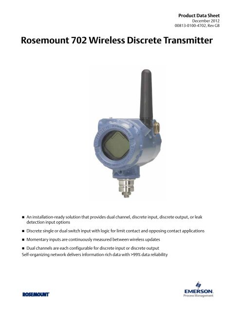
Product Data Sheet<br />
December 2012<br />
00813-0100-4<strong>702</strong>, Rev GB<br />
<strong>Rosemount</strong> <strong>702</strong> <strong>Wireless</strong> <strong>Discrete</strong> <strong>Transmitter</strong><br />
� An installation-ready solution that provides dual channel, discrete input, discrete output, or leak<br />
detection input options<br />
� <strong>Discrete</strong> single or dual switch input with logic for limit contact and opposing contact applications<br />
� Momentary inputs are continuously measured between wireless updates<br />
� Dual channels are each configurable for discrete input or discrete output<br />
Self-organizing network delivers information rich data with >99% data reliability
<strong>Rosemount</strong> <strong>702</strong> <strong>Wireless</strong> <strong>Discrete</strong> <strong>Transmitter</strong> December 2012<br />
<strong>Emerson</strong>’s Smart <strong>Wireless</strong> Solution<br />
Contents<br />
<strong>Emerson</strong>’s Smart <strong>Wireless</strong> Solution . . . . . . . . .page 2<br />
Ordering Information . . . . . . . . . . . . . . . . . . . . .page 3<br />
Specifications . . . . . . . . . . . . . . . . . . . . . . . . . . . .page 5<br />
2<br />
IEC 62591 (<strong>Wireless</strong>HART )... The Industry<br />
Standard<br />
Self-Organizing, Adaptive Mesh Routing<br />
� No wireless expertise required, network automatically<br />
finds the best communication paths<br />
� The self-organizing, self-healing network manages<br />
multiple communication paths for any given device. If an<br />
obstruction is introduced into the network, data will<br />
continue to flow because the device already has other<br />
established paths. The network will then lay in more<br />
communication paths as needed for that device.<br />
<strong>Emerson</strong>’s Smart <strong>Wireless</strong><br />
Reliable <strong>Wireless</strong> Architecture<br />
� Standard IEEE 802.15.4 radios<br />
� 2.4 GHz ISM band sliced into 15 radio-channels<br />
� Time Synchronized Channel Hopping to avoid interference<br />
from other radios, WiFi, and EMC sources and increase<br />
reliability<br />
� Direct sequence spread spectrum (DSSS) technology<br />
delivers high reliability in challenging radio environment<br />
SmartPower Solutions<br />
� Optimized <strong>Emerson</strong> instrumentation, both hardware and<br />
software, to extend power module life<br />
� Intrinsically safe power module allows field replacements<br />
without removing the transmitter from the process,<br />
keeping personnel safe, and reducing maintenance costs.<br />
Product Certifications . . . . . . . . . . . . . . . . . . . .page 14<br />
Dimensional Drawings . . . . . . . . . . . . . . . . . . . .page 18<br />
www.rosemount.com
December 2012<br />
Ordering Information<br />
Table 1. <strong>Rosemount</strong> <strong>702</strong> <strong>Wireless</strong> <strong>Discrete</strong> <strong>Transmitter</strong> Ordering Information<br />
www.rosemount.com<br />
<strong>Rosemount</strong> <strong>702</strong> <strong>Wireless</strong> <strong>Discrete</strong> <strong>Transmitter</strong><br />
★ The Standard offering represents the most common options. The starred options (★) should be selected for best delivery.<br />
__The Expanded offering is subject to additional delivery lead time.<br />
Product Description<br />
Standard Standard<br />
<strong>702</strong> <strong>Discrete</strong><strong>Transmitter</strong> ★<br />
<strong>Transmitter</strong> Type<br />
Standard Standard<br />
D <strong>Wireless</strong> Field Mount ★<br />
Output<br />
Standard Standard<br />
X <strong>Wireless</strong> ★<br />
Measurement<br />
Standard Standard<br />
22 Dual <strong>Discrete</strong> Inputs (Dry Contact) ★<br />
32 <strong>Discrete</strong> Dual Input (Dry Contact), Detects Momentary Inputs and Counts ★<br />
42 <strong>Discrete</strong> Dual Input or Output, Configurable ★<br />
61 (1)<br />
Liquid Hydrocarbon Detection (For use with TraceTek Fast Fuel Sensor or TraceTek sensing cable) ★<br />
Housing<br />
Standard Standard<br />
D Dual Compartment Housing - Aluminum ★<br />
E Dual Compartment Housing - SST ★<br />
Conduit Threads<br />
Standard Standard<br />
1 1 /2 - 14 NPT ★<br />
Certifications Measurement Option Codes<br />
Standard Standard<br />
I5<br />
FM Intrinsically Safe, Non-Incendive, and Dust<br />
Ignition-Proof<br />
22, 32, 61 ★<br />
I6 CSA Intrinsically Safe 22, 32, 61 ★<br />
I1 ATEX Intrinsic Safety 22, 32, 61 ★<br />
IU ATEX Intrinsic Safety for Zone 2 32, 42 ★<br />
I7 IECEx Intrinsic Safety 22, 32, 61 ★<br />
IY IECEx Intrinsic Safety for Zone 2 32, 42 ★<br />
I4 TIIS Intrinsic Safety 22 ★<br />
I3 China Intrinsic Safety 22 ★<br />
N5 FM Division 2, Non-Incendive 32, 42 ★<br />
N6 CSA Division2, Non-Incendive 32, 42 ★<br />
NA No Approval 22, 32, 42, 61 ★<br />
3
<strong>Rosemount</strong> <strong>702</strong> <strong>Wireless</strong> <strong>Discrete</strong> <strong>Transmitter</strong> December 2012<br />
Table 1. <strong>Rosemount</strong> <strong>702</strong> <strong>Wireless</strong> <strong>Discrete</strong> <strong>Transmitter</strong> Ordering Information<br />
★ The Standard offering represents the most common options. The starred options (★) should be selected for best delivery.<br />
__The Expanded offering is subject to additional delivery lead time.<br />
<strong>Wireless</strong> Options<br />
4<br />
<strong>Wireless</strong> Update Rate, Operating Frequency and Protocol<br />
Standard Standard<br />
WA3 User Configurable Update Rate, 2.4 GHz DSSS, IEC 62591 (<strong>Wireless</strong>HART) ★<br />
Omnidirectional <strong>Wireless</strong> Antenna and SmartPower Solutions<br />
Standard Standard<br />
WK1 External Antenna, Adapter for Black Power Module (I.S. Power Module Sold separately) (2)<br />
★<br />
WM1<br />
Extended Range, External Antenna, Adapter for Black Power Module (I.S. Power Module Sold<br />
separately) (2)<br />
★<br />
Expanded Expanded<br />
WN1 High-Gain, Remote Antenna, Adapter for Black Power Module (I.S. Power Module Sold separately)<br />
(2) (3)<br />
Other Options (Include with selected model number)<br />
Display<br />
Standard Standard<br />
M5 (1)<br />
LCD Display ★<br />
Mounting Bracket<br />
Standard Standard<br />
B4 Universal L mounting bracket for 2-inch pipe mounting - SST bracket and bolts ★<br />
Configuration<br />
Standard Standard<br />
C1 Factory Configure Date, Descriptor, Message Fields, and <strong>Wireless</strong> Parameters ★<br />
Cable Gland<br />
Standard Standard<br />
G2 Cable gland (7.5 mm - 11.9 mm) ★<br />
G4 (4) Thin Wire Cable Gland (3 mm - 8 mm) ★<br />
Switches and Kits<br />
Standard Standard<br />
SS01 Universal Safety Shower/Eyewash Kit with UL Switches ★<br />
SS02 Universal Safety Shower/Eyewash Kit for Insulated pipe with UL Switches ★<br />
SS03 Universal Safety Shower/Eyewash Kit with CSA Switches ★<br />
SS04 Universal Safety Shower/Eyewash Kit for Insulated Pipe with CSA Switches ★<br />
Typical Model Number: <strong>702</strong> D X 22 D 1 NA WA3 WK1 M5<br />
(1) LCD Display not available for option code 61.<br />
(2) Black Power Module must be shipped separately, order Model 701PBKKF or Part # 00753-9220-0001.<br />
(3) Limited availability, consult factory for details.<br />
(4) Thin wire cable gland is preferred for measurement option 61.<br />
www.rosemount.com
December 2012<br />
Specifications<br />
Functional Specifications<br />
<strong>Discrete</strong> Input<br />
Single or dual SPST dry contacts, single SPDT dry contacts or<br />
leak detection. To maintain I.S. ratings, contacts must be limited<br />
to simple switches or leak detection only.<br />
Switching Threshold, measurement option code 22:<br />
Open > 1000 Ohm<br />
Closed < 100 Ohm<br />
Switching Threshold, measurement option code 32<br />
and 42<br />
Open > 100 K Ohm<br />
Closed < 5 K Ohm<br />
Momentary <strong>Discrete</strong> Input, measurement option code<br />
32 and 42<br />
Detects momentary discrete inputs of 10 millisecond or more<br />
duration. At each wireless update, device reports current<br />
discrete state and accumulating count of close-open cycles.<br />
Accumulating count registers from 0 to 999,999, then re-sets to<br />
0.<br />
<strong>Discrete</strong> Output, measurement option Code 42<br />
Maximum Rating: 26 Vdc, 100 mA<br />
On resistance: typical 1 Ohm<br />
<strong>Wireless</strong> Output<br />
IEC 62591 (<strong>Wireless</strong>HART) 2.4 GHz DSSS.<br />
Radio Frequency Power Output from Antenna<br />
External (WK option) antenna: Maximum of 10 mW (10 dBm)<br />
EIRP<br />
Extended Range, External (WM option) antenna: Maximum of 18<br />
mW (12.5 dBm) EIRP<br />
High Gain, Remote (WN option) antenna: Maximum of 40 mW<br />
(16 dBm) EIRP<br />
Local Display (1)<br />
The optional integral LCD can display discrete state and<br />
diagnostic information. Display updates at each wireless<br />
update.<br />
(1) The option for a local display is not available with option 61, Liquid<br />
Hydrocarbon Leak Detection.<br />
Humidity Limits<br />
0–100% relative humidity<br />
<strong>Wireless</strong> Update Rate, measurement option code 32,<br />
42<br />
User selectable, 1 sec. to 60 min.<br />
www.rosemount.com<br />
<strong>Rosemount</strong> <strong>702</strong> <strong>Wireless</strong> <strong>Discrete</strong> <strong>Transmitter</strong><br />
<strong>Wireless</strong> Update Rate, measurement option code 22,<br />
61<br />
User selectable, 4 sec. to 60 min.<br />
Physical Specifications<br />
Electrical Connections<br />
<strong>Wireless</strong> Power Module<br />
Replaceable, Intrinsically Safe Lithium-Thionyl Chloride<br />
power module with PBT polymer enclosure. Ten year life at<br />
one minute update rate. (1)<br />
(1) Reference conditions are 70° F (21° C), and routing data for three<br />
additional network devices.<br />
NOTE: Continuous exposure to ambient temperature limits (-40 °F or<br />
185 °F) (-40 °C or 85 °C) may reduce specified power module life by<br />
less than 20 percent.<br />
Switch Terminals<br />
Screw terminals permanently fixed to terminal block<br />
Field Communicator Connections<br />
Communication Terminals<br />
Clips permanently fixed to terminal block<br />
Materials of Construction<br />
Enclosure<br />
Housing - Low-copper aluminum, or stainless steel<br />
Paint - Polyurethane<br />
Cover O-ring - Buna-N<br />
Terminal Block and Power Module Pack<br />
PBT<br />
Antenna<br />
PBT/PC integrated omnidirectional antenna<br />
Conduit Entries<br />
1 /2 - 14 NPT<br />
Weight<br />
Low - Copper Aluminum:<br />
<strong>702</strong> without LCD - 4.6 lbs. (2.0 kg)<br />
<strong>702</strong> with M5 LCD - 4.7 lbs (2.1 kg)<br />
Stainless Steel:<br />
<strong>702</strong> without LCD - 8.0 lbs. (3.6 kg)<br />
<strong>702</strong> with M5 LCD - 8.1 lbs (3.7 kg<br />
Enclosure Ratings (<strong>702</strong>)<br />
NEMA 4X, and IP66/67.<br />
Mounting<br />
<strong>Transmitter</strong>s may be attached directly to switch, brackets also<br />
permit remote mounting. See “Dimensional Drawings” on<br />
page 18.<br />
5
<strong>Rosemount</strong> <strong>702</strong> <strong>Wireless</strong> <strong>Discrete</strong> <strong>Transmitter</strong> December 2012<br />
Performance Specifications<br />
ElectroMagnetic Compatibility (EMC)<br />
All Models:<br />
Meets all relevant requirements of EN 61326-2-3:2006<br />
Vibration Effect<br />
<strong>Wireless</strong> output unaffected when tested per the requirements of<br />
IEC60770-1 field or pipeline with high vibration level (10-60 Hz<br />
0.21mm displacement peak amplitude / 60-2000 Hz 3g).<br />
<strong>Wireless</strong> output unaffected when tested per the requirements of<br />
IEC60770-1 field with general application or pipeline with low<br />
vibration level (10-60 Hz 0.15mm displacement peak amplitude<br />
/ 60-500 Hz 2g).<br />
Temperature Limits<br />
Description Operating Limit Storage Limit<br />
Without LCD –40 to 185 °F –40 to 185 °F<br />
Display<br />
–40 to 85 °C –40 to 85 °C<br />
Dry Contact Switch Inputs, Measurement option<br />
code 22, 32, and 42<br />
Terminal Block Connections<br />
The <strong>Rosemount</strong> <strong>702</strong> <strong>Transmitter</strong> has a pair of screw terminals for<br />
each of two channels, and a pair of communication terminals.<br />
These terminals are labeled as follows:<br />
CH1+: Channel One Positive<br />
CMN: Common<br />
CH2+: Channel Two Positive<br />
CMN: Common<br />
COMM: Communication Terminals<br />
6<br />
With LCD Display<br />
–4 to 175 °F<br />
–20 to 80 °C<br />
–40 to 185 °F<br />
–40 to 85 °C<br />
Figure 1. <strong>Rosemount</strong> <strong>702</strong> Terminal Block Connections<br />
<strong>Wireless</strong> Output Specifications<br />
Dry Contact Switch Inputs, Measurement option code 22,<br />
32, and 42<br />
Single Input or Dual Input Independent<br />
The <strong>Rosemount</strong> <strong>702</strong> <strong>Discrete</strong> <strong>Transmitter</strong> will accept the input<br />
from one or two single pole single throw switches on inputs CH1<br />
and CH2. The wireless output of the transmitter will be both a<br />
primary variable (PV) and a secondary variable (SV). The PV is<br />
determined by the CH1 input. The SV is determined by the CH2<br />
input. A closed switch drives a TRUE output. An Open switch<br />
drives a FALSE output.<br />
www.rosemount.com
December 2012<br />
Note<br />
Any dry contact input can be inverted by the device, so as<br />
to give the opposite effect. This is useful, for instance, if a<br />
normally open switch is used to replace a normally closed<br />
switch.<br />
Figure 2. Single, Dual Input<br />
Single or Dual Input, No Logic<br />
Switch<br />
Input<br />
<strong>Wireless</strong><br />
Output<br />
Dual Input, Limit Contact Logic<br />
www.rosemount.com<br />
Switch Input <strong>Wireless</strong><br />
Output<br />
CH1 PV CH2 SV<br />
Closed TRUE (1.0) Closed TRUE (1.0)<br />
Open FALSE (0.0) Open FALSE (0.0)<br />
<strong>Rosemount</strong> <strong>702</strong> <strong>Wireless</strong> <strong>Discrete</strong> <strong>Transmitter</strong><br />
When configured for Limit Contact Logic, the <strong>Rosemount</strong> <strong>702</strong><br />
<strong>Discrete</strong> <strong>Transmitter</strong> will accept the input from two single pole<br />
single throw switches on inputs CH1 and CH2, and will use limit<br />
contact logic for the determination of the wireless outputs.<br />
Figure 3. Dual Input, Limit Contacts<br />
Dual Input, Limit Contact Logic<br />
Switch Inputs <strong>Wireless</strong> Outputs<br />
CH1 CH2 PV SV<br />
Open Open TRAVEL (0.5) TRAVEL (0.5)<br />
Open Closed FALSE (0.0) FALSE (0.0)<br />
Closed Open TRUE (1.0) TRUE (1.0)<br />
Closed Closed FAULT(NaN) FAULT(NaN)<br />
Dual Input, Opposing Contact Logic<br />
When configured for Opposing Contact Logic, the <strong>Rosemount</strong><br />
<strong>702</strong> <strong>Discrete</strong> <strong>Transmitter</strong> will accept the input from a double<br />
pole single throw switch on inputs CH1 and CH2, and will use<br />
opposing contact logic for the determination of the wireless<br />
outputs.<br />
Figure 4. Dual Input, Opposing Contact<br />
7
<strong>Rosemount</strong> <strong>702</strong> <strong>Wireless</strong> <strong>Discrete</strong> <strong>Transmitter</strong> December 2012<br />
Momentary <strong>Discrete</strong> Inputs, measurement option code 32<br />
and 42<br />
The <strong>Rosemount</strong> <strong>702</strong> wireless discrete transmitter is capable of<br />
detecting momentary discrete inputs of 10 millisecond or more<br />
in duration, regardless of the wireless update rate. At each<br />
wireless update, the device reports current discrete state along<br />
with an accumulating count of close-open cycles for each input<br />
channel.<br />
Figure 5. Momentary Inputs and Accumulating Count<br />
Figure 6. Reporting of Current <strong>Discrete</strong> State and<br />
Count in AMS Device Manager<br />
8<br />
Dual Input, Opposing Contact Logic<br />
Switch Inputs <strong>Wireless</strong> Outputs<br />
CH1 CH2 PV SV<br />
Open Open FAULT(NaN) FAULT(NaN)<br />
Open Closed FALSE (0.0) FALSE (0.0)<br />
Closed Open TRUE (1.0) TRUE (1.0)<br />
Closed Closed FAULT(NaN) FAULT(NaN)<br />
Variable Reporting and Mapping<br />
The <strong>Rosemount</strong> <strong>702</strong> <strong>Transmitter</strong> has two choices for variable<br />
reporting: Classic – <strong>Discrete</strong> State Only, or Enhanced – <strong>Discrete</strong><br />
State and Count. In the Classic variable reporting mode, the<br />
<strong>Rosemount</strong> <strong>702</strong> transmitter will report variables exactly like the<br />
previous version of the device (measurement option code 22). In<br />
the Enhanced variable reporting mode, the <strong>Rosemount</strong> <strong>702</strong><br />
transmitter will provide both current state of the discrete<br />
channels, and a count of the discrete state change cycles.<br />
Following is a table that shows the variable mapping for both<br />
cases. Variable Reporting can be set in AMS Device Manager by<br />
going to Configure > Manual Setup > HART.<br />
Table 2. Variable Mapping<br />
Variable<br />
Variable Mapping<br />
Reporting<br />
Classic –<br />
<strong>Discrete</strong> State<br />
Only<br />
Enhanced –<br />
<strong>Discrete</strong> State<br />
with Count<br />
PV SV TV QV<br />
CH1<br />
State<br />
CH1<br />
State<br />
CH2<br />
State<br />
CH2<br />
State<br />
Electronics<br />
Temperature<br />
CH1 Count<br />
Supply<br />
Voltage<br />
CH2<br />
Count<br />
<strong>Discrete</strong> Output Circuits, Measurement Option<br />
Code 42<br />
The <strong>Rosemount</strong> <strong>702</strong> wireless discrete transmitter has two<br />
channels that can each be configured for discrete input or<br />
output. Inputs must be dry contact switch inputs and these were<br />
described in a preceding section of this document. Outputs are<br />
a simple switch closure to activate an output circuit. The<br />
<strong>Rosemount</strong> <strong>702</strong> output does not provide any voltage or current,<br />
the output circuit must have power of its own. The <strong>Rosemount</strong><br />
<strong>702</strong> output has maximum switch capacity per channel of 26<br />
volts DC and 100 milliamps. A typical power supply for powering<br />
an output circuit can be 24 volts or lower.<br />
Note<br />
It is very important that the polarity of the output circuit<br />
is as shown in the wiring diagrams, with the positive (+)<br />
side of the circuit wired to the CH1+ or the CH2 +<br />
terminal, and the negative (-) side of the circuit wired to<br />
the CMN terminal. If the output circuit is wired<br />
backwards, it will remain active (switch closed) regardless<br />
of the state of the output channel.<br />
www.rosemount.com
December 2012<br />
<strong>Discrete</strong> Output Switch Functionality<br />
The discrete output of the <strong>Rosemount</strong> <strong>702</strong> transmitter is driven<br />
by the host control system, through the Smart <strong>Wireless</strong><br />
Gateway, and out to the <strong>Rosemount</strong> <strong>702</strong> <strong>Transmitter</strong>. The time<br />
required for this wireless communication from the Gateway to<br />
the <strong>Rosemount</strong> <strong>702</strong> transmitter is dependent on many factors,<br />
including the size and topology of the network and the total<br />
amount of downstream traffic on the wireless network. For a<br />
network that is constructed to our best practices, typical delays<br />
in communication of a discrete output from the Gateway to the<br />
<strong>Rosemount</strong> <strong>702</strong> transmitter are 15 seconds or less. Remember<br />
that this delay is only part of the latency that well be observed in<br />
a control loop.<br />
Note<br />
The output switch functionality of the <strong>Rosemount</strong> <strong>702</strong><br />
transmitter requires that the network is managed by a<br />
version 3 Smart <strong>Wireless</strong> Gateway with v3.9.7 firmware,<br />
or a version 4 Gateway with v4.3 or higher firmware<br />
installed.<br />
Figure 7. Output Circuit Wiring<br />
Figure 8. Possible Configurations for Both Channel 1<br />
and Channel 2<br />
www.rosemount.com<br />
<strong>Rosemount</strong> <strong>702</strong> <strong>Wireless</strong> <strong>Discrete</strong> <strong>Transmitter</strong><br />
Special Considerations for dual output circuits<br />
If both channels are connected to output circuits, it is very<br />
important that the CMN terminal of each circuit be at the same<br />
voltage. Employing a common ground for both output circuits is<br />
one way to ensure that both circuits have CMN terminals at the<br />
same voltage.<br />
Figure 9. Dual Output Circuits with a Common Ground<br />
If two output circuits are connected to a single <strong>Rosemount</strong> <strong>702</strong><br />
transmitter with a single power supply, both CH + and CMN<br />
terminals must be connected to each output circuit. The<br />
negative power supply wires must be at the same voltage and<br />
connected to both CMN terminals.<br />
Figure 10. Dual Output Circuits with One Power<br />
Supply<br />
9
<strong>Rosemount</strong> <strong>702</strong> <strong>Wireless</strong> <strong>Discrete</strong> <strong>Transmitter</strong> December 2012<br />
Switching Greater Currents or Voltages<br />
It is important to note that the maximum output switching<br />
capacity is 26 volts DC and 100 milliamps. If a greater voltage or<br />
current is to be switched, an interposing relay circuit can be<br />
used. Figure 11 shows an example of a circuit to switch higher<br />
currents or voltages.<br />
Figure 11. Wiring an Interposing Relay to Switch<br />
Greater Currents or Voltages<br />
10<br />
Leak Sensors, Liquid Hydrocarbon Detection,<br />
measurement option code 61<br />
Terminal Block Connections<br />
The Liquid Hydrocarbon Detection configuration is intended for<br />
use with the Tyco® Trace Tek® Fast Fuel Sensor, or TraceTek<br />
sensing cable.<br />
Figure 12. Fuel Sensor Terminal Diagram<br />
Figure 13. Fuel Sensor Connection Diagram<br />
www.rosemount.com
December 2012<br />
The connections to the Fast Fuel Sensor TraceTek sensing cable<br />
are made by matching the appropriately colored wires to the<br />
matching colored termination lugs.<br />
� The <strong>Emerson</strong> Smart <strong>Wireless</strong> <strong>702</strong> <strong>Discrete</strong> <strong>Transmitter</strong> can<br />
support up to 3 Fast Fuel sensors. These Fast Fuel sensors are<br />
connected using TraceTek Modular Leader Cable<br />
(TT-MLC-MC-BLK), optional modular jumper cables<br />
(TT-MJC-xx-MC-BLK) and branching connectors<br />
(TT-ZBC-MC-BLK) as suggested in Figure 14.<br />
Figure 14. Fuel Sensor wiring<br />
TT-MLC-MC-BLK (Leader Cable)<br />
� The <strong>Emerson</strong> Smart <strong>Wireless</strong> <strong>702</strong> <strong>Discrete</strong> <strong>Transmitter</strong> can<br />
support up to 500 feet of TraceTek hydrocarbon or solvent<br />
sensor cable (TT5000 or TT5001 series). The total amount of<br />
sensor cable connected to a single <strong>702</strong> transmitter is not to<br />
exceed 500 ft. However leader cable, jumper cables (if used),<br />
and branch connectors are not included in the 500 foot (150<br />
m) limit. See Figure 15 for typical configurations.<br />
www.rosemount.com<br />
TT-FFS-100 or TT-FFS-250<br />
(Fast Fuel Sensor Probe)<br />
TT-MLC-MC-BLK (Leader Cable)<br />
TT-MJC-xx-MC-BLK (Optional Jumper Cable)<br />
TT-ZBC-xx-MC-BLK<br />
(Branch Connector)<br />
TT-FFS-100 or TT-FFS-250<br />
(Fast Fuel Sensor Probe)<br />
<strong>Rosemount</strong> <strong>702</strong> <strong>Wireless</strong> <strong>Discrete</strong> <strong>Transmitter</strong><br />
Figure 15. Fuel Sensor sensor cable wiring<br />
TT-MLC-MC-BLK (Leader Cable)<br />
TT5000/TT5000 Sensor Cable (up<br />
to 500 ft.)<br />
TT-MET-MC (End Termination)<br />
TT-MJC-xx-MC-BLK (Optional Jumper Cable)<br />
TT-ZBC-xx-MC-BLK<br />
(Branch Connector)<br />
TT-MET-MC<br />
(End Termination)<br />
TT-MET-MC<br />
(End Termination)<br />
Up to 500 ft. TT5000 or TT5001<br />
sensor cable<br />
(Total per <strong>702</strong>)<br />
11
<strong>Rosemount</strong> <strong>702</strong> <strong>Wireless</strong> <strong>Discrete</strong> <strong>Transmitter</strong> December 2012<br />
Safety Shower and Eye Wash Monitoring<br />
The <strong>Rosemount</strong> <strong>702</strong> transmitter can be used to monitor safety<br />
showers and eye wash stations by using switch kits provided by<br />
TopWorx, an <strong>Emerson</strong> company. These kits are ordered as a part<br />
of the <strong>Rosemount</strong> <strong>702</strong> model code and are available for both<br />
insulated and un-insulated pipes. These kits contain the<br />
switches, brackets and cables that are necessary to install the<br />
<strong>Rosemount</strong> <strong>702</strong> to monitor both the safety shower and the eye<br />
wash in a single station. Because each has two input channels,<br />
one <strong>Rosemount</strong> <strong>702</strong> transmitter can be used to monitor both a<br />
safety shower and an eye wash.<br />
Each Safety Shower Monitoring kit contains:<br />
� Two TopWorx Go Switch magnetic proximity switches<br />
� Two cables, one six foot and one 12 foot<br />
� Two black polymer cable glands<br />
� Mounting kit for safety shower and eye wash<br />
12<br />
Safety Shower monitoring<br />
When the shower valve is activated (valve open) by pulling<br />
down on the handle, the TopWorx switch is activated (closed<br />
switch) and the <strong>702</strong> transmitter senses that switch closure. This<br />
switch state is then transmitted by the <strong>702</strong> transmitter to the<br />
Gateway, which then sends that information to the control host<br />
or alert system. When the shower valve is closed, the switch<br />
remains in the activated state until it is reset by a technician. The<br />
switch can be re-set only by placing a ferrous metal object on<br />
the far side of the sensing area of the switch.<br />
Figure 16. TopWorx switch installed on a safety<br />
shower.<br />
Figure 17. Detail of the switch installation on a safety<br />
shower.<br />
www.rosemount.com
December 2012<br />
Figure 18. Safety shower valve in the activated<br />
position.<br />
Eye Wash Monitoring<br />
When the eye wash valve is activated (valve open) by pushing<br />
down on the hand paddle, the TopWorx switch is activated<br />
(closed switch) and the <strong>702</strong> transmitter senses that switch<br />
closure. This switch state is then transmitted by the <strong>702</strong><br />
transmitter to the Gateway, which then sends that information<br />
to the control host or alert system. When the eye wash valve is<br />
closed, the switch remains in the activated state until it is reset<br />
by a technician. The switch can be re-set only by placing a<br />
ferrous metal object on the far side of the sensing area of the<br />
switch.<br />
Figure 19. TopWorx switch installed on an eye wash<br />
station.<br />
www.rosemount.com<br />
<strong>Rosemount</strong> <strong>702</strong> <strong>Wireless</strong> <strong>Discrete</strong> <strong>Transmitter</strong><br />
Figure 20. Eye wash in activated position<br />
13
<strong>Rosemount</strong> <strong>702</strong> <strong>Wireless</strong> <strong>Discrete</strong> <strong>Transmitter</strong> December 2012<br />
Product Certifications<br />
Approved Manufacturing Locations<br />
14<br />
<strong>Rosemount</strong> Inc. – Chanhassen, Minnesota, USA<br />
<strong>Emerson</strong> <strong>Process</strong> Management GmbH & Co. - Karlstein,<br />
Germany<br />
<strong>Emerson</strong> <strong>Process</strong> Management Asia Pacific Private Limited<br />
- Singapore<br />
European Union Directive Information<br />
The most recent revision of the EC Declaration of<br />
Conformity can be found at www.rosemount.com under<br />
Documentation or in the <strong>Rosemount</strong> <strong>702</strong> <strong>Wireless</strong><br />
<strong>Discrete</strong> <strong>Transmitter</strong> Quick Start Guide (doc. number<br />
00825-0200-4<strong>702</strong>).<br />
Telecommunication Compliance<br />
All wireless devices require certification to ensure that they<br />
adhere to regulations regarding the use of the RF<br />
spectrum. Nearly every country requires this type of<br />
product certification. <strong>Emerson</strong> is working with<br />
governmental agencies around the world to supply fully<br />
compliant products and remove the risk of violating<br />
country directives or laws governing wireless device usage.<br />
FCC and IC<br />
This device complies with Part 15 of the FCC Rules.<br />
Operation is subject to the following conditions: This<br />
device may not cause harmful interference. This device<br />
must accept any interference received, including<br />
interference that may cause undesired operation.<br />
This device must be installed to ensure a minimum<br />
antenna separation distance of 20 cm from all persons.<br />
Ordinary Location Certification for FM Approvals<br />
As standard, the transmitter has been examined and<br />
tested to determine that the design meets basic electrical,<br />
mechanical, and fire protection requirements by FM<br />
Approvals, a nationally recognized testing laboratory<br />
(NRTL) as accredited by the Federal Occupational Safety<br />
and Health Administration (OSHA).<br />
Hazardous Locations Certificates<br />
North American certifications<br />
FM approvals<br />
I5 FM Approvals Intrinsically Safe, Non-Incendive and Dust<br />
Ignition-proof<br />
Certificate Number: 3031506<br />
Applicable Standards: Class 3600, 1998; Class 3610, 2010;<br />
Class 3611, 2004; Class 3810, 2005; ANSI/NEMA 250<br />
Marking: IS CL I,II,III, DIV 1, GP A, B, C, D, E, F, G.<br />
NI CL I, DIV 2, GP A, B, C, D.<br />
IS CL I, Zone 0, AEx ia llC<br />
T4 Ta =-50 to 70°C<br />
DIP CL II/III, DIV 1, GP E, F, G, AMB TEMP LIMITS -50<br />
TO 85°C<br />
WHEN INSTALLED PER ROSEMOUNT DWG<br />
00<strong>702</strong>-1000.<br />
FOR USE WITH EMERSON SMARTPOWER OPTION<br />
701PBKKF<br />
WARNING – POTENTIAL ELECTROSTATIC CHARGING<br />
HAZARD – SEE INSTRUCTIONS<br />
ENCLOSURE TYPE 4X<br />
IP66 / 67<br />
Special conditions of certification:<br />
1. The Model <strong>702</strong> transmitter housing contains aluminum and is<br />
considered a potential risk of ignition by impact or friction.<br />
Care must be taken into account during installation and use to<br />
prevent impact and friction.<br />
2. The surface resistivity of the polymeric antenna is greater<br />
than 1 G�. To avoid electrostatic charge build-up, it must not<br />
be rubbed or cleaned with solvents or a dry cloth.<br />
3. For use only with the Model 701P or <strong>Rosemount</strong><br />
753-9220-XXXX Smart Power Battery Module.<br />
N5 FM Approvals Non-Incendive and Dust Ignition-proof<br />
Certificate Number: 3031506<br />
Applicable Standards: Class 3600, 1998; Class 3611, 2004;<br />
Class 3810, 2005; ANSI/NEMA 250<br />
Marking: NI CL I, DIV 2, GP A, B, C, D.<br />
T4 Ta =-50 to 70°C<br />
DIP CL II/III, DIV 1, GP E, F, G, AMB TEMP LIMITS -50 TO<br />
85°C<br />
WHEN INSTALLED PER ROSEMOUNT DWG 00<strong>702</strong>-1000.<br />
FOR USE WITH EMERSON SMART POWEROPTION<br />
701PBKKF<br />
WARNING – POTENTIAL ELECTROSTATIC CHARGING<br />
HAZARD – SEE INSTRUCTIONS<br />
ENCLOSURE TYPE 4X<br />
IP66 / 67<br />
Special Conditions of Certification:<br />
1. For use only with the Model 701P or <strong>Rosemount</strong><br />
753-9220-XXXX Smart Power Battery Module.<br />
www.rosemount.com
December 2012<br />
CSA International<br />
I6 CSA Intrinsically Safe<br />
Certificate Number: 1143113<br />
Applicable Standards: CAN/CSA Std. 22.2 No. 0-10, CSA<br />
Std. 22.2 No. 142-M1987, CAN/CSA Std. 22.2 No. 157-92,<br />
CSA Std. 22.2 No. 60529:05<br />
Markings:Ex ia; INT. SAFE FOR USE IN CL I, DIV 1, GP A, B, C,<br />
D HAZ. LOC.<br />
TEMP CODE T3C<br />
ENCLOSURE TYPE 4X, IP66 / IP67<br />
FOR USE WITH EMERSON PROCESS MANAGEMENT<br />
SMARTPOWER OPTION 701PBKKF<br />
WHEN INSTALLED PER ROSEMOUNT DWG 00<strong>702</strong>-1020<br />
Switch Terminal Output<br />
Parameter Limits Option<br />
Code 32<br />
N6 CSA Class I Division 2<br />
Certificate Number: 1143113<br />
Applicable Standards: CAN/CSA Std. 22.2 No. 0-10, CSA<br />
Std. 22.2 No. 142-M1987, CSA Std. 22.2 No. 213-M1987,<br />
CSA Std. 22.2 No. 60529:05<br />
Markings:SUITABLE FOR USE IN CL I, DIV 2, GP A, B, C, D<br />
HAZ. LOC.<br />
TEMP CODE: T3C<br />
FOR USE WITH EMERSON SMART POWEROPTION<br />
701PBKKF<br />
ENCLOSURE TYPE 4X, IP66 / 67<br />
European certifications<br />
I1 ATEX Intrinsic Safety<br />
Certificate No.: Baseefa 07ATEX0239X<br />
Applicable Standards: IEC 60079-0: 2011, EN60079-11:<br />
2012<br />
Markings: II 1G Ex ia IIC T5 Ga (–60 °C ≤ Tamb ≤ +40 °C);<br />
Ex ia IIC T4 Ga (–60 °C ≤ Tamb ≤ +70 °C)<br />
1180<br />
IP66 / IP67<br />
FOR USE WITH ROSEMOUNT SMARTPOWER POWER<br />
MODULE PART NUMBER 753-9220-0001, or FOR USE<br />
WITH EMERSON PROCESS MANAGEMENT SMART POWER<br />
OPTION 701PBKKF<br />
www.rosemount.com<br />
Fuel Sensor Terminal<br />
Parameters Option<br />
Code 61<br />
Uo = 6.6 V Uo = 7.8 V<br />
Io = 13.37 mA Io = 92 mA<br />
Po = 21.77 mW Po = 180 mW<br />
Ca = 21.78 uF Ca = 9.2 uF<br />
La = 198 mH La = 5 mH<br />
Switch Terminal Output Parameter Limits Option<br />
Code 22<br />
Uo = 6.6 V<br />
Io = 26.2 mA<br />
Po = 42.6 mW<br />
Ca = 23.8 uF<br />
La = 50 mH<br />
<strong>Rosemount</strong> <strong>702</strong> <strong>Wireless</strong> <strong>Discrete</strong> <strong>Transmitter</strong><br />
WARNING – POTENTIAL ELECTROSTATIC CHARGING<br />
HAZARD – SEE INSTRUCTIONS<br />
SWITCH TERMINAL<br />
OUTPUT PARAMETER<br />
LIMITS Option Code 32<br />
FUEL SENSOR<br />
TERMINAL<br />
PARAMETERS Option<br />
Code 61<br />
Uo = 6.6 V Uo = 7.8 V<br />
Io = 13.4 mA Io = 92 mA<br />
Po = 21.8 mW Po = 180 mW<br />
Ci = 0.216 uF Ci = 10 nF<br />
CoIIC = 23.78 uF CoIIC = 9.2 uF<br />
CoIIB = 549.78 uF CoIIB = 129 uF<br />
CoIIA = 1000 uF CoIIA = 1000 uF<br />
Li=0 Li=0<br />
LoIIC = 200 mH LoIIC = 4.2 mH<br />
LoIIB = 800 mH LoIIB = 16.8 mH<br />
LoIIA = 1000 mH LoIIA = 33.6 mH<br />
SWITCH TERMINAL OUTPUT PARAMETER LIMITS<br />
Option Code 22<br />
Uo = 6.6 V<br />
Io = 26 mA<br />
Po = 42.6 mW<br />
Co = 11 uF<br />
Lo = 25 mH<br />
Special Conditions for Safe Use (X)<br />
1. The surface resistivity of the antenna is greater than 1G�. To<br />
avoid electrostatic change build-up, it must not be rubbed or<br />
cleaned with solvents or a dry cloth.<br />
NM ATEX Intrinsic Safety for Mining applications<br />
Certificate No.: Baseefa 07ATEX0239X<br />
Applicable Standards: IEC 60079-0: 2011, EN60079-11:<br />
2012<br />
Markings: I M1 Ex ia I Ma (-60 °C ≤ Ta ≤ +70 °C)<br />
1180<br />
IP66 / IP67<br />
FOR USE WITH EMERSON PROCESS MANAGEMENT SMART<br />
POWER OPTION 701PBKKF<br />
WARNING – POTENTIAL ELECTROSTATIC CHARGING<br />
HAZARD – SEE INSTRUCTIONS<br />
SWITCH TERMINAL OUTPUT PARAMETER<br />
LIMITS Option Code 32<br />
Uo = 6.6 V<br />
Io = 13.4 mA<br />
Po = 21.8 mW<br />
Ci = 0.216 uF<br />
CoIIC = 23.78 uF<br />
CoIIB = 549.78 uF<br />
CoIIA = 1000 uF<br />
Li=0<br />
LoIIC = 200 mH<br />
LoIIB = 800 mH<br />
LoIIA = 1000 mH<br />
15
<strong>Rosemount</strong> <strong>702</strong> <strong>Wireless</strong> <strong>Discrete</strong> <strong>Transmitter</strong> December 2012<br />
Special Conditions for Safe Use (X)<br />
1. The surface resistivity of the antenna is greater than 1G�. To<br />
avoid electrostatic change build-up, it must not be rubbed or<br />
cleaned with solvents or a dry cloth.<br />
IU ATEX Intrinsic Safety for Zone 2<br />
Certificate Number: Baseefa12ATEX0122X<br />
Applicable Standards: IEC 60079-0: 2011, EN60079-11:<br />
2012<br />
Markings: 3G Ex ic IIC T4 Gc (-60 °C ≤ Ta ≤ +70 °C)<br />
Ex ic IIC T5 Gc (-60 °C ≤ Ta ≤ +40 °C)<br />
IP66 / IP67<br />
FOR USE WITH EMERSON PROCESS MANAGEMENT SMART<br />
POWEROPTION 701PBKKF<br />
Specific Conditions of Use<br />
1. The surface resistivity of the antenna is greater than 1 G�. To<br />
avoid electrostatic charge build-up, it must not be rubbed or<br />
cleaned with solvents or a dry cloth.<br />
2. The Model 701PB Power Module may be replaced in a<br />
hazardous area. The Power Module has surface resistivity<br />
greater than 1 G� and must be properly installed in the<br />
wireless device enclosure. Care must be taken during<br />
transportation to and from the point of installation to prevent<br />
electrostatic charge build-up.<br />
16<br />
SWITCH<br />
TERMINAL<br />
OUTPUT<br />
PARAMETER<br />
LIMITS Option<br />
Code 32<br />
Switch Terminal Parameters<br />
Option Code 42<br />
Input Output<br />
U o = 6.6 V U o = 6.6 V U i = 26 V<br />
I o = 13.4 mA I o = 13.4 mA I i = 100 mA<br />
P o = 21.8 mW P o = 21.8 mW P i = 65 W<br />
C i = 0.216 uF Ci= 0.216 uF Ci= 0.216 uF<br />
Co IIC = 23.78 uF Co IIC = 23.78 uF Li=0<br />
Co IIB = 549.78 uF Co IIB = 549.78 uF<br />
Co IIA = 1000 uF Co IIA = 1000 uF<br />
Li=0 Li=0<br />
Lo IIC = 200 mH Lo IIC = 200 mH<br />
Lo IIB = 800 mH Lo IIB = 800 mH<br />
Lo IIA = 1000 mH Lo IIA = 1000 mH<br />
IECEx System Certifications<br />
I7 IECEx Intrinsic Safety<br />
Certificate No.: IECEx BAS 07.0082X<br />
Applicable Standards: IEC 60079-0: 2011, IEC 60079-11:<br />
2011<br />
Markings: Ex ia IIC T5 Ga (–60 °C ≤ Ta ≤ +40 °C);<br />
Ex ia IIC T4 Ga (–60 °C≤ Ta ≤ +70 °C)<br />
IP66 / IP67<br />
FOR USE WITH ROSEMOUNT SMARTPOWER POWER<br />
MODULE PART NUMBER 753-9220-0001, or FOR USE<br />
WITH EMERSON PROCESS MANAGEMENT SMART POWER<br />
OPTION 701PBKKF<br />
WARNING – POTENTIAL ELECTROSTATIC CHARGING<br />
HAZARD – SEE INSTRUCTIONS<br />
SWITCH TERMINAL<br />
OUTPUT PARAMETER<br />
LIMITS Option Code 32<br />
FUEL SENSOR TERMINAL<br />
PARAMETERS Option<br />
Code 61<br />
Uo = 6.6 V Uo = 7.8 V<br />
Io = 13.4 mA Io = 92 mA<br />
Po = 21.8 mW Po = 180 mW<br />
Ci = 0.216 uF Ci = 10 nF<br />
CoIIC = 23.78 uF CoIIC = 9.2 uF<br />
CoIIB = 549.78 uF CoIIB = 129 uF<br />
CoIIA = 1000 uF CoIIA = 1000 uF<br />
Li=0 Li=0<br />
LoIIC = 200 mH LoIIC = 4.2 mH<br />
LoIIB = 800 mH LoIIB = 16.8 mH<br />
LoIIA = 1000 mH LoIIA = 33.6 mH<br />
SWITCH TERMINAL OUTPUT PARAMETER LIMITS<br />
Option Code 22<br />
Uo = 6.6 V<br />
Io = 26 mA<br />
Po = 42.6 mW<br />
Co = 11 uF<br />
Lo = 25 mH<br />
Special conditions for safe use (X)<br />
1. The surface resistivity of the antenna is greater than 1 G�. To<br />
avoid electrostatic charge build-up, it must not be rubbed or<br />
cleaned with solvents or a dry cloth.<br />
2. The Model 701PB Power Module may be replaced in a<br />
hazardous area. The Power Module has surface resistivity<br />
greater than 1 G� and must be properly installed in the<br />
wireless device enclosure. Care must be taken during<br />
transportation to and from the point of installation to prevent<br />
electrostatic charge build-up.<br />
www.rosemount.com
December 2012<br />
IY IECEx Intrinsic Safety for Zone 2<br />
Certificate Number: IECEx BAS 12.0082X<br />
Applicable Standards: IEC 60079-0: 2011, IEC 60079-11:<br />
2011<br />
Markings: Ex ic IIC T4 Gc (-60 °C ≤ Ta ≤ +70 °C)<br />
Ex ic IIC T5 Gc (-60 °C ≤ Ta ≤ +40 °C)<br />
IP66 / IP67<br />
FOR USE WITH EMERSON PROCESS MANAGEMENT SMART<br />
POWER OPTION 701PBKKF<br />
WARNING – POTENTIAL ELECTROSTATIC CHARGING<br />
HAZARD – SEE INSTRUCTIONS<br />
SWITCH TERMINAL<br />
OUTPUT<br />
PARAMETER<br />
LIMITS Option<br />
Code 32<br />
Specific conditions of use<br />
1. The surface resistivity of the antenna is greater than 1 G�. To<br />
avoid electrostatic charge build-up, it must not be rubbed or<br />
cleaned with solvents or a dry cloth.<br />
2. The Model 701PB Power Module may be replaced in a<br />
hazardous area. The Power Module has surface resistivity<br />
greater than 1 G� and must be properly installed in the<br />
wireless device enclosure. Care must be taken during<br />
transportation to and from the point of installation to prevent<br />
electrostatic charge build-up.<br />
Japanese certifications<br />
I4 TIIS Intrinsic Safety<br />
Certificate Number: TC18640<br />
Markings:Ex ia IIC T4 Ambient Temp -20~ 60 °C<br />
China (NEPSI) Certifications<br />
I3 China Intrinsic Safety<br />
Certificate No.: GYJ081015<br />
Markings: Ex ia IIC T4/T5<br />
www.rosemount.com<br />
SWITCH TERMINAL PARAMETERS<br />
Option Code 42<br />
Input Output<br />
U o = 6.6 V U o = 6.6 V U i = 26 V<br />
I o = 13.4 mA I o = 13.4 mA I i = 100 mA<br />
P o = 21.8 mW P o = 21.8 mW P i = 65 W<br />
C i = 0.216 uF C i = 0.216 uF Ci= 0.216 uF<br />
Co IIC = 23.78 uF Co IIC = 23.78 uF Li=0<br />
Co IIB = 549.78 uF Co IIB = 549.78 uF<br />
Co IIA = 1000 uF Co IIA = 1000 uF<br />
Li=0 Li=0<br />
Lo IIC = 200 mH Lo IIC = 200 mH<br />
Lo IIB = 800 mH Lo IIB = 800 mH<br />
Lo IIA = 1000 mH Lo IIA = 1000 mH<br />
Dry Contact Inputs<br />
Option Code 22<br />
Uo = 6.6 V<br />
Io = 26 mA<br />
Po = 42.6 mW<br />
Co = 10.9 uF<br />
Lo = 25 uH<br />
<strong>Rosemount</strong> <strong>702</strong> <strong>Wireless</strong> <strong>Discrete</strong> <strong>Transmitter</strong><br />
Special Condition for Safe Use<br />
1. The temperature class depends on ambient temperature<br />
range as follows:<br />
Temperature<br />
Class<br />
Ambient Temperature Range<br />
T4 (-60 ~ +70) °C<br />
T5 (-60 ~ +40) °C<br />
2. Safety Parameters (Option Code 22):<br />
Uo = 6.6 V, Io = 26.2 mA, Po = 42.6 mW, Co = 10.9 uF, Lo = 25<br />
uH<br />
3. The cable entry of transmitter should be protected to ensure<br />
the degree of protection of the enclosure IP 20<br />
(GB4208-1993) at least.<br />
4. The cables between transmitter and associated apparatus<br />
should be shielded cables (the cables must have insulated<br />
shield). The cable core section area should be more than 0.5<br />
mm2 . The shield has to be grounded reliably. The wiring has<br />
to not be affected by electromagnetic disturbance.<br />
5. COMM interface is forbidden to use in hazardous location.<br />
6. Associated apparatus should be installed in a safe location,<br />
and during installation, operation, and maintenance, the<br />
regulations of the instruction manual have to be strictly<br />
observed.<br />
7. End users are not permitted to change any components<br />
insides.<br />
8. During installation, use, and maintenance of the transmitter,<br />
observe the following standards.<br />
a. GB3836.13-1997 “Electrical apparatus for explosive gas<br />
atmospheres Part 13: Repair and overhaul for apparatus<br />
used in explosive gas atmospheres”<br />
b. GB3836.15-2000 “Electrical apparatus for explosive gas<br />
atmospheres Part 15: Electrical installations in hazardous<br />
area (other than mines)”<br />
c. GB3836.16-2006 “Electrical apparatus for explosive gas<br />
atmospheres Part 16: Inspection and maintenance of<br />
electrical installation (other than mines)”<br />
d. GB50257-1996 “Code for construction and acceptance of<br />
electric device for explosion atmospheres and fire hazard<br />
electrical equipment installation engineering”<br />
9. Note all installation practices must be followed and if<br />
connected to a device that doesn't meet these same approval<br />
requirements, the overall system installed approval may be<br />
affected.<br />
17
<strong>Rosemount</strong> <strong>702</strong> <strong>Wireless</strong> <strong>Discrete</strong> <strong>Transmitter</strong> December 2012<br />
18<br />
Dimensional Drawings<br />
<strong>Rosemount</strong> <strong>702</strong> <strong>Transmitter</strong><br />
Dimensions are in inches (millimeters)<br />
<strong>Rosemount</strong> <strong>702</strong> <strong>Transmitter</strong> Mounting Configurations with Optional Mounting Bracket<br />
Pipe Mounting<br />
6.20<br />
(158)<br />
2 inch U-bolt for<br />
pipe mounting<br />
Dimensions are in inches (millimeters)<br />
1 inch U-bolt for<br />
transmitter mounting<br />
www.rosemount.com
December 2012<br />
www.rosemount.com<br />
<strong>Rosemount</strong> <strong>702</strong> <strong>Wireless</strong> <strong>Discrete</strong> <strong>Transmitter</strong><br />
19
<strong>Rosemount</strong> <strong>702</strong> <strong>Wireless</strong> <strong>Discrete</strong> <strong>Transmitter</strong><br />
00813-0100-4<strong>702</strong> Rev GB<br />
<strong>Emerson</strong> <strong>Process</strong> Management<br />
<strong>Rosemount</strong> Inc.<br />
8200 Market Boulevard<br />
Chanhassen, MN 55317 USA<br />
T (U.S.) 1-800-999-9307<br />
T (International) (952) 906-8888<br />
F (952) 906-8889<br />
www.rosemount.com<br />
<strong>Emerson</strong> <strong>Process</strong> Management<br />
Asia Pacific Pte Ltd<br />
1 Pandan Crescent<br />
Signapore 128461<br />
T +65 6777 8211<br />
F +65 6777 0947<br />
Service Support Hotline: +65 6770 8711<br />
Email: Enquiries@AP.<strong>Emerson</strong><strong>Process</strong>.com<br />
www.rosemount.com<br />
<strong>Emerson</strong> <strong>Process</strong> Management<br />
Blegistrasse 23<br />
P.O. Box 1046<br />
CH 6341 Baar<br />
Switzerland<br />
T +41 (0) 41 768 6111<br />
F +41 (0) 41 768 6300<br />
www.rosemount.com<br />
<strong>Emerson</strong> <strong>Process</strong> Management<br />
Blegistrasse 23<br />
P.O. Box 1046<br />
CH 6341 Baar<br />
Switzerland<br />
T +41 (0) 41 768 6111<br />
F +41 (0) 41 768 6300<br />
www.rosemount.com<br />
Standard Terms and Conditions of Sale can be found at www.rosemount.com\terms_of_sale<br />
The <strong>Emerson</strong> logo is a trade mark and service mark of <strong>Emerson</strong> Electric Co.<br />
<strong>Rosemount</strong> and the <strong>Rosemount</strong> logotype are registered trademarks of <strong>Rosemount</strong> Inc.<br />
PlantWeb is a registered trademark of one of the <strong>Emerson</strong> <strong>Process</strong> Management group of<br />
companies.<br />
HART and <strong>Wireless</strong>HART are registered trademarks of the HART Communication Foundation<br />
Modbus is a trademark of Modicon, Inc.<br />
All other marks are the property of their respective owners.<br />
© 2012 <strong>Rosemount</strong> Inc. All rights reserved.<br />
Product Data Sheet<br />
December 2012<br />
<strong>Emerson</strong> <strong>Process</strong> Management<br />
Blegistrasse 23<br />
P.O. Box 1046<br />
CH 6341 Baar<br />
Switzerland<br />
T +41 (0) 41 768 6111<br />
F +41 (0) 41 768 6300<br />
www.rosemount.com<br />
<strong>Emerson</strong> <strong>Process</strong> Management<br />
Blegistrasse 23<br />
P.O. Box 1046<br />
CH 6341 Baar<br />
Switzerland<br />
T +41 (0) 41 768 6111<br />
F +41 (0) 41 768 6300<br />
www.rosemount.com


