Electrical Wiring Diagrams
Electrical Wiring Diagrams
Electrical Wiring Diagrams

Create successful ePaper yourself
Turn your PDF publications into a flip-book with our unique Google optimized e-Paper software.
Learning Outcomes<br />
<strong>Electrical</strong> <strong>Wiring</strong> <strong>Diagrams</strong><br />
� Describe various components of a wiring schematic. (i.e wire markings, wire size,<br />
symbols of components, grounds, relationship between components and circuits, power<br />
distribution)<br />
� Identify various electrical symbols. (SAE, DIN, Valley Forge)<br />
� Describe how to read wiring schematics.<br />
� Describe various uses of electrical schematics.<br />
� Describe the differences between various types of electrical schematics. (Pictorial,<br />
isometric, block, schematic and wiring diagrams, power and ground distribution)<br />
� Trace electrical circuits within a schematic.<br />
� Recommend diagnostic strategies using electrical schematics and test equipment.<br />
<strong>Wiring</strong> <strong>Diagrams</strong><br />
In 1950 there were approximately 200 electrical circuits in a truck. Today there are over 3,000<br />
circuits found in HD commercial vehicles. In 1950, the main interest was the starting, ignition and<br />
lighting circuits. Now electronic controls applied to every vehicle system and networked electrical<br />
systems have added far more complexity to today’s vehicles. Added to traditional vehicle systems are<br />
convenience devices such as navigational and multimedia devices, vehicle safety and security<br />
systems, custom body builder circuits and so on. Correctly understanding and interpreting a wiring<br />
diagram is important to a technician in order to reduce diagnostic time for electrical problems<br />
and eliminate guesswork. A wiring diagram will typically allow a technician to trace circuits<br />
from power supplies through switches, components, circuit protection device, harnesses, junction<br />
blocks, connectors and grounds. <strong>Wiring</strong> diagrams are arranged by manufacturers in a number of<br />
different styles to show with a high degree of clarity individual circuit components and their<br />
locations.<br />
Types of wiring diagrams include:<br />
� Map<br />
� Pictorial<br />
� Schematic<br />
� DIN (Deutsche Institute Norm)<br />
� Valley Forge<br />
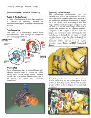
Map <strong>Diagrams</strong><br />
Map diagrams show the entire vehicle wiring circuit. Symbols for components are usually<br />
pictorial meaning the symbol looks like a component it represents. Individual components and<br />
their spatial relationship to one another are not necessarily conveyed as clearly as logical legible<br />
presentation of circuit operation. A variation of the map diagram is the linear diagram. These
use pictorial representations with a mixture of schematic symbols and internal wiring. A linear<br />
diagram may start on one page and continue onto several more a map out individual circuits with<br />
a separate diagram.<br />
Above - A pictorial or map diagram of the electrical system of a 1968 Ford.<br />
Schematic <strong>Diagrams</strong><br />
Schematics are line drawings that explain how a system works by using symbols and connecting<br />
lines. Several different standards for schematic diagrams exit DIN and Valley Forge are the most<br />
common. Symbols are used to represent devices or components of both simple and complex<br />
electrical and electronic systems. Schematic diagrams present a great deal of information in a<br />
small amount of space and the reading of schematic symbols requires practice. A logical, stepby-<br />
step approach to using schematic diagrams for troubleshooting begins with the technician's<br />
understanding of the complete system.<br />
Schematic circuit diagrams may be supplemented with diagrams, tables, graphs or descriptions.<br />
Current path are arranged to show signal or mechanical action from left to right and or top to<br />
bottom. Block diagrams are used to represent complex electronic circuitry such as a electronic<br />
control modules. On these devices, no internal circuitry is shown and only inputs or outputs are<br />
depicted. Dotted lines may represent an area or some mechanical action taking place with a<br />
component The two most common types of schematic diagrams used today are:<br />
� Valley Forge<br />
� DIN (Deutsche Institute Norm)
SAE symbols are used by Valley Forge where DIN symbols are used together with DIN<br />
diagrams.<br />
DIN diagrams are used by many heavy-duty manufacturers. Symbols, terminal connections<br />
numbers, line symbols, operational status in these diagrams are defined by a DIN standard.<br />
These diagrams may be accompanied by illustrations showing internal circuitry of some devices<br />
and reference coordinates used to assist locating components.<br />
Valley Forge wiring diagrams are similar in content to DIN diagrams however SAE coding and<br />
symbol are used. Conductor sizes, symbol representations, component and terminal designations<br />
are different from DIN standards.<br />
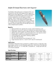
Above – An example of a linear/pictorial wiring diagram.<br />
Vehicles today are wired using sections known as looms or harnesses.<br />
Harnesses are prewired for sections of a vehicle. The harnesses are enclosed into protective<br />
loom and taped so it is not possible to completely trace a single wire to find a problem.<br />
Schematic diagrams are needed to check the circuit at strategic points.
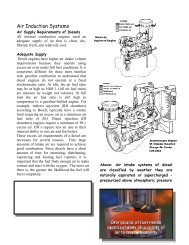
Right –Valley Forge schematic diagram.<br />
Left - Designating a wire by circuit number, harness, colour and diameter.<br />
DIN<br />
Also called “Current Track” wiring diagrams, they show the power source at the top of the page<br />
and the ground points at the bottom. Situated between power and ground are current tracks which<br />
contain electrical components and conductors. This current track layout simplifies the wiring<br />
diagram. Conductor symbols crossing where they do not connect is kept to a minimum.<br />
Power Distribution - Relay Panel<br />
The central/relay panel is indicated in gray at the top of the wiring diagram page. The central/<br />
relay panel includes common power circuits, such as battery power (30), ignition switched power<br />
(15), load reduction (75/X), and ground (31). All ground connections, whether they occur as a<br />
splice in a harness, or the final ground source, are numbered and identified in the wiring<br />
diagram.<br />
Conductors & Components<br />
Between the central/relay panel and the vehicle ground at the bottom of the diagram are located<br />
the component symbols and conductors. Components are marked with a component code listed<br />
in the legend. Conductors are generally marked with wire color and size.<br />
Current Tracks<br />
Individual current tracks are identified numerically along the base of the wiring diagram. These<br />
numbers are used to find the continuation of a conductor. Where the system or circuit layout is<br />
complex, this continuation may be on the same page, or on a different page. For example, the<br />
number 191 inside a small box on one page indicates that the wire is continued on current track<br />
191 on the next page with the same color and size of wire with a small box.
Elements of a <strong>Wiring</strong> Diagram<br />
DIN diagrams are representative of all wiring diagrams in use today. Every circuit needs a<br />
minimum of the following to operate:<br />
� Power supply<br />
� Load<br />
� Ground<br />
� Conductors (usually wire)<br />
� Circuit Protection (Fuse, virtual fuse)<br />
If any of these are missing, a complete circuit is broken and the load will not function. The<br />
ability to break down a circuit into its individual parts is the key to being able to diagnose<br />
failures in the circuit.<br />
<strong>Wiring</strong> diagrams incorporate many symbols used to illustrate a complete circuit. These symbols<br />
can include:<br />
� Current track numbers<br />
� Components<br />
� Terminal designations<br />
� Conductors<br />
� Connectors<br />
Together these components make up a complete and accurate wiring diagram. Graphical<br />
representations called "symbols" are used to represent components and conductors in wiring<br />
diagrams. The key to reading wiring diagrams is understanding the symbols. These symbols are<br />
standardized, allowing quick recognition of various components.
DIN Standard 72 552<br />
This standard applies to the terminal designations for circuits. The purpose of the terminal<br />
designation system is to enable accurate connection identification from conductors (wires) to<br />
various components when diagnosis and repair is necessary. Examples of DIN standards for<br />
terminal designations are:<br />
� 15 Ignition switched on and start<br />
� 30 Battery +<br />
31 Ground[Type a quote from the document or the summary of an interesting point. You can position<br />
the text box anywhere in the document. Use the Text Box Tools tab to change the formatting of the pull<br />
quote text box.]<br />
�<br />
� 31b Switched Ground<br />
� 50 Starter control switched on only<br />
<strong>Wiring</strong><br />
Wires are conductors that carry current to components, and are<br />
usually indicated by a solid line. A wire shown as a dashed line in a<br />
wiring diagram indicates that the wire does not apply to all vehicles<br />
and is noted in the wiring diagram legend.<br />
Wire colors<br />
Knowing the standards for wiring colors makes the job of reading<br />
and interpreting them easier. Some of the common standards<br />
include wiring color for specific circuits, as well as the terminal<br />
designation.<br />
For example:<br />
Red . . . . . . . . . . . . . . . . . . . Battery +<br />
Green. . . . . . . . . . . . . . . . . . Ignition (1)<br />
Brown . . . . . . . . . . . . . . . . . Ground (31)<br />
Yellow . . . . . . . . . . . . . . . . . Headlights (58)<br />
Wire colors are shown as abbreviations of the German word for the color.<br />
bl . . . . . . . . . . . . . . . . . . . . . Blue<br />
br. . . . . . . . . . . . . . . . . . . . . Brown<br />
ge . . . . . . . . . . . . . . . . . . . . Yellow<br />
gn . . . . . . . . . . . . . . . . . . . . Green<br />
ro. . . . . . . . . . . . . . . . . . . . . Red<br />
sw . . . . . . . . . . . . . . . . . . . . Black<br />
li . . . . . . . . . . . . . . . . . . . . . Violet<br />
ws . . . . . . . . . . . . . . . . . . . . White<br />
Wire Gauge Tool
Wire Sizes<br />
<strong>Wiring</strong> diagrams also indicate the wire gauge used (shown in mm2), designating the cross<br />
sectional area of the wire. Because standards exist for the maximum permissible voltage drop<br />
across a circuit, wire gauge is critical. If the voltage drop across the wire is too high, one or more<br />
of the following may occur:<br />
� The circuit may overheat<br />
� The load may not operate properly (due to low voltage condition)<br />
� Components may be damaged<br />
If a wiring repair needs to be made and metric sized wire is not available use American Wire<br />
Gauge (AWG) sized wire.<br />
Note: If the exact size wire is not available for a repair, use the next larger size.<br />
Connector Pin Assignments<br />
<strong>Wiring</strong> diagrams tell the user at which pin numbers the wires terminate, simplifying diagnosis.<br />
There are 4 main types of terminal designations:<br />
� Push-on/multi-point connections<br />
� Component/multi-point<br />
� Central/relay panel<br />
� Relay<br />
Generally, pin assignments are labelled on the plastic hard-shell connector housing and/or the<br />
corresponding component. On larger connectors, pin assignments are labeled at either end of a<br />
row. For example, the Engine Control Module (ECM) plug often has 4 to 10 rows of 12 or more<br />
terminals. Each row will be marked on each end to facilitate easier diagnosis.<br />
Components<br />
Components in wiring diagrams are given an alphanumeric designation for identification. The<br />
first portion of the code separates the component into basic groups. An F for example, designates<br />
a switch, while a Z would be used for a heating element.
Complex Symbols<br />
Often the internal schematic of the component is shown to allow the technician to follow current<br />
flow through the component. These internal symbols are a combination of several basic symbols.<br />
This allows the technician to take a more complex symbol and break it down into its smaller<br />
components. Even the most complex components are nothing more than a combination of<br />
smaller basic symbols. More complex components may contain complex control circuitry. This<br />
will be indicated with the symbol of a transistor in the component symbol (see control module).<br />
A schematic symbol for a control module<br />
A combined component<br />
A relay is an example of a combination of symbols in a single component. Relays require a<br />
signal from an outside source to activate. Relays share the component designator “J” with control<br />
units. The basic 5-pin relay (below) contains two separate components: a switch and a solenoid.<br />
The coil in the solenoid is energized with low current, creating a magnetic pull that closes or<br />
opens the switch.<br />
Note: All switches and relays are shown in a non-operated state.<br />
Relay schematic symbols. Mechanical action is always left to right – note the right relay<br />
switch closes when energized.
DIN Symbols
SAE Symbols
Valley Forge - GM, Ford