PRODUCT CATALOGUE 2012 - Tritec
PRODUCT CATALOGUE 2012 - Tritec
PRODUCT CATALOGUE 2012 - Tritec

You also want an ePaper? Increase the reach of your titles
YUMPU automatically turns print PDFs into web optimized ePapers that Google loves.
energy for a better world<br />
<strong>PRODUCT</strong> <strong>CATALOGUE</strong> <strong>2012</strong>
Foreword<br />
TRITEC means clean energy. The cleanest energy comes<br />
from the sun: today and in the future. “Energy for a better<br />
world” is our motto. This guiding theme includes not only<br />
the environmental aspect, but it also and simultaneously<br />
places an important social demand on the global energy<br />
supply.<br />
For more than 25 years, TRITEC has been an international<br />
photovoltaic system supplier and centre of competence in<br />
the area of renewable energies. All components of a photovoltaic<br />
system must be perfectly coordinated, in order<br />
to achieve optimal efficiency. As your solar specialist and<br />
partner, we will advise and support you in planning your<br />
solar systems. You will find everything regarding technical<br />
advice, product software, documentation and training in<br />
the chapter “Customer Support and Services”.<br />
In addition to the perfect coordination of the individual<br />
PV components, the quality of each individual product is<br />
essential. After all, systems generating solar energy are exposed<br />
to the hardest weather conditions for many years.<br />
For this reason we only use A-brands as we only work with<br />
manufacturers guaranteeing the highest quality. You can<br />
find our products and photovoltaic system components on<br />
page 10 et seqq.<br />
TRITEC is also a system integrator and manufacturer of<br />
own brand products. During the planning and installation<br />
of small and medium-sized photovoltaic systems we work<br />
with qualified partner companies. As international system<br />
integrator we implement large photovoltaic systems and<br />
test state-of-the-art installation technologies, which will<br />
then be established in practical use. To see examples of<br />
our range of applications, please visit www.tritec-energy.<br />
com/reference-cases.<br />
As a manufacturer of proprietary products, we focus on<br />
PV mounting systems and measuring technology. This includes<br />
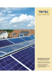
the mounting systems TRI-STAND, TRI-STAND Aero,<br />
TRI-VENT and TRI-ROOF (see chapter “Mounting Systems”),<br />
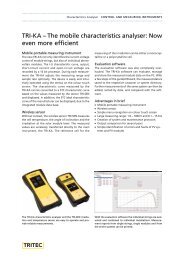
the handy characteristics analyser TRI-KA for the<br />
performance testing of PV systems and the dimensioning<br />
software TRI-DESIGN.<br />
Solar Power Plant 11.6 kWp, Jungfraujoch (Switzerland)<br />
In co-operation with TRITEC<br />
TRI-KA with expanded software tools. There are tools for<br />
the handy characteristics analyser for the performance<br />
testing of installed modules – a system configurator and a<br />
protocol assistant. Using these, any size of PV systems can<br />
be controlled and maintained quickly and efficiently.<br />
Dimensioning software TRI-DESIGN also for inverters. In<br />
addition to roof features, the chosen PV modules and the<br />
appropriate mounting system, inverters can be configured<br />
directly within the programme. This means, just a few<br />
clicks and PV systems can be comprehensively designed<br />
and dimensioned, from the mounting system and inverters<br />
to the string plan.<br />
Do you want to know more about our products?<br />
Get advice or visit a product training course in your area.<br />
Our catalogue is continuously updated; find more information<br />
at: www.tritec-energy.com/products
Contents<br />
PHOTOVOLTAICS<br />
Introduction 7<br />
Grid-connected Systems 8<br />
<strong>PRODUCT</strong>S<br />
Solar Modules 11-31<br />
Grid-connected Inverters 33-65<br />
Control and Measuring Instruments 67-83<br />
Mounting Systems 85-109<br />
Accessories 111-135<br />
Complete Systems 137-141<br />
CUSTOMER SUPPORT AND SERVICES<br />
Product Software 145<br />
Training Courses / Product Documentations 147<br />
COMPANY<br />
General Terms and Conditions 148<br />
TRITEC Contacts 150<br />
Imprint 151
Introduction to Photovoltaics<br />
History of Photovoltaics<br />
Photovoltaics are an essential part of the portfolio of renewable<br />
energies. At the EU level, the passing of the<br />
Directive for Renewable Energies set a mandatory target:<br />
By 2020, 20 per cent of the energy demand must be supplied<br />
by renewable energies. Feed-in tariffs and subsidies<br />
have resulted in a boom in the construction of photovoltaic<br />
installations worldwide. Currently, the 30 GW mark in solar<br />
power output has been exceeded worldwide. That output<br />
can provide 10 million households with clean energy.<br />
And the newly installed photovoltaic output continues to<br />
grow every year. Until 2015, average global growth of<br />
33% per year can be expected.<br />
Already in 1839, the French physicist Alexandre Edmond<br />
Becquerel had discovered the photoelectric effect. But it<br />
took more than 100 years, until the first technical application<br />
in satellite technology could be realised at the end of<br />
the 50s. Driven by the energy crises of the 70s and supported<br />
by an increased environmental awareness, photovoltaics<br />
began to move towards economic efficiency 20<br />
years later.<br />
In a few years, these efforts will result in the so-called grid<br />
parity – the point when power generation using photovoltaics<br />
will be equal in costs to conventional power.<br />
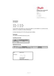
MWp/a<br />
7,5<br />
7,0<br />
6,5<br />
6,0<br />
5,5<br />
5,0<br />
4,5<br />
4,0<br />
3,5<br />
3,0<br />
2,5<br />
2,0<br />
1,5<br />
1,0<br />
0,5<br />
0<br />
1994 1995 1996 1997 1998 1999 2000 2001 2002 2003 2004 2005 2006 2007 2008 2009<br />
Year<br />
Global market volume for photovoltaics systems<br />
© Solarpraxis<br />
Stade de Suisse 1.35 MWp, Bern (Switzerland)<br />
Designed and installed by TRITEC<br />
1,12<br />
1,42<br />
1,60<br />
2,59<br />
5,75<br />
7,20<br />
Potential of Photovoltaics<br />
The amount of sun energy impacting the earth as light and<br />
warmth is 1.5 · 10 18 kWh per annum; this corresponds approximately<br />
to the 15000-fold of the entire primary energy<br />
consumption of humanity in 2006 (1.0 · 10 14 kWh/year). This<br />
irradiation energy can be captured by the photovoltaic<br />
effect and partially converted to electricity, without the<br />
generation of undesirable by-products such as emissions<br />
(e.g. CO 2 ) or nuclear waste.<br />
Central Europe on average can assume an annually irradiated<br />
output of 1000 kWh/m 2 , Southern Europe achieves<br />
values of 1700 kWh/m 2 , some desert regions even more than<br />
2300 kWh/m 2 . If Central Europe wanted to cover the world’s<br />
power needs with the irradiated solar energy, an area of<br />
400 by 400 kilometres would be required.<br />
Global annual solar irradiation in kWh/m²<br />
© meteonorm<br />
7
8<br />
The Functional Principle of the Solar Cell<br />
Today’s solar cells mostly consist of the base material silicon,<br />
that is divided into two layers (p and n layer) with different<br />
electric properties by doping with boron or phosphorus<br />
and thus becomes a diode. In contrast to the conventional<br />
semiconductor diode found in electronic circuits and rectifiers,<br />
the solar cell is optimised to exploit incident sun light.<br />
For this purpose solar cells are manufactured with as large<br />
a surface as possible. The so-called p-n junction here is only<br />
just below the surface exposed to the solar irradiation.<br />
At the p-n junction an electric field is building that has a<br />
pull effect on free (mobile in the material) charge carriers.<br />
The photons (light energy packages) of the incident sun<br />
light penetrate the cell material and now produce free<br />
charge carriers (electrons and holes) in proximity to the p-n<br />
junction. These are separated from the inner field and<br />
swept to the electric connecting contacts on the top and<br />
bottom side of the cell. There they are available for use in<br />
an external circuit. Each cell has a usable voltage of 0.5 to<br />
0.6 Volt, which can be increased to any value by connecting<br />
several cells in series. In solar modules the cells are partially<br />
connected in series and parallel, in order to achieve the optimum<br />
usable operating voltages.<br />
The production rate of the free charge carriers increases in<br />
proportion to the intensity of the solar irradiation. The<br />
photons’ energy is converted to electric power to the<br />
amount of approx. 15 % corresponding to the cell’s efficiency.<br />
The rest heats the solar cell and is discharged to the environment<br />
by means of heat transport processes. At standard<br />
test conditions (STC: 1000 W/m 2 , temperature 25° C,<br />
AirMass 1.5) up to 2.5 Ampere solar power and therefore<br />
approx. 1.5 W electric peak capacity can be expected per<br />
dm 2 of cell surface.<br />
Due to their energy and material efficiency and therefore<br />
due to their lower costs, thin-film technologies show the<br />
greatest potential in the long term. Currently three different<br />
technologies are on the market: the amorphous/microcrystalline<br />
silicon technology, the CdTe based technology<br />
and the copper indium selenide (CIS) technology. Though<br />
these technologies are still in their infancy, manufacturers<br />
are working flat out on their development.<br />
Yield of a Photovoltaic Installation<br />
The yield generated by a photovoltaic installation during a<br />
year is also called solar yield. A significant factor for the<br />
yield assessment of photovoltaic installations is the performance<br />
ratio. For this the yield of the photovoltaic installation<br />
is divided by the installed photovoltaic output and<br />
the annual irradiation. A performance ratio of more than<br />
80 % indicates a good ratio of yield and irradiated solar output.<br />
Among the factors affecting the yield are the location<br />
of the photovoltaic installation, the orientation and the<br />
climate or the intensity and length of the solar irradiation.<br />
By means of special diagrams, the solar irradiation can be<br />
calculated depending on the mounting angle and the orientation.<br />
In Central Europe the solar irradiation is greatest<br />
at an orientation to the South and an angle of 30°. A system<br />
with orientation to the South-West and a mounting<br />
angle of 30° for example, would achieve an annual solar<br />
irradiation of approx. 95 % of the maximum.<br />
In order to enable photovoltaic installations to achieve<br />
high yields, detailed planning is necessary. On the one<br />
hand the used components must be adapted perfectly to<br />
the individual requirements, and on the other attention<br />
must be given to correct dimensioning and placement with<br />
the least possible clouding. In addition, solar modules are<br />
daily exposed to wind and weather and must work faultlessly<br />
in spite of all adversities. Therefore, high-quality and<br />
durable products are another important prerequisite for<br />
good yields of photovoltaic systems.<br />
Grid-connected<br />
Photovoltaic Systems<br />
Design of Grid-connected Photovoltaic<br />
Installations<br />
Grid-connected systems are photovoltaic installations that<br />
are connected to the public grid and feed the entire electric<br />
power generated by the solar energy to the grid. The size<br />
of a grid-connected system depends on different factors:<br />
roof/facade surface, financial resources and statutory provisions.<br />
Most European private grid-connected systems have<br />
an output of two to ten kilowatt. If an installation on a<br />
pitched roof is supposed to achieve such a yield, the required<br />
roof surface for two kilowatt (PV) is approximately<br />
18 m 2 and approximately 90 m 2 for ten kilowatt.<br />
The essential components of grid-connected PV installation<br />
are photovoltaic modules, inverters, a mounting system, a<br />
protective device to automatically switch off in case of<br />
mains malfunctions and a meter to record the amount of<br />
power supplied. Two factors are essential for a high-yield<br />
system: 1. The quality of the installed products, incl. accessories<br />
(e.g. wiring); 2. The different components must be<br />
optimally coordinated.<br />
For 25 years now, TRITEC has been a photovoltaic system<br />
provider with a wide and premium range of quality products.<br />
We are happy to support you in the planning as well<br />
as in case of queries regarding the approval and financing<br />
of photovoltaic installations.
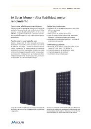
Functional principle of a crystalline solar cell © Solarpraxis<br />
Annual irradiation (%) © DGS / Solarpraxis<br />
8<br />
7<br />
4<br />
6 5<br />
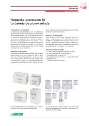
Principle of a grid-connected photovoltaic system © Solarpraxis<br />
3<br />
1<br />
2<br />
1. PV array<br />
2. Mounting system<br />
3. Wiring<br />
4. PV array combiner/junction box<br />
5. Grid-connected inverter<br />
6. Import/export meter<br />
7. Connection to grid<br />
8. Consumer loads<br />
9
Solar Modules<br />
We offer solar modules of the latest generation: for<br />
gridintegrated equipment, stand-alone solutions,<br />
emergency power supply, pumping systems, solar power<br />
plants, telecommunication or traffic signals.<br />
BOSCH<br />
HAREON SOLAR<br />
KYOCERA<br />
PANASONIC<br />
SANYO<br />
SCHOTT SOLAR<br />
SUNTECH<br />
11
12<br />
...................................................................................................................................................................<br />
SOLAR MODULES Framed Modules<br />
...................................................................................................................................................................<br />
Bosch Mono series – High quality, powerful and<br />
reliable<br />
Bosch Solar Energy<br />
Bosch is a household name across the world symbolising<br />
decades of tradition, technical expertise and<br />
international presence. Bosch Solar Energy stands for<br />
the claim of providing excellent value for money for<br />
first-rate product quality and reliability. Bosch Solar<br />
Energy covers the entire photovoltaics value chain –<br />
from drawing ingots all the way to module production.<br />
Production sites: Germany, Spain and France.<br />
Excellent product quality<br />
Bosch Solar Energy delivers superior solar cells and<br />
modules with high annual yields. This requires cutting-edge<br />
production equipment and excellent processes.<br />
Periodically calibrated measuring instruments<br />
ensure reliable output measurements under STC. The<br />
cells are measured for output based on the current IEC<br />
60904 and IEC 60981 standards. In addition, the modules<br />
are subjected to a thorough reverse current resistance<br />
check exhibiting a very low reverse current of<br />
...................................................................................................................................................................<br />
Framed Modules SOLAR MODULES<br />
...................................................................................................................................................................<br />
Art. No.* 0101372 0101374 0101375<br />
Model Bosch Solar M195 3BB c‑Si Mono 48 Bosch Solar M240 3BB c‑Si Mono 60 Bosch Solar M245 3BB c‑Si Mono 60<br />
Nominalpower 195W+4.99W,-0W 240W+4.99W,-0W 245W+4.99W,-0W<br />
Max. system voltage 1000 V 1000 V 1000 V<br />
Operating voltage 24.3 V 30.0 V 30.1 V<br />
Operating current 8.05 A8.10 A8.20 A<br />
Open circuit voltage 29.5 V 37.4 V 37.7 V<br />
Short circuit current 8.65 A8.60 A8.70 A<br />
Temp. coefficient voltage -100.3 mV/°C, -0.34 %/K -119.68 mV/°C, -0.32 %/K -120.64 mV/°C, -0.32 %/K<br />
Temp. coefficient current 3.03 mA/°C, 0.035 %/K 2.75 mA/°C, 0.032 %/K 2.78 mA/°C, 0.032 %/K<br />
Reverse current load 17 A17 A17 A<br />
Max. string protection 17 A17 A17 A<br />
Number of bypass diodes 3 pc. 3 pc. 3 pc.<br />
Cells per module 48 pc. 60 pc. 60 pc.<br />
Cell dimensions (L / W) 156 mm / 156 mm 156 mm / 156 mm 156 mm / 156 mm<br />
Cell connection 3 bus bar 3 bus bar 3 bus bar<br />
Cell technology Monocrystalline silicon Monocrystalline silicon Monocrystalline silicon<br />
Connection MC-PV4, cables, 1000 (–) / 1000 (+) mm MC-PV4, cables, 800 (–) / 1200 (+) mm MC-PV4, cables, 800 (–) /1200(+)mm<br />
Mounting frame Anodized aluminium Anodized aluminium Anodized aluminium<br />
Dimensions (L / W / H) 1342 mm / 990 mm / 50 mm 1660 mm / 990 mm / 50 mm 1660 mm / 990 mm / 50 mm<br />
Weight 16 kg 21 kg 21 kg<br />
Number per container 450 pc. 450 pc. 450 pc.<br />
Max. load 5400 N/m² 5400 N/m² 5400 N/m²<br />
Performance warranty ** 10 / 25 years 10 / 25 years 10 / 25 years<br />
Product warranty 10 years 10 years 10 years<br />
Norms IEC 61215 ed. 2, IEC 61730, TÜVdotCOM-<br />
ID: 0000026647, MCS, PV CYCLE<br />
IEC 61215 ed. 2, IEC 61701, IEC 61730,<br />
TÜVdotCOM-ID: 0000026647, MCS, PV<br />
CYCLE<br />
IEC 61215 ed. 2, IEC 61701, IEC 61730,<br />
TÜVdotCOM-ID: 0000026647, MCS, PV<br />
CYCLE<br />
* - Art. No. 0101374: Minimum order quantity of 1 container<br />
** - Manufacturer's performance warranty: 10 years on 90 % / 25 years on 80 % of the minimal nominal power under standard testing conditions (STC)<br />
The electrical specifications are under standard test conditions (STC) of irradiance of 1000 W/m², spectrumof1.5airmassandcelltemperatureof25°C.<br />
TRITEC Group www.tritec-energy.com | © <strong>2012</strong>1214-1 | The content of this datasheet is subject to change without prior notice<br />
13
14<br />
...................................................................................................................................................................<br />
SOLAR MODULES Framed Modules<br />
...................................................................................................................................................................<br />
Hareon Solar HR-Mono – The new modules with<br />
monocrystalline cells<br />
Hareon Solar<br />
Since its foundation in 2004, Hareon Solar has developed<br />
rapidly and become one of the largest suppliers<br />
of silicon wafers in China. Due to the specific manufacture<br />
of solar cells and solar modules by Hareon's subsidiaries<br />
Jiangyin Hareon Power Co., Ltd. and Altusvia<br />
Energy Co., Ltd., Hareon Solar has a complete vertical<br />
production chain. Continuous improvement of manufacturing<br />
processes and continual raising of quality<br />
standards enable Hareon Solar to supply their customers<br />
with optimal solar modules.<br />
HR-Mono series<br />
With a module efficiency of up to 15.7 % and a cell<br />
efficiencyofupto17.9%, the modules of the series HR-<br />
Mono achieve very high efficiencies. Even with less<br />
exposure of light the modules achieve a good energy<br />
yield, due to their excellent low-light properties. In<br />
addition to their outstanding technical data, the modules<br />
also meet high visual requirements.<br />
The solar modules manufactured by Hareon Solar have been<br />
tested and certified by all recognised test institutes worldwide.<br />
Best quality<br />
Through mechanical load tests and flash tests Hareon<br />
Solar guarantees the highest quality in the long term.<br />
Not only the certifications according to CE, UL, CEC, IEC,<br />
RoHS and ISO, but also the long product and performance<br />
warranty attest to the high quality of Hareon<br />
Solar modules. In addition to the ten-year product<br />
warranty, the manufacturer guarantees a module performance<br />
of 90 % of the nominal output for 12 years<br />
and of 80 % for 25 years.<br />
Advantages in brief<br />
n Complete vertical production chain from the raw<br />
silicon to the module<br />
n Leading production capacity<br />
n High efficiency<br />
n Long product and performance warranty<br />
The Ningbo plugs allow easy wiring of the modules, while<br />
the specifically developed module frames withstand loads<br />
of up to 5400 N/m².
...................................................................................................................................................................<br />
Framed Modules SOLAR MODULES<br />
...................................................................................................................................................................<br />
Art. No.* 0101356 0101354 0101437<br />
Model Hareon HR-195W Mono Hareon HR-200W Mono Hareon HR-250W-18/Cbb Mono<br />
Nominalpower 195W+5W,-0W 200W+5W,-0W 250W+5W,-0W<br />
Max. system voltage 1000 V 1000 V 1000 V<br />
Operating voltage 36.94 V 37.39 V 30.59 V<br />
Operating current 5.28 A5.35 A8.17 A<br />
Open circuit voltage 45.28 V 45.50 V 37.59 V<br />
Short circuit current 5.58 A5.79 A8.79 A<br />
Temp. coefficient open circuit<br />
voltage<br />
-0.31 %/K -0.31 %/K -0.31 %/K<br />
Temp. coefficient short circuit<br />
current<br />
0.047 %/K 0.047 %/K 0.047 %/K<br />
Temp. coefficient nominal<br />
power<br />
-0.41 %/K -0.41 %/K -0.41 %/K<br />
Reverse current load 15 A15 A15 A<br />
Max. string protection 15 A15 A15 A<br />
Number of bypass diodes 3 pc. 3 pc. 3 pc.<br />
Cells per module 72 pc. 72 pc. 60 pc.<br />
Cell dimensions (L / W) 125 mm / 125 mm 125 mm / 125 mm 156 mm / 156 mm<br />
Cell connection 2 bus bar 2 bus bar 3 bus bar<br />
Cell technology Monocrystalline silicon Monocrystalline silicon Monocrystalline silicon<br />
Connection Ningbo, cable 900 mm each (+ / ‑) Ningbo, cable 900 mm each (+ / ‑) Ningbo, cable 1000 mm each (+ / ‑)<br />
Mounting frame Anodized aluminium Anodized aluminium Black anodized aluminium<br />
Back sheet White White Black<br />
Dimensions (L / W / H) 1580 mm / 808 mm / 45 mm 1580 mm / 808 mm / 45 mm 1636 mm / 992 mm / 45 mm<br />
Weight 16.0 kg 16.0 kg 19.5 kg<br />
Number per container 616 pc. 616 pc. 616 pc.<br />
Max. load 5400 N/m² 5400 N/m² 5400 N/m²<br />
Performance warranty ** 12 / 25 years 12 / 25 years 12 / 25 years<br />
Product warranty 10 years 10 years 10 years<br />
Norms IEC 61215, IEC 61730, CE, UL Listed, CEC,<br />
RoHS, ISO 9001, ISO 14001, TÜVdotCOM-<br />
ID: 0000026038, MCS, PV CYCLE<br />
IEC 61215, IEC 61730, CE, UL Listed, CEC,<br />
RoHS, ISO 9001, ISO 14001, TÜVdotCOM-<br />
ID: 0000026038, MCS, PV CYCLE<br />
IEC 61215, IEC 61730, CE, UL Listed, CEC,<br />
RoHS, ISO 9001, ISO 14001, TÜVdotCOM-<br />
ID: 0000026038, MCS, PV CYCLE<br />
* - Art. No. 0101354 / 0101437: Minimum order quantity of 1 container<br />
** - Manufacturer's performance warranty: 12 years on 90 % / 25 years on 80 % of the minimal nominal power under standard testing conditions (STC)<br />
The electrical specifications are under standard test conditions (STC) of irradiance of 1000 W/m², spectrumof1.5airmassandcelltemperatureof25°C.<br />
TRITEC Group www.tritec-energy.com | © <strong>2012</strong>1214-1 | The content of this datasheet is subject to change without prior notice<br />
15
16<br />
...................................................................................................................................................................<br />
SOLAR MODULES Framed Modules<br />
...................................................................................................................................................................<br />
Hareon Solar HR-Poly – The new modules with<br />
polycrystalline 6" cells<br />
Hareon Solar<br />
Since its foundation in 2004, Hareon Solar has developed<br />
rapidly and become one of the largest suppliers<br />
of silicon wafers in China. Due to the specific manufacture<br />
of solar cells and solar modules by Hareon's subsidiaries<br />
Jiangyin Hareon Power Co., Ltd. and Altusvia<br />
Energy Co., Ltd., Hareon Solar has a complete vertical<br />
production chain. Continuous improvement of manufacturing<br />
processes and continual raising of quality<br />
standards enable Hareon Solar to supply their customers<br />
with optimal solar modules.<br />
HR-Poly series<br />
With a module efficiency of up to 15.1 % and a cell<br />
efficiencyofupto16.7%, the modules of the series HR-<br />
Poly achieve very high efficiencies. Even with less exposure<br />
of light the modules achieve a good energy yield,<br />
due to their excellent low-light properties. In addition<br />
to their outstanding technical data, the modules also<br />
meet high visual requirements.<br />
The HR-Poly of Hareon Solar with 3 bus bar cells have been<br />
tested and certified by all recognised test institutes worldwide.<br />
Best quality<br />
Through mechanical load tests and flash tests Hareon<br />
Solar guarantees the highest quality in the long term.<br />
Not only the certifications according to CE, UL, CEC, IEC,<br />
RoHS and ISO, but also the long product and performance<br />
warranty attest to the high quality of Hareon<br />
Solar modules. In addition to the ten-year product<br />
warranty, the manufacturer guarantees a module performance<br />
of 90 % of the nominal output for 12 years<br />
and of 80 % for 25 years.<br />
Advantages in brief<br />
n Complete vertical production chain from the raw<br />
silicon to the module<br />
n Leading production capacity<br />
n High efficiency<br />
n Long product and performance warranty<br />
n New 3 bus bar cell technology<br />
With their Ningbo connectors and the specifically developed<br />
45 mm frame (loads up to 5400 N/m²), the Hareon solar<br />
modules are suitable for universal applications.
...................................................................................................................................................................<br />
Framed Modules SOLAR MODULES<br />
...................................................................................................................................................................<br />
Art. No.* 0101339 0101408<br />
Model Hareon HR-240W Poly Hareon HR-245W Poly<br />
Nominal power 240 W +5 W, -0 W 245 W +5 W, -0 W<br />
Max. system voltage 1000 V 1000 V<br />
Operating voltage 28.98 V 29.11 V<br />
Operating current 8.28 A8.42 A<br />
Open circuit voltage 37.14 V 37.23 V<br />
Short circuit current 8.69 A8.85 A<br />
Temp. coefficient open circuit<br />
voltage<br />
-0.32 %/K -0.32 %/K<br />
Temp. coefficient short circuit<br />
current<br />
0.055 %/K 0.055 %/K<br />
Temp. coefficient nominal<br />
power<br />
-0.44 %/K -0.44 %/K<br />
Reverse current load 15 A15 A<br />
Max. string protection 15 A15 A<br />
Number of bypass diodes 3 pc. 3 pc.<br />
Cells per module 60 pc. 60 pc.<br />
Cell dimensions (L / W) 156 mm / 156 mm 156 mm / 156 mm<br />
Cell connection 3 bus bar 3 bus bar<br />
Cell technology Polycrystalline silicon Polycrystalline silicon<br />
Connection Ningbo, cable 1000 mm each (+ / ‑) Ningbo, cable 1000 mm each (+ / ‑)<br />
Mounting frame Anodized aluminium Anodized aluminium<br />
Dimensions (L / W / H) 1636 mm / 992 mm / 45 mm 1636 mm / 992 mm / 45 mm<br />
Weight 19.5 kg 19.5 kg<br />
Number per container 616 pc. 616 pc.<br />
Max. load 5400 N/m² 5400 N/m²<br />
Performance warranty ** 12 / 25 years 12 / 25 years<br />
Product warranty 10 years 10 years<br />
Norms IEC 61215, IEC 61730, CE, UL Listed, CEC, RoHS, ISO 9001, ISO<br />
14001, TÜVdotCOM-ID: 0000026038, MCS, PV CYCLE<br />
IEC 61215, IEC 61730, CE, UL Listed, CEC, RoHS, ISO 9001, ISO<br />
14001, TÜVdotCOM-ID: 0000026038, MCS, PV CYCLE<br />
* - Art. No. 0101408: Minimum order quantity of 1 container<br />
** - Manufacturer's performance warranty: 12 years on 90 % / 25 years on 80 % of the minimal nominal power under standard testing conditions (STC)<br />
The electrical specifications are under standard test conditions (STC) of irradiance of 1000 W/m², spectrumof1.5airmassandcelltemperatureof25°C.<br />
TRITEC Group www.tritec-energy.com | © <strong>2012</strong>1214-1 | The content of this datasheet is subject to change without prior notice<br />
17
18<br />
...................................................................................................................................................................<br />
SOLAR MODULES Framed Modules<br />
...................................................................................................................................................................<br />
The KD series – Large-area high performance<br />
modules<br />
Advanced technology<br />
Thanks to Kyocera's advanced cell processing technology,<br />
intensive research and automated production<br />
facilities they are able to produce a highly efficient<br />
polycrystalline photovoltaic module.<br />
High efficiency<br />
The embedded Kyocera high-performance solar cells<br />
with the basic measurement 156 x 156 mm achieve an<br />
efficiencyofover16% and guarantee an extremely<br />
high annual energy output of the photovoltaic plant.<br />
Improved aluminium frame<br />
These cells are encapsulated between a tempered glass<br />
cover (resistance to impact of hail acc. to IEC 61215 ed.<br />
2testedbytheTÜV – Technical Control Association)<br />
and an EVApottant with back sheet to provide efficient<br />
protection from the severest environmental conditions.<br />
The entire laminate is installed in an anodized<br />
aluminum frame to provide structural strength and<br />
The new KD series from Kyocerawith increased efficiency<br />
and performance.<br />
ease of mounting, which now has a height of 46 mm<br />
and can tolerate stresses of up to 5400 N/m².<br />
The connecting box on the back is provided with<br />
bypass diodes preventing the risk of overheating of<br />
individual solar cells (hot spot effect). Several PV modules<br />
connected in series can easily be wired up using<br />
pre-assembled solar cables and plugs.<br />
Kyocera manufactures all components in its own manufacturing<br />
plants – without the acquisition of semi<br />
finished products – for a constantly high quality of its<br />
products.<br />
Range of application<br />
n Private residences<br />
n Industrial and large plants<br />
n Agricultural operations<br />
n Free-standing plants<br />
n Solar energy plants<br />
Thanks to the textured silicon nitride, the 6" cell receives a<br />
minor light reflection and homogeneous coloration.
...................................................................................................................................................................<br />
Framed Modules SOLAR MODULES<br />
...................................................................................................................................................................<br />
Art. No.* 0101429 0101297 0101430 0101425 0101286 0101426<br />
Model KD140GH-2YU KD190GH-2PU KD190GH-2YU KD220GH-2YU KD245GH-2PB KD245GH-4YB<br />
Nominal power 140 W ±5 % 190 W ±5 % 190 W ±5 % 220 W +5 %, -3% 245 W +5 %, -3% 245 W +5 %, -3%<br />
Max. system voltage 1000 V 1000 V 1000 V 1000 V 1000 V 1000 V<br />
Operating voltage 17.70 V 23.60 V 23.60 V 26.60 V 29.80 V 29.80 V<br />
Operating current 7.91 A8.06 A8.06 A8.28 A8.23 A8.23 A<br />
Open circuit voltage 22.10 V 29.50 V 29.50 V 33.20 V 36.90 V 36.90 V<br />
Short circuit current 8.68 A8.82 A8.82 A8.98 A8.91 A8.91 A<br />
Temp. coefficient open circuit -79.56 mV/K, -106.2 mV/K, -106.2 mV/K, -119.52 mV/K, -132.84 mV/K, -132.84 mV/K,<br />
voltage<br />
‑0.36 %/K<br />
‑0.36 %/K<br />
‑0.36 %/K<br />
‑0.36 %/K<br />
‑0.36 %/K<br />
‑0.36 %/K<br />
Temp. coefficient short circuit 5.208 mA/K, 5.292 mA/K, 5.292 mA/K, 5.388 mA/K, 5.346 mA/K, 5.346 mA/K,<br />
current<br />
0.06 %/K<br />
0.06 %/K<br />
0.06 %/K<br />
0.06 %/K<br />
0.06 %/K<br />
0.06 %/K<br />
Temp. coefficient nominal -644 mW/K, -874 mW/K, -874 mW/K, -1012 mW/K, -1127 mW/K, -1127 mW/K,<br />
power<br />
‑0.46 %/K<br />
‑0.46 %/K<br />
‑0.46 %/K<br />
‑0.46 %/K<br />
‑0.46 %/K<br />
‑0.46 %/K<br />
Reverse current load 15 A15 A15 A15 A15 A15 A<br />
Max. string protection 15 A15 A15 A15 A15 A15 A<br />
Numberofbypassdiodes2pc. 3pc. 3pc. 3pc. 3pc. 3pc.<br />
Cells per module 36 pc. 48 pc. 48 pc. 54 pc. 60 pc. 60 pc.<br />
Cell dimensions (L / W) 156 mm / 156 mm 156 mm / 156 mm 156 mm / 156 mm 156 mm / 156 mm 156 mm / 156 mm 156 mm / 156 mm<br />
Cell connection 3 bus bar 3 bus bar 3 bus bar 3 bus bar 3 bus bar 3 bus bar<br />
Cell technology Polycrystalline sili- Polycrystalline sili- Polycrystalline sili- Polycrystalline sili- Polycrystalline sili- Polycrystalline siliconconconconconcon<br />
Connection MC PV-KBT3 / MC MC PV-KBT3 / MC MC PV-KBT3 / MC MC PV-KBT3 / MC MC PV-KBT3 / MC SMK PV-03, cables,<br />
PV-KST3, cables, PV-KST3, cables, PV-KST3, cables, PV-KST3, cables, PV-KST3, cables, 960 (–) / 1190 (+) mm<br />
840 (–) / 1010 (+) mm 840 (–) / 1030 (+) mm 840 (–) / 1030 (+) mm 960 (–) / 1190 (+) mm 960 (–) / 1190 (+) mm<br />
Mounting frame Black anodized Black anodized Black anodized Black anodized Black anodized Black anodized<br />
aluminium aluminium aluminium aluminium aluminium aluminium<br />
Dimensions (L / W / H) 1500 mm / 668 mm / 1338 mm / 990 mm / 1338 mm / 990 mm / 1500 mm / 990 mm / 1662 mm / 990 mm / 1662 mm / 990 mm /<br />
46 mm<br />
46 mm<br />
46 mm<br />
46 mm<br />
46 mm<br />
46 mm<br />
Weight 12.5 kg 16.0 kg 16.0 kg 18.0 kg 21.0 kg 21.0 kg<br />
Number per container 960 pc. 760 pc. 760 pc. 680 pc. 600 pc. 600 pc.<br />
Max. load 5400 N/m² 5400 N/m² 5400 N/m² 5400 N/m² 5400 N/m² 5400 N/m²<br />
Performance warranty ** 10 / 20 (25) years 10 / 20 (25) years 10 / 20 (25) years 10 / 20 (25) years 10 / 20 (25) years 10 / 20 (25) years<br />
Product warranty 10 years 10 years 10 years 10 years 10 years 10 years<br />
Norms IEC 61215 ed. 2, IEC IEC 61215 ed. 2, IEC IEC 61215 ed. 2, IEC IEC 61215 ed. 2, IEC IEC 61215 ed. 2, IEC IEC 61215 ed. 2, IEC<br />
61730, protection 61730, protection 61730, protection 61730, protection 61730, protection 61730, protection<br />
class II,<br />
class II,<br />
class II,<br />
class II,<br />
class II,<br />
class II,<br />
TÜVdotCOM-ID: TÜVdotCOM-ID: TÜVdotCOM-ID: TÜVdotCOM-ID: TÜVdotCOM-ID: TÜVdotCOM-ID:<br />
0000023299, MCS, 0000023299, MCS, 0000023299, MCS, 0000023299, MCS, 0000023299, MCS, 0000023299, MCS,<br />
PV CYCLE<br />
PV CYCLE<br />
PV CYCLE<br />
PV CYCLE<br />
PV CYCLE<br />
PV CYCLE<br />
* - Art. No. 0101429: Minimum order quantity of 1 container<br />
** - Manufacturer's performance warranty: 10 years on 90 % / 20 years on 80 % of the minimal nominal power under standard testing conditions (STC) –<br />
SPECIAL PROMOTION: 25 years on 80 % on orders from 15/09/2011<br />
The electrical specifications are under standard test conditions (STC) of irradiance of 1000 W/m², spectrumof1.5airmassandcelltemperatureof25°C.<br />
TRITEC Group www.tritec-energy.com | © <strong>2012</strong>1214-1 | The content of this datasheet is subject to change without prior notice<br />
19
20<br />
...................................................................................................................................................................<br />
SOLAR MODULES Framed Modules<br />
...................................................................................................................................................................<br />
Panasonic HIT modules – With powerful HIT solar<br />
cells<br />
HIT solar cells<br />
All modules are equipped with the new HIT solar cell<br />
technology. The Panasonic HIT solar cell (Heterojunction<br />
with Intrinsic Thin layer) consists of monocrystalline<br />
hybrid wafers coated with thin amorphous silicon.<br />
The modern manufacturing process allows for the<br />
manufacture of solar cells with the highest levels of<br />
efficiency and optimum energy yields.<br />
High efficiency<br />
In commercial solar products worldwide, HIT solar cells<br />
achieve one of the highest efficiencies. Compared to<br />
The modules of the Panasonic HIT-N series are based on<br />
hybrid HIT solar cells (amorphous and monocrystalline silicon)<br />
with the highest levels of efficiency.<br />
conventional solar cells with crystalline silicon, the HIT<br />
cells convince with their high energy yield, even at high<br />
temperatures.<br />
Advantages in brief<br />
n Highest level of efficiency<br />
n Maximum energy yields<br />
n More output per surface<br />
n Small dimensions<br />
The series Panasonic HIT-H employs HD-HIT solar cells, which<br />
optimally exploit the raw material silicon, due to their geometric<br />
design.
...................................................................................................................................................................<br />
Framed Modules SOLAR MODULES<br />
...................................................................................................................................................................<br />
Art. No. 0101419 0101420<br />
Model Panasonic VBHN235SE10 Panasonic VBHH250AE01<br />
Nominal power 235 W +10 %, -5% 250 W +10 %, -5%<br />
Max. system voltage 1000 V 1000 V<br />
Operating voltage 43.0 V 34.9 V<br />
Operating current 5.48 A7.18 A<br />
Open circuit voltage 51.8 V 43.1 V<br />
Short circuit current 5.84 A7.74 A<br />
Temp. coefficient power -0.30 %/°C -0.30 %/°C<br />
Temp. coefficient voltage -130 mV/°C -109 mV/°C<br />
Temp. coefficient current 1.75 mA/°C 2.21 mA /°C<br />
Reverse current load 15 A15 A<br />
Cells per module 72 pc. 60 pc.<br />
Cell type HIT solar cell, monocrystalline HIT solar cell, monocrystalline<br />
Cell dimensions 125 / 125 mm Ø 166 mm<br />
Connection SMK connectors, cable 960 mm each (+ / ‑) SMK connectors, cable 1150 mm each (+ / ‑)<br />
Mounting frame Black anodized aluminium Black anodized aluminium<br />
Dimensions(L/W/H) 1580mm±2mm / 798 mm ±2 mm/35mm±1mm 1610 mm ±2 mm/861mm±2 mm/35mm±1 mm<br />
Weight 15.0 kg (approx.) 16.5 kg (approx.)<br />
Number per container 960 pc. 600 pc.<br />
Max. load 2400 N/m² 2400 N/m²<br />
Performance warranty * 10 / 25 years 10 / 20 years<br />
Product warranty 10 years 10 years<br />
Norms IEC 61730, IEC 61215, CE mark, protection class II, TÜVdotCOM-<br />
ID: 0000023431, MCS, PV CYCLE<br />
IEC 61730, IEC 61215, CE mark, protection class II, TÜVdotCOM-<br />
ID: 0000023431, MCS, PV CYCLE<br />
* - Manufacturer's performance warranty: 10 years on 90 % /20or25yearson80% of the minimal nominal power under standard testing conditions<br />
(STC)<br />
The electrical specifications are under standard test conditions (STC) of irradiance of 1000 W/m², spectrumof1.5airmassandcelltemperatureof25°C.<br />
At very high module temperatures the HIT solar cells<br />
generate clearly higher outputs, compared to monocrystalline<br />
cells.<br />
The special HD (Honeycomb Design) HIT solar cells require<br />
less silicon per Wp, which reduces the amortisation period.<br />
TRITEC Group www.tritec-energy.com | © <strong>2012</strong>1214-1 | The content of this datasheet is subject to change without prior notice<br />
21
22<br />
...................................................................................................................................................................<br />
SOLAR MODULES Framed Modules<br />
...................................................................................................................................................................<br />
Sanyo HIT modules – With powerful HIT solar cells<br />
HIT solar cells<br />
All modules are equipped with the new HIT solar cell<br />
technology. The Sanyo HIT solar cell (Heterojunction<br />
with Intrinsic Thin layer) consists of monocrystalline<br />
hybrid wafers coated with thin amorphous silicon.<br />
The modern manufacturing process allows for the<br />
manufacture of solar cells with the highest levels of<br />
efficiency and optimum energy yields.<br />
High efficiency<br />
In commercial solar products worldwide, HIT solar cells<br />
achieve one of the highest efficiencies. Compared to<br />
The modules of the Sanyo HIT-N series are based on hybrid<br />
HIT solar cells (amorphous and monocrystalline silicon) with<br />
the highest levels of efficiency.<br />
conventional solar cells with crystalline silicon, the HIT<br />
cells convince with their high energy yield, even at high<br />
temperatures.<br />
Advantages in brief<br />
n Highest level of efficiency<br />
n Maximum energy yields<br />
n More output per surface<br />
n Small dimensions<br />
The series Sanyo HIT-H employs HD-HIT solar cells, which<br />
optimally exploit the raw material silicon, due to their geometric<br />
design.
...................................................................................................................................................................<br />
Framed Modules SOLAR MODULES<br />
...................................................................................................................................................................<br />
Art. No. 0101248 0101250<br />
Model Sanyo HIT-N235SE10 Sanyo HIT-H250E01<br />
Nominal power 235 W +10 %, -5% 250 W +10 %, -5%<br />
Max. system voltage 1000 V 1000 V<br />
Operating voltage 43.0 V 34.9 V<br />
Operating current 5.48 A7.18 A<br />
Open circuit voltage 51.8 V 43.1 V<br />
Short circuit current 5.84 A7.74 A<br />
Temp. coefficient power -0.30 %/°C -0.30 %/°C<br />
Temp. coefficient voltage -130 mV/°C -109 mV/°C<br />
Temp. coefficient current 1.75 mA/°C 2.21 mA /°C<br />
Reverse current load 15 A15 A<br />
Cells per module 72 pc. 60 pc.<br />
Cell type HIT solar cell, monocrystalline HIT solar cell, monocrystalline<br />
Cell dimensions 125 / 125 mm Ø 166 mm<br />
Connection MC3 connectors, cable 960 mm each (+ / ‑) MC3 connectors, cable 1150 mm each (+ / ‑)<br />
Mounting frame Black anodized aluminium Black anodized aluminium<br />
Dimensions(L/W/H) 1580mm±2mm / 798 mm ±2 mm/35mm±1mm 1610 mm ±2 mm/861mm±2 mm/35mm±1 mm<br />
Weight 15.0 kg (approx.) 16.5 kg (approx.)<br />
Number per container 960 pc. 600 pc.<br />
Max. load 2400 N/m² 2400 N/m²<br />
Performance warranty * 10 / 25 years 10 / 20 years<br />
Product warranty 10 years 10 years<br />
Norms IEC 61730, IEC 61215, CE mark, protection class II, TÜVdotCOM-<br />
ID: 0000023431, MCS, PV CYCLE<br />
IEC 61730, IEC 61215, CE mark, protection class II, TÜVdotCOM-<br />
ID: 0000023431, MCS, PV CYCLE<br />
* - Manufacturer's performance warranty: 10 years on 90 % /20or25yearson80% of the minimal nominal power under standard testing conditions<br />
(STC)<br />
The electrical specifications are under standard test conditions (STC) of irradiance of 1000 W/m², spectrumof1.5airmassandcelltemperatureof25°C.<br />
At very high module temperatures the HIT solar cells<br />
generate clearly higher outputs, compared to monocrystalline<br />
cells.<br />
The special HD (Honeycomb Design) HIT solar cells require<br />
less silicon per Wp, which reduces the amortisation period.<br />
TRITEC Group www.tritec-energy.com | © <strong>2012</strong>1214-1 | The content of this datasheet is subject to change without prior notice<br />
23
24<br />
...................................................................................................................................................................<br />
SOLAR MODULES Framed Modules<br />
...................................................................................................................................................................<br />
Schott Protect ASI Series – The next generation<br />
Schott Protect ASI technology<br />
Schott Protect ASI thin-film solar modules guarantee<br />
an above average high performance and energy yield.<br />
More energy, the robust encapsulation, the quick and<br />
easy installation and the top safety – all these are<br />
features contributing to the top quality of the ASI<br />
modules.<br />
Proven and tested quality<br />
Only the highest quality of the individual components<br />
can achieve the highest energy yields. The modules are<br />
designed – from frame to junction box – for cost-effective<br />
and high-quality system integration. Schott modules<br />
have been awarded top ratings in a number of<br />
independent studies and surveys. The modules additionally<br />
feature the new double-glass technology.<br />
The modules of the Schott Protect ASI series are based on<br />
amorphous thin-film silicon.<br />
More energy<br />
The proven Schott Protect ASI modules stand for high,<br />
stable performance and longevity. Independent surveys<br />
have shown that under real operation conditions<br />
– such as clouded skies or high ambient temperatures –<br />
the modules deliver extremely high energy yields.<br />
Easy installation<br />
Installation of Schott Protect ASI modules can be extremely<br />
quick and easy. This is not least due to the<br />
anodised aluminium frame and the pre-installed cables<br />
with Lumberg LC4 connectors. The by-pass diodes of<br />
the modules are already integrated into the electrical<br />
connection boxes at the rear of the modules.<br />
The Schott Protect ASI thin-film modules are suited for<br />
building fronts and roofs that are not optimally oriented.
...................................................................................................................................................................<br />
Framed Modules SOLAR MODULES<br />
...................................................................................................................................................................<br />
Art. No.* 0101280 0101281 0101282<br />
Model Schott Protect ASI 100 Thin-Film Schott Protect ASI 103 Thin-Film Schott Protect ASI 105 Thin-Film<br />
Nominalpower 100W+2.99W,‑0 W 103W+2.99W,‑0 W 105W+2.99W,‑0 W<br />
Max. system voltage 1000 V 1000 V 1000 V<br />
Operating voltage 30.40 V 30.40 V 30.50 V<br />
Operating current 3.29 A3.39 A3.44 A<br />
Open circuit voltage 40.9 V 41.1 V 41.1 V<br />
Short circuit current 3.93 A4.00 A4.05 A<br />
Temp. coefficient power -0.20 %/K -0.20 %/K -0.20 %/K<br />
Temp. coefficient voltage -0.33 %/K -0.33 %/K -0.33 %/K<br />
Temp. coefficient current 0.08 %/K 0.08 %/K 0.08 %/K<br />
Reverse current load 10 A10 A10 A<br />
Operating module<br />
temperature<br />
-40 to +85 °C -40 to +85 °C -40 to +85 °C<br />
Cells per module 72 pc. 72 pc. 72 pc.<br />
Cell type a-Si/a-Si tandem a-Si/a-Si tandem a-Si/a-Si tandem<br />
Connection Lumberg LC4 connectors, cable 800 mm Lumberg LC4 connectors, cable 800 mm Lumberg LC4 connectors, cable 800 mm<br />
each (+ / ‑)<br />
each (+ / ‑)<br />
each (+ / ‑)<br />
Mounting frame Black anodized aluminium Black anodized aluminium Black anodized aluminium<br />
Dimensions (L / W / H) 1308 mm / 1108 mm / 35 mm 1308 mm / 1108 mm / 35 mm 1308 mm / 1108 mm / 35 mm<br />
Weight 20.8 kg 20.8 kg 20.8 kg<br />
Number per container 800 pc. 800 pc. 800 pc.<br />
Max. load 5400 N/m² 5400 N/m² 5400 N/m²<br />
Performance warranty ** 30 years 30 years 30 years<br />
Product warranty 10 years 10 years 10 years<br />
Norms IEC 61646, IEC 61730, ISO 9001, ISO<br />
14001, MCS, PV CYCLE<br />
IEC 61646, IEC 61730, ISO 9001, ISO<br />
14001, MCS, PV CYCLE<br />
IEC 61646, IEC 61730, ISO 9001, ISO<br />
14001, MCS, PV CYCLE<br />
* - Art. No. 0101280 / 0101281 / 0101282: Minimum order quantity of 1 container<br />
** - Manufacturer's performance warranty: 30 years linear performance warranty – guarantees at least 97 % of the nominal power for the 1st year and<br />
then a maximum output reduction of 0.5 % per year<br />
The electrical specifications are under standard test conditions (STC) of irradiance of 1000 W/m², spectrumof1.5airmassandcelltemperatureof25°C.<br />
Photos © Schott Solar AG<br />
TRITEC Group www.tritec-energy.com | © <strong>2012</strong>1214-1 | The content of this datasheet is subject to change without prior notice<br />
25
26<br />
...................................................................................................................................................................<br />
SOLAR MODULES Framed Modules<br />
...................................................................................................................................................................<br />
Schott Perform Poly 6" Series – The Top<br />
Performers<br />
Maximum energy<br />
The Schott Perform Poly modules are produced from<br />
6 inch cells, which generate significantly more power<br />
due to the greater cell surface. The special Schott Solar<br />
cell technology, using multicrystalline wafers, ensures<br />
optimum output and efficiency. The innovative isotexturing<br />
of the cells allows the module's performance to<br />
be increased further; additionally it provides a homogeneous<br />
appearance of the dark-blue cells. These modules<br />
have been awarded top ratings in a number of<br />
independent studies and surveys.<br />
Schott Perform Poly modules convinces with particularly<br />
high nominal power; due to the 6 inch cells, the module<br />
surface is utilised optimally.<br />
Narrow output tolerance<br />
The particularly close selection of module performance<br />
allows serial connection with small connection losses<br />
without complex sorting.<br />
Simple installation and greatest stability<br />
The anodized aluminum frame and the preinstalled<br />
cable with Tyco-Connectors ensure quick and easy<br />
installation. The framed Schott modules are designed<br />
for loads of up to 5400 N/m².<br />
System voltage up to 1000 V<br />
The Safety Class II modules are configured for system<br />
voltage of up to 1000 V. They are suitable for gridconnected<br />
systems.<br />
The close selection of module performance makes the<br />
Schott Perform Poly ideal for individual installations as well<br />
as for large-scale installations.
...................................................................................................................................................................<br />
Framed Modules SOLAR MODULES<br />
...................................................................................................................................................................<br />
Art. No.* 0101412 0101414 0101415<br />
Model Schott Perform Poly 240 Schott Perform Poly 245 Schott Perform Poly 250<br />
Nominalpower 240W+4.99W,-0W 245W+4.99W,-0W 250W+4.99W,-0W<br />
Max. system voltage 1000 V 1000 V 1000 V<br />
Operating voltage 30.40 V 30.60 V 30.80 V<br />
Operating current 7.90 A8.01 A8.12 A<br />
Open circuit voltage 37.30 V 37.40 V 37.90 V<br />
Short circuit current 8.47 A8.62 A8.66 A<br />
Temp. coefficient power -0.45 %/°C -0.45 %/°C -0.45 %/°C<br />
Temp. coefficient voltage -0.33 %/°C -0.33 %/°C -0.33 %/°C<br />
Temp. coefficient current 0.04 %/°C 0.04 %/°C 0.04 %/°C<br />
Reverse current load 20 A20 A20 A<br />
Operating module<br />
temperature<br />
-40 to +85 °C -40 to +85 °C -40 to +85 °C<br />
Cells per module 60 pc. 60 pc. 60 pc.<br />
Cell type Multi-crystalline, isotextured Multi-crystalline, isotextured Multi-crystalline, isotextured<br />
Cell dimensions (L / W) 156 mm / 156 mm 156 mm / 156 mm 156 mm / 156 mm<br />
Connection Tyco-Connectors, cable 1 m each (+ / ‑) Tyco-Connectors, cable 1 m each (+ / ‑) Tyco-Connectors, cable 1 m each (+ / ‑)<br />
Mounting frame Anodized aluminium Anodized aluminium Anodized aluminium<br />
Dimensions(L/W/H) 1652mm±3mm / 990 mm ±3 mm/ 1652 mm ±3 mm / 990 mm ±3 mm/ 1652 mm ±3 mm/990mm±3 mm/<br />
35 mm ±1 mm<br />
35 mm ±1 mm<br />
35 mm ±1 mm<br />
Weight 20 kg (approx.) 20 kg (approx.) 20 kg (approx.)<br />
Number per truck 560 pc. 560 pc. 560 pc.<br />
Max. load 5400 N/m² 5400 N/m² 5400 N/m²<br />
Performance warranty ** 25 years 25 years 25 years<br />
Product warranty 10 years 10 years 10 years<br />
Norms IEC 61730, IEC 61215 ed. 2, protection<br />
class II, EWG guideline 89/392 (CE), MCS,<br />
PV CYCLE<br />
IEC 61730, IEC 61215 ed. 2, protection<br />
class II, EWG guideline 89/392 (CE), MCS,<br />
PV CYCLE<br />
IEC 61730, IEC 61215 ed. 2, protection<br />
class II, EWG guideline 89/392 (CE), MCS,<br />
PV CYCLE<br />
* - Art. No. 0101414 / 0101415: Minimum order quantity of 1 truck<br />
** - Manufacturer's performance warranty: 25 years linear performance warranty – guarantees at least 97 % of the nominal power for the 1st year and<br />
then a maximum output reduction of 0.7 % per year<br />
The electrical specifications are under standard test conditions (STC) of irradiance of 1000 W/m², spectrumof1.5airmassandcelltemperatureof25°C.<br />
Photos © Schott Solar AG<br />
TRITEC Group www.tritec-energy.com | © <strong>2012</strong>1214-1 | The content of this datasheet is subject to change without prior notice<br />
27
28<br />
...................................................................................................................................................................<br />
SOLAR MODULES Framed Modules<br />
...................................................................................................................................................................<br />
Suntech Mono<br />
Featuring monocrystalline cells<br />
Suntech<br />
One of the globally largest manufacturers of silicon<br />
crystalline solar modules with more than 10 millions<br />
of modules sold in over 80 countries, Suntech is a<br />
synonym for innovation, efficiency and quality. The<br />
Suntech Mono series with monocrystalline cells is an<br />
efficient and high-quality solution for almost every<br />
application.<br />
Solar modules for every application<br />
Be it in grid-connected or stand-alone applications, the<br />
modules convince with their great reliability and optimum<br />
efficiency. New sturdy 35 mm frames ensure not<br />
only optimized high-quality production but lower<br />
transport costs as well.<br />
The Suntech Ad+ modules continue to be available with a<br />
junction box and connector from Huber+Suhner.<br />
Good low light performance<br />
Excellent performance in low light environments: At<br />
200 W/m² solar irradiation (air mass of 1.5, 25°C), the<br />
module attains a relative efficiency rating of over<br />
95.5 % compared to standard test conditions<br />
(1000 W/m²).<br />
Advantages in brief<br />
n Great reliability<br />
n Optimal efficiency<br />
n Low output tolerance<br />
n Sturdy design for wind and snow loads<br />
The Suntech Wd modules continue to be available with the<br />
junction box from Huber+Suhner; the connector has been<br />
replaced by the new MC4.
...................................................................................................................................................................<br />
Framed Modules SOLAR MODULES<br />
...................................................................................................................................................................<br />
Art. No. 0101254 0101423 0101422 0101436<br />
Model Suntech STP195S-24/Ad+ Suntech STP200S-24/Ad+ Suntech STP250S-20/Wd Mono Suntech STP255S-20/Wd Mono<br />
Mono<br />
Mono<br />
Nominal power 195 W +5 %, -0% 200 W +5 %, -0% 250 W +5 %, -0% 255 W +5 %, -0%<br />
Max. system voltage 1000 V 1000 V 1000 V 1000 V<br />
Operating voltage 36.6 V 36.7 V 30.7 V 30.8 V<br />
Operating current 5.33 A5.45 A8.15 A8.28 A<br />
Open circuit voltage 45.4 V 45.5 V 37.4 V 37.6 V<br />
Short circuit current 5.69 A5.81 A8.63 A8.76 A<br />
Temp. coefficient power -0.45 %/°C -0.45 %/°C -0.45 %/°C -0.45 %/°C<br />
Temp. coefficient voltage -0.34 %/°C -0.34 %/°C -0.34 %/°C -0.34 %/°C<br />
Temp. coefficient current 0.050 %/°C 0.050 %/°C 0.050 %/°C 0.050 %/°C<br />
Reverse current load 15 A15 A20 A20 A<br />
Operating module<br />
temperature<br />
-40 to +85 °C -40 to +85 °C -40 to +85 °C -40 to +85 °C<br />
Cells per module 72 pc. 72 pc. 60 pc. 60 pc.<br />
Cell type Monocrystalline silicon Monocrystalline silicon Monocrystalline silicon Monocrystalline silicon<br />
Cell dimensions (L / W) 125 mm / 125 mm 125 mm / 125 mm 156 mm / 156 mm 156 mm / 156 mm<br />
Connection Radox cables 4 mm² with Cables 4 mm² with MC4 Cables 4 mm² with MC4 Cables 4 mm² with MC4<br />
Radox solar connectors connectors<br />
connectors<br />
connectors<br />
Mounting frame Anodized aluminium Anodized aluminium Anodized aluminium Anodized aluminium<br />
Dimensions(L/W/H) 1580mm±3mm / 808 mm 1580 mm ±3 mm / 808 mm 1640 mm ±3 mm/992mm 1640 mm ±3 mm / 992 mm<br />
±3 mm/35mm±1 mm ±3 mm/35mm±1 mm ±3 mm/35mm±1 mm ±3 mm/35mm±1 mm<br />
Weight 15.5 kg (approx.) 15.5 kg (approx.) 18.2 kg (approx.) 18.2 kg (approx.)<br />
Number per container 728 pc. 728 pc. 784 pc. 784 pc.<br />
Max. load 5400 N/m² 5400 N/m² 5400 N/m² 5400 N/m²<br />
Performance warranty * 5 / 12 / 18 / 25 years 5 / 12 / 18 / 25 years 5 / 12 / 18 / 25 years 5 / 12 / 18 / 25 years<br />
Product warranty 10 years 10 years 10 years 10 years<br />
Norms IEC 61730, IEC 61215 ed. 2, IEC 61730, IEC 61215 ed. 2, IEC 61730, IEC 61215 ed. 2, IEC 61730, IEC 61215 ed. 2,<br />
protection class II, CE mark, protection class II, CE mark, protection class II, CE mark, protection class II, CE mark,<br />
MCS, PV CYCLE<br />
MCS, PV CYCLE<br />
MCS, PV CYCLE<br />
MCS, PV CYCLE<br />
* - Manufacturer's performance warranty: 5 years on 95 % / 12 years on 90 % / 18 years on 85 % /25yearson80% of the minimal nominal power under<br />
standard testing conditions (STC)<br />
The electrical specifications are under standard test conditions (STC) of irradiance of 1000 W/m², spectrumof1.5airmassandcelltemperatureof25°C.<br />
TRITEC Group www.tritec-energy.com | © <strong>2012</strong>1214-1 | The content of this datasheet is subject to change without prior notice<br />
29
30<br />
...................................................................................................................................................................<br />
SOLAR MODULES Framed Modules<br />
...................................................................................................................................................................<br />
Suntech Poly<br />
Featuring polycrystalline 6" cells<br />
Efficiency<br />
Innovative cutting-edge technology lets Suntech Poly<br />
modules achieve great efficiency. The great reliability<br />
with a guaranteed output tolerance of -0 and +5 % and<br />
the excellent quality of the used components ensure<br />
permanently great efficiency.<br />
Applications<br />
Be it as stand-alone systems or grid-connected, on the<br />
roof, the building exterior or on the ground, Suntech's<br />
Poly modules can be used almost anywhere. The modules<br />
have been designed for high wind and snow loads<br />
and certified according to IEC 61215.<br />
The Suntech Vd modules now have a new Suntech junction<br />
box and the Amphenol H4 connectors.<br />
Quality<br />
During the manufacture of Suntech modules regular<br />
quality controls are carried out according to international<br />
standards. Manufacturing is certified according<br />
to ISO 9001:2000 (quality management system) and ISO<br />
14001:2004 (environmental management system).<br />
Advantages in brief<br />
n Great efficiency<br />
n Best reliability<br />
n Low output tolerance<br />
n Sturdy design<br />
The Suntech junction box is made by Amphenol. It has 3<br />
bypass diodes and is rated to protection mode IP67 for<br />
universal use.
...................................................................................................................................................................<br />
Framed Modules SOLAR MODULES<br />
...................................................................................................................................................................<br />
Art. No. 0101400 0101275<br />
Model Suntech STP280-24/Vd Poly Suntech STP285-24/Vd Poly<br />
Nominal power 280 W +5 %, -0% 285 W +5 %, -0%<br />
Max. system voltage 1000 V 1000 V<br />
Operating voltage 35.2 V 35.4 V<br />
Operating current 7.95 A8.06 A<br />
Open circuit voltage 44.8 V 44.9 V<br />
Short circuit current 8.33 A8.37 A<br />
Temp. coefficient power -0.44 %/°C -0.44 %/°C<br />
Temp. coefficient voltage -0.33 %/°C -0.33 %/°C<br />
Temp. coefficient current 0.055 %/°C 0.055 %/°C<br />
Reverse current load 20 A20 A<br />
Operating module<br />
temperature<br />
-40 to +85 °C -40 to +85 °C<br />
Cells per module 72 pc. 72 pc.<br />
Cell type Polycrystalline silicon Polycrystalline silicon<br />
Cell dimensions (L / W) 156 mm / 156 mm 156 mm / 156 mm<br />
Connection Amphenol cables 4 mm² with H4 connectors Amphenol cables 4 mm² with H4 connectors<br />
Mounting frame Anodized aluminium Anodized aluminium<br />
Dimensions(L/W/H) 1956mm±3mm / 992 mm ±3 mm/50mm±1mm 1956 mm ±3 mm/992mm±3 mm/50mm±1 mm<br />
Weight 27.0 kg (approx.) 27.0 kg (approx.)<br />
Number per container 504 pc. 504 pc.<br />
Max. load 5400 N/m² 5400 N/m²<br />
Performance warranty * 5 / 12 / 18 / 25 years 5 / 12 / 18 / 25 years<br />
Product warranty 10 years 10 years<br />
Norms IEC 61730, IEC 61215 ed. 2, protection class II, CE mark, MCS, PV<br />
CYCLE<br />
IEC 61730, IEC 61215 ed. 2, protection class II, CE mark, MCS, PV<br />
CYCLE<br />
* - Manufacturer's performance warranty: 5 years on 95 % / 12 years on 90 % / 18 years on 85 % /25yearson80% of the minimal nominal power under<br />
standard testing conditions (STC)<br />
The electrical specifications are under standard test conditions (STC) of irradiance of 1000 W/m², spectrumof1.5airmassandcelltemperatureof25°C.<br />
TRITEC Group www.tritec-energy.com | © <strong>2012</strong>1214-1 | The content of this datasheet is subject to change without prior notice<br />
31
Grid-connected Inverters<br />
Leading grid-connected inverters of our range safeguard<br />
maximum energy yields – be it string inverters or central<br />
inverters with maximum efficiency.<br />
DANFOSS<br />
KACO<br />
SMA<br />
SUNWAYS<br />
33
34<br />
...................................................................................................................................................................<br />
GRID-CONNECTED INVERTERS Single-phased<br />
...................................................................................................................................................................<br />
Danfoss UniLynx – The first inverters with power<br />
modules<br />
Danfoss UniLynx inverters are available with outputs of<br />
1.8 kW, 3.0 kW, 3.6 kW or 5.4 kW and equipped with an<br />
integrated mechanical DC disconnector. All inverters<br />
have an easy-to-use LC display and are suitable for<br />
outdoor use.<br />
Optimised for the use of solar modules with<br />
5" and 6" cells<br />
The inverters optionally have two input voltage<br />
ranges: the high voltage range (HV) is suitable for<br />
modules with 5" cells; the medium range (MV) is ideal<br />
for 6" cells. These two special voltage ranges prevent<br />
output losses through optimal adjustment of the string<br />
voltages to the operating area of the inverters.<br />
Power module and separate connection<br />
compartment<br />
At the heart of these inverters are power modules:<br />
compact power semiconductors which replace the previously<br />
used discrete power semiconductors. The HFtransformer<br />
technology separates the DC-side galvanic<br />
from the public AC-grid. The inverters have a connec-<br />
The internationally flexible Danfoss UniLynx inverters with<br />
integrated HF transformer, DC switch and RS485 communication<br />
interface.<br />
tion compartment that is separate from the electronics,<br />
which offers greatest possible security for the<br />
installation as well as the electronics.<br />
Communication and accessories<br />
The electrical measurements of the inverters – e.g.<br />
power course, energy yield, current, voltage and frequency<br />
– can be gathered, saved and evaluated using<br />
optional dataloggers (e.g. Solar-Log). All inverters are<br />
equipped with a RS485-interface and are compatible to<br />
several datalogger manufacturers.<br />
Features and innovations<br />
n First inverters with power modules<br />
n RS485 communication network<br />
n Choice between independent MPP trackers (greatest<br />
possible flexibility) and Master-Slave operation (best<br />
efficiency)<br />
n International inverter for 16 countries<br />
n Integrated DC-switch as a standard feature<br />
n Ride Through – even during massive power failures,<br />
the inverter continues to supply electricity<br />
Due to the use of power modules, the heat generated is<br />
optimally dissipated – the cooler the inverter, the longer its<br />
expected life.
...................................................................................................................................................................<br />
Single-phased GRID-CONNECTED INVERTERS<br />
...................................................................................................................................................................<br />
Art. No. 0201194 0201195 0201196 0201197<br />
Model Danfoss ULX 1800 MV Danfoss ULX 1800 HV Danfoss ULX 3000 MV Danfoss ULX 3000 HV<br />
(outdoor)<br />
(outdoor)<br />
(outdoor)<br />
(outdoor)<br />
Max. recommended PV system<br />
power<br />
1950 W 1950 W 3200 W 3200 W<br />
Max. DC output 1950 W 1950 W 3200 W 3200 W<br />
Max.inputcurrent 10A7A 2x10A2x7A<br />
Max. input voltage * 450 / 410 V 600 / 550 V 450 / 410 V 600 / 550 V<br />
MPPT range 180 - 350 V 260 - 500 V 180 - 350 V 260 - 500 V<br />
Operation modes One MPP tracker One MPP tracker Two independent MPP Two independent MPP<br />
trackers or Master-Slave with trackers or Master-Slave with<br />
one MPP tracker<br />
one MPP tracker<br />
Independent MPPT trackers 1 pc. 1 pc. 2 pc. 2 pc.<br />
Max. output power 1800 W 1800 W 3000 W 3000 W<br />
Nominal output power 1650 W 1650 W 2750 W 2750 W<br />
Output voltage 230 V ±0.15 % 230 V ±0.15 % 230 V ±0.15 % 230 V ±0.15 %<br />
Max. output current 8.0 A8.0 A13.0 A13.0 A<br />
Nominal output current 7.2 A7.2 A12.0 A12.0 A<br />
Start-up power level 20 W 20 W 20 W 20 W<br />
Stand-by power consumption 8 W 8 W 8 W 8 W<br />
Max. efficiency 93.7 % 93.7 % 94.2 % 94.2 %<br />
Euro efficiency 91.6 % 91.6 % 92.9 % 92.9 %<br />
Operating temperature -25 to +60 °C -25 to +60 °C -25 to +60 °C -25 to +60 °C<br />
Rel. humidity 0 - 95 % 0-95% 0-95% 0-95%<br />
Protection mode IP54 IP54 IP54 IP54<br />
Circuit type High frequency transformer, High frequency transformer, High frequency transformer, High frequency transformer,<br />
single-phased<br />
single-phased<br />
single-phased<br />
single-phased<br />
Powerfactor(P>20%) 0.97 0.97 0.97 0.97<br />
Harmonic distortion < 5 %
36<br />
...................................................................................................................................................................<br />
GRID-CONNECTED INVERTERS Single-phased<br />
...................................................................................................................................................................<br />
Art. No. 0201198 0201199 0<strong>2012</strong>00 0<strong>2012</strong>01<br />
Model Danfoss ULX 3600 MV Danfoss ULX 3600 HV Danfoss ULX 5400 MV Danfoss ULX 5400 HV<br />
(outdoor)<br />
(outdoor)<br />
(outdoor)<br />
(outdoor)<br />
Max. recommended PV system<br />
power<br />
3900 W 3900 W 5400 W 5400 W<br />
Max. DC output 3900 W 3900 W 5850 W 5850 W<br />
Max.inputcurrent 2x10A2x7A 3x10A3x7A<br />
Max. input voltage * 450 / 410 V 600 / 550 V 450 / 410 V 600 / 550 V<br />
MPPT range 180 - 350 V 260 - 500 V 180 - 350 V 260 - 500 V<br />
Operation modes Two independent MPP Two independent MPP Three independent MPP Three independent MPP<br />
trackers or Master-Slave with trackers or Master-Slave with trackers or Master-Slave with trackers or Master-Slave with<br />
one MPP tracker<br />
one MPP tracker<br />
one MPP tracker<br />
one MPP tracker<br />
Independent MPPT trackers 2 pc. 2 pc. 3 pc. 3 pc.<br />
Max. output power 3600 W 3600 W 5000 / 5400 W 5000 / 5400 W<br />
Nominal output power 3300 W 3300 W 4600 W 4600 W<br />
Output voltage 230 V ±0.15 % 230 V ±0.15 % 230 V ±0.15 % 230 V ±0.15 %<br />
Max. output current 15.5 A15.5 A23.0 A23.0 A<br />
Nominal output current 14.5 A14.5 A20.0 A20.0 A<br />
Start-up power level 20 W 20 W 20 W 20 W<br />
Stand-by power consumption 8 W 8 W 8 W 8 W<br />
Max. efficiency 94.2 % 94.2 % 94.3 % 94.3 %<br />
Euro efficiency 93.4 % 93.4 % 93.4 % 93.4 %<br />
Operating temperature -25 to +60 °C -25 to +60 °C -25 to +60 °C -25 to +60 °C<br />
Rel. humidity 0 - 95 % 0-95% 0-95% 0-95%<br />
Protection mode IP54 IP54 IP54 IP54<br />
Circuit type High frequency transformer, High frequency transformer, High frequency transformer, High frequency transformer,<br />
single-phased<br />
single-phased<br />
single-phased<br />
single-phased<br />
Powerfactor(P>20%) 0.97 0.97 0.97 0.97<br />
Harmonic distortion < 5 %
38<br />
...................................................................................................................................................................<br />
GRID-CONNECTED INVERTERS Single-phased<br />
...................................................................................................................................................................<br />
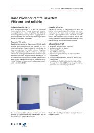
Kaco Powador 02 Series<br />
Great flexibility, simple installation<br />
New current sensor<br />
The new current sensor of the Kaco Powador 02 series<br />
enables more precise control and better MPP tracking.<br />
The inverters with electrical isolation satisfy with their<br />
effortless installation, highest efficiency as well as optimal<br />
operation by means of thin-film modules.<br />
Effortless installation<br />
The connections are situated on their own PCB within<br />
the casing and can be connected easily. For a faster and<br />
easier wiring, all communication connections are<br />
mounted separately on a PCB. ADC circuit breaker is<br />
integrated into the device.<br />
Highest efficiency<br />
With an efficiency of 96 %, theinvertersoftheKaco<br />
Powador 02 series are among the top-rated of their<br />
The integrated transformer of the Powador 02 series ensures<br />
electrical isolation from the mains, which allows the<br />
use of thin-film modules without any problems.<br />
class. Due to the electrical isolation, the devices can be<br />
installed even in places that would be impossible for<br />
devices without transformers. The wide input voltage<br />
range makes the devices extremely flexible.<br />
Advantages in brief<br />
n International inverters for 16 countries<br />
n New current sensor<br />
n Electrical isolation<br />
n Simple installation<br />
n High efficiency<br />
n Simple wiring<br />
n Optimal for thin-film modules<br />
n Display of earthing status of the PV generator<br />
With an efficiency of 96 %, the inverters of the Kaco Powador<br />
02 series are among the top-rated of their class.
...................................................................................................................................................................<br />
Single-phased GRID-CONNECTED INVERTERS<br />
...................................................................................................................................................................<br />
Art. No. 0201124 0201126 0201128 0201130 0201132<br />
Model Kaco Powador 2002 INT Kaco Powador 3002 INT Kaco Powador 4202 INT Kaco Powador 5002 INT Kaco Powador 6002 INT<br />
MPPvoltagerange 125-510V 200-510V 200-510V 200-510V 200-510V<br />
Open circuit voltage * 600 V 600 V 600 V 600 V 600 V<br />
Max. input current 14.3 A13.5 A18.5 A22.4 A26.5 A<br />
Nominal output ** 1650 W 2500 W 3500 W 4200 W 4600 / 5000 W<br />
Output voltage 190 - 264 V 190 - 264 V 190 - 264 V 190 - 264 V 190 - 264 V<br />
Powerfactorcosphi 0.8inductive,<br />
0.8 inductive,<br />
0.8 inductive,<br />
0.8 inductive,<br />
0.8 inductive,<br />
0.8 capacitive<br />
0.8 capacitive<br />
0.8 capacitive<br />
0.8 capacitive<br />
0.8 capacitive<br />
Frequency 50Hz 50Hz 50Hz 50Hz 50Hz<br />
Harmonic distortion < 3 %
40<br />
...................................................................................................................................................................<br />
GRID-CONNECTED INVERTERS Single-phased<br />
...................................................................................................................................................................<br />
Kaco Powador 00 Series<br />
Inverters without transformers<br />
Higher efficiency<br />
Without transformers, the inverters of the Kaco 00<br />
series achieve optimal efficiency. As a specialist for<br />
inverters without transformers, Kaco has equipped all<br />
devices of the 00 series with a full bridge and omitted<br />
the boost converters. The self-controlled devices emulate<br />
the sinus voltage curve of the public power grid<br />
using a H4 bridge. Prerequisite for using the 00 series<br />
inverters is an input voltage higher than the grid peak<br />
voltage.<br />
Simple installation<br />
With a MPP range of 350 to 600 V and an off-load<br />
voltage of 800 V the conditions for a simple system<br />
dimensioning are ideal. The devices are connected to<br />
the grid by screw terminals. The redundant 3-phase<br />
monitoring, including an AC/DC sensitive residual-cur-<br />
The Powador 3200 – 5500 without transformers can be single-phase<br />
connected individually, due to their nominal output.<br />
rent-operated protective device, facilitates the grid<br />
connection, even in the case of systems with several<br />
inverters.<br />
Long service life<br />
All inverters operate up to outputs of 8 kW with silent<br />
and purely passive cooling. The lost heat is optimally<br />
dissipated by the cooling element on the back. This<br />
cooling without mechanical fans reduces error sources<br />
and thus achieves a long life-cycle of the devices.<br />
100 % feed-in<br />
The Kaco Powador 7900 was specifically developed for<br />
applications with connections limits of 20 kW. Due to<br />
the 100 % symmetrical feed-in of 20 kW, not one watt<br />
of power is wasted, not even in Spain, Italy or Greece.<br />
The single-phase Powador 6600 – 9600 have a nominal output<br />
of more than 5 kW; for this reason the unbalanced load<br />
between feed-in phases should be considered during the<br />
dimensioning.
...................................................................................................................................................................<br />
Single-phased GRID-CONNECTED INVERTERS<br />
...................................................................................................................................................................<br />
Art. No. 0201462 0201463 0201464 0201465 0201466<br />
Model Kaco Powador 3200 Kaco Powador 4400 Kaco Powador 5300 Kaco Powador 5500 Kaco Powador 6600<br />
DCS INT<br />
DCS INT<br />
DCS INT<br />
DCS INT<br />
DCS INT<br />
MPPvoltagerange 350-600V 350-600V 350-600V 350-600V 350-600V<br />
Open circuit voltage 800 V 800 V 800 V 800 V 800 V<br />
Max. input current 8.6 A 12.0 A14.5 A15.2 A18.0 A<br />
Nominal output 2600 W 3600 W 4400 W 4600 W 5500 W<br />
Output voltage 190 - 264 V 190 - 264 V 190 - 264 V 190 - 264 V 190 - 264 V<br />
Powerfactorcosphi 0.8inductive,<br />
0.8 inductive,<br />
0.8 inductive,<br />
0.8 inductive,<br />
0.8 inductive,<br />
0.8 capacitive<br />
0.8 capacitive<br />
0.8 capacitive<br />
0.8 capacitive<br />
0.8 capacitive<br />
Frequency 50Hz 50Hz 50Hz 50Hz 50Hz<br />
Harmonic distortion < 3 %
42<br />
...................................................................................................................................................................<br />
GRID-CONNECTED INVERTERS Single-phased<br />
...................................................................................................................................................................<br />
Art. No. 0201467 0201468 0201469 0201470<br />
Model Kaco Powador 7700 DCS INT Kaco Powador 7900 DCS INT Kaco Powador 8600 DCS INT Kaco Powador 9600 DCS INT<br />
MPPvoltagerange 350-600V 350-600V 350-600V 350-600V<br />
Open circuit voltage 800 V 800 V 800 V 800 V<br />
Max. input current 19.0 A19.7 A21.4 A24.0 A<br />
Nominal output 6400 W 6650 W 7200 W 8000 W<br />
Output voltage 190 - 264 V 190 - 264 V 190 - 264 V 190 - 264 V<br />
Power factor cos phi 0.8 inductive, 0.8 capacitive 0.8 inductive, 0.8 capacitive 0.8 inductive, 0.8 capacitive 0.8 inductive, 0.8 capacitive<br />
Frequency 50Hz 50Hz 50Hz 50Hz<br />
Harmonic distortion < 3 %
44<br />
...................................................................................................................................................................<br />
GRID-CONNECTED INVERTERS Single-phased<br />
...................................................................................................................................................................<br />
SMA Sunny Boy<br />
Flexible pioneers<br />
As the first manufacturer of an inverter suitable for<br />
mass production, SMAhas concentrated on repeatedly<br />
diversifying the implementation possibilities with new<br />
technologies, so that today any system constellation<br />
from 400 Wp and upwards can be optimally realized<br />
with an SMAinverter. SMAdevelops and manufactures<br />
the inverters for a life span of more than 20 years and<br />
produces at the company headquarters in Niestetal,<br />
near Kassel, Germany.<br />
The choice is yours: with or without transformer<br />
SMAinverters are available with or without transformers.<br />
While the transformerless concept offers the ability<br />
to use such latest technologies as H5 topology and is<br />
also extremely lightweight, the transformer device is<br />
the first choice for those who want galvanic isolation.<br />
In addition, transformer-based devices offer the best<br />
possibilities for combination with thinfilm modules.<br />
A new generation of electrically isolated inverters: Full of<br />
state-of-the-art SMA technology, the Sunny Boy HF delivers<br />
the highest yields for inverters with transformers of this<br />
performance class.<br />
The new generation: globally communicative<br />
Just radio where previously cables were required –<br />
Bluetooth makes it possible. The Sunny Boys of the<br />
new generation are provided with this innovative<br />
radio technology. Set for international action: the<br />
new Sunny Boy speaks German, English, French, Spanish,<br />
Italian, and Greek.<br />
Easy installation of the new Sunny Boy<br />
In addition to its completely new installation and wiring<br />
concept, the new Sunny Boy is not only 20 percent<br />
lighter, it is also clearly reduced in volume. Installation<br />
in a flash on a top hat rail or wall fixture is thus<br />
guaranteed. The concept is rounded off by wiring without<br />
tools due to special SMAspring-type clamps and<br />
effective anti-theft device.<br />
The new generation of the Sunny Boy series: with Bluetooth<br />
and flexible country settings as standard.
...................................................................................................................................................................<br />
Single-phased GRID-CONNECTED INVERTERS<br />
...................................................................................................................................................................<br />
Art. No. 0201026 0201027 0201028 0201583 0201584<br />
Model SMASB 3000TL-20 SMASB 4000TL-20 SMASB 5000TL-20 SMASB 3000TL-21 SMASB 4000TL-21<br />
MPPvoltagerange 188-440V 175-440V 175-440V 175-500V 175-500V<br />
Open circuit voltage 550 V 550 V 550 V 750 V 750 V<br />
Max.inputcurrent 1x17A2x15A2x15A2x15A2x15A<br />
Nominal output 3000 W 4000 W 4600 W 3200 W 4200 W<br />
Output voltage 180 - 280 V 180 - 280 V 180 - 280 V 180 - 280 V 180 - 280 V<br />
Powerfactorcosphi 1 1 1 1,0.8(leading)-0.81,<br />
0.8 (leading) - 0.8<br />
(lagging)<br />
(lagging)<br />
Frequency 50 Hz ±4.5Hz 50Hz±4.5Hz 50Hz±4.5 Hz 50, 60 Hz ±5 Hz 50, 60 Hz ±5 Hz<br />
Harmonic distortion < 4 %
46<br />
...................................................................................................................................................................<br />
GRID-CONNECTED INVERTERS Single-phased<br />
...................................................................................................................................................................<br />
Sunways AT & NT<br />
Yield-oriented and innovative<br />
Leading-edge technology for all applications<br />
Using state-of-the-art technology with innovative control,<br />
the inverters of the series Sunways AT achieve<br />
constant yields even under difficult weather conditions.<br />
The completely re-engineered units of the NT<br />
series convince with their even improved performance<br />
data and larger scope of functions. In the area of 2500<br />
to 5000 Watt therefore, the single-phase inverters of<br />
the series AT and NT offer leading-edge technology for<br />
all applications.<br />
Sunways AT series<br />
The inverters of the Sunways AT series impress mainly<br />
by their extraordinary flexibility in plants with thinlayer<br />
or silicon modules. The units without transformers<br />
and a range of input voltage of 180 to 600 volts<br />
achieve consistently high and constant efficiency even<br />
with variable DC voltages and varying output ranges.<br />
The HERIC ® topology with control generally excludes<br />
negative voltages.<br />
Simple design and great flexibility speak in favour of the<br />
single-phase Sunways inverters of the AT and NT series.<br />
Sunways NT series<br />
The top efficiency of 97.8 % and the input voltage<br />
range of 340 to 750 volts are only two reasons for the<br />
great flexibility of the Sunways NT series. Another<br />
feature is the position on the inverter, allowing the<br />
easy use of the units across the whole of Europe.<br />
Additional functions<br />
n Integrated DC circuit breaker<br />
n Backlit graphics display and keyboard<br />
n Extensive integrated 128 MB datalogger<br />
n Inverter link via CAN bus<br />
n Ethernet interface for connection to networks<br />
n Interface for direct modem connection<br />
n E-mail alerts in case of system errors<br />
n Isolated transmitting relay for connection of exter-<br />
nal alarm systems<br />
n Integrated web server for display and configuration<br />
The all-inclusive design of the Sunways inverters enables the<br />
easy and safe connection of all components to the inverter.
...................................................................................................................................................................<br />
Single-phased GRID-CONNECTED INVERTERS<br />
...................................................................................................................................................................<br />
Art. No. 0201303 0201304 0201305 0201306 0201307<br />
Model Sunways AT 2700 Sunways AT 3000 Sunways AT 3600 Sunways AT 4500 Sunways AT 5000<br />
MPPvoltagerange 181-600V 203-600V 242-600V 214-600V 236-600V<br />
Max. input voltage 680 V 680 V 680 V 680 V 680 V<br />
Max. input current 15.5 A15.5 A15.5 A22.0 A22.0 A<br />
Nominal output 2700 W 3000 W 3600 W 4500 W 4600 W<br />
Output voltage 230 V +15 %, -20% 230 V +15 %, -20% 230 V +15 %, -20% 230 V +15 %, -20% 230 V +15 %, -20%<br />
Power factor cos phi Approx. 1 Approx. 1 Approx. 1 Approx. 1 Approx. 1<br />
Frequency 47.5-50.2Hz 47.5-50.2Hz 47.5-50.2Hz 47.5-50.2Hz 47.5-50.2Hz<br />
Harmonic distortion < 4 %
48<br />
...................................................................................................................................................................<br />
GRID-CONNECTED INVERTERS Three-phased<br />
...................................................................................................................................................................<br />
Danfoss TripleLynx – The most versatile inverter<br />
on the market<br />
The three-phase Danfoss TripleLynx inverters are available<br />
with outputs of 6, 8, 10, 12.5 and 15 kW and are<br />
suitable for outdoor use, weighing a mere 35 kg. Due<br />
to their ease-of-use, geared to economic applications,<br />
and their wide range of operating specifications, these<br />
inverters are the most versatile on the market.<br />
It's all there – wide range of operating specifications<br />
The inverter has two or three independent string<br />
inputs, an extensive operating field, and a three-phase<br />
output, which makes it incredibly versatile. Thanks to<br />
its wide range of operating specifications, the inverter<br />
can be connected to a variety of modules each with<br />
different string configurations.<br />
High output due to effective MPP trackers<br />
and high efficiency<br />
Three individual MPP controllers always ensure an optimal<br />
output of the system, irrespective of the differences<br />
in size or the location of the PV modules. The<br />
accuracy of the MPP controllers was verified by the<br />
Viennese Arsenal Research Institute, measuring an effi-<br />
The transformerless Danfoss TripleLynx inverter series with<br />
three-phase power supply and a sensational effectiveness of<br />
98 %.<br />
ciency of 99.9 % of the MPP controller. With an effectiveness<br />
of 98 %, this inverter positions itself at the top<br />
of the three-phase devices on the market.<br />
Three-phase grid connection<br />
Aperfectly symmetrical three-phase power supply<br />
requires nothing more than an inverter. Athree-phase<br />
inverterensuresthree-phaseoutputatalltimesaswell<br />
as compliance with the rules for grid connection irrespective<br />
of string fluctuations on the input side.<br />
Features and innovations<br />
n Up to three independent power inputs<br />
n Preprogrammed for 16 countries<br />
n Integrated communication board<br />
n Communication with RS485 and integrated modem<br />
n Alarm display for faults<br />
n Integrated DC switch<br />
n Integrated cable lock<br />
n Integrated insulation monitoring<br />
n Separate connection compartment<br />
n Service tool for ultra-easy maintenance<br />
The TripleLynx inverters are optionally available as the Plus<br />
model (incl. reactive power compensation) and the Pro<br />
model(incl.webserver).
...................................................................................................................................................................<br />
Three-phased GRID-CONNECTED INVERTERS<br />
...................................................................................................................................................................<br />
Art. No. 0201598 0201599 0201512 0201513 0<strong>2012</strong>05<br />
Model Danfoss TLX 6k + Danfoss TLX 6k Pro + Danfoss TLX 8k + Danfoss TLX 8k Pro + Danfoss TLX 10k +<br />
Max. recommended PV system<br />
power<br />
7100 W 7100 W 9500 W 9500 W 11800 W<br />
Max. DC output 6200 W 6200 W 8240 W 8240 W 10300 W<br />
Max. input current 2 x 12 (24) A2 x 12 (24) A2 x 12 (24) A2 x 12 (24) A2 x 12 (24) A<br />
Max. input voltage 1000 V 1000 V 1000 V 1000 V 1000 V<br />
MPPT range 260 - 800 V 260 - 800 V 345 - 800 V 345 - 800 V 430 - 800 V<br />
IndependentMPPTtrackers2pc. 2pc. 2pc. 2pc. 2pc.<br />
Max. output power 6000 W 6000 W 8000 W 8000 W 10000 W<br />
Nominal output power 6000 W 6000 W 8000 W 8000 W 10000 W<br />
Output voltage 3 x 230 V ±20 % 3 x 230 V ±20 % 3 x 230 V ±20 % 3x230V±20 % 3x230V±20 %<br />
Max.outputcurrent 3x9.0A3x9.0A3x12.0A3x12.0A3x15.0A<br />
Start-uppowerlevel 20W 20W 20W 20W 20W<br />
Stand-by power consumption < 5 W < 5 W < 5 W < 5 W < 5 W<br />
Max. efficiency 97.8 % 97.8 % 97.9 % 97.9 % 98.0 %<br />
Euro efficiency 96.5 % 96.5 % 97 % 97 % >97%<br />
Operating temperature -25 to +60 °C -25 to +60 °C -25 to +60 °C -25 to +60 °C -25 to +60 °C<br />
Rel. humidity 0 - 95 % non<br />
0-95% non<br />
0-95% non<br />
0-95% non<br />
0-95% non<br />
condensing<br />
condensing<br />
condensing<br />
condensing<br />
condensing<br />
Protection mode IP54 IP54 IP54 IP54 IP54<br />
Circuit type Transformerless, three- Transformerless, three- Transformerless, three- Transformerless, three- Transformerless, threephasedphasedphasedphasedphased<br />
Powerfactor(P>20%) 0.97 0.97 0.97 0.97 0.97<br />
Harmonic distortion < 4 %
50<br />
...................................................................................................................................................................<br />
GRID-CONNECTED INVERTERS Three-phased<br />
...................................................................................................................................................................<br />
Art. No. 0<strong>2012</strong>11 0<strong>2012</strong>06 0<strong>2012</strong>12 0<strong>2012</strong>07 0<strong>2012</strong>13<br />
Model Danfoss TLX 10k Pro + Danfoss TLX 12.5k + Danfoss TLX 12.5k Pro + Danfoss TLX 15k + Danfoss TLX 15k Pro +<br />
Max. recommended PV system<br />
power<br />
11800 W 14700 W 14700 W 17700 W 17700 W<br />
Max. DC output 10300 W 12900 W 12900 W 15500 W 15500 W<br />
Max. input current 2 x 12 (24) A3 x 12 (36) A3 x 12 (36) A3 x 12 (36) A3 x 12 (36) A<br />
Max. input voltage 1000 V 1000 V 1000 V 1000 V 1000 V<br />
MPPT range 430 - 800 V 430 - 800 V 430 - 800 V 430 - 800 V 430 - 800 V<br />
IndependentMPPTtrackers2pc. 3pc. 3pc. 3pc. 3pc.<br />
Max. output power 10000 W 12500 W 12500 W 15000 W 15000 W<br />
Nominal output power 10000 W 12500 W 12500 W 15000 W 15000 W<br />
Output voltage 3 x 230 V ±20 % 3 x 230 V ±20 % 3 x 230 V ±20 % 3x230V±20 % 3x230V±20 %<br />
Max.outputcurrent 3x15.0A3x19.0A3x19.0A3x22.0A3x22.0A<br />
Start-uppowerlevel 20W 20W 20W 20W 20W<br />
Stand-by power consumption < 5 W < 5 W < 5 W < 5 W < 5 W<br />
Max. efficiency 98.0 % 98.0 % 98.0 % 98.0 % 98.0 %<br />
Euro efficiency > 97 % >97% >97% >97% >97%<br />
Operating temperature -25 to +60 °C -25 to +60 °C -25 to +60 °C -25 to +60 °C -25 to +60 °C<br />
Rel. humidity 0 - 95 % non<br />
0-95% non<br />
0-95% non<br />
0-95% non<br />
0-95% non<br />
condensing<br />
condensing<br />
condensing<br />
condensing<br />
condensing<br />
Protection mode IP54 IP54 IP54 IP54 IP54<br />
Circuit type Transformerless, three- Transformerless, three- Transformerless, three- Transformerless, three- Transformerless, threephasedphasedphasedphasedphased<br />
Powerfactor(P>20%) 0.97 0.97 0.97 0.97 0.97<br />
Harmonic distortion < 5 %
52<br />
...................................................................................................................................................................<br />
GRID-CONNECTED INVERTERS Three-phased<br />
...................................................................................................................................................................<br />
Kaco Powador TL3 and TR3 series<br />
Inverters from 10 to 18 kW<br />
The latest technology<br />
Kaco only uses state-of-the-art technology for the<br />
manufacture of the new grid inverters of the TL3 and<br />
TR3 series. The devices have extremely flexible applications<br />
within a range of 10 to 18 kW and satisfy the<br />
highest quality requirements. Real three-phase devices,<br />
they supply sinusoidal alternating current with a<br />
phase shift of 120°. The inverters meet all requirements<br />
of the new low and mean voltage directive.<br />
10.0 TL3 / 12.0 TL3 / 14.0 TL3 / 18.0 TL3<br />
The transformerless inverters of the TL3 series operate<br />
with two separate MPP trackers and can process solar<br />
energy from up to four strings which can be completely<br />
asymmetrically loaded. The input voltage range is designed<br />
particularly wide with 350 to 800 V. The start<br />
voltage is already at 250 V, peak efficiency is 98 %.<br />
The transformerless inverters of the Powador TL3 series convince<br />
with the highest efficiency of > 98.0 %.<br />
16.0 TR3 / 18.0 TR3<br />
The inverters with transformers of the TR3 series provide<br />
the best solution for systems of up to 18 kW. Three<br />
strings can be connected per DC input, which enables<br />
the connection of up to nine strings. Three separate<br />
MPP trackers achieve the optimal adjustment. The<br />
peak efficiency is 96.2 %.<br />
Other benefits at a glance<br />
n Cooling by temperature-controlled fans<br />
n RS485 interface for communication<br />
n Integrated web server for seamless monitoring via<br />
Ethernet<br />
n USB interface for easy software updates<br />
n Graphic display to show the operating data<br />
n Simple installation due to compact housing<br />
n Asymmetrical dimensioning possible<br />
The TR3 inverter series with transformers is particularly<br />
suited to modules requiring grounding due to their electrical<br />
isolation.
...................................................................................................................................................................<br />
Three-phased GRID-CONNECTED INVERTERS<br />
...................................................................................................................................................................<br />
Art. No. 0<strong>2012</strong>50 0<strong>2012</strong>51 0<strong>2012</strong>52 0201301 0<strong>2012</strong>54 0<strong>2012</strong>55<br />
Model Kaco Powador 10.0 Kaco Powador 12.0 Kaco Powador 14.0 Kaco Powador 18.0 Kaco Powador 16.0 Kaco Powador 18.0<br />
TL3<br />
TL3<br />
TL3<br />
TL3<br />
TR3<br />
TR3<br />
MPP voltage range * 200 - 800 V 200 - 800 V 200 - 800 V 200 - 800 V 200 - 510 V 200 - 510 V<br />
Open circuit voltage ** 1000 V 1000 V 1000 V 1000 V 600 V 600 V<br />
Max.inputcurrent 2x18.6A2x18.6A2x18.6A2x18.6A3x26A 3x26A<br />
Nominal output 9000 W 10000 W 12500 W 15000 W 13500 W 15000 W<br />
Output voltage 400 / 230 V 400 / 230 V 400 / 230 V 400 / 230 V 400 / 230 V 400 / 230 V<br />
Powerfactorcosphi 0.8inductive, 0.8 inductive, 0.8 inductive, 0.8 inductive, 0.8 inductive, 0.8 inductive,<br />
0.8 capacitive 0.8 capacitive 0.8 capacitive 0.8 capacitive 0.8 capacitive 0.8 capacitive<br />
Frequency 50Hz 50Hz 50Hz 50Hz 50Hz 50Hz<br />
Harmonic distortion < 3 %
54<br />
...................................................................................................................................................................<br />
GRID-CONNECTED INVERTERS Three-phased<br />
...................................................................................................................................................................<br />
Kaco Powador central inverters<br />
Efficient and reliable<br />
Individual performance<br />
With generator outputs of 25 to 1000 kW, the central<br />
inverters of the Kaco Powador series cover an enormous<br />
performance range completely. The ability of<br />
combining all devices freely enables any project to be<br />
realised optimally and individually – from single-family<br />
houses to megawatt solar parks.<br />
Powador TL3 series<br />
Based on the concept of the successful 30 kW family<br />
and the switching concept of the Powador 14.0 TL3,<br />
these devices have been redesigned completely: As<br />
three-phase devices they feed in between the phases<br />
with a typical shift of 120°. Anumber of country-specific<br />
presets are programmed into the inverters; simply<br />
select the required ones on site on the devices. To<br />
achieve optimal adjustment the devices operate three<br />
separate MPP trackers, which can be loaded asymmetrically.<br />
The input voltage range is designed particularly<br />
wide with 350 to 800 V.<br />
The transformerless three-phase current inverters of the<br />
Powador TL3 series can be used internationally and are<br />
extremely flexible regarding their design.<br />
Powador XP series<br />
The central inverters of the Powador XP series are<br />
leading with regard to user-friendliness and investment<br />
returns. The latest signal processor technology<br />
provides highest performance, reliability and efficiency.<br />
The completely digital control allows userfriendly<br />
operation and maintenance as well as extensive<br />
monitoring and communication options.<br />
Advantages in brief<br />
n Generatoroutputof25to1000kW<br />
n Ability to combine all devices<br />
n Patented MPP control<br />
n New IGBT circuit breaker<br />
n 3-phase voltage monitoring for devices without<br />
transformers<br />
n Grid monitoring by means of BiSi for devices with<br />
transformers<br />
n In addition to the DC switch, the XL model of the<br />
Powador 30.0 / 37.5 / 39.0 TL3 has integrated string<br />
protection and overvoltage protection<br />
The Kaco Powador Megawatt Station consists of three combined<br />
XP350-HV TL.
...................................................................................................................................................................<br />
Three-phased GRID-CONNECTED INVERTERS<br />
...................................................................................................................................................................<br />
Art. No. 0<strong>2012</strong>41 0<strong>2012</strong>47 0<strong>2012</strong>42 0<strong>2012</strong>48 0<strong>2012</strong>43 0<strong>2012</strong>49<br />
Model Kaco Powador 30.0 Kaco Powador 30.0 Kaco Powador 37.5 Kaco Powador 37.5 Kaco Powador 39.0 Kaco Powador 39.0<br />
TL3 M INT<br />
TL3 XL INT TL3 M INT<br />
TL3 XL INT TL3 M INT<br />
TL3 XL INT<br />
MPPvoltagerange 350-800V 350-800V 350-800V 350-800V 350-800V 350-800V<br />
Open circuit voltage 1000 V 1000 V 1000 V 1000 V 1000 V 1000 V<br />
Max.inputcurrent 3x34A3x34A3x34A3x34A3x34A3x34A<br />
Nominal output 25000 W 25000 W 30000 W 30000 W 33300 W 33300 W<br />
Output voltage 400 / 230 V 400 / 230 V 400 / 230 V 400 / 230 V 400 / 230 V 400 / 230 V<br />
Powerfactorcosphi 0.8inductive, 0.8 inductive, 0.8 inductive, 0.8 inductive, 0.8 inductive, 0.8 inductive,<br />
0.8 capacitive 0.8 capacitive 0.8 capacitive 0.8 capacitive 0.8 capacitive 0.8 capacitive<br />
Frequency 50Hz 50Hz 50Hz 50Hz 50Hz 50Hz<br />
Harmonic distortion < 3 %
56<br />
...................................................................................................................................................................<br />
GRID-CONNECTED INVERTERS Three-phased<br />
...................................................................................................................................................................<br />
Art. No. 0201190 0<strong>2012</strong>30 0<strong>2012</strong>32 0<strong>2012</strong>31<br />
Model Kaco Powador XP100-HV INT Kaco Powador XP200-HV INT Kaco Powador XP200-HV TL<br />
INT<br />
Kaco Powador XP250-HV INT<br />
MPPvoltagerange 450-800V 450-830V 450-830V 450-830V<br />
Open circuit voltage 1000 V 1000 V 1000 V 1000 V<br />
Max. input current 245 A467 A467 A611 A<br />
Nominal output 100000 W 200000 W 200000 W 250000 W<br />
Output voltage 400 V (±10 %) 400 V (±10 %) 3 x 290 V (±10 %) 400 V (±10 %)<br />
Power factor cos phi 0.8 inductive, 0.8 capacitive 0.8 inductive, 0.8 capacitive 0.8 inductive, 0.8 capacitive 0.8 inductive, 0.8 capacitive<br />
Frequency 50/60Hz 50/60Hz 50/60Hz 50/60Hz<br />
Harmonic distortion < 3 %
58<br />
...................................................................................................................................................................<br />
GRID-CONNECTED INVERTERS Three-phased<br />
...................................................................................................................................................................<br />
SMA Sunny Tripower – Three-phase feed for<br />
simple system planning<br />
Greatest efficiency<br />
Cost-effective, safe and flexible – these qualities make<br />
the SMASunny Tripower inverters extremely efficient<br />
inverters. With an efficiency of 98%, open circuit voltage<br />
up to 1000 V and power ratings of 10 to 17 kW, the<br />
inverters are perfectly suited for all applications.<br />
The latest technology<br />
The innovative product qualities of the Sunny Tripower<br />
series guarantee simple installation, high yields and<br />
safe grid support. The multi-string technology and<br />
the large input voltage range make the inverters ready<br />
for all system dimensioning – from 10 kW to the megawatt<br />
range.<br />
Best safety<br />
The Sunny Tripower inverters meet the requirements<br />
of the VDEW Mean Voltage directives and are there-<br />
fore a reliable part of the grid management. The safety<br />
concept with string failure detection, electronic string<br />
protection and integrable lightning protection function<br />
ensures greatest availability and reduces system<br />
costs.<br />
Advantages in brief<br />
n Integrated DC circuit breaker ESS<br />
n String current monitoring<br />
n Flexible module dimensioning with two boost converters<br />
n Tool-free cable connection<br />
n Innovative DC connector system<br />
n Easily accessible connection area<br />
n Communication via Bluetooth<br />
The SMA Sunny Tripower – efficient, innovative and safe. Monitoring of system data with the SMA Sunny Beam.
...................................................................................................................................................................<br />
Three-phased GRID-CONNECTED INVERTERS<br />
...................................................................................................................................................................<br />
Art. No. 0201481 0201111 0201112 0201113 0201114<br />
Model STP 8000TL-10 STP 10000TL-10 STP 12000TL-10 STP 15000TL-10 STP 17000TL-10<br />
MPPvoltagerange 320-800V 320-800V 380-800V 360-800V 400-800V<br />
Open circuit voltage 1000 V 1000 V 1000 V 1000 V 1000 V<br />
Max. input current (Input A/<br />
Input B)<br />
22 A/ 11 A 22 A/ 11 A 22 A/ 11 A 33 A/ 11 A 33 A/ 11 A<br />
MPPtracker 2pc. 2pc. 2pc. 2pc. 2pc.<br />
Nominal output 8000 W 10000 W 12000 W 15000 W 17000 W<br />
Output voltage 230 / 400 V, three- 230 / 400 V, three230/400V,three- 230 / 400 V, three230/400V,threephasedphasedphasedphasedphased Powerfactorcosphi 1 1 1 1 1<br />
Frequency 50 Hz ±5 Hz 50Hz±5 Hz 50Hz±5 Hz 50Hz±5 Hz 50Hz±5 Hz<br />
Harmonic distortion < 4 %
60<br />
...................................................................................................................................................................<br />
GRID-CONNECTED INVERTERS Three-phased<br />
...................................................................................................................................................................<br />
Sunways NT & PT<br />
Attractive all-inclusive design<br />
Maximum efficiency<br />
Due to the complete re-engineering of the Sunways NT<br />
10000, NT 11000 and NT 12000, the units now can<br />
achieve a maximum efficiency of 97.6 %. The 30 and<br />
33 kW inverters of the PT series set new standards for<br />
compact three-phase units with their efficiency of<br />
more than 98.0 % and maximum DC input voltage of<br />
1000 volts.<br />
Sunways NT series<br />
Due to the precise MPP multi-tracking with three separate<br />
DC inputs, the quick MPP control and the patented<br />
HERIC ® control, these three-phase Sunways NT<br />
inverters meet even the highest requirements. The<br />
input voltage range of 340 to 900 volts at three variably<br />
dimensionable inputs and the possibility of setting the<br />
position at the unit make the new NT series even more<br />
flexible and suitable for all situations and locations in<br />
Europe.<br />
Sunways PT series<br />
Due to their maximum efficiency of more than 98.0 %,<br />
the three-phase inverters of the Sunways PT series<br />
The three-phase Sunways NT series stands out due to their<br />
all-inclusive design, since all inverters are equipped with<br />
extensive accessories as standard.<br />
achieve higher-than-average yields and are most efficient.<br />
The Sunways PT series is made even more attractive<br />
by adherence to the new mean voltage directive,<br />
direct support of the EEG (Renewable Energy Law)<br />
feed-in management due to the upgradeable power<br />
control module and the uninterrupted string monitoring<br />
via the "String Box CAN 08" and the Sunways<br />
portal.<br />
Additional functions<br />
n Integrated DC circuit breaker<br />
n Backlit graphics display and keyboard<br />
n Extensive integrated 128 MB datalogger<br />
n Inverter link via CAN bus<br />
n Ethernet interface for connection to networks<br />
n Interface for direct modem connection<br />
n E-mail alerts in case of system errors<br />
n Isolated transmitting relay for connection of exter-<br />
nal alarm systems<br />
n S0 pulse output to control the Sunways display<br />
n Integrated web server for display and configuration<br />
The inverters of the new three-phase Sunways PT series set<br />
new standards, due to their efficiency of 98 % and maximum<br />
input voltage of 1000 V.
...................................................................................................................................................................<br />
Three-phased GRID-CONNECTED INVERTERS<br />
...................................................................................................................................................................<br />
Art. No. 0201312 0201313 0201314 0201316<br />
Model Sunways NT 10000 Sunways NT 11000 Sunways NT 12000 Sunways PT 30k INT<br />
MPPvoltagerange 340-750V 340-750V 340-750V 420-800V<br />
Max. input voltage 900 V 900 V 900 V 1000 V<br />
Max. input current 11.0 Aeach MPP input 11.5 Aeach MPP input 12.8 Aeach MPP input 75.0 A<br />
Nominal output 10000 W 11000 W 12000 W 30000 W<br />
Output voltage 400 V +15 %, -20% 400 V +15 %, -20% 400 V +15 %, -20% 400 V +15 %, -20%<br />
Power factor cos phi 1 or adjustable from ‑0.9 to 1 or adjustable from ‑0.9 to 1 or adjustable from ‑0.9 to 1 or adjustable from ‑0.9 to<br />
+0.9<br />
+0.9<br />
+0.9<br />
+0.9<br />
Frequency 47.5 - 50.2 Hz 47.5 - 50.2 Hz 47.5 - 50.2 Hz 47.5 - 50.2 Hz<br />
Harmonic distortion < 1 %
62<br />
...................................................................................................................................................................<br />
GRID-CONNECTED INVERTERS Accessories<br />
...................................................................................................................................................................<br />
SMA communication products<br />
Sunny Beam – Complete system control<br />
without cables<br />
Convenient and practical, Sunny Beam lets you check<br />
on the status and yield of your solar energy system at a<br />
glance, and at any time. The Sunny Beam can monitor<br />
up to four inverters via wireless interfaces. The performance<br />
of the elegant tabletop device is just as<br />
impressive as its functionality. An integrated solar cell<br />
provides the electricity for truly cable-free operation.<br />
An integrated rechargeable battery ensures operation<br />
also in the absence of solar radiation.<br />
On a large graphic display, you can immediately see the<br />
present output, the daily graph, and the daily values of<br />
the previous 30 days. By pushing and rotating an operating<br />
dial, you can set the individual display settings as<br />
desiredandselectwhichresultsaretobedisplayed.In<br />
addition to its real-time display, Sunny Beam can also<br />
store yield data for the last 30 days. The integrated USB<br />
interface is used to read the saved plant data and to<br />
archive it on the PC by using the Sunny Data Control<br />
software included in the delivery.<br />
Sunny WebBox – The professional datalogger<br />
Plant monitoring, remote diagnosis, data acquisition<br />
and visualisation: The Sunny WebBox is the communi-<br />
The radio-based Sunny Beam from SMA ensures easy and<br />
cost-effective system monitoring.<br />
cation center of your power supply system. On the<br />
system side, it continuously gathers all data from the<br />
inverters and thereby allows you to remain constantly<br />
informedofyoursystem'sstatusatanygiventime.Asa<br />
multifunctional datalogger, it also offers you a wide<br />
range of possibilities for displayinig, archiving, and<br />
further processing the system data.<br />
The WebBox is the right choice for the ambitious system<br />
operator who wishes to document the system data<br />
completely and continuously. Even from remote locations,<br />
where no DSL or telephone connection is available,<br />
the PV system can display its measurement data at<br />
Sunny Portal via the optional GSM modem.<br />
Sunny SensorBox<br />
It was specially developed to further refine performance<br />
analysis of solar power stations. With the Sunny<br />
SensorBox, it is now possible to acquire environmental<br />
data also, such as irradiation and module temperature,<br />
in order to detect any PV module faults or failures<br />
promptly. The Sunny SensorBox is simply connected<br />
with the inverters via the serial RS485 data link to a<br />
Sunny WebBox.<br />
The SMA WebBox ensures professional monitoring of up to<br />
50 inverters on the Internet.
...................................................................................................................................................................<br />
Accessories GRID-CONNECTED INVERTERS<br />
...................................................................................................................................................................<br />
Art. No. 0201048 0201099 0201050 0201051<br />
Model SMASunny Beam incl. USB SMASunny Beam Bluetooth SMASunny WebBox without SMASunny WebBox with<br />
cable<br />
modem<br />
analog modem<br />
Interface USB 1.1 USB 1.1 Ethernet Ethernet, analog modem<br />
Frequency 868 MHz - - -<br />
Approx. range outdoors /<br />
indoors<br />
100 / 30 m 100 m - -<br />
Display LCD, graphic display, 160 x 100 LCD, graphic display, 160 x 100 - -<br />
pixel<br />
pixel<br />
Handling Rotary push-button Rotary push-button - -<br />
Languages English / French / German / English / French / German / - -<br />
Spanish<br />
Spanish / Italian / Portuguese /<br />
Dutch / Czech<br />
Data communication Radio Bluetooth With RS485 up to 50 inverters With RS485 up to 50 inverters<br />
Memory expansion SD card - - 1 GB 1 GB<br />
Solar irradiation measuring - - - -<br />
Module temperature sensor - - - -<br />
Power supply - - Power supply unit, 115 - 230 V Power supply unit, 115 - 230 V<br />
Frequency range of power<br />
supply unit<br />
- - 50-60Hz 50-60Hz<br />
Power consumption (nominal /<br />
max.)<br />
-/- -/- 4W/12W 4W/12W<br />
Ambient temperature - - -20 to +55 °C -20 to +55 °C<br />
Rel. humidity - - 5 - 95 % 5-95%<br />
Protection mode IP20 IP20 - -<br />
Dimensions (W / H / D) 127 mm / 75 mm / 195 mm 127 mm / 75 mm / 195 mm 225 mm / 130 mm / 57 mm 225 mm / 130 mm / 57 mm<br />
Weight 350 g 350 g 750 g 750 g<br />
Warranty 2 years 2 years 2 years 2 years<br />
Norms CE mark CE mark CE mark CE mark<br />
Art. No. 0201052 0201100 0201053<br />
Model SMASunny WebBox with GSM modem SMASunny WebBox Bluetooth SMASunny Sensor Box with mounting<br />
plate<br />
Interface Ethernet, GSM modem Ethernet RS485 to Sunny WebBox<br />
Frequency - - -<br />
Approx. range outdoors /<br />
indoors<br />
- - -<br />
Display - - -<br />
Handling - - -<br />
Languages - - -<br />
Data communication With RS485 up to 50 inverters With Bluetooth up to 50 inverters -<br />
Memory expansion SD card 1 GB 1 GB -<br />
Solar irradiation measuring - - ASI solar module, precision ±8 %<br />
Module temperature sensor - - Pt100, precision ±0.5 °C<br />
Power supply Power supply unit, 115 - 230 V Power supply unit, 115 - 230 V Via RS485 line from Sunny WebBox<br />
Frequency range of power<br />
supply unit<br />
50-60Hz 50-60Hz 50-60Hz<br />
Power consumption (nominal /<br />
max.)<br />
4W/12W 4W/12W -/-<br />
Ambient temperature -20 to +55 °C -20 to +55 °C -25 to +70 °C<br />
Rel. humidity 5 - 95 % 5-95% -<br />
Protection mode - - IP65<br />
Dimensions (W / H / D) 225 mm / 130 mm / 57 mm 225 mm / 130 mm / 57 mm 120 mm / 90 mm / 50 mm<br />
Weight 750 g 750 g 500 g<br />
Warranty 2 years 2 years 2 years<br />
Norms CE mark CE mark CE mark<br />
Accessories<br />
Art. No. 0201049 0201060 0201061 0201091 0201087<br />
Model SMAPiggy Back SMAPiggy Back RS485 SMAPiggy Back RS485 SMAPiggy Back RS485 SMAearthing set<br />
wireless<br />
interface SB<br />
interface NG<br />
interface SMC<br />
positive ESHV-P-NR<br />
Function Radio transmission from Data transmission by Data transmission by Data transmission by Compatible to Sunny<br />
Sunny Boy to Sunny cable RS485 from Sunny cable RS485 from Sunny cable RS485 from Sunny Boy and SMC with<br />
Beam<br />
Boy to WebBox Boy New Generation to<br />
WebBox<br />
Mini Central to WebBox transformer<br />
Inverter communication in a<br />
network<br />
Up to 4 inverters Up to 50 inverters Up to 50 inverters Up to 50 inverters -<br />
Connection to SMA inverter Add-on kit A Add-on kit A Add-on kit A Add-on kit A -<br />
Warranty 2 years 2 years 2 years 2 years 2 years<br />
Continued on next page<br />
TRITEC Group www.tritec-energy.com | © <strong>2012</strong>1214-1 | The content of this datasheet is subject to change without prior notice<br />
63
64<br />
...................................................................................................................................................................<br />
GRID-CONNECTED INVERTERS Accessories<br />
...................................................................................................................................................................<br />
Art. No. 0201088 0201089 0201090 0201093 0201094<br />
Model SMAearthing set<br />
negative ESHV-N-NR<br />
SMAPower Balancer<br />
cable PBL-YCABLE-10<br />
SMAPower Balancer<br />
add-on kit PBL-SMC-10-<br />
NR<br />
SMAfuse kit 8 A(SIBA,<br />
900 V)<br />
SMAfuse kit 10 A(SIBA,<br />
900 V)<br />
Function Compatible to Sunny Pluggable to<br />
Add-on kit to connector String fuse kit for String fuse kit for<br />
Boy and SMC with SMC 9000/10000/11000- system, to<br />
SMC 9000/10000/11000- SMC 9000/10000/11000transformer<br />
TL-10<br />
SMC 6000/7000/8000TL TL<br />
TL<br />
Inverter communication in a<br />
network<br />
- - - - -<br />
Connection to SMAinverter - - - - -<br />
Warranty 2 years 2 years 2 years 2 years 2 years<br />
Art. No. 0201095 0201096 0201097 0201098 0201101<br />
Model SMAfuse kit 12 A(SIBA, SMAfuse kit 16 A(SIBA, SMAfuse kit 20 A(SIBA, SMAwind sensor incl. SMAPiggy Back<br />
900 V)<br />
900 V)<br />
900 V)<br />
3mcable<br />
Bluetooth<br />
Function String fuse kit for String fuse kit for String fuse kit for For the connection to Transmission Bluetooth<br />
SMC 9000/10000/11000- SMC 9000/10000/11000- SMC 9000/10000/11000- SMASensorBox from Sunny Boy and<br />
TL<br />
TL<br />
TL<br />
SMC to Sunny Beam<br />
Inverter communication in a<br />
network<br />
- - - - -<br />
Connection to SMAinverter - - - - -<br />
Warranty 2 years 2 years 2 years 2 years 2 years<br />
TRITEC Group www.tritec-energy.com | © <strong>2012</strong>1214-1 | The content of this datasheet is subject to change without prior notice
Control and Measuring<br />
Instruments<br />
We produce our own monitoring and measuring<br />
instruments and are development leaders in this area.<br />
With a simple push of a button you can measure the<br />
current-voltage curve using the mobile characteristics<br />
analyser TRI-KA. Additionally, we offer our own heat<br />
sensors, which can measure the outside as well as the<br />
module temperature, in order to improve the measuring<br />
results of dataloggers.<br />
TRITEC<br />
SOLAR-LOG<br />
SOLARFOX<br />
67
68<br />
...................................................................................................................................................................<br />
CONTROL AND MEASURING INSTRUMENTS Characteristics Analyser<br />
...................................................................................................................................................................<br />
TRI-KA – The mobile characteristics analyser: Now<br />
even more efficient<br />
Mobile portable measuring instrument<br />
The new TRI‑KAnot only identifies the current voltage<br />
curves of module strings, but also of individual photovoltaic<br />
modules. The I-U characteristic curve, output,<br />
short-circuit current and open-circuit voltage are<br />
recorded by a 16 bit processor. During each measurement<br />
the TRI‑KAadjusts the measuring range and<br />
sample rate optimally. The device is easily and intuitively<br />
operated using the menus on the colour touch<br />
screen. The characteristic curve measured by the<br />
TRI‑KAcan be converted to a STC characteristic curve<br />
based on the values measured by the sensor TRI‑SEN<br />
and displayed. In addition, the STC ideal characteristic<br />
curve of the manufacturer can be displayed, due to the<br />
integrated module data base.<br />
Wireless sensor<br />
Without contact, the wireless sensor TRI‑SEN measures<br />
the cell temperature, the angle of inclination and the<br />
irradiation at the solar module level. The measured<br />
values are wirelessly transferred directly to the main<br />
instrument, the TRI‑KA. The reference cell for the<br />
The TRI‑KA characteristics analyser and the TRI‑SEN irradiation<br />
and temperature sensor are easy to operate and provide<br />
reliable measurements.<br />
measuring of the irradiation can be either a monocrystalline<br />
or a polycrystalline cell.<br />
Evaluation software<br />
The evaluation software was also completely overhauled.<br />
The TRI‑KAsoftware can evaluate, manage<br />
and store the measured module data on the PC. With<br />
a few steps of the guided Wizard, the measured data is<br />
saved to the respective customer or system directory.<br />
Further measurements of the same system can then be<br />
added, sorted by date, and compared with the software.<br />
Advantages in brief<br />
n Mobile portable measuring instrument<br />
n Wireless sensor<br />
n Simple menu navigation on colour touch screen<br />
n Large measuring range: 1.0 – 1000 V and 0.1 – 15.0 A<br />
n Creation of system and maintenance protocols<br />
n Output comparison for several years<br />
n Simple identification of errors and faults of PV sys-<br />
tems and PV modules<br />
With the evaluation software the individual strings are evaluated<br />
and combined to individual installations. Measurement<br />
reports from single strings, single modules and from<br />
the entire systems can be printed.
...................................................................................................................................................................<br />
Characteristics Analyser CONTROL AND MEASURING INSTRUMENTS<br />
...................................................................................................................................................................<br />
Art. No. 0802201<br />
Model TRI-KAcomplete set<br />
Included in delivery 1 TRI‑KA, 1 TRI‑SEN, 1 rugged case with rubber foam padding, TRI‑KAmeasurement cable sets (MC3, MC4, Huber+Suhner, Tyco,<br />
SunClix and without connectors), 1 TRI‑SEN mounting, 1 SD card (PC user software with user guide), 1 USB SD/SDHC card reader,<br />
2 power supply units (chargeable), operating instructions<br />
Specifications<br />
Model TRI-KATRI-SEN<br />
Measuring I/U characteristic curve, short-circuit current, open-circuit<br />
voltage, MPP current, MPP voltage<br />
Global irradiation, module temperature, angle of inclination<br />
Calculated values STC values (short-circuit current, open-circuit voltage, MPP<br />
current, MPP voltage), fill factor, MPP output, ideal<br />
characteristic curve of module manufacturer<br />
-<br />
Voltage measuring range 1.0 - 1000 V (< ±1 %) (Uoc>5V) -<br />
Current measuring range 0.1 - 15.0 A(< ±1 %) -<br />
Temperature measuring range - 0 - 100 °C (±3 % in relation to a black body)<br />
Irradiation measuring range - 100 - 1200 W/m² (±5 %)<br />
Measuring connection Measuring cable Non-contact measurement<br />
Characteristic curve measuring<br />
duration<br />
15 - 30 seconds -<br />
Save slots for measured curves Depending on size of SD memory card (> 1000 measured<br />
curves with 1 GB)<br />
-<br />
Reference cells - 1 x monocrystalline cell, 1 x polycrystalline cell<br />
Display 3.2 inch colour LCD touch screen (240 x 320 pixels, RGB) B/W LC display (2-line, 16 characters)<br />
Power supply Lithium polymer accumulator, run-time app. 8 hours Lithium polymer accumulator, run-time app. 8 hours<br />
Auto power-off Adjustable (1 - 15 minutes) -<br />
Interface 2 measuring cables to PV string, wireless connection to<br />
TRI‑SEN, SD/SDHC memory card for PC<br />
Wireless connection to TRI‑KA<br />
Ambient temperature 0 to +50 °C 0 to +60 °C<br />
Protection mode IP20 IP20<br />
Insulation Protection class II -<br />
Measuring category CAT II 1000 V, CAT III 600 V -<br />
Dimensions (L / W / H) 210 mm / 105 mm / 41 mm 160 mm / 82 mm / 41 mm<br />
Weight 500 g 200 g<br />
Warranty 2 years 2 years<br />
Norms EN 61010-1, EN 61010-31, CE mark CE mark<br />
Spare parts<br />
Art. No. Model Belongs to Art. No.<br />
0801101 TRI-KAmeasurement cable replacement set for MC3 0802201<br />
0801102 TRI-KAmeasurement cable replacement set for MC4 0802201<br />
0801103 TRI-KAmeasurement cable replacement set for Huber+Suhner 0802201<br />
0801104 TRI-KAmeasurement cable replacement set for Tyco 0802201<br />
0801110 TRI-KAmeasurement cable replacement set without connector 0802201<br />
0802202 TRI-SEN mounting 0802201<br />
0802203 TRI-KAmeasurement cable replacement set for SunClix 0802201<br />
0802205 TRI-KASD/SDHC card reader 0802201<br />
0802206 TRI-KASD/SDHC memory card 0802201<br />
0802208 TRI-KArugged case, empty 0802201<br />
0802209 TRI-KAchargeable power supply unit 0802201<br />
For measurements of (certain) thin-layer modules and special module technologies, please consult TRITEC.<br />
System requirements user software: Microsoft® Windows XP / Vista / 7; Pentium processor with a minimum of 600 MHz or similar; minimum of 256 MB<br />
memory or more; VGAgraphics card with at least 16 bit colour depth (High Color) and a resolution of 1024 x 768 pixels; free hard disc memory of at least<br />
500 MB; keyboard; mouse; USB interface<br />
TRITEC Group www.tritec-energy.com | © <strong>2012</strong>1214-1 | The content of this datasheet is subject to change without prior notice<br />
69
70<br />
...................................................................................................................................................................<br />
CONTROL AND MEASURING INSTRUMENTS Datalogger<br />
...................................................................................................................................................................<br />
The Solar-Log series – The monitoring system for<br />
all photovoltaic systems<br />
State-of-the-art technology<br />
The devices of the Solar-Log series provide simple monitoring<br />
of solar systems of all types. Due to state-ofthe-art<br />
technology, the operation, analysis and display<br />
of all parameters are handled by the web browser. And<br />
the web browser is independent of the operating system.<br />
Great flexibility<br />
The RS485 interface allows the connection and analysis<br />
of all current inverters. The Solar-Log series is a manufacturer-independent<br />
complete solution, which provides<br />
all tools for the professional monitoring and<br />
analysis of solar systems.<br />
Features<br />
n String monitoring<br />
n Monitoring of failure and performance of individual<br />
inverters<br />
The new Solar-Log 500 and Solar-Log 1000 are multilingual and<br />
can be connected to almost any inverter during installation.<br />
n Status and fault monitoring<br />
n Completely internet-enabled; sends messages via email<br />
and SMS<br />
n Existing broadband router can also be used<br />
n S0 output for large displays<br />
n S0 input for electric meter<br />
Additional features of the Solar-Log 1000<br />
n Graphic display with touch screen for direct operation<br />
n Datalogger with 2 x RS485 for mixed operation of<br />
inverters<br />
n USB port for simple data transfer<br />
n Connection of Solar-Log SensorBox or Sensor basic<br />
for the recording of environmental data<br />
n Theft protection via detection loop<br />
The Solar-Log TM portal offers the perfect display of all data<br />
of aphotovoltaic system.
...................................................................................................................................................................<br />
Datalogger CONTROL AND MEASURING INSTRUMENTS<br />
...................................................................................................................................................................<br />
Art. No. 0802195 0802196 0802234 0802235 0802248<br />
Model Solar-Log 200 - for<br />
1inverter<br />
Solar-Log 200BT - for<br />
1 inverter, SMA<br />
Bluetooth<br />
Solar-Log 200WiFi - for<br />
1inverter<br />
Solar-Log 200WiFi BT -<br />
for 1 inverter, SMA<br />
Bluetooth<br />
Solar-Log 200PM+ - for<br />
1inverter,Power<br />
Management<br />
Max.numberofinverters1pc. 1pc. 1pc. 1pc. 1pc.<br />
Software configuration Flexible Flexible Flexible Flexible Flexible<br />
Recommended max. system<br />
size<br />
15 kW 15 kW 15 kW 15 kW 15 kW<br />
Max. cable length 1000 m 1000 m 1000 m 1000 m 1000 m<br />
Voltage(Supply/Device) 230V/12V 230V/12V 230V/12V 220V/12V 230V/12V<br />
Powerconsumption 3W 3W 3W 3W 3W<br />
Ambient temperature -10 to +50 °C -10 to +50 °C -10 to +50 °C -10 to +50 °C -10 to +50 °C<br />
Protection mode IP20 IP20 IP20 IP20 IP20<br />
Casing Plastic Plastic Plastic Plastic Plastic<br />
Display - - - - -<br />
Interface Ethernet - RJ45 bush - Ethernet - RJ45 bush - Ethernet - RJ45 bush - Ethernet - RJ45 bush - Ethernet - RJ45 bush -<br />
10/100 MBit,<br />
10/100 MBit,<br />
10/100 MBit,<br />
10/100 MBit,<br />
10/100 MBit,<br />
1 x RS485/RS422, max. 1 x RS485/RS422, max. 1 x RS485/RS422, max. 1 x RS485/RS422, max. 1 x RS485/RS422, max.<br />
24 V DC, max.<br />
24 V DC, max.<br />
24 V DC, max.<br />
24 V DC, max.<br />
24 V DC, max.<br />
5 Acontinuous current 5 Acontinuous current, 5 Acontinuous current, 5 Acontinuous current, 5 Acontinuous current,<br />
Bluetooth<br />
WiFi<br />
Bluetooth, WiFi input for ripple control<br />
signal, compatibility of<br />
power management<br />
with inverter types on<br />
request<br />
Handling Via web browser Via web browser Via web browser Via web browser Via web browser<br />
Languages Multi-lingual Multi-lingual Multi-lingual Multi-lingual Multi-lingual<br />
Data interpretation Integrated web server Integrated web server Integrated web server Integrated web server Integrated web server<br />
Dimensions (L / W / H) 225 mm / 285 mm / 225 mm / 285 mm / 225 mm / 285 mm / 225 mm / 285 mm / 225mm/285mm/<br />
40 mm<br />
40 mm<br />
40 mm<br />
40 mm<br />
40 mm<br />
Weight 0.80 kg 0.80 kg 0.80 kg 0.80 kg 0.80 kg<br />
Warranty 5 years 5 years 5 years 5 years 5 years<br />
Art. No. 0802249 0802257 0802186 0802187 0802236<br />
Model Solar-Log 200PM+ WiFi Solar-Log 200 - for Solar-Log 500 - for up to Solar-Log 500BT - for up Solar-Log 500WiFi - for<br />
- for 1 inverter, Power 1 inverter, GPRS 10 inverters<br />
to 10 inverters, SMA up to 10 inverters<br />
Management<br />
Bluetooth<br />
Max. number of inverters 1 pc. 1 pc. 10 pc. 10 pc. 10 pc.<br />
Software configuration Flexible Flexible Flexible Flexible Flexible<br />
Recommended max. system<br />
size<br />
15 kW 15 kW 100 kW 100 kW 50 kW<br />
Max. cable length 1000 m 1000 m 1000 m - 1000 m<br />
Voltage(Supply/Device) 230V/12V 230V/12V 230V/12V 230V/12V 220V/12V<br />
Powerconsumption 3W 3W 3W 3W 3W<br />
Ambient temperature -10 to +50 °C -10 to +50 °C -10 to +50 °C -10 to +50 °C -10 to +50 °C<br />
Protection mode IP20 IP20 IP20 IP20 IP20<br />
Casing Plastic Plastic Plastic Plastic Plastic<br />
Display - - Two-line text display Two-line text display Two-line text display<br />
with status LEDs with status LEDs with status LEDs<br />
Interface Ethernet - RJ45 bush - Ethernet - RJ45 bush - Ethernet - RJ45 bush - Ethernet - RJ45 bush - Ethernet - RJ45 bush -<br />
10/100 MBit,<br />
10/100 MBit,<br />
10/100 MBit,<br />
10/100 MBit,<br />
10/100 MBit,<br />
1 x RS485/RS422, max. 1 x RS485/RS422, max. 1 x RS485/RS422, max. 1 x RS485/RS422, max. 1 x RS485/RS422, max.<br />
24 V DC, max.<br />
24 V DC, max.<br />
24 V DC, max.<br />
24 V DC, max.<br />
24 V DC, max.<br />
5 Acontinuous current, 5 Acontinuous current, 5 Acontinuous current, 5 Acontinuous current, 5 Acontinuous current,<br />
input for ripple control GPRS<br />
S0 pulse input/output S0 pulse input/output S0 pulse input/output<br />
signal, WiFi,<br />
(acc. to DIN 43864 & (acc. to DIN 43864 & (acc. to DIN 43864 &<br />
compatibility of power<br />
management with<br />
inverter types on<br />
request<br />
62056)<br />
62056), Bluetooth 62056), WiFi<br />
Handling Via web browser Via web browser Via web browser and Via web browser and Via web browser and<br />
membrane keyboard membrane keyboard membrane keyboard<br />
Languages Multi-lingual Multi-lingual Multi-lingual Multi-lingual Multi-lingual<br />
Data interpretation Integrated web server Integrated web server Integrated web server Integrated web server Integrated web server<br />
Dimensions (L / W / H) 225 mm / 285 mm / 225 mm / 285 mm / 225 mm / 285 mm / 225 mm / 285 mm / 225mm/285mm/<br />
40 mm<br />
40 mm<br />
40 mm<br />
40 mm<br />
40 mm<br />
Weight 0.80 kg 0.80 kg 0.80 kg 0.80 kg 0.80 kg<br />
Warranty 5 years 5 years 5 years 5 years 5 years<br />
Continued on next page<br />
TRITEC Group www.tritec-energy.com | © <strong>2012</strong>1214-1 | The content of this datasheet is subject to change without prior notice<br />
71
72<br />
...................................................................................................................................................................<br />
CONTROL AND MEASURING INSTRUMENTS Datalogger<br />
...................................................................................................................................................................<br />
Art. No. 0802250 0802251 0802188 0802189 0802193<br />
Model Solar-Log 500PM+ - for Solar-Log 500PM+ WiFi Solar-Log 1000 - for up Solar-Log 1000BT - for Solar-Log 1000PM - for<br />
up to 10 inverters, - for up to 10 inverters, to 100 inverters up to 100 inverters, up to 100 inverters,<br />
Power Management Power Management<br />
SMABluetooth Power Management<br />
Max. number of inverters 10 pc. 10 pc. 100 pc. 100 pc. 100 pc.<br />
Software configuration Flexible Flexible Flexible Flexible Flexible<br />
Recommended max. system<br />
size<br />
100 kW 100 kW 1000 kW 1000 kW 1000 kW<br />
Max. cable length 1000 m 1000 m 1000 m - 1000 m<br />
Voltage(Supply/Device) 230V/12V 230V/12V 230V/12V 230V/12V 230V/12V<br />
Powerconsumption 3W 3W 3W 3W 3W<br />
Ambient temperature -10 to +50 °C -10 to +50 °C -10 to +50 °C -10 to +50 °C -10 to +50 °C<br />
Protection mode IP20 IP20 IP20 IP20 IP20<br />
Casing Plastic Plastic Plastic Plastic Plastic<br />
Display Two-line text display Two-line text display Graphic display with Graphic display with Graphic display with<br />
with status LEDs with status LEDs touch screen<br />
touch screen<br />
touch screen<br />
Interface Ethernet - RJ45 bush - Ethernet - RJ45 bush - Ethernet - RJ45 bush - Ethernet - RJ45 bush - Ethernet - RJ45 bush -<br />
10/100 MBit,<br />
10/100 MBit,<br />
10/100 MBit,<br />
10/100 MBit,<br />
10/100 MBit,<br />
1 x RS485/RS422, max. 1 x RS485/RS422, max. 1 x RS485/RS422 and 1 x RS485/RS422 and 1 x RS485/RS422 and<br />
24 V DC, max.<br />
24 V DC, max.<br />
1 x RS485, max. 24 V DC, 1 x RS485, max. 24 V DC, 1 x RS485, max. 24 V DC,<br />
5 Acontinuous current, 5 Acontinuous current, max. 5 Acontinuous max. 5 Acontinuous max. 5 Acontinuous<br />
S0 pulse input/output S0 pulse input/output current, S0 pulse current, S0 pulse current, S0 pulse<br />
(acc. to DIN 43864 & (acc. to DIN 43864 & input/output (acc. to input/output (acc. to input/output (acc. to<br />
62056), input for ripple 62056), input for ripple DIN 43864 & 62056), DIN 43864 & 62056), DIN 43864 & 62056),<br />
control signal,<br />
control signal, WiFi, alarm contact, USB port alarm contact, USB port alarm contact, USB port<br />
compatibility of power compatibility of power (Host), RS232 for (Host), RS232 for (Host), RS232 for<br />
management with management with modems<br />
modems, Bluetooth modems, input for<br />
inverter types on inverter types on<br />
ripple control signal,<br />
request<br />
request<br />
compatibility of power<br />
management with<br />
inverter types on<br />
request<br />
Handling Via web browser and Via web browser and Via web browser and Via web browser and Via web browser and<br />
membrane keyboard membrane keyboard touch screen display touch screen display touch screen display<br />
Languages Multi-lingual Multi-lingual Multi-lingual Multi-lingual Multi-lingual<br />
Data interpretation Integrated web server Integrated web server Integrated web server Integrated web server Integrated web server<br />
Dimensions (L / W / H) 225 mm / 285 mm / 225 mm / 285 mm / 225 mm / 285 mm / 225 mm / 285 mm / 225mm/285mm/<br />
40 mm<br />
40 mm<br />
40 mm<br />
40 mm<br />
40 mm<br />
Weight 0.80 kg 0.80 kg 0.80 kg 0.80 kg 0.80 kg<br />
Warranty 5 years 5 years 5 years 5 years 5 years<br />
Continued on next page<br />
TRITEC Group www.tritec-energy.com | © <strong>2012</strong>1214-1 | The content of this datasheet is subject to change without prior notice
...................................................................................................................................................................<br />
Datalogger CONTROL AND MEASURING INSTRUMENTS<br />
...................................................................................................................................................................<br />
Art. No. 0802238 0802239 0802240 0802241<br />
Model Solar-Log 1000WiFi - for up to Solar-Log 1000WiFi BT - for up Solar-Log 1000GPRS - for up to Solar-Log 1000PM GPRS - for<br />
100 inverters<br />
to 100 inverters, SMA 100 inverters<br />
up to 100 inverters, Power<br />
Bluetooth<br />
Management<br />
Max. number of inverters 100 pc. 100 pc. 100 pc. 100 pc.<br />
Software configuration Flexible Flexible Flexible Flexible<br />
Recommended max. system<br />
size<br />
1000 kW 1000 kW 1000 kW 1000 kW<br />
Max. cable length 1000 m 1000 m 1000 m 1000 m<br />
Voltage(Supply/Device) 220V/12V 230V/12V 230V/12V 230V/12V<br />
Powerconsumption 3W 3W 3W 3W<br />
Ambient temperature -10 to +50 °C -10 to +50 °C -10 to +50 °C -10 to +50 °C<br />
Protection mode IP20 IP20 IP20 IP20<br />
Casing Plastic Plastic Plastic Plastic<br />
Display Graphic display with touch Graphic display with touch Graphic display with touch Graphic display with touch<br />
screen<br />
screen<br />
screen<br />
screen<br />
Interface Ethernet - RJ45 bush - Ethernet - RJ45 bush - Ethernet - RJ45 bush - Ethernet - RJ45 bush -<br />
10/100 MBit, 1 x RS485/RS422 10/100 MBit, 1 x RS485/RS422 10/100 MBit, 1 x RS485/RS422 10/100 MBit, 1 x RS485/RS422<br />
and 1 x RS485, max. 24 V DC, and 1 x RS485, max. 24 V DC, and 1 x RS485, max. 24 V DC, and 1 x RS485, max. 24 V DC,<br />
max. 5 Acontinuous current, max. 5 Acontinuous current, max. 5 Acontinuous current, max. 5 Acontinuous current,<br />
S0 pulse input/output (acc. to S0 pulse input/output (acc. to S0 pulse input/output (acc. to S0 pulse input/output (acc. to<br />
DIN 43864 & 62056), alarm DIN 43864 & 62056), alarm DIN 43864 & 62056), alarm DIN 43864 & 62056), alarm<br />
contact, USB port (Host), contact, USB port (Host), contact, USB port (Host), contact, USB port (Host),<br />
RS232 for modems, WiFi RS232 for modems, Bluetooth, RS232 for modems, GPRS RS232 for modems, input for<br />
WiFi<br />
ripple control signal, GPRS,<br />
compatibility of power<br />
management with inverter<br />
types on request<br />
Handling Via web browser and touch Via web browser and touch Via web browser and touch Via web browser and touch<br />
screen display<br />
screen display<br />
screen display<br />
screen display<br />
Languages Multi-lingual Multi-lingual Multi-lingual Multi-lingual<br />
Data interpretation Integrated web server Integrated web server Integrated web server Integrated web server<br />
Dimensions (L / W / H) 225 mm / 285 mm / 40 mm 225 mm / 285 mm / 40 mm 225 mm / 285 mm / 40 mm 225 mm / 285 mm / 40 mm<br />
Weight 0.80 kg 0.80 kg 0.80 kg 0.80 kg<br />
Warranty 5 years 5 years 5 years 5 years<br />
Continued on next page<br />
TRITEC Group www.tritec-energy.com | © <strong>2012</strong>1214-1 | The content of this datasheet is subject to change without prior notice<br />
73
74<br />
...................................................................................................................................................................<br />
CONTROL AND MEASURING INSTRUMENTS Datalogger<br />
...................................................................................................................................................................<br />
Accessories<br />
Art. No. Model Description Belongs to Art. No.<br />
0802174 Solar-Log cable set to SMA, 3 m Accessory RS485 cable 0802186, 0802187, 0802188, 0802189,<br />
0802193, 0802195, 0802196, 0802234,<br />
0802235, 0802236, 0802238, 0802239,<br />
0802240, 0802241, 0802248, 0802249,<br />
0802257, 0802250, 0802251<br />
0802176 Solar-Log cable set to Danfoss, 3 m Accessory RS485 cable 0802186, 0802187, 0802188, 0802189,<br />
0802193, 0802195, 0802196, 0802234,<br />
0802235, 0802236, 0802238, 0802239,<br />
0802240, 0802241, 0802248, 0802249,<br />
0802257, 0802250, 0802251<br />
0802179 Solar-Log 1000 modem pack (home) Accessory remote maintenance 0802188, 0802189, 0802193<br />
0802180 Solar-Log 1000 modem pack (industry) Accessory remote maintenance 0802188, 0802189, 0802193<br />
0802181 Solar-Log 1000 mobile communications<br />
pack<br />
Accessory remote maintenance 0802188, 0802189, 0802193<br />
0802182 Solar-Log 1000 DIN rail for mobile<br />
communications pack<br />
Accessory remote maintenance 0802188, 0802189, 0802193<br />
0802190 Solar-Log SensorBox suitable for<br />
200/500/1000<br />
0802191 Solar-Log wind sensor, accessory for<br />
SensorBox<br />
0802192 Solar-Log temperature sensor, accessory<br />
for SensorBox<br />
Measuring irradiation and module<br />
temperature<br />
0802186, 0802187, 0802188, 0802189,<br />
0802193, 0802195, 0802196, 0802234,<br />
0802235, 0802236, 0802238, 0802239,<br />
0802240, 0802241, 0802248, 0802249,<br />
0802257, 0802250, 0802251<br />
Measuring wind speed 0802186, 0802187, 0802188, 0802189,<br />
0802193, 0802195, 0802196, 0802234,<br />
0802235, 0802236, 0802238, 0802239,<br />
0802240, 0802241, 0802248, 0802249,<br />
0802257, 0802250, 0802251<br />
Measuring ambient temperature 0802186, 0802187, 0802188, 0802189,<br />
0802193, 0802195, 0802196, 0802234,<br />
0802235, 0802236, 0802238, 0802239,<br />
0802240, 0802241, 0802248, 0802249,<br />
0802257, 0802250, 0802251<br />
0802197 Solar-Log cable set to Kaco, 3 m Accessory RS485 cable 0802186, 0802187, 0802188, 0802189,<br />
0802193, 0802195, 0802196, 0802234,<br />
0802235, 0802236, 0802238, 0802239,<br />
0802240, 0802241, 0802248, 0802249,<br />
0802257, 0802250, 0802251<br />
0802215 Solar-Log RS485 radio package, min. 80 m<br />
range<br />
Radio connection inverter to Solar-Log 0802186, 0802187, 0802188, 0802189,<br />
0802193, 0802195, 0802196, 0802234,<br />
0802235, 0802236, 0802238, 0802239,<br />
0802240, 0802241, 0802248, 0802249,<br />
0802257, 0802250, 0802251<br />
0802216 Solar-Log Powerline package, two-piece Powerline connection Solar-Log to PC 0802186, 0802187, 0802188, 0802189,<br />
0802193, 0802195, 0802196, 0802234,<br />
0802235, 0802236, 0802238, 0802239,<br />
0802240, 0802241, 0802248, 0802249,<br />
0802257, 0802250, 0802251<br />
0802217 Solar-Log Powerline package single, onepiece<br />
Powerline connection Solar-Log to PC 0802186, 0802187, 0802188, 0802189,<br />
0802193, 0802195, 0802196, 0802234,<br />
0802235, 0802236, 0802238, 0802239,<br />
0802240, 0802241, 0802248, 0802249,<br />
0802257, 0802250, 0802251<br />
0802221 Solar-Log cable set to Fronius, 3 m Accessory RS485/422 cable 0802186, 0802187, 0802188, 0802189,<br />
0802193, 0802195, 0802196, 0802234,<br />
0802235, 0802236, 0802238, 0802239,<br />
0802240, 0802241, 0802248, 0802249,<br />
0802257, 0802250, 0802251<br />
0802222 Solar-Log cable set to Sunways, 3 m Accessory RS485 cable 0802186, 0802187, 0802188, 0802189,<br />
0802193, 0802195, 0802196, 0802234,<br />
0802235, 0802236, 0802238, 0802239,<br />
0802240, 0802241, 0802248, 0802249,<br />
0802257, 0802250, 0802251<br />
0802242 Solar-Log cable set to Kostal, 3 m For 200/500/1000, accessory RS485 cable 0802186, 0802187, 0802188, 0802189,<br />
0802193, 0802195, 0802196, 0802234,<br />
0802235, 0802236, 0802238, 0802239,<br />
0802240, 0802241, 0802248, 0802249,<br />
0802257, 0802250, 0802251<br />
0802247 Solar-Log Sensor basic suitable for<br />
200/500/1000<br />
Measuring irradiation and module<br />
temperature<br />
0802186, 0802187, 0802188, 0802189,<br />
0802193, 0802195, 0802196, 0802234,<br />
0802235, 0802236, 0802238, 0802239,<br />
0802240, 0802241, 0802248, 0802249,<br />
0802257, 0802250, 0802251<br />
TRITEC Group www.tritec-energy.com | © <strong>2012</strong>1214-1 | The content of this datasheet is subject to change without prior notice
76<br />
...................................................................................................................................................................<br />
CONTROL AND MEASURING INSTRUMENTS Sensors<br />
...................................................................................................................................................................<br />
Spektron irradiation sensors<br />
The Spektron 210 and 320 are silicon sensors used for<br />
measuring the solar irradiation. The Spektron 210 provides<br />
a voltage proportionally to the intensity of the<br />
solar irradiation. The Spektron 320 has an integrated<br />
amplifier. Therefore the sensor signal is amplified and<br />
output as a norm signal. The output signal ranges from<br />
0to10V,0to3.125V,0to150mV,and4to20mAat0<br />
to 1500 W/m².<br />
Range of application<br />
n Output and operational check of thermal and photovoltaic<br />
solar plants<br />
n Controlling of shading equipment on buildings<br />
Spektron 210: The 2-core extension cable is UV-resistant. All<br />
Spektron devices are calibrated beneath a sun light simulator<br />
against a reference sensor, which has been calibrated by<br />
the Fraunhofer ISE.<br />
n Instruction and training<br />
n Sensor for control systems<br />
Ease of use<br />
The Spektron can be connected directly to a voltmeter<br />
or a datalogger. The voltage measured by the Spektron<br />
210 can be converted into the unit of irradiation<br />
(W/m²), using the calibration value imprinted on the<br />
sensor.<br />
Robust casing<br />
The Spektron can be used irrespective of the weather<br />
conditions and under any angle of inclination.<br />
The Spektron 320 can output up to four different norm<br />
signals, due to its integrated circuit board. This board has<br />
to be powered with 5 to 30 V DC or 12 to 30 V DC.
...................................................................................................................................................................<br />
Sensors CONTROL AND MEASURING INSTRUMENTS<br />
...................................................................................................................................................................<br />
Art. No. 0802183 0802259<br />
Model Spektron 210 Spektron 320<br />
Measuring range 0 - 1500 W/m² 0 - 1500 W/m²<br />
Sensor type Monocrystalline cell (13 mm / 33 mm) Monocrystalline cell (33 mm / 40 mm)<br />
Sensor accuracy ±5 % annual mean ±5 % annual mean<br />
Outlet Approx. 75 mV at 1000 W/m² 4 - 20 mAor 0 - 10 V or 0 - 3.125 V or 0 - 150 mV<br />
Calibration Sun Simulator Solar Constant 1200 with reference sensor Sun Simulator Solar Constant 1200 with reference sensor<br />
calibrated by the ISE<br />
calibrated by the ISE<br />
Design of the sensor Measuring cell laminated in novaflon and EH foil Measuring cell enclosed in glass<br />
Supply voltage - 5 - 30 V DC (at output signal ranges 0 - 3.125 V, 0 - 150 mV, 4 -<br />
20 mA) or 12 - 30 V DC (at output signal ranges 0 - 10 V, 0 -<br />
3.125 V, 0 - 150 mV, 4 - 20 mA)<br />
Power consumption - Approx. 30 mW<br />
Casing Z-profiled aluminium plate, connection encapsulated Polycarbonate, UV-resistant, with PG screw joint and pressure<br />
differential valve<br />
Protection mode IP65 IP65<br />
Connection Cable 3 m, 2 x 1.0 mm² Connection terminals, 1.5 mm²<br />
Mounting 6 mm drill hole to be fixed with screws Mounting with drill hole to be fixed with a screw<br />
Dimensions (L / W / H) 118 mm / 50 mm / 44 mm 150 mm / 80 mm / 60 mm<br />
Weight 250 g (incl. cable) 300 g<br />
Warranty 2 years 2 years<br />
Norms CE mark CE mark<br />
TRITEC Group www.tritec-energy.com | © <strong>2012</strong>1214-1 | The content of this datasheet is subject to change without prior notice<br />
77
78<br />
...................................................................................................................................................................<br />
CONTROL AND MEASURING INSTRUMENTS Sensors<br />
...................................................................................................................................................................<br />
TRITEC temperature sensors<br />
TRITEC surface temperature sensor Pt1000<br />
The surface temperature sensor Pt1000 is an adhesive<br />
foil sensor. It was designed for measurements on surfaces<br />
and is primarily used for temperature measurementsofsolarmodules.<br />
By installing the surface temperature sensor at the<br />
back of a solar module, the module temperature can<br />
be measured. The temperature of solar modules is<br />
crucial for their output, because the output decreases<br />
by 0.43 %/K with increasing temperature. By monitoring<br />
the temperature at the solar cells, conclusions can<br />
be drawn about the behaviour of the output curve.<br />
TRITEC outside temperature sensor Pt1000<br />
The outside temperature sensor Pt1000 is integrated in<br />
a weather-proof macrolone housing. Its compact<br />
design makes the sensor extremely flexible: it can be<br />
installed anywhere. The UV-resistant plastic housing is<br />
equipped with a two-core connection cable.<br />
TRITEC surface temperature sensor Pt1000 TRITEC outside temperature sensor Pt1000
...................................................................................................................................................................<br />
Sensors CONTROL AND MEASURING INSTRUMENTS<br />
...................................................................................................................................................................<br />
Art. No. 0802118 0802258<br />
Model TRITEC surface temperature sensor Pt1000 TRITEC outside temperature sensor Pt1000<br />
Measuring principle Platinum resistance wire Platinum resistance wire<br />
Measuring range -20 to +150 °C -20 to +150 °C<br />
Protection mode IP66 IP56<br />
Connection Cable, 3 m, two-conductor connection Cable, 3 m, two-conductor connection<br />
Dimensions (W / H / D) 50 mm / 50 mm / 8 mm 52 mm / 50 mm / 32 mm<br />
Casing Injection moulded plastic with aluminium plate, incl. adhesive<br />
tape<br />
Macrolone housing<br />
Weight 120 g 120 g<br />
Warranty 2 years 2 years<br />
TRITEC Group www.tritec-energy.com | © <strong>2012</strong>1214-1 | The content of this datasheet is subject to change without prior notice<br />
79
80<br />
...................................................................................................................................................................<br />
CONTROL AND MEASURING INSTRUMENTS Large-scale Display<br />
...................................................................................................................................................................<br />
Solarfox displays<br />
Making clean energy visible<br />
Individual display<br />
Solarfox displays allow the individual and appealing<br />
display of solar data. Using the visually attractive displays<br />
indoors and outdoors, all data of a solar system<br />
can be displayed almost in real-time. Combined with<br />
individual features, such as company logos or weather<br />
details, not only system data are communicated, but<br />
the entire displayed content can be customised.<br />
Simple handling<br />
The displays designed for continuous operation (24/7)<br />
can be set up as easily as they are operated. The setup<br />
takes less than 10 minutes, following a user-friendly<br />
setup menu. The devices are operated via the Internet,<br />
and the entire display content can be edited using a<br />
web browser application. In addition to continuous<br />
operation, the devices can be used with a time switch<br />
control activating them on certain days and time.<br />
Flexible application<br />
Be it on private land or company grounds, large or<br />
small displays, indoors or outdoors – Solarfox provides<br />
Solarfox SF-200 indoor display – Individual and appealing<br />
display of the various parameters and information.<br />
the appropriate device for any application. Present the<br />
solar data to your guests in your own home, show your<br />
customers the yield of your system directly in the reception<br />
area of your company or show the CO2 savings at<br />
the entrance of a public building. The various Solarfox<br />
displays offer a solution for every application.<br />
Advantages in brief<br />
n Daily, monthly, annually and overall view of the<br />
energy yield<br />
n Possibility of inserting marketing material for system<br />
operators and installers<br />
n Site-independent use of datalogger, e. g. Solar-Log<br />
n Visualisation of several PV systems (Solar-Logs) possible<br />
with one display system<br />
n Online access to the content of the display<br />
n Numerous modules, such as weather forecast, CO2<br />
savings, news, RSS feeds, news ticker<br />
n Compatible with Solar-Log and SMASunny Webbox<br />
Solarfox SF-400 outdoor display – The outdoor displays of<br />
Solarfox are visually attractive and optimally protected.
...................................................................................................................................................................<br />
Large-scale Display CONTROL AND MEASURING INSTRUMENTS<br />
...................................................................................................................................................................<br />
Art. No. 0802233 0802223 0802224 0802225 0802226 0802227<br />
Model Solarfox S8 Solarfox SF-200 24" Solarfox SF-200 32" Solarfox SF-200 37" Solarfox SF-200 42" Solarfox SF-200 47"<br />
Display size 20 cm (8 inch) 61 cm (24 inch) 81 cm (32 inch) 94 cm (37 inch) 107 cm (42 inch) 119 cm (47 inch)<br />
Resolution 800 x 600 pixels 1366 x 768 pixels 1366 x 768 pixels 1366 x 768 pixels 1366 x 768 pixels 1366 x 768 pixels<br />
Application Indoors Indoors Indoors Indoors Indoors Indoors<br />
Casing Plastic, black Plastic, black Plastic, black Plastic, black Plastic, black Plastic, black<br />
Handling Touch screen Via web browser Via web browser Via web browser Via web browser Via web browser<br />
Languages English / French /<br />
German/Spanish/<br />
Italian / Dutch<br />
Data visualisation PV system Current output,<br />
daily, monthly,<br />
annual, overall<br />
energy, CO2<br />
savings, remuneration<br />
Additional visualisation<br />
options<br />
Current consumption,<br />
daily,<br />
monthly, annual,<br />
overall consumption,<br />
energy<br />
balance<br />
English / French /<br />
German/Spanish/<br />
Italian / Dutch<br />
Current output,<br />
daily, monthly,<br />
annual, overall<br />
energy, CO2<br />
savings, remunera-<br />
tion<br />
Marketing inserts,<br />
company logos,<br />
weather forecast,<br />
news, RSS feeds<br />
English / French /<br />
German/Spanish/<br />
Italian / Dutch<br />
Current output,<br />
daily, monthly,<br />
annual, overall<br />
energy, CO2<br />
savings, remuneration<br />
Marketing inserts,<br />
company logos,<br />
weather forecast,<br />
news, RSS feeds<br />
English / French /<br />
German / Spanish /<br />
Italian / Dutch<br />
Current output,<br />
daily, monthly,<br />
annual, overall<br />
energy, CO2<br />
savings, remunera-<br />
tion<br />
Marketing inserts,<br />
company logos,<br />
weather forecast,<br />
news, RSS feeds<br />
Rel. ambient temperature 0 to +50 °C 0 to +50 °C 0 to +50 °C 0 to +50 °C 0 to +50 °C 0 to +50 °C<br />
Rel. humidity +10 to +80 °C +10 to +80 °C +10 to +80 °C +10 to +80 °C +10 to +80 °C +10 to +80 °C<br />
Protection mode IP0 IP0 IP0 IP0 IP0 IP0<br />
Power consumption * < 8 W < 24 W < 145 W < 180 W < 220 W < 300 W<br />
Stand-by power consumption - 5 W 6 W 6 W 6 W 6 W<br />
Max. angle of view - 178 ° 178 ° 178 ° 178 ° 178 °<br />
Data communication WLAN (LAN with LAN, WLAN, UMTS, LAN, WLAN, UMTS, LAN, WLAN, UMTS, LAN, WLAN, UMTS, LAN, WLAN, UMTS,<br />
adapter)<br />
GPRS<br />
GPRS<br />
GPRS<br />
GPRS<br />
GPRS<br />
Other features Internet radio, MP3 Continuous opera- Continuous opera- Continuous opera- Continuous opera- Continuous opera-<br />
Player, clock radio, tion or time switch tion or time switch tion or time switch tion or time switch tion or time switch<br />
SD card reader, USB for individual days for individual days for individual days for individual days for individual days<br />
interface<br />
and time<br />
and time<br />
and time<br />
and time<br />
and time<br />
Mounting Table-top model Wall-mounted Wall-mounted Wall-mounted Wall-mounted Wall-mounted<br />
model<br />
model<br />
model<br />
model<br />
model<br />
Dimensions (L / W / H) 100 mm / 200 mm / 585mm/360mm/ 100 mm / 800 mm / 120 mm / 930 mm / 110 mm / 1000 mm / 120 mm / 1120 mm /<br />
180 mm<br />
80 mm<br />
490 mm<br />
570 mm<br />
590 mm<br />
660 mm<br />
Weight 0.8kg 12.0kg 19.0kg 28.0kg 29.0kg 35.0kg<br />
Warranty ** 2 years 2 years 2 years 2 years 2 years 2 years<br />
Continued on next page<br />
TRITEC Group www.tritec-energy.com | © <strong>2012</strong>1214-1 | The content of this datasheet is subject to change without prior notice<br />
81
82<br />
...................................................................................................................................................................<br />
CONTROL AND MEASURING INSTRUMENTS Large-scale Display<br />
...................................................................................................................................................................<br />
Art. No. 0802228 0802229 0802230 0802231 0802232<br />
Model Solarfox SF-400 24" Solarfox SF-400 32" Solarfox SF-400 42" Solarfox SF-400 47" Solarfox SF-400 52"<br />
Display size 61 cm (24 inch) 81 cm (32 inch) 107 cm (42 inch) 119 cm (47 inch) 132 cm (52 inch)<br />
Resolution 1366 x 768 pixels 1366 x 768 pixels 1366 x 768 pixels 1920 x 1080 pixels 1920 x 1080 pixels<br />
Application Outdoors Outdoors Outdoors Outdoors Outdoors<br />
Casing Steel, black Steel, black Steel, black Steel, black Steel, black<br />
Handling Via web browser Via web browser Via web browser Via web browser Via web browser<br />
Languages English / French /<br />
German/Spanish/<br />
Italian / Dutch<br />
Data visualisation PV system Current output, daily,<br />
monthly, annual,<br />
overall energy, CO2<br />
savings, remuneration<br />
Additional visualisation<br />
options<br />
Marketing inserts,<br />
company logos,<br />
weather forecast, news,<br />
RSS feeds<br />
English / French /<br />
German / Spanish /<br />
Italian / Dutch<br />
Current output, daily,<br />
monthly, annual,<br />
overall energy, CO2<br />
savings, remuneration<br />
Marketing inserts,<br />
company logos,<br />
weather forecast, news,<br />
RSS feeds<br />
English / French /<br />
German/Spanish/<br />
Italian / Dutch<br />
Current output, daily,<br />
monthly, annual,<br />
overall energy, CO2<br />
savings, remuneration<br />
Marketing inserts,<br />
company logos,<br />
weather forecast, news,<br />
RSS feeds<br />
English / French /<br />
German / Spanish /<br />
Italian / Dutch<br />
Current output, daily,<br />
monthly, annual,<br />
overall energy, CO2<br />
savings, remuneration<br />
Marketing inserts,<br />
company logos,<br />
weather forecast, news,<br />
RSS feeds<br />
English / French /<br />
German / Spanish /<br />
Italian / Dutch<br />
Current output, daily,<br />
monthly, annual,<br />
overall energy, CO2<br />
savings, remuneration<br />
Marketing inserts,<br />
company logos,<br />
weather forecast, news,<br />
RSS feeds<br />
Rel. ambient temperature -30 to +45 °C -30 to +45 °C -30 to +45 °C -30 to +45 °C -30 to +45 °C<br />
Rel. humidity - - - - -<br />
Protection mode IP65 IP65 IP65 IP65 IP65<br />
Power consumption * < 35 W < 155 W < 250 W < 330 W < 430 W<br />
Stand-by power consumption 8 W 6 W (without<br />
6W(without<br />
6 W (without<br />
6 W (without<br />
ventilation)<br />
ventilation)<br />
ventilation)<br />
ventilation)<br />
Max. angle of view 150 ° 178 ° 178 ° 178 ° 178 °<br />
Data communication LAN, WLAN, UMTS, LAN, WLAN, UMTS, LAN, WLAN, UMTS, LAN, WLAN, UMTS, LAN, WLAN, UMTS,<br />
GPRS<br />
GPRS<br />
GPRS<br />
GPRS<br />
GPRS<br />
Other features Continuous operation<br />
or time switch for<br />
individual days and<br />
time<br />
Continuous operation<br />
or time switch for<br />
individual days and<br />
time<br />
Continuous operation<br />
or time switch for<br />
individual days and<br />
time<br />
Continuous operation<br />
or time switch for<br />
individual days and<br />
time<br />
Continuous operation<br />
or time switch for<br />
individual days and<br />
time<br />
Mounting Wall-mounted or stand Wall-mounted or stand Wall-mounted or stand Wall-mounted or stand Wall-mounted or stand<br />
Dimensions (L / W / H) 210 mm / 720 mm / 230 mm / 890 mm / 230mm/1130mm/ 260mm/1250mm/ 230 mm / 1350 mm /<br />
520 mm<br />
630 mm<br />
760 mm<br />
850 mm<br />
935 mm<br />
Weight 42.0 kg 54.0 kg 73.0 kg 84.0 kg 113.0 kg<br />
Warranty ** 2 years 2 years 2 years 2 years 2 years<br />
* - Depending of the ambient temperature, values can vary<br />
** - Warranty for screen: 3 years (does not apply to Solarfox S8)<br />
Mobile 8" mini display for the continuous monitoring of<br />
the photovoltaic system – be it at home, the office or<br />
elsewhere.<br />
Easy connection via the Internet.<br />
TRITEC Group www.tritec-energy.com | © <strong>2012</strong>1214-1 | The content of this datasheet is subject to change without prior notice
Mounting Systems<br />
Our mounting systems allow simple mounting for<br />
installations on the roof or the front and for roof<br />
integrations. Component and profile tests provide<br />
evidence of the excellent stability under maximum snow<br />
and wind loads.<br />
TRITEC<br />
SOLRIF<br />
85
86<br />
...................................................................................................................................................................<br />
MOUNTING SYSTEMS On-the-Roof System<br />
...................................................................................................................................................................<br />
TRI-STAND mounting system<br />
For pitched roofs, flat roofs and fronts<br />
TRI-STAND – The mounting system<br />
The development of the new mounting system<br />
TRI‑STAND is based on well-founded know-how and<br />
years of practical experience. The knowledge gained<br />
from the implementation of numerous solar systems<br />
resulted in a mounting system that is ideally suited for<br />
all applications – from small stand-alone systems to<br />
large grid-connected systems, on pitched and flat roofs<br />
as well as fronts.<br />
Insertion profile TS – The aluminium profile<br />
The insertion profile TS of the TRI‑STAND mounting<br />
system allows the easy, quick and thus efficient installation<br />
of all popular framed solar modules. After the<br />
insertion of the modules into the aluminium profile,<br />
the modules are held in place by their own weight and<br />
friction. The photovoltaic modules do not need to be<br />
screwed in.<br />
Universal profiles UP / UP-L / UP-S – The base<br />
profiles<br />
TheuniversalprofilesUP,UP‑L andUP‑S are the basic<br />
profilesoftheTRI‑STAND mounting system. The universal<br />
profile UP is used for standard systems. For appli-<br />
Insertion of modules into the cross bracing of profiles – the<br />
stable and installation-friendly version for pitched roofs.<br />
cations with low static stresses the universal profile<br />
UP‑L is used, however for great static stresses UP‑S.<br />
The revolutionary design of the universal profiles<br />
allows for two types of installation: the easy to install<br />
insertion system with cross bracing and the insertion<br />
profile TS or the cost-effective clip system with middle<br />
and end clips. – The choice is yours.<br />
SafeClick SC – The secure connector<br />
SafeClicks connect the universal profiles of the<br />
TRI‑STAND mounting system securely and easily with<br />
its insertion profiles. The practical design of the Safe-<br />
Click allows easy installation by simply clicking in the<br />
insertion profiles. Drilling is not necessary.<br />
Middle rail TS-M – The optimal reinforcement<br />
In the case of vertical module insertion and acceptance<br />
of pressures of more than 2400 N/m², some module<br />
manufacturers specify the use of a middle support.<br />
The TRI‑STAND middle rail TS-M is specifically designed<br />
for the mounting system and the ideal support for all<br />
popular modules.<br />
The upright installation represents the more flexible and<br />
installation-friendly version for flat roofs, which can compensate<br />
for any unevenness.
...................................................................................................................................................................<br />
On-the-Roof System MOUNTING SYSTEMS<br />
...................................................................................................................................................................<br />
Art. No. 1502693 1502622 1502199 1502694 1502200<br />
Model TRI-STAND insertion TRI-STAND insertion TRI-STAND insertion TRI-STAND insertion TRI-STAND insertion<br />
profile TS-31, 3.000 m, profile TS-31, 6.000 m, profile TS-34, 6.000 m, profile TS-35, 3.000 m, profile TS-35, 6.000 m,<br />
blank aluminium blank aluminium blank aluminium blank aluminium blank aluminium<br />
Application Pitched roof, flat roof Pitched roof, flat roof Pitched roof, flat roof Pitched roof, flat roof Pitched roof, flat roof<br />
and building exterior and building exterior and building exterior and building exterior and building exterior<br />
Frame thickness 31 mm 31 mm 34 mm 35 mm 35 mm<br />
Module brand (examples) SolarWorld SolarWorld SolarWorld, Isofoton, Sanyo, Solarfabrik, Sanyo, Solarfabrik,<br />
Naps Systems, Solartec Würth Solar, Canadian Würth Solar, Canadian<br />
Solar, DAY4 Energy, GE Solar, DAY4 Energy, GE<br />
Energy, Mitsubishi Energy, Mitsubishi<br />
Heavy Industries, Heavy Industries,<br />
Solara, Solarfun Power, Solara, Solarfun Power,<br />
Suntech Power, Suntech Power,<br />
Viessmann<br />
Viessmann<br />
Dimensions(L/W/H) 3000mm/54mm/ 6000 mm / 54 mm / 6000 mm / 54 mm / 3000 mm / 54 mm / 6000 mm / 54 mm /<br />
47 mm<br />
47 mm<br />
50 mm<br />
51 mm<br />
51 mm<br />
Weight * 1.1 kg 1.1 kg 1.1 kg 1.1 kg 1.1 kg<br />
Norms IEC 61215 ed. 2 (10.16), IEC 61215 ed. 2 (10.16), IEC 61215 ed. 2 (10.16), IEC 61215 ed. 2 (10.16), IEC 61215 ed. 2 (10.16),<br />
TÜV<br />
TÜV<br />
TÜV<br />
TÜV<br />
TÜV<br />
Art. No. 1502695 1502201 1502696 1502202 1502697<br />
Model TRI-STAND insertion TRI-STAND insertion TRI-STAND insertion TRI-STAND insertion TRI-STAND insertion<br />
profile TS-40, 3.000 m, profile TS-40, 6.000 m, profile TS-42, 3.000 m, profile TS-42, 6.000 m, profile TS-45, 3.000 m,<br />
blank aluminium blank aluminium blank aluminium blank aluminium blank aluminium<br />
Application Pitched roof, flat roof Pitched roof, flat roof Pitched roof, flat roof Pitched roof, flat roof Pitched roof, flat roof<br />
and building exterior and building exterior and building exterior and building exterior and building exterior<br />
Frame thickness 40 mm 40 mm 42 mm 42 mm 45 mm<br />
Module brand (examples) Isofoton, Topsolar, Isofoton, Topsolar, Kaneka, Five Star Kaneka, Five Star Hareon Solar, Jinko, JA<br />
Bisol, Canadian Solar, Bisol, Canadian Solar, Energy, Ibersolar Energy, Ibersolar Solar<br />
Kaneka, MSK, Siliken Kaneka, MSK, Siliken Energia, MDT<br />
Energia, MDT<br />
technologies, Scheuten technologies, Scheuten<br />
Solar Technology, Solon Solar Technology, Solon<br />
Dimensions(L/W/H) 3000mm/54mm/ 6000 mm / 54 mm / 3000 mm / 54 mm / 6000 mm / 54 mm / 3000 mm / 54 mm /<br />
56 mm<br />
56 mm<br />
58 mm<br />
58 mm<br />
61 mm<br />
Weight * 1.2 kg 1.2 kg 1.2 kg 1.2 kg 1.2 kg<br />
Norms IEC 61215 ed. 2 (10.16), IEC 61215 ed. 2 (10.16), IEC 61215 ed. 2 (10.16), IEC 61215 ed. 2 (10.16), IEC 61215 ed. 2 (10.16),<br />
TÜV<br />
TÜV<br />
TÜV<br />
TÜV<br />
TÜV<br />
Art. No. 1502661 1502699 1502203 1502700 1502204<br />
Model TRI-STAND insertion TRI-STAND insertion TRI-STAND insertion TRI-STAND insertion TRI-STAND insertion<br />
profile TS-45, 6.000 m, profile TS-46, 3.000 m, profile TS-46, 6.000 m, profile TS-50, 3.000 m, profile TS-50, 6.000 m,<br />
blank aluminium blank aluminium blank aluminium blank aluminium blank aluminium<br />
Application Pitched roof, flat roof Pitched roof, flat roof Pitched roof, flat roof Pitched roof, flat roof Pitched roof, flat roof<br />
and building exterior and building exterior and building exterior and building exterior and building exterior<br />
Frame thickness 45 mm 46 mm 46 mm 50 mm 50 mm<br />
Module brand (examples) Hareon Solar, Jinko, JA Kyocera, Sharp, Kyocera, Sharp, Schott, Yingli, Aleo, BP Schott, Yingli, Aleo, BP<br />
Solar<br />
Sunpower, Chaori, Sunpower, Chaori, Solar, Unisolar, Eging, Solar, Unisolar, Eging,<br />
Kaneka, Mitsubishi Kaneka, Mitsubishi Advent Solar, Aleo Advent Solar, Aleo<br />
Electric, MSK, Sanyo Electric, MSK, Sanyo Solar, Atersa, MDT Solar, Atersa, MDT<br />
Electric, Shanghai Electric, Shanghai technologies, Solara, technologies, Solara,<br />
Chaori Solar Energy, Chaori Solar Energy, Solarfabrik, Solarwatt, Solarfabrik, Solarwatt,<br />
Vaillant<br />
Vaillant<br />
Sunlink PV, Suntech Sunlink PV, Suntech<br />
Power, Sunways Power, Sunways<br />
Photovoltaic, Vaillant, Photovoltaic, Vaillant,<br />
Viessmann<br />
Viessmann<br />
Dimensions(L/W/H) 6000mm/54mm/ 3000 mm / 54 mm / 6000 mm / 54 mm / 3000 mm / 54 mm / 6000 mm / 54 mm /<br />
61 mm<br />
62 mm<br />
62 mm<br />
66 mm<br />
66 mm<br />
Weight * 1.2 kg 1.2 kg 1.2 kg 1.2 kg 1.2 kg<br />
Norms IEC 61215 ed. 2 (10.16), IEC 61215 ed. 2 (10.16), IEC 61215 ed. 2 (10.16), IEC 61215 ed. 2 (10.16), IEC 61215 ed. 2 (10.16),<br />
TÜV<br />
TÜV<br />
TÜV<br />
TÜV<br />
TÜV<br />
Continued on next page<br />
TRITEC Group www.tritec-energy.com | © <strong>2012</strong>1214-1 | The content of this datasheet is subject to change without prior notice<br />
87
88<br />
...................................................................................................................................................................<br />
MOUNTING SYSTEMS On-the-Roof System<br />
...................................................................................................................................................................<br />
Art. No. 1502707 1502212 1502708 1502653 1502711<br />
Model TRI-STAND universal<br />
profile UP, 3.000 m,<br />
blank aluminium<br />
Application Pitched roof, flat roof<br />
and building exterior<br />
TRI-STAND universal<br />
profile UP, 6.000 m,<br />
blank aluminium<br />
Pitched roof, flat roof<br />
and building exterior<br />
TRI-STAND universal<br />
profile UP-L, 3.000 m,<br />
blank aluminium<br />
Pitched roof, flat roof<br />
and building exterior<br />
TRI-STAND universal<br />
profile UP-L, 6.000 m,<br />
blank aluminium<br />
Pitched roof, flat roof<br />
and building exterior<br />
Frame thickness Any Any Any Any Any<br />
Module brand (examples) Basic profile for all<br />
TRI‑STAND insertion<br />
profiles<br />
Dimensions(L/W/H) 3000mm/40mm/<br />
41 mm<br />
Basic profile for all<br />
TRI‑STAND insertion<br />
profiles<br />
6000 mm / 40 mm /<br />
41 mm<br />
Basic profile for all<br />
TRI‑STAND insertion<br />
profiles<br />
3000 mm / 40 mm /<br />
41 mm<br />
Basic profile for all<br />
TRI‑STAND insertion<br />
profiles<br />
6000 mm / 40 mm /<br />
41 mm<br />
Weight * 1.3 kg 1.3 kg 1.0 kg 1.0 kg 1.6 kg<br />
Norms IEC 61215 ed. 2 (10.16),<br />
TÜV<br />
IEC 61215 ed. 2 (10.16),<br />
TÜV<br />
IEC 61215 ed. 2 (10.16),<br />
TÜV<br />
IEC 61215 ed. 2 (10.16),<br />
TÜV<br />
Art. No. 1502213 1502715 1502680 1502714 1502211<br />
TRI-STAND universal<br />
profile UP-S, 3.000 m,<br />
blank aluminium<br />
Pitched roof, flat roof<br />
and building exterior<br />
Basic profile for all<br />
TRI‑STAND insertion<br />
profiles<br />
3000 mm / 70 mm /<br />
41 mm<br />
IEC 61215 ed. 2 (10.16),<br />
TÜV<br />
Model TRI-STAND universal TRI-STAND universal TRI-STAND universal TRI-STAND middle rail TRI-STAND middle rail<br />
profile UP-S, 6.000 m, profile UP-TS, 3.000 m, profile UP-TS, 6.000 m, TS-M, 3.000 m, blank TS-M, 6.000 m, blank<br />
blank aluminium blank aluminium blank aluminium aluminium<br />
aluminium<br />
Application Pitched roof, flat roof Pitched roof, flat roof Pitched roof, flat roof Pitched roof, flat roof Pitched roof, flat roof<br />
and building exterior and building exterior and building exterior and building exterior and building exterior<br />
Frame thickness Any Any Any Any Any<br />
Module brand (examples) Basic profile for all Basic profile for all Basic profile for all Middle rail for all Middle rail for all<br />
TRI‑STAND insertion TRI‑STAND insertion TRI‑STAND insertion TRI‑STAND insertion TRI‑STAND insertion<br />
profiles<br />
profiles<br />
profiles<br />
profiles<br />
profiles<br />
Dimensions(L/W/H) 6000mm/70mm/ 3000 mm / 54 mm / 6000 mm / 54 mm / 3000 mm / 85 mm / 6000 mm / 85 mm /<br />
41 mm<br />
41 mm<br />
41 mm<br />
17 mm<br />
17 mm<br />
Weight * 1.6 kg 1.2 kg 1.2 kg 0.8 kg 0.8 kg<br />
Norms IEC 61215 ed. 2 (10.16), IEC 61215 ed. 2 (10.16), IEC 61215 ed. 2 (10.16), IEC 61215 ed. 2 (10.16), IEC 61215 ed. 2 (10.16),<br />
TÜV<br />
TÜV<br />
TÜV<br />
TÜV<br />
TÜV<br />
Art. No. 1502701 1502623 1502205 1502702 1502206<br />
Model TRI-STAND insertion TRI-STAND insertion TRI-STAND insertion TRI-STAND insertion TRI-STAND insertion<br />
profile TS-31, 3.000 m, profile TS-31, 6.000 m, profile TS-34, 6.000 m, profile TS-35, 3.000 m, profile TS-35, 6.000 m,<br />
black<br />
black<br />
black<br />
black<br />
black<br />
Application Pitched roof, flat roof Pitched roof, flat roof Pitched roof, flat roof Pitched roof, flat roof Pitched roof, flat roof<br />
and building exterior and building exterior and building exterior and building exterior and building exterior<br />
Frame thickness 31 mm 31 mm 34 mm 35 mm 35 mm<br />
Module brand (examples) SolarWorld SolarWorld SolarWorld, Isofoton, Sanyo, Solarfabrik, Sanyo, Solarfabrik,<br />
Naps Systems, Solartec Würth Solar, Canadian Würth Solar, Canadian<br />
Solar, DAY4 Energy, GE Solar, DAY4 Energy, GE<br />
Energy, Mitsubishi Energy, Mitsubishi<br />
Heavy Industries, Heavy Industries,<br />
Solara, Solarfun Power, Solara, Solarfun Power,<br />
Suntech Power, Suntech Power,<br />
Viessmann<br />
Viessmann<br />
Dimensions(L/W/H) 3000mm/54mm/ 6000 mm / 54 mm / 6000 mm / 54 mm / 3000 mm / 54 mm / 6000 mm / 54 mm /<br />
47 mm<br />
47 mm<br />
50 mm<br />
51 mm<br />
51 mm<br />
Weight * 1.1 kg 1.1 kg 1.1 kg 1.1 kg 1.1 kg<br />
Norms IEC 61215 ed. 2 (10.16), IEC 61215 ed. 2 (10.16), IEC 61215 ed. 2 (10.16), IEC 61215 ed. 2 (10.16), IEC 61215 ed. 2 (10.16),<br />
TÜV<br />
TÜV<br />
TÜV<br />
TÜV<br />
TÜV<br />
Continued on next page<br />
TRITEC Group www.tritec-energy.com | © <strong>2012</strong>1214-1 | The content of this datasheet is subject to change without prior notice
...................................................................................................................................................................<br />
On-the-Roof System MOUNTING SYSTEMS<br />
...................................................................................................................................................................<br />
Art. No. 1502703 1502207 1502704 1502208 1502705<br />
Model TRI-STAND insertion TRI-STAND insertion TRI-STAND insertion TRI-STAND insertion TRI-STAND insertion<br />
profile TS-40, 3.000 m, profile TS-40, 6.000 m, profile TS-42, 3.000 m, profile TS-42, 6.000 m, profile TS-46, 3.000 m,<br />
black<br />
black<br />
black<br />
black<br />
black<br />
Application Pitched roof, flat roof Pitched roof, flat roof Pitched roof, flat roof Pitched roof, flat roof Pitched roof, flat roof<br />
and building exterior and building exterior and building exterior and building exterior and building exterior<br />
Frame thickness 40 mm 40 mm 42 mm 42 mm 46 mm<br />
Module brand (examples) Isofoton, Topsolar, Isofoton, Topsolar, Kaneka, Five Star Kaneka, Five Star Kyocera, Sharp,<br />
Bisol, Canadian Solar, Bisol, Canadian Solar, Energy, Ibersolar Energy, Ibersolar Sunpower, Chaori,<br />
Kaneka, MSK, Siliken Kaneka, MSK, Siliken Energia, MDT<br />
Energia, MDT<br />
Kaneka, Mitsubishi<br />
technologies, Scheuten technologies, Scheuten Electric, MSK, Sanyo<br />
Solar Technology, Solon Solar Technology, Solon Electric, Shanghai<br />
Chaori Solar Energy,<br />
Vaillant<br />
Dimensions(L/W/H) 3000mm/54mm/ 6000 mm / 54 mm / 3000 mm / 54 mm / 6000 mm / 54 mm / 3000 mm / 54 mm /<br />
56 mm<br />
56 mm<br />
58 mm<br />
58 mm<br />
62 mm<br />
Weight * 1.2 kg 1.2 kg 1.2 kg 1.2 kg 1.2 kg<br />
Norms IEC 61215 ed. 2 (10.16), IEC 61215 ed. 2 (10.16), IEC 61215 ed. 2 (10.16), IEC 61215 ed. 2 (10.16), IEC 61215 ed. 2 (10.16),<br />
TÜV<br />
TÜV<br />
TÜV<br />
TÜV<br />
TÜV<br />
Art. No. 1502209 1502706 1502210<br />
Model TRI-STAND insertion profile TS-46, TRI-STAND insertion profile TS-50, TRI-STAND insertion profile TS-50,<br />
6.000 m, black<br />
3.000 m, black<br />
6.000 m, black<br />
Application Pitched roof, flat roof and building Pitched roof, flat roof and building Pitched roof, flat roof and building<br />
exterior<br />
exterior<br />
exterior<br />
Frame thickness 46 mm 50 mm 50 mm<br />
Module brand (examples) Kyocera, Sharp, Sunpower, Chaori, Schott, Yingli, Aleo, BP Solar, Unisolar, Schott, Yingli, Aleo, BP Solar, Unisolar,<br />
Kaneka, Mitsubishi Electric, MSK, Sanyo Eging, Advent Solar, Aleo Solar, Atersa, Eging, Advent Solar, Aleo Solar, Atersa,<br />
Electric, Shanghai Chaori Solar Energy, MDT technologies, Solara, Solarfabrik, MDT technologies, Solara, Solarfabrik,<br />
Vaillant<br />
Solarwatt, Sunlink PV, Suntech Power, Solarwatt, Sunlink PV, Suntech Power,<br />
Sunways Photovoltaic, Vaillant,<br />
Sunways Photovoltaic, Vaillant,<br />
Viessmann<br />
Viessmann<br />
Dimensions (L / W / H) 6000 mm / 54 mm / 62 mm 3000 mm / 54 mm / 66 mm 6000 mm / 54 mm / 66 mm<br />
Weight * 1.2 kg 1.2 kg 1.2 kg<br />
Norms IEC 61215 ed. 2 (10.16), TÜV IEC 61215 ed. 2 (10.16), TÜV IEC 61215 ed. 2 (10.16), TÜV<br />
Art. No. 1502712 1502415 1502713 1502654<br />
Model TRI-STAND universal profile TRI-STAND universal profile TRI-STAND universal profile TRI-STAND universal profile<br />
UP, 3.000 m, black<br />
UP, 6.000 m, black<br />
UP-L, 3.000 m, black<br />
UP-L, 6.000 m, black<br />
Application Pitched roof, flat roof and Pitched roof, flat roof and Pitched roof, flat roof and Pitched roof, flat roof and<br />
building exterior<br />
building exterior<br />
building exterior<br />
building exterior<br />
Frame thickness Any Any Any Any<br />
Module brand (examples) Basic profile for all TRI‑STAND Basic profile for all TRI‑STAND Basic profile for all TRI‑STAND Basic profile for all TRI‑STAND<br />
insertion profiles<br />
insertion profiles<br />
insertion profiles<br />
insertion profiles<br />
Dimensions (L / W / H) 3000 mm / 40 mm / 41 mm 6000 mm / 40 mm / 41 mm 3000 mm / 40 mm / 41 mm 6000 mm / 40 mm / 41 mm<br />
Weight * 1.3 kg 1.3 kg 1.0 kg 1.0 kg<br />
Norms IEC 61215 ed. 2 (10.16), TÜV IEC 61215 ed. 2 (10.16), TÜV IEC 61215 ed. 2 (10.16), TÜV IEC 61215 ed. 2 (10.16), TÜV<br />
Continued on next page<br />
TRITEC Group www.tritec-energy.com | © <strong>2012</strong>1214-1 | The content of this datasheet is subject to change without prior notice<br />
89
90<br />
...................................................................................................................................................................<br />
MOUNTING SYSTEMS On-the-Roof System<br />
...................................................................................................................................................................<br />
Art. No. 1502416 1502739 1502740 1502414<br />
Model TRI-STAND universal profile TRI-STAND universal profile TRI-STAND middle rail TS-M, TRI-STAND middle rail TS-M,<br />
UP-S, 6.000 m, black<br />
UP-TS, 6.000 m, black 3.000 m, black<br />
6.000 m, black<br />
Application Pitched roof, flat roof and Pitched roof, flat roof and Pitched roof, flat roof and Pitched roof, flat roof and<br />
building exterior<br />
building exterior<br />
building exterior<br />
building exterior<br />
Frame thickness Any Any Any Any<br />
Module brand (examples) Basic profile for all TRI‑STAND Basic profile for all TRI‑STAND Middle rail for all TRI‑STAND Middle rail for all TRI‑STAND<br />
insertion profiles<br />
insertion profiles<br />
insertion profiles<br />
insertion profiles<br />
Dimensions (L / W / H) 6000 mm / 70 mm / 41 mm 6000 mm / 54 mm / 41 mm 3000 mm / 85 mm / 17 mm 6000 mm / 85 mm / 17 mm<br />
Weight * 1.6 kg 1.2 kg 0.8 kg 0.8 kg<br />
Norms IEC 61215 ed. 2 (10.16), TÜV IEC 61215 ed. 2 (10.16), TÜV IEC 61215 ed. 2 (10.16), TÜV IEC 61215 ed. 2 (10.16), TÜV<br />
* - Per meter<br />
Accessories<br />
Art. No. 1502214 1502215 1502216 1502217 1502218<br />
Model TRI-STAND end bracket TRI-STAND SafeClick SC TRI-STAND insertion TRI-STAND universal TRI-STAND slide nut M8<br />
TS-E<br />
profile connector TS-C profile connector UP-C<br />
Application Pitched and flat roof Pitched and flat roof Pitched and flat roof Pitched and flat roof Pitched and flat roof<br />
Dimensions(L/W/H) 32mm/29mm/33mm 13mm/45mm/70mm 95mm/64mm/17mm 120mm/51mm/<br />
41 mm<br />
32mm/21mm/9mm<br />
Weight 0.010 kg 0.050 kg 0.080 kg 0.130 kg 0.010 kg<br />
Art. No. 1502219 1502222 1502223 1502224 1502410<br />
Model TRI-STAND slide nut TRI-STAND FlexFix (20 - TRI-STAND Z adapter TRI-STAND spacer UP-D, TRI-STAND spacer UP-D,<br />
M10<br />
70°)<br />
UP-Z<br />
3mm<br />
6mm<br />
Application Pitched and flat roof Flat roof Pitched and flat roof Pitched and flat roof Pitched and flat roof<br />
Dimensions (L / W / H) 32 mm / 21 mm / 9 mm 65 mm / 40 mm / 35 mm 102 mm / 30 mm /<br />
34 mm<br />
56mm/35mm/3mm 56mm/35mm/6mm<br />
Weight 0.010 kg 0.150 kg 0.200 kg 0.050 kg 0.100 kg<br />
Art. No. 1502225 1502226 1502227 1502228 1502632<br />
Model TRI-STAND middle clip<br />
(31 - 40 mm), blank<br />
aluminium<br />
TRI-STAND middle clip<br />
(41 - 50 mm), blank<br />
aluminium<br />
TRI-STAND middle clip<br />
(31 - 40 mm), black<br />
TRI-STAND middle clip<br />
(41 - 50 mm), black<br />
TRI-STAND end clip<br />
31 mm, blank<br />
aluminium<br />
Application Pitched and flat roof Pitched and flat roof Pitched and flat roof Pitched and flat roof Pitched and flat roof<br />
Dimensions(L/W/H) 70mm/35mm/27mm 70mm/35mm/27mm 70mm/35mm/27mm 70mm/35mm/27mm 50mm/31mm/27mm<br />
Weight 0.100 kg 0.100 kg 0.100 kg 0.100 kg 0.040 kg<br />
Art. No. 1502229 1502230 1502233 1502234<br />
Model TRI-STAND end clip 34 mm, TRI-STANDendclip35mm, TRI-STANDendclip40mm, TRI-STANDendclip42mm,<br />
blank aluminium<br />
blank aluminium<br />
blank aluminium<br />
blank aluminium<br />
Application Pitched and flat roof Pitched and flat roof Pitched and flat roof Pitched and flat roof<br />
Dimensions(L/W/H) 50mm/34mm/27mm 50mm/35mm/27mm 50mm/40mm/27mm 50mm/42mm/27mm<br />
Weight 0.040 kg 0.040 kg 0.040 kg 0.040 kg<br />
Continued on next page<br />
TRITEC Group www.tritec-energy.com | © <strong>2012</strong>1214-1 | The content of this datasheet is subject to change without prior notice
...................................................................................................................................................................<br />
On-the-Roof System MOUNTING SYSTEMS<br />
...................................................................................................................................................................<br />
Art. No. 1502665 1502235 1502236 1502633<br />
Model TRI-STAND end clip 45 mm, TRI-STANDendclip46mm, TRI-STANDendclip50mm, TRI-STANDendclip31mm,<br />
blank aluminium<br />
blank aluminium<br />
blank aluminium<br />
black<br />
Application Pitched and flat roof Pitched and flat roof Pitched and flat roof Pitched and flat roof<br />
Dimensions(L/W/H) 50mm/45mm/27mm 50mm/46mm/27mm 50mm/50mm/27mm 50mm/31mm/27mm<br />
Weight 0.040 kg 0.040 kg 0.040 kg 0.040 kg<br />
Art. No. 1502237 1502238 1502241 1502242<br />
Model TRI-STAND end clip 34 mm, TRI-STANDendclip35mm, TRI-STANDendclip40mm, TRI-STANDendclip42mm,<br />
black<br />
black<br />
black<br />
black<br />
Application Pitched and flat roof Pitched and flat roof Pitched and flat roof Pitched and flat roof<br />
Dimensions(L/W/H) 50mm/34mm/27mm 50mm/35mm/27mm 50mm/40mm/27mm 50mm/42mm/27mm<br />
Weight 0.040 kg 0.040 kg 0.040 kg 0.040 kg<br />
Art. No. 1502243 1502244 1502245 1502246<br />
Model TRI-STAND end clip 46 mm, TRI-STANDendclip50mm, TRI-STAND cross cable clip TRI-STAND edge clip TS‑EC<br />
black<br />
black<br />
block UP-K<br />
Application Pitched and flat roof Pitched and flat roof Pitched and flat roof Pitched and flat roof<br />
Dimensions(L/W/H) 50mm/46mm/27mm 50mm/50mm/27mm 22mm/22mm/16mm 18mm/15mm/11mm<br />
Weight 0.040 kg 0.040 kg 0.002 kg 0.001 kg<br />
TRI-STAND has successfully passed the TÜV tests. Patent applications have been filed for SafeClick and FlexFix.<br />
Other TRI-STAND profile types upon request.<br />
TRITEC Group www.tritec-energy.com | © <strong>2012</strong>1214-1 | The content of this datasheet is subject to change without prior notice<br />
91
92<br />
...................................................................................................................................................................<br />
MOUNTING SYSTEMS On-the-Roof System<br />
...................................................................................................................................................................<br />
TRI-STAND Aero<br />
Aerodynamically optimised mounting system<br />
The mounting system for large flat roofs<br />
TRI‑STAND Aero is the logically consistent development<br />
of the proven PV mounting system TRI‑STAND.<br />
The new mounting system is based on TRI‑STAND components,<br />
but is designed especially for efficient use on<br />
large flat roofs.<br />
Smaller loads, less costs<br />
Due to its aerodynamically optimised shape, the<br />
mounting system TRI‑STAND Aero offers significant<br />
advantages in terms of load and costs. The new PV<br />
mounting system puts considerably less weight on<br />
roofs than conventional module supports. Compared<br />
to the conventional flat roof supports, TRI‑STAND Aero<br />
needs at least 50 % less ballast for the installation.<br />
The centrepiece – the TS-F bracket<br />
The back of the elevation is clad with a metal sheet that<br />
both reduces the dynamic pressure and prevents wind<br />
The TRI‑STAND Aero mounting system – load and cost-optimised.<br />
pressure loads on the underside of the modules. The<br />
centrepiece is the newly developed TS-F bracket. It is<br />
used to attach the module to the bottom profiles and<br />
the vertical profiles providing support on the back. The<br />
bracket makes the diagonal profile superfluous – and<br />
thus saves material costs. Instead, the module is<br />
screwed directly onto the mounting holes.<br />
Less shading, more output<br />
Since the PV modules are supported at an angle of 20<br />
degrees, the shading distances reduce and the output<br />
per square metre increases. Installing the TRI‑STAND<br />
Aero system keeps the roof covering intact. The system<br />
is designed for modules with a width of 790 – 810 mm<br />
and 990 – 1010 mm. Modules with these dimensions<br />
are state-of-the-art. The required back sheets are tailored<br />
to these dimensions. As a result, customers are<br />
spared expensive customised components and benefit<br />
from an efficient product.<br />
The TS-F bracket is the centrepiece of the TRI‑STAND Aero<br />
mounting system.
...................................................................................................................................................................<br />
On-the-Roof System MOUNTING SYSTEMS<br />
...................................................................................................................................................................<br />
Art. No. 1502730 1502731 1502732 1502733 1502735<br />
Model TRI-STAND Aero TS-F TRI-STAND Aero TRI-STAND Aero TRI-STAND Aero drilling TRI-STAND Aero wind<br />
bracket (6 per module) hexagon set screw M6 x threaded plate A2 (4 screw 6.3 x 25 A2 deflector, 790 - 810 mm<br />
16 A2<br />
per module)<br />
Application Flat roof Flat roof Flat roof Flat roof Flat roof<br />
Frame thickness Any Any Any Any Any<br />
Module brand Module width 790 - Module width 790 - Module width 790 - Module width 790 - Module width 790 -<br />
810 mm and 990 - 810mmand990- 810mmand990- 810 mm and 990 - 810 mm<br />
1010 mm<br />
1010 mm<br />
1010 mm<br />
1010 mm<br />
Dimensions (L / W / H) 89 mm / 40 mm / 39 mm 22 mm / 8 mm / 8 mm 40 mm / 14 mm / 5 mm 31 mm / 8 mm / 8 mm 2500 mm / 345 mm /<br />
83 mm<br />
Weight 0.024 kg 0.005 kg 0.010 kg 0.004 kg 2.800 kg<br />
Norms Wind channel test Wind channel test Wind channel test Wind channel test Wind channel test<br />
Art. No. 1502736 1502744 1502254 1502737<br />
Model TRI-STAND Aero wind TRI-STAND hammer-head TRI-STAND self-locking nut TRI-STAND Aero universal<br />
deflector, 990 - 1010 mm screw M10 x 20 A2<br />
with serrated bearing surface<br />
M10 A4<br />
profile UP-L, 0.272 m<br />
Application Flat roof Flat roof Flat roof Flat roof<br />
Frame thickness Any Any Any Any<br />
Module brand Module width 990 - 1010 mm Module width 790 - 810 mm Module width 790 - 810 mm Module width 790 - 810 mm<br />
and 990 - 1010 mm<br />
and 990 - 1010 mm<br />
Dimensions (L / W / H) 2500 mm / 412 mm / 83 mm 20 mm / 10 mm / 10 mm 8 mm / 10 mm / 10 mm 272 mm / 40 mm / 41 mm<br />
Weight 3.260 kg 0.021 kg 0.011 kg 0.265 kg<br />
Norms Wind channel test IEC 61215 ed. 2 (10.16), TÜV IEC 61215 ed. 2 (10.16), TÜV Wind channel test<br />
Art. No. 1502738 1502742 1502743 1502708<br />
Model TRI-STAND Aero universal<br />
profile UP-L, 0.341 m<br />
TRI-STAND Aero universal<br />
profile UP-L, 1.140 m<br />
TRI-STAND Aero universal<br />
profile UP-L, 1.340 m<br />
TRI-STAND universal profile<br />
UP-L, 3.000 m, blank<br />
aluminium<br />
Application Flat roof Flat roof Flat roof Flat roof<br />
Frame thickness Any Any Any Any<br />
Module brand Module width 990 - 1010 mm Module width 790 - 810 mm Module width 990 - 1010 mm Module width 790 - 810 mm<br />
and 990 - 1010 mm<br />
Dimensions (L / W / H) 341 mm / 40 mm / 41 mm 1140 mm / 40 mm / 41 mm 1340 mm / 40 mm / 41 mm 3000 mm / 40 mm / 41 mm<br />
Weight 0.333 kg 1.110 kg 1.308 kg 3.000 kg<br />
Norms Wind channel test Wind channel test Wind channel test IEC 61215 ed. 2 (10.16), TÜV<br />
Art. No. 1502653 1502707 1502212 1502711<br />
Model TRI-STAND universal profile<br />
UP-L, 6.000 m, blank<br />
aluminium<br />
TRI-STAND universal profile TRI-STAND universal profile TRI-STAND universal profile<br />
UP, 3.000 m, blank aluminium UP, 6.000 m, blank aluminium UP-S, 3.000 m, blank<br />
aluminium<br />
Application Flat roof Flat roof Flat roof Flat roof<br />
Frame thickness Any Any Any Any<br />
Module brand Module width 790 - 810 mm Module width 790 - 810 mm Module width 790 - 810 mm Module width 790 - 810 mm<br />
and 990 - 1010 mm<br />
and 990 - 1010 mm<br />
and 990 - 1010 mm<br />
and 990 - 1010 mm<br />
Dimensions (L / W / H) 6000 mm / 40 mm / 41 mm 3000 mm / 40 mm / 41 mm 6000 mm / 40 mm / 41 mm 3000 mm / 70 mm / 41 mm<br />
Weight 6.000 kg 3.900 kg 7.800 kg 4.800 kg<br />
Norms IEC 61215 ed. 2 (10.16), TÜV IEC 61215 ed. 2 (10.16), TÜV IEC 61215 ed. 2 (10.16), TÜV IEC 61215 ed. 2 (10.16), TÜV<br />
Continued on next page<br />
TRITEC Group www.tritec-energy.com | © <strong>2012</strong>1214-1 | The content of this datasheet is subject to change without prior notice<br />
93
94<br />
...................................................................................................................................................................<br />
MOUNTING SYSTEMS On-the-Roof System<br />
...................................................................................................................................................................<br />
Art. No. 1502213 1502217 1502245 1502246<br />
Model TRI-STAND universal profile<br />
UP-S, 6.000 m, blank<br />
aluminium<br />
TRI-STAND universal profile<br />
connector UP-C<br />
TRI-STAND cross cable clip<br />
block UP-K<br />
TRI-STAND edge clip TS‑EC<br />
Application Flat roof Flat roof Flat roof Flat roof<br />
Frame thickness Any Any Any Any<br />
Module brand Module width 790 - 810 mm Module width 790 - 810 mm Module width 790 - 810 mm Module width 790 - 810 mm<br />
and 990 - 1010 mm<br />
and 990 - 1010 mm<br />
and 990 - 1010 mm<br />
and 990 - 1010 mm<br />
Dimensions(L/W/H) 6000mm/70mm/41mm 120mm/51mm/41mm 22mm/22mm/16mm 18mm/15mm/11mm<br />
Weight 9.600 kg 0.130 kg 0.002 kg 0.001 kg<br />
Norms IEC 61215 ed. 2 (10.16), TÜV IEC 61215 ed. 2 (10.16), TÜV IEC 61215 ed. 2 (10.16), TÜV IEC 61215 ed. 2 (10.16), TÜV<br />
TRITEC Group www.tritec-energy.com | © <strong>2012</strong>1214-1 | The content of this datasheet is subject to change without prior notice
96<br />
...................................................................................................................................................................<br />
MOUNTING SYSTEMS On-the-Roof System<br />
...................................................................................................................................................................<br />
TRI-STAND mounting accessories<br />
Roof hooks<br />
For the assembly of substructures first fastenings must<br />
be installed at the appropriate grid spacings. On tiled<br />
roofs, the roof hooks are attached either directly to the<br />
rafter or to distance battens above the rafter. Roof<br />
hooks are available for almost any type of tile and<br />
are secured by means of seating bolts.<br />
Roof fold clamps<br />
In the case of plate fold roofs, the clamps are installed<br />
directly at the fold. The clamps consist of two stainless<br />
steel metal sheets, which are bolted together. The roof<br />
fold clamps are available in a round version, especially<br />
for Kalzip roofs. The substructure can be mounted on<br />
the clamps, without disturbing the roof surface.<br />
As standard, roof hooks are available in fixed or once adjustable<br />
versions and are suited to almost any type of tile.<br />
Hanger bolts<br />
For the installation on a corrugated roof type, the<br />
existing screws are replaced by hanger bolts. This<br />
secures the corrugated roof, and at the same time<br />
the hanger bolts can be used for the installation of<br />
the substructure. This provides the base for the installation<br />
with a minimum of time and effort.<br />
Renosol plates<br />
For flat roofs, generally Renosol plates are used. The<br />
gravel is removed from the required flat roof area, a<br />
protective mat or fleece is laid and the Renosol plate is<br />
placed on this. Then the TRI‑STAND profiles UP and<br />
UP‑S can be riveted directly to the Renosol plate.<br />
Finally, the Renosol plates must be weighed down<br />
again with gravel, in order to meet the static requirements.<br />
Using plate fold clamps, the TRI‑STAND profiles can be<br />
attached to the plate fold roof directly.
...................................................................................................................................................................<br />
On-the-Roof System MOUNTING SYSTEMS<br />
...................................................................................................................................................................<br />
Art. No. 1502247 1502248 1502249 1502305 1502306<br />
Model TRI-STAND bracket 90°, TRI-STAND bracket<br />
without screw<br />
110°, without screw<br />
Application Flat roof and building Flat roof and building<br />
exterior<br />
exterior<br />
TRI-STAND bracket<br />
120°, without screw<br />
Flat roof and building<br />
exterior<br />
TRI-STAND bracket<br />
150°, without screw<br />
Flat roof and building<br />
exterior<br />
Art. No. 1502308 1502250 1502251 1502252 1502253<br />
Model TRI-STAND flat<br />
connector, for<br />
stiffening<br />
Application Flat roof and building<br />
exterior<br />
TRI-STAND SafeClick<br />
basic element<br />
Pitched roof, flat roof<br />
and building exterior<br />
TRI-STAND lens head<br />
screw M8x25 A2<br />
Pitched roof, flat roof<br />
and building exterior<br />
TRI-STAND retaining<br />
washer M8x25 A2<br />
Pitched roof, flat roof<br />
and building exterior<br />
Art. No. 1502278 1502254 1502255 1502256 1502280<br />
Model TRI-STAND round-head<br />
screw M10x50 A2<br />
Application Pitched roof, flat roof<br />
and building exterior<br />
TRI-STAND self-locking<br />
nut with serrated<br />
bearing surface M10 A4<br />
Pitched roof, flat roof<br />
and building exterior<br />
TRI-STAND hammerhead<br />
screw M10x30 A2<br />
Pitched roof, flat roof<br />
and building exterior<br />
TRI-STAND hexagon<br />
bolt M10x25 A2<br />
Pitched roof, flat roof<br />
and building exterior<br />
Art. No. 1502257 1502258 1502259 1502260 1502279<br />
TRI-STAND bracket<br />
160°, without screw<br />
Flat roof and building<br />
exterior<br />
TRI-STAND round-head<br />
screw M10x30 A2<br />
Pitched roof, flat roof<br />
and building exterior<br />
TRI-STAND cable tie<br />
pliers<br />
Pitched roof, flat roof<br />
and building exterior<br />
Model TRI-STAND Renosol TRI-STAND Peel rivet TRI-STAND Peel rivet TRI-STAND washer M8 TRI-STAND rivet gun<br />
plate 800x600x35 incl. washer, M8 73x6.3 without washer, M8<br />
73x6.3<br />
23x8.4, for Peel rivet<br />
Application Flat roof Flat roof Flat roof Flat roof Flat roof<br />
Art. No. 1502261 1502264 1502265 1502266 1502267<br />
Model TRI-STAND hanger bolt TRI-STAND hanger bolt TRI-STAND hanger bolt TRI-STAND roof hook TRI-STAND roof hook<br />
M12x250<br />
M12x300<br />
M12x350<br />
fixed<br />
once variable<br />
Application Pitched and flat roof Pitched and flat roof Pitched and flat roof Pitched roof Pitched roof<br />
Art. No. 1502270 1502271 1502272 1502273 1502274<br />
Model TRI-STAND crown tile<br />
roof hook fixed<br />
TRI-STAND crown tile TRI-STAND slate roof<br />
roof hook once variable hook fixed<br />
TRI-STAND slate roof<br />
hook once variable<br />
TRI-STAND trapezoidal<br />
plate shoe, with<br />
bracket, M10<br />
Application Pitched roof Pitched roof Pitched roof Pitched roof Pitched roof<br />
Continued on next page<br />
TRITEC Group www.tritec-energy.com | © <strong>2012</strong>1214-1 | The content of this datasheet is subject to change without prior notice<br />
97
98<br />
...................................................................................................................................................................<br />
MOUNTING SYSTEMS On-the-Roof System<br />
...................................................................................................................................................................<br />
Art. No. 1502275 1502276 1502277 1502421<br />
Model TRI-STAND fold clamp for TRI-STAND fold clamp for TRI-STAND Zambelli clamp for TRI-STAND Zambelli clamp for<br />
plate fold roof, M10<br />
Kalzip roof, M10<br />
Ribroof 465, M10<br />
Ribroof 500, M10<br />
Application Pitched roof Pitched roof Pitched roof Pitched roof<br />
Art. No. 1502281 1502282 1502283 1502284<br />
Model TRI-STAND seating bolt 8.0x80 TRI-STAND seating bolt TRI-STAND seating bolt TRI-STAND seating bolt<br />
8.0x120<br />
8.0x160<br />
8.0x200<br />
Application Pitched roof Pitched roof Pitched roof Pitched roof<br />
The hanger bolts are available in different lengths to allow<br />
the perfect alignment with the existing corrugated roof<br />
shape.<br />
The Renosol plates are used for installations on flat roofs<br />
and weighed down with gravel for example.<br />
TRITEC Group www.tritec-energy.com | © <strong>2012</strong>1214-1 | The content of this datasheet is subject to change without prior notice
100<br />
...................................................................................................................................................................<br />
MOUNTING SYSTEMS Trapezoidal Sheet System<br />
...................................................................................................................................................................<br />
TRI-VENT mounting system<br />
For trapezoidal sheet roofs<br />
The mounting system<br />
The development of the TRI‑VENT mounting system<br />
particularly emphasised great flexibility, good installation<br />
features and great safety. The system was specifically<br />
designed for the installation of solar systems on<br />
trapezoidal sheet roofs and combines the above benefits<br />
into a professional solution.<br />
Greatest flexibility<br />
The different components of the system allow the<br />
installation on almost any trapezoidal roof. Due to<br />
the TRI‑VENT support profiles with their different<br />
lengths and several drill holes at intervals of 90 mm<br />
to 350 mm, the system can be used for all roof types.<br />
The two versions of the TRI‑VENT module armatures<br />
can accommodate modules with frame strengths of<br />
35 mm, 40 mm, 46 mm and 50 mm. Additionally, the<br />
system allows for the solar modules to be installed<br />
vertically and horizontally.<br />
The TRI‑VENT support profiles are only riveted to the roof at<br />
the points required by the module installation.<br />
Extremely easy installation<br />
The complete system can be installed on the roof as<br />
simply as possible and with a minimum number of<br />
tools. Having measured the roof and drilled the holes,<br />
the TRI‑VENT support profiles are riveted to the roof.<br />
Then the modules are inserted, followed by the module<br />
armatures, and then they are secured at the end of<br />
each row, using the TRI‑VENT bending tool. Tiresome<br />
screwing in is completely dispensed with. The short<br />
profiles and easy-to-handle components enable the<br />
simple and easy transport of the system to and onto<br />
the roof, thus saving energy, time and money.<br />
Best safety<br />
The system, designed for wind and snow loads, provides<br />
best stability and safety even in extreme weather<br />
conditions. Each module is secured against slipping<br />
with the TRI‑VENT retaining rings of the mounting<br />
system. The support profiles, bent with the TRI‑VENT<br />
bending tool, give additional stability to the system<br />
and prevent the slipping of all modules.<br />
The few components of the TRI‑VENT mounting system<br />
enable the easy, quick and safe installation.
...................................................................................................................................................................<br />
Trapezoidal Sheet System MOUNTING SYSTEMS<br />
...................................................................................................................................................................<br />
Art. No. 1502634 1502635 1502360 1502659 1502361<br />
Model TRI-VENT end module<br />
armature (31 and<br />
42 mm)<br />
TRI-VENT end module<br />
armature (34 and<br />
45 mm)<br />
TRI-VENT end module<br />
armature (35 and<br />
46 mm)<br />
TRI-VENT end module<br />
armature (38 and<br />
48 mm)<br />
TRI-VENT end module<br />
armature (40 and<br />
50 mm)<br />
Framethickness 31/42mm 34/45mm 35/46mm 38/48mm 40/50mm<br />
Module brand (examples) SolarWorld SolarWorld, Hareon<br />
Solar, Jinko, JASolar<br />
Sanyo, Solarfabrik,<br />
Würth Solar, Canadian<br />
Solar, DAY4 Energy, GE<br />
Energy, Mitsubishi<br />
Heavy Industries,<br />
Solara, Solarfun Power,<br />
Suntech Power,<br />
Viessmann, Kyocera,<br />
Sharp, Sunpower,<br />
Chaori, Kaneka,<br />
Mitsubishi Electric,<br />
MSK, Sanyo Electric,<br />
Shanghai Chaori Solar<br />
Energy, Vaillant<br />
REC Isofoton, Topsolar,<br />
Bisol, Canadian Solar,<br />
Kaneka, MSK, Siliken<br />
Schott, Yingli, Aleo, BP<br />
Solar, Unisolar, EGing,<br />
Advent Solar, Aleo<br />
Solar, Atersa, MDT<br />
technologies, Solara,<br />
Solarfabrik, Solarwatt,<br />
Sunlink PV, Suntech<br />
Power, Sunways<br />
Photovoltaic, Vaillant,<br />
Viessmann<br />
Dimensions(L/W/H) 46mm/30mm/30mm 49mm/30mm/30mm 50mm/30mm/30mm 58mm/30mm/30mm 60mm/30mm/30mm<br />
Weight 0.040 kg 0.040 kg 0.040 kg 0.040 kg 0.040 kg<br />
Application Trapezoidal sheet roof Trapezoidal sheet roof Trapezoidal sheet roof Trapezoidal sheet roof Trapezoidal sheet roof<br />
Art. No. 1502636 1502637 1502362 1502660 1502363<br />
Model TRI-VENT middle<br />
module armature (31<br />
and 42 mm)<br />
TRI-VENT middle<br />
module armature (34<br />
and 45 mm)<br />
TRI-VENT middle<br />
module armature (35<br />
and 46 mm)<br />
TRI-VENT middle<br />
module armature (38<br />
and 48 mm)<br />
TRI-VENT middle<br />
module armature (40<br />
and 50 mm)<br />
Framethickness 31/42mm 34/45mm 35/46mm 38/48mm 40/50mm<br />
Module brand (examples) SolarWorld SolarWorld, Hareon<br />
Solar, Jinko, JASolar<br />
Sanyo, Solarfabrik,<br />
Würth Solar, Canadian<br />
Solar, DAY4 Energy, GE<br />
Energy, Mitsubishi<br />
Heavy Industries,<br />
Solara, Solarfun Power,<br />
Suntech Power,<br />
Viessmann, Kyocera,<br />
Sharp, Sunpower,<br />
Chaori, Kaneka,<br />
Mitsubishi Electric,<br />
MSK, Sanyo Electric,<br />
Shanghai Chaori Solar<br />
Energy, Vaillant<br />
REC Isofoton, Topsolar,<br />
Bisol, Canadian Solar,<br />
Kaneka, MSK, Siliken<br />
Schott, Yingli, Aleo, BP<br />
Solar, Unisolar, EGing,<br />
Advent Solar, Aleo<br />
Solar, Atersa, MDT<br />
technologies, Solara,<br />
Solarfabrik, Solarwatt,<br />
Sunlink PV, Suntech<br />
Power, Sunways<br />
Photovoltaic, Vaillant,<br />
Viessmann<br />
Dimensions(L/W/H) 46mm/20mm/20mm 49mm/20mm/20mm 50mm/20mm/20mm 58mm/20mm/20mm 60mm/20mm/20mm<br />
Weight 0.026 kg 0.026 kg 0.026 kg 0.026 kg 0.026 kg<br />
Application Trapezoidal sheet roof Trapezoidal sheet roof Trapezoidal sheet roof Trapezoidal sheet roof Trapezoidal sheet roof<br />
Art. No. 1502364 1502365 1502366 1502367 1502368<br />
Model TRI-VENT module<br />
armature plate (end<br />
and middle)<br />
TRI-VENT support<br />
profile 070<br />
TRI-VENT support<br />
profile 090 - 150<br />
TRI-VENT support<br />
profile 180 - 240<br />
TRI-VENT support<br />
profile 235 - 295<br />
Frame thickness - - - - -<br />
Module brand (examples) All framed modules All framed modules All framed modules All framed modules All framed modules<br />
Dimensions (L / W / H) 50 mm / 40 mm / 30 mm 100 mm / 60 mm / 230 mm / 60 mm / 320 mm / 60 mm / 385 mm / 60 mm /<br />
30 mm<br />
30 mm<br />
30 mm<br />
30 mm<br />
Weight 0.016 kg 0.077 kg 0.177 kg 0.246 kg 0.289 kg<br />
Application Trapezoidal sheet roof Trapezoidal sheet roof Trapezoidal sheet roof Trapezoidal sheet roof Trapezoidal sheet roof<br />
Continued on next page<br />
TRITEC Group www.tritec-energy.com | © <strong>2012</strong>1214-1 | The content of this datasheet is subject to change without prior notice<br />
101
102<br />
...................................................................................................................................................................<br />
MOUNTING SYSTEMS Trapezoidal Sheet System<br />
...................................................................................................................................................................<br />
Art. No. 1502369 1502370 1502371 1502372 1502378<br />
Model TRI-VENT support TRI-VENT rubber seal TRI-VENT sealing rivets TRI-VENT retaining TRI-VENT edge clip<br />
profile 290 - 350 (2 per support profile) (2 per support profile) rings (2 per module)<br />
Frame thickness - - - - -<br />
Module brand (examples) All framed modules All framed modules All framed modules All framed modules All framed modules<br />
Dimensions(L/W/H) 430mm/60mm/<br />
30 mm<br />
30mm/20mm/1mm 50mm/5mm/5mm 30mm/30mm/2mm18mm/15mm/11mm Weight 0.331 kg 0.002 kg 0.004 kg 0.010 kg 0.001 kg<br />
Application Trapezoidal sheet roof Trapezoidal sheet roof Trapezoidal sheet roof Trapezoidal sheet roof Trapezoidal sheet roof<br />
Accessories<br />
Art. No. Model Description Dimensions (L / W / H) Weight<br />
1502373 TRI-VENT drilling gauge For the measuring of the<br />
TRI‑VENT system<br />
2000 mm / 1000 mm / 100 mm 2.5 kg (approx.)<br />
1502374 TRI-VENT bending tool Special tool for horizontal<br />
fixing<br />
300 mm / 30 mm / 30 mm 0.5 kg (approx.)<br />
1502379 TRI-VENT riveting machine TRI‑VENT accessories, rivet 500 mm / 500 mm / 100 mm 4.2 kg (approx.)<br />
PowerBird, (rivet 6.3 mm) diameter 6.3 mm<br />
1502408 TRI-VENT PowerBird<br />
TRI‑VENT accessories, rivet 100 mm / 100 mm / 100 mm 1.2 kg (approx.)<br />
rechargeable battery 12V 2A diameter 6.3 mm<br />
TRITEC Group www.tritec-energy.com | © <strong>2012</strong>1214-1 | The content of this datasheet is subject to change without prior notice
103
104<br />
...................................................................................................................................................................<br />
MOUNTING SYSTEMS Roof-integrated System<br />
...................................................................................................................................................................<br />
TRI-ROOF<br />
The flexible roof integration system<br />
Compatibility and flexibility<br />
TRI‑ROOF offers unlimited freedom when choosing<br />
modules: The mounting system is suited for all framed<br />
module types of all module manufacturers in the<br />
TRITEC range. The simple insertion system was designed<br />
to be used independent of the module manufacturer.<br />
Thus, framed standard modules can be integrated<br />
into the roof. The mounting system is supplied<br />
as a complete set. This includes as standard also the<br />
edge connection plates, in addition to the profiles and<br />
insertion rails. The plates can be adjusted to the respective<br />
module size and thus offer the greatest flexibility<br />
possible.<br />
Impermeability and resilience<br />
The roof integration system TRI‑ROOF replaces the<br />
existing roofing completely. The bulk of the rain water<br />
is discharged from the PV modules. The remaining<br />
water is collected and drained off in the specifically<br />
developed water-bearing carrier profiles, so that the<br />
impermeability of the roof is ensured. All TRI‑ROOF<br />
components are optimally designed for wind and<br />
snow loads and are resistant to even extreme weather<br />
conditions.<br />
Aesthetics and simplicity<br />
The edge connection plates are made from aluminium<br />
and have an anthracite coating. Combined with black<br />
anodised insertion profiles and modules with black<br />
frames, every roof receives an aesthetically sophisticated<br />
PV system. The installation of the modules does<br />
not require screws: they are locked into the insertion<br />
profiles by gravity. In addition to giving a pleasing<br />
visual effect, this also enables the modules to be removed<br />
and inserted again during maintenance work.<br />
Quality and safety<br />
TRITEC guarantees the highest quality and greatest<br />
safety. All profiles and accessories manufactured under<br />
the original label TRI‑ROOF carry a manufacturer's<br />
guarantee of 5 years from the date of delivery. This<br />
guarantee covers both sound condition and technical<br />
efficiency of the products. The system is planned and<br />
calculated with extraordinary efficiency using the<br />
TRI‑DESIGN dimensioning software, thus ensuring optimal<br />
design and best safety.<br />
Maximum stability of the mounting system Simple insertion of the modules
...................................................................................................................................................................<br />
Roof-integrated System MOUNTING SYSTEMS<br />
...................................................................................................................................................................<br />
Art. No. 1502513 1502518 1502523 1502528 1502534<br />
Model TRI-ROOF universal<br />
profile UP-I, 6.000 m<br />
TRI-ROOF universal<br />
profile UP-I, 6.000 m,<br />
inside milling<br />
TRI-ROOF universal<br />
profile UP-I, 6.000 m,<br />
outside milling<br />
TRI-ROOF universal<br />
profile UP-I, 6.000 m,<br />
double milling<br />
TRI-ROOF horizontal<br />
profile TR-H, 4.900 m<br />
Application In-roof In-roof In-roof In-roof In-roof<br />
Dimensions (L / W / H) 6000 mm / 170 mm / 6000 mm / 170 mm / 6000 mm / 170 mm / 6000 mm / 170 mm / 4900 mm / 139 mm /<br />
41 mm<br />
41 mm<br />
41 mm<br />
41 mm<br />
22 mm<br />
Weight * 3.800 kg 3.800 kg 3.800 kg 3.800 kg 1.130 kg<br />
Norms IEC 61215 ed. 2 (10.16), IEC 61215 ed. 2 (10.16), IEC 61215 ed. 2 (10.16), IEC 61215 ed. 2 (10.16), IEC 61215 ed. 2 (10.16),<br />
TÜV<br />
TÜV<br />
TÜV<br />
TÜV<br />
TÜV<br />
Art. No. 1502544 1502545 1502550 1502551 1502552<br />
Model TRI-ROOF fixing clip TRI-ROOF universal TRI-ROOF ridge plate TRI-ROOF ridge plate TRI-ROOF ridge plate<br />
TR‑C<br />
profile retainer TR-U right FR<br />
centre FM<br />
left FL<br />
Application In-roof In-roof In-roof In-roof In-roof<br />
Dimensions(L/W/H) 105mm/18mm/ 45 mm / 35 mm / 15 mm 1230 mm / 560 mm / 2480 mm / 557 mm / 1230 mm / 560 mm /<br />
14 mm<br />
88 mm<br />
88 mm<br />
88 mm<br />
Weight * 0.010 kg 0.028 kg 1.440 kg 3.000 kg 1.440 kg<br />
Norms IEC 61215 ed. 2 (10.16), IEC 61215 ed. 2 (10.16), IEC 61215 ed. 2 (10.16), IEC 61215 ed. 2 (10.16), IEC 61215 ed. 2 (10.16),<br />
TÜV<br />
TÜV<br />
TÜV<br />
TÜV<br />
TÜV<br />
Art. No. 1502554 1502555 1502556 1502557 1502558<br />
Model TRI-ROOF side plate top TRI-ROOF side plate top TRI-ROOF side plate TRI-ROOF side plate left TRI-ROOF side plate<br />
right SOR<br />
left SOL<br />
right SR<br />
SL<br />
bottom right SUR<br />
Application In-roof In-roof In-roof In-roof In-roof<br />
Dimensions (L / W / H) 2480 mm / 300 mm / 2480 mm / 300 mm / 2330 mm / 285 mm / 2330 mm / 285 mm / 2330 mm / 285 mm /<br />
40 mm<br />
40 mm<br />
40 mm<br />
40 mm<br />
40 mm<br />
Weight * 1.520 kg 1.520 kg 1.440 kg 1.440 kg 1.430 kg<br />
Norms IEC 61215 ed. 2 (10.16), IEC 61215 ed. 2 (10.16), IEC 61215 ed. 2 (10.16), IEC 61215 ed. 2 (10.16), IEC 61215 ed. 2 (10.16),<br />
TÜV<br />
TÜV<br />
TÜV<br />
TÜV<br />
TÜV<br />
Art. No. 1502559 1502560 1502561 1502562 1502622<br />
Model TRI-ROOF side plate<br />
bottom left SUL<br />
TRI-ROOF end plate side<br />
AS<br />
TRI-ROOF end plate<br />
bottom AU<br />
TRI-ROOF plate retainer TRI-STAND insertion<br />
profile TS-31, 6.000 m,<br />
blank aluminium<br />
Application In-roof In-roof In-roof In-roof In-roof<br />
Dimensions (L / W / H) 2330 mm / 285 mm / 2480 mm / 285 mm / 2480 mm / 285 mm / 82 mm / 25 mm / 16 mm 6000 mm / 54 mm /<br />
40 mm<br />
45 mm<br />
45 mm<br />
47 mm<br />
Weight * 1.430 kg 0.500 kg 0.390 kg 0.004 kg 1.100 kg<br />
Norms IEC 61215 ed. 2 (10.16), IEC 61215 ed. 2 (10.16), IEC 61215 ed. 2 (10.16), IEC 61215 ed. 2 (10.16), IEC 61215 ed. 2 (10.16),<br />
TÜV<br />
TÜV<br />
TÜV<br />
TÜV<br />
TÜV<br />
Continued on next page<br />
TRITEC Group www.tritec-energy.com | © <strong>2012</strong>1214-1 | The content of this datasheet is subject to change without prior notice<br />
105
106<br />
...................................................................................................................................................................<br />
MOUNTING SYSTEMS Roof-integrated System<br />
...................................................................................................................................................................<br />
Art. No. 1502199 1502200 1502201 1502202 1502661<br />
Model TRI-STAND insertion TRI-STAND insertion TRI-STAND insertion TRI-STAND insertion TRI-STAND insertion<br />
profile TS-34, 6.000 m, profile TS-35, 6.000 m, profile TS-40, 6.000 m, profile TS-42, 6.000 m, profile TS-45, 6.000 m,<br />
blank aluminium blank aluminium blank aluminium blank aluminium blank aluminium<br />
Application In-roof In-roof In-roof In-roof In-roof<br />
Dimensions(L/W/H) 6000mm/54mm/ 6000 mm / 54 mm / 6000 mm / 54 mm / 6000 mm / 54 mm / 6000 mm / 54 mm /<br />
50 mm<br />
51 mm<br />
56 mm<br />
58 mm<br />
61 mm<br />
Weight * 1.100 kg 1.100 kg 1.200 kg 1.200 kg 1.200 kg<br />
Norms IEC 61215 ed. 2 (10.16), IEC 61215 ed. 2 (10.16), IEC 61215 ed. 2 (10.16), IEC 61215 ed. 2 (10.16), IEC 61215 ed. 2 (10.16),<br />
TÜV<br />
TÜV<br />
TÜV<br />
TÜV<br />
TÜV<br />
Art. No. 1502203 1502204 1502623 1502205<br />
Model TRI-STAND insertion profile<br />
TS-46, 6.000 m, blank<br />
aluminium<br />
TRI-STAND insertion profile<br />
TS-50, 6.000 m, blank<br />
aluminium<br />
TRI-STAND insertion profile<br />
TS-31, 6.000 m, black<br />
TRI-STAND insertion profile<br />
TS-34, 6.000 m, black<br />
Application In-roof In-roof In-roof In-roof<br />
Dimensions (L / W / H) 6000 mm / 54 mm / 62 mm 6000 mm / 54 mm / 66 mm 6000 mm / 54 mm / 47 mm 6000 mm / 54 mm / 50 mm<br />
Weight * 1.200 kg 1.200 kg 1.100 kg 1.100 kg<br />
Norms IEC 61215 ed. 2 (10.16), TÜV IEC 61215 ed. 2 (10.16), TÜV IEC 61215 ed. 2 (10.16), TÜV IEC 61215 ed. 2 (10.16), TÜV<br />
Art. No. 1502206 1502207 1502208 1502209<br />
Model TRI-STAND insertion profile TRI-STAND insertion profile TRI-STAND insertion profile TRI-STAND insertion profile<br />
TS-35, 6.000 m, black TS-40, 6.000 m, black TS-42, 6.000 m, black TS-46, 6.000 m, black<br />
Application In-roof In-roof In-roof In-roof<br />
Dimensions (L / W / H) 6000 mm / 54 mm / 50 mm 6000 mm / 54 mm / 56 mm 6000 mm / 54 mm / 58 mm 6000 mm / 54 mm / 62 mm<br />
Weight * 1.100 kg 1.200 kg 1.200 kg 1.200 kg<br />
Norms IEC 61215 ed. 2 (10.16), TÜV IEC 61215 ed. 2 (10.16), TÜV IEC 61215 ed. 2 (10.16), TÜV IEC 61215 ed. 2 (10.16), TÜV<br />
Art. No. 1502210 1502211 1502214 1502215<br />
Model TRI-STAND insertion profile TRI-STAND middle rail TS-M, TRI-STAND end bracket TS-E TRI-STAND SafeClick SC<br />
TS-50, 6.000 m, black 6.000 m, blank aluminium<br />
Application In-roof In-roof In-roof In-roof<br />
Dimensions (L / W / H) 6000 mm / 54 mm / 66 mm 6000 mm / 85 mm / 17 mm 32 mm / 29 mm / 33 mm 13 mm / 45 mm / 70 mm<br />
Weight * 1.200 kg 0.800 kg 0.010 kg 0.050 kg<br />
Norms IEC 61215 ed. 2 (10.16), TÜV IEC 61215 ed. 2 (10.16), TÜV IEC 61215 ed. 2 (10.16), TÜV IEC 61215 ed. 2 (10.16), TÜV<br />
Art. No. 1502216 1502217 1502245 1502246<br />
Model TRI-STAND insertion profile TRI-STAND universal profile TRI-STAND cross cable clip TRI-STAND edge clip TS‑EC<br />
connector TS-C<br />
connector UP-C<br />
block UP-K<br />
Application In-roof In-roof In-roof In-roof<br />
Dimensions (L / W / H) 95 mm / 64 mm / 17 mm 120 mm / 51 mm / 41 mm 22 mm / 22 mm / 16 mm 18 mm / 15 mm / 11 mm<br />
Weight * 0.080 kg 0.130 kg 0.002 kg 0.001 kg<br />
Norms IEC 61215 ed. 2 (10.16), TÜV IEC 61215 ed. 2 (10.16), TÜV IEC 61215 ed. 2 (10.16), TÜV IEC 61215 ed. 2 (10.16), TÜV<br />
* - Per meter<br />
Continued on next page<br />
TRITEC Group www.tritec-energy.com | © <strong>2012</strong>1214-1 | The content of this datasheet is subject to change without prior notice
...................................................................................................................................................................<br />
Roof-integrated System MOUNTING SYSTEMS<br />
...................................................................................................................................................................<br />
Accessories<br />
Art. No. Model Description<br />
1502563 TRI-ROOF gland 4.0 x 35 A2, drill bit For TRI‑ROOF Mounting System edge cover<br />
1502564 TRI-ROOF roof connecting tape Perform, 4 m x 45 cm For TRI‑ROOF Mounting System edge cover<br />
1502565 TRI-ROOF special adhesive for ridge plates For TRI‑ROOF Mounting System edge cover<br />
1502566 TRI-ROOF adhesive for roof connecting tape Perform For TRI‑ROOF Mounting System edge cover<br />
1502567 TRI-ROOF adhesive tape FLEX-DICHT 3D For TRI‑ROOF Mounting System edge cover<br />
1502546 TRI-ROOF Z adapter TR-Z For TRI‑ROOF Mounting System edge cover<br />
1502547 TRI-ROOF round head screw 5.0 x 30 A2, for TR-U For TRI‑ROOF Mounting System edge cover<br />
1502548 TRI-ROOF round head screw 3.0 x 30 A2, for retainer For TRI‑ROOF Mounting System edge cover<br />
1502549 TRI-ROOF hammer-head screw M10 x 20 A2 For TRI‑ROOF Mounting System edge cover<br />
1502553 TRI-ROOF ridge plate joint cover FS For TRI‑ROOF Mounting System edge cover<br />
1502640 TRI-ROOF hexagon set screw M10 x 25 A2 For TRI‑ROOF Mounting System edge cover<br />
1502646 TRI-ROOF stainless steel rivet 3.2 x 6, for sheets For TRI‑ROOF Mounting System edge cover<br />
1502647 TRI-ROOF drill 3.3 mm for stainless steel rivet For TRI‑ROOF Mounting System edge cover<br />
1502648 TRI-ROOF collar sealing strip For TRI‑ROOF Mounting System edge cover<br />
Clean edge finish of the system Optimal and aesthetically pleasing integration of the<br />
system into the roof<br />
TRITEC Group www.tritec-energy.com | © <strong>2012</strong>1214-1 | The content of this datasheet is subject to change without prior notice<br />
107
108<br />
...................................................................................................................................................................<br />
MOUNTING SYSTEMS Roof-integrated System<br />
...................................................................................................................................................................<br />
Solrif<br />
The solar roof integration<br />
Versatile and flexible<br />
Solrif is suited to numerous types of sloping roofs. It can<br />
be used to cover a roof completely, resulting in a<br />
reduction of the conventional tile covering. Since their<br />
market launch in 1999, installations with a total output<br />
of several MWp have been erected. This success is<br />
guaranteed by the long years of experience and the<br />
versatile applicability.<br />
Installation – simple and fast<br />
The modules can be installed simply and quickly – they<br />
are based on the same principle as laying roof tiles: The<br />
sections interlock horizontally, giving plenty of vertical<br />
play. They are held in place by metal stirrups fixed to<br />
the roof battens. This configuration allows each Solrif<br />
module to be individually removed and replaced. The<br />
sections are specially designed to let snow slide off<br />
easily and rainwater to run off quickly – so that the<br />
solar cells always generate the maximum amount of<br />
power.<br />
The efficient Solrif roof integration system offers a perfect<br />
design in combination with optimum everyday protection.<br />
Aesthetics and optimum operating performance<br />
TheSolrifRoofIntegrationSystemachievesbotha<br />
high-quality architectonic photovoltaic installation<br />
and an efficient electrical operating performance.<br />
The Solrif profiles can be combined with various roofing<br />
materials. The low profile height of the frames<br />
results in a good rear ventilation of the solar laminates.<br />
In 2006 a Solrif installation with 110 kWp on an agricultural<br />
building won the Swiss and European Solar<br />
Prize, thanks to the superior design and high output.<br />
Tested quality<br />
Already in September 2005, Solrif was awarded the<br />
TÜVcertificate– after inspection of the manufacturing<br />
facilities and review of the order processing – TÜVdot-<br />
COM-ID 7095. Since the award of the test mark the TÜV<br />
Rheinland carries out regular manufacturing controls.<br />
Solrif has furthermore been tested with laminate modules<br />
of various manufacturers by the TÜV Rheinland<br />
according to IEC 61215 and has passed these tests in<br />
accordance with the generally accepted standards.<br />
Two interlocking frame profiles are fit into a clamp on the<br />
lower side and fastened at the upper edge to the next<br />
module row.
...................................................................................................................................................................<br />
Roof-integrated System MOUNTING SYSTEMS<br />
...................................................................................................................................................................<br />
Art. No. 0101203 0101202<br />
Model Solrif framed Romag SMT6(48)P 180W Solrif framed Romag SMT6(48)P 185W<br />
For laminate Romag SMT6(48)P 180W (1312 x 988 x 4.6 mm) Romag SMT6(48)P 185W (1312 x 988 x 4.6 mm)<br />
Roof slope 10 - 70°, below25° with underlay foil 10 - 70°, below25° with underlay foil<br />
Wood substructure Analogous to a tiled roof Analogous to a tiled roof<br />
Norms IEC 61215-1-1, IEC 61024-1, TÜVdotCOM-ID: 0000007095 IEC 61215-1-1, IEC 61024-1, TÜVdotCOM-ID: 0000007095<br />
Accessories<br />
Art. No. Model Description<br />
1502437 Solrif ridge plate left, bk, for SMT6(48)P Edge connection plate for Romag SMT6(48)P 180/185W<br />
1502438 Solrif ridge plate right, bk, for SMT6(48)P Edge connection plate for Romag SMT6(48)P 180/185W<br />
1502439 Solrif ridge plate center, bk, for SMT6(48)P Edge connection plate for Romag SMT6(48)P 180/185W<br />
1502440 Solrif side plate above left, bk, for SMT6(48)P Edge connection plate for Romag SMT6(48)P 180/185W<br />
1502441 Solrif side plate above right, bk, for SMT6(48)P Edge connection plate for Romag SMT6(48)P 180/185W<br />
1502442 Solrif side plate left, bk, for SMT6(48)P Edge connection plate for Romag SMT6(48)P 180/185W<br />
1502443 Solrif side plate right, bk, for SMT6(48)P Edge connection plate for Romag SMT6(48)P 180/185W<br />
1502444 Solrif edge connection profile left for SMT6(48)P Edge connection profile for Romag SMT6(48)P 180/185W<br />
1502445 Solrif edge connection profile right for SMT6(48)P Edge connection profile for Romag SMT6(48)P 180/185W<br />
1502447 Solrif bracket profile 2.0 mm, black Solrif roof mounting component<br />
1502448 Solrif bracket glass 2.0 mm, black Solrif roof mounting component<br />
1502098 Solrif bracket above 2.0 mm Solrif roof mounting component<br />
1502111 Solrif gum joint cover, l = 30 cm Siding sealing for the joint of 2 ridge plates<br />
1502112 Solrif metal bracket for all plates per 2 pcs. Fastening of plates to battens<br />
1502113 Solrif roof valley sealing strip, l = 100 cm Bottom sealing of the complete generator width<br />
TRITEC Group www.tritec-energy.com | © <strong>2012</strong>1214-1 | The content of this datasheet is subject to change without prior notice<br />
109
Accessories<br />
Our accessories include flexible cables particularly suited<br />
for solar systems. The cables are extremely robust,<br />
mechanically resistant, free of halogen as well as UV- and<br />
weather-resistant. In addition, our range of accessories<br />
includes any item needed for the assembly and<br />
maintenance of solar systems.<br />
HUBER+SUHNER<br />
STUDER<br />
MULTI-CONTACT<br />
NINGBO<br />
TYCO<br />
RENNSTEIG<br />
PHOENIX CONTACT<br />
111
112<br />
...................................................................................................................................................................<br />
ACCESSORIES Solar Cable<br />
...................................................................................................................................................................<br />
Radox solar cables – UV-resistant, halogen-free<br />
and extremely rugged<br />
Radox solar cables are flexible single-core and multicore<br />
cables specifically suitable for the wiring of solar<br />
installations both inside buildings and outside.<br />
Long service life<br />
The cables are extremely rugged, feature an extremely<br />
high mechanical resistance and are extremely resistant<br />
to heat, low temperature, oil, abrasion, UV, ozone and<br />
weathering. These properties guarantee a long service<br />
life. All these properties are achieved with small outside<br />
diameters thanks to Radox technology and high<br />
precision.<br />
Absolutely no shrinkage<br />
The cables are easy to process owing to the close manufacturing<br />
tolerances. The electron beam-crosslinked<br />
Radox solar cables – used successfully worldwide for many<br />
years now. Operating temperature range -40 to +120°C,<br />
short-circuit-resistant up to temperatures of +280°C.<br />
material displays absolutely no shrinkage and absolutely<br />
no other changes over time. This is of advantage<br />
particularly for coating and potting and for fitting<br />
connectors. Even at high temperatures, the electron<br />
beam-crosslinked material does not melt or flow.<br />
Nevertheless, the insulation can be stripped easily<br />
from the cables.<br />
The fact that the material contains no halogens means<br />
that no corrosive or toxic gases are produced and little<br />
smoke is generated in the event of a fire. The cable<br />
insulation is flame-retardant and can consequently not<br />
catch fire of its own accord.<br />
1 2 3<br />
3 2 1<br />
Radox single-core solar cable<br />
1) Conductor: Tinned flexible copper lead, fine-wire<br />
2) Insulation: Radox black<br />
3) Jacket: Radox, colours see technical data
...................................................................................................................................................................<br />
Solar Cable ACCESSORIES<br />
...................................................................................................................................................................<br />
Art. No. 1302175 1302178 1302176 1302179 1302177<br />
Model Radox solar cable 4 rd, Radox solar cable 4 rd, Radox solar cable 4 bu, Radox solar cable 4 bu, Radox solar cable 4 bk,<br />
100 m drum<br />
500 m drum<br />
100 m drum<br />
500 m drum<br />
100 m drum<br />
Cross section 4.0 mm² 4.0 mm² 4.0 mm² 4.0 mm² 4.0 mm²<br />
Colour Red Red Blue Blue Black<br />
Cable diameter 5.8 mm ±0.15 mm 5.8 mm ±0.15 mm 5.8 mm ±0.15 mm 5.8 mm ±0.15 mm 5.8 mm ±0.15 mm<br />
Rated voltage 1000 V DC 1000 V DC 1000 V DC 1000 V DC 1000 V DC<br />
Min. bending radius 4 x diameter 4 x diameter 4 x diameter 4 x diameter 4 x diameter<br />
Temperature range -40 to +120 °C -40 to +120 °C -40 to +120 °C -40 to +120 °C -40 to +120 °C<br />
Short-circuit-resistant up to<br />
temperature of<br />
+280 °C (max. 5 seconds) +280 °C (max. 5 seconds) +280 °C (max. 5 seconds) +280 °C (max. 5 seconds) +280 °C (max. 5 seconds)<br />
Conductor Tinned flexible copper Tinned flexible copper Tinned flexible copper Tinned flexible copper Tinned flexible copper<br />
lead, fine-wire<br />
lead, fine-wire<br />
lead, fine-wire<br />
lead, fine-wire<br />
lead, fine-wire<br />
Insulation Radox black Radox black Radox black Radox black Radox black<br />
Weight * 6.6 kg 6.6 kg 6.6 kg 6.6 kg 6.6 kg<br />
Warranty 15 years 15 years 15 years 15 years 15 years<br />
Norms IEC 60228, class 5, “TÜV<br />
type approved”<br />
certificate no. R<br />
02210086<br />
IEC 60228, class 5, “TÜV<br />
type approved”<br />
certificate no. R<br />
02210086<br />
IEC 60228, class 5, “TÜV<br />
type approved”<br />
certificate no. R<br />
02210086<br />
IEC 60228, class 5, “TÜV<br />
type approved”<br />
certificate no. R<br />
02210086<br />
Art. No. 1302180 1302181 1302184 1302182<br />
IEC 60228, class 5, “TÜV<br />
type approved”<br />
certificate no. R<br />
02210086<br />
Model Radox solar cable 4 bk, 500 m Radox solar cable 6 rd, 100 m Radox solar cable 6 rd, 500 m Radox solar cable 6 bu, 100 m<br />
drum<br />
drum<br />
drum<br />
drum<br />
Cross section 4.0 mm² 6.0 mm² 6.0 mm² 6.0 mm²<br />
Colour Black Red Red Blue<br />
Cable diameter 5.8 mm ±0.15 mm 6.9 mm ±0.20 mm 6.9 mm ±0.20 mm 6.9 mm ±0.20 mm<br />
Rated voltage 1000 V DC 1000 V DC 1000 V DC 1000 V DC<br />
Min. bending radius 4 x diameter 4 x diameter 4 x diameter 4 x diameter<br />
Temperature range -40 to +120 °C -40 to +120 °C -40 to +120 °C -40 to +120 °C<br />
Short-circuit-resistant up to<br />
temperature of<br />
+280 °C (max. 5 seconds) +280 °C (max. 5 seconds) +280 °C (max. 5 seconds) +280 °C (max. 5 seconds)<br />
Conductor Tinned flexible copper lead, Tinned flexible copper lead, Tinned flexible copper lead, Tinned flexible copper lead,<br />
fine-wire<br />
fine-wire<br />
fine-wire<br />
fine-wire<br />
Insulation Radox black Radox black Radox black Radox black<br />
Weight * 6.6 kg 9.2 kg 9.2 kg 9.2 kg<br />
Warranty 15 years 15 years 15 years 15 years<br />
Norms IEC 60228, class 5, “TÜV type<br />
approved” certificate no. R<br />
02210086<br />
IEC 60228, class 5, “TÜV type<br />
approved” certificate no. R<br />
02210086<br />
IEC 60228, class 5, “TÜV type<br />
approved” certificate no. R<br />
02210086<br />
Art. No. 1302185 1302183 1302186 1301323<br />
IEC 60228, class 5, “TÜV type<br />
approved” certificate no. R<br />
02210086<br />
Model Radox solar cable 6 bu, 500 m Radox solar cable 6 bk, 100 m Radox solar cable 6 bk, 500 m Radox solar cable 10 bk<br />
drum<br />
drum<br />
drum<br />
Cross section 6.0 mm² 6.0 mm² 6.0 mm² 10.0 mm²<br />
Colour Blue Black Black Black<br />
Cable diameter 6.9 mm ±0.20 mm 6.9 mm ±0.20 mm 6.9 mm ±0.20 mm 8.1 mm ±0.15 mm<br />
Rated voltage 1000 V DC 1000 V DC 1000 V DC 1000 V DC<br />
Min. bending radius 4 x diameter 4 x diameter 4 x diameter 6 x diameter<br />
Temperature range -40 to +120 °C -40 to +120 °C -40 to +120 °C -40 to +120 °C<br />
Short-circuit-resistant up to<br />
temperature of<br />
+280 °C (max. 5 seconds) +280 °C (max. 5 seconds) +280 °C (max. 5 seconds) +280 °C (max. 5 seconds)<br />
Conductor Tinned flexible copper lead, Tinned flexible copper lead, Tinned flexible copper lead, Tinned flexible copper lead,<br />
fine-wire<br />
fine-wire<br />
fine-wire<br />
fine-wire<br />
Insulation Radox black Radox black Radox black Radox black<br />
Weight * 9.2 kg 9.2 kg 9.2 kg 14.4 kg<br />
Warranty 15 years 15 years 15 years 15 years<br />
Norms IEC 60228, class 5, “TÜV type IEC 60228, class 5, “TÜV type IEC 60228, class 5, “TÜV type IEC 60228, class 5<br />
approved” certificate no. R approved” certificate no. R approved” certificate no. R<br />
02210086<br />
02210086<br />
02210086<br />
* - Nominal kg/100 m<br />
TRITEC Group www.tritec-energy.com | © <strong>2012</strong>1214-1 | The content of this datasheet is subject to change without prior notice<br />
113
114<br />
...................................................................................................................................................................<br />
ACCESSORIES Solar Cable<br />
...................................................................................................................................................................<br />
Studer Betaflam Solar<br />
Innovative solar cables<br />
Leoni Studer AG – Internationally proven<br />
With more than 34,000 employees in over 100 locations<br />
in 30 countries, the company is one of the leading<br />
manufacturers of cables, conduits and grid systems.<br />
The business unit "Wind and Solar Power" contributes<br />
to a high-quality broad cable range for the sectors<br />
industry, infrastructure and energy. It produces cables<br />
and for these develops and processes superior compounds<br />
for conductor insulation. Leoni Studer AG is<br />
part of the internationally active Leoni Group and<br />
represents highest quality and innovative technology.<br />
Best features<br />
Long life-cycle and optimum weather resistance – with<br />
these features, Leoni Studer solar cables meet all requirements<br />
made of solar systems and their components.<br />
The double-insulated, electron beam crosslinked<br />
cables meet the highest standards of solar cables<br />
The double insulated electron beam cross-linked solar cables<br />
of Studer are suitable for grid-connected and stand-alone<br />
systems.<br />
and can unreservedly be used as module and connecting<br />
cables for stand-alone and grid-connected systems.<br />
Safe design<br />
n Conductor: Braided copper wire, tinned, fine, class 5<br />
n Insulation: Polyolefin Copolymer electron beam<br />
cross-linked<br />
n Jacket: Polyolefin Copolymer electron beam crosslinked<br />
Advantages in brief<br />
n UV and ozone resistant<br />
n Hydrolysis resistant<br />
n Electron beam cross-linked compounds<br />
n High temperature resistance<br />
n Cold flexibility<br />
n Long life-cycle<br />
n Compatible with all major connectors<br />
The Studer solar cables are UV and ozone resistant and<br />
suited for a temperature range of -40 up to +85°C.
...................................................................................................................................................................<br />
Solar Cable ACCESSORIES<br />
...................................................................................................................................................................<br />
Art. No. 1302197 1302203 1302198 1302204<br />
Model Studer Betaflam 125 flex, Studer Betaflam 125 flex, Studer Betaflam 125 flex, Studer Betaflam 125 flex,<br />
4mm² bk, 500 m drum 4mm² bk, 100 m drum 6mm² bk, 500 m drum 6mm² bk, 100 m drum<br />
Cross section 4.0 mm² 4.0 mm² 6.0 mm² 6.0 mm²<br />
Colour Black Black Black Black<br />
Cable diameter 5.9 mm ±0.15 mm 5.9 mm ±0.15 mm 6.8 mm ±0.15 mm 6.8 mm ±0.15 mm<br />
Rated voltage 1000 V DC 1000 V DC 1000 V DC 1000 V DC<br />
Min. bending radius 4 x diameter 4 x diameter 4 x diameter 4 x diameter<br />
Temperature range -40 to +85 °C -40 to +85 °C -40 to +85 °C -40 to +85 °C<br />
Short-circuit-resistant up to<br />
temperature of<br />
+280 °C +280 °C +280 °C +280 °C<br />
Conductor Tinned flexible copper lead, Tinned flexible copper lead, Tinned flexible copper lead, Tinned flexible copper lead,<br />
fine-wire<br />
fine-wire<br />
fine-wire<br />
fine-wire<br />
Insulation Polyolefin Copolymer electron Polyolefin Copolymer electron Polyolefin Copolymer electron Polyolefin Copolymer electron<br />
beam cross-linked<br />
beam cross-linked<br />
beam cross-linked<br />
beam cross-linked<br />
Weight * 7.0 kg 7.0 kg 9.7 kg 9.7 kg<br />
Warranty 2 years 2 years 2 years 2 years<br />
Norms IEC 60332-1, IEC 61034, EN<br />
50268-2, DIN 51900, TÜV PfG<br />
1169/08.2007 PV1-F<br />
* - Nominal kg/100 m<br />
IEC 60332-1, IEC 61034, EN<br />
50268-2, DIN 51900, TÜV PfG<br />
1169/08.2007 PV1-F<br />
IEC 60332-1, IEC 61034, EN<br />
50268-2, DIN 51900, TÜV PfG<br />
1169/08.2007 PV1-F<br />
IEC 60332-1, IEC 61034, EN<br />
50268-2, DIN 51900, TÜV PfG<br />
1169/08.2007 PV1-F<br />
TRITEC Group www.tritec-energy.com | © <strong>2012</strong>1214-1 | The content of this datasheet is subject to change without prior notice<br />
115
116<br />
...................................................................................................................................................................<br />
ACCESSORIES Plugs and Sockets<br />
...................................................................................................................................................................<br />
Multi-Contact – MC3 and MC4 connector systems<br />
Multi-Contact AG was founded in 1962 and is currently<br />
employing more than 700 staff. All manufacturing sites<br />
are ISO 9001-certified and therefore meet the highest<br />
quality demands.<br />
MC connector systems<br />
The components of the MC connector system for photovoltaics<br />
are designed to allow time-saving and safe<br />
serial and parallel wiring of PV modules for buildingintegrated<br />
and free-standing solar installations. For<br />
practical use the connector systems MC3 and MC4 are<br />
available, depending on the existing modules or inverters.<br />
The proven MC3 connector systems<br />
n Diameter Ø 3mm<br />
n Rated current<br />
max. 30 Afor 6 mm²<br />
max. 20 Afor < 4 mm²<br />
n System voltage max. 1000 V<br />
n Degree of protection, connected IP65<br />
n Protection class II<br />
n Temperature range ‑40°C to+90°C<br />
n TÜV Rheinland – type approved<br />
The interlockable MC4 connector systems<br />
n Diameter Ø 4mm<br />
n Rated current max. 30 A<br />
n System voltage max. 1000 V<br />
n Degree of protection, connected IP67<br />
n Easy installation<br />
n Locking system "Snap in"<br />
n Protection class II<br />
n Temperature range ‑40°C to+90°C<br />
n TÜV Rheinland – type approved<br />
The MC3 plugs and sockets, shown with associated contacts. The MC4 plugs and sockets, shown with associated contacts.
...................................................................................................................................................................<br />
Plugs and Sockets ACCESSORIES<br />
...................................................................................................................................................................<br />
Art. No. 1302000 1302010 1302050 1302040 1302020<br />
Model MultiContact PV-KBT3II<br />
(A: 2 - 4 mm², D:4.9-<br />
7.1 mm)<br />
Description Female type MC3 for<br />
Radox / Draka / Studer<br />
4mm²<br />
MultiContact PV-KST3II<br />
(A: 2 - 4 mm², D:4.9-<br />
7.1 mm)<br />
MultiContact PV-<br />
KBT3/6III (A: 6 mm², D:<br />
6.5-9mm)<br />
Female type MC3 for<br />
Radox / Draka / Studer<br />
6mm²<br />
MultiContact PV-<br />
KST3/6III (A: 6 mm², D:<br />
6.5-9mm)<br />
Male type MC3 for<br />
Male type MC3 for<br />
Radox / Draka / Studer<br />
Radox / Draka / Studer<br />
4mm²<br />
6mm²<br />
Warranty 2 years 2 years 2 years 2 years 2 years<br />
Art. No. 1302030 1302073 1302085 1302086 1302087<br />
Model MultiContact PV-<br />
KST4/6II (A: 4 - 6 mm²,<br />
D:5.5-9mm)<br />
MultiContact PV-R-WZ3 MultiContact PV-ES-<br />
CZM-19100 crimping<br />
pliers insert<br />
MultiContact PV-CZM-<br />
16100Acrimping pliers<br />
MultiContact PV-<br />
KBT4/6II (A: 4 - 6 mm²,<br />
D:5.5-9mm)<br />
Female type MC4 for<br />
Radox / Draka / Studer<br />
4-6mm²<br />
MultiContact PV-LOC<br />
crimping pliers locator<br />
Description Male type MC4 for Installation device for For MC4 (only use with For MC3 (MC4: insert For MC4 (only use with<br />
Radox / Draka / Studer 4<br />
-6mm²<br />
male and female MC3 locator)<br />
and locator necessary) crimping pliers insert)<br />
Warranty 2 years 2 years 2 years 2 years 2 years<br />
Art. No. 1302116 1302117 1302118 1302115<br />
Model MultiContact PV-WZ-AD/GWD MultiContact PV-SSE-AD4 MultiContact PV-PST test pin MultiContact assembly key PV-<br />
MS<br />
Description Socket wrench insert for Socket wrench insert for For MC type 4 For MC type 4<br />
crimping pliers PV-CZM crimping pliers PV-CZM<br />
Warranty 2 years 2 years 2 years 2 years<br />
Art. No. 1302152 1302153 1302154 1302155<br />
Model MultiContact PV branch plug MultiContact PV branch MultiContact PV branch plug MultiContact PV branch<br />
MC3 PV-AZS3-UR<br />
socket MC3 PV-AZB3-UR MC4 PV-AZS4<br />
socket MC4 PV-AZB4<br />
Description For MC type 3 For MC type 3 For MC type 4 For MC type 4<br />
Warranty 2 years 2 years 2 years 2 years<br />
The MC3 plugs are based on contacts with a diameter of<br />
3 mm and comply with protection class IP65.<br />
The interlockable MC4 plugs have contacts with diameters<br />
of 4 mm and comply with protection class IP67.<br />
TRITEC Group www.tritec-energy.com | © <strong>2012</strong>1214-1 | The content of this datasheet is subject to change without prior notice<br />
117
118<br />
...................................................................................................................................................................<br />
ACCESSORIES Plugs and Sockets<br />
...................................................................................................................................................................<br />
Huber+Suhner Radox Connector<br />
The innovative connector system<br />
Photovoltaic solar cables and connectors are essential<br />
components of solar installations. They ensure the electric<br />
connection between the modules and the inverters.<br />
They play an important role for the high efficiency<br />
and long service life of the installations. The expected<br />
long service life, adverse exterior environmental influences<br />
and great fluctuations of temperatures and<br />
humidity make heavy demands on design, material<br />
and manufacture.<br />
Solar cables and connectors combined<br />
Huber+Suhner solar cables and connectors are perfectly<br />
matched, have been specifically designed for<br />
use in PV installations and have delivered optimal performances<br />
for many years.<br />
Lamella contacts – The core of the connectors<br />
Huber+Suhner's Radox solar connectors consist of casing<br />
and contact element. The core of the connectors<br />
are the lamella contacts made from high-quality copper<br />
beryllium. Comparable values cannot be achieved<br />
The interlockable Radox connectors are compatible with 4<br />
or 6 mm² Radox cables.<br />
in this form without lamella contacts. As flexible elements,<br />
these contacts form the mechanical adjustment<br />
between plug and socket. The lamella produces a<br />
larger contact surface between the elements, thus providing<br />
a higher current load capacity with lowest constant<br />
contact resistance. All Huber+Suhner solar connectors<br />
are compatible for interconnection with each<br />
other.<br />
Connector characteristics<br />
n Temperature range ‑40°C to+110°C<br />
n Max. current carrying capacity 38 A<br />
n Max. system voltage 1000 V<br />
n Constant low transition resistance<br />
n High mechanical resistance<br />
n UV- and ozone resistant<br />
n Protection mode IP67 in mated condition<br />
n Interlockable by means of threads<br />
n Protection class II<br />
n TÜV approval<br />
High-quality lamella contacts on turned contact elements<br />
with integrated thread lock ensure high functionality and<br />
safety.
...................................................................................................................................................................<br />
Plugs and Sockets ACCESSORIES<br />
...................................................................................................................................................................<br />
Art. No. 1302143 1302144 1302145 1302146<br />
Model Huber+Suhner Radox male Huber+Suhner Radox female Huber+Suhner Radox male Huber+Suhner Radox female<br />
4mm²<br />
4mm²<br />
6mm²<br />
6mm²<br />
Connector diameter 4 mm 4 mm 4 mm 4 mm<br />
Contact carrier Brass, tin-plated Brass, tin-plated Brass, tin-plated Brass, tin-plated<br />
Contact principle Copper beryllium lamella Copper beryllium lamella Copper beryllium lamella Copper beryllium lamella<br />
contact<br />
contact<br />
contact<br />
contact<br />
Connectable cross-section Radox cable 4 mm² Radoxcable4mm² Radoxcable6mm² Radoxcable6mm²<br />
Temperature range -40 to +110 °C -40 to +110 °C -40 to +110 °C -40 to +110 °C<br />
Current carrying capacity 38 Aat +85 °C A 38 at +85 °C A 38 at +85 °C A 38 at +85 °C<br />
Max. system voltage 1000 V DC 1000 V DC 1000 V DC 1000 V DC<br />
Contact resistance < 4 mΩ
120<br />
...................................................................................................................................................................<br />
ACCESSORIES Plugs and Sockets<br />
...................................................................................................................................................................<br />
The Amphenol H4 PV connectors<br />
Amphenol<br />
Amphenol is one of the largest manufacturers of interconnect<br />
products in the world. The company designs<br />
and manufactures electrical, electronic and fibre optic<br />
connectors along with coaxial and flat-ribbon cables.<br />
Connectores H4<br />
The H4 connectors come from the innovative range of<br />
Amphenol's Helios solar products. Quick and easy snap<br />
lock mating and reliable crimp terminations make this<br />
an ideal solution for field installation. The long-term<br />
UV and ozone resistance as well as the low resistance<br />
self-cleaning contact grid distinguish the H4 as the<br />
most efficient and durable solar connector option.<br />
The H4 is fully intermateable with industry standards.<br />
Product properties<br />
n Quick and easy snap lock mating<br />
n UV and ozone resistance<br />
n Self-cleaning contact grid<br />
n Protection mode IP68<br />
The H4 connectors ensure quick and easy field installation. The Amphenol installation wrench ensures easy installation<br />
and release of the connectors.
...................................................................................................................................................................<br />
Plugs and Sockets ACCESSORIES<br />
...................................................................................................................................................................<br />
Art. No. 1302241 1302242 1302243 1302244<br />
Model Amphenol H4 CFC4DC - Amphenol H4 CMC4DC - Amphenol H4 CFC6DC - Amphenol H4 CMC6DC -<br />
female (A: 4 mm²)<br />
male (A: 4 mm²)<br />
female (A: 6 mm²)<br />
male (A: 6 mm²)<br />
Description For Radox / Draka / Studer For Radox / Draka / Studer For Radox / Draka / Studer For Radox / Draka / Studer<br />
4mm²<br />
4mm²<br />
6mm²<br />
6mm²<br />
Warranty 2 years 2 years 2 years 2 years<br />
Accessories<br />
Art. No. 1302245 1302239 1302240<br />
Model Amphenol H4 TW00001 - installation Rennsteig crimping insert to<br />
Rennsteig locator to Amphenol H4<br />
wrench<br />
Amphenol H4<br />
Description For Amphenol H4, female / male 4 ‑ 6mm² For Amphenol H4, female / male 4 ‑ 6mm² For Amphenol H4, female / male 4 ‑ 6mm²<br />
Warranty 2 years 2 years 2 years<br />
TRITEC Group www.tritec-energy.com | © <strong>2012</strong>1214-1 | The content of this datasheet is subject to change without prior notice<br />
121
122<br />
...................................................................................................................................................................<br />
ACCESSORIES Plugs and Sockets<br />
...................................................................................................................................................................<br />
The Ningbo PV connectors<br />
As an experienced manufacturer of electrical components<br />
for renewable energy systems, Ningbo Zhonghuan<br />
Sunter PV Technology Co. Ltd. produces primarily<br />
connectors for use in solar modules and systems. Due to<br />
its own research and development; Ningbo has been<br />
successful in offering high-quality connectors since<br />
2004.<br />
Connection<br />
For installation and mounting, the Ningbo plug-in system<br />
can be connected simply, quickly and thus highly<br />
efficiently. The firm connection of plug and socket is<br />
ensured at any time by means of mechanical interlocking.<br />
The Ningbo connectors are usable for 4 and 6 mm² solar<br />
cables.<br />
Use<br />
Ningbo connectors have a great flexibility of use due to<br />
their simple installation and reliable connection. Their<br />
compact construction and high-quality workmanship<br />
enable the system to be used even in difficult areas.<br />
Product properties<br />
n Quick installation<br />
n Mechanical interlocking<br />
n High reliability of connections<br />
n Sturdy housing<br />
n TÜV-certified<br />
Professional installation is ensured with Rennsteig crimping<br />
tools.
...................................................................................................................................................................<br />
Plugs and Sockets ACCESSORIES<br />
...................................................................................................................................................................<br />
Art. No. 1302246 1302247<br />
Model Ningbo (PV-ZH202) - female (A: 4 - 6 mm²) Ningbo (PV-ZH202) - male (A: 4 - 6 mm²)<br />
Description For Radox / Draka / Studer 4 - 6 mm² For Radox / Draka / Studer 4 - 6 mm²<br />
Warranty 2 years 2 years<br />
Accessories<br />
Art. No. 1302251<br />
Model Rennsteig locator to Ningbo<br />
Description Locator for crimping pliers PEW 12<br />
TRITEC Group www.tritec-energy.com | © <strong>2012</strong>1214-1 | The content of this datasheet is subject to change without prior notice<br />
123
124<br />
...................................................................................................................................................................<br />
ACCESSORIES Plugs and Sockets<br />
...................................................................................................................................................................<br />
Tyco Solarlok – The photovoltaic connector<br />
system<br />
With 60 years of industry expertise, Tyco Electronics is a<br />
worldwide supplier of passive electric and electronic<br />
components and one of the leading manufacturers of<br />
wiring systems for photovoltaics.<br />
Easy and reliable interconnection<br />
By continuously improving and expanding the Solarlok<br />
connector system, Tyco Electronics contributes to the<br />
establishment of this environmentally friendly and<br />
future-oriented technology on the energy market.<br />
The Solarlok connector system represents the easy<br />
and reliable interconnection of individual solar modules<br />
to the inverter.<br />
The Solarlok concept<br />
The entire system concept is based on cost-effective<br />
and reliable processing of individual system compo-<br />
The Tyco Solarlok connectors in different versions for 4 and<br />
6mm² solar cables.<br />
nents, in order to significantly reduce the installation<br />
costs of the whole photovoltaic system.<br />
The Solarlok connectors – overview<br />
n Easy processing on-site<br />
n Secure connection due to keyed housing<br />
n Mechanical interlocking<br />
n Easy multiple plugging<br />
n Accommodates solar cables of different diameters<br />
reliably<br />
n High current carrying capacity<br />
n High temperature stability<br />
n TÜV and UL certified<br />
With the Tyco Solarlok system the female and the male are<br />
both available with Plus and Minus configuration.
...................................................................................................................................................................<br />
Plugs and Sockets ACCESSORIES<br />
...................................................................................................................................................................<br />
Art. No. 1302102 1302103 1302104 1302105<br />
Model Tyco Solarlok male minus<br />
4.0 mm²<br />
Description For Radox / Draka / Studer<br />
4mm²<br />
Tyco Solarlok female minus<br />
4.0 mm²<br />
For Radox / Draka / Studer<br />
4mm²<br />
Tyco Solarlok male plus<br />
4.0 mm²<br />
For Radox / Draka / Studer<br />
4mm²<br />
Art. No. 1302106 1302107 1302108 1302109<br />
Model Tyco Solarlok male minus<br />
6.0 mm²<br />
Description For Radox / Draka / Studer<br />
6mm²<br />
Tyco Solarlok female minus<br />
6.0 mm²<br />
For Radox / Draka / Studer<br />
6mm²<br />
Tyco Solarlok male plus<br />
6.0 mm²<br />
For Radox / Draka / Studer<br />
6mm²<br />
Art. No. 1302166 1302167 1302168 1302169<br />
Model Tyco T-connector (male/male) Tyco T-connector (male/male) Tyco T-connector<br />
plus<br />
minus<br />
(female/male) plus<br />
Description Parallel connection of Tyco Parallel connection of Tyco Parallel connection of Tyco<br />
Solarlok connectors<br />
Solarlok connectors<br />
Solarlok connectors<br />
Tyco Solarlok female plus<br />
4.0 mm²<br />
For Radox / Draka / Studer<br />
4mm²<br />
Tyco Solarlok female plus<br />
6.0 mm²<br />
For Radox / Draka / Studer<br />
6mm²<br />
Tyco T-connector<br />
(female/male) minus<br />
Parallel connection of Tyco<br />
Solarlok connectors<br />
Continued on next page<br />
TRITEC Group www.tritec-energy.com | © <strong>2012</strong>1214-1 | The content of this datasheet is subject to change without prior notice<br />
125
126<br />
...................................................................................................................................................................<br />
ACCESSORIES Plugs and Sockets<br />
...................................................................................................................................................................<br />
Accessories<br />
Art. No. 1302110 1302111 1302112 1302113 1302114<br />
Model Tyco Solarlok manual<br />
crimping pliers<br />
Description Universal, without<br />
crimphead<br />
Tyco Solarlok<br />
crimphead for 4 and<br />
6mm²<br />
Go with Tyco Solarlok<br />
manual crimping pliers<br />
Tyco Solarlok press-out<br />
tool<br />
For dismantling of<br />
Solarlok male/female<br />
Tyco Solarlok support<br />
protection<br />
Forallsolarcableswith<br />
1.5/2.5/4.0/6.0mm²<br />
Tyco Solarlok connectors 4 mm² Tyco Solarlok connectors 6 mm²<br />
Tyco Solarlok service<br />
case<br />
100 cable coupler /<br />
crimp contacts, incl.<br />
tools<br />
TRITEC Group www.tritec-energy.com | © <strong>2012</strong>1214-1 | The content of this datasheet is subject to change without prior notice
127
128<br />
...................................................................................................................................................................<br />
ACCESSORIES Fitting Tool<br />
...................................................................................................................................................................<br />
Rennsteig Tools – Solar Tools for Cutting,<br />
Stripping and Crimping<br />
Rennsteig Werkzeuge GmbH – this company in the<br />
community of Viernau/Thuringia (Germany) – follows<br />
a long tradition of hand tools development and manufacture<br />
in this region. Based on this experience the<br />
Rennsteig Werkzeuge GmbH, since 1991 a subsidiary of<br />
Knipex Werk, was founded.<br />
Cable shears<br />
The forged cable shears are universally deployable for<br />
cutting, stripping and peeling of cables with diameters<br />
of up to 50 mm². The sharp, hardened blades with<br />
precision grinding ensure easy and clean cuts, using<br />
only one hand. Crushing and distortion of cable conductors<br />
and insulation are avoided.<br />
Insulation stripping pliers<br />
These special pliers with length stop are perfect for<br />
high-quality and damage-free stripping and peeling.<br />
During stripping the cable is not crushed or distorted.<br />
The exchangeable knives allow working with cables of<br />
diameters of 1.5 – 6mm² as standard. The compact<br />
The Rennsteig Profi Kit contains cable shears, stripping pliers<br />
and crimping pliers (one of each), suitable for MC3, MC4,<br />
Ningbo and Tyco.<br />
design and good handling of these pliers rest on the<br />
ergonomical design of the two-component handles.<br />
Crimping system pliers<br />
The crimping pliers PEW 12 are recommended for<br />
crimpingofsolarcontactsofalmostallconnectorsystems.<br />
Crimping can ensure the exact electrical connection<br />
without soldering. The excellent handling, easy<br />
exchange of the crimping insert bits and the possibility<br />
of adding a positioning aid arefactsinfavourofthese<br />
crimping pliers.<br />
Solar Kits<br />
The practical plastic case of the Profi Kit contains cable<br />
shears, stripping pliers and crimping pliers (one of<br />
each). Thus the Profi Kit enables almost all jobs associated<br />
with cables and connectors. As standard, the<br />
Profi Kit is equipped with crimping insert bits and<br />
locators (positioning aids) for MC3, MC4, Ningbo and<br />
Tyco. Additional insert bits are available as options. In<br />
addition, the Universal Kit contains installation tools<br />
for MC3 and MC4.<br />
The Rennsteig crimping pliers PEW 12 are suited for various<br />
connector systems, due to their different crimping insert<br />
bits.
...................................................................................................................................................................<br />
Fitting Tool ACCESSORIES<br />
...................................................................................................................................................................<br />
Art. No. 1302150 1302149 1302135 1302205<br />
Model Rennsteig cable shears D15 Rennsteig stripping pliers (1.5 - Rennsteig crimping pliers Rennsteig assembly tool to<br />
(1.5 - 50 mm²)<br />
6mm²)<br />
PEW 12<br />
MC3<br />
Description Cable shears with cutting Pliers for solar cables of 1.5 - Crimping pliers for various Installation of MC3 connectors<br />
widthofupto50mm² 6mm²<br />
insert bits<br />
with 2.5 - 10 mm²<br />
Dimensions (L / W / H) 170 mm / 110 mm / 20 mm 200 mm / 110 mm / 20 mm 200 mm / 110 mm / 20 mm 335 mm / 95 mm / 33 mm<br />
Weight 240 g 425 g 620 g 540 g<br />
Warranty 2 years 2 years 2 years 2 years<br />
Norms - - DIN 60352-2, DIN 41641 DIN 60352-2<br />
Art. No. 1302206 1302142 1302207<br />
Model Rennsteig assembly key set to MC4 Rennsteig Profi Kit to MC3, MC4, Ningbo Rennsteig Universal Kit to MC3, MC4,<br />
and Tyco<br />
Ningbo and Tyco<br />
Description Tightening / loosening of MC4 cable Flexible case for everything to do with Flexible case for everything to do with<br />
screw joints<br />
solar cables<br />
solar cables, incl. installation tools for<br />
MC3 / MC4<br />
Dimensions (L / W / H) 115 mm / 40 mm / 18 mm 340 mm / 275 mm / 83 mm 3500 mm / 3100 mm / 110 mm<br />
Weight 40 g 1300 g 3500 g<br />
Warranty 2 years 2 years 2 years<br />
Norms DIN 60352-2 DIN 60352-2 DIN 60352-2<br />
Accessories<br />
Art. No. 1302136 1302137 1302138 1302139 1302251<br />
Model Rennsteig crimping Rennsteig locator to Rennsteig crimping Rennsteig locator to Rennsteig locator to<br />
insert to MC3<br />
MC3<br />
insert to MC4 & Ningbo MC4<br />
Ningbo<br />
Dimensions(L/W/H) 38mm/33mm/12mm 39mm/39mm/29mm 32mm/32mm/12mm 39mm/39mm/29mm 20mm/39mm/29mm<br />
Weight 50 g 20 g 50 g 20 g 70 g<br />
Warranty 2 years 2 years 2 years 2 years 2 years<br />
Norms DIN 60352-2 DIN 60352-2 DIN 60352-2 DIN 60352-2 DIN 60352-2<br />
Art. No. 1302140 1302141 1302147 1302151 1302208<br />
Model Rennsteig crimping<br />
insert to Tyco<br />
Rennsteig locator to<br />
Tyco<br />
Rennsteig crimping<br />
insert to Huber+Suhner<br />
4-6mm²<br />
Rennsteig crimping<br />
insert to Hirschmann<br />
2.5-6mm²<br />
Rennsteig crimping<br />
insert to Yukita<br />
Dimensions(L/W/H) 32mm/32mm/12mm 39mm/39mm/29mm 32mm/32mm/12mm 32mm/32mm/12mm 38mm/33mm/12mm<br />
Weight 50 g 20 g 50 g 50 g 50 g<br />
Warranty 2 years 2 years 2 years 2 years 2 years<br />
Norms DIN 60352-2 DIN 60352-2 DIN 60352-2 DIN 60352-2 DIN 60352-2<br />
Art. No. 1302209 1302210 1302211 1302233 1302234<br />
Model Rennsteig locator to Rennsteig crimping Rennsteig locator to Rennsteig crimping Rennsteig locator to<br />
Yukita<br />
insert to Lumberg LC4 Lumberg LC4<br />
insert to SMK<br />
SMK<br />
Dimensions(L/W/H) 20mm/39mm/29mm 38mm/33mm/12mm 20mm/39mm/29mm 32mm/32mm/12mm 39mm/39mm/29mm<br />
Weight 70 g 50 g 70 g 50 g 20 g<br />
Warranty 2 years 2 years 2 years 2 years 2 years<br />
Norms DIN 60352-2 DIN 60352-2 DIN 60352-2 DIN 60352-2 DIN 60352-2<br />
Continued on next page<br />
TRITEC Group www.tritec-energy.com | © <strong>2012</strong>1214-1 | The content of this datasheet is subject to change without prior notice<br />
129
130<br />
...................................................................................................................................................................<br />
ACCESSORIES Fitting Tool<br />
...................................................................................................................................................................<br />
Art. No. 1302237 1302238 1302239 1302240<br />
Model Rennsteig crimping insert to Rennsteig locator to TongLing Rennsteig crimping insert to Rennsteig locator to<br />
TongLing TL4<br />
TL4<br />
Amphenol H4<br />
Amphenol H4<br />
Dimensions(L/W/H) 38mm/33mm/12mm 20mm/39mm/29mm 38mm/33mm/12mm 20mm/39mm/29mm<br />
Weight 50 g 70 g 50 g 70 g<br />
Warranty 2 years 2 years 2 years 2 years<br />
Norms DIN 60352-2 DIN 60352-2 DIN 60352-2 DIN 60352-2<br />
TRITEC Group www.tritec-energy.com | © <strong>2012</strong>1214-1 | The content of this datasheet is subject to change without prior notice
131
132<br />
...................................................................................................................................................................<br />
ACCESSORIES Lightning Protection<br />
...................................................................................................................................................................<br />
Phoenix Contact surge protection – Lightning<br />
protection concepts for PV systems<br />
Surge protection devices<br />
Surges, caused by lightning strikes or switching actions,<br />
are frequently the cause of damages and failures in<br />
electrical equipment. Inverter failures mean cost-intensive<br />
equipment damages. Yield losses and repair costs<br />
are consequences, which can be prevented by surge<br />
protection devices.<br />
Protection circuit devices<br />
Surge protection devices must be considered for all<br />
circuits: On the DC side between L+, L- and the earth<br />
potential, and on the AC side between the phases L1,<br />
L2, L3, the neutral wire and the earth potential. In<br />
addition, all other circuits (e.g. data and measuring<br />
technology circuits), which are connected to the inverter,<br />
must be protected with suitable products.<br />
The PV SET 1000DC is equipped with plug-in SunClix connectors<br />
and ideally suited for lightning and surge protection<br />
of individual PV strings.<br />
Direct and indirect lightning protection<br />
Direct (exterior) lightning protection must be implemented<br />
by observing the protection zones and galvanic<br />
separations by means of lightning rods for the<br />
PV generator. For indirect (interior) lightning protection,<br />
several Phoenix Contact products are available,<br />
which should be installed directly before the devices to<br />
be protected (or at the lightning protection zone transitions).<br />
Features of the PV SETS<br />
n Surge protection for the DC side<br />
n Optional: Surge protection for the AC side<br />
n IP65 housing<br />
n Plug-in PV SET DC with SunClix<br />
n For one string as standard, optional multi-string<br />
available<br />
n PE pins for a minimum of 6 mm² connection to<br />
potential equalisation<br />
The PV SET 1000DC/AC can provide protection against<br />
surges in PV strings and AC outputs of single-phase inverters.
...................................................................................................................................................................<br />
Lightning Protection ACCESSORIES<br />
...................................................................................................................................................................<br />
Art. No. 1302156 1302157 1302158 1302159 1302214<br />
Model Phoenix Contact VAL-<br />
MS 1000DC/2+V-FM<br />
Phoenix Contact PV SET<br />
1000DC, PV string<br />
Phoenix Contact PV SET<br />
1000DC/AC, PV string &<br />
AC<br />
Phoenix Contact PV SET<br />
5ST/600DC<br />
Phoenix Contact PV-SET<br />
230AC/1P-RCBO<br />
Surge protection DC, 1 string DC, 1 string AC and DC, 1 string DC, max. 5 strings AC, single-phased with<br />
RCD and LS<br />
Max. DC open circuit voltage 1000 V 1000 V 1000 V 600 V -<br />
Max. DC permanent voltage (L-<br />
PE)<br />
1000 V 1000 V 1000 V 600 V -<br />
Rated voltage AC - - - - 230 V<br />
Max. AC permanent voltage (L-<br />
N / N-PE)<br />
- - 335/260V - 250V<br />
Max. pre-fuse AC - - 125 A - -<br />
Rated current DC 80 A30 A80 A30 A16 A<br />
Nominal lightning discharge<br />
current (8/20) μs (L-N / N-PE)<br />
15 kA15 kA15 kA15 kA20 kA<br />
Max. lightning discharge<br />
current (8/20) μs<br />
30 kA30 kA30 kA40 kA40 kA<br />
Lightning testing current<br />
(10/350) µs<br />
- - - - -<br />
Protectionlevel(L-N/N-PE)
134<br />
...................................................................................................................................................................<br />
ACCESSORIES Lightning Protection<br />
...................................................................................................................................................................<br />
Art. No. 1302162 1302163 1302164 1302165<br />
Model Phoenix Contact VAL-CP-1S- Phoenix Contact DT-LAN- Phoenix Contact DT-TELE- Phoenix Contact Plugtrab PT,<br />
350, AC 1~, type 2<br />
CAT.6+, Ethernet<br />
RJ45, Analogue & ISDN sensor system<br />
Surge protection AC Ethernet data circuit Analogue & ISDN data circuit Sensor system<br />
Max. DC open circuit voltage - - - -<br />
Max. DC permanent voltage (L-<br />
PE)<br />
- 3.3 V 185 V 12.8 V<br />
Rated voltage AC 240 V - - -<br />
Max. AC permanent voltage (L-<br />
N / N-PE)<br />
350/264V - 130V 9V<br />
Max. pre-fuse AC 125 A - - -<br />
Rated current DC - 1.5 A0.38 A2 A<br />
Nominal lightning discharge<br />
current (8/20) μs (L-N / N-PE)<br />
20/20kA0.1/2kA5/5kA 0.69/10kA<br />
Max. lightning discharge<br />
current (8/20) μs<br />
40/40kA- 10kA 20kA<br />
Lightning testing current<br />
(10/350) µs<br />
- - - 2.5 kA<br />
Protection level (L-N / N-PE) < 1.4 / 1.5 kV < 0.009 / 0.7 kV < 0.25 / 0.25 kV < 0.018 / 0.45 kV<br />
Response time (L-N / N-PE) < 25 / 100 ns < 1 / 100 ns < 100 / 100 ns < 1 / 100 ns<br />
Cable connection (rigid /<br />
flexible)<br />
2.5 - 25 mm² /2.5-16mm² RJ45 RJ45, 0.14 - 1.5 mm² 0.2-4mm² /0.2-2.5mm²<br />
Protection mode IP20 IP20 IP20 IP20<br />
Dimensions (L / W / H) - / 25.3 mm / - 102 mm / 25.0 mm / 65 mm 102 mm / 25.0 mm / 65 mm - / 17.5 mm / -<br />
Weight 226 g 329 g 333 g 653 g<br />
Warranty 2 years 2 years 2 years 2 years<br />
Norms IEC protection class II, EN-Type IEC protection class / EN-Type IEC protection class / EN-Type IEC protection class / EN-Type<br />
T2, IEC 61643-1 / EN 61643-11 B2, C2, D1, IEC 61643-21 / EN<br />
50173-1<br />
B2, C2, C3, D1, IEC 61643-21 C1, C2, C3, D1, IEC 61643-21<br />
The PV SET 5ST/600DC is suited for up to 5 strings with a<br />
maximum voltage of 600 V DC each, which can be<br />
connected directly by means of terminals.<br />
1. Phoenix Contact VAL-MS 1000DC/2+V-FM<br />
2. Phoenix Contact PV SET 1000DC, PV string<br />
3. Phoenix Contact PV SET 1000DC/AC, PV string & AC<br />
4. Phoenix Contact PV SET 5ST/600DC<br />
5. Phoenix Contact FLT-CP-PLUS-3S-350, AC 3~, type 1<br />
6. Phoenix Contact VAL-CP-3S-350, AC 3~, type 2<br />
7. Phoenix Contact VAL-CP-1S-350, AC 1~, type 2<br />
8. Phoenix Contact DT-LAN-CAT.6+, Ethernet<br />
9. Phoenix Contact DT-TELE-RJ45, Analogue & ISDN<br />
10. Phoenix Contact Plugtrab PT, sensor system<br />
TRITEC Group www.tritec-energy.com | © <strong>2012</strong>1214-1 | The content of this datasheet is subject to change without prior notice
135
Complete Systems<br />
TRI-CELL storage systems from TRITEC enable efficient<br />
storage of generated solar power. Economical own<br />
consumption is thus provided at any time of day or night,<br />
and independence from the public grid will be increased.<br />
TRITEC<br />
137
138<br />
...................................................................................................................................................................<br />
COMPLETE SYSTEMS Backup System<br />
...................................................................................................................................................................<br />
TRI-CELL – The efficient storage system for solar<br />
power<br />
Intelligent storage system<br />
Cutting-edge technology, top quality and optimum<br />
coordination of the installed components make<br />
TRI‑CELL an efficient storage system for solar energy.<br />
The factory-assembled system ensures maximum own<br />
power coverage and greater independence – day and<br />
night. Intelligent energy management, modular inverters<br />
and the battery technology employed will enable a<br />
flexibleuseofthesystem.<br />
Optimum Components<br />
TRI‑CELL combines modular inverters with grid feed-in<br />
function for on-grid and off-grid operation in regenerative<br />
energy systems with integrated energy management<br />
system and suitable batteries. TRI‑CELL can be<br />
used in single-phase or three-phase parallel operation<br />
and guarantees high efficiency. The secure electric<br />
separation of module connections, battery and mains<br />
supply ensures a high degree of safety and enables the<br />
utilization of thin-layer modules.<br />
Advanced lithium battery technology<br />
The environmentally-friendly and safe lithium iron<br />
nano-phosphate batteries with a nominal voltage of<br />
With the TRI‑CELL storage system, households can use their<br />
produced energy even when the sun no longer shines.<br />
96 volt have proven successful in numerous applications<br />
already. The life cycle of approx. 6000 charging<br />
and discharging cycles is equivalent to over 15 years. As<br />
a standard, the batteries comprise 3.2 volt blocks<br />
whose capacity comes to between 60 and 200 ampere<br />
hours, depending on the configuration. Electronic monitoring<br />
of all cells prevents individual cells from overcharging<br />
and exhaustive discharge, and it results in the<br />
battery's high operational reliability.<br />
Advantages in brief<br />
n Efficient use of connected solar modules<br />
n Power supply through own solar energy<br />
n Potentially largely independent from public power<br />
supply<br />
n Excess power not needed is fed into the public grid<br />
n Emergency power operation possible via additional<br />
distributor<br />
n Maintenance-free system<br />
n Night-time operation by means of modern battery<br />
technology<br />
n State-of-the-art inverter technology in three-phase<br />
design with transformer<br />
The TRI‑CELL storage system is tied into the local grid –<br />
efficiently and maintenance-free.
...................................................................................................................................................................<br />
Backup System COMPLETE SYSTEMS<br />
...................................................................................................................................................................<br />
Art. No. 1100143 1100123 1100124 1100125 1100126<br />
Model TRI-CELL XS-Li – TRI-CELL S-Li – TN system TRI-CELL M-Li – TRI-CELL L-Li – TN system TRI-CELL XL-Li –<br />
TN system<br />
TN system<br />
TN system<br />
Nominal AC output 7.5 kW 7.5 kW 7.5 kW 15.0 kW 15.0 kW<br />
Backup overload range (1 min) 9.75 kW 9.75 kW 9.75 kW 19.50 kW 19.50 kW<br />
Number of phases 3 3 3 3 3<br />
Grid conformity TN / TN-C-S / TN-S TN / TN-C-S / TN-S TN / TN-C-S / TN-S TN / TN-C-S / TN-S TN / TN-C-S / TN-S<br />
Output voltage Sine wave Sine wave Sine wave Sine wave Sine wave<br />
Voltage regulation 230 V ±3 %, 400 V ±3 % 230 V ±3 %, 400 V ±3 % 230 V ±3 %, 400V±3 % 230 V ±3 %, 400V±3 % 230 V ±3 %, 400 V ±3 %<br />
Frequency 50 Hz ±0.1 % 50 Hz ±0.1 % 50 Hz ±0.1 % 50 Hz ±0.1 % 50 Hz ±0.1 %<br />
Grid feed-in Yes Yes Yes Yes Yes<br />
Stand-alone operation Yes Yes Yes Yes Yes<br />
Battery technology Lithium iron nano- Lithium iron nano- Lithium iron nano- Lithium iron nano- Lithium iron nanophosphatephosphatephosphatephosphatephosphate<br />
Batteryvoltage 96V 96V 96V 96V 96V<br />
Battery capacity 60 Ah 60 Ah 100 Ah 100 Ah 200 Ah<br />
Storage capacity of batteries 5.8 kWh 5.8 kWh 9.6 kWh 9.6 kWh 19.2 kWh<br />
Max. capacity for own<br />
consumption without<br />
irradiation<br />
3.3 kWh 3.3 kWh 5.5 kWh 5.5 kWh 11.0 kWh<br />
Exhaustive-discharge protection<br />
Yes Yes Yes Yes Yes<br />
DC converter 2 3 4 6 8<br />
DC converter: Max. open<br />
circuit voltage<br />
520 V 520 V 520 V 520 V 520 V<br />
DC converter: MPP voltage<br />
range<br />
200 - 400 V 200 - 400 V 200 - 400 V 200 - 400 V 200 - 400 V<br />
DC converter: Max. input<br />
current<br />
14 A14 A14 A14 A14 A<br />
DC converter: Max. input<br />
power<br />
2800 W 2800 W 2800 W 2800 W 2800 W<br />
Integrated display Yes Yes Yes Yes Yes<br />
Data communication Internet Internet Internet Internet Internet<br />
Protection mode IP20 IP20 IP20 IP20 IP20<br />
Ambient temperature -10 to +45 °C -10 to +45 °C -10 to +45 °C -10 to +45 °C -10 to +45 °C<br />
Dimensions of basic device (L / 500 mm / 800 mm / 500 mm / 800 mm / 500 mm / 800 mm / 500 mm / 800 mm / 500 mm / 1000 mm /<br />
W/H)<br />
1400 mm<br />
1400 mm<br />
1400 mm<br />
1400 mm<br />
1400 mm<br />
Dimensions of battery cabinet -/-/- -/-/- -/-/- -/-/- 500mm/500mm/<br />
(L/W/H)<br />
1400 mm<br />
Weight of basic device 250 kg 250 kg 280 kg 280 kg 290 kg<br />
Weight of battery cabinet - - - - 175 kg<br />
Product warranty 5 years 5 years 5 years 5 years 5 years<br />
Norms DIN EN 60650-1, DIN EN<br />
50178, VDE 0160, DIN<br />
VDE 0126-1-1, IEC 62103<br />
DIN EN 60650-1, DIN EN<br />
50178, VDE 0160, DIN<br />
VDE 0126-1-1, IEC 62103<br />
DIN EN 60650-1, DIN EN<br />
50178, VDE 0160, DIN<br />
VDE 0126-1-1, IEC 62103<br />
DIN EN 60650-1, DIN EN<br />
50178, VDE 0160, DIN<br />
VDE 0126-1-1, IEC 62103<br />
DIN EN 60650-1, DIN EN<br />
50178, VDE 0160, DIN<br />
VDE 0126-1-1, IEC 62103<br />
Continued on next page<br />
TRITEC Group www.tritec-energy.com | © <strong>2012</strong>1214-1 | The content of this datasheet is subject to change without prior notice<br />
139
140<br />
...................................................................................................................................................................<br />
COMPLETE SYSTEMS Backup System<br />
...................................................................................................................................................................<br />
Art. No. 1100144 1100132 1100133 1100134 1100135<br />
Model TRI-CELL XS-Li – TRI-CELL S-Li – TT system TRI-CELL M-Li – TRI-CELL L-Li – TT system TRI-CELL XL-Li –<br />
TT system<br />
TT system<br />
TT system<br />
Nominal AC output 7.5 kW 7.5 kW 7.5 kW 15.0 kW 15.0 kW<br />
Backup overload range (1 min) 9.75 kW 9.75 kW 9.75 kW 19.50 kW 19.50 kW<br />
Number of phases 3 3 3 3 3<br />
Grid conformity TT TT TT TT TT<br />
Output voltage Sine wave Sine wave Sine wave Sine wave Sine wave<br />
Voltage regulation 230 V ±3 %, 400 V ±3 % 230 V ±3 %, 400 V ±3 % 230 V ±3 %, 400V±3 % 230 V ±3 %, 400V±3 % 230 V ±3 %, 400 V ±3 %<br />
Frequency 50 Hz ±0.1 % 50 Hz ±0.1 % 50 Hz ±0.1 % 50 Hz ±0.1 % 50 Hz ±0.1 %<br />
Grid feed-in Yes Yes Yes Yes Yes<br />
Stand-alone operation Yes Yes Yes Yes Yes<br />
Battery technology Lithium iron nano- Lithium iron nano- Lithium iron nano- Lithium iron nano- Lithium iron nanophosphatephosphatephosphatephosphatephosphate<br />
Batteryvoltage 96V 96V 96V 96V 96V<br />
Battery capacity 60 Ah 60 Ah 100 Ah 100 Ah 200 Ah<br />
Storage capacity of batteries 5.8 kWh 5.8 kWh 9.6 kWh 9.6 kWh 19.2 kWh<br />
Max. capacity for own<br />
consumption without<br />
irradiation<br />
3.3 kWh 3.3 kWh 5.5 kWh 5.5 kWh 11.0 kWh<br />
Exhaustive-discharge protection<br />
Yes Yes Yes Yes Yes<br />
DC converter 2 3 4 6 8<br />
DC converter: Max. open<br />
circuit voltage<br />
520 V 520 V 520 V 520 V 520 V<br />
DC converter: MPP voltage<br />
range<br />
200 - 400 V 200 - 400 V 200 - 400 V 200 - 400 V 200 - 400 V<br />
DC converter: Max. input<br />
current<br />
14 A14 A14 A14 A14 A<br />
DC converter: Max. input<br />
power<br />
2800 W 2800 W 2800 W 2800 W 2800 W<br />
Integrated display Yes Yes Yes Yes Yes<br />
Data communication Internet Internet Internet Internet Internet<br />
Protection mode IP20 IP20 IP20 IP20 IP20<br />
Ambient temperature -10 to +45 °C -10 to +45 °C -10 to +45 °C -10 to +45 °C -10 to +45 °C<br />
Dimensions of basic device (L / 500 mm / 800 mm / 500 mm / 800 mm / 500 mm / 800 mm / 500 mm / 800 mm / 500 mm / 1000 mm /<br />
W/H)<br />
1400 mm<br />
1400 mm<br />
1400 mm<br />
1400 mm<br />
1400 mm<br />
Dimensions of battery cabinet -/-/- -/-/- -/-/- -/-/- 500mm/500mm/<br />
(L/W/H)<br />
1400 mm<br />
Weight of basic device 250 kg 250 kg 280 kg 280 kg 290 kg<br />
Weight of battery cabinet - - - - 175 kg<br />
Product warranty 5 years 5 years 5 years 5 years 5 years<br />
Norms DIN EN 60650-1, DIN EN<br />
50178, VDE 0160, DIN<br />
VDE 0126-1-1, IEC 62103<br />
DIN EN 60650-1, DIN EN<br />
50178, VDE 0160, DIN<br />
VDE 0126-1-1, IEC 62103<br />
DIN EN 60650-1, DIN EN<br />
50178, VDE 0160, DIN<br />
VDE 0126-1-1, IEC 62103<br />
DIN EN 60650-1, DIN EN<br />
50178, VDE 0160, DIN<br />
VDE 0126-1-1, IEC 62103<br />
DIN EN 60650-1, DIN EN<br />
50178, VDE 0160, DIN<br />
VDE 0126-1-1, IEC 62103<br />
TRITEC Group www.tritec-energy.com | © <strong>2012</strong>1214-1 | The content of this datasheet is subject to change without prior notice
141
Customer Support and<br />
Services<br />
Supported in every aspect: We not only plan and calculate<br />
photovoltaic systems of all sizes, we also offer<br />
photovoltaic insurance upon request. Our web site offers<br />
you our product software, documentations and brochures.<br />
In addition, we regularly provide training courses.<br />
143
Product Software<br />
You can find helpful downloadable working and planning<br />
tools on our web site at www.tritec-energy.com/productsoftware<br />
or on the page for the respective product.<br />
Using the dimensioning software TRI-DESIGN, our PV moun-<br />
ting systems TRI-STAND, TRI-STAND Aero, TRI-VENT and<br />
TRI-ROOF can be dimensioned quickly and easily. There is<br />
also the possibility to dimension inverters * from the TRITEC<br />
range and to plan whole module strings.<br />
Essential benefits of TRI-DESIGN:<br />
Quick and intuitive dimensioning of TRITEC mounting<br />
systems with just a few clicks<br />
Comprehensive solar module and inverter * database<br />
Consideration of the respective roof features and the<br />
used solar modules<br />
Automatic creation of a bill of materials, which can be<br />
exported, edited and sent<br />
Find more information on TRI-DESIGN training courses in<br />
your area at www.tritec-energy.com/training!<br />
Dimensioning software TRI-DESIGN<br />
There is also a software version for our handy characteristics<br />
analyser TRI-KA for performance testing of installed<br />
solar modules available for download on web site.<br />
Using the TRI-KA software, the actual output of the solar<br />
system can be compared with the target output and displayed<br />
visually. Due to the system configurator and the<br />
protocol assistant, any size of PV systems can be controlled<br />
and maintained. The system structure can conveniently be<br />
prepared at the office using the TRI-KA software and then<br />
saved to a SD card and transferred to the TRI-KA. The service<br />
technician in the field can then quickly and efficiently<br />
test the system without the need of additional entries into<br />
the characteristics analyser.<br />
Find more information on TRI-KA training courses in your<br />
area at www.tritec-energy.com/training!<br />
The dimensioning software TRI-DESIGN allows the optimum adjustment<br />
of PV systems to the respective roof. Taking into consideration<br />
the used modules and inverters, the best model of the mounting<br />
system possible can be chosen.<br />
© TRITEC Services AG<br />
TRI-DESIGN calculates and dimensions mounting systems according<br />
to the directives of DIN 1055 ** . The two relevant directives are<br />
DIN 1055-4 ** for wind loads and DIN 1055-5 ** for snow and ice loads<br />
affecting the photovoltaic system and its substructure.<br />
© TRITEC Services AG<br />
* Available in the fee-based license<br />
** European standard: EN 1991-1-3<br />
145
Training Courses<br />
We regularly offer product training courses and workshops.<br />
You will find the current training dates, subjects<br />
and venues on our web site:<br />
www.tritec-energy.com/training<br />
Our special training offerings for <strong>2012</strong><br />
Mounting systems TRI-STAND, TRI-STAND Aero, TRI-VENT<br />
and TRI-ROOF in practice: an intensive training course<br />
with guarantee benefits<br />
Design the mounting systems TRI-STAND, TRI-STAND Aero,<br />
TRI-VENT and TRI-ROOF quickly and safely: This intensive<br />
training course teaches you all you need to know about<br />
roofs, load effects and statics and gives you the opportunity<br />
to apply the gained knowledge in practice: with the<br />
mounting systems TRI-STAND, TRI-STAND Aero, TRI-VENT<br />
and TRI-ROOF and the dimensioning software TRI-DESIGN.<br />
Extension of manufacturer’s guarantee: All installers,<br />
who successfully attended a TRI-STAND, TRI-STAND Aero,<br />
TRI-VENT and TRI-ROOF intensive training course, will receive<br />
a guarantee extension for TRI-STAND, TRI-STAND Aero,<br />
TRI-VENT and TRI-ROOF of an additional 5 years to 10 years<br />
in total.<br />
Product Documentations and Brochures<br />
Our download section offers product documentations,<br />
declarations of conformity, installation instructions and<br />
guarantee terms for all our products. In addition to our<br />
product catalogue, our company brochure is available.<br />
Training Centre France, Montpellier<br />
Characteristics analyser TRI-KA: Easy and quick output<br />
checking of installed solar modules<br />
Our characteristics analyser TRI-KA, the TRITEC product for<br />
checking the output of installed solar modules, is precisely<br />
tailored to today’s and future requirements of PV installers.<br />
By analysing the characteristics, the solar system’s output<br />
can be measured during the installation, handover or<br />
maintenance of the system and compared with the target<br />
output. Working with the characteristics measuring device<br />
TRI-KA could not be more efficient: The device is extremely<br />
easy to operate and extraordinarily flexible and versatile<br />
thanks to its technical enhancements.<br />
This training course informs you about all the typical output<br />
reducing factors of photovoltaic systems, characteristics<br />
analysis and the measuring procedure with the characteristics<br />
analyser TRI-KA.<br />
Designing inverters quickly and safely using TRI-DESIGN<br />
Using TRI-DESIGN, the PV dimensioning software for photovoltaics’<br />
installers, even inverters can be designed. For<br />
the time being, the inverter dimensioning is restricted to<br />
those of the TRITEC range.<br />
Using TRI-DESIGN, PV systems can be planned and designed<br />
comprehensively, from the mounting system and<br />
the inverters to the string plan. For further information on<br />
TRI-DESIGN and to download the updated TRI-DESIGN<br />
software, please visit www.tritec-energy.com/productsoftware.<br />
Test TRI-DESIGN in practice and attend one of our training<br />
courses at your location.<br />
147
148<br />
General Terms and Conditions by the TRITEC Group for Commerce<br />
§ 1 Scope<br />
1. TRITEC‘s supplies, services and offers shall be exclusively made on the basis of<br />
the following Conditions of Sale and Delivery. The once agreed upon Conditions<br />
of Sale and Delivery shall also be valid for all future business relations even if<br />
they are not once again explicitly agreed upon. Any agreements which are made<br />
between the customer and TRITEC for the purpose of the execution of this contract<br />
shall be recorded in writing.<br />
2. These conditions shall be considered accepted at the latest upon the receipt<br />
of goods or services. TRITEC‘s silence to different provisions by the customer shall<br />
not be considered as a consent to the customer‘s conditions; their validity is<br />
opposed. Any deviation from TRITEC‘s Conditions of Sale and Delivery shall be<br />
considered as a rejection of the order; any receipt of a delivery notwithstanding<br />
– even subject to reservations – shall be considered as consent to TRITEC‘s Conditions<br />
of Sale and Delivery.<br />
3. Any agreements between the customer and TRITEC which supplement or<br />
modify these General Terms and Conditions shall only be valid if they are agreed<br />
upon in writing.<br />
§ 2 Offer and Contract Conclusion<br />
1. TRITEC‘s offers or, respectively, quotations shall be principally non-binding<br />
and without engagement, unless explicitly otherwise agreed upon.<br />
2. Decisive shall otherwise be the prices, plus appropriate statutory sales tax, as<br />
indicated in TRITEC‘s order confirmation. Additional deliveries and services shall<br />
be separately invoiced.<br />
3. Offers by TRITEC refer to the requirements known to us with regard to the<br />
specified quantities at the time of tendering or the confirmation regarding material<br />
quality, dimensional tolerances and manufacturer‘s conditions. Subsequent<br />
changes shall require our explicit consent and entitle us to change the<br />
price accordingly. Data in our brochures – such as photos, drawings and other<br />
specifications – are only approximately. Accordingly, they establish neither a<br />
quality agreement nor any warranty and shall not be relevant for the contractual<br />
provision of the service and delivery item.<br />
4. Drawings, illustrations, dimensions, weights or other performance data shall<br />
only be binding if this is explicitly agreed upon in writing. Any illustrations,<br />
drawings, calculations and other documents shall remain TRITEC property and<br />
may not be transmitted to third parties without explicit consent. This shall also<br />
apply for such written documents which are designated “confidential”.<br />
5. The contract shall only become effective by TRITEC‘s written order confirmation<br />
to the customer based on the customer‘s order; this may also be done electronically<br />
(via email).<br />
6. The contract shall be concluded with the proviso of correct and on-time delivery<br />
to TRITEC by TRITEC‘s suppliers. This shall only apply in the event that TRITEC<br />
is not responsible for the non-delivery, in particular, upon conclusion of a<br />
congruent covering deal with the supplier. The customer shall be immediately<br />
informed about the non-availability of performance. The quid pro quo shall be<br />
immediately reimbursed.<br />
7. Upon contract signature, the customer shall agree to use the products only for<br />
the purpose of use intended by the manufacturer.<br />
§ 3 Prices and Terms of Payment<br />
1. TRITEC shall principally deliver against prepayment. If no prepayment is requested,<br />
the payment claim shall become due and payable at the latest with<br />
the provision of the delivery for the customer. Partial deliveries shall be paid<br />
within the scope of the individual delivery. Payment dates shall be complied<br />
with even if the delivery or acceptance of goods is delayed for reasons which<br />
TRITEC is not responsible for. Payments may not be reduced or refused due to<br />
complaints or unaccepted claims. Any discount deduction shall require a special<br />
written agreement.<br />
2. Unless otherwise agreed upon in the order confirmation, prices shall be valid<br />
ex manufacturer or TRITEC warehouse, plus costs for packaging, insurance and<br />
shipping; these costs shall be separately invoiced.<br />
3. TRITEC shall be entitled to change prices correspondingly if cost reductions or<br />
cost increases result, after contract conclusion, especially due to wage settlements<br />
or material price changes. This shall be substantiated to the customer<br />
upon request.<br />
4. Statutory regulations shall apply regarding the consequences of any default in<br />
payment. Without prior notice of default, a penalty interest of 7 % effective as<br />
of the payment due date shall be invoiced for receivables which are not paid as<br />
agreed.<br />
5. The customer shall only be entitled to offset rights if the customer‘s counterclaims<br />
are recognized by declaratory judgment, uncontested, or have been acknowledged<br />
by us in writing. Moreover, the customer is entitled to exercise a<br />
right of retention insofar as his/her counterclaim is based on the same contractual<br />
relationship.<br />
§ 4 Period of Delivery and Service<br />
1. The written form shall be required for delivery periods or due dates which<br />
may be agreed upon as binding or non-binding. TRITEC‘s compliance with delivery<br />
and performance obligations shall require the prerequisite of the customer‘s<br />
on-time and proper performance of obligations. TRITEC shall be entitled at any<br />
time to partial deliveries and partial services, unless the partial delivery or the<br />
partial service is unsuitable for the customer.<br />
2. Even in case of bindingly agreed upon time limits and due dates, TRITEC shall<br />
not be responsible for delivery and performance delays due to force majeure<br />
and due to events which make any delivery for TRITEC not only temporarily considerably<br />
impaired or impossible – this includes, in particular, strike, lock-out,<br />
official orders, etc., even if they occur at our suppliers‘ or their subcontractors.<br />
This shall entitle TRITEC to postpone delivery or, respectively, performance by<br />
the period of impairment, plus a reasonable start-up period or to rescind the<br />
contract wholly or in parts because of the part not yet performed.<br />
3. If the obstruction takes more than three months, the customer shall be entitled<br />
to rescind the contract with regard to the not yet performed part – after<br />
having granted a reasonable extension of time. If the delivery or performance<br />
period is extended or if TRITEC is released from its obligations, the customer may<br />
not derive any damage claims therefrom. TRITEC can only rely on the indicated<br />
circumstances if it notifies the customer within a reasonable period of time.<br />
4. As far as TRITEC is responsible for the non-compliance with bindingly promised<br />
time limits and due dates or if it is in delay, the customer shall be entitled to<br />
a compensation for the delay in the amount of one half percent for every completed<br />
week of delay; at maximum, however, to a total of up to five percent of<br />
the deliveries and services affected by the delay. Any claims in excess thereof<br />
shall be excluded, unless the delay is due to at least gross negligence by TRITEC.<br />
5. If the customer is in delay of acceptance, TRITEC shall be entitled to demand<br />
restitution of the damage incurred. Unless already transferred, the risk of accidental<br />
deterioration and accidental loss shall pass over to the customer upon the<br />
onset of the delay in acceptance.<br />
§ 5 Passage of Risk<br />
1. The risk shall pass to the customer as soon as the shipment has been handed<br />
over to the person carrying out the transport or has left our warehouse for the<br />
purpose of shipment. If shipment is delayed upon the customer‘s request, the<br />
risk shall pass to the customer with the ready-for-shipment note.<br />
2. If personal delivery is not possible due to the absence of the customer or a customer‘s<br />
representative, TRITEC‘s agent shall leave the material. The customer‘s<br />
risk and duty of care shall begin with the point in time of delivery, even without<br />
any personal delivery.<br />
§ 6 Warranty<br />
1. TRITEC shall be notified in writing of objections and complaints regarding<br />
deliveries and services within five days after receipt of the shipment, or for turnkey<br />
plants within five days after first commissioning. Warranty claims by the<br />
customer shall require that customer has properly complied with legally due requirements<br />
of examination and giving notice of defects.<br />
2. Insofar as there is a defect of the goods, TRITEC shall be entitled, at its option,<br />
to post-performance in the form of a remedy of defects or delivery of new, nondefective<br />
goods. In case of a remedy of defects, TRITEC shall be obligated to bear<br />
all expenditures required for the purpose of the remedy of defects, in particular<br />
the costs of transport, infrastructure, work and material insofar as they do not<br />
increase due to the fact that the goods were taken to another location than the<br />
place of performance.<br />
3. If post-performance fails, the customer shall be entitled to optionally demand<br />
rescission or reduction.<br />
4. If the customer receives deficient assembly instructions, TRITEC shall merely be<br />
obligated to deliver faultless assembly instructions; this, however, only if the<br />
deficiency in the assembly instructions conflicts with proper assembly.<br />
5. The warranty period shall be one year as of delivery. For consumers, the period<br />
of limitation shall be two years as of delivery. In case of an agreement of acceptance,<br />
the warranty period shall begin on the day of acceptance of the delivery<br />
object. The above shall not apply if the customer had not notified the defect in<br />
due time.<br />
6. After expiry of the warranty period, TRITEC grants the performance warranty<br />
for modules to the customer according to the manufacturer warranty provided,<br />
as far as TRITEC can claim on the manufacturer’s performance warranty.<br />
7. Guarantees in the legal sense shall only be given by TRITEC if they are explicitly<br />
included in the order confirmation and have been designated as a promise<br />
of specific properties of the delivery object.<br />
8. Warranty shall be excluded if the customer or a third party charged by the<br />
customer has improperly performed work on the delivery object. Any warranty<br />
claims shall expire if the customer attaches unauthorized additional devices or
either him/herself or through third parties provides unauthorized interventions<br />
and/or repairs on delivery objects without explicit arrangement with TRITEC.<br />
§ 7 Liability<br />
1. TRITEC shall be liable according to the statutory conditions as far as the customer<br />
claims damages which are based on intent or gross negligence, including<br />
intent or gross negligence by our representatives or vicarious agents. As far as<br />
TRITEC is not charged with any intentional or grossly negligent breach of contract,<br />
the liability for damages shall be limited to the foreseeable, typically<br />
occurring damage or, respectively, excluded by agreement for countries in which<br />
this is permitted.<br />
2. However, liability for damages shall be limited in all of the cases to the foreseeable,<br />
typically occurring damage, unless such a limitation violates mandatory law.<br />
3. Liability for culpable injury of life, limb or health shall remain unaffected; this<br />
also applies for the absolute liability under the Produkthaftungsgesetz (Product<br />
Liability Law).<br />
4. As far as liability by TRITEC is excluded or limited, this shall also apply for the<br />
personal liability of its executive personnel, workers, employees, representatives<br />
and vicarious agents.<br />
§ 8 Reservation of Ownership<br />
1. TRITEC shall reserve ownership in the goods until full payment of the purchase<br />
price. As far as permitted by the respectively applicable legal system, TRITEC shall<br />
reserve ownership in the goods – regarding contracts with companies – until the<br />
receipt of all payments from the business relationship with the customer.<br />
2. In case of the customer‘s conduct in violation of the contract – in particular, in<br />
default of payment – TRITEC shall be entitled to repossess the goods. This claim<br />
for restitution of property shall only be considered a rescission of contract if<br />
TRITEC explicitly declares it in writing. After repossession of the goods, TRITEC<br />
shall be entitled to their realization; the realization proceeds shall be credited to<br />
the customer‘s liabilities – minus reasonable costs of realization.<br />
3. The customer shall be obligated to handle the goods with care; in particular,<br />
the customer shall be obligated to adequately insure them, at his/her own costs,<br />
for their reinstatement value against damage due to fire, water, and theft.<br />
If maintenance and inspection work is required, the customer shall carry them<br />
out in due time at his/her own costs.<br />
4. In the event of attachment/execution or other interventions by third parties,<br />
the customer shall notify TRITEC immediately in writing so that TRITEC can take<br />
corresponding defense measures. As far as a third party is unable to reimburse<br />
TRITEC for the legal and extrajudicial costs of a defense measure, the customer<br />
shall be liable for the loss which we incurred.<br />
5. The customer shall be entitled to further sell the goods in proper business procedures;<br />
however, the customer already now assigns to TRITEC all receivables in<br />
the amount of the final invoice total (including sales tax) of the TRITEC receivable<br />
which he/she accrues from the further sale versus its buyers or third parties,<br />
irrespective of whether the goods have been further sold without or after<br />
processing. The customer shall remain entitled to collect this receivable even after<br />
the assignment. TRITEC‘s right to collect the receivable itself shall remain unaffected<br />
thereby. However, TRITEC agrees not to collect the receivable as long as<br />
the customer meets his/her payment obligations from the proceeds obtained,<br />
is not in default of payment and in particular, as long as no application for the<br />
institution of settlement or insolvency proceedings has been made, or as long as<br />
there is no payment stop. But if this is the case, TRITEC may demand that the<br />
customer discloses to TRITEC the assigned receivables and their debtors, provides<br />
all necessary information for the collection, hands over the pertinent documents,<br />
and informs debtors (third parties) of the assignment.<br />
6. TRITEC agrees to release the securities to which it is entitled upon the customer‘s<br />
request insofar as the realizable value of our securities exceeds the receivables<br />
to be secured by more than 10 %; TRITEC shall be responsible for selecting<br />
the securities to be released.<br />
7. For leased articles, the customer shall be obligated to return the leased object<br />
on-time and in proper, clean and functioning condition. The customer shall<br />
accept full liability for any damage due to improper use, or theft, vandalism, accidents<br />
or the like. Every customer shall take care on its own for any repairs. If<br />
articles are lost which are necessary for the functioning of the leased article, they<br />
shall be principally invoiced to the customer. The customer shall take out insurance<br />
for the leased articles.<br />
§ 9 Design Changes<br />
We reserve the right to make design changes at any time; however, we shall not<br />
be obligated to make any such changes even on already delivered products.<br />
§ 10 Secrecy<br />
Unless otherwise explicitly agreed upon in writing, the information submitted to<br />
us in connection with orders shall not be considered confidential.<br />
§ 11 Export<br />
Any re-export of delivered goods from the territory of the European Union shall<br />
be subject to the country-specific export provisions and is possibly not allowed<br />
without an official permit. Export of the delivered goods from the territory of<br />
the European Union shall require the supplier‘s written consent; irrespective<br />
thereof, the customer shall obtain on his/her own any official import and export<br />
permits. The customer shall be responsible for compliance with the pertinent<br />
provisions up to the end consumer.<br />
§ 12 Final Provisions<br />
1. These General Terms and Conditions and the entire legal relations between<br />
the customer and TRITEC shall be governed by the law at the registered seat of<br />
the company where the order has been placed, with the exclusion of the Vienna<br />
UN-Convention on Contracts for the International Sale of Goods.<br />
2. Legal venue for any disputes resulting directly or indirectly from the contractual<br />
relationship shall be exclusively at the registered seat of the company where<br />
the order has been placed.<br />
3. Above, the respectively acting enterprise of the TRITEC Group has been designated<br />
as TRITEC. The contracting party shall acknowledge this and agrees that,<br />
with this type of designation, the individual enterprises of the TRITEC Group do<br />
not trigger any group liability.<br />
4. Should any provision in these General Terms and Conditions or a provision<br />
within the scope of other agreements be or become invalid, the validity of any<br />
other provisions or agreements shall not be affected thereby. Instead of the<br />
invalid provision or to fill a gap, a regulation shall be agreed upon which – as far<br />
as legally allowed – comes closest to what the contracting parties had wanted.<br />
5. The General Terms and Conditions are translated in several languages. The<br />
German version shall be ruling in case of any inconsistencies or in case of<br />
doubt.<br />
General Terms and Conditions by the TRITEC Group for Commerce<br />
Issued: October 2008<br />
149
150<br />
TRITEC Contacts<br />
TRITEC Services AG<br />
Herrenweg 60<br />
4123 Allschwil / Basel, Schweiz<br />
P +41 61 699 35 55<br />
F +41 61 699 35 99<br />
info@tritec-energy.com<br />
TRITEC Project Engineering AG<br />
Herrenweg 60<br />
4123 Allschwil / Basel, Schweiz<br />
P +41 61 699 35 70<br />
F +41 61 699 35 99<br />
info@tritec-energy.com<br />
TRITEC International Sales<br />
P +49 7041 81510-325<br />
F +49 7041 81510-390<br />
sales@tritec-energy.com<br />
TRITEC International Purchasing<br />
Solar Modules<br />
P +41 61 699 35 56<br />
F +41 61 699 35 99<br />
Inverters & PV Accessories<br />
P +49 7041 81510-315<br />
F +49 7041 81510-390<br />
purchasing@tritec-energy.com<br />
TRITEC Logistics GmbH<br />
Lugwaldstraße 17<br />
75417 Mühlacker, Deutschland<br />
P +49 7041 81510-0<br />
F +49 7041 81510-390<br />
logistics@tritec-energy.com<br />
TRITEC Deutschland GmbH<br />
Basler Straße 115<br />
79115 Freiburg i. B., Deutschland<br />
P +49 761 400 689 22<br />
F +49 761 400 689 90<br />
deutschland@tritec-energy.com<br />
TRITEC AG | Schweiz<br />
Heckenweg 29<br />
3270 Aarberg, Schweiz<br />
P +41 32 665 35 35<br />
F +41 32 665 50 33<br />
schweiz@tritec-energy.com<br />
TRITEC Österreich<br />
In der Au 29<br />
4644 Scharnstein, Österreich<br />
P +43 7615 30522<br />
F +43 0584 30295<br />
oesterreich@tritec-energy.com<br />
TRITEC España<br />
P +49 7041 81510-312<br />
F +49 7041 81510-390<br />
spain@tritec-energy.com<br />
TRITEC France SARL<br />
Parc d’Activités de l’Aéroport<br />
55, imp. Jean-Baptiste Say<br />
34470 Pérols / Montpellier, France<br />
P +33 467 686 464<br />
F +33 499 533 390<br />
france@tritec-energy.com<br />
TRITEC Italia<br />
Centro Ricerche Energetiche<br />
ed Ambientali srl<br />
Via Siemens n. 19<br />
39100 Bolzano, Italia<br />
P +39 0471 068 192<br />
F +39 0471 068 191<br />
italia@tritec-energy.com<br />
TRITEC Energy UK Ltd.<br />
1 Woodside House, Woodside Ave<br />
Eastleigh, Hants<br />
SO50 9NA, United Kingdom<br />
P +44 2380 659 189<br />
F +44 2380 019 690<br />
enquiries@tritec-energy.com<br />
TRITEC Southeastern Europe<br />
Ivana Mazuranica 84<br />
42000 Varazdin, Hrvatska<br />
P +385 42 204 888<br />
F +385 42 204 888<br />
croatia@tritec-energy.com<br />
TRITEC Benelux<br />
Flanders / Netherlands<br />
P +31 618 1761 48<br />
Wallonia / Brussels / Luxembourg<br />
P +49 7041 81510-325<br />
benelux@tritec-energy.com<br />
TRITEC Greece<br />
15125 Marousi<br />
Athens, Greece<br />
M +30 694 912 28 00<br />
greece@tritec-energy.com<br />
TRITEC Chile<br />
TRITEC – INTERVENTO SpA<br />
Lautaro Rosas 366, Oficina 1<br />
Cerro Alegre, Valparaíso, Chile<br />
M +56 9 847 404 19<br />
chile@tritec-energy.com
Imprint<br />
TRITEC Services AG, a member of TRITEC Group.<br />
© TRITEC Services AG | Version <strong>2012</strong>1214<br />
The German version is binding.<br />
The content is subject to change without prior notice.<br />
The current version is available from www.tritec-energy.com.<br />
151
www.tritec-energy.com