TT-3020B Installation Manual - Polaris-as.dk
TT-3020B Installation Manual - Polaris-as.dk
TT-3020B Installation Manual - Polaris-as.dk

Create successful ePaper yourself
Turn your PDF publications into a flip-book with our unique Google optimized e-Paper software.
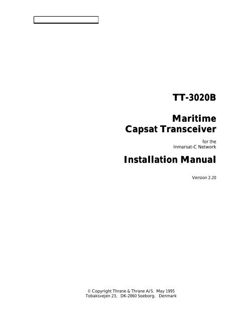
<strong>TT</strong>-<strong>3020B</strong><br />
Maritime<br />
Capsat Transceiver<br />
for the<br />
Inmarsat-C Network<br />
<strong>Installation</strong> <strong>Manual</strong><br />
© Copyright Thrane & Thrane A/S. May 1995<br />
Tobaksvejen 23, DK-2860 Soeborg. Denmark<br />
Version 2.20
Information in this document is subject to change without notice and does not represent<br />
a commitment on the part of Thrane & Thrane A/S.<br />
© 1995 Thrane & Thrane A/S. All right reserved. Printed in Denmark.<br />
Document Number <strong>TT</strong>-99-102829-220. Rele<strong>as</strong>e Date: 30MAY95.
Safety Summary<br />
The following general safety precautions must be observed<br />
during all ph<strong>as</strong>es of operation, service and repair of this<br />
equipment. Failure to comply with these precautions or with<br />
specific warnings elsewhere in this manual violates safety<br />
standards of design, manufacture and intended use of the<br />
equipment. Thrane & Thrane A/S <strong>as</strong>sumes no liability for the<br />
customers failure to comply with these requirements.<br />
GROUND THE EQUIPMENT<br />
To minimize shock hazard, the equipment ch<strong>as</strong>sis and cabinet<br />
must be connected to an electrical ground. For this purpose<br />
the equipment is equipped with a power connector including a<br />
ground terminal.<br />
DO NOT OPERATE IN AN EXPLOSIVE ATMOSPHERE<br />
Do not operate the equipment in the presence of flammable<br />
g<strong>as</strong>es or fumes. Operation of any electrical equipment in such<br />
an environment constitutes a definite safety hazard.<br />
KEEP AWAY FROM LIVE CIRCUITS<br />
Operating personnel must not remove equipment covers.<br />
Component replacement and internal adjustment must be<br />
made by qualified maintenance personnel. Do not replace<br />
components with the power cable connected. Under certain<br />
conditions, dangerous voltages may exist even with the power<br />
cable removed. To avoid injuries, always disconnect power<br />
and discharge circuits before touching them.<br />
DO NOT SERVICE OR ADJUST ALONE<br />
Do not attempt internal service or adjustments unless another<br />
person, capable of rendering first aid resuscitation, is present.<br />
DO NOT SUBSTITUTE PARTS OR MODIFY<br />
EQUIPMENT<br />
Because of the danger of introducing additional hazards, do not<br />
substitute parts or perform any unauthorized modification to the<br />
equipment.
Table of Contents<br />
1. Introduction 1<br />
2. Equipment installation 2<br />
2.1 Introduction 2<br />
2.1.1 Initial inspection 2<br />
2.1.2 Packing list 3<br />
2.1.3 Storage 4<br />
2.1.4 Repacking for shipment 4<br />
2.2 Technical specifications 5<br />
2.3 Power requirements 7<br />
2.3.1 AC mains operation 7<br />
2.3.1.1 Integrated Capsat System 7<br />
2.3.1.2 Power connector 8<br />
2.3.2 Fuses 9<br />
2.3.3 Grounding 9<br />
Thrane & Thrane<br />
<strong>TT</strong>-<strong>3020B</strong><br />
Capsat Transceiver<br />
<strong>Installation</strong> <strong>Manual</strong><br />
2.4 <strong>TT</strong>-3001 Antenn<strong>as</strong> 11<br />
2.4.1 Antenna types 11<br />
2.4.1.1 <strong>TT</strong>-3001B Option 001 Maritime Antenna 11<br />
2.4.2 Mounting bracket 12<br />
2.4.3 Antenna connector 12<br />
2.4.4 Antenna cable 12<br />
2.4.5 Mounting considerations 13<br />
2.4.5.1 <strong>TT</strong>-3001B-opt. 001 Maritime Antenna 13<br />
2.4.6 Safety Distance for Antenna Units 15<br />
2.5 <strong>TT</strong>-<strong>3020B</strong> Capsat Transceiver 16<br />
2.5.1 Mounting bracket 16<br />
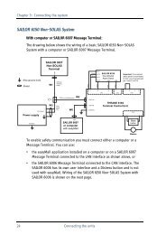
2.5.2 Communication port 16<br />
2.5.2.1 Baudrate and protocol settings 16<br />
2.5.2.2 X4 Connector interface 17<br />
2.5.2.3 Interfacing to peripherals 17<br />
2.5.2.3.1 <strong>TT</strong>-3606A Message Terminal 18<br />
2.5.2.3.2 IBM Compatible PC (Personal Computer) 18<br />
2.5.2.3.3 Computerized equipment 18<br />
2.5.2.3.4 Flow control 19<br />
2.5.3 T-Bus Connector 19<br />
2.5.3.1 Changing port X5 to input NMEA 0183 data 20<br />
2.5.3.2 Changing port X5 to output NMEA 0183 data 20<br />
2.5.3.3 Changing port X5 to T-Bus communication 20<br />
2.5.4 Switch settings 21<br />
2.5.5 Jumper configurations 22<br />
2.5.5.1 Default configuration 22<br />
2.5.6 Clock battery back-up 22<br />
2.5.7 NMEA 0183 Navigational Interface 23<br />
2.5.7.1 NMEA 0183 Reception 23<br />
2.5.7.2 NMEA 0183 Transmission 24<br />
30MAY95 Page i
Thrane & Thrane<br />
<strong>TT</strong>-<strong>3020B</strong><br />
Capsat Transceiver<br />
<strong>Installation</strong> <strong>Manual</strong><br />
2.6 <strong>TT</strong>-3606A Message Terminal (optional) 26<br />
2.6.1 Communication port 26<br />
2.6.2 Printer port 26<br />
2.6.3 VDU Interface 27<br />
2.6.3.1 <strong>TT</strong>-3602D SVGA Monitor 27<br />
2.6.3.2 <strong>TT</strong>-3680M DC to DC Converter (70Watt) 28<br />
2.6.4 <strong>TT</strong>-3601A keyboard 28<br />
2.7 <strong>TT</strong>-3680A/B Power Supply (optional) 29<br />
2.7.1 <strong>TT</strong>-3680A Power Supply (80 Watt) 29<br />
2.7.2 <strong>TT</strong>-3680B Power Supply (200 Watt) 29<br />
2.8 <strong>TT</strong>-3608A Hard Copy Printer 30<br />
2.8.1 Mounting plate 30<br />
2.9 <strong>TT</strong>-3042B Remote Alarm 32<br />
2.10 Built-in GPS (optional) 32<br />
2.11 General interconnect information 34<br />
3. System Generation 35<br />
3.1 Introduction 35<br />
3.2 Terminal preparation 36<br />
3.2.1 <strong>TT</strong>-3606A Message Terminal 36<br />
3.2.2 IBM Compatible PC 36<br />
3.2.3 Computerized equipment/handheld terminals 36<br />
3.3 Entering the System Generation 37<br />
3.4 The system generation menu 37<br />
3.4.1 Entering your mobile type and number 38<br />
3.4.1.1 F<strong>as</strong>t access to the Mobile Type 38<br />
3.5 Leaving the system generation 40<br />
4. Commissioning of the equipment 41<br />
4.1 Introduction 41<br />
4.2 The first login (commissioning) 42<br />
4.3 Overview of a Link Test 42<br />
4.4 Details of a Link Test 43<br />
4.5 Commissioned status 44<br />
4.6 Uncommissioned status 44<br />
Page ii 30MAY95
1. Introduction<br />
Thrane & Thrane<br />
<strong>TT</strong>-<strong>3020B</strong><br />
Capsat Transceiver<br />
<strong>Installation</strong> <strong>Manual</strong><br />
This manual provides instructions for installing, configuring and testing of a <strong>TT</strong>-3000<br />
Integrated Capsat System that includes a model <strong>TT</strong>-<strong>3020B</strong> Capsat Transceiver.<br />
The various Capsat Systems available from Thrane & Thrane are decribed in the manual<br />
Integrated Capsat Systems. Ple<strong>as</strong>e consult this manual if your uncertain what kind of<br />
system you will be installing.<br />
A wide variety of options and accessories may be linked together with the Capsat<br />
Transceiver, and the specific installation and configuring of these are to be found in<br />
their respective Reference <strong>Manual</strong>s.<br />
The relevant cabinet drawings and mounting information illustrations are found in the<br />
back of this manual.<br />
30MAY95 Page 1
Thrane & Thrane<br />
<strong>TT</strong>-<strong>3020B</strong><br />
Capsat Transceiver<br />
<strong>Installation</strong> <strong>Manual</strong><br />
2. Equipment installation<br />
2.1 Introduction<br />
This chapter provides specific information enabling you to install the Model <strong>TT</strong>-<strong>3020B</strong><br />
Capsat Transceiver into your own system, with minimal effort. The default, or factory<br />
configuration is described, together with procedures for altering this configuration.<br />
2.1.1 Initial inspection<br />
WARNING<br />
To avoid hazardous electrical shock, do not perform electrical<br />
tests if there is any sign of shipping damage to any portion of<br />
the front or rear panel or the outer cover. Read the safety<br />
summary at the front of this manual before installing or<br />
operating the <strong>TT</strong>-<strong>3020B</strong> Transceiver.<br />
Inspect the shipping carton immediately upon receipt for evidence of mishandling<br />
during the transit. If the shipping carton is severely damaged or waterstained request<br />
that the carrier's agent be present when opening the carton. Save the carton packing<br />
material for future use.<br />
Contents of the shipment should be <strong>as</strong> listed in the packing list below. If the contents<br />
are incomplete, if there is mechanical damage or defect, or if the <strong>TT</strong>-<strong>3020B</strong> Capsat<br />
Transceiver does not work properly, notify your dealer.<br />
After you unpack the <strong>TT</strong>-<strong>3020B</strong> Capsat Transceiver , inspect it thoroughly for hidden<br />
damage and loose components or fittings.<br />
� Inspect the cable harness for stress, loose or broken wires, or broken cable tires.<br />
� Examine all the components for loose or missing hardware. Tighten all loose<br />
hardware.<br />
� Remove loose debris from the cabinet interior.<br />
Page 2 30MAY95
2.1.2 Packing list<br />
Your Transceiver unit comes in a box with the following parts:<br />
Thrane & Thrane<br />
<strong>TT</strong>-<strong>3020B</strong><br />
Capsat Transceiver<br />
<strong>Installation</strong> <strong>Manual</strong><br />
Part number Item<br />
s<br />
Part Name Use<br />
403022-001 1 <strong>TT</strong>-<strong>3020B</strong> Capsat Transceiver<br />
52-200145-048 12 HCF 1876 screw, pozi, Fitting the angle or distance<br />
mushroom, 4x8mm<br />
mountings<br />
33-200192-120 2 Fuse, 12A mT Spare<br />
31-200098-009 1 Connector, D 9-pin male Spare<br />
31-200100-009 1 House, D 9-pin Spare<br />
31-200472-058 1 Connector, BNC Solder,<br />
Male<br />
Spare<br />
37-101098 1 Battery Cable, 2m, 1.5mm2 Connecting Transceiver to<br />
Power Supply<br />
61-100823 1 PC Cable 9-9 Pin, 2m Connecting Transceiver to PC<br />
or Message Terminal<br />
37-201237-925 1 PC-Adaptor 9/25 pin Connecting Transceiver to PC<br />
41-100742 2 Distance, Mounting Fitting Message Terminal to<br />
Transceiver<br />
41-100562 2 Angle, Mounting Fiiting Transceiver or<br />
Message Terminal to desk or<br />
console<br />
40-10202-002 1 Diskette, 3½": <strong>TT</strong>-10202B<br />
Capsat Program<br />
For PC<br />
98-403020-002 1 <strong>TT</strong>-3000 Capsat System<br />
Reference <strong>Manual</strong> including<br />
the following:<br />
Integrated Capsat Systems<br />
Operators Guide<br />
This manual<br />
1 Transceiver Test Sheet<br />
1 Inmarsat-C Commissioning<br />
Application Form<br />
30MAY95 Page 3
Thrane & Thrane<br />
<strong>TT</strong>-<strong>3020B</strong><br />
Capsat Transceiver<br />
<strong>Installation</strong> <strong>Manual</strong><br />
The Antenna is shipped in a separate box.<br />
69-102881 1 <strong>TT</strong>-3001B Antenna Unit<br />
51-200833-003 1 Unbraco Key, Steel N3 For antenna mounting<br />
51-200834-006 1 Unbraco Key, Steel N6 For antenna mounting<br />
1 Self-bonding tape, 30cm For sealing the antenna<br />
connector<br />
1 Description for fitting selfbonding<br />
tape<br />
403020-941 1 Antenna cable, 5m<br />
Table 1: Packing list.<br />
2.1.3 Storage<br />
The <strong>TT</strong>-<strong>3020B</strong> may be stored or shipped in temperatures within the limits -40° C to +80°<br />
C. It is advisable to protect the <strong>TT</strong>-<strong>3020B</strong> from extreme temperature variation which can<br />
cause excessive condensation. It is recommended that the <strong>TT</strong>-<strong>3020B</strong> is unpacked<br />
immediately on delivery.<br />
2.1.4 Repacking for shipment<br />
The shipping carton for the <strong>TT</strong>-<strong>3020B</strong> h<strong>as</strong> been carefully designed to protect the<br />
transceiver and its accessories during shipment. This carton and its <strong>as</strong>sociated packing<br />
material should be used if repacking for shipment. Attach a tag indicating the type of<br />
service required, a failure description, return address, model number and full serial<br />
number. Mark the carton FRAGILE to ensure careful handling.<br />
If the original shipping carton is not available, the following general instructions should<br />
be used for repacking with commercially available material.<br />
1. Wrap the <strong>TT</strong>-<strong>3020B</strong> in heavy paper or pl<strong>as</strong>tic. Attach a tag indicating the type of<br />
service required, return address, model number and full serial number.<br />
2. Use a strong shipping container, e.g. a double walled carton of 160 kg test material.<br />
3. Protect the front- and rear panel with cardboard and insert a 7 cm to 10 cm layer of<br />
shock absorbing material between all surfaces of the equipment and the sides of the<br />
container.<br />
4. Seal the shipping container securely.<br />
5. Mark the shipping container FRAGILE to ensure careful handling.<br />
Page 4 30MAY95
2.2 Technical specifications<br />
Thrane & Thrane<br />
<strong>TT</strong>-<strong>3020B</strong><br />
Capsat Transceiver<br />
<strong>Installation</strong> <strong>Manual</strong><br />
Model <strong>TT</strong>-<strong>3020B</strong><br />
General Specifications Meets or exceeds all INMARSAT<br />
specifications for the Inmarsat-C<br />
Network and GMDSS requirements.<br />
Transmit Frequency 1626.5 to 1646.5 MHz.<br />
Receive Frequency 1530.0 to 1545.0 MHz.<br />
Channel Spacing 5 kHz.<br />
Modulation 1200 symbols/sec BPSK.<br />
Ambiquity Resolution Unique word.<br />
Coding R 1/2 K=7 convolutional code,<br />
(interleaved code symbols RX).<br />
DataRate 600 bit/sec.<br />
RX Frame Length 8.64 seconds.<br />
TX Signalling Access Mode Slotted ALOHA.<br />
TX Message Channel TDMA & FDMA,interleaved code<br />
symbol.<br />
Antenna Interface Standard 50 Ohm female N-connnector,<br />
max 100 meter cable.<br />
GPS Interface 50 dB antenna amplification, 50 Ohm<br />
female SMA-connector output for GPS<br />
antenna<br />
Terminal Interface CCI<strong>TT</strong> Rec.V.24/28, 100-9600 Baud IA-5<br />
code, DB-9F connector.<br />
Printer Interface Standard parallel Centronics, DB-25F<br />
connector.<br />
Navigator and Alarm Interface CCI<strong>TT</strong> Rec. V.10 Special with NMEA-<br />
0183 interface and multidrop<br />
addressing, female BNC-connector,<br />
max.100 meter cable.<br />
System Setup EEPROM programming from operator<br />
terminal<br />
DC Power Source 10.5 to 32 V floating DC<br />
RX: 9.5 W<br />
TX: 80 W<br />
Ambient Temperature -25°C to 55°C operating<br />
-40°C to 80°C storage.<br />
Electronic Unit Mounting Flange mounting with optional 19" rack<br />
bracket.<br />
Dimensions H x W x D 62mm x 214mm x 279mm.<br />
Weight 3.2 Kg<br />
30MAY95 Page 5
Thrane & Thrane<br />
<strong>TT</strong>-<strong>3020B</strong><br />
Capsat Transceiver<br />
<strong>Installation</strong> <strong>Manual</strong><br />
Maritime Antenna<br />
<strong>TT</strong>-3001B Opt. 001<br />
Inmarsat-C/GPS omnidirectional<br />
antenna, RHC polarized.<br />
G/T: -23 dB/K<br />
EIRP: 14 dBW ± 2dB at 5° elevation.<br />
Temperature: -35°C to55°C operating,<br />
-40°C to 80°C storage.<br />
Dimensions (H x G): 237 mm x 150 mm<br />
conical ex. mounting.<br />
Weight 2.2 Kg.<br />
Solar Radiation Infra-red radiation 500W/m2 (EME).<br />
Relative Humidity 95% non-condensing at 40°C.<br />
Precipitation Up to 50 mm/hour, droplet size 0.5 to<br />
4.5 mm (EME).<br />
Ice Up to 25 mm (EME).<br />
Wind Up to 200 km/hour (maritime antenna).<br />
Vibration Operational Random 5-20 Hz: 0.02 g 2 /Hz<br />
20-150 Hz: -3dB/oct. (1.0g RMS).<br />
Vibration Survival Random 5-20 Hz: 0.05 g 2 /Hz<br />
20-150 Hz: -3dB/oct. (1.7g RMS).<br />
Shock Half sine 20g/11ms<br />
Antenna Mounting (Maritime) Standard 1.5" tube mounting.<br />
Other Antenn<strong>as</strong> Ple<strong>as</strong>e refer to dedicated brochures.<br />
Inmarsat-C Protocol support Message transmission and reception<br />
with IA-5, ITA-2 and binary transfer<br />
to/from the following destinations:<br />
Telex<br />
PSTN (telephone modems and fax<br />
modems)<br />
PSDN (X.25 network)<br />
EGC message reception with<br />
automatical geographical area selection<br />
Polling and datareporting with<br />
automatic transmission of position<br />
reports down to 1 per minute.<br />
Special Access Codes<br />
B<strong>as</strong>ic X.400<br />
DNID Messaging<br />
Program Unreserved Datareporting<br />
Pre-<strong>as</strong>signed Datareporting<br />
GMDSS facilities.<br />
Transmit message size: Max 32Kbyte<br />
Receive storage: 128 Kbyte<br />
Table 2: Technical specifications.<br />
As our products are under continuous research and development, any information may<br />
change without prior notice.<br />
Page 6 30MAY95
2.3 Power requirements<br />
Thrane & Thrane<br />
<strong>TT</strong>-<strong>3020B</strong><br />
Capsat Transceiver<br />
<strong>Installation</strong> <strong>Manual</strong><br />
Depending on your particular <strong>TT</strong>-3000 System you will need AC supply or a DC supply.<br />
A <strong>TT</strong>-3000 Integrated Capsat System operates on either 115 VAC, 220 VAC or floating<br />
DC in the range from 10.5-32 Volt. The total power consumption varies with the<br />
particular system in question.<br />
As a guide-line, ple<strong>as</strong>e note the power consumption of the following equipment:<br />
<strong>TT</strong>-1542B Call Alarm 0.6 W<br />
<strong>TT</strong>-3022A Capsat Transceiver incl. antenna 9.5W RX 80W TX<br />
<strong>TT</strong>-3602D SVGA Monitor 60 W<br />
<strong>TT</strong>-3606A Message Terminal, incl keyboard. 8W<br />
<strong>TT</strong>-3608A Printer 33W<br />
<strong>TT</strong>-3042B Remote Alarm 2.5W 7W Print<br />
Option 005 Built-in GPS 2W<br />
Table 3: Capsat System component power requirements.<br />
2.3.1 AC mains operation<br />
As the <strong>TT</strong>-<strong>3020B</strong> Capsat Transceiver is designed to work on floating DC ranging from<br />
10.5 - 32 Volt, an AC/DC converter is needed in c<strong>as</strong>e the Transceiver is subject to work<br />
in AC environments.<br />
2.3.1.1 Integrated Capsat System<br />
For a <strong>TT</strong>-3000 Integrated Capsat System with an IBM compatible PC we recommend the<br />
<strong>TT</strong>-3680A Power Supply.<br />
The <strong>TT</strong>-3680A Power Supply operates on either 115 VAC or 230 VAC. (internally<br />
selectable) and supplies 24 VDC/96 Watt <strong>as</strong> a maximum.<br />
The <strong>TT</strong>-3680A will adjust the DC output level (10.5 - 32 Volt) according to the total load.<br />
The <strong>TT</strong>-3680A Power Supply may be connected to the emergency batteries offering<br />
automatic switch-over to DC in c<strong>as</strong>e of a mains line drop-out.<br />
For a <strong>TT</strong>-3000 Integrated Capsat System with a <strong>TT</strong>-3608A Message Terminal we<br />
recommend the <strong>TT</strong>-3680B Power Supply.<br />
30MAY95 Page 7
Thrane & Thrane<br />
<strong>TT</strong>-<strong>3020B</strong><br />
Capsat Transceiver<br />
<strong>Installation</strong> <strong>Manual</strong><br />
The <strong>TT</strong>-3680B Power Supply operates on either 115 VAC or 230 VAC. (internally<br />
selectable) and supplies 24 VDC/200 Watt <strong>as</strong> a maximum.<br />
The <strong>TT</strong>-3680B will adjust the DC output level (10.5 - 32 Volt) according to the total load.<br />
The <strong>TT</strong>-3680B Power Supply may be connected to the emergency batteries offering<br />
automatic switch-over to DC in c<strong>as</strong>e of a mains line drop-out.<br />
2.3.1.2 Power connector<br />
The battery connector matches the Thrane & Thrane standards for battery connectors.<br />
Regardless whether the unit is designed to work on floating DC or modified to match<br />
your DC requirements the pin <strong>as</strong>signment of the DC/Battery power connector looks like<br />
this:<br />
Pin Name Signal Description<br />
1 SGND Safety Ground<br />
2 SUP+ Supply Voltage, positive terminal<br />
3 SUP- Supply Voltage, negative terminal<br />
4 ON/OFF Remote ON/OFF Switch<br />
Table 4: <strong>TT</strong>-<strong>3020B</strong> Capsat Transceiver DC Power Connector pin <strong>as</strong>signment<br />
Pin 4 is a unique feature for the <strong>TT</strong>-<strong>3020B</strong> Capsat Transceiver.<br />
When this pin is left floating the Transceiver is turned off, but if pin 4 is shorted to the<br />
negative terminal of the battery or DC-supply the Transceiver will switch on. This<br />
makes it possible for other equipment to perform remote power control of the <strong>TT</strong>-<strong>3020B</strong>.<br />
The remote power control can be triggered by an external relay or solid state switch.<br />
The battery connection is floating, i.e. there is no galvanic connection from any of the<br />
battery poles to the cabinet frame.<br />
Page 8 30MAY95
2.3.2 Fuses<br />
Thrane & Thrane<br />
<strong>TT</strong>-<strong>3020B</strong><br />
Capsat Transceiver<br />
<strong>Installation</strong> <strong>Manual</strong><br />
In c<strong>as</strong>e you experience that a fuse needs replacement, ple<strong>as</strong>e check that the equipment<br />
h<strong>as</strong> not been exposed to physical damage before fuse replacement takes place.<br />
WARNING<br />
To avoid hazardous electrical shock, do not perform electrical<br />
tests if there is any sign of shipping damage to any portion of<br />
the front or rear panel or the outer cover. Read the safety<br />
summary at the front of this manual before installing or<br />
operating the <strong>TT</strong>-<strong>3020B</strong> Transceiver.<br />
As a guide-line, ple<strong>as</strong>e note the fuse location of the following equipment:<br />
Equipment Location Fuse size<br />
<strong>TT</strong>-1542B Call Alarm No fuse available.<br />
<strong>TT</strong>-<strong>3020B</strong> Capsat<br />
Externally accessed, 12A mT.<br />
Transceiver incl. antenna located on the rear panel.<br />
<strong>TT</strong>-3602D SVGA Monitor External accessed,<br />
located on the rear panel<br />
3.15A mT.<br />
<strong>TT</strong>-3680M DC to DC External accessed, Input 10A mT.<br />
converter<br />
located on the front and<br />
the rear panel<br />
Output 1A mT.<br />
<strong>TT</strong>-3606A Message Externally accessed, 3.15A mT.<br />
Terminal, incl keyboard. located on the rear panel.<br />
<strong>TT</strong>-3608A Printer Internally accessed,<br />
remove topcover.<br />
1.5A mT.<br />
<strong>TT</strong>-3680A Power Supply Internally accessed, 1A mT.<br />
(80 Watt)<br />
remove topcover.<br />
<strong>TT</strong>-3680B Power Supply Internally accessed, 3.15A mT.<br />
(200 Watt)<br />
remove topcover.<br />
<strong>TT</strong>-3042B Remote Alarm Externally accessed,<br />
located on the rear panel.<br />
1A mT.<br />
Table 5: Capsat System fuses<br />
The <strong>TT</strong>-3680A/B Power Supply may blow an internal fuse in c<strong>as</strong>e you power up the<br />
entire Integrated System with all DC units turned on. It is therefore recommended to<br />
power up the DC units one by one.<br />
2.3.3 Grounding<br />
RF-grounding of an Integrated Capsat System requires special attention.<br />
30MAY95 Page 9
Thrane & Thrane<br />
<strong>TT</strong>-<strong>3020B</strong><br />
Capsat Transceiver<br />
<strong>Installation</strong> <strong>Manual</strong><br />
Each unit shall have its own individual low-inductance earth connection. The use of a<br />
common busbar for grounding is not recommended <strong>as</strong> this can lead to unwanted<br />
common-mode coupling effects.<br />
The ground should be connected to the cabinets metal frame to provide a return path<br />
for fault currents due to equipment malfunction or external faults such <strong>as</strong> lightning faults.<br />
Interconnecting cables must be well screened.<br />
Page 10 30MAY95
2.4 <strong>TT</strong>-3001 Antenn<strong>as</strong><br />
2.4.1 Antenna types<br />
Figure 1: Maritime antenna.<br />
Thrane & Thrane<br />
<strong>TT</strong>-<strong>3020B</strong><br />
Capsat Transceiver<br />
<strong>Installation</strong> <strong>Manual</strong><br />
Your Integrated Capsat System h<strong>as</strong> been delivered with a <strong>TT</strong>-3001B Option 001<br />
Maritime Antenna. The antenna is compatible electrically with the earlier <strong>TT</strong>-3001A<br />
antenna with or without Option 003 (GPS signal filter).<br />
2.4.1.1 <strong>TT</strong>-3001B Option 001 Maritime Antenna<br />
This is an omni-directional antenna with built-in<br />
� High Power Amplifier, HPA, <strong>TT</strong> part no. 60-102195<br />
� Low Noise Amplifier, LNA, <strong>TT</strong> part no. 60-101805<br />
� Combiner, <strong>TT</strong> part no. 60-102193<br />
� Diplexer, <strong>TT</strong> part no. 69-101916<br />
� Maritime Antenna element, <strong>TT</strong> part no. 69-102192<br />
The antenna is very compact and is designed to operate in a corrosive environment and<br />
in extreme weather conditions without any service. It h<strong>as</strong> a modular construction that<br />
allows e<strong>as</strong>y exchange of antenna elements. The antenna housing is sealed with tamperresistant<br />
TORX screws, so that it can only be dis<strong>as</strong>sembled by Thrane & Thrane<br />
approved technicians.<br />
The antenna is fully compatible with the Inmarsat-C GMDSS specifications, and can also<br />
receive GPS signals while not transmitting.<br />
30MAY95 Page 11
Thrane & Thrane<br />
<strong>TT</strong>-<strong>3020B</strong><br />
Capsat Transceiver<br />
<strong>Installation</strong> <strong>Manual</strong><br />
2.4.2 Mounting bracket<br />
The omnidirectional maintenance free antenna unit must be mounted in a high location<br />
with direct line-of-sight to the satellites.<br />
Illustration of the 1½" Adaptor for mouting on a pole is enclosed in the back of this<br />
manual.<br />
The Adaptor may be removed by loosening the three Allan screws fitting the bracket to<br />
the antenna.<br />
2.4.3 Antenna connector<br />
"N" type connectors are available from manufacturers like:<br />
Suhner, Radial, Omnispectra, Kings, etc.<br />
2.4.4 Antenna cable<br />
Your Integrated Capsat System, h<strong>as</strong> been delivered with a 5m coaxial cable, preterminated<br />
with a standard connector of "N" type.<br />
The specifications requires that the total maximal attenuation at 1.65 GHz must be less<br />
than 16 dB, and the maximal total (short-circuited in one end) DC resistance must not<br />
exceed 0.8 Ohms.<br />
In c<strong>as</strong>e the antenna cable is to be produced on site, the cable type should match the<br />
below listed guide-lines:<br />
Range (m) Cable type no. Connector type no.<br />
(Suhners)<br />
1 - 5 RG-223U, 5.5 mm (Cable enclosed)<br />
6 - 40 RG-214U, 10.8 mm 11N-50-7-44<br />
41 - 80 SA7272, 10.0 mm 11N-50-7-35<br />
81 - 100 SA12272, 15.0 mm 11N-50-12-35C<br />
Table 6: <strong>TT</strong>-<strong>3020B</strong> Capsat Transceiver Antenna Cable types<br />
All antenna cables types are double shielded.<br />
The antenna cable may run together with radar or navigator cables. Separate cable<br />
ditch is not required.<br />
Page 12 30MAY95
Thrane & Thrane<br />
<strong>TT</strong>-<strong>3020B</strong><br />
Capsat Transceiver<br />
<strong>Installation</strong> <strong>Manual</strong><br />
If you install your system in a permanent location, we recommend that you, after the<br />
installation of the antenna, wrap the connector with the enclosed self-bonding tape,<br />
disabling water from penetrating the connection.<br />
2.4.5 Mounting considerations<br />
2.4.5.1 <strong>TT</strong>-3001B-opt. 001 Maritime Antenna<br />
When installing the Maritime Antenna you should find a location on the vessel that is <strong>as</strong><br />
free from obstructions <strong>as</strong> possible. Also you should maintain a certain distance to other<br />
antenn<strong>as</strong>, especially radar installations. Normally the best place for the antenna would<br />
be above radar scanning antenn<strong>as</strong>. The following safe distances should be maintained:<br />
Distance to HF antenn<strong>as</strong> > 5 m<br />
Distance to VHF antenn<strong>as</strong> > 4 m<br />
Distance to magnet comp<strong>as</strong>s > 3 m<br />
The antenna is designed to provide satellite coverage even when the vessel h<strong>as</strong> pitch<br />
and roll movements up to 15°. To maintain this coverage the antenna should be free<br />
from obstructions in the area down to 15° below the horizon. Since this may not be<br />
possible in the fore and aft directions of the vessel, the clear area can be reduced to 5°<br />
below the horizon in the fore and aft directions and 15° below the horizon in the port<br />
and starboard directions. Any compromise in this recommendation will degrade<br />
performance.<br />
Horizon<br />
15°<br />
30MAY95 Page 13<br />
Zenith<br />
Capsat<br />
Obstructions should be below these lines<br />
Horizon<br />
Figure 2: <strong>TT</strong>-3001B Option 001 Maritime Antenna mounting.<br />
15°
Thrane & Thrane<br />
<strong>TT</strong>-<strong>3020B</strong><br />
Capsat Transceiver<br />
<strong>Installation</strong> <strong>Manual</strong><br />
If an obstruction such <strong>as</strong> a pole or a funnel is unavoidable, the following guidelines<br />
apply:<br />
The distance to the obstruction should large enough, so that the obstruction only covers<br />
3 degrees. This means that the safe distance is:<br />
Example:<br />
Safe distance = 20 * Diameter of obstruction<br />
Obstruction is a 4" pole. Diameter = 0.1 m. Safe distance is 20 * 0.1 m = 2 m<br />
Max. obstruction angle 3 degrees Capsat<br />
Figure 3: <strong>TT</strong>-3001B Option 001 Maritime Antenna mounting near pole or funnel.<br />
Page 14 30MAY95
2.4.6 Safety Distance for Antenna Units<br />
Thrane & Thrane<br />
<strong>TT</strong>-<strong>3020B</strong><br />
Capsat Transceiver<br />
<strong>Installation</strong> <strong>Manual</strong><br />
The safety levels for the Thrane & Thrane INMARSAT-C Antenna Units are b<strong>as</strong>ed on the<br />
ANSI standard C95.1-1982 "American National Standard Safety Levels With Respect to<br />
Human Exposure to Radio Frequency Electromagnetic Fields, 300 kHz to 100 GHz"<br />
This standard recommends the maximum power density at 1.6 GHz exposed to human<br />
beings not to exceed 5 mW/cm².<br />
At the maximum radiated output power from the INMARSAT-C Antenna (16 dBW EIRP)<br />
this corresponds to a minimum safety distance on 30 cm.<br />
To be sure that this distance is respected the Thrane & Thrane INMARSAT-C Antenna<br />
Units are provided with a label declaring a minimum safety distance on 2 feet (61 cm).<br />
In the future standards from the European Telecommunication Standard Institute (ETSI)<br />
concerning 1.5/1.6 GHz Satellite Earth Stations the recommendation will be maximum<br />
8W/m² (0.8 mW/cm²). This tighter recommendations correspond to a minimum safety<br />
distance on 60 cm at 16 dBW, so these future European recommendations are also<br />
covered within the declared minimum safety distance on 2 feet (62 cm).<br />
30MAY95 Page 15
Thrane & Thrane<br />
<strong>TT</strong>-<strong>3020B</strong><br />
Capsat Transceiver<br />
<strong>Installation</strong> <strong>Manual</strong><br />
2.5 <strong>TT</strong>-<strong>3020B</strong> Capsat Transceiver<br />
2.5.1 Mounting bracket<br />
Figure 4: <strong>TT</strong>-<strong>3020B</strong> Capsat Transceiver<br />
The <strong>TT</strong>-<strong>3020B</strong> Capsat Transceiver is supplied with an universal mounting bracket (41-<br />
100562) which allows "over" or "under" mounting to e.g. a table or ceiling.<br />
It is recommended that the Transceiver is mounted in an open air location allowing the<br />
operator full access to the front panel in a distress situation.<br />
When the Transceiver is used with other Thrane & Thrane equipment such <strong>as</strong> the<br />
<strong>TT</strong>-3606A Message Terminal or the <strong>TT</strong>-3210A Radiotelex Modem, stacked mounting may<br />
be achieved using mounting bracket 41-100742.<br />
It is strongly recommended not to stack mount the <strong>TT</strong>-<strong>3020B</strong> Capsat Transceiver with<br />
the <strong>TT</strong>-3680A Power Supply because of the heat generation from this unit.<br />
2.5.2 Communication port<br />
The <strong>TT</strong>-<strong>3020B</strong> Capsat Transceiver communicates with a controller device via the<br />
standard EIA RS-232D ports, located on the rear panel at X4.<br />
2.5.2.1 Baudrate and protocol settings<br />
The <strong>TT</strong>-<strong>3020B</strong> accepts the following:<br />
Page 16 30MAY95
Thrane & Thrane<br />
<strong>TT</strong>-<strong>3020B</strong><br />
Capsat Transceiver<br />
<strong>Installation</strong> <strong>Manual</strong><br />
Baud rates Protocol settings Handshake<br />
110 Baud 7/8 databits Hardware<br />
150 Baud No/Even/Odd parity Using DTR and CTS<br />
300 Baud<br />
600 Baud<br />
1200 Baud<br />
2400 Baud<br />
4800 Baud<br />
9600 Baud<br />
1/2 stopbits<br />
Table 7: Automatic baudrate settings.<br />
The serial port communication parameters are factory programmed to:<br />
4800 Baud, 8 databits, no parity, 1 stopbit<br />
Ple<strong>as</strong>e refer to chapter section 3.3 to alter the baudrate and the protocol settings by<br />
means of Automatic Baud Rate Recognition.<br />
Alternatively these settings may be customer defined.<br />
2.5.2.2 X4 Connector interface<br />
The <strong>TT</strong>-<strong>3020B</strong> uses the the following signals (marked with a � in the Used column):<br />
Name Signal description 9-Pin Used Levels Direction<br />
DCD Data Carrier Detect 1 RS-232/423 ��<br />
RxD Received Data 2 � RS-232/423 ��<br />
TxD Transmitted Data 3 � RS-232 ��<br />
DTR Data Terminal Ready 4 � RS-232 ��<br />
GND Ground 5 �<br />
DSR Data Set Ready 6 � RS-232/423 ��<br />
RTS Request To Send 7 RS-232 ��<br />
CTS Clear To Send 8 � RS-232/423 ��<br />
RI Ring Indicator 9 � RS-232/423 ��<br />
Table 8: <strong>TT</strong>-<strong>3020B</strong> X4 pin <strong>as</strong>signment.<br />
The �� symbol means that the signal is generated by the Transceiver.<br />
For full operating specifications for the serial interface, you are kindly requested to<br />
refer to the CCI<strong>TT</strong> Rec. V24, the EIA RS-423C or EIA RS-232D.<br />
2.5.2.3 Interfacing to peripherals<br />
The transceiver may be used in numerous configurations for operation with equipment<br />
like:<br />
30MAY95 Page 17
Thrane & Thrane<br />
<strong>TT</strong>-<strong>3020B</strong><br />
Capsat Transceiver<br />
<strong>Installation</strong> <strong>Manual</strong><br />
� <strong>TT</strong>-3606A Message Terminal.<br />
� IBM Compatible PC with a <strong>TT</strong>-10202A/B Message Terminal emulating software.<br />
� Computerized equipment.<br />
� Handheld terminals, etc.<br />
2.5.2.3.1 <strong>TT</strong>-3606A Message Terminal<br />
To Interface the <strong>TT</strong>-<strong>3020B</strong> to a <strong>TT</strong>-3606A Message Terminal, simply use the 30cm<br />
communication cable enclosed in the delivery (part no <strong>TT</strong>-61 100921).<br />
An extended serial communication cable should not exceed 100 meters <strong>as</strong> the <strong>TT</strong>-3606A<br />
works on 4800 Baud using the RS-423 standard.<br />
2.5.2.3.2 IBM Compatible PC (Personal Computer)<br />
Interfacing the <strong>TT</strong>-<strong>3020B</strong> to a IBM Compatible PC, simply use the communication cable<br />
enclosed in the delivery: Either 9-9 pin (part no <strong>TT</strong>-61 100823) or 9-25 pin (part no<br />
<strong>TT</strong>-61 101034).<br />
An extended communication cable should not exceed 8 meters <strong>as</strong> the <strong>TT</strong>-10202A<br />
Message Terminal emulating software works on 4800 Baud using the RS-232C standard.<br />
As the PC hardware normally does not conform to the RS-423 standard the maximum<br />
length of the connection cable is less than for the <strong>TT</strong>-3606A solution.<br />
As the <strong>TT</strong>-<strong>3020B</strong> rely on the CTS and DTR hardware handshake signals it is very<br />
important that the PC you use is IBM hardware compatible with respect to the serial<br />
communications interface.<br />
2.5.2.3.3 Computerized equipment<br />
Before connecting the <strong>TT</strong>-<strong>3020B</strong> to any computerized equipment you are recommended<br />
to consult the computer installation manual to check the pin <strong>as</strong>signment of the serial<br />
communication port.<br />
Your <strong>TT</strong>-<strong>3020B</strong> is configured <strong>as</strong> Data Communications Equipment (DCE).<br />
Most computers are configured <strong>as</strong> Data Terminal Equipment (DTE).<br />
If this is the c<strong>as</strong>e for the particular computer, you will probably be able to provide the<br />
necessary connections with a multi-wire cable, <strong>as</strong> shown in the tables below:<br />
Page 18 30MAY95
9 Pin Connector<br />
Transceiver Computer<br />
2 2<br />
3 3<br />
4 4<br />
5 5<br />
6 6<br />
8 8<br />
9 9<br />
25 Pin Connector<br />
Transceiver Computer<br />
2 3<br />
3 2<br />
4 20<br />
5 7<br />
6 6<br />
8 5<br />
9 22<br />
Figure 5: <strong>TT</strong>-<strong>3020B</strong> connection to computer<br />
Thrane & Thrane<br />
<strong>TT</strong>-<strong>3020B</strong><br />
Capsat Transceiver<br />
<strong>Installation</strong> <strong>Manual</strong><br />
Signal Name<br />
30MAY95 Page 19<br />
RxD<br />
TxD<br />
DTR<br />
Ground<br />
If your computer is configured <strong>as</strong> DCE you will have to cross the wires running from pin<br />
2 and pin 3 of your <strong>TT</strong>-<strong>3020B</strong> to the computer. Pin 5 from the <strong>TT</strong>-<strong>3020B</strong> will still connect<br />
<strong>as</strong> shown.<br />
2.5.2.3.4 Flow control<br />
DSR<br />
The <strong>TT</strong>-<strong>3020B</strong> optionally uses either hardware or software flow control.<br />
2.5.2.3.4.1 Hardware flow control<br />
Hardware flow control is accomplished by using the DTR and CTS signals.<br />
2.5.2.3.4.2 Software flow control<br />
Software flow control is accomplished by connecting the DTR and CTS, allowing both<br />
<strong>TT</strong>-<strong>3020B</strong> and the peripheral to control data flow by means XON XOFF.<br />
ENQ/ACK cannot be used.<br />
2.5.3 T-Bus Connector<br />
The T-Bus port X5 on the back panel of the <strong>TT</strong>-<strong>3020B</strong> Transceiver can be used for either<br />
� Thrane & Thrane T-Bus communication<br />
when connecting to the <strong>TT</strong>-3042B Remote Alarm or other T-Bus devices<br />
� The International NMEA 0183 communication standard input and output when<br />
connecting to a commercial available navigator device or using the built-in GPS is<br />
installed and in navigation mode.<br />
The factory default is T-Bus communication.<br />
CTS<br />
RI
Thrane & Thrane<br />
<strong>TT</strong>-<strong>3020B</strong><br />
Capsat Transceiver<br />
<strong>Installation</strong> <strong>Manual</strong><br />
The T-BUS connector, a standard BNC-type, is located on the rear panel of the<br />
transceiver and is marked X5. The inner conductor carries the data signals and the<br />
outer is the shield.<br />
2.5.3.1 Changing port X5 to input NMEA 0183 data<br />
If the <strong>TT</strong>-<strong>3020B</strong> will be used with a navigator using the NMEA standard, you must follow<br />
the below instructions to ensure proper operation:<br />
1. Turn off the <strong>TT</strong>-<strong>3020B</strong> .<br />
2. Place the <strong>TT</strong>-<strong>3020B</strong> upside-down, remove all 9 screws so that the bottom cover<br />
can be removed.<br />
3. Locate the switch array in the corner of the <strong>TT</strong>-<strong>3020B</strong> CPU board, and set switch 1<br />
and 3 in the OFF position. This selects NMEA input operation. Ple<strong>as</strong>e refer to<br />
figure 7 on page 21.<br />
2.5.3.2 Changing port X5 to output NMEA 0183 data<br />
If the <strong>TT</strong>-<strong>3020B</strong> will be used with an external device using the NMEA standard, you must<br />
follow the below instructions to ensure proper operation:<br />
1. Turn off the <strong>TT</strong>-<strong>3020B</strong> .<br />
2. Place the <strong>TT</strong>-<strong>3020B</strong> upside-down, remove all 9 screws so that the bottom cover<br />
can be removed.<br />
3. Locate the switch array in the corner of the <strong>TT</strong>-<strong>3020B</strong> CPU board, and set switch 1<br />
in the OFF position and switch 3 in the ON position. This selects NMEA output<br />
operation. Ple<strong>as</strong>e refer to figure 7 on page 21.<br />
2.5.3.3 Changing port X5 to T-Bus communication<br />
If the <strong>TT</strong>-<strong>3020B</strong> will be used with a <strong>TT</strong>-3042B Remote Alarm using the T-Bus standard,<br />
you must follow the below instructions to ensure proper operation:<br />
1. Turn off the <strong>TT</strong>-<strong>3020B</strong>.<br />
2. Place the <strong>TT</strong>-<strong>3020B</strong> upside-down, remove all 9 screws so that the bottom cover<br />
can be removed.<br />
3. Locate the switch array in the corner of the <strong>TT</strong>-<strong>3020B</strong> CPU board, and set switch 1<br />
in the ON position. This selects T-Bus operation. Ple<strong>as</strong>e refer to figure 7 on page<br />
21.<br />
Page 20 30MAY95
2.5.4 Switch settings<br />
Thrane & Thrane<br />
<strong>TT</strong>-<strong>3020B</strong><br />
Capsat Transceiver<br />
<strong>Installation</strong> <strong>Manual</strong><br />
For location of the DIP (Dual-in-line) Switch Array see the following figure.<br />
Figure 6: The DIP switches. Ple<strong>as</strong>e refer to figure 7 on page 21.<br />
Speaker<br />
U6 EEPROM<br />
U12 EPROM<br />
DIP Switches<br />
Power<br />
Printer T-Bus Console<br />
CPU<br />
Alarm<br />
Button<br />
GPS Module<br />
Set<br />
Button<br />
Power<br />
Button<br />
SW.1 T-Bus Mode<br />
SW.2 RPU Mode<br />
SW.3 NMEA 0183 Output<br />
SW.6 Service Mode<br />
DS.1 T-Bus Activity: Flickers<br />
DS.2 Frame Decode: Toggles every 16s<br />
DS.3 CPU Activity: Flickers<br />
DS.4 TX data<br />
TP.2 128 Hz Clock Adjustment<br />
U18 Viterbi EPROM<br />
Figure 7: <strong>TT</strong>-<strong>3020B</strong> CPU Board, No. <strong>TT</strong> 37-102819,<br />
showing the DIP Switch array.<br />
Most of the DIP switches inside the <strong>TT</strong>-<strong>3020B</strong> Capsat Transceiver are reserved for future<br />
use.<br />
30MAY95 Page 21
Thrane & Thrane<br />
<strong>TT</strong>-<strong>3020B</strong><br />
Capsat Transceiver<br />
<strong>Installation</strong> <strong>Manual</strong><br />
2.5.5 Jumper configurations<br />
Much of the flexibility of your <strong>TT</strong>-<strong>3020B</strong> Capsat Transceiver is due to the extensive use<br />
of operator programmable configuration parameters, enabling the user to adjust the<br />
<strong>TT</strong>-<strong>3020B</strong> to his specific application needs.<br />
Most of the configuration parameters are contained in a single integrated circuit, a nonvolatile<br />
EEPROM.<br />
However, some parameters must be programmed by means of hardware jumpers or<br />
straps on the main CPU board.<br />
These jumper settings may e<strong>as</strong>ily be altered from their factory configuration to match<br />
your particular application.<br />
2.5.5.1 Default configuration<br />
The figure below summarize the jumper configurations and their use.<br />
Jumper Default Function<br />
W3<br />
Enable 12V or 5V supply to external GPS antenna.<br />
Pos 1-2<br />
12V<br />
Pos 2-3<br />
5V<br />
Table 9: List of jumpers. You must not insert a jumper in any of the listed positions if you<br />
use an built-in GPS (option 005)..<br />
Warning:<br />
Do not attempt to change jumper settings unless you have thorough<br />
understanding of their meaning.<br />
2.5.6 Clock battery back-up<br />
The clock in the transceiver is permanently backed-up by an internal non-chargeable 3<br />
Volt lithium battery. The service life of this battery exceeds 5 years.<br />
If you turn off the <strong>TT</strong>-<strong>3020B</strong> Capsat Transceiver for a prolonged period this could drain<br />
your battery. If your status screen indicates "Error in CMOS clock" in the first line, you<br />
may need to change the battery.<br />
If the battery wears out it must be replaced by qualified service personnel.<br />
Ple<strong>as</strong>e remember to logout of the Inmarsat-C system if you turn off the <strong>TT</strong>-<strong>3020B</strong> Capsat<br />
Transceiver for a prolonged period.<br />
Page 22 30MAY95
2.5.7 NMEA 0183 Navigational Interface<br />
Thrane & Thrane<br />
<strong>TT</strong>-<strong>3020B</strong><br />
Capsat Transceiver<br />
<strong>Installation</strong> <strong>Manual</strong><br />
The following Navigators will provide suitable NMEA 0183 strings to the Capsat<br />
Transceiver.<br />
AP Navigator Professional APN5 GPS<br />
AP Navigator MK6<br />
Raytheon Raystar 920<br />
Furuno GP500 GPS<br />
Furuno GP1250 GPS<br />
Furuno GP70 GPS<br />
Navstar XR4 GPS<br />
Digital Northstar 800 Loran<br />
Micrologic Explorer GPS<br />
Trimble Navtrac XL<br />
Shipmate RS 5300 GPS<br />
Shipmate RS 4000 CC Decca<br />
Sperry 501 TR/GPS SatNav + Øverland interface unit UPL 2000<br />
Koden KGP 900 GPS<br />
Koden KGP 930 GPS<br />
Koden LR 771 Loran C<br />
2.5.7.1 NMEA 0183 Reception<br />
The NMEA 0183 Standard uses the ASCII alphabet to send strings with navigational data.<br />
This data can be read by the Transceiver via the T-Bus interface.<br />
The following is a list of the NMEA codes that the Transceiver will recognize.<br />
If the NMEA 0183 GLL string received by the Transceiver h<strong>as</strong> an empty field the position<br />
information will not be updated at all.<br />
GLL<br />
VTG<br />
VHW<br />
HDT<br />
HSC<br />
Geographic position, latitude and longitude<br />
If the NMEA 0183 GLL string received by the Transceiver h<strong>as</strong> an empty field the<br />
position information will not be updated.<br />
Heading (track) and speed information<br />
Heading and speed information<br />
Heading information<br />
Heading information<br />
30MAY95 Page 23
Thrane & Thrane<br />
<strong>TT</strong>-<strong>3020B</strong><br />
Capsat Transceiver<br />
<strong>Installation</strong> <strong>Manual</strong><br />
2.5.7.2 NMEA 0183 Transmission<br />
When you have a built-in GPS it is possible configure the Transceiver to send out NMEA<br />
0183 navigational data so that devices connected to the Transceiver via the T-Bus<br />
connector will benefit from the GPS information.<br />
To use NMEA output you must set:<br />
SWITCH 1 OFF and SWITCH 3 ON<br />
The following four strings:<br />
VTG<br />
GLL<br />
GGA<br />
ZDA<br />
Heading and speed information<br />
Geographic position, latitude and longitude<br />
Global Positioning System fix data (includes time of position)<br />
Time and date<br />
are sent out when the Transceiver h<strong>as</strong> a built-in GPS and it is in navigation mode. The<br />
time in the position strings and the Time-and-date string are always the same.<br />
The spacing between each block of data is 2 seconds and 0.5 seconds between GLL,<br />
GGA and ZDA strings when they are present.<br />
An example is:<br />
$GPVTG,000.,T,000.,M,00.0,N,00.0,K<br />
$GPGLL,5544.44,N,01228.64,E,121003,A<br />
$GPGGA,121003,5544.44,N,01228.64,E,1,04,1,37,M,,M,,<br />
$GPZDA,121003,19,02,1993,,<br />
The following three strings: VTG, GLL and GGA are sent out when the Transceiver h<strong>as</strong> a<br />
built-in GPS but it is in aquisition mode and the currently stored position is less than 24<br />
hours old. The time indicates that of the l<strong>as</strong>t known position. The course and speed are<br />
8 second mean values.<br />
An example is:<br />
$GPVTG,180.,T,180.,M,01.0,N,00.0,K<br />
$GPGLL,5544.45,N,01228.67,E,121059,<br />
$GPGGA,121059,5544.45,N,01228.67,E,0,00,1,23,M,,M,,<br />
The following three strings: VTG, GLL and GGA are sent out when the Transceiver h<strong>as</strong> a<br />
built-in GPS but it is in aquisition mode and the currently stored position is more than 24<br />
hours old. The time field is empty. The course and speed are 8 second mean values.<br />
An example is:<br />
Page 24 30MAY95
$GPVTG,139.,T,139.,M,02.0,N,00.0,K<br />
$GPGLL,5544.45,N,01228.68,E,,<br />
$GPGGA,,5544.45,N,01228.68,E,0,00,1,0,M,,M,,<br />
Thrane & Thrane<br />
<strong>TT</strong>-<strong>3020B</strong><br />
Capsat Transceiver<br />
<strong>Installation</strong> <strong>Manual</strong><br />
An empty GLL string is sent out when there is no built-in GPS or before the GPS module<br />
h<strong>as</strong> been started by the Transceiver.<br />
$GPGLL,,,,,,<br />
$GPGLL,,,,,,<br />
$GPGLL,,,,,,<br />
30MAY95 Page 25
Thrane & Thrane<br />
<strong>TT</strong>-<strong>3020B</strong><br />
Capsat Transceiver<br />
<strong>Installation</strong> <strong>Manual</strong><br />
2.6 <strong>TT</strong>-3606A Message Terminal (optional)<br />
Ple<strong>as</strong>e be advised that a special Reference <strong>Manual</strong> for the <strong>TT</strong>-3606A Message Terminal<br />
is available.<br />
2.6.1 Communication port<br />
The <strong>TT</strong>-3606A Message Terminal communicates with The <strong>TT</strong>-<strong>3020B</strong> Capsat Transceiver<br />
via one of the two standard RS-423 ports, located on the rear panel.<br />
The communication parameters are factory programmed to:<br />
COM1, speed 4800 Baud, 8 databits, no parity, 1 stopbit<br />
Alternatively these settings may be customer defined.<br />
The CTS and DTR hardware handshake signals are used <strong>as</strong> default.<br />
The pin <strong>as</strong>signment for the two communication ports are identical.<br />
Name Signal description 9-Pin 25-<br />
Page 26 30MAY95<br />
Pin<br />
Used Level Output<br />
Signal<br />
DCD Data Carrier Detect 1 8 RS-232/423<br />
RxD Received Data 2 3 � RS-232/423<br />
TxD Transmitted Data 3 2 � RS-232 �<br />
DTR Data Terminal Ready 4 20 � RS-232 �<br />
GND Ground 5 7 �<br />
DSR Data Set Ready 6 6 � RS-232/423<br />
RTS Request To Send 7 4 RS-232 �<br />
CTS Clear To Send 8 5 � RS-232/423<br />
RI Ring Indicator 9 22 � RS-232/423<br />
2.6.2 Printer port<br />
Table 10: <strong>TT</strong>-3606A COM1/COM2 pin <strong>as</strong>signment (X4/X3).<br />
The <strong>TT</strong>-3608A Hard Copy Printer may optionally be connected to the <strong>TT</strong>-3606A Message<br />
Terminal.<br />
Ple<strong>as</strong>e note: note The printer must be connected to the Transceiver in c<strong>as</strong>e the installation<br />
needs to be GMDSS approved.<br />
The printer port connector is located on the rear panel.
Thrane & Thrane<br />
<strong>TT</strong>-<strong>3020B</strong><br />
Capsat Transceiver<br />
<strong>Installation</strong> <strong>Manual</strong><br />
This parallel interface conforms to the standard Centronics interface used e.g. on IBM<br />
compatible PC's.<br />
The enclosed standard cable allows the printer to be located up to 1.5 meters from the<br />
<strong>TT</strong>-<strong>3020B</strong> (or <strong>TT</strong>-3606A).<br />
A special low-impedance cable is available for printer locations up to 20 meters from<br />
<strong>TT</strong>-<strong>3020B</strong> (or <strong>TT</strong>-3606A)<br />
Thrane & Thrane recommends that you always install the printer so that it is connected<br />
to the Transceivers printer port.<br />
2.6.3 VDU Interface<br />
Ple<strong>as</strong>e be aware that your <strong>TT</strong>-3606A Message Terminal is delivered with a Video<br />
Monitor Adapter offering connection to colour Video Monitors.<br />
The adapter offers both analog and <strong>TT</strong>L video signals.<br />
The video signals are available on X6 (<strong>TT</strong>L) and X7 (analog).<br />
Regardless of the type of Video Monitor supplied with your Integrated Capsat System, it<br />
plugs into the Analog Video port, X7.<br />
2.6.3.1 <strong>TT</strong>-3602D SVGA Monitor<br />
The <strong>TT</strong>-3602D SVGA Monitor is connected to the Analog Video port, X7 on the <strong>TT</strong>-3606A<br />
Message Terminal.<br />
Figure 8: <strong>TT</strong>-3602D SVGA Video Monitor<br />
Power:<br />
The <strong>TT</strong>-3602D SVGA Monitor can be supplied from either 180-280 Vac or by the<br />
<strong>TT</strong>-3680M DC to DC Converter.<br />
Grounding:<br />
The <strong>TT</strong>-3602D SVGA does normally not require any separate grounding.<br />
30MAY95 Page 27
Thrane & Thrane<br />
<strong>TT</strong>-<strong>3020B</strong><br />
Capsat Transceiver<br />
<strong>Installation</strong> <strong>Manual</strong><br />
2.6.3.2 <strong>TT</strong>-3680M DC to DC Converter (70Watt)<br />
<strong>TT</strong>-3680M is a small DC to DC converter, operating in a wide input voltage range from<br />
10 to 32 Volts DC, generating a mains level DC output of 305 Volts, and capable of<br />
powering 70 Watts. The <strong>TT</strong>-3680M is designed for use with mains equipment where the<br />
input is first rectified to produce a 305 Volts DC rail and then converted by a switch<br />
mode technique.<br />
Due to the heat <strong>TT</strong>-3680M develops during operation it is recommended that this unit is<br />
mounted separately.<br />
A separate installation manual for <strong>TT</strong>-3680M is available.<br />
2.6.4 <strong>TT</strong>-3601A keyboard<br />
Figure 9: <strong>TT</strong>-3680M DC to DC Converter<br />
The <strong>TT</strong>-3601A Keyboard plugs into the X5 connector. You can use any Personal<br />
Computer AT standard keyboard, but ple<strong>as</strong>e be aware that if you choose a national<br />
keyboard, that you may not be able to enter or transmit all of your national characters.<br />
Power:<br />
The keyboard is powered from <strong>TT</strong>-3606A Message Terminal.<br />
Grounding:<br />
<strong>TT</strong>-3601A Keyboard does normally not require any separate grounding.<br />
Page 28 30MAY95
Thrane & Thrane<br />
<strong>TT</strong>-<strong>3020B</strong><br />
Capsat Transceiver<br />
<strong>Installation</strong> <strong>Manual</strong><br />
2.7 <strong>TT</strong>-3680A/B Power Supply (optional)<br />
The <strong>TT</strong>-3680A/B Power Supply operates on either 115 VAC or 230 Vac. (internally<br />
selectable).<br />
The <strong>TT</strong>-3680A/B Power Supply may be connected to the emergency batteries offering<br />
automatic switch-over to DC in c<strong>as</strong>e of a mains line drop-out.<br />
2.7.1 <strong>TT</strong>-3680A Power Supply (80 Watt)<br />
The <strong>TT</strong>-3680A Power Supply supplies 24 Vdc/80 Watt <strong>as</strong> a maximum.<br />
Due to the heat <strong>TT</strong>-3680A develops during operation it is recommended that this unit is<br />
mounted separately using the enclosed mounting bracket.<br />
A separate installation manual for <strong>TT</strong>-3680A, is available.<br />
Figure 10: 80W power supply.<br />
2.7.2 <strong>TT</strong>-3680B Power Supply (200 Watt)<br />
The <strong>TT</strong>-3680B Power Supply supplies 20 Vdc/200 Watt <strong>as</strong> a maximum.<br />
Due to the heat <strong>TT</strong>-3680B develops during operation it is recommended that this unit is<br />
mounted separately.<br />
A separate installation manual for <strong>TT</strong>-3680B, is available.<br />
Figure 11: 200W power supply.<br />
30MAY95 Page 29
Thrane & Thrane<br />
<strong>TT</strong>-<strong>3020B</strong><br />
Capsat Transceiver<br />
<strong>Installation</strong> <strong>Manual</strong><br />
2.8 <strong>TT</strong>-3608A Hard Copy Printer<br />
2.8.1 Mounting plate<br />
The <strong>TT</strong>-3608A Hard Copy Printer is supplied with a mounting frame, offering<br />
horizontally oriented secured mounting.<br />
Figure 12: Printer.<br />
The <strong>TT</strong>-3608A Hard Copy Printer should normally be connected to the <strong>TT</strong>-<strong>3020B</strong> Capsat<br />
Transceiver, but the Integrated Capsat System is designed to allow the operator to<br />
guide incoming messages to the <strong>TT</strong>-3608A Hard Copy Printer and/or to the <strong>TT</strong>-3606A<br />
Message Terminal for Microfloppy Disk Hard Copy.<br />
Connecting the <strong>TT</strong>-3608A to the Transceiver offers the highest security of hard copy of<br />
incoming messages even if the <strong>TT</strong>-3606A (or PC) is turned off.<br />
In c<strong>as</strong>e both <strong>TT</strong>-3608A and <strong>TT</strong>-3606A are turned off, the Transceiver will hold the<br />
incoming message in the internal memory for at le<strong>as</strong>t 48 hours for later Hard Copy.<br />
The enclosed standard cable allows the printer to be located up to 1.5 meters from the<br />
Transceiver.<br />
The printer connector is located on the rear panel. The interface conforms to a standard<br />
Centronics type interface found on most personal computers today.<br />
Page 30 30MAY95
Pin Name Signal Description Printer Input<br />
1 STRB Strobe �<br />
2 DAT0 Data Bit 0 �<br />
3 DAT1 Data Bit 1 �<br />
4 DAT2 Data Bit 2 �<br />
5 DAT3 Data Bit 3 �<br />
6 DAT4 Data Bit 4 �<br />
7 DAT5 Data Bit 5 �<br />
8 DAT6 Data Bit 6 �<br />
9 DAT7 Data Bit 7 �<br />
10 ACKN Acknowledge<br />
11 BUSY Printer Busy<br />
12 PE Paper End (out of paper)<br />
13 SEL Printer Selected<br />
14 ALFD Auto Line Feed �<br />
15 ERR Printer Error<br />
16 INIT Initialize Printer �<br />
17 SLCT Select Printer �<br />
18 GND Ground<br />
19 GND Ground<br />
20 GND Ground<br />
21 GND Ground<br />
22 GND Ground<br />
23 GND Ground<br />
24 GND Ground<br />
25 GND Ground<br />
Thrane & Thrane<br />
<strong>TT</strong>-<strong>3020B</strong><br />
Capsat Transceiver<br />
<strong>Installation</strong> <strong>Manual</strong><br />
Table 11: Printer port (X3) pin <strong>as</strong>signment. All signals use <strong>TT</strong>L voltage levels.<br />
30MAY95 Page 31
Thrane & Thrane<br />
<strong>TT</strong>-<strong>3020B</strong><br />
Capsat Transceiver<br />
<strong>Installation</strong> <strong>Manual</strong><br />
2.9 <strong>TT</strong>-3042B Remote Alarm<br />
The <strong>TT</strong>-3042B Remote Alarm is connected to the <strong>TT</strong>-<strong>3020B</strong> by means of the Transceivers<br />
X5 T-Bus connector. Ple<strong>as</strong>e refer to section 2.5.3.<br />
Figure 13: Remote Alarm with printer.<br />
The <strong>TT</strong>-3042B Remote Alarm is intended for GMDSS installations.<br />
The <strong>TT</strong>-3042B can all the same be used to print out SafetyNet EGC messages, via the<br />
built-in thermal printer and indicate reception of EGC messages in general.<br />
The <strong>TT</strong>-<strong>3020B</strong> Transceiver can accomodate up to 8 Remote Alarms at the same time, but<br />
each alarm must have it's own unique T-Bus address in the range 0-7.<br />
If more than one <strong>TT</strong>-3042B Remote Alarm is connected, the printer of the Remote Alarm<br />
with the lowest address (first in the list of Remote Alarms seen with the ru -l command)<br />
will be used <strong>as</strong> the default printer, where<strong>as</strong> the other printers will be back-up printers<br />
in c<strong>as</strong>e the first printer runs out of paper or h<strong>as</strong> a malfunction.<br />
If you do not connect a printer at the Transceiver, it will use the Remote Alarm printer<br />
instead, but it is also possible to configure the Transceiver to use the Remote Alarm<br />
printer always even if a Transceiver printer is available. Further you can select different<br />
types of messages to go to either (or both) of the two printer types.<br />
The Remote Alarm address is selected with a DIP Switch array inside Paper Bay of the<br />
<strong>TT</strong>-3042B. Ple<strong>as</strong>e refer to the <strong>TT</strong>-3042B Remote Alarm Reference <strong>Manual</strong> for detailed<br />
information. The address selected for a Remote Alarm must not conflict with any other<br />
Remote Alarm connected to the same <strong>TT</strong>-<strong>3020B</strong> Capsat Transceiver.<br />
If you enter the Capsat Program's Terminal mode and type the command ru -l you will<br />
see a list of the currently attached remote units and their addresses. In this way you will<br />
be able to select unique addresses for all devices to be connected.<br />
2.10 Built-in GPS (optional)<br />
GPS means Global Positioning System.<br />
Page 32 30MAY95
Thrane & Thrane<br />
<strong>TT</strong>-<strong>3020B</strong><br />
Capsat Transceiver<br />
<strong>Installation</strong> <strong>Manual</strong><br />
The GPS module is installed from the factory and you need not perform any installtion to<br />
use it.<br />
If you have ordered your Capsat Transceiver without a built-in GPS and you later need<br />
to install a GPS module, then you should contact your dealer to obtain the Technical<br />
Reference <strong>Manual</strong> for instuctions on how to accomplish this.<br />
30MAY95 Page 33
Thrane & Thrane<br />
<strong>TT</strong>-<strong>3020B</strong><br />
Capsat Transceiver<br />
<strong>Installation</strong> <strong>Manual</strong><br />
2.11 General interconnect information<br />
Below is an example of the <strong>TT</strong>-3000C Capsat System for maritime use.<br />
You can find the other Integrated Capsat System available from Thrane & Thrane in the<br />
Integrated Capsat Systems manual.<br />
An Integrated Capsat System is delivered with all necessary interconnecting cables.<br />
<strong>TT</strong>-3001B<br />
Opt.001<br />
Antenna<br />
<strong>TT</strong>-3000C Capsat System Cabling<br />
37-101128, 2m<br />
AC<br />
<strong>TT</strong>-3042B<br />
Remote Alarm<br />
<strong>TT</strong>-3680B<br />
Power Supply<br />
403020-941, 5m X1<br />
X2<br />
37-101436, 0.2m X5<br />
37-101128, 2m<br />
37-103480, 3m<br />
<strong>TT</strong>-<strong>3020B</strong><br />
Transceiver<br />
37-102282, 0.25m<br />
X2 X3 88-360400-002, 2m<br />
<strong>TT</strong>-3608A<br />
Printer<br />
<strong>TT</strong>-3606A<br />
Message Term.<br />
Option 002<br />
61-100921, 0.25m<br />
<strong>TT</strong>-3601A<br />
Keyboard<br />
<strong>TT</strong>-3602D<br />
SVGA Monitor<br />
Page 34 30MAY95<br />
X1<br />
X4<br />
X4<br />
<strong>TT</strong>-3680M<br />
DC to DC Conv.<br />
Figure 14: Interconnection diagram for integrated <strong>TT</strong>-3000C System.<br />
Cable diagrams are enclosed in the back of this manual, in c<strong>as</strong>e extension cables needs<br />
to be prepared.<br />
For applications where cables will be handmade by the dealer or the customer it is<br />
important to note that the cable screen should be soldered to the connector frame to<br />
prevent static electric shocks.<br />
A complete set of connectors are delivered together with an Integrated Capsat System.<br />
Extra connector kits may be purch<strong>as</strong>ed separately.<br />
X1<br />
X5<br />
X7<br />
X2
Thrane & Thrane<br />
<strong>TT</strong>-<strong>3020B</strong><br />
Capsat Transceiver<br />
<strong>Installation</strong> <strong>Manual</strong><br />
3. System Generation<br />
3.1 Introduction<br />
The System Generation is a special mode that the <strong>TT</strong>-<strong>3020B</strong> Capsat Transceiver can<br />
enter when powered ON. This mode allows you to change the general operation of the<br />
equipment before you start using it for communications.<br />
The <strong>TT</strong>-<strong>3020B</strong> Capsat Transceiver h<strong>as</strong> an enhanced level of System Parameter security.<br />
The Transceiver will normally access and change System Parameters that are stored in<br />
the non-volatile memory of the EEPROM chip, without any user intervention.<br />
In the c<strong>as</strong>e that some of the special System Parameters needs to be changed, you will<br />
have to permit the Transceiver to store these in the Protected part of the EEPROM. This<br />
part of the EEPROM memory can only changed if you press the Set button on the<br />
frontpanel of the Transceiver.<br />
This allows you to completely control when this information should be updated.<br />
The information stored in the protected part of the EEPROM is:<br />
The Thrane & Thrane serial number.<br />
The main Network Coordinating Station Table.<br />
The Mobile Type (Landmobile or Maritime).<br />
The X4 connector serial communications settings.<br />
For now you should only enter your Mobile Number and your Mobile Type.<br />
The Mobile Type of your Transciver is Maritime, and this may already have been<br />
entered for you by the person that installed your system.<br />
In this c<strong>as</strong>e you only need to enter your Mobile Number.<br />
30MAY95 Page 35
Thrane & Thrane<br />
<strong>TT</strong>-<strong>3020B</strong><br />
Capsat Transceiver<br />
<strong>Installation</strong> <strong>Manual</strong><br />
3.2 Terminal preparation<br />
Alteration of the <strong>TT</strong>-<strong>3020B</strong> Capsat Transceiver parameters may be accomplished by<br />
means of:<br />
� <strong>TT</strong>-3606A Message Terminal.<br />
� IBM compatible PC running DOS version 2.00 or later, with a communication<br />
software or the<br />
Message Terminal emulating software <strong>TT</strong>-10202A/B.<br />
� Computerized equipment.<br />
� Handheld terminals, etc.<br />
Ple<strong>as</strong>e follow the below listed guide lines to set up the connected equipment in a direct<br />
terminal emulating manner.<br />
3.2.1 <strong>TT</strong>-3606A Message Terminal<br />
Enter the terminal emulation mode by selecting:<br />
OPTIONS - CONFIGURATION - TERMINAL<br />
3.2.2 IBM Compatible PC<br />
Enter the terminal emulation mode in the <strong>TT</strong>-10202A/B software by selecting:<br />
OPTIONS - CONFIGURATION - TERMINAL<br />
3.2.3 Computerized equipment/handheld terminals<br />
Your computer/terminal should display the ASCII characters <strong>as</strong> they appear being send<br />
from the <strong>TT</strong>-<strong>3020B</strong> Capsat Transceiver.<br />
No alphabet or protocol conversion should take place.<br />
Page 36 30MAY95
3.3 Entering the System Generation<br />
The procedure is <strong>as</strong> follows:<br />
Thrane & Thrane<br />
<strong>TT</strong>-<strong>3020B</strong><br />
Capsat Transceiver<br />
<strong>Installation</strong> <strong>Manual</strong><br />
1. Turn on your Transceiver while you press the Set button. You must hold down the<br />
button for at le<strong>as</strong>t 10 seconds or at le<strong>as</strong>t until you can hear the connected printer<br />
being initialized.<br />
2. Now hit the ENTER key and watch the <strong>TT</strong>-<strong>3020B</strong> System Generation menu appear<br />
on your screen. If this does not happen, repeat steps 1 and 2.<br />
3.4 The system generation menu<br />
Having followed the instructions in the previous section you should now see the menu<br />
on your screen:<br />
Thrane & Thrane system generation menu: Capsat Transceiver<br />
0 Quit<br />
1 Init system parameters<br />
2 EGC settings<br />
3 Filerouting<br />
4 Reporting service<br />
5 NCS Table<br />
6 Preferred ocean<br />
7 Console settings<br />
8 Mobile Number<br />
Enter number ><br />
To perform an action on the list you just type in the appropriate number. If you want to<br />
see the menu again just type CTRL+C (Hold the CTRL key down while typing a C).<br />
The CTRL+C combination also acts <strong>as</strong> a Cancel facility. It will always bring you back to<br />
the menu without changing any parameters.<br />
Note:<br />
Do not hit the ESC key if you use the Thrane & Thrane Message Handling<br />
Program. If you hit the ESC key you will go back to the menu of the Message<br />
Handling Program and an error will occur <strong>as</strong> the Transceiver will not repond to<br />
the normal commands while in the System Generation.<br />
If you do hit ESC, then turn off both units and proceed <strong>as</strong> in section 3.3 on page<br />
37.<br />
30MAY95 Page 37
Thrane & Thrane<br />
<strong>TT</strong>-<strong>3020B</strong><br />
Capsat Transceiver<br />
<strong>Installation</strong> <strong>Manual</strong><br />
3.4.1 Entering your mobile type and number<br />
For e<strong>as</strong>e of operation and general information when you operate your Capsat system,<br />
you should consider to enter the mobile number.<br />
Just type in the Inmarsat-C 9 digit number that you have received from your P<strong>TT</strong><br />
authorities.<br />
An Inmarsat-C mobile number is always in the range:<br />
400000000 to 499999999<br />
If you type a number outside this range the Transceiver will ignore it.<br />
You should not attempt to use your equipment before you have received a mobile<br />
number, because the Mobile Number means that you have been registred in the<br />
datab<strong>as</strong>e for the Inmarsat-C Network.<br />
The Transceiver only uses the mobile number when sending Message Position Reports<br />
(see the Message Handling Software Operators Guide), to indicate which Transceiver<br />
originated the position message.<br />
3.4.1.1 F<strong>as</strong>t access to the Mobile Type<br />
You can get an e<strong>as</strong>y first time installation, <strong>as</strong> the Transceiver will automatically<br />
recognize if the mobile number h<strong>as</strong> never been entered before, and automatically bring<br />
you to the Change Mobile Type menu.<br />
In this situation the Mobile Number will display <strong>as</strong><br />
Mobile number : (unknown)<br />
You can only change the Mobile Type the first time you enter the System Generation<br />
and the status of the Mobile Type reads (unknown). If you see a Mobile Number here,<br />
then you may skip this step <strong>as</strong> it h<strong>as</strong> been performed by your dealer.<br />
The procedure of changing the Transceiver to Maritime is shown below:<br />
Page 38 30MAY95
Mobile number : (unknown)<br />
Mobile type : Illegal<br />
Select Mobile Type:<br />
0 Illegal<br />
1 Landmobile<br />
2 Maritime<br />
Enter number > 2<br />
Ple<strong>as</strong>e use the Set function on the Capsat Transceiver<br />
OK<br />
Thrane & Thrane<br />
<strong>TT</strong>-<strong>3020B</strong><br />
Capsat Transceiver<br />
<strong>Installation</strong> <strong>Manual</strong><br />
Note that this can only be done once, <strong>as</strong> you cannot set the Mobile Number back to the<br />
unknown state. If you need to change the Mobile Type in this c<strong>as</strong>e, you need to contact<br />
your dealer.<br />
30MAY95 Page 39
Thrane & Thrane<br />
<strong>TT</strong>-<strong>3020B</strong><br />
Capsat Transceiver<br />
<strong>Installation</strong> <strong>Manual</strong><br />
3.5 Leaving the system generation<br />
The following procedure will bring the Transceiver back to it's normal mode of<br />
operation.<br />
1. Select menu entry 0 (zero) Quit, to leave the System Generation. The <strong>TT</strong>-<strong>3020B</strong><br />
will <strong>as</strong>k you to use the Set function and hit the ENTER key.<br />
2. The <strong>TT</strong>-<strong>3020B</strong> Capsat Transceiver will perform a self test and start its program<br />
showing you the software version and the stand-by prompt " : ".<br />
3. If you use a Thrane & Thrane Message Handling Software you may now hit the ESC<br />
key to get back to the window menu.<br />
Page 40 30MAY95
Thrane & Thrane<br />
<strong>TT</strong>-<strong>3020B</strong><br />
Capsat Transceiver<br />
<strong>Installation</strong> <strong>Manual</strong><br />
4. Commissioning of the<br />
equipment<br />
4.1 Introduction<br />
Before the <strong>TT</strong>-<strong>3020B</strong> Capsat Transceiver is allowed to participate in the Inmarsat-C<br />
System, a commissioning procedure is required.<br />
The commissioning procedure is just a the very first Link Test (or Performance<br />
Verification Test in Inmarsat terminology) that the Transceiver performs.<br />
The Link Test automatically verifies that the <strong>TT</strong>-<strong>3020B</strong> Capsat Transceiver is capable of<br />
both receiving and transmitting information according to Inmarsat-C specifications. No<br />
other tests are required.<br />
The Inmarsat Mobile Number is needed to run the Link Test.<br />
When a new unit is being installed, it is the responsibility of the service technician to<br />
verify that the unit is functioning properly, and that the unit is commissioned and logged<br />
into the Inmarsat-C System, at the end of installation.<br />
When you power on the Transceiver for the very first time, it will automatically perform<br />
a login. When the Inmarsat-C System sees this login, it will start a Link Test (or<br />
commissioning procedure) after a short period of time.<br />
Keep your equipment turned on and wait until the Link Test is finished before using the<br />
equipment for communications.<br />
You should not attempt to start a Link Test yourself <strong>as</strong> you have only three<br />
commissioning attempts, and these will be used up if you are not cautious.<br />
30MAY95 Page 41
Thrane & Thrane<br />
<strong>TT</strong>-<strong>3020B</strong><br />
Capsat Transceiver<br />
<strong>Installation</strong> <strong>Manual</strong><br />
4.2 The first login (commissioning)<br />
The first login attempt from the unit (which is automatically performed by the<br />
Transceiver) will be recognized by the Network Coordinating Station (NCS) and served<br />
normally, (downloading a Land Earth Station (LES) network table into the Transceiver)<br />
and inform the Network Datab<strong>as</strong>e the new unit is present and being commissioned.<br />
After the NCS h<strong>as</strong> logged the unit into the Inmarsat-C Network, it instructs an<br />
predefined LES to start a Link Test with the unit. The LES ID is stored in Inmarsat's<br />
datab<strong>as</strong>e of mobile units.<br />
When the Link Test is done, the <strong>TT</strong>-<strong>3020B</strong> Capsat Transceiver is logged in and<br />
commissioned.<br />
4.3 Overview of a Link Test<br />
The Link Test consist of three parts:<br />
� Message Reception Test<br />
� Message Transmission Test and<br />
� Distress Test.<br />
The <strong>TT</strong>-<strong>3020B</strong> will <strong>as</strong>k you to perform a manual Distress Test but if you ignore the<br />
request the Transceiver will automatically send the Distress Test after 2 minutes.<br />
In the end of the test the Transceiver will receive the link test results.<br />
Page 42 30MAY95
4.4 Details of a Link Test<br />
Thrane & Thrane<br />
<strong>TT</strong>-<strong>3020B</strong><br />
Capsat Transceiver<br />
<strong>Installation</strong> <strong>Manual</strong><br />
As the first login performed by the Transceiver will cause the Commissioning (Link<br />
Test) to take place. You should not try to start the link test yourself or try to send any<br />
messages. If you do so, the NCS may find that your Transceiver does not respond to the<br />
commissioning announcement, and will consequently change the status of your unit to<br />
Barred, and you will no longer be permitted to use the system.<br />
After a while you will see a message on your screen and on your printer saying:<br />
Link Test started<br />
and when the MAIL indicator on the <strong>TT</strong>-<strong>3020B</strong> frontpanel starts fl<strong>as</strong>hing, the receive test<br />
h<strong>as</strong> commenced.<br />
A test message is then received from the LES by the Transceiver.<br />
After the MAIL indicator h<strong>as</strong> turned OFF, the transmission test begins.<br />
The SEND indicator starts fl<strong>as</strong>hing and after a while it will light continuously (the data is<br />
being transmitted) and then starts fl<strong>as</strong>hing again.<br />
The SEND indicator will turn OFF when the protocol h<strong>as</strong> finished.<br />
The Transceiver will request you to perform a distress test. If you ignore this request<br />
the Transceiver will automatically send the Distress Test for you after 2 minutes, and the<br />
ALARM indicator on the frontpanel will start blinking. When the distress h<strong>as</strong> been<br />
acknowledged by the LES the indicator will be on permanently.<br />
If your Transceiver h<strong>as</strong> been configured <strong>as</strong> Maritime, you will be prompted to send a<br />
distress and you must do so before the message disappears from the screen of the<br />
Message Handling Program (if you do not use a Thrane & Thrane Message Handling<br />
Program, you must send the distress alert within 2 minutes after you receive the<br />
prompt). If you send a Distress yourself you will see the message "Distress issued and<br />
put in queue". You can ignore this.<br />
The printer will give an acknowledgement that the distress h<strong>as</strong> been sent.<br />
After a successful distress transmission the printer will report this<br />
The Transceiver now will wait for the test results to arrive from the LES, and<br />
acknowledge the reception of these by a short transmission (burst).<br />
When receiving the results the screen will display:<br />
- Link Test finished<br />
and the results will be printed out.<br />
The results of the test can also be viewed with:<br />
- OPTION - LINK TEST<br />
30MAY95 Page 43
Thrane & Thrane<br />
<strong>TT</strong>-<strong>3020B</strong><br />
Capsat Transceiver<br />
<strong>Installation</strong> <strong>Manual</strong><br />
To reset the red ALARM indicator, press the ALARM button only on the Transceiver<br />
frontpanel for 5 seconds.<br />
4.5 Commissioned status<br />
When the commisioning procedure h<strong>as</strong> been completed, the Transceiver will store this<br />
status in it's non-volatile EEPROM memory.<br />
A special feature of the Transceiver is that when it is commissioned it will check its<br />
current login status when powered on.<br />
If it is logged out, it will automatically issue a login to the l<strong>as</strong>t used NCS TDM.<br />
4.6 Uncommissioned status<br />
Though your <strong>TT</strong>-<strong>3020B</strong> Transceiver is not commissioned, it is fully capable of receiving<br />
messages.<br />
You are not denied permission to transmit messages by means of the <strong>TT</strong>-<strong>3020B</strong> Capsat<br />
Transceiver when your equipment is uncommissioned, but the LES will not forward your<br />
messages to their destinations, and a non-delivery notification is returned to you. You<br />
may also see the message "Your Transceiver is not commissioned" on the printer or<br />
screen.<br />
Any distress alerts will not be barred or rejected by the system.<br />
Page 44 30MAY95
Index<br />
—A—<br />
AC mains operation, 7<br />
antenna connector, 12<br />
attenuation, 12<br />
—B—<br />
BNC-type connector, 20<br />
—C—<br />
Clock battery back-up, 22<br />
commissioning, 41<br />
—D—<br />
DC resistance, 12<br />
DC to DC converter, <strong>TT</strong>-3680M, 28<br />
DIP switch array, 21<br />
DTR and CTS signals, 19<br />
—E—<br />
EGC back-up printer, 32<br />
ETSI, 15<br />
fuses, 9<br />
—F—<br />
—H—<br />
hardware handshake signals, 18<br />
—J—<br />
jumper configurations, 22<br />
keyboard, 28<br />
—K—<br />
—M—<br />
making a serial cable, 18<br />
mobile number, 38<br />
mounting bracket, 16<br />
Thrane & Thrane<br />
<strong>TT</strong>-<strong>3020B</strong><br />
Capsat Transceiver<br />
<strong>Installation</strong> <strong>Manual</strong><br />
—N—<br />
navigator, 20<br />
NMEA 0183 communication, 19<br />
—O—<br />
omnidirectional antenna unit, 12<br />
—P—<br />
power connector, 8<br />
power requirements, 7<br />
printer port, 31<br />
Protected EEPROM, 35<br />
—R—<br />
radar or navigator cables, 12<br />
remote power control, 8<br />
RF grounding, 10<br />
RS-423 ports, 26<br />
—S—<br />
safety distance, 15<br />
SafetyNet EGC messages, 32<br />
self-bonding tape, 12<br />
serial communication cable length,<br />
18<br />
serial port communication, 17<br />
shipping carton, 2<br />
storage temperature, 4<br />
SVGA, 27<br />
System Generation, 35<br />
system generation menu, 37<br />
—T—<br />
T Bus communication, 19<br />
<strong>TT</strong> 3022A COM port, 17<br />
<strong>TT</strong> 3042B Remote Alarm, 32<br />
<strong>TT</strong> 3606A COM port, 26<br />
<strong>TT</strong>-3601A Keyboard, 28<br />
<strong>TT</strong>-3602D SVGA Monitor, 27<br />
<strong>TT</strong>-3606A Message Terminal, 26<br />
<strong>TT</strong>-3608A Hard Copy Printer, 30<br />
<strong>TT</strong>-3680M DC to DC converter, 28<br />
<strong>TT</strong>L video signal, 27<br />
30MAY95 Page 45