RE10TC Temperature Control Module Operating manual
RE10TC Temperature Control Module Operating manual
RE10TC Temperature Control Module Operating manual

Create successful ePaper yourself
Turn your PDF publications into a flip-book with our unique Google optimized e-Paper software.
Installation method Installation<br />
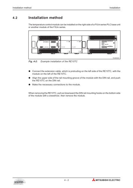
4.2 Installation method<br />
The temperature control module can be installed on the right side of a FX2N series PLC base unit<br />
or another module of the FX2N series.<br />
S/S 0V X0 X2 X4 X6 X10 X12 X14 X16<br />
24V X1 X3 X5 X7 X11 X13 X15 X17<br />
0 1 2 3 4 5 6 7<br />
IN<br />
10 11 12 13 14 15 16 17<br />
0 1 2 3 4 5 6 7<br />
OUT<br />
FX2N-32MT-DSS 10 11 12 13 14 15 16 17<br />
Y0 Y2 Y4 Y6 Y10 Y12 Y14 Y16<br />
+V1 Y1 Y3 +V1 Y5 Y7 +V2 Y11 Y13 +V3 Y15 Y17<br />
POWER<br />
RUN<br />
BATT.V<br />
PROG-E<br />
CPU-E<br />
FX2N-4AD POWER<br />
24 V<br />
A/D<br />
FX2N-4AD Fig. 4-2: Example installation of the <strong>RE10TC</strong><br />
� Connect the extension cable, which is protruding on the left side of the <strong>RE10TC</strong>, with the<br />
module on the left of the <strong>RE10TC</strong>.<br />
� Align the upper side of the rail mounting groove of the module with the DIN rail, and push<br />
the <strong>RE10TC</strong> on the DIN rail.<br />
� Make the necessary connections to the module.<br />
When removing the <strong>RE10TC</strong>, pull out downward the DIN rail mounting hooks on the bottom side<br />
of the module with a srewdriver, then remove the module.<br />
POWER<br />
24 V<br />
A/D<br />
+24V GND<br />
TC0+ TC1+ TC2+ TC3+ TC4+ TC5+ TC6+ TC7+ TC8+ TC9+ CT+ URT+ IRT+ AGND<br />
TC0- TC1- TC2- TC3- TC4- TC5- TC6- TC7- TC8- TC9- CT- URT- IRT-<br />
<strong>RE10TC</strong><br />
Heating Output Cooling Output<br />
8 9 0<br />
8 9 0<br />
Cooling Output Y - Output<br />
+24VY COM YH0 YH1 YH2 YH3 YH4 YH5 YH6 YH7 YH8 YH9 Y0 Y1 +12V VPP<br />
YC0 YC1 YC2 YC3 YC4 YC5 YC6 YC7 YC8 YC9 Y2 Y3 GND GND<br />
4-2 MITSUBISHI ELECTRIC<br />
2<br />
Loop<br />
POWER<br />
TC00002C