RE10TC Temperature Control Module Operating manual
RE10TC Temperature Control Module Operating manual
RE10TC Temperature Control Module Operating manual

You also want an ePaper? Increase the reach of your titles
YUMPU automatically turns print PDFs into web optimized ePapers that Google loves.
PID control Programming<br />
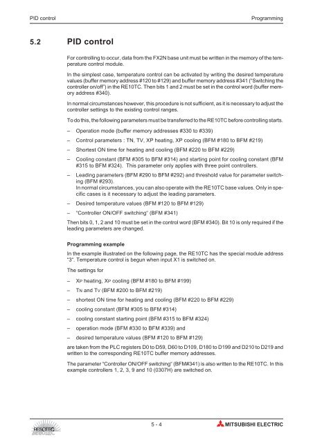
5.2 PID control<br />
For controlling to occur, data from the FX2N base unit must be written in the memory of the temperature<br />
control module.<br />
In the simplest case, temperature control can be activated by writing the desired temperature<br />
values (buffer memory address #120 to #129) and buffer memory address #341 (“Switching the<br />
controller on/off”) in the <strong>RE10TC</strong>. Then bits 1 and 2 must be set in the control word (buffer memory<br />
address #340).<br />
In normal circumstances however, this procedure is not sufficient, as it is necessary to adjust the<br />
controller settings to the existing control ranges.<br />
To do this, the following parameters must be transferred to the <strong>RE10TC</strong> before controlling starts.<br />
– Operation mode (buffer memory addresses #330 to #339)<br />
– <strong>Control</strong> parameters : TN, TV, XP heating, XP cooling (BFM #180 to BFM #219)<br />
– Shortest ON time for heating and cooling (BFM #220 to BFM #229)<br />
– Cooling constant (BFM #305 to BFM #314) and starting point for cooling constant (BFM<br />
#315 to BFM #324). This parameter only applies with three point controllers.<br />
– Leading parameters (BFM #290 to BFM #292) and threshold value for parameter switching<br />
(BFM #293).<br />
In normal circumstances, you can also operate with the <strong>RE10TC</strong> base values. Only in specific<br />
cases is it necessary to adjust the leading parameters.<br />
– Desired temperature values (BFM #120 to BFM #129)<br />
– “<strong>Control</strong>ler ON/OFF switching“ (BFM #341)<br />
Then bits 0, 1, 2 and 10 must be set in the control word (BFM #340). Bit 10 is only required if the<br />
leading parameters are changed.<br />
Programming example<br />
In the example illustrated on the following page, the <strong>RE10TC</strong> has the special module address<br />
“3“. <strong>Temperature</strong> control is begun when input X1 is switched on.<br />
The settings for<br />
– XP heating, XP cooling (BFM #180 to BFM #199)<br />
– TN and TV (BFM #200 to BFM #219)<br />
– shortest ON time for heating and cooling (BFM #220 to BFM #229)<br />
– cooling constant (BFM #305 to BFM #314)<br />
– cooling constant starting point (BFM #315 to BFM #324)<br />
– operation mode (BFM #330 to BFM #339) and<br />
– desired temperature values (BFM #120 to BFM #129)<br />
are taken from the PLC registers D0 to D59, D60 to D109, D180 to D199 and D210 to D219 and<br />
written to the corresponding <strong>RE10TC</strong> buffer memory addresses.<br />
The parameter “<strong>Control</strong>ler ON/OFF switching“ (BFM#341) is also written to the <strong>RE10TC</strong>. In this<br />
example controllers 1, 2, 3, 9 and 10 (0307H) are switched on.<br />
5-4 MITSUBISHI ELECTRIC