Thermostatic mixing valve Aquamix Series 61C ... - Watts Industries
Thermostatic mixing valve Aquamix Series 61C ... - Watts Industries
Thermostatic mixing valve Aquamix Series 61C ... - Watts Industries

You also want an ePaper? Increase the reach of your titles
YUMPU automatically turns print PDFs into web optimized ePapers that Google loves.
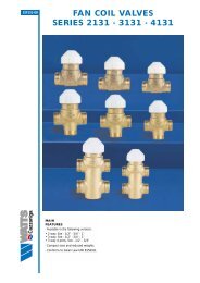
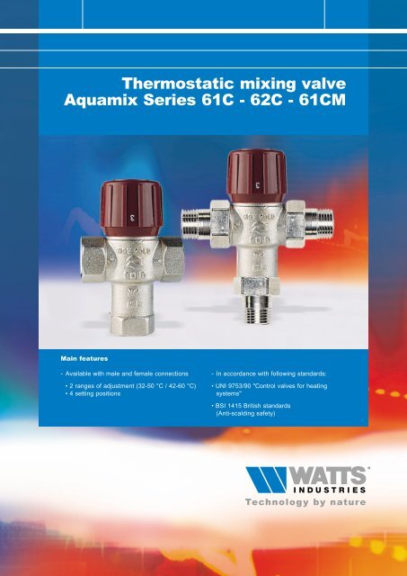
<strong>Thermostatic</strong> <strong>mixing</strong> <strong>valve</strong><br />
<strong>Aquamix</strong> <strong>Series</strong> <strong>61C</strong> - 62C - <strong>61C</strong>M<br />
Main features<br />
- Available with male and female connections<br />
• 2 ranges of adjustment (32-50 °C / 42-60 °C)<br />
• 4 setting positions<br />
- In accordance with following standards:<br />
• UNI 9753/90 "Control <strong>valve</strong>s for heating<br />
systems"<br />
• BSI 1415 British standards<br />
(Anti-scalding safety)
2<br />
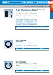
Description<br />
THERMOSTATIC MIXING VALVES AQUAMIX<br />
The thermostatic <strong>mixing</strong> <strong>valve</strong>s <strong>Aquamix</strong> <strong>Series</strong> <strong>61C</strong>, 62C and <strong>61C</strong>M are offered in versions with male and<br />
female connections as well as 4 setting positions. The <strong>valve</strong> body is made of brass nichel-plated on both inside<br />
and outside; moreover an inner teflon coating is provided in order to reduce scaling caused by hard water.<br />
Each <strong>valve</strong> is provided with two mesh strainers which, when inserted inside the hot water (+) and cold water (-)<br />
ports avoid depositing of coarse particles thereby protecting <strong>valve</strong> operation.<br />
Application<br />
The <strong>Aquamix</strong> <strong>valve</strong>s are used in domestic hot water distribution mains in order to keep a constant temperature of<br />
the mixed water against variation in the temperature of the hot water coming from the water heater, in accordance<br />
with Italian Decree DPR 412/93 which specifies the compulsory requirement to distribute domestic hot water with a<br />
maximum temperature of 48 °C (tolerance + 5 °C). The setting ranges of <strong>valve</strong>s <strong>Series</strong> <strong>61C</strong>, 62C and <strong>61C</strong>M allow<br />
direct <strong>mixing</strong> of hot water produced in the water heater (instantaneous or storage type) with cold water from the water<br />
main (to the water user at 36 - 38 °C) or obtaining higher values when used as premixer (42 - 50 °C) with consequent<br />
final <strong>mixing</strong> at the domestic water taps.<br />
Operation<br />
<strong>61C</strong><br />
AQUAMIX.<br />
<strong>Thermostatic</strong> <strong>mixing</strong> <strong>valve</strong> with 4 set positions. Anti-scald protection.<br />
Setting range: 32°C ÷ 50°C. Max. differential pressure: 2 bar. Female connections.<br />
Without internal check <strong>valve</strong>s.<br />
Type Part No. Size body Kvs Weight (g)<br />
<strong>61C</strong> 6109C12 1/2"F 1.5 630<br />
<strong>61C</strong> 6110C34 3/4"F 1.9 550<br />
<strong>61C</strong> 6111C1 1"F 2.1 650<br />
<strong>61C</strong>M<br />
62C<br />
Technical features<br />
Max. temperature, primary circuit 100 °C<br />
Max. operating pressure 10 bar<br />
Max. differential pressure 2 bar<br />
N° of setting positions 4<br />
Anti-scald safety BSI 1415<br />
Liquids which can be used Water<br />
AQUAMIX.<br />
<strong>Thermostatic</strong> <strong>mixing</strong> <strong>valve</strong> with 4 set positions. Anti-scald protection.<br />
Setting range: 32°C ÷ 50°C. Max. differential pressure: 2 bar. Connections with male<br />
tailpieces. Without internal check <strong>valve</strong>s.<br />
Type Part No. Size body Kvs Weight (g)<br />
<strong>61C</strong>M <strong>61C</strong>M12 1/2"M 1.5 710<br />
<strong>61C</strong>M <strong>61C</strong>M34 3/4"M 1.9 640<br />
<strong>61C</strong>M <strong>61C</strong>M1 1"M 2.1 730<br />
AQUAMIX<br />
<strong>Thermostatic</strong> <strong>mixing</strong> <strong>valve</strong> with 4 set positions. Anti-scald protection.<br />
Setting range: 42°C ÷ 60°C. Max. differential pressure: 2 bar. Female connections.<br />
Without internal check <strong>valve</strong>s.<br />
Type Part No. Size body Kvs Weight (g)<br />
62C 6209C12 1/2"F 1.5 630<br />
62C 6210C34 3/4"F 1.9 550<br />
62C 6211C1 1"F 2.1 650<br />
Design features<br />
Valve body a)brass, chrome-plated on inside<br />
and outside<br />
b)internally coated with scale-preventing<br />
teflon<br />
<strong>Thermostatic</strong> element Based on expansion of solid element<br />
Springs Stainless steel<br />
Plug Brass<br />
Operation is automatic and takes place through a heat-sensitive element inserted in the <strong>valve</strong> body which, upon<br />
coming into contact with the mixed water, either expands or contracts, thus regulating the inlet, with proportional<br />
action, of hot and cold water from the side ports in relation to the set value. If there is accidental failure of the cold
THERMOSTATIC MIXING VALVES AQUAMIX<br />
water, the <strong>valve</strong> is provided with a thermal stop device which promptly intervenes to close the disc in order to prevent<br />
hot water from entering. Thus it is not possible to emit unmixed water with consequent risk of scalds, and therefore<br />
the <strong>valve</strong> meets requirements of the British Standards. See chart for the hydraulic characteristics of flow rate and<br />
pressure drops of the <strong>valve</strong>s.<br />
Setting<br />
The <strong>valve</strong> setting, i.e. setting of the temperature of<br />
the mixed water, is performed by manually turning<br />
the graduated handwheel so that the number<br />
printed on the handwheel coincides with the<br />
reference mark embossed on the <strong>valve</strong> body. The<br />
numbers printed on the handwheel correspond to<br />
the temperatures indicated in (Table 1). The<br />
<strong>valve</strong> is factory-set by using hot water at 70 °C<br />
and mains water at 15 °C. Variation in<br />
temperature of the water in the primary circuit<br />
causes a deviation (* 2 °C) to the set values<br />
(Table 2). Likewise a variation in pressure<br />
Installation<br />
Choice of the thermostatic <strong>mixing</strong> <strong>valve</strong>s <strong>Aquamix</strong><br />
<strong>Series</strong> <strong>61C</strong>, 62C and <strong>61C</strong>M depends on the SIZE<br />
of the connecting piping. The <strong>valve</strong> can be installed<br />
on iron pipes (<strong>Series</strong> <strong>61C</strong> and 62C), copper and<br />
plastic pipes (<strong>Series</strong> <strong>61C</strong>M) in any position<br />
(vertical or horizontal). The <strong>valve</strong>s are designed for<br />
periodic maintenance of the internal components in<br />
order to remove any scaling without use of solvents<br />
and without scratching the metal surfaces. The<br />
three ways should be shut off before maintenance.<br />
This type of maintenance could be avoided by<br />
installing a water softener before the hot water inlet.<br />
Tab. 1<br />
Type 1 2 3 4<br />
<strong>61C</strong>-<strong>61C</strong>M 32° 38° 44° 50°<br />
62C<br />
Tab. 2<br />
42° 48° 54° 60°<br />
Water, primary circuit Setting positions<br />
°C 1 2 3 4<br />
50 30 36 42 48<br />
60 31 37 43 49<br />
70 32 38 44 50<br />
80 33 39 45 51<br />
90 34 40 46 52<br />
between P1 and P2 (See installation diagrams) exceeding 2 bar could cause dif-ferences; hence it is<br />
recommended to provide the circuit with a balancing <strong>valve</strong> (STAND type) at the cold water inlet port so as to create<br />
the same drop in pressure as occurs when the water flows through the heat exchanger. In order to prevent tampering,<br />
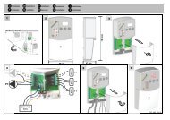
the handwheel can be locked in the required setting position as shown in Pictures 1-2-3. The reliability of the<br />
thermostatic <strong>mixing</strong> <strong>valve</strong>s <strong>Aquamix</strong> <strong>Series</strong> <strong>61C</strong>, 62C and <strong>61C</strong>M is ensured by 100% testing of the production.<br />
Pic. 1 Remove the label using<br />
a screw driver.<br />
Pic. 2 Back-off the stop<br />
screw and lift out the<br />
handwheel being careful not<br />
to turn the control rod.<br />
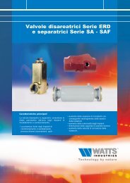
Installation diagrams, <strong>Aquamix</strong> <strong>valve</strong><br />
1) Setting <strong>valve</strong>, STAND series<br />
2) Check <strong>valve</strong><br />
3) <strong>Aquamix</strong> <strong>valve</strong>, <strong>61C</strong> - 62C <strong>Series</strong><br />
4) Safety <strong>valve</strong>, MSL <strong>Series</strong><br />
2<br />
4<br />
Pic. 3 Refit the handwheel so<br />
that the V reference corresponds<br />
to the embossed mark on the<br />
<strong>valve</strong> body. The handwheel is<br />
locked in this position.<br />
3<br />
1<br />
5<br />
Features<br />
1) Setting hand-wheel<br />
2) Hot water inlet port (+)<br />
3) <strong>Thermostatic</strong> element<br />
4) Mixed water outlet port (mix)<br />
5) Cold water inlet port (-)<br />
Pic. 4 Using a 28 mm openended<br />
spanner, unscrew the<br />
<strong>valve</strong> cover and take out the<br />
thermostatic element - spring -<br />
disc assembly. Clean with<br />
water, then reassemble.<br />
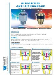
Domestic water systems with recirculation Water heat for domestic use<br />
P2<br />
4<br />
3<br />
1<br />
P1<br />
2<br />
2<br />
1) Water heater<br />
2) Safety and check <strong>valve</strong><br />
3) <strong>Aquamix</strong> <strong>valve</strong>.<br />
2<br />
1<br />
3<br />
3
4<br />
Re-order no. 69-0039-UK-IT/1-06-01-Rev.1<br />
THERMOSTATIC MIXING VALVES AQUAMIX<br />
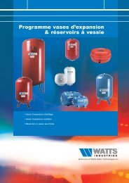
Overall dimensions (mm)<br />
<strong>61C</strong>/62C<br />
B<br />
C<br />
DN A B C Ø<br />
1/2" 70 107 52 45<br />
3/4" 70 107 52 45<br />
1" 80 110 52 45<br />
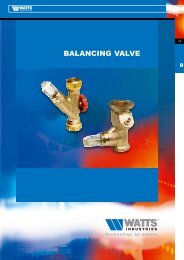
Flow rate/pressure drop charts<br />
<strong>61C</strong> - 62C - <strong>61C</strong>M<br />
PRESSURE DROPS<br />
[ kPa ]<br />
20<br />
10<br />
8<br />
5<br />
4<br />
3<br />
2<br />
1<br />
0.8<br />
0.5<br />
0.3<br />
0.2<br />
Ø<br />
A<br />
Size 3/4" Kvs 1.9<br />
Size 1/2" Kvs 1.5<br />
0.1<br />
1<br />
10 20 30 50 100 200 300 500 1000 2000 3000 [ l/h ]<br />
0.01 0.02 0.03 0.05 0.1 0.2 0.3 0.5 1 2 3<br />
FLOW RATE<br />
<strong>61C</strong>M<br />
Size 1" Kvs 2.1<br />
[ m bar ] [ mm w.g. ]<br />
3 [ m /h ]<br />
The descriptions and photographs contained in this product specification sheet are supplied by way of information only and are not binding.<br />
<strong>Watts</strong> <strong>Industries</strong> reserves the right to carry out any technical and design improvements to its products without prior notice.<br />
B<br />
DN A B C Ø<br />
1/2" 132 122 62 45<br />
3/4" 136 123 66 45<br />
1" 150 130 72 45<br />
200<br />
100<br />
80<br />
50<br />
40<br />
30<br />
20<br />
10<br />
5<br />
3<br />
2<br />
2000<br />
1000<br />
800<br />
500<br />
400<br />
300<br />
<strong>Watts</strong> <strong>Industries</strong> Italia S.r.l.<br />
Via Brenno, 21 - 20046 Biassono (MI), Italy<br />
Ph. : +39 039 49.86.1 - Fax : +39 039 49.86.222<br />
e-mail : info@wattsindustries.it<br />
www.wattsindustries.com<br />
200<br />
100<br />
50<br />
30<br />
20<br />
10<br />
D<br />
A<br />
C