Safety relay with additional on-delay UE 44-3 SL
Safety relay with additional on-delay UE 44-3 SL
Safety relay with additional on-delay UE 44-3 SL

You also want an ePaper? Increase the reach of your titles
YUMPU automatically turns print PDFs into web optimized ePapers that Google loves.
180 SAFETY CATALOG 2004<br />
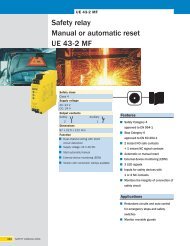
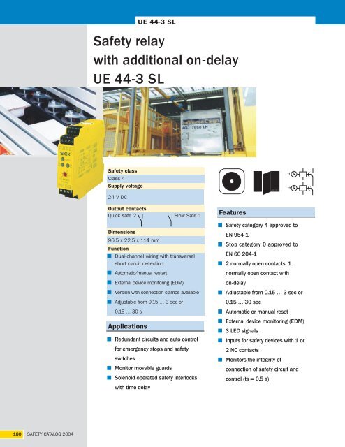
<strong>UE</strong> <strong>44</strong>-3 <strong>SL</strong><br />
<str<strong>on</strong>g>Safety</str<strong>on</strong>g> <str<strong>on</strong>g>relay</str<strong>on</strong>g><br />
<str<strong>on</strong>g>with</str<strong>on</strong>g> <str<strong>on</strong>g>additi<strong>on</strong>al</str<strong>on</strong>g> <strong>on</strong>-<strong>delay</strong><br />
<strong>UE</strong> <strong>44</strong>-3 <strong>SL</strong><br />
<str<strong>on</strong>g>Safety</str<strong>on</strong>g> class<br />
Class 4<br />
Supply voltage<br />
24 V DC<br />
Output c<strong>on</strong>tacts<br />
Quick safe 2 Slow Safe 1<br />
Dimensi<strong>on</strong>s<br />
96.5 x 22.5 x 114 mm<br />
Functi<strong>on</strong><br />
Dual-channel wiring <str<strong>on</strong>g>with</str<strong>on</strong>g> transversal<br />
short circuit detecti<strong>on</strong><br />
Automatic/manual restart<br />
External device m<strong>on</strong>itoring (EDM)<br />
Versi<strong>on</strong> <str<strong>on</strong>g>with</str<strong>on</strong>g> c<strong>on</strong>necti<strong>on</strong> clamps available<br />
Adjustable from 0.15 … 3 sec or<br />
0.15 … 30 s<br />
Applicati<strong>on</strong>s<br />
Redundant circuits and auto c<strong>on</strong>trol<br />
for emergency stops and safety<br />
switches<br />
M<strong>on</strong>itor movable guards<br />
Solenoid operated safety interlocks<br />
<str<strong>on</strong>g>with</str<strong>on</strong>g> time <strong>delay</strong><br />
Features<br />
<str<strong>on</strong>g>Safety</str<strong>on</strong>g> category 4 approved to<br />
EN 954-1<br />
Stop category 0 approved to<br />
EN 60 204-1<br />
2 normally open c<strong>on</strong>tacts, 1<br />
normally open c<strong>on</strong>tact <str<strong>on</strong>g>with</str<strong>on</strong>g><br />
<strong>on</strong>-<strong>delay</strong><br />
Adjustable from 0.15 … 3 sec or<br />
0.15 … 30 sec<br />
Automatic or manual reset<br />
External device m<strong>on</strong>itoring (EDM)<br />
3 LED signals<br />
Inputs for safety devices <str<strong>on</strong>g>with</str<strong>on</strong>g> 1 or<br />
2 NC c<strong>on</strong>tacts<br />
M<strong>on</strong>itors the integrity of<br />
c<strong>on</strong>necti<strong>on</strong> of safety circuit and<br />
c<strong>on</strong>trol (ts = 0.5 s)
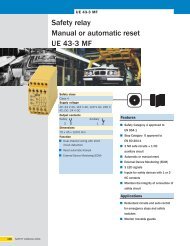
Dimensi<strong>on</strong>s<br />
107.6<br />
Functi<strong>on</strong>ality<br />
82.5<br />
93.3<br />
96.5<br />
After applying the supply voltage (LED SUPPLY illuminates), the normally open c<strong>on</strong>tacts<br />
(13 - 14 / 23 - 24) remain open. After completi<strong>on</strong> of the <strong>on</strong>-<strong>delay</strong> set <strong>on</strong> the <str<strong>on</strong>g>relay</str<strong>on</strong>g>, the<br />
<strong>delay</strong> circuit (37 - 38) closes, and the LED K3/K4 illuminates. If the c<strong>on</strong>nected sensor<br />
is not activated (i.e. the input circuits are closed), the normally open c<strong>on</strong>tacts (13 -<br />
14/23 - 24) close immediately during Automatic Reset, the LED K1/K2 illuminates,<br />
and the <strong>delay</strong> circuit (37 - 38) opens (LED K3/K4 off). In the case of Manual Reset,<br />
this <strong>on</strong>ly occurs after pressing and releasing the Reset butt<strong>on</strong>.<br />
The activati<strong>on</strong> of the sensor (opening of <strong>on</strong>e or both input circuits) affects the opening<br />
of both normally open c<strong>on</strong>tacts (13 - 14/23 - 24), <str<strong>on</strong>g>with</str<strong>on</strong>g> LEDs K1/K2 being off, and a<br />
time <strong>delay</strong>ed closing of the third circuit (37 - 38), <str<strong>on</strong>g>with</str<strong>on</strong>g> LED K3/K4 illuminating.<br />
External device m<strong>on</strong>itoring (EDM)<br />
The unit can take over external device m<strong>on</strong>itoring. The c<strong>on</strong>tactor m<strong>on</strong>itoring system<br />
m<strong>on</strong>itors the external <str<strong>on</strong>g>relay</str<strong>on</strong>g>s by way of their normally closed c<strong>on</strong>tacts.<br />
Manual reset<br />
For Manual resetting, a pushbutt<strong>on</strong> is to be c<strong>on</strong>nected between 24 V DC supply and<br />
terminal S34. This Reset is m<strong>on</strong>itored. For applicati<strong>on</strong>s <str<strong>on</strong>g>with</str<strong>on</strong>g> mechanical locking safety<br />
switches, <strong>on</strong>ly channel 2 must be closed during Manual Reset.<br />
Automatic reset<br />
For Automatic resetting S12 - S35 must be linked. For applicati<strong>on</strong>s <str<strong>on</strong>g>with</str<strong>on</strong>g> mechanical<br />
locking safety switches, <strong>on</strong>ly channel 1 must be closed during Automatic Reset.<br />
Cross circuit detecti<strong>on</strong><br />
Cross circuit is detected <strong>on</strong> dual-channel wired systems, if these are wired <str<strong>on</strong>g>with</str<strong>on</strong>g><br />
opposing polarity.<br />
M<strong>on</strong>itoring of synchr<strong>on</strong>izati<strong>on</strong><br />
If input 2 closes no later than 0.5 sec after input 1, the output circuits close. If input 2<br />
closes before input 1, the m<strong>on</strong>itoring of synchr<strong>on</strong>izati<strong>on</strong> will not be effected, and the<br />
output circuits will close. This m<strong>on</strong>itoring <strong>on</strong>ly takes place in Automatic Reset.<br />
The <strong>UE</strong> <strong>44</strong>-3 <strong>SL</strong> 2 unit has screw type terminals.<br />
The <strong>UE</strong> <strong>44</strong>-3 <strong>SL</strong> 3 unit has removable terminals.<br />
63<br />
75.3<br />
93.6<br />
114<br />
48.3<br />
66.7<br />
22.5<br />
SAFETY CATALOG 2004<br />
<strong>UE</strong> <strong>44</strong>-3 <strong>SL</strong><br />
<str<strong>on</strong>g>Safety</str<strong>on</strong>g> Relays<br />
181
182 SAFETY CATALOG 2004<br />
<strong>UE</strong> <strong>44</strong>-3 <strong>SL</strong><br />
General data descripti<strong>on</strong><br />
Supply voltage to A1/A2<br />
min. typ. max.<br />
Electrical output circuit > 25 V AC/60 V DC PELV<br />
Electrical output circuit < 25 V AC/60 V DC PELV or SELV<br />
<str<strong>on</strong>g>Safety</str<strong>on</strong>g> category: EN 954-1 4<br />
Supply voltage VS 20.4 V DC 24 V DC 26.4 V DC<br />
Power c<strong>on</strong>sumpti<strong>on</strong> 1.8 W<br />
Residual ripple in DC mode (<str<strong>on</strong>g>with</str<strong>on</strong>g>in the limits of VS)<br />
C<strong>on</strong>trol voltage S11- S33 and S21<br />
2.4 VPP<br />
C<strong>on</strong>trol voltage 22 V DC<br />
C<strong>on</strong>trol current 60 mA<br />
Electrical short circuit between S11 and A2 2200 mA<br />
Fuse PTC resistor<br />
Reacti<strong>on</strong> time by cross c<strong>on</strong>necti<strong>on</strong> 2 sec<br />
Galvanic separati<strong>on</strong> between A1/A2 and S11/S21<br />
Input circuits (S12 and S31)<br />
no<br />
Input current at S12 and S31 25 mA 100 mA<br />
Input current at S34/S35 (reset circuit)<br />
Reset time<br />
40 mA 50 mA<br />
Manual (S34) 30 ms<br />
Automatic (S35) 750 ms<br />
Synchr<strong>on</strong>izati<strong>on</strong> time 500 ms<br />
Activati<strong>on</strong> time for Reset butt<strong>on</strong> 250 ms<br />
Line resistance at the input circuit<br />
Output circuits (13 - 14, 23 - 24, 37 - 38)<br />
< 85 Ohm<br />
Resp<strong>on</strong>se time (K1/K2)<br />
Off-<strong>delay</strong> time (K3/K4)<br />
25 ms<br />
<strong>UE</strong> <strong>44</strong>-3 <strong>SL</strong> x D3 3 0.15 sec 3 sec<br />
<strong>UE</strong> <strong>44</strong>-3 <strong>SL</strong> x D3 30<br />
Relay c<strong>on</strong>tacts<br />
1.5 sec 30 sec<br />
C<strong>on</strong>tact type<br />
2 normally open c<strong>on</strong>tacts (NO), sfty. category 4<br />
1 normally open c<strong>on</strong>tact (NO), <strong>on</strong>-<strong>delay</strong>ed, sfty. category 3<br />
positively guided<br />
C<strong>on</strong>tact material<br />
Load capacity of c<strong>on</strong>tacts<br />
Silver alloy; gold-plated<br />
Switching voltage 10 V AC/DC 230 V AC/30 V DC<br />
Switching current 10mA 6 A<br />
Total current across all c<strong>on</strong>tacts 12 A<br />
Applicati<strong>on</strong> category to EN 60 947-5-1 AC-15 Ue 230 V AC, Ie 4 A (3600 c/h)<br />
DC-13 Ue 24 V DC, Ie 5 A (360 c/h)<br />
DC-13 Ue 24 V DC, Ie 3 A (3600c/h)<br />
Permitted switching frequency 3600 c/h<br />
Mechanical service life (switching cycles) 5 x 10⁶ Electrical service life (dependent up<strong>on</strong> loading) 2 x 10⁶ Operating data<br />
Surge voltage rating (Vimp) 4 kV<br />
Excess voltage category<br />
C<strong>on</strong>taminati<strong>on</strong> rating of the unit EN 50 178<br />
III<br />
External 3<br />
Internal 2<br />
Voltage rating 300 V AC<br />
Test voltage Veff (50 Hz) EN 60 439-1<br />
Protecti<strong>on</strong> type<br />
2 kV<br />
Housing IP 40<br />
Terminals IP 20<br />
Radio interference EN 60 947-1 02/99<br />
Interference emissi<strong>on</strong> according to EN 60 947-1 02/99<br />
Ambient operating temperature -25°C +55°C<br />
Storage temperature<br />
Cross secti<strong>on</strong>s of electrical c<strong>on</strong>ductors<br />
-25°C +75°C<br />
single strand wire (2x, identical cross secti<strong>on</strong>) 0.14 mm 2<br />
0.75 mm 2<br />
single strand wire (1x) 0.14 mm 2<br />
2.5 mm 2<br />
fine stranded wire <str<strong>on</strong>g>with</str<strong>on</strong>g> terminal crimps<br />
(2x, identical cross secti<strong>on</strong> 0.25 mm 2<br />
0.5 mm 2<br />
fine stranded wire <str<strong>on</strong>g>with</str<strong>on</strong>g> terminal crimps (1x) 0.25 mm 2<br />
2.5 mm 2<br />
Weight 0.2 Kg
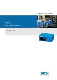
Internal circuitry<br />
C<strong>on</strong>necti<strong>on</strong> drawing<br />
Selecti<strong>on</strong> table<br />
Model Output<br />
C<strong>on</strong>necti<strong>on</strong> (terminal type) Supply voltage Delay in sec.<br />
Screw Removable 24 V DC<br />
Part number<br />
<strong>UE</strong> <strong>44</strong>- 3 <strong>SL</strong> 2 D3 3 6 024 907<br />
<strong>UE</strong> <strong>44</strong>- 3 <strong>SL</strong> 3 D3 3 6 024 908<br />
<strong>UE</strong> <strong>44</strong>- 3 <strong>SL</strong> 2 D3 30 6 024 909<br />
<strong>UE</strong> <strong>44</strong>- 3 <strong>SL</strong> 3 D3 30 6 024 910<br />
We recommend c<strong>on</strong>tacting Customer Service for product selecti<strong>on</strong><br />
SAFETY CATALOG 2004<br />
<strong>UE</strong> <strong>44</strong>-3 <strong>SL</strong><br />
<str<strong>on</strong>g>Safety</str<strong>on</strong>g> Relays<br />
183