
You also want an ePaper? Increase the reach of your titles
YUMPU automatically turns print PDFs into web optimized ePapers that Google loves.
©2006 <strong>Owen</strong> <strong>Oil</strong> <strong>Tools</strong><br />
All rights reserved<br />
Last Revised 11/2008<br />
<strong>Owen</strong> <strong>Oil</strong> <strong>Tools</strong><br />
Technical Manual<br />
E & B Select Fire Side Port<br />
Tandem Sub Assembly<br />
MAN-30-XXX-0002-96<br />
Caution<br />
Caution<br />
Saf Saf Safety Saf Safety<br />
ety Inf Inf Infor Inf Inf or orma or ma mation mation<br />
tion<br />
If you are not properly trained in the handling, and use of<br />
explosives devices, do not attempt the assembly of any<br />
<strong>Owen</strong> <strong>Oil</strong> <strong>Tools</strong> Perforating Systems or Firing Devices.<br />
Tec ec echnical<br />
ec hnical Assistance<br />
Assistance<br />
For technical assistance, please call<br />
or contact your local support station.
E E & & B B Select Select Fir Fire Fir e Side Side PP<br />
Por P or ort or<br />
Tandem andem Sub Sub Sub Assemb Assembly<br />
Assemb<br />
MAN-30-XXX-0002-96<br />
MAN-30-XXX-0002-96<br />
Revised 11/2008<br />
Blank page<br />
MAN-30-XXX-0002-96.2<br />
<strong>Owen</strong> <strong>Oil</strong> <strong>Tools</strong>
Revised 11/2008<br />
<strong>Owen</strong> <strong>Oil</strong> <strong>Tools</strong><br />
Description<br />
MAN-30-XXX-0002-96.3<br />
E E E & & B B Select Select Fir Fire Fir Fire<br />
e Side Side P PPor<br />
P or ort or<br />
Tandem andem Sub Sub Assemb Assembly<br />
Assemb<br />
MAN-30-XXX-0002-96<br />
MAN-30-XXX-0002-96<br />
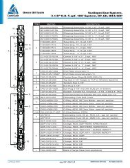
The E & B Select Fire Side Port Arming Sub and Switch Tandem Sub<br />
Assembly is used in wireline applications where a string of two or more<br />
perforating guns are detonated independently of each other.<br />
When the perforating gun is ready to be detonated, a DC current is<br />
applied which detonates the first or lowest gun in the string. The detonation<br />
from this gun activates the E & B switch for the next gun immediately<br />
above it. Applying an opposite polarity DC current will detonate<br />
the second gun and activate the E & B switch for the third gun. Alternating<br />
the polarity of DC current applied allows independent detonation of<br />
each perforating gun in the string.<br />
Features and Benefits<br />
• Allows independent detonation of multiple perforating guns in a<br />
multi-gun string.<br />
• Side port provides access to connect detonators and select fire<br />
switches.<br />
• Increased internal space for detonators and wiring.<br />
• Uses the same threads as standard tandem subs allowing for<br />
easy insertion into multi-gun strings.<br />
• Available in 73mm (2-7/8”), 79mm (3-1/8”), 86mm (3-3/8”), 101mm<br />
(4”) and 127mm (5”) sizes<br />
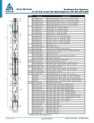
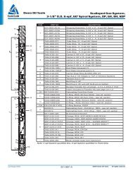
Size<br />
Nominal OD Pressure Rating<br />
73 mm 2.875 in 79 mm 2.875 in Same as Carrier<br />
79 mm 3.125 in 79 mm 2.875 in Same as Carrier<br />
86 mm 3.375 in 86 mm 3.375 in Same as Carrier<br />
101 mm 4.000 in 101 mm 4.000 in Same as Carrier<br />
127 mm 5.000 in 127 mm 5.000 in Same as Carrier
E E & & B B Select Select Fir Fire Fir e Side Side PP<br />
Por P or ort or<br />
Tandem andem Sub Sub Sub Assemb Assembly<br />
Assemb<br />
MAN-30-XXX-0002-96<br />
MAN-30-XXX-0002-96<br />
Revised 11/2008<br />
MAN-30-XXX-0002-96.4<br />
<strong>Owen</strong> <strong>Oil</strong> <strong>Tools</strong><br />
Item Part Number Qty Description<br />
-- 30-073-0002-96 --<br />
73m m E&B Select Fire Side Port Arming &<br />
Switch Tandem Sub Assembly<br />
1 30-073-0002-11 1 E&B Select Fire Arming Sub<br />
2 30-073-0002-12 1 E&B Select Fire Sw itch Sub<br />
3 30-000-0024-00 1 E&B Retainer Nut<br />
4 WT-401-0007-000 1 Top Fire Sub Cap, 1/2" Ratchet<br />
5 OOO-N569-216 1 O-Ring 90 Durometer Nitrile<br />
6 OOO-N569-223 1 O-Ring 90 Durometer Nitrile<br />
7 OOO-N569-228 2 O-Ring 90 Durometer Nitrile<br />
8 (A) Reference 1 DET-0000-010L, DET-3050-084 or DET-3051-021<br />
9 (A) (B) Reference 1 E&B Sw itch<br />
Item Part Number Qty Description<br />
-- 30-079-0002-96 --<br />
79m m E&B Select Fire Side Port Arming &<br />
Switch Tandem Sub Assembly<br />
1 30-079-0002-12 1 E&B Select Fire Arming Sub<br />
2 30-079-0002-13 1 E&B Select Fire Sw itch Sub<br />
3 30-000-0024-00 1 E&B Retainer Nut<br />
4 WT-401-0007-000 1 Top Fire Sub Cap, 1/2" Ratchet<br />
5 OOO-N569-216 1 O-Ring 90 Durometer Nitrile<br />
6 OOO-N569-223 1 O-Ring 90 Durometer Nitrile<br />
7 OOO-N569-230 2 O-Ring 90 Durometer Nitrile<br />
8 (A) Reference 1 DET-0000-010L, DET-3050-084 or DET-3051-021<br />
9 (A) (B) Reference 1 E&B Sw itch<br />
Item Part Number Qty Description<br />
-- 30-086-0002-96 --<br />
86m m E&B Select Fire Side Port Arming &<br />
Switch Tandem Sub Assembly<br />
1 30-086-0002-12 1 E&B Select Fire Arming Sub<br />
2 30-086-0002-13 1 E&B Select Fire Sw itch Sub<br />
3 30-000-0024-00 1 E&B Retainer Nut<br />
4 WT-401-0007-000 1 Top Fire Sub Cap, 1/2" Ratchet<br />
5 OOO-N569-216 1 O-Ring 90 Durometer Nitrile<br />
6 OOO-N569-223 1 O-Ring 90 Durometer Nitrile<br />
7 OOO-N569-231 2 O-Ring 90 Durometer Nitrile<br />
8 (A) Reference 1 DET-0000-010L, DET-3050-084 or DET-3051-021<br />
9 (A) (B) Reference 1 E&B Sw itch<br />
Item Part Number Qty Description<br />
-- 30-101-0002-96 --<br />
101mm E&B Select Fire Side Port Arming &<br />
Switch Tandem Sub Assembly<br />
1 30-101-0002-13 1 E&B Select Fire Arming Sub<br />
2 30-101-0002-14 1 E&B Select Fire Sw itch Sub<br />
3 30-000-0024-00 1 E&B Retainer Nut<br />
4 WT-401-0007-000 1 Top Fire Sub Cap, 1/2" Ratchet<br />
5 OOO-N569-216 1 O-Ring 90 Durometer Nitrile<br />
6 OOO-N569-223 1 O-Ring 90 Durometer Nitrile<br />
7 OOO-N569-236 2 O-Ring 90 Durometer Nitrile<br />
8 (A) Reference 1 DET-0000-010L, DET-3050-084 or DET-3051-021<br />
9 (A) (B) Reference 1 E&B Sw itch<br />
Item Part Number Qty Description<br />
-- 30-127-0002-96 --<br />
127mm E&B Select Fire Side Port Arming &<br />
Switch Tandem Sub Assembly<br />
1 30-127-0002-11 1 E&B Select Fire Arming Sub<br />
2 30-127-0002-12 1 E&B Select Fire Sw itch Sub<br />
3 30-000-0024-00 1 E&B Retainer Nut<br />
4 WT-401-0007-000 1 Top Fire Sub Cap, 1/2" Ratchet<br />
5 OOO-N569-216 1 O-Ring 90 Durometer Nitrile<br />
6 OOO-N569-223 1 O-Ring 90 Durometer Nitrile<br />
7 OOO-N569-346 2 O-Ring 90 Durometer Nitrile<br />
8 (A) Reference 1 DET-0000-010L, DET-3050-084 or DET-3051-021<br />
9 (A) (B) Reference 1 E&B Sw itch<br />
(A) Not Included in Assembly<br />
(B) Comes in both positive (P-100ST) and negative<br />
(N-100ST) polarity
Revised 11/2008<br />
<strong>Owen</strong> <strong>Oil</strong> <strong>Tools</strong><br />
MAN-30-XXX-0002-96.5<br />
E E E & & B B Select Select Fir Fire Fir Fire<br />
e Side Side P PPor<br />
P or ort or<br />
Tandem andem Sub Sub Assemb Assembly<br />
Assemb<br />
MAN-30-XXX-0002-96<br />
MAN-30-XXX-0002-96<br />
E & B Select Fire Switch Functionality<br />
Until the E & B Switch is activated, any current applied to the yellow<br />
wire (item X) will flow flow through the switch to the pin (item Z). In<br />
this state, there is an open circuit between the two yellow wires going<br />
into the switch (items X & Y), therefore, no current will pass through<br />
the detonator. When the gun directly below the sub is fired, the<br />
pressure and velocity from the detonation forces the pin (item Z) up<br />
into the switch closing the circuit between the two yellow wires (items<br />
X & Y). The diode (item W) allows current to pass through it in one<br />
direction only. In the P-100ST, the diode allows positive current to<br />
flow from the yellow wire to the red wire, whereas in the N-100ST the<br />
diode allows negative current to flow from the yellow wire to the black*<br />
wire. To fire a gun equipped with an activated P-100ST switch, a<br />
positive DC (direct current) must be applied. However, applying an<br />
AC (alternating current) will fire all guns in rapid succession.<br />
The first or bottom gun must be fired with the opposite polarity as the<br />
switch above it or the bottom two guns will fire in rapid succession.<br />
We recommend you follow the O-P-E-N (Odd-Positive-Even-<br />
Negative) practice preached in select-fire operations for wireline.<br />
Following this practice will result in using an N-100ST E & B Switch<br />
in the lowest E & B Tandem Sub, thus allowing you to fire the bottom<br />
(or first) gun with a positive DC current and then the second gun with<br />
a negative DC current. Every switch in a string must have the opposite<br />
polarity of the switch above and below it, as any two swtiches next to<br />
each other with the same polarity will both fire in rapid succession.<br />
*To distinguish the polarity of the switches, the P-100ST (positive<br />
DC current) uses a red wire for item V and the N-100ST (negative DC<br />
current) uses a black wire for item V.
E E & & B B Select Select Fir Fire Fir e Side Side PP<br />
Por P or ort or<br />
Tandem andem Sub Sub Sub Assemb Assembly<br />
Assemb<br />
MAN-30-XXX-0002-96<br />
MAN-30-XXX-0002-96<br />
Revised 11/2008<br />
MAN-30-XXX-0002-96.6<br />
<strong>Owen</strong> <strong>Oil</strong> <strong>Tools</strong><br />
E & B Select Fire Switch Installation<br />
Begin loading by inspecting the E & B Select Fire Switch Sub<br />
(item 2) bores. The switch bore should be free of debris. Check<br />
passage for wires as well. The switch (item 9) should fit freely into<br />
the bore up to the O-rings.<br />
If not already assembled, grease the two O-rings (item 7) and<br />
install them onto the switch sub (item 2), then screw the arming<br />
sub onto the switch sub and shoulder them out.<br />
Unwind switch wires and feed them through the sub assembly.<br />
While holding slight tension on the wires to prevent slack, insert<br />
the switch body up to the O-rings. A light coat of grease on the<br />
body and O-rings will help sealing and switch removal. Gently<br />
push or tap the switch body into bore.<br />
Do Not hit or press on the brass pin. This will activate the switch<br />
(close circuit between the two yellow wires).<br />
Ensure that the switch wires do not become pinched behind the<br />
switch body. Install the retainer (item 3), to seat the switch fully<br />
into the bore. Pinched of twisted wires are the most common<br />
cause of problems.<br />
Pull the free ends of the wires out through the side port of the<br />
arming sub.
Revised 11/2008<br />
<strong>Owen</strong> <strong>Oil</strong> <strong>Tools</strong><br />
Wiring Wiring Instructions Instructions for for Multigun Multigun Strings<br />
Strings<br />
MAN-30-XXX-0002-96.7<br />
E E E & & B B Select Select Fir Fire Fir Fire<br />
e Side Side P PPor<br />
P or ort or<br />
Tandem andem Sub Sub Assemb Assembly<br />
Assemb<br />
MAN-30-XXX-0002-96<br />
MAN-30-XXX-0002-96<br />
Read all instructions carefully before beginning assembly of carriers. Steps 1 to 21 can be done in the shop. Arming of the<br />
carrier must be done at the well site.<br />
Load Load Car Carrier Car rier<br />
1. Load charges and detonating cord in the carriers to be used as per standard procedure. Ensure that enough detonating<br />
cord is run to allow it to extend down through the top bore of the E & B Arming Sub (E & B Select Fire Side Port Arming<br />
Sub) and out the side port.<br />
2. Run one yellow wire down through the middle of each gun with enough slack to allow it to extend down through the top<br />
bore of the E & B arming sub and out the side port. Note the top carrier will need to have a longer wire as this wire must<br />
extend up through the top sub and make the connection with the cable head.<br />
3. Ground one blue wire to the bottom end of the charge tube in each carrier (except the bottom carrier) and allow enough<br />
length for it to extend down through the top bore of the E & B arming sub and out the side port.<br />
String String String Assembly<br />
Assembly<br />
Top Carriers<br />
4. Starting at the top carrier feed the top end of the yellow wire sticking out of the carrier up through the top sub.<br />
5. Screw the top sub into the top carrier ensuring the yellow wire does not twist up in the top sub bore.<br />
6. Connect the yellow wire to the wireline top sub electrical connection assembly.<br />
7. Feed the yellow wire, blue wire and detonating cord coming out of the bottom of the carrier through the top bore of the<br />
E & B arming sub and out the side port. If you are running an even number of carriers then the top E & B switch sub should<br />
have a negative E & B switch (N-100ST). If you are running an odd number of carriers then the top E & B switch sub should<br />
have a positive E & B switch (P-100ST). This will ensure the lowest switch is an N-100ST.<br />
8. Screw the E & B arming and switch sub assembly into the bottom of the carrier ensuring the yellow wire, blue wire and<br />
detonating cord do not bind in the bore of the arming sub.<br />
9. Connect the yellow wire from the previous step to the plain yellow wire from the E & B switch and leave them sticking<br />
out of the side port.<br />
Inter Inter Intermedia<br />
Inter media mediate media te Car Carrier Car rier riers rier<br />
10. Remove the E & B switch retainer nut from the E & B switch sub previously installed and slide it onto the yellow wire from<br />
the top of the next carrier.<br />
11. Wrap this yellow wire around the pin on the E & B switch sticking out of the bottom of the E & B switch sub from the previous<br />
step and secure with tape.<br />
12. Re-install the E & B switch retainer nut that was removed in Step 10.<br />
13. Screw this carrier onto the bottom of the E & B switch sub from the previous step ensuring that the wire does not bind<br />
in the carrier.<br />
14. Feed the yellow wire, blue wire and detonating cord coming out of the bottom of the carrier through the top bore of the<br />
next E & B tandem sub and out the side port. Use a tandem sub with the opposite polarity E & B switch as the E & B<br />
switch directly above it in the string. If this instruction is not followed, both carriers will fire in rapid succession<br />
when the lower of these two carriers is fired.<br />
15. Screw the E & B arming and switch sub assembly into the bottom of the carrier ensuring the yellow wire, blue wire and<br />
detonating cord do not bind in the bore of the arming sub.<br />
16. Connect the yellow wire from the previous step to the plain yellow wire from the E & B switch and leave them sticking<br />
out of the side port.<br />
17. Repeat Steps 10 to 16 for additional intermediate carriers.
E E & & B B Select Select Fir Fire Fir e Side Side PP<br />
Por P or ort or<br />
Tandem andem Sub Sub Sub Assemb Assembly<br />
Assemb<br />
MAN-30-XXX-0002-96<br />
MAN-30-XXX-0002-96<br />
Bottom Bottom Car Carrier Car rier<br />
Revised 11/2008<br />
MAN-30-XXX-0002-96.8<br />
<strong>Owen</strong> <strong>Oil</strong> <strong>Tools</strong><br />
18. Remove the E & B switch retainer nut from the E & B switch sub from the previous step and slide it onto the yellow wire<br />
from the top of the next carrier.<br />
19. Wrap this yellow wire around the pin on the E & B switch sticking out of the bottom of the E & B switch sub from the<br />
previous step and secure with tape.<br />
20. Re-install the E & B switch retainer nut that was removed in Step 18.<br />
21. Screw this carrier onto the bottom of the E & B switch sub from the previous step ensuring that the wire does not bind<br />
in the carrier.<br />
Ar Arm Ar m Car Carrier Car rier<br />
The following steps must be done at the well site.<br />
Bottom Bottom Car Carrier Car rier<br />
22. Follow company procedure for checking fire.<br />
23. Use standard procedure to connect the detonator electrically before ballistically, such as the following:<br />
24. Insert the detonator into a safety chamber prior to wiring.<br />
25. Ground one wire from the detonator to the charge tube.<br />
26. Connect the other wire from the detonator to the yellow wire sticking out of the bottom of the carrier.<br />
27. Remove detonator from the safety chamber.<br />
28. Connect detonator to the end of the detonating cord sticking out the bottom of the carrier. See instructions for model of<br />
detonator used.<br />
29. Insert the detonator, wires and detonating cord into the bottom of the charge tube.<br />
30. Screw the bottom sub onto the bottom of the carrier.<br />
Intermediate Carriers<br />
31. Start at the lowest carrier and work your way up completing the following steps for each carrier.<br />
32. Use standard procedure to connect the detonator electrically before ballistically, such as the following.<br />
33. Insert the detonator into a safety chamber prior to wiring.<br />
34. Connect one wire from the detonator to the blue wire sticking out of the side port of the E & B arming sub.<br />
35. Connect the other wire from the detonator to the red (P-100ST E & B switch) or black (N-100ST E & B switch) wire<br />
sticking out of the side port of the E & B arming sub.<br />
36. Remove detonator from the safety chamber.<br />
37. Connect detonator to the end of the detonating cord sticking out of the side port of the E & B arming sub. See<br />
instructions for model of detonator used.<br />
38. Insert the detonataor, detonating cord and wires into the side port of the E & B arming sub and install the side port<br />
sub cap. Ensure wires do not get caught in the side port cap threads.<br />
39. Repeat steps 32 to 38 for all remaining E & B arming and switch sub assemblies.<br />
The multigun string of carriers is now ready to be run down hole and fired. NOTE: the first (bottom) carrier will fire with a<br />
positive DC current. Each subsequent carrier will fire with an opposite polarity DC charge as the previous one.
Revised 11/2008<br />
<strong>Owen</strong> <strong>Oil</strong> <strong>Tools</strong><br />
MAN-30-XXX-0002-96.9<br />
E E E & & B B Select Select Fir Fire Fir Fire<br />
e Side Side P PPor<br />
P or ort or<br />
Tandem andem Sub Sub Assemb Assembly<br />
Assemb<br />
MAN-30-XXX-0002-96<br />
MAN-30-XXX-0002-96<br />
Sequence Sequence of of Events Events for for Three Three Gun Gun String<br />
String<br />
Firing<br />
Firing<br />
In this example gun, two E & B switches are used in a three gun<br />
string to enable select firing of each gun. The bottom switch (C) is<br />
an N-100ST and the top switch (F) is a P-100ST. Since the bottom<br />
switch will pass a negative DC current to Detonator (D) when it is<br />
activated, the bottom gun (B) must be fired with a positive DC current.<br />
1. The Gun String is placed at the correct depth and the operator<br />
applies a positive DC current at the shooting panel to fire the<br />
first (bottom) gun.<br />
2. The current flows through the bottom detonator (A), the bottom<br />
gun (B) fires and as a result the pin on the first switch (C) is<br />
pushed up which activates the switch. As the diode on the first<br />
switch (C) blocks positive DC current, current does not reach<br />
the detonator (D) and the second gun (E) does not fire at this<br />
time.<br />
3. When the operator is ready to fire the second gun (E) a negative<br />
DC current must be applied at the shooting panel.<br />
4. The negative DC current is allowed to pass through the diode<br />
on the switch (C) and the detonator (D) detonates which fires<br />
the second gun (E). As a result, the pin on the second switch<br />
(F) is pushed up, this activates the switch. The diode on the<br />
second switch (F) blocks negative DC current, therefore current<br />
does not reach the detonator (G) and the third gun (H) does not<br />
fire at this time.<br />
5. When the operator is ready to fire the third gun (H) a positive<br />
DC current must be applied at the shooting panel.<br />
6. The positive DC current is allowed to pass through the diode<br />
on the switch (F) and the detonator (G) detonates which fires<br />
the third and last gun (H).