Lubricated Plug Valves - Global Supply Line
Lubricated Plug Valves - Global Supply Line
Lubricated Plug Valves - Global Supply Line

You also want an ePaper? Increase the reach of your titles
YUMPU automatically turns print PDFs into web optimized ePapers that Google loves.
AUSTRALIAN PIPELINE VALVE<br />
<strong>Lubricated</strong> <strong>Plug</strong> <strong>Valves</strong><br />
Facsimile:<br />
+61-(0)8-8285 0035<br />
Email:<br />
admin@australianpipelinevalve.com.au<br />
Website:<br />
www.australianpipelinevalve.com.au<br />
®<br />
© Australian Pipeline Valve 2011
page 2<br />
This page is deliberately left blank.
AUSTRALIAN PIPELINE VALVE<br />
<strong>Plug</strong> Valve Index<br />
page 3<br />
Contents<br />
Applicable Standards<br />
Overview / Materials<br />
<strong>Plug</strong> Valve pattern styles<br />
Firesafe Certificates<br />
Pressure Balanced <strong>Plug</strong> Valve<br />
<strong>Lubricated</strong> <strong>Plug</strong> <strong>Valves</strong> Standard Type<br />
Teflon Sleeved <strong>Plug</strong> <strong>Valves</strong><br />
Fully Teflon <strong>Line</strong>d <strong>Plug</strong> <strong>Valves</strong><br />
Twinseal <strong>Plug</strong> Valve, Double Block and Bleed<br />
Part Number System<br />
Liability / Technical Risk<br />
Page 4<br />
Page 5<br />
Page 6<br />
Page 7-8<br />
Page 9-19<br />
Page 21-24<br />
Page 25-26<br />
Page 27-28<br />
Page 29-31<br />
Page 32<br />
Page 33<br />
®
Applicable Standards<br />
ANSI - AMERICAN NATIONAL STANDARD INSTITUTE<br />
ANSI - B 46. 1 - Surface - Texture<br />
ANSI - B 2. 1 - Pipe - Threads<br />
ANSI - B 16. 5 - Pipe Flanges and Flanged Fittings<br />
ANSI - B 16. 10 - Face to face Dimensions of <strong>Valves</strong><br />
ANSI - B 36. 10M - Welded and Seamless Wrought - Steel Pipe<br />
ANSI - B 16. 25 - Buttwelding - Ends<br />
ANSI - B 16. 34 - Steel <strong>Valves</strong> - Flanged and Buttwelding Ends<br />
ANSI - B 31. 1 - Power - Piping<br />
ANSI - B 31. 3 - Chemical Plant and Petroleum - Refinery - Piping<br />
ANSI - B 31. 4 - Liquid Transportation System - For Liquid Petroleum Gas<br />
ANSI - B 31. 8 - Gas Transmission and Distribution Piping System<br />
API - AMERICAN PETROLEUM INSTITUTE<br />
API - 6A - Specification for Wellheads and Christmas Tree Equipment<br />
API - 6D - Specification for Pipeline <strong>Valves</strong><br />
API - 598 - Testing for <strong>Valves</strong><br />
API - 599 - Steel <strong>Plug</strong> <strong>Valves</strong> for refinery Use<br />
API - 6FA - Specification for Fire Test for <strong>Valves</strong><br />
API - 607 - Specification for Fire Test for <strong>Valves</strong><br />
BS - BRITISh STANDARD<br />
BS - 5353 - <strong>Plug</strong> <strong>Valves</strong> for the Petroleum and Petrochemical Industries<br />
BS - 5146 - Inspection and Test of Steel <strong>Valves</strong> for Petroleum Industries<br />
BS - 2080 - Face to Face, Centre to Face - End to End n Steel <strong>Valves</strong><br />
BS - 1504 - Specification for Steel Castings for Pressure Purposes<br />
BS - 6755 - Part. 1 - Testing of <strong>Valves</strong> -<br />
(Specify. for production pressure testing requirements)<br />
MSS - MANUFACTURING STANDARDISATION SOCIETY<br />
MSS - SP 6 - Standard Finish for Contact Face of Pipe Flanges<br />
MSS - SP 25 - Standard Marking System for <strong>Valves</strong><br />
MSS - SP 44 - Steel Pipe <strong>Line</strong> Flanges<br />
MSS - SP 45 - By Pass - and Drain Connection Standard<br />
MSS - SP 55 - Quality Standard for Steel Casting Visual Method<br />
MSS - SP 61 - Hydrostatic - Testing of Steel <strong>Valves</strong><br />
NACE - NATIONAL ASSOCIATION CORROSION ENGINEERS<br />
NACE - MR.01.75 - Sulfide Stress - Cracking - Resistant Metallic<br />
Materials for Oilfield Equipment<br />
page 4<br />
®
AUSTRALIAN PIPELINE VALVE<br />
<strong>Lubricated</strong> <strong>Plug</strong> <strong>Valves</strong><br />
Australian Pipeline Valve <strong>Plug</strong> <strong>Valves</strong> are<br />
manufactured to cover a wide range of<br />
applications.<br />
STANDARD<br />
• <strong>Lubricated</strong> Standard type <strong>Plug</strong> <strong>Valves</strong>.<br />
• <strong>Lubricated</strong> Inverted Taper Pressure<br />
Balanced High Performance <strong>Plug</strong> <strong>Valves</strong>.<br />
• Class 150 to 2500<br />
Materials<br />
All APV <strong>Valves</strong> Products are normally available in:<br />
A216 WCB, WCC OR ASTM A105N<br />
ASTM A352 LCB OR LCC<br />
NACE MR.01.75.<br />
ASTM A182 F316 - A351 CF8M<br />
SPECIAL<br />
page 5<br />
SPECIAL<br />
• Class 150-300 and 600 three ways<br />
Transflow Pattern <strong>Lubricated</strong> <strong>Plug</strong> <strong>Valves</strong>.<br />
• Class 150 four ways transflow Pattern<br />
<strong>Lubricated</strong> <strong>Plug</strong> <strong>Valves</strong>.<br />
• Class 150-300-600 Full Jacketed <strong>Lubricated</strong><br />
<strong>Plug</strong> <strong>Valves</strong>.<br />
• Standard Carbon Steel which are supplied in 0.22% Maximum Carbon content and specified for standard service at temperatures from - 20ºC<br />
up to + 232ºC (-20ºF + 450ºF). <strong>Plug</strong>s are normally in Carbon Steel, nitrided or hardened or ENP.<br />
• Low temperature service suitable from - 46ºC to + 232ºC (-50ºF% + 450ºF) - normally used for below zero temperatures to - 46ºC must have<br />
a minimum average charpy “V” notch impact strength a / 15 foot / Lb.<br />
• In natural gas is possible to encounter small amounts of Hydrogen Sulfides (H2S) which may cause corrosion.<br />
The phenomenon is normally known as “Hydrogen Sulfide Embrittlement” or “Sulfide Stress Cracking”.<br />
The absorption of Hydrogen from part of steel causes ductility which, when added to other elements of stress caused by the service itself, may<br />
cause failure of the forged or cast component. Steels with yield strengths above 621 Mpa (90,000 PSI) or with hardness over 22 rockwell (235<br />
Brinell) may be subject to “Sulfide Stress Cracking”.<br />
In Nace MR.01.75 all basic material components are properly treated in order to remain bellow the hardness of 22 rockwell. In such a case,<br />
plugs are electro nickel coated or hardened to prevent galling action.<br />
• A 18.12 stainless steel material which contains Molybdenum and suitable for service temperature from -232C to + 371ºC (- 450ºF to 700ºF).<br />
Normally used for valves for high temperature service or where high corrosion resistance is needed.<br />
• Trim in 13% Chr. - 316 - Monel, Stellite No. 6 (coating). Body in WC6, F51, CF8M etc.<br />
®
<strong>Plug</strong> Valve Pattern Styles<br />
Australian Pipeline Valve plug valves are available in three different patterns to meet the valve needs of most piping systems.<br />
SHORT paTTeRN<br />
Same face to face dimensions as<br />
gate valves<br />
RegULaR paTTeRN<br />
Offers the largest port opening in a<br />
trapezoidal configuration-close to a<br />
full pipe port area<br />
pLUg VaLVe eND CONFIgURaTIONS<br />
VeNTURI paTTeRN<br />
Has a smaller port than the other<br />
two patterns. It is lower in cost and<br />
flow contours maximise the hydraulic<br />
efficiency<br />
Australian Pipeline Valve plug valves are available with threaded, flanged, butt weld or flanged x butt weld ends. Flanges are provided<br />
in either raised face or ring joint ends.<br />
page 6<br />
THREADED FLANGED WELDING ENDS BUTTWELD X RF<br />
®
page 7<br />
FIRESAFE CERTIFIED API607 5 TH<br />
EDITION AND API6FA 3 RD EDITION<br />
DNV Witnessed<br />
Australian Pipeline Valve is one of<br />
the first brands in the world to<br />
achieve firesafe<br />
certification to the<br />
latest fifth edition of API607 as well<br />
as the latest edition of API6FA.<br />
®
page 8<br />
®
AUSTRALIAN PIPELINE VALVE<br />
Model SSCR<br />
<strong>Lubricated</strong> Steel <strong>Plug</strong> <strong>Valves</strong><br />
Pressure Balanced Inverted Style<br />
ANSI Class 150 to 2500<br />
FIRESAFE CERTIFIED API607 5 TH<br />
EDITION AND API6FA 3 RD EDITION<br />
Pressure balanced plug valves are used<br />
where pulsating or static high pressures<br />
are present.<br />
The benefit a dynamic pressure balanced<br />
inverted plug gives is that it ensures<br />
equalised pressure between the <strong>Plug</strong> and<br />
upper and lower body chambers.<br />
Pressure is balanced by two holes in the<br />
<strong>Plug</strong> which connect the <strong>Plug</strong> port with<br />
the lower and upper cavities.<br />
The hole in the upper end is provided<br />
with a check valve so the pressure is<br />
always equal to the large end cavity and<br />
it is always equal to or greater than the<br />
line pressure in the small end cavity.<br />
page 9<br />
Advantages:-<br />
• Ease of maintenance.<br />
• In the event of the plug locking up, it is<br />
possible to inject lubricant through the<br />
grease nipple with the valve in service.<br />
• Leak tightness of the operating system<br />
WRENCh OPERATED GEAR OPERATED<br />
®<br />
is assured by the provision of a check<br />
valve in the lubrication injection<br />
fitting. An additional check valve is<br />
installed into the lubrication duct.<br />
• Firesafe API6FA, API607.
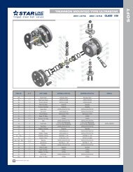
Steel <strong>Plug</strong> Valve Model SSCR<br />
Inverted <strong>Plug</strong>, Dynamic Pressure Balanced<br />
STEM PLUG COUPLING<br />
CHECK VALVE<br />
SEALANT FITTING<br />
LOWER BONNET<br />
BALANCING SPRINGS<br />
BEARINGS<br />
CAVITY<br />
This design may vary at any time without notice<br />
Bore Area Pressure Balanced<br />
STAINLESS STEEL STEM (BLOWOUT-PROOF)<br />
STOP PLATE AND INDICATOR<br />
SEAL<br />
STEM PACKING<br />
ISOLATED UPPER<br />
SEALANT CHAMBER<br />
TAPERED STEEL PLUG<br />
SEALS &<br />
GASKET<br />
PRESSURE RELEASE<br />
VALVE<br />
• A regular pattern provides an open area / port size of 80%. At least 60% for short pattern, at least 40% for venturi pattern.<br />
• For standard type port area see standard type section of this catalogue.<br />
page 10<br />
®
Model SSCR<br />
CLASS 150<br />
Pressure balanced, inverted plug<br />
Valve designed to API 6D and API 599<br />
Valve tested to API 6D and API 598<br />
Face to Face to API 6D and ANSI B16.10<br />
Flanged ends to ANSI B16.5<br />
Short Pattern<br />
Wrench Operated<br />
Short & Venturi Pattern<br />
Gear Operated<br />
page 11<br />
eNDS<br />
Threaded<br />
RF<br />
RTJ<br />
Butt Welded<br />
Socket Weld<br />
Size Inch 1<br />
L RF mm 165 178 190 203 229 267<br />
1 ⁄2 2 21 ⁄2 3 4 6<br />
DN mm 15 50 65 80 100 150<br />
L RJ mm - 191 203 216 242 280<br />
L BW mm - 267 305 330 356 457<br />
D mm 127 152 178 191 229 280<br />
F mm 120 130 150 170 190 235<br />
g mm 270 290 320 360 380 460<br />
J mm 40 45 50 50 50 65<br />
Weight (approx) Kg 15 20 30 40 60 110<br />
eNDS<br />
RF<br />
RTJ<br />
Butt Welded<br />
Socket Weld<br />
Size Inch 6 8 10 12 14 16 18 20 22 24 30<br />
DN mm 150 200 250 300 350 400 450 500 550 600 750<br />
L RF mm 267 292 330 356 686 762 864 914 1030 1067 1296<br />
L BW mm 457 521 559 635 686 762 864 914 1030 1067 1397<br />
D mm 280 343 406 483 534 597 635 699 750 813 984<br />
F mm 240 260 280 300 330 350 380 410 460 500 580<br />
g mm 480 510 530 550 600 620 640 700 750 800 900<br />
Handwheel dia. mm 500 500 650 650 650 650 650 650 800 800 800<br />
Weight (approx) Kg 135 170 230 350 460 700 880 1050 1500 2030 3000<br />
®
Model SSCR<br />
CLASS 300<br />
Pressure balanced, inverted plug<br />
Valve designed to API 6D and API 599<br />
Valve tested to API 6D and API 598<br />
Face to Face to API 6D and ANSI B16.10<br />
Flanged ends to ANSI B16.5<br />
Short Pattern<br />
Wrench Operated<br />
Venturi Pattern<br />
Gear Operated<br />
page 12<br />
eNDS<br />
Threaded<br />
RF<br />
RTJ<br />
Butt Welded<br />
Size Inch 1<br />
L RF mm 190 216 241 283 305 403<br />
1 ⁄2 2 21 ⁄2 3 4 6<br />
DN mm 15 50 65 80 100 150<br />
L RJ mm 203 232 257 299 321 419<br />
L BW mm - 267 305 330 356 457<br />
D mm 156 165 191 210 254 318<br />
F mm 115 140 150 170 180 235<br />
g mm 250 290 310 360 380 460<br />
J mm 40 45 50 50 50 65<br />
Weight (approx) Kg 20 25 35 50 76 140<br />
eNDS<br />
RF<br />
RTJ<br />
Butt Welded<br />
Size Inch 6 8 10 12 14 16 18 20 22 24<br />
DN mm 150 200 250 300 350 400 450 500 550 600<br />
L RF mm 403 419 457 502 762 838 914 991 1092 1143<br />
L RJ mm 419 435 473 518 778 854 930 1010 1114 1165<br />
L BW mm 457 521 559 635 762 838 914 991 1032 1143<br />
D mm 318 381 445 521 584 648 711 775 838 915<br />
F mm 240 260 280 300 350 370 400 430 480 530<br />
g mm 500 530 550 570 620 640 700 750 820 900<br />
Handwheel dia. mm 650 650 650 650 650 650 800 800 800 800<br />
Weight (approx) Kg 190 250 285 385 630 800 1000 1200 1500 2200<br />
®
MODEL SSCR<br />
CLASS 600<br />
Pressure balanced, inverted plug<br />
Valve designed to API 6D and API 599<br />
Valve tested to API 6D and API 598<br />
Face to Face to API 6D and ANSI B16.10<br />
Flanged ends to ANSI B16.5<br />
Regular Pattern<br />
Wrench Operated<br />
Regular & Venturi Pattern<br />
Gear Operated<br />
page 13<br />
eNDS<br />
RF<br />
RTJ<br />
Butt Weld<br />
Size Inch 1<br />
⁄2<br />
3<br />
⁄4 1 1 1 ⁄2 2 1 2 ⁄2 3 4<br />
DN mm 15 20 25 40 50 65 80 100<br />
L RF mm 159 191 216 241 292 330 356 432<br />
L RJ mm 159 191 216 241 295 333 359 435<br />
L BW mm - - 216 241 292 330 356 432<br />
D mm 95 118 121 156 165 191 210 273<br />
F mm 100 120 120 140 140 150 160 185<br />
g mm 22 27 27 40 45 50 50 50<br />
J mm 160 200 200 270 290 320 360 380<br />
Weight (approx) Kg 7 11 13 26 30 45 65 90<br />
eNDS<br />
RF<br />
RTJ<br />
Welded<br />
Size Inch 4 6 8 10 12 14 16 18 20 22 24<br />
DN mm 100 150 200 250 300 350 400 450 500 550 600<br />
L RF mm 432 559 660 787 838 889 991 1092 1194 1296 1397<br />
L RJ mm 435 562 663 790 841 892 994 1095 1200 1305 1407<br />
L BW mm 432 559 660 787 838 889 991 1092 1194 1296 1397<br />
D mm 273 356 419 508 559 603 686 743 813 870 940<br />
F mm 185 243 260 280 300 350 370 400 430 500 521<br />
g mm 380 520 550 570 580 610 625 700 750 830 900<br />
Handwheel dia. mm 500 500 650 650 650 650 650 800 800 800 800<br />
Weight (approx) Kg 135 210 390 550 680 860 1100 1550 2000 2500 3200<br />
®
MODEL SSCR<br />
CLASS 600<br />
Pressure balanced, inverted plug<br />
Valve designed to API 6D and API 599<br />
Valve tested to API 6D and API 598<br />
Face to Face to API 6D and ANSI B16.10<br />
Screwed ends to ANSI B 1.20.1<br />
Screwed or Socket Weld Ends<br />
Wrench Operated<br />
MODEL SSCR<br />
CLASS 800<br />
Screwed or Socket Weld Ends<br />
Wrench Operated<br />
page 14<br />
eNDS<br />
Threaded<br />
Socket Weld<br />
Size Inch 1<br />
⁄4<br />
3<br />
⁄8<br />
1<br />
⁄2<br />
3<br />
⁄4 1 1 1 ⁄2 2<br />
DN mm 8 10 15 20 25 40 50<br />
L mm 89 89 89<br />
⁄116 114 133<br />
⁄149<br />
187<br />
⁄175<br />
229<br />
⁄190<br />
F mm 90 90 95 95 100 118 132<br />
g mm 145 145 145 145 210 280 300<br />
J mm 22 22 22 22 27 40 45<br />
Weight (approx) Kg 4 4 5 5 9 17 26<br />
®
MODEL SSCR<br />
CLASS 900<br />
Pressure balanced, inverted plug<br />
Valve designed to API 6D and API 599<br />
Valve tested to API 6D and API 598<br />
Face to Face to API 6D and ANSI B16.10<br />
Flanged ends to ANSI B16.5<br />
Regular Pattern<br />
Wrench Operated<br />
Regular and Venturi Pattern<br />
Gear Operated<br />
page 15<br />
eNDS<br />
RF<br />
RTJ<br />
Butt Weld<br />
Size Inch 1<br />
⁄2<br />
3<br />
⁄4 1 1 1 ⁄2 2 3 4<br />
DN mm 15 20 25 40 50 80 100<br />
L RF mm 222 248 254 305 368 381 457<br />
L RJ mm 222 248 254 305 372 384 460<br />
L BW mm - - - - - 381 457<br />
D mm 121 130 149 178 216 241 292<br />
F mm 100 100 100 140 140 150 200<br />
g mm 150 180 200 280 300 360 380<br />
J mm 22 27 27 40 45 50 50<br />
Weight (approx) Kg 10 15 20 34 65 90 120<br />
eNDS<br />
RF<br />
RTJ<br />
Butt Weld<br />
Size Inch 4 6 8 10 12 14 16 20<br />
DN mm 100 150 200 250 300 350 400 500<br />
L RF mm 457 610 737 838 965 1028 1130 1321<br />
L RJ mm 460 613 740 841 968 1038 1140 1324<br />
L BW mm 452 610 737 838 965 1028 1130 1321<br />
D mm 292 381 470 546 610 641 705 857<br />
F mm 200 250 300 320 355 370 380 400<br />
g mm 410 510 540 580 660 660 680 700<br />
Handwheel dia. mm 500 600 650 650 800 800 800 800<br />
Weight (approx) Kg 145 320 480 760 1280 1500 1650 2500<br />
®
MODEL SSCR<br />
CLASS 1500<br />
Pressure balanced, inverted plug<br />
Valve designed to API 6D and API 599<br />
Valve tested to API 6D and API 598<br />
Face to Face to API 6D and ANSI B16.10<br />
Flanged ends to ANSI B16.5<br />
Regular Pattern<br />
Wrench Operated<br />
Regular and Venturi Pattern<br />
Gear Operated<br />
page 16<br />
eNDS<br />
RF<br />
RTJ<br />
Butt Weld<br />
Size Inch 1<br />
⁄2<br />
3<br />
⁄4 1 1 1 ⁄4<br />
1 1 ⁄2 2 1 2 ⁄2 3<br />
DN mm 15 20 25 32 40 50 65 80<br />
L RF mm 222 248 254 279 305 368 419 470<br />
L RJ mm 222 248 254 279 305 371 422 473<br />
L BW mm - - - - - - - 470<br />
D mm 121 130 149 159 178 216 245 267<br />
F mm 100 100 100 120 130 150 160 170<br />
g mm 160 200 200 250 270 390 320 360<br />
J mm 22 27 27 35 40 45 50 50<br />
Weight (approx) Kg 11 15 20 24 36 55 80 100<br />
eNDS<br />
RF<br />
RTJ<br />
Butt Weld<br />
Size Inch 3 4 6 8 10 12<br />
DN mm 80 100 50 200 250 300<br />
L RF mm 470 546 705 832 991 1130<br />
L RJ mm 473 549 711 842 1001 1146<br />
L BW mm 470 546 705 832 991 1130<br />
D mm 267 311 394 483 584 673<br />
F mm 150 210 260 300 360 460<br />
g mm 390 400 500 540 580 650<br />
Handwheel Dia. mm 500 500 650 650 800 800<br />
Weight (approx) Kg 130 220 550 1100 1350 1900<br />
®
MODEL SSCR<br />
CLASS 1500<br />
Pressure balanced, inverted plug<br />
Valve designed to API 6D and API 599<br />
Valve tested to API 6D and API 598<br />
Face to Face to API 6D and ANSI B16.10<br />
Screwed ends to ANSI B 1.20.1<br />
Screwed or Socket Weld Ends<br />
Wrench Operated<br />
MODEL SSCR<br />
CLASS 2500<br />
Screwed or Socket Weld Ends<br />
Wrench Operated<br />
page 17<br />
eNDS<br />
Threaded<br />
Socket Weld<br />
Size Inch 3<br />
⁄8<br />
1<br />
⁄2<br />
3<br />
⁄4 1 1 1 ⁄2 2<br />
DN mm 10 15 20 25 40 50<br />
L mm 89 89 114 133 229 229<br />
F mm 95 95 95 100 125 135<br />
g mm 145 145 145 210 280 300<br />
J mm 22 22 22 27 40 45<br />
Weight (approx) Kg 5 5 5 9 21 30<br />
eNDS<br />
Threaded<br />
Socket Weld<br />
Size Inch 1<br />
⁄2<br />
3<br />
⁄4 1<br />
DN mm 15 20 25<br />
L mm 133 133 133<br />
H mm 150 150 150<br />
g mm 240 240 240<br />
J mm 32 32 32<br />
Weight (approx) Kg 16 18 18<br />
®
MODEL SSCR<br />
CLASS 2500<br />
Pressure balanced, inverted plug<br />
Valve designed to API 6D and API 599<br />
Valve tested to API 6D and API 598<br />
Face to Face to API 6D and ANSI B16.10<br />
Flanged ends to ANSI B16.5<br />
Regular Pattern<br />
Wrench Operated<br />
Regular Pattern<br />
Gear Operated<br />
page 18<br />
eNDS<br />
RF<br />
RTJ<br />
Butt Weld<br />
Size Inch 1 1<br />
L RF mm 308 384 451 508<br />
1 ⁄2 2 21 ⁄2<br />
DN mm 25 40 50 65<br />
L RJ mm 308 387 454 514<br />
L BW mm 308 384 451 508<br />
D mm 159 203 235 267<br />
F mm 150 165 175 190<br />
g mm 240 240 260 280<br />
J mm 32 45 50 50<br />
Weight (approx) Kg 32 68 85 110<br />
eNDS<br />
RF<br />
RTJ<br />
Butt Weld<br />
Size Inch 3 4 6 8<br />
DN mm 80 100 150 200<br />
L RF mm - 673 914 1022<br />
L RJ mm - 683 927 1038<br />
L BW mm 578 673 914 1022<br />
D mm 305 356 483 552<br />
F mm 200 220 260 310<br />
g mm 410 425 470 510<br />
Handwheel Dia. mm 500 650 800 800<br />
Weight (approx) Kg 165 230 660 1250<br />
®
MODEL SSCR<br />
API 6A 2000, 3000, 5000 PSI<br />
Valve designed to API 6A<br />
Valve tested to API 6A<br />
Dimensions to API 6A<br />
page 19<br />
2000pSI<br />
2 1 ⁄16 2 9 ⁄16 3 1 ⁄8 4 1 ⁄16<br />
(RTJ) L 295 333 359 435<br />
CENTRE TO TOP H 152 163 174 187<br />
FLANGE OUTSIDE DIMENSION D 165 190.5 210 273<br />
3000pSI<br />
(RTJ) L 371 422 384 460<br />
CENTRE TO TOP H 152 174 201 220<br />
FLANGE OUTSIDE DIMENSION D 216 244 241 292<br />
5000pSI<br />
(RTJ) L 371 - 473 549<br />
CENTRE TO TOP H 152 - 201 217<br />
FLANGE OUTSIDE DIMENSION D 216 - 267 311<br />
®
page 20<br />
This page is deliberately left blank.
AUSTRALIAN PIPELINE VALVE<br />
Model SAPM / SAPL<br />
<strong>Lubricated</strong> <strong>Plug</strong> <strong>Valves</strong> Standard Type<br />
STAINLESS, CARBON STEEL AND IRON<br />
125/150/300 CLASS FLANGED ENDS TO ANSI B16-5<br />
page 21<br />
Stud<br />
Gland<br />
Sealant channels<br />
Bonnet<br />
Gland stud<br />
Lubricant fitting<br />
Wrench<br />
Check valve<br />
Packing ring<br />
Gland packing<br />
Gasket<br />
Body<br />
<strong>Plug</strong><br />
®
Model SAPM / SAPL<br />
Standard Type <strong>Lubricated</strong> Steel <strong>Plug</strong> <strong>Valves</strong><br />
The standard style has the stem<br />
extended from the top of the valve.<br />
The valves have a bolted cover which<br />
retains the plug in case the gland is<br />
removed. The gland maintains the<br />
pressure in the cover and prevents any<br />
leakage through the stem as well as<br />
retaining the plug in position.<br />
page 22<br />
The gland supports the packing and acts<br />
as an anti-friction bearing to prevent<br />
stem packing rotation. <strong>Plug</strong> lubrication<br />
grease is injected through a nipple (fitted<br />
with a check valve). Greasing can be<br />
done when the valve is under pressure.<br />
The plug grooves avoid grease leakage<br />
into the line as during rotation each<br />
groove is isolated from the other<br />
grooves. The stem is provided with a<br />
open/closed position indicator.<br />
Locking device is optional.<br />
®
Model SAPM / SAPL<br />
Dimensions Regular & Short pattern plug valves standard type<br />
ANSI 150 screwed or socket ends wrench operated<br />
Size<br />
DN<br />
Regular Pattern ANSI 150* & 125* wrench operated<br />
Regular Pattern ANSI 150 & 125* gear operated<br />
Weight (approx) Kg 150 220 270 340<br />
* BS Table D, E, F also available<br />
page 23<br />
Inch<br />
mm<br />
1 ⁄2”<br />
15<br />
3 ⁄4”<br />
20<br />
L mm 90 95 110 130 135 165<br />
H mm 140 150 170 200 200 250<br />
B mm 50 50 60 65 65 80<br />
E mm 22 22 25 25 25 28<br />
<strong>Plug</strong> port area % 80 80 80 80 95 90<br />
Weight (approx) Kg 4 5 8 10 12 14<br />
Size<br />
DN<br />
Inch<br />
mm<br />
1 ⁄2”<br />
15<br />
3 ⁄4”<br />
20<br />
1”<br />
25<br />
D mm 89 98 108 118 127 152 178 191 229 254 280<br />
L Butt Welding mm - - - - - 216<br />
⁄267<br />
241<br />
⁄305<br />
283<br />
⁄330<br />
305<br />
⁄356 - 403<br />
⁄457<br />
L Flange Raised Face mm 130 130 140 150 165 200 220 241 300 350 394<br />
B mm 40 45 50 50 60 70 80 90 110 140 160<br />
H mm 150 165 170 180 210 250 280 300 340 390 420<br />
E mm 20 20 22 22 25 28 35 38 44 50 50<br />
<strong>Plug</strong> port area % 100 100 100 100 100 85 85 85 80 80 75<br />
Weight (approx) Kg 3 4 6 9 13 18 24 35 50 75 110<br />
Size<br />
DN<br />
Inch<br />
mm<br />
6”<br />
150<br />
D mm 280 343 406 483<br />
L Butt Welding mm 457 521 559 635<br />
L Flange Raised Face mm 394 457 533 610<br />
B mm 160 190 210 225<br />
H mm 520 560 570 585<br />
M mm 320 360 370 390<br />
N mm 120 150 150 170<br />
Handwheel Diameter mm 500 650 650 650<br />
<strong>Plug</strong> port area % 75 60 50 40<br />
1 1 ⁄4”<br />
32<br />
8”<br />
200<br />
1”<br />
25<br />
1 1 ⁄2”<br />
40<br />
2”<br />
50<br />
1 1 ⁄4”<br />
30<br />
2 1 ⁄2”<br />
65<br />
10”<br />
250<br />
3”<br />
80<br />
1 1 ⁄2”<br />
40<br />
4”<br />
100<br />
5”<br />
125<br />
12”<br />
300<br />
2”<br />
50<br />
®<br />
6”<br />
150
Model SAPM / SAPL<br />
Dimensions short pattern plug valves standard type<br />
Short Pattern ANSI 150 & 125 wrench operated<br />
Size<br />
DN<br />
Short Pattern ANSI 150 & 125 gear operated<br />
ANSI 300 screwed or socket ends wrench operated<br />
Short Pattern ANSI 300 wrench operated<br />
Short Pattern ANSI 300 gear operated<br />
page 24<br />
Inch<br />
mm<br />
1 1 ⁄2”<br />
40<br />
2”<br />
50<br />
D mm 127 152 178 191 229 280<br />
L Butt Welding mm - 216<br />
⁄267<br />
241<br />
⁄305<br />
283<br />
⁄330<br />
305<br />
⁄356<br />
405<br />
⁄457<br />
L Flanged Raised Face mm 165 178 190 203 229 267<br />
B mm 60 70 80 90 110 155<br />
H mm 210 250 280 300 340 420<br />
E mm 25 28 35 38 44 50<br />
<strong>Plug</strong> port area % 100 85 85 85 80 75<br />
Weight (approx) Kg 13 16 22 28 45 86<br />
Size<br />
DN<br />
Inch<br />
mm<br />
6”<br />
150<br />
D mm 280 343 406 483<br />
L Flanged Raised Face mm 267 292 330 356<br />
B mm 155 190 240 270<br />
H mm 510 540 590 620<br />
M mm 320 350 400 430<br />
N mm 120 120 150 150<br />
Handwheel diameter mm 500 500 650 650<br />
<strong>Plug</strong> port area % 75 60 50 40<br />
Weight (approx) Kg 110 150 215 295<br />
Size<br />
DN<br />
Inch<br />
mm<br />
1 ⁄2”<br />
40<br />
3 ⁄4”<br />
50<br />
L mm 90 95 110 130 135 165<br />
H mm 140 150 170 200 200 250<br />
B mm 50 50 60 65 65 80<br />
E mm 22 22 25 25 25 28<br />
<strong>Plug</strong> port area % 80 80 80 80 95 90<br />
Weight (approx) Kg 4 5 8 10 12 14<br />
Size<br />
DN<br />
Inch<br />
mm<br />
3 ⁄4”<br />
20<br />
1”<br />
25<br />
D mm 118 124 156 165 191 210 254 318<br />
L Butt Welding mm - - - 267 305 330 356 457<br />
L Flange Raised Face mm 140 159 190 216 241 283 305 403<br />
L mm 152 172 203 232 257 299 321 419<br />
B mm 50 60 60 70 80 90 115 160<br />
H mm 156 170 210 250 280 300 340 420<br />
N mm - - - - - - - -<br />
E mm 22 25 28 32 35 38 44 50<br />
<strong>Plug</strong> port area % 100 100 100 85 85 80 80 80<br />
Weight (approx) Kg 8 12 15 20 35 45 60 130<br />
Size<br />
DN<br />
Inch<br />
mm<br />
6”<br />
150<br />
D mm 318 381 445 521<br />
L Butt Welding mm 457 521 559 635<br />
L Flange Raised Face mm 403 419 457 502<br />
L Flange Ring Joint mm 419 435 473 518<br />
B mm 160 190 215 235<br />
H mm 510 550 570 585<br />
M mm 330 360 390 400<br />
N mm 120 150 150 170<br />
Handwheel diameter mm 500 650 650 650<br />
<strong>Plug</strong> port area % 80 65 50 40<br />
Weight (approx) Kg 170 250 300 400<br />
1 1 ⁄2”<br />
40<br />
8”<br />
200<br />
8”<br />
200<br />
2 1 ⁄2”<br />
65<br />
1”<br />
65<br />
2”<br />
50<br />
2 1 ⁄2”<br />
65<br />
3”<br />
80<br />
1 1 ⁄4”<br />
80<br />
10”<br />
250<br />
10”<br />
250<br />
3”<br />
80<br />
4”<br />
100<br />
1 1 ⁄2”<br />
40<br />
4”<br />
100<br />
12”<br />
300<br />
12”<br />
300<br />
6”<br />
150<br />
2”<br />
50<br />
6”<br />
150<br />
®
AUSTRALIAN PIPELINE VALVE<br />
Model APSL<br />
Teflon Sleeved <strong>Plug</strong> <strong>Valves</strong><br />
• Raised face dimensions for class-150 and class-300 as per ANSI B-16.5<br />
• Valve up to size 100mm are lever operated.<br />
• Valve size 150mm and above are supplied with Gear operator.<br />
• BS Table D, E, F, H also available.<br />
page 25<br />
Valve Size mm 15 20 25 40 50 80 100 150 200 250 300<br />
aNSI CLaSS - 150<br />
a<br />
108 117 127 165 178 203 229 267 292 330 356<br />
aNSI CLaSS - 300 140 152 165 190 216 283 305 403 419 457 -<br />
Screwed<br />
Socket Weld<br />
Butt Weld<br />
83 83 117 140 165 203 - - - - -<br />
B 100 105 110 130 130 160 180 250 280 320 390<br />
®
Model APSL<br />
Materials<br />
Adjusting bolts<br />
Bonnet<br />
Static eliminator<br />
Thrust collar<br />
Metal diaphragm<br />
PTFE diaphragm<br />
Seal ring<br />
<strong>Plug</strong><br />
Sleeve<br />
Body<br />
page 26<br />
Wetted Parts<br />
Body and plug 316ss Carbon Steel Ductile Iron Monel<br />
Alloy 20 Nickel<br />
Hastelloy<br />
Sleeve PTFE PTFE PTFE PTFE<br />
Non Wetted Parts<br />
Adjusting bolts 304SS 304SS 304SS 304SS<br />
Cover CF8 Carbon Steel Ductile Iron CF8<br />
Cover bolts 304SS Steel Steel 304SS<br />
Static eliminator 304SS 304SS 304SS 304SS<br />
Thrust collar 304SS 304SS 304SS 304SS<br />
Metal diaphragm 304SS 304SS 304SS Monel<br />
Formed diaphragm PTFE PTFE PTFE PTFE<br />
Wedge ring<br />
Glassfilled<br />
PTFE<br />
Available body and trim materials.<br />
Carbon Steel Alloy 20<br />
Ductile Iron Hastelloy B<br />
304L Hastelloy C<br />
316L Nickel<br />
304 Monel<br />
316<br />
Duplex<br />
Glassfilled<br />
PTFE<br />
Glassfilled<br />
PTFE<br />
Glassfilled<br />
PTFE<br />
®
AUSTRALIAN PIPELINE VALVE<br />
Model APFL<br />
Fully Teflon <strong>Line</strong>d <strong>Plug</strong> <strong>Valves</strong><br />
Maximum corrosion resistance and<br />
eliminates product contamination.<br />
Complete PTFE lining in the body<br />
and on the flange faces with PFA<br />
covered plug and PFA reverse lip<br />
diaphragm-type stem seal. Features<br />
include: self-adjusting stem seal; non<br />
lubricated; positive shutoff; in-line<br />
adjustment.<br />
Available <strong>Line</strong>rs<br />
page 27<br />
(ANSI Class 150) rated at 180 psi<br />
(1,240 kPa) @ 400°F, 285 psi<br />
(1963kPa) @ 100°F (ANSI Class<br />
300) rated at 300 psi (2,206 kPa) @<br />
400°F; 750psi (5,102 kPa) @ 100°F.<br />
Designation Description<br />
Max. Service<br />
Temperature<br />
pTFe Tetrafluoroethylene polymer 400°F (204°C)<br />
pFa Perfluoroalkoxy polymer 400°F (204°C)<br />
Fep Fluorinated ethylene propylene 300°F (149°C)<br />
eTFe Ethylene/tetrafluoroethlene copolymer 300°F (149°C)<br />
Silica filled epoxy 215°F (102°C)<br />
UHMWpe Ultra high molecular weight polyethylene 200°F (93°C)<br />
pp Polypropylene 185°F (85°C)<br />
pSZ Partially stabilised zirconia 662°F (350°C)<br />
®
MODEL ADFL<br />
Drawing & Dimensions<br />
page 28<br />
IMpeRIaL all dimensions in Inches<br />
F-F FØ F.T.<br />
P.C.D. NOH SOH C-H<br />
Size CLASS CLASS CLASS RFØ RFT CLASS CLASS CLASS CLASS<br />
150# 300# 150# 300# 150# 300# 150# 300# 150# 300# 150# 300# 150# 300#<br />
1<br />
⁄2 4.25 5.50 3.50 3.75 .47 .56 1.38 .06 2.38 2.63 4 4 .63 .63 2.92 2.92<br />
3<br />
⁄4 4.63 6.00 3.88 4.63 .5 .63 1.89 .06 2.75 3.25 4 4 .63 .75 2.92 2.92<br />
1 5.00 6.50 4.25 4.88 .63 .69 2.00 .12 3.13 3.50 4 4 .63 .75 3.25 3.25<br />
11 ⁄2 6.50 7.50 5.00 6.13 .75 .81 2.88 .12 3.88 4.50 4 4 .63 .88 3.75 3.75<br />
2 7.00 8.50 6.00 6.50 .82 .88 3.63 .12 4.75 5.00 4 8 .75 .75 4.50 4.50<br />
3 8.00 11.13 7.50 8.25 .97 1.13 4.75 .12 6.00 6.63 4 8 .75 .88 5.00 5.00<br />
4 9.00 12.00 9.00 10.00 1.16 1.25 6.19 .12 7.50 7.88 8 8 .75 .88 6.10 6.10<br />
6 10.50 15.88 11.00 12.50 1.16 1.40 8.13 .12 9.50 10.63 8 12 .88 .88 7.75 7.75<br />
MeTRIC all dimensions in Millimetre<br />
F-F FØ F.T.<br />
P.C.D. NOH SOH C-H<br />
Size CLASS CLASS CLASS RFØ RFT CLASS CLASS CLASS CLASS<br />
150# 300# 150# 300# 150# 300# 150# 300# 150# 300# 150# 300# 150# 300#<br />
15 108 139 89 95 12 14 35 1.5 60 67 4 4 16 16 74 74<br />
20 117 152 98 117 13 16 48 1.5 70 82 4 4 16 19 74 74<br />
25 127 165 108 124 16 17.5 51 3 79 89 4 4 16 19 82 82<br />
40 165 190 127 155 19 20.5 73 3 98 114 4 4 16 22 95 95<br />
50 178 215 152 165 21 22.3 92 3 120 127 4 8 19 19 114 114<br />
80 203 282 190 209 24 28.7 120 3 152 168 4 8 19 22 127 127<br />
100 228 305 229 254 29 31.7 157 3 190 200 8 8 19 22 155 155<br />
150 266 403 279 317 29 35 206 3 241 270 8 12 22 22 197 197<br />
LegeND<br />
F-F FACE TO FACE NOH NUMBER OF HOLES<br />
FØ FLANGE DIAMETER SOH SIZE OF HOLE<br />
F-T FLANGE THICKNESS C-H CENTRE OF FLANGE TO HEIGHT OF BODY<br />
RFO RAISED FACE DIAMTER<br />
RFT RAISED FACE THICKNESS<br />
p.C.D PITCH CIRCLE DIAMTER<br />
®
AUSTRALIAN PIPELINE VALVE<br />
Twinseal <strong>Plug</strong> Valve Non <strong>Lubricated</strong><br />
Double Block and Bleed<br />
PRODUCT STRUCTURAL FEATURES<br />
Used in various industries such as petroleum, chemical industry, chemical fertiliser, power<br />
industry etc. Class 150 - 1500LBS and working temperature of -29~180ºC.<br />
MAIN STRUCTURAL FEATURES<br />
1. The Twinseal valve has a rugged structure, reliable sealing, excellent performance and exact<br />
tolerances.<br />
2. Sealing rings around the valve plug provide the seal. It has a unique design incorporating<br />
machined and pressed sealing rings.<br />
3. Bi-directional, double block and bleed.<br />
OPERATION PRINCIPLE<br />
When the hand wheel is turned, the plug will rotate toward the closing direction for 90 degree<br />
turn closing, the plug will then be firmly seated after moving downward into its closing position.<br />
When the hand wheel is turned inversely, first of all the plug will move upward and the valve<br />
plug and valve seat will be separated till the valve plug is turned 90 degree driven by the plug<br />
and finally the bore of the plug will be in alignment with the channel of valve body.<br />
The advantage of this type of valve is during the opening and closing of the valve, the plug and<br />
valve seat are separated and there is no friction, thus the sealing face experiences no abrasion<br />
in the process, at the same time the soft seal is applied for sealing so that there will be no<br />
leakage in the process of closing.<br />
TEChNICAL SPECIFICATION<br />
Operator Handwheel, bevel gear, electric-actuated<br />
Design Standard API599, API6D<br />
Face to Face ASME B16.10<br />
Flange End ASME B16.5<br />
Test and Inspection API598, API6D<br />
PERFORMANCE SPECIFICATION<br />
CLaSS (Map) SHeLL TeST (Map) SeaTINg TeST SUITaBLe TeMp. SUITaBLe MeDIUM<br />
150 3.0 2.2<br />
300<br />
600<br />
7.5<br />
15.0<br />
5.5<br />
11.0<br />
≤180°C* Water oil and gas<br />
900<br />
* High / low temperature available<br />
22.5 16.5<br />
FEATURES<br />
Non-slam<br />
The operator is self locking so that line pressure cannot force the plug<br />
to rotate. This prevents slamming and risk of injury.<br />
Tight shut off<br />
When the valve is closed, the seating segments are wedged tightly<br />
between the plug and body metal to metal. The soft seat material is<br />
compressed into the recessed groove. The design does not require<br />
springs or pressure to effect a seal.<br />
Double block and bleed and zero leakage<br />
The Twinseal valve provides upstream and downstream seal in both<br />
directions and a bleed point is then provided between the two seats,<br />
to prove no leakage.<br />
page 29<br />
Zero-leakage<br />
The Twinseal meets the demands of frequent cycling and verifiable,<br />
reliable zero leakage with positive shut-off upstream and downstream.<br />
®<br />
Zero wear<br />
Twinseal valves provide positive shut-off with zero leakage.<br />
The design of the valve ensures that during opening and closing the<br />
seals are not in contact with the body. Only at the last stage of closing<br />
does the seal contact the body - and then the force is compression<br />
only.<br />
Every turn of the handwheel retracts the seals from the body.<br />
That means no wear to the seals and long life.<br />
Large port<br />
Twinseal valves have a nominal plug port of 60 - 70% thus effecting<br />
minimum pressure drop.
Twinseal <strong>Plug</strong> Valve<br />
MAIN PARTS MATERIALS<br />
page 30<br />
NO. paRT NaMe MaTeRIaL<br />
1 Lower Bonnet<br />
ASTM A216 - WCB<br />
ASTM A351 - CF8, CF8M, CF3, CF3M<br />
2 O-Ring NBR, PTFE, VITON<br />
3 Sealing Ring Viton, PTFE<br />
4 <strong>Plug</strong><br />
5 Body<br />
ASTM A182 - Gr. F6a, ASTM A182 -F22<br />
ASTM A351 - CF8, CF8M, CF3, CF3M<br />
ASTM A216 - WCB<br />
ASTM A351 - CF8, CF8M, CF3, CF3M<br />
6 Bolt ASTM A193 - B7, A320 - B8, A193 - B8M<br />
7 Nut ASTM A194 - 2H, A194 - 9, A194 - 8M<br />
8 Cover<br />
ASTM A216 - WCB<br />
ASTM A351 - CF8, CF8M, CF3, CF3M<br />
9 Packing Flexible graphite + stainless steel, PTFE<br />
10 Gland<br />
ASTM A216 - WCB<br />
ASTM A351 - CF8, CF8M, CF3, CF3M<br />
11 Handwheel ASTM A436 Gr. 60 - 40 - 18, A216 - WCB<br />
12 Yoke Nut ZQA 19 - 4<br />
13 Yoke Nut Bushing<br />
14 Yoke<br />
15 Stem<br />
16 Guiding Stud<br />
17 Pin<br />
18 Disc<br />
ASTM A216 - WCB<br />
ASTM A351 - CF8, CF8M, CF3, CF3M<br />
ASTM A216 - WCB<br />
ASTM A351 - CF8, CF8M, CF3, CF3M<br />
ASTM A182 - Gr. F6a, ASTM A182 - F22<br />
ASTM A351 - CF8, CF8M, CF3, CF3M<br />
ASTM A182 - Gr. F6a, ASTM A182 -F22<br />
ASTM A351 - CF8, CF8M, CF3, CF3M<br />
ASTM A182 - Gr. F6a, ASTM A182 - F22<br />
ASTM A351 - CF8, CF8M, CF3, CF3M<br />
ASTM A182 - Gr. F6a, ASTM A182 - F22<br />
ASTM A351 - CF8, CF8M, CF3, CF3M<br />
®
Twinseal <strong>Plug</strong> Valve<br />
Dimensions<br />
Size<br />
CLaSS 150LB<br />
page 31<br />
mm 15 20 25 32 40 50 65 80 100 125 150 200 250 300 350<br />
in<br />
1 ⁄2<br />
3 ⁄4 1 1 1 ⁄4 1 1 ⁄2 2 2 1 ⁄2 3 4 5 6 8 10 12 14<br />
L 108 117 127 140 165 178 190 203 229 254 267 292 330 305 381<br />
H 230 260 300 340 380 435 460 490 525 570 625 700 780 870 980<br />
W 120 140 140 180 200 220 260 280 300 340 400 450 450 500 500<br />
Weight (Kg) 10 12 18 25 29 34 39 50 65 95 135 210 275 350 605<br />
Size<br />
CLaSS 300LB<br />
mm 15 20 25 32 40 50 65 80 100 125 150 200 250 300 350<br />
in<br />
1 ⁄2<br />
3 ⁄4 1 1 1 ⁄4 1 1 ⁄2 2 2 1 ⁄2 3 4 5 6 8 10 12 14<br />
L 140 152 165 178 190 216 241 283 305 381 403 419 457 502 762<br />
H 230 260 300 340 380 435 460 490 525 570 625 700 780 870 980<br />
W 120 140 140 180 200 220 260 280 300 340 400 450 450 500 500<br />
Weight (Kg) 11 13 20 27 31 37 44 60 82 115 165 225 305 405 650<br />
Size<br />
CLaSS 600LB<br />
mm 15 20 25 32 40 50 65 80 100 125 150 200 250 300 350<br />
in<br />
1 ⁄2<br />
3 ⁄4 1 1 1 ⁄4 1 1 ⁄2 2 2 1 ⁄2 3 4 5 6 8 10 12 14<br />
L 165 190 216 229 241 292 330 356 432 508 559 660 787 838 889<br />
H 230 260 300 340 380 435 460 490 525 570 625 700 780 870 980<br />
W 120 140 140 180 200 220 260 280 300 340 400 450 450 500 500<br />
Weight (Kg) 13 15 22 29 34 41 54 68 99 128 191 258 430 650 870<br />
Size<br />
CLaSS 900LB<br />
mm 15 20 25 32 40 50 65 80 100 125 150 200 250 300 350<br />
in<br />
1 ⁄2<br />
3 ⁄4 1 1 1 ⁄4 1 1 ⁄2 2 2 1 ⁄2 3 4 5 6 8 10 12 14<br />
L 229 229 254 279 305 368 419 381 457 559 610 737 838 965 1029<br />
H 230 260 300 340 380 435 460 490 525 570 625 700 780 870 980<br />
W 120 140 140 180 200 220 260 280 300 340 400 450 450 500 500<br />
Weight (Kg) 15 19 24 32 38 47 62 75 115 147 220 379 490 720 1020<br />
®
Part Number System for <strong>Plug</strong> <strong>Valves</strong><br />
®<br />
S S C R - R H W 6 3 C e B N<br />
page 32<br />
10<br />
1 2 3 4 5 6 7 8 9<br />
Body Material<br />
7<br />
Pressure Class<br />
5<br />
Model Number<br />
1<br />
A Cast iron<br />
B Alloy steel (API6A)<br />
C Steel WCB / A105 (N)<br />
S Stainless CF8M/316<br />
T Stainless CF8/304<br />
Z Special<br />
<strong>Plug</strong> Material<br />
8<br />
1 125LB<br />
2 150LB<br />
3 300LB<br />
6 600LB<br />
8 800LB<br />
9 900LB<br />
A 1500LB<br />
B 2500LB<br />
C API 2000<br />
D API 3000<br />
E API 5000<br />
SSCR Steel body pressure balanced, inverted style, firesafe<br />
SAPM Steel body, standard type, taper style, firesafe<br />
SAPL Iron body, standard type, taper style<br />
SAPM Iron body, standard type, taper style, firesafe<br />
APBR Iron body, standard type, inverted style<br />
APMM Multiway 3 way L port<br />
APMN Multiway 3 way T port<br />
APMW Multiway 4 way<br />
APFL Steel or iron body, fully lined, taper style<br />
APSL Steel or iron body, sleeved, taper style<br />
TWIN Twinseal Double Block & Bleed<br />
N SG (nodular)<br />
C Case hardened carbon steel<br />
E Electroless nickel coated plug (.003")<br />
F Ni-hard coated plug (.003")<br />
G 316SS/CF8M<br />
H 304SS/CF8<br />
I CR13/F6<br />
J PTFE/PFA coated<br />
Z Special<br />
End Connection<br />
6<br />
Style<br />
3<br />
Pattern<br />
2<br />
Seat/Lining Type<br />
9<br />
H Pressure balanced<br />
S Standard type<br />
R Round Type<br />
Z Other<br />
R Regular<br />
S Short<br />
V Venturi<br />
Blank Multiway<br />
A Sleeved PTFE/PFA<br />
B Metal seat lubricated<br />
C Fully lined PTFE/PFA<br />
D Metal seat non lubricated<br />
Z Special<br />
Operator<br />
4<br />
Special Features<br />
10<br />
2 Screwed BSP taper<br />
3 ANSI flanged RF<br />
4 Screwed NPT (API5L)<br />
5 ANSI flanged RTJ<br />
6 Buttweld end<br />
7 Screwed BSP parallel<br />
8 ANSI uncut RTJ<br />
9 Socketweld female<br />
D Flanged BS table D<br />
F Flanged BS table F<br />
H Flanged BS table H<br />
K Flanged PN10 RF<br />
I Flanged PN16 RF<br />
J ANSI RF x Buttweld<br />
J Jacketed<br />
E Extended Stem<br />
J Electric operator<br />
W Wrench (bare stem)<br />
G Gear operated horizontal spindle<br />
LG Extension with gear<br />
LW Extension with wrench<br />
P Pneumatic operator<br />
N NACE
CONSIDERATIONS OF TECHNICAL RISK / LIMIT OF LIABILITY<br />
FOR AUSTRALIAN PIPELINE VALVE PLUG VALVES<br />
Australian Pipeline Valve don’t consider in our design the following factors of risk:<br />
1. Australian Pipeline Valve “Standard” plug valves can be used in a temperature range between -28.8/+250ºC. For<br />
service temperatures below -28.8ºC plug valve construction materials shall be submitted to an impact test at the<br />
minimum service temperature. For temperatures between -28.8ºC & +250ºC plug valves have to be provided<br />
with seals able to withstand the temperature degree required.<br />
2. The onus is on the customer to specify all materials of construction and service conditions. Australian Pipeline<br />
Valve shall assume standard materials and conditions if not otherwise specified.<br />
3. Australian Pipeline Valve “Standard” plug valves are not designed with special devices to withstand a sudden<br />
thermal jump (thermal shock).<br />
4. In general Australian Pipeline Valve “Standard” plug valves are not mechanically designed to bear overloads due<br />
to exceptional atmospheric or natural phenomenon’s (such as earthquakes).<br />
5. In general Australian Pipeline Valve “Standard” plug valves are not designed to bear loads on flanges, on pipe<br />
connections or pipeline.<br />
6. In general Australian Pipeline Valve “Standard” plug valves can’t withstand ice inside their bodies (in this case<br />
user has to consider the optional stem extension for insulating, avoiding the presence of residual product inside<br />
the valve).<br />
7. Australian Pipeline Valve “Standard” non lubricated plug valves are suitable for “industrial” oxygen (not medical)<br />
service when supplied degreased and packed in polyethylene bags only.<br />
8. The compatibility between plug valves construction materials and medium is selected by the user. The user is<br />
ultimately responsible for verifying the compatibility between medium and materials.<br />
9. Other special service applications like abrasive service, dirty service, high temperature service, low temperature<br />
service, vacuum service etc, need to be stated at quotation phase.<br />
PLUG VALVE START-UP<br />
Before installing the plug valve onto the pipe-line it is mandatory for the user to verify the compatibility of the plug valve<br />
with service conditions (medium, temperature and pressure). With reference to standard plug valves held in stock, the<br />
reseller and end user will have to assure themselves of the compatibility with the use of conditions required by the<br />
customer. Australian Pipeline Valve plug valves must be only used for on-off (fully open/fully closed) service.<br />
Before using the plug valve in a potential explosive atmosphere it’s necessary: -<br />
• To verify the compatibility between the plug valve and the zone in which the valve should be installed.<br />
• To foresee the pipe-line ground condition on which the plug valve should be installed.<br />
• To check that the temperature of the plug valve surface is not higher than the flammable point of the atmosphere<br />
in which the plug valve is installed (in this case specify an insulating cover device for the valve and an<br />
extension for the wrench)<br />
• Before installing plug valves with welding ends, make sure that the process of welding is carried out observing<br />
all the safety norms the classified zone requirements.<br />
• To avoid mechanical knocks during the installation that may cause sparks.<br />
Australian Pipeline Valve cannot be held responsible for damage caused by use of the product especially if it is improper<br />
use or modified.<br />
page 33<br />
®
®<br />
Q UALITY<br />
A SSURANCE<br />
Local Distributor<br />
CERTIFICATION<br />
As quality assurance requirements have grown in recent years we have continually improved<br />
our systems particularily in the field of material traceability. Full chemical and mechanical<br />
certificates can be supplied for all pressure retaining parts. In most cases we also provide it<br />
on all major trim components.<br />
We have endeavoured to provide a broad outline of our range and capabilities. Because we<br />
are continually developing new products for our customers the brochure will, to some extent be<br />
incomplete. This catalogue is a general overview only, individual drawings and data sheets<br />
relevant to valve supplies can be furnished on request. Therefore if you have any requirements<br />
in the field of valves please contact us for a prompt response. Continuous development of<br />
Australian Pipeline Valve products may necessitate changes in the design or manufacturing<br />
processes. Australian Pipeline Valve reserves the right to affect any such changes without<br />
prior notice.