Effect of Using Ferro-Cement on the Mechanical Properties of ...
Effect of Using Ferro-Cement on the Mechanical Properties of ...
Effect of Using Ferro-Cement on the Mechanical Properties of ...

Create successful ePaper yourself
Turn your PDF publications into a flip-book with our unique Google optimized e-Paper software.
13 th Internati<strong>on</strong>al C<strong>on</strong>ference <strong>on</strong><br />
AEROSPACE SCIENCES & AVIATION TECHNOLOGY,<br />
ASAT- 13, May 26 – 28, 2009, E-Mail: asat@mtc.edu.eg<br />
Military Technical College, Kobry Elkobbah, Cairo, Egypt<br />
Tel : +(202) 24025292 – 24036138, Fax: +(202) 22621908<br />
1/13<br />
Paper: ASAT-13-MS-24<br />
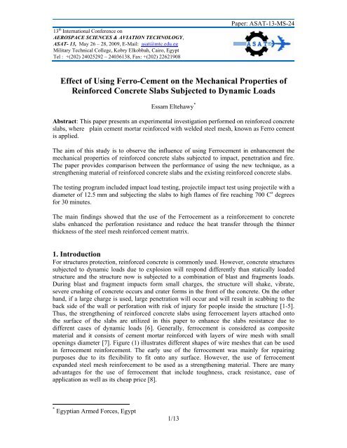
<str<strong>on</strong>g>Effect</str<strong>on</strong>g> <str<strong>on</strong>g>of</str<strong>on</strong>g> <str<strong>on</strong>g>Using</str<strong>on</strong>g> <str<strong>on</strong>g>Ferro</str<strong>on</strong>g>-<str<strong>on</strong>g>Cement</str<strong>on</strong>g> <strong>on</strong> <strong>the</strong> <strong>Mechanical</strong> <strong>Properties</strong> <str<strong>on</strong>g>of</str<strong>on</strong>g><br />
Reinforced C<strong>on</strong>crete Slabs Subjected to Dynamic Loads<br />
Essam Eltehawy *<br />
Abstract: This paper presents an experimental investigati<strong>on</strong> performed <strong>on</strong> reinforced c<strong>on</strong>crete<br />
slabs, where plain cement mortar reinforced with welded steel mesh, known as <str<strong>on</strong>g>Ferro</str<strong>on</strong>g> cement<br />
is applied.<br />
The aim <str<strong>on</strong>g>of</str<strong>on</strong>g> this study is to observe <strong>the</strong> influence <str<strong>on</strong>g>of</str<strong>on</strong>g> using <str<strong>on</strong>g>Ferro</str<strong>on</strong>g>cement in enhancement <strong>the</strong><br />
mechanical properties <str<strong>on</strong>g>of</str<strong>on</strong>g> reinforced c<strong>on</strong>crete slabs subjected to impact, penetrati<strong>on</strong> and fire.<br />
The paper provides comparis<strong>on</strong> between <strong>the</strong> performance <str<strong>on</strong>g>of</str<strong>on</strong>g> using <strong>the</strong> new technique, as a<br />
streng<strong>the</strong>ning material <str<strong>on</strong>g>of</str<strong>on</strong>g> reinforced c<strong>on</strong>crete slabs and <strong>the</strong> existing reinforced c<strong>on</strong>crete slabs.<br />
The testing program included impact load testing, projectile impact test using projectile with a<br />
diameter <str<strong>on</strong>g>of</str<strong>on</strong>g> 12.5 mm and subjecting <strong>the</strong> slabs to high flames <str<strong>on</strong>g>of</str<strong>on</strong>g> fire reaching 700 C o degrees<br />
for 30 minutes.<br />
The main findings showed that <strong>the</strong> use <str<strong>on</strong>g>of</str<strong>on</strong>g> <strong>the</strong> <str<strong>on</strong>g>Ferro</str<strong>on</strong>g>cement as a reinforcement to c<strong>on</strong>crete<br />
slabs enhanced <strong>the</strong> perforati<strong>on</strong> resistance and reduce <strong>the</strong> heat transfer through <strong>the</strong> thinner<br />
thickness <str<strong>on</strong>g>of</str<strong>on</strong>g> <strong>the</strong> steel mesh reinforced cement matrix.<br />
1. Introducti<strong>on</strong><br />
For structures protecti<strong>on</strong>, reinforced c<strong>on</strong>crete is comm<strong>on</strong>ly used. However, c<strong>on</strong>crete structures<br />
subjected to dynamic loads due to explosi<strong>on</strong> will resp<strong>on</strong>d differently than statically loaded<br />
structure and <strong>the</strong> structure now is subjected to a combinati<strong>on</strong> <str<strong>on</strong>g>of</str<strong>on</strong>g> blast and fragments loads.<br />
During blast and fragment impacts form small charges, <strong>the</strong> structure will shake, vibrate,<br />
severe crushing <str<strong>on</strong>g>of</str<strong>on</strong>g> c<strong>on</strong>crete occurs and crater forms in <strong>the</strong> fr<strong>on</strong>t <str<strong>on</strong>g>of</str<strong>on</strong>g> <strong>the</strong> c<strong>on</strong>crete. On <strong>the</strong> o<strong>the</strong>r<br />
hand, if a large charge is used, large penetrati<strong>on</strong> will occur and will result in scabbing to <strong>the</strong><br />
back side <str<strong>on</strong>g>of</str<strong>on</strong>g> <strong>the</strong> wall or perforati<strong>on</strong> with risk <str<strong>on</strong>g>of</str<strong>on</strong>g> injury for people inside <strong>the</strong> structure [1-5].<br />
Thus, <strong>the</strong> streng<strong>the</strong>ning <str<strong>on</strong>g>of</str<strong>on</strong>g> reinforced c<strong>on</strong>crete slabs using ferrocement layers attached <strong>on</strong>to<br />
<strong>the</strong> surface <str<strong>on</strong>g>of</str<strong>on</strong>g> <strong>the</strong> slabs are utilized in this paper to enhance <strong>the</strong> slabs resistance due to<br />
different cases <str<strong>on</strong>g>of</str<strong>on</strong>g> dynamic loads [6]. Generally, ferrocement is c<strong>on</strong>sidered as composite<br />
material and it c<strong>on</strong>sists <str<strong>on</strong>g>of</str<strong>on</strong>g> cement mortar reinforced with layers <str<strong>on</strong>g>of</str<strong>on</strong>g> wire mesh with small<br />
openings diameter [7]. Figure (1) illustrates different shapes <str<strong>on</strong>g>of</str<strong>on</strong>g> wire meshes that can be used<br />
in ferrocement reinforcement. The early use <str<strong>on</strong>g>of</str<strong>on</strong>g> <strong>the</strong> ferrocement was mainly for repairing<br />
purposes due to its flexibility to fit <strong>on</strong>to any surface. However, <strong>the</strong> use <str<strong>on</strong>g>of</str<strong>on</strong>g> ferrocement<br />
expanded steel mesh reinforcement to be used as a streng<strong>the</strong>ning material. There are many<br />
advantages for <strong>the</strong> use <str<strong>on</strong>g>of</str<strong>on</strong>g> ferrocement that include toughness, crack resistance, ease <str<strong>on</strong>g>of</str<strong>on</strong>g><br />
applicati<strong>on</strong> as well as its cheap price [8].<br />
* Egyptian Armed Forces, Egypt
Paper: ASAT-13-MS-24<br />
This paper mainly focuses <strong>on</strong> reducing <strong>the</strong> effect <str<strong>on</strong>g>of</str<strong>on</strong>g> direct weap<strong>on</strong>s <strong>on</strong> <strong>the</strong> c<strong>on</strong>crete structures.<br />
Generally speaking, weap<strong>on</strong> systems can be divided into c<strong>on</strong>venti<strong>on</strong>al weap<strong>on</strong>s, nuclear<br />
weap<strong>on</strong>s, biological weap<strong>on</strong>s and chemical weap<strong>on</strong>s. The main c<strong>on</strong>cern <str<strong>on</strong>g>of</str<strong>on</strong>g> this paper is to<br />
study <strong>the</strong> effect <str<strong>on</strong>g>of</str<strong>on</strong>g> c<strong>on</strong>venti<strong>on</strong>al weap<strong>on</strong>s attacks <strong>on</strong> reinforced c<strong>on</strong>crete structure especially<br />
those generating both blast waves and fragments [9]. The c<strong>on</strong>venti<strong>on</strong>al weap<strong>on</strong>s are divided<br />
into direct and indirect projectiles. The damage <str<strong>on</strong>g>of</str<strong>on</strong>g> direct projectile without explosive is<br />
caused by <strong>the</strong> mass and velocity <str<strong>on</strong>g>of</str<strong>on</strong>g> <strong>the</strong> projectile. For direct projectiles with explosive such as<br />
grenades, bombs, torpedoes, missiles, and reboots, <strong>the</strong> damage is caused not <strong>on</strong>ly by <strong>the</strong><br />
primary kinetic energy for <strong>the</strong> projectile but also by <strong>the</strong> shock wave due to <strong>the</strong> explosi<strong>on</strong>.<br />
Fur<strong>the</strong>rmore, fragments are produced from <strong>the</strong> projectile case, which will fly towards <strong>the</strong><br />
target.<br />
This paper is utilizing <strong>the</strong> technique <str<strong>on</strong>g>of</str<strong>on</strong>g> using ferrocement as a streng<strong>the</strong>ning and repair<br />
materials for existing reinforced c<strong>on</strong>crete slabs [10], which depends <strong>on</strong> experimental<br />
measurement <str<strong>on</strong>g>of</str<strong>on</strong>g> <strong>the</strong> depth <str<strong>on</strong>g>of</str<strong>on</strong>g> penetrati<strong>on</strong>. The depth <str<strong>on</strong>g>of</str<strong>on</strong>g> penetrati<strong>on</strong> is a functi<strong>on</strong> <str<strong>on</strong>g>of</str<strong>on</strong>g> <strong>the</strong> velocity<br />
and mass <str<strong>on</strong>g>of</str<strong>on</strong>g> <strong>the</strong> projectile as well as <strong>the</strong> stiffness <str<strong>on</strong>g>of</str<strong>on</strong>g> <strong>the</strong> targets material. For c<strong>on</strong>crete <strong>the</strong> latter<br />
parameter is normally related to <strong>the</strong> compressive strength [11-14]. Finally, <strong>the</strong> objective <str<strong>on</strong>g>of</str<strong>on</strong>g><br />
this paper is to determine <strong>the</strong> effect <str<strong>on</strong>g>of</str<strong>on</strong>g> using different numbers <str<strong>on</strong>g>of</str<strong>on</strong>g> layers <str<strong>on</strong>g>of</str<strong>on</strong>g> ferrocement <strong>on</strong> <strong>the</strong><br />
behavior <str<strong>on</strong>g>of</str<strong>on</strong>g> reinforced c<strong>on</strong>crete slabs subjected to dynamic loads that generates a combinati<strong>on</strong><br />
<str<strong>on</strong>g>of</str<strong>on</strong>g> blast wave and fragment impacts.<br />
Fig. (1) Different types <str<strong>on</strong>g>of</str<strong>on</strong>g> wire meshes used in ferrocement reinforcement.<br />
2. Experimental Program<br />
The experimental program is divided into different stages<br />
Specimens' Preparati<strong>on</strong><br />
<str<strong>on</strong>g>Ferro</str<strong>on</strong>g>cement slabs Tests<br />
Impact Penetrati<strong>on</strong><br />
Fire Fire & Penetrati<strong>on</strong><br />
2.1. Materials<br />
The c<strong>on</strong>crete was designed according to <strong>the</strong> American c<strong>on</strong>crete institute (ACI) method to give<br />
an average strength <str<strong>on</strong>g>of</str<strong>on</strong>g> 33.5 MPa after 28 days. Water/cement ratio was c<strong>on</strong>stant (W/C =<br />
0.45). <str<strong>on</strong>g>Cement</str<strong>on</strong>g>, used was ordinary Portland cement with a density <str<strong>on</strong>g>of</str<strong>on</strong>g> 3150 kg/m<br />
2/13<br />
3 and its<br />
nominal c<strong>on</strong>tent was 400 kg/m 3 . Fine aggregate was siliceous sand with a specific gravity <str<strong>on</strong>g>of</str<strong>on</strong>g>
3/13<br />
Paper: ASAT-13-MS-24<br />
2650 kg/m 3 . Coarse aggregate was crushed dolomite st<strong>on</strong>e <str<strong>on</strong>g>of</str<strong>on</strong>g> specific gravity 2550 kg/m 3 and<br />
with maximum particle size 6.3 mm, <strong>the</strong> mix proporti<strong>on</strong>s by weight for 1 m 3 <str<strong>on</strong>g>of</str<strong>on</strong>g> c<strong>on</strong>crete are<br />
shown in Table (1).<br />
Table (1) Mix proporti<strong>on</strong>s <str<strong>on</strong>g>of</str<strong>on</strong>g> c<strong>on</strong>crete.<br />
Material <str<strong>on</strong>g>Cement</str<strong>on</strong>g><br />
(kg)<br />
Sand<br />
(kg)<br />
Crushed dolomite<br />
(kg)<br />
Water<br />
(kg)<br />
Kg/m 3 400 918 918 180<br />
2.2. Specimen<br />
Two classes <str<strong>on</strong>g>of</str<strong>on</strong>g> target specimens were c<strong>on</strong>sidered, first c<strong>on</strong>trol slab specimens and <strong>the</strong> o<strong>the</strong>r<br />
was <str<strong>on</strong>g>Ferro</str<strong>on</strong>g>cement slab specimens, all specimens are square shaped with dimensi<strong>on</strong>s 55 x 55<br />
centimeter and <strong>the</strong> depth is different according to <strong>the</strong> number <str<strong>on</strong>g>of</str<strong>on</strong>g> layers.<br />
2.2.1. C<strong>on</strong>trol Specimens<br />
The c<strong>on</strong>trol slabs were mortar cement reinforced with hot rolled steel bars <str<strong>on</strong>g>of</str<strong>on</strong>g> diameter 10 mm<br />
in two perpendicular directi<strong>on</strong>s with spacing <str<strong>on</strong>g>of</str<strong>on</strong>g> 15 cm between <strong>the</strong> bars, and <strong>the</strong> total depth <str<strong>on</strong>g>of</str<strong>on</strong>g><br />
<strong>the</strong> slabs was 10 cm &14 cm, Fig. (2).<br />
2.2.2. <str<strong>on</strong>g>Ferro</str<strong>on</strong>g>cement Specimens<br />
<str<strong>on</strong>g>Ferro</str<strong>on</strong>g>cement slabs were mortar cement reinforced with different numbers <str<strong>on</strong>g>of</str<strong>on</strong>g> expanded metal<br />
sheet (style ½”- #16 from (LOUCON METAL LTD.), Fig. (3).<br />
Fig. (2) C<strong>on</strong>trol specimens' preparati<strong>on</strong>.
2.3. Tests Procedures<br />
Fig. (3) <str<strong>on</strong>g>Ferro</str<strong>on</strong>g>cement technique specimens' preparati<strong>on</strong>.<br />
4/13<br />
Paper: ASAT-13-MS-24<br />
2.3.1. Impact Test<br />
The following Table (2) presents <strong>the</strong> slabs that have been tested under impact load. The<br />
following slabs were tested at Carlet<strong>on</strong> University civil laboratory to measure <strong>the</strong> penetrati<strong>on</strong><br />
depth under drop impact load. The slabs were installed <strong>on</strong> <strong>the</strong> test facility and <strong>the</strong>y were tested<br />
by using a weight to stroke <strong>the</strong> slabs. The weight was dropped under its own weight which<br />
was 335.5kg. Figure (4) Shows <strong>the</strong> impact test.<br />
Table (2) Slabs to be tested under drop impact load.<br />
Slab Dimensi<strong>on</strong>(cm) Reinforcement C<strong>on</strong>crete dim. <str<strong>on</strong>g>Ferro</str<strong>on</strong>g>cement<br />
SI-1 55×55×10 4�10 D 55×55×10 ---------------<br />
SI-2 55×55×14 4�10 D 55×55×14 ---------------<br />
SI-3 55×55×14 4�10 D 55×55×10 2 layers U,D*<br />
SI-4 55×55×14 4�10 D 55×55×10 2 layers U,D**<br />
D = Down layer, U = Upper layer<br />
* 2 layers <str<strong>on</strong>g>of</str<strong>on</strong>g> ferrocement each layer c<strong>on</strong>tains 2 meshes<br />
** 2 layers <str<strong>on</strong>g>of</str<strong>on</strong>g> ferrocement each layer c<strong>on</strong>tains 4 meshes<br />
2.3.2. Penetrati<strong>on</strong> Test<br />
Table (3) presents <strong>the</strong> slabs which have been tested under penetrati<strong>on</strong> by means <str<strong>on</strong>g>of</str<strong>on</strong>g> gun shots.<br />
The following slabs were tested at CANMET explosives laboratories to measure <strong>the</strong><br />
penetrati<strong>on</strong> depth under gun shots. Four to five shots were executed <strong>on</strong> <strong>the</strong> following slabs,<br />
<strong>on</strong>e <strong>on</strong> each corner and <strong>on</strong>e in <strong>the</strong> center <strong>on</strong> <strong>the</strong> slabs. Figure (5) shows <strong>the</strong> penetrati<strong>on</strong> test.
Fig. (4) Impact Test<br />
Table (3) Slabs to be tested under penetrati<strong>on</strong>.<br />
5/13<br />
Paper: ASAT-13-MS-24<br />
Slab Dimensi<strong>on</strong>(cm) Reinforcement C<strong>on</strong>crete dim. <str<strong>on</strong>g>Ferro</str<strong>on</strong>g>cement<br />
SP-1 55×55×10 4�10 U,D 55×55×10 ---------------<br />
SP-2 55×55×14 4�10 U,D 55×55×14 ---------------<br />
SP-3 55×55×14 4�10 U,D 55×55×10 2 layers U,D*<br />
SP-4 55×55×14 4�10 U,D 55×55×10 2 layers U,D**<br />
U = .Upper layer, D = Down layer<br />
*. … 2 layers <str<strong>on</strong>g>of</str<strong>on</strong>g> ferrocement each layer c<strong>on</strong>tains 2 meshes<br />
** …2 layers <str<strong>on</strong>g>of</str<strong>on</strong>g> ferrocement each layer c<strong>on</strong>tains 4 meshes<br />
2.3.3. Fire Test<br />
Table (4) represents <strong>the</strong> slabs, which have been tested under fire load. The following slabs<br />
were tested at Carlet<strong>on</strong> University civil laboratory to measure <strong>the</strong> slabs fire resistance. Figure<br />
(6) shows <strong>the</strong> fire test.<br />
Table (4) Slabs to be tested under fire.<br />
Slab Dimensi<strong>on</strong>(cm) Reinforcement C<strong>on</strong>crete dim. <str<strong>on</strong>g>Ferro</str<strong>on</strong>g>cement<br />
SF-1 55×55×2.5 ---------------- ----------------- 2 mesh<br />
SF-2 55×55×2.5 ---------------- ------------------ 4 mesh
Fig. (5) Penetrati<strong>on</strong> test.<br />
Fig. (6) Fire test.<br />
6/13<br />
Paper: ASAT-13-MS-24<br />
2.3.4. Fire and Penetrati<strong>on</strong> Test<br />
A penetrati<strong>on</strong> test was applied to <strong>the</strong> above menti<strong>on</strong>ed slabs that were subjected to <strong>the</strong> fire<br />
test. Table (5) shows <strong>the</strong> slabs that were used in <strong>the</strong> fire and penetrati<strong>on</strong> test. Figure (7) Shows<br />
<strong>the</strong> preparati<strong>on</strong> <str<strong>on</strong>g>of</str<strong>on</strong>g> burned slabs for <strong>the</strong> penetrati<strong>on</strong> test.
Table (5) Slabs to be tested under fire and penetrati<strong>on</strong> test.<br />
7/13<br />
Paper: ASAT-13-MS-24<br />
slab Dimensi<strong>on</strong>(cm) Reinforcement C<strong>on</strong>crete dim. <str<strong>on</strong>g>Ferro</str<strong>on</strong>g>cement<br />
SFP-1 55×55×12 4�10 U,D 55×55×10 2 layer U,D* f<br />
SFP-2 55×55×12 4�10 U,D 55×55×10 2 layer U,D** f<br />
S#P-1 55×55×12 4�10 U,D 55×55×10 2 layer U,D*<br />
S#P-2 55×55×12 4�10 U,D 55×55×10 2 layer U,D**<br />
U = Upper layer; D = Down layer<br />
* f 2 layers <str<strong>on</strong>g>of</str<strong>on</strong>g> ferrocement each layer c<strong>on</strong>tains 2 meshes and subjected to fire.<br />
** f …2 layers <str<strong>on</strong>g>of</str<strong>on</strong>g> ferrocement each layer c<strong>on</strong>tains 4 meshes and subjected to fire.<br />
* 2 layer <str<strong>on</strong>g>of</str<strong>on</strong>g> ferrocement each layer c<strong>on</strong>tains 2 meshes.<br />
** 2 layer <str<strong>on</strong>g>of</str<strong>on</strong>g> ferrocement each layer c<strong>on</strong>tains 4 meshes.<br />
Fig. (7) Burned slabs ready for penetrati<strong>on</strong> test.<br />
3. Results<br />
The resp<strong>on</strong>se <str<strong>on</strong>g>of</str<strong>on</strong>g> <strong>the</strong> specimens was examined and recorded.<br />
3.1. Impact<br />
The result <str<strong>on</strong>g>of</str<strong>on</strong>g> impact test was listed in Table (6), and presented as shown in Figs. (8) & (9).<br />
Table (6) Impact test results.<br />
Slab No. <str<strong>on</strong>g>of</str<strong>on</strong>g> blows to failure Max. deflecti<strong>on</strong> (mm) Total absorbed energy(J)<br />
SI-1 2 95 2450<br />
SI-2 3 86 3880<br />
SI-3 4 98 5000<br />
SI-4 5 94 6150
Fig. (8) Slabs subjected to impact test.<br />
8/13<br />
Paper: ASAT-13-MS-24<br />
3.2. Penetrati<strong>on</strong><br />
The result <str<strong>on</strong>g>of</str<strong>on</strong>g> penetrati<strong>on</strong> test according to velocity <str<strong>on</strong>g>of</str<strong>on</strong>g> projectile (bullet) and <strong>the</strong> case <str<strong>on</strong>g>of</str<strong>on</strong>g><br />
penetrati<strong>on</strong> was listed in Table (7), and presented as shown in Fig. (10).<br />
Table (7) Penetrati<strong>on</strong> test results.<br />
Velocity m/sec Slab SP-1 Slab SP-2 Slab SP-3 Slab SP-4<br />
930 ------------- P ------------ P,P”<br />
640 ------------- S,S P”,S, S,C,C P”, S,C<br />
575 ------------- ------------ S,C ------------<br />
512 P S S,C S,S,C,C<br />
450 S S,S ------------ S,C<br />
P………Projectile penetrated <strong>the</strong> slabs<br />
P”……..Projectile penetrated <strong>the</strong> slabs and <strong>the</strong> cover is lodged<br />
S………Projectile stopped by <strong>the</strong> slabs<br />
C……...Projectile lodged in <strong>the</strong> slabs
Energy (J)<br />
Deflecti<strong>on</strong> (mm)<br />
Deflecti<strong>on</strong> (mm)<br />
7000<br />
6000<br />
5000<br />
4000<br />
3000<br />
2000<br />
1000<br />
0<br />
120<br />
100<br />
80<br />
60<br />
40<br />
20<br />
120<br />
100<br />
80<br />
60<br />
40<br />
20<br />
0<br />
Absorbed Energy by Different Types<br />
<str<strong>on</strong>g>of</str<strong>on</strong>g> Slabs<br />
SI-1 SI-2 SI-3 SI-4<br />
Slabs<br />
Time-Deflecti<strong>on</strong> curves for SI-1<br />
0<br />
0 0.2 0.4 0.6 0.8 1<br />
Time (s)<br />
Time-Deflecti<strong>on</strong> Curves for SI-3<br />
SI1-2<br />
SI1-1<br />
SI3-1<br />
SI3-2<br />
SI3-3<br />
SI3-4<br />
0 0.2 0.4 0.6<br />
Time (s)<br />
9/13<br />
deflecti<strong>on</strong> (mm)<br />
Deflecti<strong>on</strong> (mm)<br />
Deflecti<strong>on</strong> (mm)<br />
100<br />
80<br />
60<br />
40<br />
20<br />
0<br />
100<br />
80<br />
60<br />
40<br />
20<br />
120<br />
100<br />
80<br />
60<br />
40<br />
20<br />
0<br />
Fig. (9) Impact test results.<br />
Paper: ASAT-13-MS-24<br />
Deflecti<strong>on</strong>-Energy curves<br />
Slab SI-1<br />
Slab SI-2<br />
Slab SI-3<br />
Slab SI-4<br />
0 2000 4000 6000 8000<br />
Energy (J)<br />
Time-Deflecti<strong>on</strong> Curves for SI-2<br />
0<br />
0 0.2 0.4 0.6<br />
Time (s)<br />
Time-Deflecti<strong>on</strong> curves for SI-4<br />
0 0.2 0.4 0.6 0.8 1 1.2<br />
Time (s)<br />
SI2-1<br />
SI2-2<br />
SI2-3<br />
SI4-1<br />
SI4-2<br />
SI4-3<br />
SI4-4<br />
SI4-5
Fig. (10) Slab subjected to penetrati<strong>on</strong> test.<br />
3.3. Fire<br />
The result <str<strong>on</strong>g>of</str<strong>on</strong>g> fire test was listed in Table (8), and presented as shown in Fig. (11)<br />
Table (8) Fire test results.<br />
10/13<br />
Paper: ASAT-13-MS-24<br />
Slab<br />
Weight (lb)<br />
Before After<br />
Length (cm) Width (cm)<br />
Thickness<br />
(cm)<br />
SF1 42.5 1b 40.9 55.0 55.0 2.45<br />
SF2 43.0 1b 41.0 55.5 55.0 2.55<br />
Fig. (11) Slabs after fire test.<br />
3.4. Fire-Penetrati<strong>on</strong><br />
The result <str<strong>on</strong>g>of</str<strong>on</strong>g> penetrati<strong>on</strong>-Fire test according to velocity <str<strong>on</strong>g>of</str<strong>on</strong>g> projectile (bullet) and <strong>the</strong> slab after<br />
burning and before, <strong>the</strong> results were listed in Table (9), and presented as shown in Fig. (12)
Table (9) Fire-penetrati<strong>on</strong> test results.<br />
Velocity m/sec SFP-1 SFP-2 S#P-1 S#P-2<br />
512 P S,C S,C S,C<br />
P ----The projectile is passing through <strong>the</strong> slabs.<br />
S ----The projectile is stooped by <strong>the</strong> slabs.<br />
C ----The projectile is lodged in <strong>the</strong> slabs.<br />
4. C<strong>on</strong>clusi<strong>on</strong>s<br />
`<br />
Fig. (12) Slabs after fire-penetrati<strong>on</strong> test.<br />
11/13<br />
Paper: ASAT-13-MS-24<br />
4.1. Impact<br />
� In general, <strong>the</strong> ferrocement layers showed good stiffness, ductility and impact<br />
resistance.<br />
� The impact resistance <str<strong>on</strong>g>of</str<strong>on</strong>g> <strong>the</strong> ferrocement was improved with higher ratio <str<strong>on</strong>g>of</str<strong>on</strong>g> volume<br />
fracti<strong>on</strong>.<br />
� The drop load depth can be a reas<strong>on</strong>able indicator <str<strong>on</strong>g>of</str<strong>on</strong>g> cumulative damage in <strong>the</strong> case <str<strong>on</strong>g>of</str<strong>on</strong>g><br />
drop impact test.<br />
� The thickness <str<strong>on</strong>g>of</str<strong>on</strong>g> <strong>the</strong> slabs increases <strong>the</strong> absorbed energy<br />
� The impact resistance <str<strong>on</strong>g>of</str<strong>on</strong>g> ferrocement is improved with increase in number <str<strong>on</strong>g>of</str<strong>on</strong>g><br />
meshes/layer<br />
4.2. Penetrati<strong>on</strong><br />
� Within <strong>the</strong> scope <str<strong>on</strong>g>of</str<strong>on</strong>g> this experimental investigati<strong>on</strong>, <strong>the</strong>re are two modes <str<strong>on</strong>g>of</str<strong>on</strong>g> failure<br />
observed (perforati<strong>on</strong> and scabbing) <strong>the</strong> mode depends <strong>on</strong> <strong>the</strong> thickness <str<strong>on</strong>g>of</str<strong>on</strong>g> <strong>the</strong> slabs<br />
� <str<strong>on</strong>g>Ferro</str<strong>on</strong>g>cement would effectively resist <strong>the</strong> impact effects caused by a bullet impact.
12/13<br />
Paper: ASAT-13-MS-24<br />
� In perforati<strong>on</strong> mode, increasing volume fracti<strong>on</strong> does not significantly improve impact<br />
resistance. However, <strong>the</strong> spalling area is smaller compared to slabs with fewer<br />
numbers <str<strong>on</strong>g>of</str<strong>on</strong>g> meshes or without meshes.<br />
� The advantages <str<strong>on</strong>g>of</str<strong>on</strong>g> using ferrocement can clearly be seen, when slabs fail in scabbing<br />
mode. It was observed that not <strong>on</strong>ly <strong>the</strong> missile perforati<strong>on</strong> was prevented, but also<br />
<strong>the</strong> damage in fr<strong>on</strong>t and in back face was reduced significantly.<br />
� In scabbing mode, ferrocement layer catches <strong>the</strong> bullet and no c<strong>on</strong>crete flies.<br />
4.3. Fire<br />
� The ferrocement layers can resist fire and crack propagati<strong>on</strong> at 700C o for 30 minutes<br />
� Increasing in volume fracti<strong>on</strong> increased <strong>the</strong> fire resistance effect slabs.<br />
4.4. Fire-Penetrati<strong>on</strong><br />
� The same advantages <str<strong>on</strong>g>of</str<strong>on</strong>g> ferrocement in penetrati<strong>on</strong> are as in fire-penetrati<strong>on</strong>.<br />
� <str<strong>on</strong>g>Ferro</str<strong>on</strong>g>cement slabs, fire tested, with 2 meshes lays showed less resistance to<br />
penetrati<strong>on</strong> compared to n<strong>on</strong>-fire tested slabs. Increasing <strong>the</strong> volume fracti<strong>on</strong> might<br />
cancel that observati<strong>on</strong>.<br />
5. Recommendati<strong>on</strong>s<br />
� <str<strong>on</strong>g>Using</str<strong>on</strong>g> different types <str<strong>on</strong>g>of</str<strong>on</strong>g> meshes.<br />
� <str<strong>on</strong>g>Using</str<strong>on</strong>g> different thickness <str<strong>on</strong>g>of</str<strong>on</strong>g> ferrocement layer.<br />
� <str<strong>on</strong>g>Using</str<strong>on</strong>g> different types <str<strong>on</strong>g>of</str<strong>on</strong>g> weap<strong>on</strong>s.<br />
� Compare <strong>the</strong> resistance <str<strong>on</strong>g>of</str<strong>on</strong>g> ferrocement to fire with different materials used in this field<br />
6. References<br />
[1] X.W. Chen, X.L. Li, F.L. Huang, H.J. Wu, Y.Z. Chen “Normal Perforati<strong>on</strong> <str<strong>on</strong>g>of</str<strong>on</strong>g><br />
Reinforced C<strong>on</strong>crete Target By Rigid Projectile” Int. J. Impact Eng., Vol., 35,<br />
(2008),pp.1119–1129<br />
[2] Yuh-Shiou Tai, and Chia-Chih Tang ,"The Dynamic Behavior <str<strong>on</strong>g>of</str<strong>on</strong>g> Reinforced C<strong>on</strong>crete<br />
Plates under Normal Impact "Theoretical and Applied Fracture Mechanics<br />
(2006),pp.,117-127<br />
[3] M.H. Zhang, V.P.W. Shim, G. Lu and C.W. Chew, "Resistance <str<strong>on</strong>g>of</str<strong>on</strong>g> High-Strength<br />
C<strong>on</strong>crete to Projectile Impact", Int. J. Impact Eng., Vol. 31, (2005), pp., 825–841.<br />
[4] J.G. Hasslid," A Study <str<strong>on</strong>g>of</str<strong>on</strong>g> L<strong>on</strong>g Rod Penetrati<strong>on</strong> Performance in Reinforced<br />
C<strong>on</strong>crete"20TH internati<strong>on</strong>al symposium <strong>on</strong> ballistics ,Orland,Fl,23-27 September<br />
,(2002),pp.,1153-1158<br />
[5] P.S. S<strong>on</strong>g, J.C. Wu , S. Hwang , B.C. Sheu "Assessment <str<strong>on</strong>g>of</str<strong>on</strong>g> Statistical Variati<strong>on</strong>s In<br />
Impact Resistance <str<strong>on</strong>g>of</str<strong>on</strong>g> High-Strength C<strong>on</strong>crete and High-Strength Steel Fiber-Reinforced<br />
C<strong>on</strong>crete" Cem. C<strong>on</strong>cr. Res.,Vol.35, (2005), pp.,393–399.<br />
[6] A.W. Hago , K.S. Al-Jabri , A.S. Alnuaimi , H. Al-Moqbali , M.A. Al-Kubaisy,"<br />
Ultimate and service behavior <str<strong>on</strong>g>of</str<strong>on</strong>g> ferrocement ro<str<strong>on</strong>g>of</str<strong>on</strong>g> slab panels" C<strong>on</strong>structi<strong>on</strong> and<br />
Building Materials Vol.19,(2005),pp., 31–37.<br />
[7] Venn, Anth<strong>on</strong>y, Bryen "<str<strong>on</strong>g>Ferro</str<strong>on</strong>g>cement Compositi<strong>on</strong>, Method <str<strong>on</strong>g>of</str<strong>on</strong>g> Forming Objects<br />
Therefrom and Apparatus for Use in Such A Method" (WO-1991-<br />
012215)August,(1991)<br />
[8] Hori, S., “Experimental Study <strong>on</strong> Local Damage and Behavior <str<strong>on</strong>g>of</str<strong>on</strong>g> <str<strong>on</strong>g>Ferro</str<strong>on</strong>g>cement Panels<br />
Subjected to Missile Impact,” Master Thesis, Department <str<strong>on</strong>g>of</str<strong>on</strong>g> Built Envir<strong>on</strong>ment, Tokyo<br />
Institute <str<strong>on</strong>g>of</str<strong>on</strong>g> Technology, March 2003, 135 pages
13/13<br />
Paper: ASAT-13-MS-24<br />
[9] Leppänen J. "Dynamic Behaviour <str<strong>on</strong>g>of</str<strong>on</strong>g> C<strong>on</strong>crete Structures Subjected to Blast and<br />
Fragment Impacts. Licentiate Thesis, Department <str<strong>on</strong>g>of</str<strong>on</strong>g> Structural Engineering, C<strong>on</strong>crete<br />
Structures, Göteborg, Sweden: Chalmers University <str<strong>on</strong>g>of</str<strong>on</strong>g> Technology, 2002. 71pp.<br />
[10] Mansur, M. A., et al., “Design and Development <str<strong>on</strong>g>of</str<strong>on</strong>g> Thin Reinforced C<strong>on</strong>crete Products<br />
and Systems, Research Report, Department <str<strong>on</strong>g>of</str<strong>on</strong>g> Civil Engineering, <strong>the</strong> Nati<strong>on</strong>al<br />
University <str<strong>on</strong>g>of</str<strong>on</strong>g> Singapore, July, 2001, 182 page<br />
[11] J.K. Gran and D.J. Frew, "In-Target Radial Stress Measurements from Penetrati<strong>on</strong><br />
Experiments into C<strong>on</strong>crete by Ogive-Nose Steel Projectiles", Int. J. Impact Eng. Vol.19,<br />
(1997),pp.,1-8<br />
[12] X. Gao, "Mix Design and Impact Resp<strong>on</strong>se <str<strong>on</strong>g>of</str<strong>on</strong>g> Fibre Reinforced and Plain Reactive<br />
Powder C<strong>on</strong>crete" M.Sc. <strong>the</strong>sis, RMIT University, Melbourne, Australia (2007)<br />
[13] Abdullah , K. Takiguchi , K. Nishimura , S. Hori "Behaviour <str<strong>on</strong>g>of</str<strong>on</strong>g> <str<strong>on</strong>g>Ferro</str<strong>on</strong>g>cement Subjected<br />
to Missile Impact" Proceedings <str<strong>on</strong>g>of</str<strong>on</strong>g> <strong>the</strong> 17th Internati<strong>on</strong>al C<strong>on</strong>ference <strong>on</strong> Structural<br />
Mechanics in Reactor Technology (SMIRT 17)Prague, Czech Republic, August 17 –22,<br />
(2003), pp.,1-6<br />
[14] P.P. Papados, "Reinforced C<strong>on</strong>crete Structure under Impact: Resp<strong>on</strong>se to High Rate<br />
Loads". in N. J<strong>on</strong>es and C.A. Brebbia, Editors, Sixth Internati<strong>on</strong>al C<strong>on</strong>ference <strong>on</strong><br />
Structures Under Shock and Impact VI, WIT Press, Southampt<strong>on</strong> (2000), pp. 501–510.