

denver art museum - Mortenson Construction
denver art museum - Mortenson Construction
denver art museum - Mortenson Construction

You also want an ePaper? Increase the reach of your titles
YUMPU automatically turns print PDFs into web optimized ePapers that Google loves.
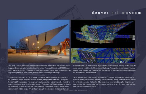
The Denver Art Museum Expansion will be a dramatic addition to the downtown Denver skyline and will<br />
help place Denver among the top <strong>art</strong> centers in the nation. The new addition will add 146,000 square<br />
feet of new exhibit space to the <strong>museum</strong>. The new wing’s design is created out of a titanium skin cladding<br />
and sculptural form, which naturally meshes with the surrounding civic buildings.<br />
d e n v e r a r t m u s e u m<br />
to create templates for the hundreds of physical models and thousands of drawings created during the<br />
design process. In addition, the 3D models and “fly-throughs” engage the <strong>museum</strong> curators in special<br />
qualities of the galleries. The models became the nucleus of communication and quickly changed how<br />
the team interacted and collaborated.<br />
The building’s rigorous geometry and sculptural form and the need to coordinate and communicate Two-dimensional construction drawings, produced from 3D models, were generated and required for<br />
the geometry to multiple disciples quickly and accurately throughout the world were a driving force regulatory building plan review and estimating. The models flowed through the design process and into<br />
for adopting BIM technologies. The design team visualized, analyzed and communicated the building the construction process. The benefits of the virtual model were realized during the design, procure-<br />
design through physical and virtual modeling methods. Technology and 3D modeling were not the drivment, detailing, fabrication, erection, and geometric control of the project. The proejct could not have<br />
ing force behind the project’s conception and ultimate form, but rather the means to understand and<br />
document, and build the design. Through the process, BIM models became invaluable as the means<br />
been constructed without these tools.<br />
© M. A. <strong>Mortenson</strong> Company, 2005. All rights reserved.
The 3D models from the design and construction teams had<br />
to work for all disciplines. The design team shared all of<br />
its 3D computer generated models. This information along<br />
with contract documents became the basis for subcontractor<br />
p<strong>art</strong>icipation in the virtual world. A file naming and layer<br />
naming nomenclature system was implemented to assure no<br />
confusion while working in the virtual environment. All prime<br />
subcontractors (Structure, Mechanical, Electrical, Plumbing,<br />
and Fire Protection) produced 3D shop drawing models. Their<br />
st<strong>art</strong>ing point was the contract documents and the initial “Master<br />
Model” (3D models).<br />
The contractor acted as the model manager linking the design<br />
models to the manufacturing (shop drawing) models used to<br />
build the project. Through this collaborative process, many<br />
different BIM software products were used to create system<br />
specific models and collaborate through a project website.<br />
All major shop drawings were submitted in 3D form. The BIM<br />
models became the catalyst for collaboration. The project<br />
team found that the models led to a new level of problem solving<br />
and a higher level of communication. The st<strong>art</strong>ing point of<br />
each discussion was not debate and definition of the problem,<br />
the model eliminated the “what is the problem” debate, but<br />
was focused on solutions.<br />
© M. A. <strong>Mortenson</strong> Company, 2005. All rights reserved.<br />
. . . p r o j e c t o u t l i n e<br />
The dynamic use of virtual solutions in the design and construction<br />
process has proven to be transformational for the<br />
project team. We have learned through the process that, if<br />
every team member is more informed and more informative effective<br />
progress is inevitable. The following process changes<br />
will illustrate the effective implementation of BIM during the<br />
design and construction process:<br />
• structural steel<br />
• concrete<br />
• mechanical/electrical/plumbing<br />
• benefits
structural steel process<br />
•<br />
•<br />
•<br />
•<br />
•<br />
•<br />
•<br />
•<br />
3D model developed by design team and used for<br />
structural analysis and geometry coordination.<br />
Wireframe model transferred to construction team<br />
Connection design performed via a collaborative<br />
team made up of local structural engineer, remote<br />
steel detailer, and local construction team made<br />
up of CM/GC, fabricator, and steel erector. BIM<br />
models were developed in Tekla Structures.<br />
Connections developed in 3D based on shop<br />
standards, erection requirements, and SAP2000<br />
analytical models built by the steel erector.<br />
3D models were exported to neutral formats for<br />
the design team review. 3D models accelerated<br />
shop drawing review.<br />
BIM models used to fabricate the structure.<br />
Complete Structural models shared with entire<br />
project team for follow-on coordination process.<br />
Field layout/survey utilized model based x,y,z coordinate<br />
points downloaded from the BIM model.<br />
steel wire frame connection model<br />
© M. A. <strong>Mortenson</strong> Company, 2005. All rights reserved.<br />
p r o c e s s c h a n g e . . .<br />
Total Station Based Survey/Control<br />
layout survey via model data<br />
superstructure - looking west
concrete process<br />
The CM|GC generated BIM models<br />
of the concrete structure for<br />
quantification, formwork design,<br />
shop drawings, and coordination.<br />
Models were submitted<br />
as 3D shop drawings to the<br />
design team. Steel/Pilaster<br />
virtual coordination resolved<br />
extensive conflicts that would<br />
have been costly jobsite conditions.<br />
Concrete model was then<br />
coordinated with the MEP and<br />
enclosure systems. Model was<br />
used for field layout and control<br />
to improve site productivity and<br />
QA/QC.<br />
steel|foundation coordination and layout<br />
© M. A. <strong>Mortenson</strong> Company, 2005. All rights reserved.<br />
. . . p r o c e s s c h a n g e<br />
concrete foundation model<br />
structure|mep coordination<br />
concrete placement
design model<br />
ceiling coordination model<br />
. . . p r o c e s s c h a n g e<br />
mep coordination model<br />
3D model overlayed with actual<br />
© M. A. <strong>Mortenson</strong> Company, 2005. All rights reserved.<br />
mep process<br />
•<br />
•<br />
•<br />
•<br />
•<br />
•<br />
•<br />
The design team developed detailed 3D models to<br />
rationalize the gallery spaces, structure, enclosure,<br />
and MEP systems.<br />
Facilitated by the model, multiple structural and<br />
mechanical systems were analyzed as p<strong>art</strong> of the<br />
design process.<br />
The design model was shared with the construction<br />
team.<br />
The CM|GC integrated the design model with the<br />
steel manufacturing model and provided it to the<br />
subcontractors as the basis for design.<br />
Pre-qualified subcontractors build system specific<br />
BIM models of each system.<br />
A 3D coordination process was used to coordinate<br />
the entire building based on all of the shared BIM<br />
models.<br />
MEP work was placed in the field based on laser<br />
survey equipment (total station) with coordinates<br />
from the models.
process benefits<br />
•<br />
•<br />
•<br />
•<br />
4D models used to simulate and visualize the project schedule – 90 day look<br />
ahead scheduled are emailed to project stakeholders via a movie file. Team members<br />
can understand thousands of schedule activities in minutes.<br />
3D coordination and collaboration allows the building to be constructed virtually<br />
prior to work in the field. Maximized ceiling heights for gallery spaces, Equipment<br />
access is modeled and reviewed with operators for serviceability, and overall<br />
design is “spell checked” prior to work on site.<br />
3D model-based layout and survey systems are used for placement and tolerance<br />
control. Model based layout avoids tolerance “stacking” as each member is<br />
placed in accordance with x, y, z coordinates. Fit-up problems were reduced and<br />
project safety increased as connection time was shortened.<br />
Model was used by construction teams to plan and build non-permanent structures.<br />
Scaffold systems, access equipment, and hoisting equipment were all<br />
added to the model to plan, communication and construct the building. The model<br />
became central to the construction process such that the means and methods of<br />
construction were added.<br />
. . . p r o c e s s c h a n g e<br />
the use of bim st<strong>art</strong>ed out as a new approach to design and project planning but led to new ways to innovate and collaborate.<br />
the model bridges the gap between the design and construction process.<br />
© M. A. <strong>Mortenson</strong> Company, 2005. All rights reserved.<br />
M O D E L B A S E D A P P R O A C H - B I M I S T H E B R I D G E<br />
bim model was the bridge to collaboration for all project stakeholders
Mechanical<br />
Design<br />
Other<br />
Consultants<br />
Structural<br />
Design<br />
t e a m c o l l a b o r a t i o n . . .<br />
Mechanical<br />
Subcontractor<br />
Concrete<br />
by<br />
CM|GC<br />
DESIGN TEAM CM|GC<br />
model flow<br />
Communication by the project team was 3D model based. The project web site became the central<br />
communication conduit as shop drawing, design communication, and RFI’s were shared via BIM models.<br />
This accelerated understanding and resultant review cycles.<br />
Collaboration of all the project stake holders through the use of 3D models. The resultant project<br />
collaboration was transformational. All of the major project stakeholders have used the experience<br />
on the project to further BIM and collaboration on subsequent projects. There is a wave of BIM utilization<br />
in the Denver market as a result intense adoption of BIM on the DAM project. The positive<br />
results were experienced by all.<br />
© M. A. <strong>Mortenson</strong> Company, 2005. All rights reserved.<br />
Electrical<br />
Subcontractor<br />
Connection<br />
Design<br />
Interiors<br />
Steel<br />
Erection<br />
Steel<br />
Fabricator
The design team first thought of sharing the 3D model similarly to sharing 2D CADD<br />
data. The team originally viewed the models as an adjunct to the 2D process. What<br />
was discovered is that the models open the door to innovation and communication<br />
at a higher level. As the project evolved, the models became central in much of the<br />
project dialog while the 2D documents became the accessory.<br />
a c u l t u r a l c h a n g e . . .<br />
faced with the challenge of this buildings’ complex geometry, we clearly had no choice but to exploit the computer’s<br />
ability to calculate, graphically portray, and communicate the critical geometries of this building. what we did not<br />
realize, however, was how valuable the three-dimensional model would become as a tool for effective multi-disciplinary<br />
collaboration, not only among the design team, but ultimately also with the constructors.<br />
project facts<br />
• Building gross s.f.: 146,000<br />
• Roof s.f. 178,000<br />
• Panels of Titanium: 9,000<br />
• Concrete: 14,500 cubic yards<br />
• Number of pieces of primary steel: 3,100<br />
• Total number of steel pieces: 16,500<br />
• Weight of steel : 2,750 tons or 5,500,000 lbs<br />
• Number of bolts is steel frame: 50,000<br />
• Field & Shop Welds: 28,000 lbs<br />
© M. A. <strong>Mortenson</strong> Company, 2005. All rights reserved.<br />
working session<br />
4D model<br />
slab-on-metal-deck placement plan<br />
working session
esults of bim collaboration<br />
•<br />
•<br />
•<br />
•<br />
•<br />
•<br />
•<br />
•<br />
•<br />
•<br />
•<br />
Over 1,200 collisions were discovered prior to steel arrival.<br />
Precision surveying data allowed sleeves to be fit early – field concrete core drilling and field steel sleeve installation was<br />
virtually eliminated.<br />
Issues were resolved and steel was completed three months ahead of schedule – reducing <strong>Construction</strong> Administration<br />
costs and subcontractor general conditions.<br />
Steel structure consisting of angular shards of titanium was created, modeled, and detailed in 3-dimensional software<br />
before the groundbreaking took place.<br />
Mechanical, electrical, and fire protection systems were modeled and coordinated in 3D software to avoid any potential<br />
for collisions and to ensure future access to equipment and systems.<br />
The MEP and finish trades used total station x,y,z coordinates to perform layout and automate field placement.<br />
Productivity was increased.<br />
Project schedule was maintained by using the model to ensure coordinate points and avoid the cycle of waiting for “field<br />
verified” dimensions. Model based layout was a new tool to ensure tolerance management.<br />
Conflict Resolutions were based on the best “global” solution for the project.<br />
Sharing of 3-D Models – all follow-on work was based on the manufacturing model to ensure accuracy and coordination.<br />
The complex, world-class project will be delivered on-time!<br />
. . . i t w o r k s !<br />
solid model used to define scaffold|access during construction<br />
4D animation - click on image to play<br />
r e s u l t s o f b i m i m p l e m e n t a t i o n a n d e f f e c t i v e team collobration<br />
Steel erection was completed three months early. This allowed the contractor to return nearly $400,000 to the City and County of Denver.<br />
© M. A. <strong>Mortenson</strong> Company, 2005. All rights reserved.