Aaton 35 - Panavision
Aaton 35 - Panavision
Aaton 35 - Panavision

You also want an ePaper? Increase the reach of your titles
YUMPU automatically turns print PDFs into web optimized ePapers that Google loves.
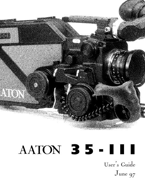
<strong>35</strong>-III<br />
User’s Guide<br />
June 97
INTRODUCTION<br />
3
The AATON <strong>35</strong>-III User Guide<br />
AATON<br />
2 rue de la Paix<br />
BP3002<br />
38000 Grenoble<br />
FRANCE<br />
+33 4 7642 9550<br />
+33 4 7651 3491 fax<br />
E-mail: support@aaton.com<br />
Web: http://www.aaton.com<br />
(c) June 1997 <strong>Aaton</strong> / Grenoble , France.<br />
Limitation of Liability<br />
The information contained in this manual is distributed without warranty of any kind, express or implied. To the maximum<br />
extent permitted by law, <strong>Aaton</strong> and its licensors disclaim any and all warranties, express or implied, by statute or<br />
otherwise, regarding this manual, including the fitness for a particular purpose, quality, or merchantability. Under no circumstances<br />
shall <strong>Aaton</strong> or its licensors be liable to the user of this manual or any other person for any incidental, special,<br />
or consequential damages resulting from the use of this manual or the operation of the equipment described therein,<br />
whether arising out of breach of warranty, breach of contract, or otherwise. Under no circumstances shall <strong>Aaton</strong> or its<br />
licensors be liable for any damages arising out of the operation of the equipment described in this manual, whether operated<br />
in a manner which is consistent with or contrary to the instructions contained therein, for physical abuse or misuse<br />
of the equipment. No oral or written information or advice given by <strong>Aaton</strong> or its licensors, their respective employees,<br />
distributors, dealers, or agents, shall create any warranty. <strong>Aaton</strong> and its licensors further disclaim any and all warranties,<br />
express or implied, by statute or otherwise, regarding this manual, including the fitness for a particular purpose, quality,<br />
or merchantability, regarding the equipment described in this manual, and in no event shall <strong>Aaton</strong> or its licensors be<br />
liable for any damages, including but not limited to incidental, special, or consequential damages, arising out of the use<br />
of the equipment, or any exposure of motion picture film used in the equipment.<br />
4
1 GENERAL OVERVIEW<br />
Front View 12<br />
Rear View 13<br />
Battery Side 14<br />
Motor Side 15<br />
LCD Control Panel - Quick Reference 16<br />
2 THE CAMERA BODY<br />
TABLE OF CONTENT<br />
2.1 Lenses 20<br />
Arri PL Lens Port 20<br />
Installing the Lens 20<br />
2.2 Viewing System 20<br />
Viewfinder Options 20<br />
Installing the Extension Finder 21<br />
Viewfinder Tension Adjustments 22<br />
Adjusting the Diopter 22<br />
The Eyepiece Shutter 23<br />
Adjusting the Viewing Horizon 23<br />
Viewing Screen 23<br />
Changing the Viewing Screen 24<br />
Adjusting the Viewing Screen 25<br />
2.3 Mirror Shutter 25<br />
Concept 25<br />
Adjusting the Shutter 26<br />
2.4 Film Gate and Pulldown Claw 27<br />
Adjusting the Pitch 27<br />
The Side Pressure Bar 28<br />
2.5 Flange Focal Distance Adjustment 28<br />
Concept 28<br />
Polishing a Spacer 28<br />
Changing a Spacer 29<br />
Adjusting the Viewing Screen 29<br />
Flange Focal Distances 29<br />
5
6<br />
2.6 Magazine 30<br />
Installing the Magazine 30<br />
Removing the Magazine 31<br />
2.7 Power 31<br />
Installing the Battery on the Camera 31<br />
Battery Charging 32<br />
Other Power Options 32<br />
2.8 Motor 33<br />
Camera Speeds 33<br />
Using External Speed Devices 34<br />
Electronic Inching 34<br />
Single Frame Operation <strong>35</strong><br />
2.9 LCD Control Panel and Jog 34<br />
The <strong>Aaton</strong> Jog <strong>35</strong><br />
Understanding the Control Panel <strong>35</strong><br />
<strong>Aaton</strong>Code 36<br />
ASA Setting 36<br />
Battery Voltage 37<br />
Magazine Number 37<br />
Camera Preset Speed 37<br />
Camera Specific Speed 37<br />
Speed Phasing 38<br />
Remaining Footage 38<br />
Elapsed Footage 38<br />
Camera Software Version Number 38<br />
Footage Total Recall 39<br />
Warning 39<br />
2.10 LED Indicators 39<br />
Position and Meaning of the Diodes 39<br />
Camera Test Indicator 39<br />
Camera Run Indicator 39<br />
Low Battery Indicator 40<br />
Low Speed Indicator 40<br />
2.11 Video Assist 40<br />
The CD56 Color CCD Assist 41<br />
Installing the Control Unit 41
Menu Operations 42<br />
3 THE MAGAZINE<br />
Concept 48<br />
Pressure Plate System 48<br />
The Gate Plate 48<br />
The Picture Plate 48<br />
Loading 49<br />
First Step, in Daylight 49<br />
Loading, in the Dark 50<br />
Adjusting the Loop 51<br />
4 THE AATON SYSTEM<br />
TABLE OF CONTENT<br />
Camera Configurations 56<br />
15mm Front Rods 56<br />
Sliding Bridgeplate 56<br />
Handgrip 57<br />
Mounting the Handgrip 57<br />
Handgrip On/Off Functions 57<br />
Handgrip Adjustment 58<br />
Tripod Use 58<br />
Shoulder Operation 58<br />
Carrying Handle 59<br />
3/8 Accessory Screw 59<br />
Mounting from the Carrying Handle 59<br />
Tape Measure Hook 59<br />
Transport 60<br />
Extreme Conditions 60<br />
Cold Weather 61<br />
Warm Weather 61<br />
7
8<br />
5 CLEANING<br />
5.1 Lens 64<br />
Lens Elements 64<br />
Lens Exterior 64<br />
Mounting Surface 64<br />
5.2 Body 64<br />
Exterior 64<br />
Mounting Surfaces 65<br />
Camera Gate 65<br />
5.3 Viewing System 65<br />
Viewing Screen 66<br />
Eyepiece 66<br />
Viewfinder 66<br />
5.4 Magazine 66<br />
Exterior 66<br />
Pressure Plates 66<br />
Interior / Film Path 67<br />
6 SUPER<strong>35</strong><br />
6.1 Super<strong>35</strong> 70<br />
The Format 70<br />
When to Shoot Super<strong>35</strong> 70<br />
6.2 Super<strong>35</strong> Field Conversions 71<br />
Changing the Viewing Screen 71<br />
Shifting the Viewfinder 71<br />
Shifting the PL Lens Port 71<br />
Shifting the Video Assist 72<br />
7 3-PERF FORMAT<br />
7.1 Concept 76<br />
7.2 The AATON <strong>35</strong>-III 3-Perf Camera Body 76
8 AATONCODE<br />
8.1 Concept 80<br />
8.2 The Internal Clock 80<br />
8.3 OriginC plus MasterClock 81<br />
8.4 Initializing <strong>Aaton</strong>Code in the Camera 81<br />
Using the OriginC plus - Recommended Method 82<br />
Using an External SMPTE Device 82<br />
8.5 Monitoring and Maintaining <strong>Aaton</strong>Code 83<br />
Monitoring <strong>Aaton</strong>Code with OriginC plus 83<br />
Maintaining <strong>Aaton</strong>Code without OriginC plus 83<br />
8.6 GMT1 Smpte Generator 84<br />
8.7 The Camera’s Assistant Duties 84<br />
Checking the Diodes 84<br />
Setting the ASA 85<br />
9 TECHNICAL SPECIFICATIONS<br />
TABLE OF CONTENT<br />
List of Specifications 88<br />
Connector - Pin Attributions 89<br />
Viewing Screens 90<br />
9
1<br />
GENERAL OVERVIEW<br />
11
1<br />
2<br />
3<br />
4<br />
5<br />
6<br />
7<br />
8<br />
9<br />
10<br />
1.1 FRONT<br />
1 Eyepiece<br />
2 Friction Adjusting Ring adjusts the tension of the eyepiece swivel<br />
3 Diopter Set Ring adjusts the diopter setting of the viewfinder to the operator’s eye<br />
4 Lateral Lock Knob locks the lateral position of the viewfinder<br />
5 PL Lens Port<br />
6 CCD Control Unit<br />
7 CCD Friction Ring<br />
8 Lens Locking Ring<br />
9 Wooden Handgrip<br />
10 15mm Front Rods<br />
12
11<br />
12<br />
13<br />
14<br />
15<br />
16<br />
17<br />
18<br />
19<br />
20<br />
1.2 REAR<br />
GENERAL OVERVIEW<br />
11 Pitch and Mirror Shutter Adjusting Tools<br />
12 CCD Led - On/Off indicator<br />
13 Magnetic wheel for the magazine’s sprockets<br />
14 XLR4 Connector allows for the battery connection<br />
15 Aperture Opening<br />
16 Battery Locking Screw<br />
17 Magnetic Wheel for the magazine’s take-up core<br />
18 LCD Control Panel displays <strong>Aaton</strong>Code, ASA, speed, voltage, or remaining footage<br />
19 Jog Wheel provides quick adjustment of ASA, speed, and phasing<br />
20 Lemo5 Connector for <strong>Aaton</strong>Code and SMPTE communication<br />
13
21<br />
22<br />
23<br />
24<br />
25<br />
26<br />
27<br />
28<br />
29<br />
30<br />
1.3 BATTERY SIDE<br />
21 Carrying Handle<br />
22 Base of the carrying handle and viewing system block<br />
23 Guiding Pin for the magazine<br />
24 Amph9 Connector connects the CCD unit to the camera body<br />
25 Cap covering the viewing screen holder<br />
26 Magazine Connector<br />
27 Coupler allows for the handgrip attachment<br />
28 Guiding Grooves for the Magazine<br />
29 LED Indicators<br />
30 Run/Test Switch provides camera Run and half frame inching<br />
14
31<br />
32<br />
33<br />
<strong>35</strong><br />
36<br />
37<br />
38<br />
39<br />
40<br />
1.4 MOTORS SIDE<br />
31 Eyepiece Shutter blocks light when operator’s eye is away from the viewfinder<br />
32 Lemo6 Connector<br />
33 Lemo8 Connector<br />
34 Led Indicators<br />
<strong>35</strong> Handgrip Run/Test Switch provides camera run and full frame inching<br />
36 Lemo2 Connector<br />
37 Magazine’s Take-up Core Motor<br />
38 Handgrip T-Screw<br />
39 Mag Release Lever<br />
40 Magazine’s Sprockets and Camera Pulldown Claw Motor<br />
GENERAL OVERVIEW<br />
34<br />
15
1.5 LCD CONTROL PANEL - QUICK REFERENCE<br />
IN SHOW MODE<br />
24’ - 080 Camera speed and Remaining footage (default mode)<br />
ISO = 100 Film ASA (1 x Batt/Iso)<br />
Batt = 10’4 Battery voltage (2 x Batt/Iso)<br />
MAG =0071 Magazine number (3 x Batt/Iso)<br />
Sp = 27’454 Camera Speed (1 x Speed)<br />
Ela = 042 Elapsed footage during last take (2 x Speed)<br />
22=32=54 Hours=minutes=seconds in <strong>Aaton</strong>Code (1 x Time)<br />
95-03-25 Year-Month-Day in <strong>Aaton</strong>Code (2 x Time)<br />
123456 Production ID in <strong>Aaton</strong>Code (3 x Time)<br />
2321 Equipment number in <strong>Aaton</strong>Code (4 x Time)<br />
IN SET MODE<br />
Sp =2 4’ Adjusting a preset speed (SET, 1 x SYNC, toggle SYNC or use Jog)<br />
Sp = 27’454 Adjusting a specific speed (SET, 1 x VAR, use Jog)<br />
Et Speed controled by external speed device (SET, 2 x VAR)<br />
Phase Phase Adjusting (Camera running,SET, 2 x VAR, use Jog)<br />
ISO = 100 ASA Setting (SET, 1 x ISO, toggle ISO or use Jog)<br />
WARNINGS<br />
Lo Spd Camera has not yet reached the selected speed<br />
Lo Batt Battery is too low (below 10V)<br />
Loop Film loop is too small<br />
Scratch Something is wrong in the magazine<br />
Empty No more film in the magazine<br />
Unadjust Please check page 39<br />
16<br />
Test<br />
Run<br />
Time speed<br />
VAR<br />
ISO / Batt<br />
SET<br />
SYNC<br />
ISO
GENERAL OVERVIEW<br />
17
2<br />
THE CAMERA BODY<br />
19
Flange focal distance.<br />
Refers to the critical distance<br />
from the lens seat to the film<br />
plane. With the PL port, the<br />
precise FFD of the AATON<br />
<strong>35</strong>-III is 52mm -40 to -50<br />
microns as measured with a<br />
depth gauge in the lens port.<br />
With the PV port, the FFD is<br />
57.15mm -60 to -70 microns<br />
It is recommended that these<br />
tolerances be checked and<br />
maintained by a qualified technician.<br />
The combination of<br />
FFD and back focus distance<br />
of a lens directly affects precise<br />
focus and overall image sharpness.<br />
Make sure these critical<br />
measurements are strictly<br />
upheld. When using an unfamiliar<br />
lens for the first time,<br />
check that the eye focus<br />
matches the tape-measured<br />
focus marks on the lens, and/or<br />
shoot a focus test.<br />
20<br />
2.1 LENSES<br />
The AATON <strong>35</strong>-III’s flexible lens mounting system allows for the use of<br />
a wide variety of <strong>35</strong>mm lenses.<br />
2.1.1 ArriPL Lens Port<br />
The ArriPL lens port is the standard mounting system delivered<br />
with the AATON <strong>35</strong>-III and allows the use of all <strong>35</strong>mm ArriPL<br />
mounted motion picture lenses. PL lenses adaptors are available for<br />
Arri standard and Arri bayonet mounted lenses. This lens port is<br />
ideal for rental facilities, where a mounting system compatible with<br />
other manufacturer’s <strong>35</strong>mm cameras is often desired.<br />
If you need to get a <strong>Panavision</strong> or Nikon mount, please contact a<br />
certified <strong>Aaton</strong> technician.<br />
2.1.2 Installing the Lens<br />
To install the lens on the camera body, turn the outer locking ring<br />
counter-clockwise. If the port cap is on, remove it. Align the four<br />
protruding flanges on the lens with the four corresponding cutaways<br />
in the locking ring and insert the lens into the camera port so that<br />
its flanges rest evenly against the lens seat. Tighten the locking ring<br />
by turning clockwise until the lens is secured in place and the locking<br />
ring is firmly set. Make sure the locking ring is tight enough so<br />
that it cannot be inadvertantly unlocked.<br />
VIEWING SYSTEM<br />
2.2.1 Viewfinder Options<br />
The viewfinder is designed to be fully orientable, providing left or<br />
right side viewing and upright image in any position. The viewfinder<br />
comes equipped with a standard short eyepiece that can be used<br />
for handheld and tripod-mounted operation. For more comfortable<br />
tripod and studio applications, the standard extension finder(200<br />
mm) can be fitted in place of the short eyepiece. With an Elemak or
Mitchell type dolly, or in situations requiring additional reach, the<br />
hyperlong (400 mm) finder, which is twice as long as the standard<br />
extension finder, can be used.<br />
The <strong>Aaton</strong> hyperlong finder integrates as a standard feature a heating<br />
system designed to fight mist. A heating system kit is also available<br />
for the standard eyepiece.<br />
2.2.2 Attaching the Extension Finder<br />
In order to use an extension finder on the AATON <strong>35</strong>-III, the standard<br />
eyepiece must first be removed To remove the eyepiece, locate<br />
the eyepiece lock ring, marked a in the image below. Rotate counterclockwise<br />
until the ring reaches its stop and gently pull off the eyepiece.<br />
To install the extension finder, locate the protruding guide<br />
b<br />
d<br />
c<br />
a<br />
THE CAMERA BODY<br />
The Pechan Prism<br />
In order to provide a fully<br />
orientable upright image, the<br />
<strong>Aaton</strong> viewfinder incorporates<br />
a Pechan prism assembly, which<br />
is actually comprised of two<br />
triangular prisms sandwiched<br />
together. On some viewfinders,<br />
depending of the construction<br />
of this prism, rotation of the<br />
eyepiece a full 360°will cause<br />
the image in the finder to shift<br />
slightly left or right.<br />
After attaching an extension<br />
finder, if the image in the finder<br />
appears to have shifted<br />
slightly, rotate the finder 360°<br />
and choose the preferred centered<br />
image.<br />
21
22<br />
pin on the seat of the viewfinder and align the pin with the hole in<br />
the flange of the finder. Make the flange to the seat of the viewfinder<br />
and tighten the lock ring until it is set firmly in place. During<br />
this procedure, you will notice that the extension finder needs to<br />
face 180° away from the operator’s eye to be installed on the viewfinder.<br />
Because of its optical construction, this is completely normal.<br />
After installation, rotate the finder 180° to regular viewing position.<br />
2.2.3 Viewfinder Tension Adjustments<br />
The large knurled knob at the base of the left/right lateral movement<br />
point (B) locks the lateral positioning.<br />
The friction adjusting ring, located behind the eyepiece lock ring,<br />
can be used to adjust the tension of the eyepiece swivel, depending<br />
on the operator’s preference and the viewfinder being used.<br />
When using the standard eyepiece, tension should be relatively light<br />
to allow for movement with a moderate amount of pressure.<br />
When using a standard extension finder, tension should be increased<br />
to hold the additional weight of this finder in place.<br />
To adjust the tension of the swivel, loosen the steel knurled screw<br />
(C) located on the friction adjusting ring. Hold the eyepiece in place,<br />
rotate the adjusting ring slightly and retighten the screw; 1/8 of a<br />
turn, at first, will have an effect. To increase the tension of the eyepiece<br />
swivel, rotate the adjusting ring clockwise; to decrease the tension,<br />
rotate the adjusting ring counter-clockwise.<br />
2.2.4 Adjusting the Diopter<br />
Before shooting, the diopter setting of the viewfinder should be<br />
adjusted to the operator’s eye. To set the diopter, locate the diopter<br />
set ring (D) in front of the carrying handle at the top of the viewfinder,<br />
and loosen the small knurled knob. Look through the viewfinder,<br />
rotate the diopter set ring until the edge of the cross-hair is at<br />
its sharpest point and retighten the knob. It is recommended that,<br />
for easiest setting, this adjustment be performed with the port cover<br />
off and no lens on the camera.<br />
Notice that the diopter set ring is engraved with numbers and dots
-use this reference to quickly recall your particular setting when<br />
more than one person will be looking through the viewfinder.<br />
If a corrective lens is required, one can be fitted in the recessed area<br />
of the eyecup ring of both the standard eyepiece and the extension<br />
finder.<br />
2.2.5 The Eyepiece Shutter<br />
In order to avoid light seepage through the viewfinder, the eyepiece<br />
shutter must be closed any time the camera is running film and the<br />
operator’s eye is away from the viewfinder.<br />
Locate the black wheel under the base of the carrying handle. To<br />
close the eyepiece shutter, turn this wheel counter-clockwise. To<br />
open it, turn the wheel clockwise.<br />
2.2.6 Adjusting the Viewing Horizon<br />
If the rotation of the image seen through the camera’s viewfinder<br />
does not exactly match what is seen through the naked eye, there is<br />
a fine adjustment that can be made to the image’s relative horizon.<br />
Locate the small slotted screw located on the underside of the viewfinder<br />
inside the eyepiece lock ring. Notice that the screw travels in<br />
an elongated cutout. Loosen the screw one turn and, while looking<br />
through the viewfinder, move the screw within its cutout in order to<br />
adjust the horizontal rotation. When the images seen through your<br />
left and right eyes coincide, lock the screw.<br />
2.2.7 Viewing Screen<br />
The AATON <strong>35</strong>-III utilizes an interchangeable viewing screen (or<br />
“ground-glass”) system which allows the cinematographer to install<br />
the screen which best suits his particular application. <strong>Aaton</strong> offers<br />
12 viewing screens as standard (see section Viewing Screens in the<br />
Technical Specifications chapter).<br />
Custom screens can also be manufactured upon request. Contact<br />
your local <strong>Aaton</strong> representative for details.<br />
2.2.8 Changing the Viewing Screen<br />
THE CAMERA BODY<br />
Checking your viewing<br />
horizon<br />
there is a simple means of<br />
determining whether adjustment<br />
of the horizon needs to<br />
be made. Mount a zoom lens<br />
onto the camera and rest the<br />
camera on your shoulder in a<br />
standard handheld position.<br />
Look through the viewfinder<br />
with your right eye while also<br />
keeping your left eye open.<br />
Compose a frame that includes<br />
vertical or horizontal<br />
lines (a window frame for<br />
example) and adjust the zoom<br />
on the lens so that the focal<br />
length of the lens generally<br />
matches what you see with<br />
your left eye.<br />
Ignore the viewing screen markings<br />
for the time being and<br />
determine whether the rotation<br />
of the image you see through<br />
the viewfinder matches what<br />
you see with your left eye. If it<br />
does not, then a find adjustment<br />
may be necessary.<br />
23
24<br />
post-it<br />
screen<br />
The viewing screen is designed to be easily removed by the user for<br />
the purpose of interchanging or for cleaning. To remove the screen,<br />
first remove the port cap. Remove the battery and clear the mirror<br />
shutter so that it is positioned safely inside the body by rotating at<br />
the base of the shutter with your finger. Look into the port and<br />
locate the screen directly above the aperture opening. To operate,<br />
use a piece of Post-it, that will take the viewing screen without dirtying<br />
it. Put the Post-it on your forefinger, the sticking part of it<br />
facing up. Smoothly put your finger on the viewing screen, and<br />
remove it.<br />
To reinstall the screen, look into the port and locate the right and<br />
left lip of the viewing screen holder. The grounded side of the viewing<br />
screen should face down. Proceed as before, with a piece of<br />
Post-it on your finger.<br />
2.2.9. Adjusting the viewing screen :<br />
The image focus on the viewing screen (or “ground-glass”) should<br />
match the lens barrel focus mark and the focus on the film. Before<br />
adjusting the viewing screen, be certain that the flange focal distance
of the camera is set according to the manufacturer specifications. 52<br />
mm ,57.15 mm and that the lens used is correctly adjusted ; this<br />
can be determined by the use of a collimator. It is preferable to use a<br />
“wide angle lens” i.e. : less than 25 mm. To proceed, you must first<br />
unscrew and remove the circular Cap located on the upper side of<br />
the rectangle plate, above the battery locking screw. Inside the access<br />
hole, locate the screen holder that you can unlock by turning its<br />
Allen screw counterclockwise. Set your focusing chart at a measured<br />
distance. Set the focus mark of the lens at the exact same distance (<br />
Adjust the diopter ! ) you can, now, focus the<br />
ground-glass, moving the holder up or down by turning the <strong>Aaton</strong><br />
two pins tool. Lock the Allen screw. Double check the focus of the<br />
viewing screen using the focus ring of the lens. If the image is still<br />
not sharp, proceed again.<br />
2.3 MIRROR SHUTTER<br />
2.3.1 Concept<br />
The reflex mirror shutter is designed to provide an optical path to<br />
the viewfinder while the claw movement advances the film to the<br />
next frame.<br />
The shutter features a four-position user-adjustable opening.<br />
• Standard180° for filming<br />
under standard 60 Hz HMI lighting at 24 fps<br />
or under standard 50 Hz HMI lighting at 25 fps<br />
without flicker.<br />
• 172.8° for filming<br />
under 50 Hz HMI lighting at 24 fps<br />
without flicker.<br />
• 150° for filming<br />
under 60 Hz HMI lighting at 25 fps<br />
THE CAMERA BODY<br />
Always Remove the<br />
Battery<br />
Each time you need to go inside<br />
the camera body, you must<br />
first remove the battery. If, by<br />
mistake, the camera starts running<br />
while you finger is rotating<br />
the mirror shutter, the<br />
mechanism of the camera body<br />
could be seriously damaged.<br />
25
26<br />
without flicker.<br />
• 144°<br />
to minimize the roll bar while filming<br />
NTSC broadcast monitor at 24 fps.<br />
2.3.2 Adjusting the shutter<br />
To adjust the shutter opening, unscrew the shutter tool marked<br />
“Sh” located in the hollow at the rear of the camera’s carrying handle.<br />
Make sure that the battery is off the camera and remove the port<br />
cap. Locate the tool guiding hole to the lower right of the inside lens<br />
holder. Gently rotate the shutter at its base with your finger until<br />
the brass driving gear is centered underneath the tool guiding hole.<br />
Insert the shutter tool through the guiding hole and into the brass<br />
gear. Rotate the tool until the appropriate notched shutter setting is<br />
reached ; turning counter-clockwise will reduce the shutter opening,<br />
turning clockwise will increase the opening.<br />
When setting the opening to 172.8°, 150° or 144°, a shutter blade<br />
indicating these settings will be visible from behind the left edge of<br />
the mirror. Make sure the white line to the immediate right of the<br />
172.8°, 150° and 144° markings meet the left edge of the mirror.<br />
tool guiding hole
When the adjustment is complete, remove the tool and store back in<br />
the hollow of the carrying handle.<br />
2.4 FILM GATE AND PULLDOWN CLAW<br />
2.4.1 Adjusting the Pitch<br />
To adjust the pitch, use the tool (Ref 09.203.65) located at the rear<br />
of the camera carrying handle.<br />
Looking at the camera with the lens port facing you, locate the<br />
small opening situated between the two camera front rods, closer to<br />
the left rod. Using the tool, you can undo the Allen screw retaining<br />
the opening cover. Insert the tool inside the opening. You will "feel"<br />
a screw that you will turn counter-clockwise until it stops. The length<br />
of the pulldown is now at its maximum.<br />
Put the loaded magazine on the camera, and keeping the tool in<br />
position, inch and run the camera. The camera will run with a "clicking<br />
noise", due to the perf being hit by the claw. Turn the tool<br />
clockwise until you reach a more pleasant noise, like a loud "purring".<br />
If you go too far, you will hear one "clack" noise indicating<br />
that the claw lost a perforation. If more than one "clack" is heard,<br />
the camera display will show "LOOP".<br />
Once you reach the proper setting, it is recommended to turn the<br />
tool counterclockwise, approximately 20º, to accomodate any variation<br />
of the film pitch that occures between different film stocks or<br />
under humid or hotweather conditions. To do this adjustment, use<br />
the film stock you are most likely to use.<br />
2.4.2 The Side Pressure Bar<br />
The film gate also features a side pressure bar which is recessed into<br />
the claw-side rail at the point of image exposure to insure maximum<br />
lateral stability.<br />
2.5 FLANGE FOCAL DISTANCE<br />
ADJUSTMENT<br />
THE CAMERA BODY<br />
27
28<br />
2.5.1 Concept<br />
For a few years now, <strong>Aaton</strong> has inserted a spacer between the lens<br />
port and the camera body. This thin (0.3mm) metallic ring is responsible<br />
for the precise distance between the lens port seat and the<br />
film plane called the flange focal distance (FFD), and therefore it is<br />
also mainly responsible for the sharpness of the images.<br />
In order to change the FFD of the AATON <strong>35</strong>-III, simply change<br />
the spacer, and only the spacer. Do not polish any other surface, or<br />
insert anything else between the lens port and the film plane. For<br />
fine adjustment of the FFD, order some aluminium spacers<br />
(0.<strong>35</strong>mm) from your <strong>Aaton</strong> agent, and then safely change the FFD<br />
of your camera.<br />
2.5.2 Polishing a Spacer<br />
In order to fine-adjust the thickness of a specific spacer, <strong>Aaton</strong> carries<br />
a specific tool (ref <strong>35</strong> 310 32) designed to hold the spacer firmly<br />
and evenly against polishing paper. When polishing a spacer, always<br />
work on a perfectly flat worktable or stone, and be sure to firmly<br />
hold the tool.<br />
2.5.3 Changing the Spacer<br />
The spacer is placed between the PL lens port and the camera body’s<br />
titanium base. First, remove the lens locking ring: screw two or three<br />
turns its stop (placed on the bottom, inside the PL port), and turn<br />
the ring counterclockwise. Remove the PL port by unscrewing its 6<br />
screws. Then gently remove the aluminium spacer .<br />
Once you have placed a new spacer, install the PL port, then the<br />
lenses locking ring, and do not forget to unsrew two or three turns<br />
the locking ring stop.<br />
2.5.4 Adjusting the Viewing Screen<br />
Because you have changed the distance separating the base of the<br />
lens and the camera body, the image on your viewing screen might<br />
now appear to be less sharp than usual. Most likely, you may need
to readjust the precise focus of the viewing screen. Refer to the 2.9<br />
section of this chapter to proceed.<br />
2.5.5 Flange Focal Distances<br />
Here are the flange focal distances for all the lens ports available for<br />
the AATON <strong>35</strong>-III. Remember that these distances are automatically<br />
shorter by 0.3mm than the indicated ones (because of the needed<br />
spacer)<br />
2.6 MAGAZINE<br />
The <strong>Aaton</strong> magazine holds 400ft (122m) of <strong>35</strong>mm film, which represents<br />
4’28’’ shooting at 24fps in <strong>35</strong>mm 4-Perf, and 5’26’’ shooting at<br />
24fps in <strong>35</strong>mm 3-Perf.<br />
2.6.1 Installing the Magazine<br />
To install the mag, situate yourself at the rear of the camera body,<br />
battery side. Do not forget to remove the aperture plate cover.<br />
Place your left hand underneath the magazine while your right hand<br />
is firmly holding it at the midway point of its rear. Rest the nose of<br />
the magazine on the camera base, hold the camera body with your<br />
left hand while pushing the mag in the bottom dovetail and into the<br />
aperture area with your right hand. Make sure that the top of the<br />
"nose" of the mag is parallel to the camera carrying handle as you<br />
guide the mag in place. Push firmly and evenly until you feel and<br />
hear that the mag snaps against the aperture area. The mag nose<br />
should be pressed against the camera body's rubber seal. This operation<br />
should be done without having to force the mag into position.<br />
THE CAMERA BODY<br />
Mount Référence FFD Diameter Adjustment<br />
Arriflex (PL) <strong>35</strong> 340 30 52.00 mm 54.00 mm -40 / -50 microns<br />
<strong>Panavision</strong> (PV) <strong>35</strong> 330 30 57.15 mm 49.50 mm -60 / -70 microns<br />
Nikon (Ni) <strong>35</strong> 360 10 46.44 mm 43.53 mm -40 / -50 microns<br />
29
30<br />
2.6.2 Removing the Magazine<br />
To remove the magazine, situate yourself at the rear of the camera<br />
body, battery side. Place your right hand palm on the camera takeup<br />
motor and pull the mag lock lever towards the rear of the camera<br />
with your fingers.<br />
The mag will be toward the rear of the camera. The mag is now free<br />
to be pulled offthe camera, using both your hands.<br />
2.7 POWER<br />
The AATON <strong>35</strong>-III body requires only 12 volts for all aspects of operation.<br />
One standard <strong>Aaton</strong> on-board (12V, 1.8 Ah, rechargeable, nicad)<br />
will power the camera, CCD and accessories which are connected to the<br />
body’s accessory inputs (such as zoom controls, speed controls, etc.)<br />
through a standard 4 pin XLR connector. One 1.8 ah on-board battery<br />
will run 7-8 magazines on the AATON <strong>35</strong>-III, without CCD and<br />
accessories. With accessories in use, this number will decrease.<br />
2.7.1 Installing the Battery on the Camera<br />
The on-board battery fits above the LCD conrol panel. In order to<br />
install, loosen the black knurled screw approximately four or five<br />
turns. Push the battery evenly onto the XLR4 connection of the
ody. When snug, tighten the knurled screw onto the battery tab to<br />
hold it in place.<br />
When running <strong>Aaton</strong>Code, get into the practice of having a fresh<br />
battery on hand before removing the one from the camera. Even a<br />
low battery that no longer runs the body (below 10V) will have<br />
enough voltage to keep accurate time counting.<br />
Thanks to a super capacitor built into the camera base you will have<br />
a full minute to change the battery before time is lost. After replacing<br />
the battery, confirm that time is still counting by checking the<br />
control panel.<br />
2.7.2 Battery Charging<br />
The <strong>Aaton</strong> on-board can be recharged with an appropriate 12V<br />
nicad battery charger.<br />
For the best results, use a microprocessor-controlled charger or a<br />
standard trickle charger with a charging output of at least 200ma,<br />
both of which prevent of the overheating and mistreatment of your<br />
nicad cells. Always follow the specific guidelines of the charger<br />
manufacturer. You can use the <strong>Aaton</strong> Chr1, designed to charge two<br />
standard batteries in 6 hours, without any risk.<br />
Beware of older, timed chargers manufactured when 1.2 and 1.4ah<br />
THE CAMERA BODY<br />
31
Nicad Battery Tips<br />
Follow a few simple rules to<br />
insure the long life of your<br />
nicad cells:<br />
• Allow the battery to run<br />
through their normal cycle of<br />
charging and use. Avoid topping<br />
off partially full batteries.<br />
Once every few months,<br />
discharge cells to 8-10V using<br />
a standard discharger to minimize<br />
their memory.<br />
• Do not rapid-charge your<br />
cells more than necessary, as<br />
the added heat will eventually<br />
shorten their life span. Instead<br />
recharge batteries at a normal<br />
charging rate when your schedule<br />
allows.<br />
• If your batteries will not be<br />
used for long periods of time,<br />
always store them in a cool dry<br />
environment fully charged.<br />
32<br />
batteries where the norm; these chargers where most likely rated for<br />
the lower amperage batteries of that time and will consistently<br />
undercharge the higher rated nicad cells of today.<br />
2.7.3 Other Power Options<br />
Since the AATON <strong>35</strong>-III power input is a standard 4 pin XLR type,<br />
a great varitey of 12-14 volt sources can be used to power the camera.<br />
This includes AC power supplies, battery blocks, lithium cells<br />
and car batteries.<br />
Get into the habit of carrying a standard XLR4 powercable in your<br />
package in case an alternative power source is needed.<br />
Regarding AC power supplies, it is recommended that the unit you<br />
use be at least 5 A and 25 W. Before connecting any non-standard<br />
source, always make sure that the pin configuration of the unit is<br />
correct. See the Technical Specifications chapter of this manual for<br />
details for proper wiring.<br />
2.8 MOTOR<br />
The tri-phase samarium design of the AATON <strong>35</strong>-III provides low<br />
power consumption and improved stability at high speeds. The<br />
body is capable of speeds between 3 and 40 fps with a standard<br />
12V battery.<br />
2.8.1 Camera Speeds<br />
The AATON <strong>35</strong>-III provides boths preset crystal speeds (in sync<br />
mode) and specific crystal speeds (in variable mode) in .001 increments,<br />
all accessible from the LCD control panel.<br />
Available preset speeds consist of 6, 12, 18, 23.98, 24, 25, 29.97<br />
and 30. The preset speed selector (SYNC) allows for quick access to<br />
these frequently used speeds.<br />
If any other speed is desired, or if the camera speed must match the<br />
frequency of a monitor to eliminate a roll bar, the specific speed<br />
selector (VAR) should be employed. The specific speed selector
enables the body to run at any speed between 3 and 40 in .001 frame<br />
increments. A phase adjustment of the variable speed is accessible<br />
from the VAR selector and jog wheel.<br />
The camera speed can also be adjusted while the camera is running<br />
in either sync or variable mode. For more information on these<br />
speed functions, refer to section LCD Control Panel and Jog of this<br />
chapter.<br />
2.8.2 Using External Speed Devices<br />
The AATON <strong>35</strong>-III can be driven externally from devices such as<br />
film/video synchronizers, speed aperture computers and external<br />
speed controls. In these situations, the camera VAR selector must be<br />
set to Et. If such a device is connected and the selector is not set to<br />
Et, the camera will run at the speed indicated on the display.<br />
Keep in mind that, with certain manufacturer’s speed controls, it<br />
may be possible to run the camera at speeds higher than the 40 fps<br />
factory limitation. Overcranking in such a way, however, will increase<br />
mechanism wear, increase noise and compromise image registration.<br />
<strong>Aaton</strong> urges to avoid such usage at all cost and will not be responsible<br />
for the resulting damage that will occur. This top speed cap<br />
of 40 fps has been designated by <strong>Aaton</strong> because it is the limit at<br />
which the camera can run safely without any adverse effects on its<br />
mechanics.<br />
2.8.3 Electronic Inching<br />
The inching function of the motor is accomplished electronically<br />
and can be accessed in a number of ways.<br />
From the Handgrip<br />
The wooden handgrip switch, by way of the lemo2 connector, provides<br />
camera run and full frame inching for single frame operation<br />
and loop situating.<br />
From the LCD Control Panel<br />
The run/test switch, besides the LCD control panel, not only runs<br />
THE CAMERA BODY<br />
33
34<br />
the camera, but provides half frame inching for gate inspection and<br />
loop situating when installing a fresh mag.<br />
From a Remote Cable<br />
The Lemo2 connector, as well as Lemo6, Lemo8 and Amph9 accessory<br />
connectors, provide the capability of using a remote on/off with<br />
either a half-frame or full-frame inching function.<br />
2.8.4 Single Frame Operation<br />
With the use of electronic inching switch via the wooden handgrip<br />
or a remote cable, the AATON <strong>35</strong>-III can be used as a simple intervalometer<br />
for single frame operation. Each frame is 1/4 sec exposure.<br />
2.9 LCD CONTROL PANEL AND JOG<br />
The AATON <strong>35</strong>-III utilizes a straightforward and intuitive control<br />
panel structure in conjunction with a small jog wheel to access and<br />
adjust all operator functions.<br />
2.9.1 The <strong>Aaton</strong> Jog<br />
Located to the immediate right of the LCD control panel, <strong>Aaton</strong><br />
Jog is a small wheel designed to simplify many user functions. When<br />
used in conjunction with the contol panel the jog allows for quick<br />
adjustment of some of the otherwise time-consuming parameters<br />
(such as the setting of a precise 5-digit speed or a film short end).<br />
2.9.2 Understanding the Control Panel<br />
The control panel consists of a LCD display and four buttons to<br />
access information. The control panel operates in two modes: Show<br />
and SET. To show a parameter without adjusting, go directly to one<br />
of the black function buttons to view relative information. To set a<br />
parameter, first press the white SET button, then go to the appropiate<br />
function. Information is changed by either toggling that but-
ton ot by rotating the jog, depending on the parameter. Pressing<br />
SET afterwards (or waiting for 7 seconds) will enter your selection.<br />
Capped text (SYNC, VAR, ISO) refers to those functions adjustable<br />
while in the SET mode; standard text (Speed, Time, Iso/Batt) refers<br />
to those functions accessible directly in the default Show mode.<br />
Note that, while viewing a Show function on the control panel, any<br />
inactivity longer than 10 seconds will revert the display back to its<br />
default mode (speed and remaining footage). As mentioned previously,<br />
any break longer than 7 seconds while in SET mode will<br />
automatically enter the last selection.<br />
The following parameters can be accessed from the LCD control<br />
panel in conjunction with the jog. For more concise information see<br />
the table in the System Features and Controls chapter of this<br />
manual.<br />
2.9.3 <strong>Aaton</strong>Code<br />
As a standard feature the AATON <strong>35</strong>-III is equipped with the capability<br />
of recording <strong>Aaton</strong>Code in-camera time. TimeCode information<br />
is exposed onto the film by optical projection of seven microdiodes<br />
into the gate to the left of the aperture opening. These<br />
micro-diodes flash rapidly to form the code as the film rolls through<br />
the gate between exposures.<br />
<strong>Aaton</strong>Code is initialized in the camera, in ASCII or SMPTE form,<br />
through the Lemo5 connector located to the righ of the LCD<br />
control panel. For the most straightforward and reliable communication,<br />
OriginCplus, <strong>Aaton</strong>’s masterclock, comparator, and SMPTE<br />
generator device, should be used.<br />
If <strong>Aaton</strong>Code has been initialized in the camera, press button Time<br />
to view timecode information. Toggling button Time will display<br />
hours/minutes/seconds, then year/month/day, then the six-digit production<br />
ID, then the camera’s equipment #, in that order.<br />
2.9.4 ASA Setting<br />
When using <strong>Aaton</strong>Code in the AATON <strong>35</strong>-III, the ASA(ISO) setting<br />
must be adjusted to the exposure index of the film stock being<br />
THE CAMERA BODY<br />
<strong>35</strong>
Force Processing and the<br />
<strong>Aaton</strong>Code matrix<br />
Regardless of the situation,<br />
always set the ASA selector to<br />
the actual exposure index of<br />
the film. If you know beforehand<br />
that your footage will be<br />
pushed or pulled, don't worry<br />
about compensating for the<br />
sake of the precise exposure of<br />
your timecode matrix. The<br />
matrix is resistant enough to<br />
handle exposure variances of<br />
one and a half stops or more in<br />
either direction.<br />
Changing Speeds while<br />
Running the Camera<br />
Any camera speed, whether<br />
preset or specific, can be changed<br />
when the camera is running.<br />
To do so, run the camera,<br />
then follow these simple steps:<br />
• Operating under a preset<br />
speed (in sync mode), press<br />
SET, then SYNC, then use the<br />
jog wheel to choose a higher or<br />
lower stepped speed.<br />
Under a specific speed (in<br />
variable speed), press SET, then<br />
VAR, then use the jog to ramp<br />
the speed higher or lower in<br />
.001 frame increments.<br />
36<br />
used. The ASA/ISO selection will insure that the timecode matrix<br />
recorded on the edge of the film in the gate will be exposed at an<br />
appropriate and useable level.<br />
If <strong>Aaton</strong>Code is not running in the camera, the setting of the<br />
ASA/ISO will have no effect.<br />
Press button Iso/Batt twice to view the ASA selection.<br />
Press SET then button ISO, to adjust the ASA setting. Make your<br />
selection between 25 and 1000 ISO by toggling ISO or by rotating<br />
the jog wheel.<br />
If the ISO selector is adjusted while the camera is in test or run<br />
position, the correction will not take place until the next camera<br />
start.<br />
2.9.5 Battery Voltage<br />
Press button Iso/Batt to read the voltage of the camera’s power source.<br />
Notice that if the camera is running and button Iso/Batt is pressed,<br />
the control panel will read and display the voltage under load.<br />
2.9.6 Magazine Number<br />
As soon as a magazine is installed in the camera, you can read is<br />
number ID by pressing Iso/Batt three times.<br />
2.9.7 Camera Preset Speed<br />
The default mode of the control panel will automatically display the<br />
camera speed selection, whether it be in sync or variable mode,<br />
when the camera is powered but not running. When the camera is<br />
turned on, the actual running speed to the .01 frame is displayed.<br />
To adjust the preset speed, press SET, then button SYNC. Make<br />
your selection of stepped crystal speed between 6 and 30 fps by<br />
togling SYNC or via the jog wheel.<br />
2.9.8 Camera Specific Speed<br />
To choose a specific speed press SET, then VAR. Make your selection<br />
of any .001 incremented crystal speed between 3.000 and<br />
40.000 fps via the jog.
To set the camera to be driven from an external source (such as<br />
film/video synchronizer or external speed control), press SET, then<br />
VAR twice. Et will be displayed, indicating that camera is set in<br />
external mode.<br />
2.9.9 Speed Phasing<br />
The phasing of the variable speed can be set to eliminate a roll bar<br />
while filming a monitor. Operate first with no magazine on the<br />
camera, because you first need to synchronise the camera speed to<br />
the monitor frequency. Run the camera. Press SET, then VAR once,<br />
turn the jog, until the roll bar seems stable on the screen. Press SET<br />
to enter. Stop the camera, and then install a magazine. Run the<br />
camera. Press SET, then VAR twice. Look through the camera at the<br />
monitor and turn the jog until the roll bar is out of view. Press SET<br />
to enter.<br />
2.9.10 Remaining Footage<br />
The control panel will display the footage remaining any time the<br />
camera is running with a magazine on. The displayed footage is calculated<br />
by the magazine itself: it is determined by the measure of the<br />
feed core speed. To modify the footage measurement unit, press<br />
ISO, then TEST and then ISO again to modify.<br />
2.9.11 Elapsed Footage<br />
With the camera stopped, press Speed twice, to view the elapsed<br />
footage of the previous camera run. With the camera running press<br />
Speed twice to view the elapsed footage of that particular take. The<br />
display will revert back to its default mode (speed and remaining<br />
footage) after 10 seconds.<br />
2.9.12 Camera Software Version Number<br />
If you need to know the software version number your camera is<br />
equipped with, proceed as follows. Unplug the battery from the<br />
camera. Put the camera on Test mode. Then, while installing the<br />
battery, watch the LCD control panel carefully. During one second<br />
it will display something like: T4 V2.08, indicating that you own a<br />
THE CAMERA BODY<br />
Displaying a 5 Digit Speed<br />
If the AATON <strong>35</strong>-III is set to a<br />
variable (5-digit) speed, the<br />
control panel will only display<br />
that speed to the .01 digit.<br />
Keep in mind, the display will<br />
not round off the speed, but<br />
simply leave off the last digit.<br />
For example, if the 5 digit<br />
speed of 23.976 is entered, the<br />
control panel will display<br />
23.97, not 23.98.<br />
Remember… Variable<br />
Speed for Phasing<br />
Keep in mind, the speed phase<br />
function of the control panel<br />
will only operate when a<br />
variable speed is initially selected.<br />
When shooting 29.97, for<br />
example, be sure to choose the<br />
specific 29.970 instead of the<br />
preset 29.97 if you plan to<br />
incorporate the phase function<br />
for that particular shot.<br />
37
38<br />
<strong>35</strong>mm 4-Perf camera, working with the software version number<br />
2.08.<br />
2.9.13 Total Footage Recall<br />
To find out total footage run through the camera since manufacture<br />
install, hook up a battery onto the camera body, press SYNC and<br />
flip the switch to TEST. The footage displays in thousands of<br />
images.<br />
2.9.14 Warning<br />
If for some reason the camera loses its programming parameters,<br />
“UNADJUST” will flash regularly. leaving the camera functionning.<br />
The TCXO then uses default frequency adjustment, insuring a<br />
TimeCoding precision of 10 -4 instead of 10 -6.<br />
2.10 LED INDICATORS<br />
The AATON <strong>35</strong>-III utilizes LED indicators in three locations to convey<br />
information: in the viewfinder and on both left and right sides of the<br />
camera body.<br />
2.10.1 Position and Meaning of the Diodes<br />
• Two yellow diodes, placed on both right and left sides of the camera<br />
body indicate that the camera is either on Test or on Run mode.<br />
• Two red diodes, placed on both right and left side of the camera<br />
body, and a third one, visible from the view finder, display a special<br />
warning.<br />
2.10.2 Camera Test Indicator<br />
● Yellow diode is on.<br />
●●● Red diode is blinking fast.<br />
2.10.3 Camera Run Indicator<br />
●Yellow diode is on.<br />
❍ Red diode is off.
2.10.4 Low Battery Indicator<br />
● Yellow diode is on.<br />
● ● ● Red diode is evenly flashing.<br />
The LCD control panel displays Lo Batt.<br />
2.10.5 Low Speed Indicator<br />
● Yellow diode is on.<br />
●● ●Red diode is blinking fast.<br />
The LCD control panel displays Lo Speed.<br />
2.11 VIDEO ASSIST<br />
The AATON <strong>35</strong>-III accept 4 different video assist: CD52 PAL, CD52<br />
NTSC, CD56 PAl and CD56 NTSC. The CD52 are black & white,<br />
and the CD56 are color.<br />
The control units for all <strong>Aaton</strong> CCD assists attach quickly to the camera’s<br />
housing and can be used with an on-board battery. The video assist<br />
may be used to help the director or operator control their images, or to<br />
prepare the video editing, before the telecine stage.<br />
The following chapter is mostly dedicated to the CD56, which is <strong>Aaton</strong>’s<br />
high-end model, and is designed to offer high quality, flicker-free color<br />
video assist imaging, burn-in windows, Vitc insertion and a frame line<br />
generator in one integrated system.<br />
2.11.1 The CD56 Color CCD Assist<br />
You may use the CD56 color CCD assist in two different ways.<br />
In some special situations (if you’re filming in the dark for example),<br />
it might be more comfortable to look your images on a monitor<br />
than through the viewfinder. This is why the CD56 is equipped<br />
with a frame line generator: as you can choose the size and position<br />
of the generated frame, the image you see through the viewfinder<br />
(which might be in ratio 1.78 or 1.66 for example) can match exactly<br />
the image you see inside the frame on the monitor. Moreover this<br />
THE CAMERA BODY<br />
39
Beware of the high power<br />
consumption of the video<br />
assist<br />
The CD56, as well as the<br />
CD52, is equipped with an<br />
On/Off switch. As soon as you<br />
have finsihed with using the<br />
video assist, witch it to off.<br />
Keep in mind that a CD56<br />
needs up to 700 mA to run.<br />
Vitc lines<br />
• First line is the video timecode<br />
line. Each time you switch<br />
on the video assist, the video<br />
timecode is set to 1:00'00'' 00<br />
(the last number is the image<br />
number). Then as soon as the<br />
AATON <strong>35</strong>-III is running this<br />
time is incremented.<br />
• Second line is the keycode<br />
line. As the keycode should be<br />
read from the film, this line<br />
cannot be generated. Only synchonization<br />
and checksum bits<br />
are inserted.<br />
• Third line is the audio timecode<br />
line, i.e. all the timecode<br />
information of the <strong>Aaton</strong>Code<br />
is inserted here.<br />
40<br />
frame is easier to locate than the viewing screen’s frame. The director<br />
can then immediatly control his operator’s images.<br />
Of course, the video assist was first created to be used in such a way.<br />
But, now that video editing (including the virtual video editing)<br />
offers new powerfull tools to the editor, the CD56 can be used in a<br />
different way. The CD56 provides a Vitc lines generator, which are<br />
the dots and lines, usually put above the video image, used by video<br />
editing machines. Therefore, images recorded by the video assist<br />
may be directly used to make a video editing of the film; no need to<br />
wait for telecine, no need also to have developped the rushes you<br />
won’t use.<br />
2.11.2 Installing the Control Unit<br />
All of the CCD assists available for the AATON <strong>35</strong>-III can be easily<br />
attached on the camera body, in a few seconds without the need for<br />
adjustment.<br />
First locate the video port, above the Lemo 6 connector on the<br />
motor side of the camera. Using a Allen wrench, loosen 3 or 4 turns<br />
its small black screw. Remove the plastic port cover. Check that the<br />
exposed lens of the CCD video assist is free of dust particles. If
necessary, clean this surface with lens fluid applied with a coton Qtip.<br />
Install the lens into the camera video port. Connect the control<br />
unit cable to the camera body through the Amph9 connector.<br />
Connect a BNC cable to the monitor and power the AATON <strong>35</strong>-<br />
III. Turn on the toggle switch of the CCD Unit, the yellow diode<br />
should light. Set the video assist iris wide open, and while looking at<br />
the monitor, move the whole control unit until the viewing screen<br />
image is in focus and square to the monitor. Rotating the unit<br />
controls the image horizon, pulling or pushing it controls the image<br />
focus. Tighten the Allen set screw to lock the control unit in position.<br />
If the camera lens mount has been shifted from <strong>35</strong> to super <strong>35</strong>,<br />
loosen the video tap retaining the screw and refocus.<br />
2.11.3 Menu Operation<br />
The CD56 unit contains six operator buttons: up, down, left, right<br />
arrows, menu and exit keys.<br />
Press MENU to have the menu displayed.<br />
Use arrows to access to the desired parameter.<br />
Press MENU to indicate that you want to modify this parameter.<br />
Use arrows to adjust this parameter.<br />
Press MENU to validate<br />
Press EXIT to memorize the new configuration.<br />
• Std<br />
Choose the video image frequency you need between 24 and 25<br />
frames per second. Keep in mind that choosing 24 fps, provides a<br />
non standard video signal, that you won’t be able to record.<br />
• Color Temp<br />
Depending on the kind of film you’re using (a film for inside or a<br />
film for outside) the colors it will register will not be the sames. To<br />
have the video colors closer to the film colors, you can choose between<br />
3200K (tungstein) and 5600K (daylight).<br />
• Date<br />
Date allows you to choose the position of the current date insertion<br />
THE CAMERA BODY<br />
41
42<br />
inside the video image. Use the arrows to proceed.<br />
•Time<br />
Time allows you to choose the position of the current time insertion<br />
inside the video image. Use the arrows to proceed.<br />
• Cam<br />
Cam allows you to choose the position of the magazine number<br />
insertion inside the video image. Use the arrows to proceed.<br />
• Frame<br />
Frame/Frame On-Off allows you to choose if you want (On) or not<br />
(Off) a frame to be inserted in the video image.<br />
Frame/Frame Top Left allows you to choose the position of the top<br />
left position of the frame. Use the arrows to proceed.<br />
Frame/Frame Botton Right allows you to choose the position of the<br />
bottom right position of the frame. Use the arrows to proceed.<br />
Frame/Edge allows you to choose between an Edge around the frame,<br />
or No Egde.<br />
• Phase adjust<br />
Phase adjust is designed to move the flicker area outside the video<br />
image. This function is available only when the CD56 and the<br />
AATON <strong>35</strong>-III are running at the same speed (both at 25 fps, for<br />
example). Use the up and down arrows for a first quick phase<br />
adjustment. And then, use the left and right arrows for a fine adjustment.<br />
To proceed, run the camera and watch the video monitor.<br />
• Options<br />
Options allows you to access to a submenu only dedicated to the<br />
<strong>Aaton</strong>Code insertion.<br />
Options/Screen allows you to choose to insert (On) or not (Off)<br />
<strong>Aaton</strong>Code information, which consists of Time, Date, and Equipment<br />
number ID.<br />
Options/Screen Y/C allows you to choose to insert (On) or not<br />
(Off) the Y/C video exit informations.<br />
Options/Font allows you to choose the font you need for the characters<br />
to be inserted. Choose 0 for edged characters, 1 for standard<br />
characters, and 2 for bold characters.<br />
• Technical
Technical allows you to access to a submenu only dedicated to the<br />
Vitc lines insertion. These lines are automatically inserted in the<br />
video image.<br />
Technical/XTAL Adjust is a parameter adjusted in factory. Keep in<br />
mind that you should never modify it.<br />
Technical/VITC Position allows you to choose the position of the<br />
Vitc lines. Choose between line 16 and line 24.<br />
Technical/VITC Parity allows you to select the parity of the Vitc<br />
lines between Odd and Even. Make sure that your post-production<br />
tools run properly with the selected value.<br />
• About the Vitc lines<br />
In order to have meaningful information encoded in the Vitc lines,<br />
camera and video need to run at the same speed. If the video is set<br />
to run at 25 fps, then the AATON <strong>35</strong>-III should run at 25 fps.<br />
And when the video is set to 24 fps, the AATON <strong>35</strong>-III should run<br />
at 23.98 fps (this slight variation between these two speeds comes<br />
from some electronical imperious needs).<br />
If the third Vitc line cannot be generated by the CD56, then a (*)<br />
appears on the screen. This might occur because of two different<br />
situations: whether the speeds of the AATON <strong>35</strong>-III and the CD56<br />
are different, or <strong>Aaton</strong>Code has not be initialized inside the<br />
AATON <strong>35</strong>-III.<br />
THE CAMERA BODY<br />
43
3<br />
THE MAGAZINE<br />
45
46<br />
3.1 CONCEPT<br />
The <strong>Aaton</strong> magazine has been designed to be instantly installed or<br />
removed, and to be loaded quickly. In order to have a more compact<br />
magazine, both cores (feed and take-up) shift together during filming.<br />
The magazine is driven magnetically from two intermediate drives<br />
connected to the camera motors; two magnetic wheels on the inner<br />
side of the camera body couple with two similar wheels on the<br />
throat of the magazine to transport the film. A magnetic drive system<br />
decreases noise and power consumption, and prevents mechanical<br />
stress during mis-loads.<br />
The magazine handles up to 400 ft (122m) loads of <strong>35</strong>mm film<br />
stock. 400 ft of film is a little more than 4 running minutes at 24<br />
fps<br />
3.2 PRESSURE PLATE SYSTEM<br />
The magazine features two pressure plates which are located at the front<br />
of the magazine’s nose. When the loaded magazine is attached to the<br />
camera, these pressure plates provide the precise stabilization of the film<br />
during exposure and transport.<br />
3.2.1 The Gate Plate<br />
The long plate, called the gate plate, is positioned at the camera’s<br />
gate. Its main function is to stabilize the film as the claw engages the<br />
film perf between exposures. Proper tension and functioning of the<br />
gate plate contribute to reliable transport and quiet operation.<br />
3.2.2 The Picture Plate<br />
The striped pressure plate, called the picture plate, is positioned at<br />
the camera’s aperture opening and is designed to hold the film steady<br />
at the point of exposure. Proper setting and functioning of the<br />
picture plate assures the precise focus of each image.
3.3 LOADING<br />
3.3.1 First Step, in Daylight<br />
Here you prepare the magazine to receive the film.<br />
• Place the magazine on a table, its throat facing left. Unfasten the<br />
door locks by turning downward and open the door.<br />
• You can now choose to have the footage remaining displayed (on<br />
the magazine as on the LCD control panel on the camera body) in<br />
feet or meters. The red sliding switch, accessible from the inside of<br />
the magazine, sets meters on its right, and feet on its left.<br />
• With your thumbs, push the two spindles towards the nose of the<br />
magazine. This operation is accompanied with a loud clicking<br />
sound: don’t be alarmed, this is completely normal.<br />
• Unscrew both spindle-locks (if necessary, hold the base of the<br />
cores). The spindle-locks are easy to locate: they have the shape of a<br />
rounded rectangle.<br />
• You can now place an empty core on the take-up spindle (the left<br />
one). Check that the core drive pin on the spindle is not caught on<br />
one of the core ribs or the roll will not seat properly. Firmly screw<br />
down the corresponding spindle-lock to secure the empty core to<br />
the spindle.<br />
Attention! Be sure you have put the core in its correct way. To check<br />
so, imagine that you will have to fit the film in its slot. A white<br />
arrow is engraved on the base of the spindle to help you install it<br />
correctly.<br />
• Release both sprocket pinch rollers (they have the shape of a half<br />
circle) by rotating them counter-clockwise. Theses rollers should be<br />
opened to let the film slide between them and the sprockets.<br />
Their half-circles face the nose of the magazine when closed, or face<br />
the chamber of the magazine if they are opened.<br />
• Now closely look at the mechanism inside of the magazine. And<br />
memorize the following diagram and instructions.<br />
• Then, put the magazine in a dark room or changing bag.<br />
3.3.2 Loading, in the Dark<br />
THE MAGAZINE<br />
47
48<br />
• Remove the film from its can and bag.<br />
• Place the film roll on the rear spindle. Check that the core drive<br />
pin on the spindle is not caught on one of the core ribs or the roll<br />
will not seat properly. Secure the spindle-lock.<br />
• Thread two feet of film, making sure it passes outside the top guiding<br />
rollers.<br />
• Insert the film between the pinch rollers and sprockets making<br />
sure the perforations engage with the sprocket teeth.<br />
• Turn the upper and lower pinch rollers clockwise, to close them.<br />
• Slide the film in the slot of the take-up core. Rotate this core three<br />
or four turns.<br />
• Check that the film is firmly attached and positioned correctly<br />
around the sprocket wheels.<br />
• Close the door, and fasten the door locks by turning them upward.<br />
If you cannot close the film door, it means that you have forgotten<br />
to close one or both pinch rollers.<br />
• The remainder of the procedure can be performed in daylight.<br />
3.3.3 Adjusting the Loop, in daylight<br />
sprocket pinch roller<br />
sprocket<br />
feed core<br />
take up core
Once the door is closed, you need to adjust the loop.<br />
•Place the magazine with its digital display facing toward you and<br />
the magazine nose being to your right. The correct loop size can be<br />
adjusted, by using the loop tool delivered with the magazine.<br />
•If you cannot insert the tool between the mag pressure plate and<br />
the fim, you need to enlarge the loop. To do so, push the disk marked<br />
"push for loop adjust" with your right tumb while holding the<br />
film against the pressure plate with your right forefinger. Using your<br />
left hand rotate the upper magnetic wheel clockwise until the loop<br />
length allows you to insert the tool.<br />
•If you need to reduce the loop length, simply push the disk marked<br />
"push for loop adjust" with your right thumb and rotate the upper<br />
magnetic wheel counterclockwise before installing the mag on the<br />
camera. DO NOT FORGET to remove any slack existing between<br />
the lower sprocket and the take-up spool. To do so, rotate the<br />
magnetic wheel situated at the left of the loop adjusting disk counterclockwise.<br />
The wheel should turn smoothly as the film winds on<br />
THE MAGAZINE<br />
49
50<br />
the take-up core indicating that the magazine has been correctly loaded.<br />
•You can then install the mag on the camera body.<br />
•To engage the film, turn the camera's ON/OFF switch to test position<br />
and off again. If the loop is too short or not properly centered<br />
into the camera gate, the camera LCD display should show<br />
"LOOP". Desengage the magazine, readjust the loop length if necessary<br />
and reinstall the magazine on the camera body.
THE MAGAZINE<br />
51
4<br />
THE AATON SYSTEM<br />
53
54<br />
4.1 CAMERA CONFIGURATIONS<br />
The AATON <strong>35</strong>-III is designed to be easily converted between the following<br />
two accessory configurations:<br />
4.1.1 15mm Front Rods<br />
The most versatile and popular configuration for accessorizing the<br />
AATON <strong>35</strong>-III, the universal 15mm screw-in front rod system can<br />
instantly accept <strong>Aaton</strong>, Arri, Chrosziel, Petroff and other manufacturers’<br />
mattebox and follow focus system.<br />
Utilizing the front rod system allows for quick conversion from tripod<br />
to shoulder operating modes without the need for reconfiguration.<br />
<strong>Aaton</strong> manufactures 50mm and 120mm length rods that screw<br />
directly into the front housing of the AATON <strong>35</strong>-III under the lens<br />
port.<br />
The 15mm front rod system is recommended when standard size<br />
lenses and accessories are to be used or when quick conversion between<br />
tripod and handheld modes is necessary.<br />
4.1.2 Sliding Bridgeplate
The AATON <strong>35</strong>-III can also accept standard 15 and 19mm sliding<br />
bridgeplates for building the camera system for high-end studio<br />
work. The bridgeplate configuration can accept <strong>Aaton</strong>, Arri, Chrosziel<br />
and other manufacturer’s mattebox, follow focus and support<br />
equipment that is designed for bridgeplate use.<br />
Standard bridgeplates from <strong>Aaton</strong>, Arri and other manufacturers can<br />
be attached to the AATON <strong>35</strong>-III by means of the 3/8-16 tripod<br />
recepticle on the underside of the camera.<br />
The sliding bridgeplate system is recommended when large <strong>35</strong>mm<br />
lenses and accessories are to be used and when the use of a geared<br />
head is necessary.<br />
4.2 HANDGRIP<br />
The AATON <strong>35</strong>-III body includes a wooden handgrip, short 15mm<br />
rods, rod coupler and Lemo2 cable as standard. The handgrip which is<br />
designed to be used for comfortable handheld operation, can also be used<br />
to provide on/off control on the motor side of the camera while on the<br />
tripod.<br />
4.2.1 Mounting the Handgrip<br />
Screw in one 15mm short rod in each of the two recepticles on the<br />
front housing of the camera below the lens port. Slide the coupler<br />
over the two rods to the desired location and fasten the center wing<br />
nut to secure the coupler in position. Attach the handgrip to the<br />
coupler by mating the starplate on the coupler to that on the handgrip,<br />
adjusting to the desired position and fastening the T screw of<br />
the handgrip. Connect the Lemo2 cable between the handgrip and<br />
camera body to add on/off capability to the handgrip. The Lemo2<br />
connector is located on the motor side of the camera, (between the<br />
two motors), under the Lemo8 and Lemo6 connectors.<br />
4.2.2 Hangrip On/Off Functions<br />
Both camera run and test functions are available from the handgrip.<br />
THE AATON SYSTEM<br />
55
56<br />
While hand-holding the camera, pressing the rocker switch to the<br />
right provides camera run, pressing the switch to the left provides<br />
test. Unlike the body switch, the camera test position of the handgrip<br />
is a momentary switch. Pressing and holding the switch opens<br />
the shutter and advances the mechanism 1/2 frame. Pressing and<br />
immediately releasing this switch advances the mechanism one full<br />
frame at a 1/4 sec exposure time. This function allows the use of the<br />
handrip as a simple intervalometer.<br />
4.2.3 Handgrip Adjustment<br />
The handgrip rotation should be adjusted for maximum handheld<br />
operating comfort. Loosen the T screw and rotate the handgrip at<br />
the star plate until a more comfortable position is found. If a more<br />
extreme repositioning is required, whether it be for reasons of comfort<br />
or clearance in certain studio rig configurations, this can be<br />
achieved with coupler extenders, spacers and intermediate arms which<br />
utilize the star plate system for adjustment. Ask your agent for a<br />
configuration that meets your needs<br />
4.3 TRIPOD USE<br />
In order to use the AATON <strong>35</strong>-III on a standard tripod, the tripod’s<br />
quick release plate must be fastened to the underside of the camera<br />
body with its standard 3/8-16 screw. Make sure to use only a quick<br />
release plate screw provided by the manufacturer; non standard<br />
screws longer than 8mm (1/3’’) can fracture the base casting and<br />
damage the camera’s electronics.<br />
4.4 SHOULDER OPERATION<br />
One of the most attractive features of the <strong>Aaton</strong> system has always<br />
been its comfort and ease of use in handheld situations.<br />
The AATON <strong>35</strong>-III does not require the use of shoulder braces or
additional padding for handheld operation. The wooden handgrip is<br />
attached to the front rod coupler at a slight angle to bring the operator’s<br />
elbow into his side and increase stability.<br />
The system can be completely built off the 15mm front rods<br />
without the use of a bridgeplate to allow for quick changing from<br />
shoulder to tripod operating modes.<br />
4.5 CARRYING HANDLE<br />
The carrying handle of the AATON <strong>35</strong>-III is reinforced to safely accomodate<br />
any carrying, operating or mounting operation.<br />
4.5.1 3/8 Accessory Screw<br />
The handle features a 3/8-16 insert to receive accessories such as<br />
french flags and lightweight monitors. Be sure not to use a 3/8 screw<br />
longer than 11mm (7/16’’); longer screws can fracture the insert and<br />
damage the viewfinder’s optics.<br />
5.2 Mounting from the Carrying Handle<br />
The 3/8 insert can also be used to build a plate to undersling the<br />
camera or to configure the rig for Steadicam low mode use. For this<br />
reason, the handle features a long flat top surface that is parallel to<br />
the bottom of the camera.<br />
4.5.3 Tape Measure Hook<br />
The handle is also equipped with a hideaway tape measure hook,<br />
which is positioned between the rods directly behind the 3/8 insert.<br />
To use this hook, pull it up and fasten the ring of a standard assistant’s<br />
tape measure around it; the hook holds the tape measure zero<br />
point precisely at the film plane.<br />
4.6 TRANSPORT<br />
THE AATON SYSTEM<br />
57
58<br />
One often overlooked, yet vital factor in the proper functioning and longevity<br />
of your camera equipment is your transportation practices. A few<br />
good shipping habits can avert potential damage caused by careless messenger<br />
services and airport handling.<br />
When shipping and carrying your equipment, it is always good<br />
practice to break down the package to its basic components whenever<br />
possible. Ship the body, mags and batteries unattached and individually<br />
padded. Never, under any circumstances, ship the camera<br />
with a lens attached (especially a zoom lens). Shocks transferred<br />
from the outside of a case could have disastrous effects to the ultracritical<br />
back focus of a lens and flange focal distance of a camera if<br />
transported as one.<br />
Make certain there is ample padding between individual components<br />
in a case and from the case’s outer edges. Shipping case manufacturers<br />
suggest a minimum of 1 1/2’’ padding between high precision<br />
components such as the camera and lenses. 1’’ of padding is<br />
acceptable, however, between some of the more rugged components,<br />
such as magazines and batteries. Manufacturers also suggest to allow<br />
2’’ of padding between the components and the outside of the case.<br />
Choose a case design that, not only meets your shipping and travel<br />
requirements, but allows you maximum flexibility and comfort out<br />
in the field. Check with your <strong>Aaton</strong> agent to determine the case<br />
configuration that best suits your needs.<br />
4.7 EXTREME CONDITIONS<br />
Certain precautions should be taken in order to achieve maximum<br />
performances when operating the AATON <strong>35</strong>-III in extreme or<br />
adverse conditions.<br />
4.7.1 Cold Weather<br />
The AATON <strong>35</strong>-III features a built-in electronic heating element
located in its base which is designed to automatically turn on when<br />
needed and maintain the claw mechanism at a temperature of 15°F.<br />
One of the cold, hard facts of cold weather shooting is the considerable<br />
reduction of battery life. Do whatever possible to conserve<br />
your batteries and always carry more than usual. Favor many small<br />
batteries, such as on-board and lithium cells (which are easier to<br />
keep warm), over large block batteries. Use a powercable so that the<br />
on-board battery could be kept in a pocket close to the warmth of<br />
your body.<br />
When filming outdoors, use a standard or heated barney to protect<br />
the camera body from direct contact with the wind and cold. To<br />
avoid condensation inside the mechanism, electronics and lens elements,<br />
do not take the equipment indoors or expose it to sudden<br />
temperature changes. If and when the equipment must be moved<br />
inside, do so by first placing it in a sealed container and let it thaw<br />
for a few hours before opening.<br />
Always keep your raw stock and loaded magazines above freezing<br />
temperatures at all times during a cold weather shoot.<br />
4.7.2 Warm Weather<br />
The keep the temperature of the camera body down, avoid having<br />
the camera exposed to direct sunlight for long periods of time by<br />
using a barney, all-weather cover, or some form of shading, like an<br />
umbrella.<br />
Most importantly, keep raw stock and magazine in a dry cooler, or<br />
in the coolest location available.<br />
THE AATON SYSTEM<br />
59
5<br />
CLEANING<br />
61
Lens Cleaning Tips<br />
Avoid handling lens tissues on<br />
the surfaces which will contact<br />
the lens. Oil from your hands<br />
transferred to the lens surface<br />
will make an easy cleaning job<br />
tough. Furthermore, never<br />
clean a lens element without<br />
the aid of cleaning fluid. A<br />
good number of scratchs on<br />
lens surfaces are caused by poor<br />
cleaning methods.<br />
62<br />
5.1 LENS<br />
5.1.1 Lens Elements<br />
The front and rear surface of your lenses should be inspected regularly<br />
and always kept clean of dust particles, smudges, fingerprints,<br />
etc. First, blow off any large particles of debris using an air syringe.<br />
Lens elements should then be cleaned using lens cleaning fluid with<br />
lens tissue. Apply a few drops of cleaning fluid to a fresh lens tissue<br />
or directly to the lens. Wipe the lens in a circular fashion, starting<br />
from the center and working towards the outter edge. Finish with a<br />
fresh dry tissue. If some streaking remains, repeat the procedure<br />
until the surface is sufficiently clean.<br />
5.1.2 Lens Exterior<br />
The exterior of your lenses should be cleaned of dirt and adhesives<br />
as necessary. Use a multi-purpose cleaner or degreaser such as De-<br />
Solv-It applied with a Q-tip, lens tissue or cotton cloth.<br />
5.1.3 Mounting Surface<br />
Always inspect and keep the surfaces of your lens mount clean using<br />
alcohol or a multi-purpose cleaner with a Q-tip.<br />
Remember, any debris found on the surface which contacts the lens<br />
seat can directly affect the back focus of your lens. Make sure the Qtip<br />
does not leave any cotton fibers behind.<br />
5.2 BODY<br />
5.2.1 Exterior<br />
Keep the external body surface clean using a cotton cloth with alcohol<br />
or a multi-purpose cleaner. use a utility brush with soft bristles<br />
to clean dirt from tight crevices.<br />
5.2.2 Mounting Surfaces<br />
Like the lens mount, extra care should be taken to keep the lens
port ring completely free of dirt and debris. Clean this surface, as<br />
well as the threads of the lens lock ring using alcohol or a multi-purpose<br />
cleaner applied to a Q-tip.<br />
5.2.3 Camera Gate<br />
The gate should be cleaned of film particles by means of a pointed<br />
wooden or plastic orange stick. The tool used should be of a soft<br />
and pliable enough material (like wood) to conform to the grooved<br />
side channels of the gate without breaking. Make sure to inspect and<br />
clean the right and left channels, the frame of the aperture opening,<br />
the lateral pressure plate, the tip of the claw, and the timecode<br />
LEDs.<br />
Afterwards, run your fingers across the left and right rails of the<br />
gate, if your hands are clean. The oil of your finger will provide just<br />
enough lubricant for the film to pass these surfaces smoothly. Inspect<br />
the gate; if the rails are still dirty or are carrying any debris<br />
(such as the adhesive from recanned rolls of film), with a Q-tip, use<br />
a cleaning fluid that will do the job. Alcohol and lens cleaners are<br />
safe to use on the surface on the gate. Make sure the Q-tip doesn’t<br />
leave any cotton threads behind.<br />
5.3 VIEWING SYSTEM<br />
The following components of the viewing system should be cleaned<br />
whenever dirt particles are visible through the viewfinder. Use lens<br />
fluid applied with a cotton or preferably a foam Q-tip for all areas.<br />
By cleaning the viewing system in the order described below, you<br />
will clean the more dust-prone areas first, which may help you track<br />
down most dirt particles sooner.<br />
5.3.1 Viewing Screen<br />
Look through the lens port at the reflection of the viewing screen in<br />
the miror and check for visible dust particles. Remove the battery<br />
and then clear the mirror shutter so that it is rotated safely inside<br />
CLEANING<br />
Cleaning the Mirror<br />
Shutter<br />
Do not attempt to clean the<br />
surface of the mirror shutter;<br />
any small dust particles visible<br />
from the lens port will not<br />
come into focus in your viewfinder.<br />
If large particles of dirt<br />
must be removed, do so using<br />
an air syringe. Never use canned<br />
air on this surface.<br />
If the mirror is in need of a<br />
deeper cleaning, to remove<br />
smudges or oil, take your<br />
camera to a qualified technician<br />
to be cleaned.<br />
WARNING<br />
Remember, the camera gate is a<br />
sensitive and high precision<br />
area directly responsible for the<br />
exact focus of the image; be<br />
careful not use hard, damaging<br />
materials (like metal) on its<br />
surface.<br />
Under no circumstances<br />
should you perform any function<br />
within the aperture opening,<br />
lens port or near the claw<br />
with power attached to the<br />
camera. Accidently running<br />
the camera while performing<br />
such tasks can cause serious<br />
damage to the shutter and<br />
mechanism.<br />
63
Finding the Dirt…<br />
There is a simple means of<br />
locating much of the dirt<br />
within your viewing system.<br />
Look through the viewfinder<br />
with no lens on the camera and<br />
adjust the diopter ring. If the<br />
dust particles remain in focus,<br />
they are most likely located on<br />
either side of the eyepiece. If<br />
the dust comes in and out of<br />
focus as the ring is moved, the<br />
dust is probably located on<br />
either surface of the viewing<br />
screen. Furthermore, if the<br />
dust appears to be on the same<br />
focus plane as the cross hairs of<br />
the viewing screen, it is most<br />
likely on the bottom surface on<br />
the screen and easily accessible.<br />
64<br />
the body. Remove the viewing screen. Clean both upper and lower<br />
surfaces of the screen and reinstall.<br />
5.3.2 Eyepiece<br />
Clean the eyepiece lens, which is the outermost element closest to<br />
your eye, by first blowing the surface with canned air, then cleaning<br />
with lens fluid and a Q-tip. Remove the eyepiece and clean the field<br />
lens, which is located on the inside of the eyepiece, in the same<br />
fashion.<br />
5.3.3 Viewfinder<br />
Do not install the eyepiece back right now. First, look inside the<br />
camera’s eyepiece seat, and locate the two triangular lenses (called<br />
the Pechan prism). Clean these two triangular lenses using canned<br />
air or an air syringe. Then install the eyepiece back.<br />
5.4 MAGAZINE<br />
5.4.1 Exterior<br />
Keep the external surface of the magazines clean by wiping down<br />
with a cotton cloth with alcohol or a mutli-purpose cleaner. When a<br />
deeper cleaning is necessary, use De-Solv-It rubbed into the mag’s<br />
surface with a cotton cloth. Finish with alcohol applied with a cloth<br />
to restore its original finish.<br />
5.4.2 Pressure Plates<br />
The magazine pressure plates should be cleaned of dirt and film particles<br />
by means of a dust-free cotton or chamois cloth. After cleaning,<br />
run your finger across their surface for a slight lubrication.<br />
5.4.3 Interior / Film Path<br />
Open the door of the magazine and inspect all surfaces on which<br />
the film rides. If any film dust buildup is apparent in the sprocket or<br />
roller areas, use alcohol and a Q-tip to clean. Use a utility brush
with soft bristles to clean particles from tight crevices. Afterwards,<br />
use canned air and thoroughly blow out any remaining dust in the<br />
throat and chamber.<br />
CLEANING<br />
65
6<br />
SUPER<strong>35</strong><br />
67
68<br />
6.1 SUPER VS STANDARD <strong>35</strong>MM<br />
6.1.1 The Super<strong>35</strong> Format<br />
Super<strong>35</strong> is a comeback to the cinema origins: silent cameras were<br />
exposing all the available area between perforations of the <strong>35</strong>mm<br />
film. When came the “talkies” the picture had to be reduced to give<br />
room to the 2.54mm-wide optical sound track. Equipment manufacturers<br />
had to shift the optical axis of all their cameras and projectors<br />
by 2.54/2 = 1.27mm. Sixty years later Super<strong>35</strong> is coming back<br />
because it records 16/9 pictures with much less of a waste than the<br />
so called “Wide-Screen” formats. For a camera to handle both formats,<br />
it must be able to align the lens mount and the viewfinder<br />
optical axis either in the middle of the film width (Super<strong>35</strong>) or<br />
1.27mm away (Standard<strong>35</strong>).<br />
Standard <strong>35</strong>mm Super<strong>35</strong><br />
6.1.2 Why Shooting Super<strong>35</strong> ?<br />
If contact prints with analog sound track is not a requirement,<br />
Super<strong>35</strong> is the unquestionable choice for maximum resolution.<br />
This format should always be selected when it comes to shoot high<br />
quality 16/9 films for video distribution only ; all telecines are able<br />
to “scan” the wider Super<strong>35</strong> pictures with no modification at all.<br />
Super<strong>35</strong> will be the format of choice for films treated through<br />
Kodak Cineon and Quantel Domino, or distributed with digital<br />
sound tracks only. For the time being and for normal film distribution<br />
(with analog optical sound track), this format requires an opti-
cal “reduction and axis shift” at the interpositve stage.<br />
6.2 CAMERA CONVERSION<br />
The <strong>35</strong>-III camera can easily be converted from Standard<strong>35</strong> to Super<strong>35</strong><br />
and back. A quick lateral sliding of the viewfinder and lens mount,<br />
that’s all there is to it.<br />
6.2.1 Lens-Mount Repositionning<br />
The lens-mount is on a titanium seat which rests on the camera<br />
main chassis ; this seat can laterally move by 1.27mm between two<br />
stop pins. To have access to the seat, remove the two front rods and<br />
the lens locking ring, unscrew the four retaining screws of the front<br />
cap and remove the cap. The titanium lens mount seat is now<br />
accessible. Loosen (3 or 4 turns) the three screws which appear in<br />
elongated cut-outs ; push the titanium seat against the pin on the<br />
VIDEO-ASSIST SIDE to set the camera in SUPER<strong>35</strong> (or push the<br />
titanium seat against the pin on the DISPLAY SIDE to set the<br />
camera in STANDARD<strong>35</strong>). Retighten the three screws, reinstall the<br />
front cap, the lens locking ring and the front rods.<br />
Please note: if you are frequently swaping formats, it is advisable to<br />
install a Super<strong>35</strong> engraved (or Standard<strong>35</strong> engraved) front cap instead<br />
of the universal front cap delivered with the <strong>35</strong>III camera.<br />
These format specific caps can’t be fixed on the central chassis if the<br />
titanium seat is not in the position engraved on the cap itself ; this<br />
external engraving brings peace of mind to the camera-assistant and<br />
to the prep. people.<br />
6.2.2 Shifting the Viewfinder<br />
The optical axis of the viewfinder need to be set to the optical center<br />
of the main taking lens. The viewfinder and the carrying handle<br />
form a block, which can easily be shifted laterally. This block is<br />
attached to the camera central chassis by 4 screws located at the base<br />
of the carrying handle. To set the viewfinder to SUPER<strong>35</strong>, loosen<br />
the 4 screws, shift the handle toward the VIDEO-ASSIST side<br />
SUPER<strong>35</strong><br />
69
70<br />
(until it reaches its stop), and then tighten back the screws. To set<br />
the viewfinder to STANDARD<strong>35</strong>, shift the handle toward the DIS-<br />
PLAY side.<br />
6.2.3 Selecting a Viewing Screen<br />
There is a wide choice of Standard<strong>35</strong> viewing screens and four<br />
Super<strong>35</strong> ones to the 1.78, 1.85, 2.<strong>35</strong> and Scope aspect ratios. To<br />
install a new one, please read chapter II, viewing screen section.<br />
WARNING: when shooting Standard<strong>35</strong> DO NOT leave the camera<br />
in the Super<strong>35</strong> alignment, thinking that framing with a Standard<strong>35</strong><br />
screen will define the picture to be extracted from the wider<br />
Super<strong>35</strong> recorded image. As far as video transfer is concerned, this<br />
practice could be acceptable because the telecine ‘pan-scan’ function<br />
allows to reframe the picture for the lack of 1.27mm optical center<br />
shift, but when it comes to release prints the image would be<br />
1.27mm truncated at the projector gate level: on the left of the<br />
screen some objects would disappear and on the right some unexpected<br />
ones would show up (6% of the image width -1.27/22mmeach<br />
side).<br />
6.2.4 Adjusting the Video Tap<br />
The beamsplitter which diverts the viewing screen image to the<br />
video-assist CCD target is mounted on the taking lens mount titanium<br />
seat, it is thus not necessary to realign its optical axis, but the<br />
focus must to be readjusted. Please read Chapter II, video-assist section.
SUPER<strong>35</strong><br />
71
7<br />
3-PERF FORMAT<br />
73
74<br />
7.1 CONCEPT<br />
The only thing we know about tomorrow’s high definition TV is its<br />
aspect ratio of 16/9 (1.78). This new ratio is now taking the place of<br />
the 1.85 (USA) and 1.66 (Europe) ratios. This is why it is time to<br />
re-examine the Moscow’s idea (1962) of the 3-Perf format.<br />
As a matter of fact, an image with the 1.78 ratio, with its both edges<br />
close to the <strong>35</strong>mm film perforations, is a little higher than 3 perforations<br />
high. Why should we keep a huge amount of unused emulsion<br />
between two images (i.e. why should we keep filming in <strong>35</strong>mm<br />
4-perf)?<br />
<strong>35</strong>mm standard <strong>35</strong>mm 3-Perf<br />
3-Perf presents three main advantages:<br />
• Saves 25% on raw stock.<br />
• Increases magazine running time (a 400’ roll increase from 4 1/2<br />
to 6 minutes).<br />
• Allows for the camera to run quieter.<br />
7.2 THE AATON <strong>35</strong>-III 3-PERF CAMERA<br />
BODY<br />
A 3-Perf camera body is available. This is a special AATON <strong>35</strong>-III,
with the sames viewing system, magazines, and lens as on a standard<br />
AATON <strong>35</strong>-III (4-Perf). For one who already owns a AATON <strong>35</strong>-<br />
III, it is only required to buy a <strong>35</strong>-III 3-Perf camera body, because<br />
he can use the magazines, viewing systems, batteries, and so on which<br />
was aquired for his standard <strong>35</strong>-III.<br />
3-PERF FORMAT<br />
75
8<br />
AATONCODE<br />
77
78<br />
8.1 CONCEPT<br />
<strong>Aaton</strong>Code, <strong>Aaton</strong>’s proprietary in-camera timecode system, is recorded<br />
in the AATON <strong>35</strong>-III on the edge of the film between the perforations<br />
in both matrix and man-readable form. As recorded in the<br />
camera, a six digit production ID, a SMPTE-compatible real time<br />
address (full date and time), an equipment ID and the running<br />
speed of the body.<br />
TimeCode is exposed onto the film by means of seven micro-diodes,<br />
which flash rapidly to form the code as the film rolls through the<br />
gate. The intensity of the diodes is adjusted to the film’s sensitivity<br />
by means of the camera’s ASA selection.<br />
The AATON <strong>35</strong>-III can accept timecode information in both<br />
ASCII and SMPTE form, and work with all standard timecode<br />
devices. Beacuse the same time address is running in both the camera<br />
and the sound recorder, a slate is no longer needed for syncing<br />
purposes; synchronization becomes fully automatic during the<br />
film/tape transfer or later post-production stages.<br />
An <strong>Aaton</strong> device called Keylink, which consist of CCD reader heads<br />
and a PC, and which is owned by the telecine house, is designed to<br />
read Keycode and <strong>Aaton</strong>Code off the film during transfer and correlate<br />
this to the continuous video timecode and all other transfer data<br />
entry for storage on its hard drive. Keylink can also ingest scene/take<br />
information and notes from the set recorded by means of <strong>Aaton</strong>’s<br />
ScriptLink software.<br />
The facility can then supply all correlated information in VITC<br />
(vertical interval timecode) and/or burn-in windows on the transferred<br />
tape, and also on floppy disk for direct use with non linear editing<br />
systems, audio workstations and logging programs.<br />
8.2 THE INTERNAL CLOCK<br />
The AATON <strong>35</strong>-III contains an internal clock designed to be initialized<br />
from an outside source and keep accurate time (within a half a
frame) for 8 hours.<br />
The camera is equipped with an instantly charged supercapacitor<br />
buffer that is designed to keep time between battery changes. Keep<br />
in mind that a battery which is too low to run the camera has<br />
enough energy to drive internal clock for hours. Get into the habit<br />
of leaving an exhausted battery on-board the camera until you have<br />
a fresh battery close by. The supercapacitor allows a full minute for<br />
battery replacement before timecode is lost.<br />
8.3 ORIGINC PLUS MASTERCLOCK<br />
For the most efficient and foolproof means of working with <strong>Aaton</strong>-<br />
Code, it is highly recommended that an <strong>Aaton</strong> device called OriginCplus<br />
is used. OriginCplus can be quickly programmed with a<br />
production ID, full date and time of day, then initialize timecode<br />
devices in either ASCII or SMPTE form. OriginCplus is TCXOcontrolled<br />
and will run for 150 hours with an internal 9V lithium<br />
cell; it is designed to be left on during the shoot day and used as a<br />
comparator to monitor timecode drift between devices.<br />
OriginCplus can also be used as a SMPTE generator to supply accurate<br />
timecode for slates and inserters, or to record timecode on one<br />
audio channel of a non timecode audio recorder.<br />
8.4 INITIALIZING AATONCODE IN THE<br />
CAMERA<br />
There are two ways in which <strong>Aaton</strong>Code can be initialized in the<br />
AATON <strong>35</strong>-III camera. The preferred method is by means of the OriginCplus,<br />
which inputs timecode in ASCII form. It is also possible for the<br />
camera to receive information in SMPTE from directly from a SMPTE<br />
timecode device such as an TC audio recorder. Both methods are detailed<br />
below.<br />
AATON CODE<br />
79
80<br />
8.4.1 Using the OriginCplus - Recommended Method<br />
• Program the OriginCplus by inputting Prod ID, accurate date and<br />
time of day. Press the # key to scroll through each field; after all<br />
fields are set as desired, press * to start the clock.<br />
• Make sure the camera has a battery attached.<br />
• Plug the Lemo5 cable of the OriginCplus into the Lemo5 chassis<br />
mount on the base of the camera.<br />
• Press * on the OriginCplus to send the timecode information. The<br />
OriginCplus will display Good OO.O after the timecode has been<br />
accepted in the camera. The control panel of the AATON <strong>35</strong>-III<br />
will display hours/minutes/seconds when the button marked Time is<br />
pressed. Toggling this button will also display year/month/day, then<br />
the production ID, then the equipment #.<br />
• Make sure to adjust the ASA selection to the exposure index of the<br />
film stock being used.<br />
• Disconnect the OriginCplus from the body and proceed to the<br />
next device.<br />
8.4.2 Using an External SMPTE Device<br />
• Make sure the AATON <strong>35</strong>-III has a battery attached and is not<br />
running.<br />
• Choose the SMPTE timecode device that will be supplying the<br />
timecode (such as a Fostex PD2 or a Nagra IVS-TC). Set the time<br />
of day and date, and set its clock to free run mode.<br />
• Connect a cable from the SMPTE output of the timecode device<br />
to the Lemo5 chassis mount on the base of the camera.<br />
• Set the on/off switch on the camera to run or test position, then<br />
off again; this will send the timecode information to the camera<br />
body. The AATON <strong>35</strong>-III will display hours/minutes/seconds when<br />
the button marked Time is pressed. Toggling this button will also<br />
display year/month/day and the equipment #. No production ID<br />
will be recorded.<br />
• Disconnect the cable from the body and proceed to the next device.<br />
8.5 MONITORING AND MAINTAINING
AATONCODE<br />
After initialization, the OriginCplus should be left on during production<br />
to act as a visual reference and for quick drift monitoring. Once<br />
timecode has been initialized into the camera(s) and sound recorder,<br />
accurate time will be individually maintained in each machine for 7<br />
hours. It is suggested, however, that new timecode be re-initialized after<br />
4 hours or so as a precautionary measure. Get into the habit of using the<br />
OriginCplus to monitor timcode drift in each device when possible; every<br />
2-3 hours or so is recommended.<br />
8.5.1 Monitoring <strong>Aaton</strong>Code with OriginCplus<br />
Assuming that the OriginCplus has been left on during the production,<br />
follow the simple procedure below to monitor drift in the<br />
camera.<br />
• Plug the Lemo5 cable of the OriginCplus into the Lemo5 chassis<br />
mount at the base of the camera.<br />
• Press * to monitor <strong>Aaton</strong>Code drift. OriginCplus will compare its<br />
own timecode to that of the AATON <strong>35</strong>-III. OriginCplus will display<br />
Good, fair, bad or diff-time (different time) followed by the<br />
amount of drift in tenth of frame.<br />
• Follow the same procedure for each camera or sound recorder on<br />
the set running <strong>Aaton</strong>Code. When initializing or monitoring timecode<br />
in a SMPTE device, press *0 on the OriginCplus.<br />
8.5.2 Maintaining <strong>Aaton</strong>Code without OriginCplus<br />
If the OriginCplus has not been used and timecode has been set<br />
directly from the TC audio recorder, there is no way to monitor<br />
timecode drift between the two devices. In this case, it is recommended<br />
to simply re-jam the camera every 2 or 3 hours.<br />
Make sure that the camera on/off is switched to run or test position<br />
for it to accept the newly fed code.<br />
8.6 GMT1 SMPTE GENERATOR<br />
AATON CODE<br />
81
82<br />
Because more and more cineasts are using sound recorders not specifically<br />
designed for cinema, which means with no integrated timecode,<br />
<strong>Aaton</strong> needed to modify its OriginCplus: now, OriginCplus is<br />
able to serve as a SMPTE generator, which you can connect to any<br />
sound recorder.<br />
But OriginCplus may be too big and too powerful for such an usage.<br />
So <strong>Aaton</strong> decided to build the GMT1, a mini SMPTE generator<br />
also designed to provide a timecode track for any sound recorder.<br />
The GMT1 is smaller than the OriginCplus, and can work continuously<br />
for 150 hours with just a standard 9V battery. Its timecode<br />
informations (time and date) can be initialized with any SMPTE<br />
generator such as OriginCplus.<br />
To choose the SMPTE frame rate you need (according to the speed<br />
of your camera), remove the battery cover and turn the small white<br />
cross, beside the 9V battery, with a screwdriver. You can choose between<br />
24, 25, 29.97 and 30 fps. The selected frame rate LED will<br />
flash every second.<br />
You can also use the GMT1 as an OriginCplus supplier: if one day,<br />
by mistake, you have forgotten to take your OriginCplus with you,<br />
then use the GMT1 to initialize timecode in your camera. The<br />
GMT1, with no timecode initialized inside, is still able to generate a<br />
SMPTE code, starting at 1h 00mn 00s.<br />
8.7 THE CAMERA ASSISTANT’S DUTIES<br />
Although timecode-related practices on the set are very straightforward<br />
and uncomplicated, there are a few duties which should be handled by<br />
a camera assistant as part of his/her routine.<br />
8.7.1 Checking the Diodes<br />
In order to inspect and clean the gate between magazine rolls, the<br />
camera must be set to test position. Not only will test position rotate<br />
the shutter 180°, but the seven timecode LEDs in the gate will<br />
illuminate in a three/four sequence. Use this pattern to occasionaly
check that all diodes are operational and evenly illuminated. As part<br />
of the normal gate cleaning procedure, clean this area with a Q-tip<br />
moisten with lens cleaning fluid to assure that no dust particles<br />
cover the LED array.<br />
The seven diodes will illuminate in test position whether or not<br />
timecode is running in the camera.<br />
8.7.2 Setting the ASA<br />
When changing magazines, make sure the ASA/ISO setting of the<br />
camera matches the film stock being used.<br />
AATON CODE<br />
83
9<br />
TECHNICAL SPECIFICATIONS<br />
85
86<br />
9.1 TECHNICAL SPECIFICATIONS<br />
Weight 7kg (16 lbs) with 400’ load and on-board battery.<br />
Power Brushless, high efficiency tri-phase motor; 1.4 amp.<br />
consumption with film at 25°C (77°F) under 12V power supply<br />
(10-15V).<br />
Temperature Range -10°C (14°F) to +40°C (104°F)<br />
Noise Level 4-Perf: 30 / 33 dB. 3-Perf: 27 / 30 dB<br />
Frame Rate Sync speeds: 24, 25, 29.97, 30 fps. Built-in var crystal<br />
control to 2 to 40 fps in 0.001 increments.<br />
Steadiness Co-planar claw movement for lateral and vertical steadiness<br />
to 1/2000th of image dimension.<br />
Viewing System Interchangeable screens: 1.37, 1.66, 1.78, 1.85<br />
aspect ratios.<br />
Camera Mounts Interchangeable hard front: ArriPL, <strong>Panavision</strong>,<br />
Nikon.<br />
Shutter Reflex mirror, user-convertible on option; 180° for 24 fps<br />
under 60 Hz lighting, 172.8° for 24 fps under 50 Hz, 150° for 25<br />
fps under 60 Hz, 144° for NTSC monitoir.<br />
<strong>35</strong> / Super <strong>35</strong> Quick centering of lens axis for either format.<br />
Time Code <strong>Aaton</strong>Code man-readable figures and rugged SMPTE<br />
matrixes. 1/2 frame accuracy over 8 hours.<br />
Accessory Inputs Amph9 (video sync), Lemo6 (power zoom),<br />
Lemo8 (speed controllers de vitesse), Lemo5 (SMPTE and RS232).<br />
Video Assist Black & White - low power, high sensitivity, integrated<br />
CCD assist with manual iris. PAL or NTSC formats.<br />
Color - high sensitivity, flicker-free, integrated CCD assist with<br />
timecode windows and Vitc insertion. PAL or NTSC formats.<br />
Magazine Instant, 400’, reading in feet or meters.<br />
LCD Display Speed selection, remaining footage, ISO selection,<br />
battery voltage, full <strong>Aaton</strong>Code readout via a single rotating jog.<br />
Operator Warning Speed discrepancy, misloading, low battery<br />
indicator.<br />
Camera Shut-off Automatic at end of roll.
9.2 CONNECTOR - PIN ATTRIBUTIONS<br />
Type Fonctions Diagram<br />
2<br />
Localisation Pin Attributions<br />
Lemo2 On/Off/Test Between the 1 Ground<br />
1<br />
two motors.<br />
Looking down.<br />
2 Start<br />
Lemo5 TimeCode<br />
Interface<br />
2<br />
3 Under<br />
jog wheel.<br />
1 Ground<br />
2 Smpte In<br />
5 4<br />
3 ASCII In/Out<br />
4 et 5l Not used<br />
Lemo6 Power Zoom<br />
1 6<br />
Above the right 1 -Batt<br />
2<br />
5 motor. 4 +Batt<br />
6 Start<br />
3 4<br />
2, 3 & 5 Not used<br />
1<br />
Lemo8 Speed 2<br />
8 Above and to 1 -Batt<br />
Controllers<br />
3<br />
7<br />
the right of<br />
the left motor.<br />
2 TV Sync<br />
3 ASCII In/Out<br />
4 +Batt<br />
4<br />
5<br />
6<br />
5 100 PFF Out<br />
6 Start<br />
7 100 PFF In<br />
8 Ground<br />
5 4 3 2 1<br />
Amph9 Video Sync Above the 1 -Batt<br />
left motor. 2 TV Sync<br />
3 2400 Hz<br />
9 8 7 6<br />
4 ASCII In/Out<br />
5 +Batt<br />
6 -Batt<br />
7 Strobe<br />
8 Start<br />
9 +Batt<br />
XLR4 Power In<br />
3<br />
2<br />
Above the 1 -Batt<br />
jog wheel. 4 +Batt<br />
4<br />
1<br />
2 et 3 Not used<br />
pin socket<br />
TECHNICAL SPECIFICATIONS<br />
87
1.85<br />
1.66<br />
1.37 + 1.66 & 1.85 markings<br />
ACAD+TVTRANS+ TV safe + 1.85<br />
ACAD+TVTRANS+ TV safe<br />
88<br />
ACAD + TVTRANS + TV safe +1.66<br />
SCOPE 2.<strong>35</strong><br />
1.85 SUPER<strong>35</strong><br />
1.85 + SCOPE SUPER<strong>35</strong><br />
2.<strong>35</strong> + SUPER<strong>35</strong><br />
1.85 SUPER<strong>35</strong>
TECHNICAL SPECIFICATIONS<br />
89
10<br />
WORLDWIDE SUPPORT<br />
91
92<br />
Australia<br />
LEMAC FILM<br />
277 Highett Street Tel : 61 39 429 8588<br />
Victoria 3121 RICHMOND Fax : 61 39 428 3336<br />
Contact: John Bowring<br />
Belgium<br />
COLOR BY DEJONGHE<br />
Diskmuidekaai 4 Tel : 32 56<strong>35</strong> 0710<br />
B 8500 KORTRIJE Fax : 32 56<strong>35</strong> 0780<br />
Contact: Dirk Dejonghe<br />
Brazil<br />
HAGA DE<br />
Rua Sergipe 475 cj. 711 Tel : 55 11 258 5752<br />
Cep 01234-001 SAO PAULO Fax : 55 11 258 5752<br />
Contact: Hugo Kovenski<br />
Canada<br />
Cineasst<br />
332 Dupont street Tel : 416 975 2565<br />
M5R 1V9 Toronto Ontario Fax : 416 975 0895<br />
Contact: Pierre Careau<br />
Denmark<br />
ZIMMERMANNFILM & VIDEO TEKNIK<br />
H.C. Orstedsvej 11 B Tel : 45 3325 8525<br />
DK-1879 Frederiksberg C Fax : 45 3325 8523<br />
Contact: Peter Zimmermann<br />
France<br />
AATON S.A.<br />
2 rue de la Paix BP 3002 Tel : 33 (0) 4 7642 9550<br />
38001 Grenoble Cedex<br />
Contact: Danys Bruyère<br />
Fax : 33 (0) 4 7651 3491
Germany<br />
DEDO WEIGERT FILM<br />
Karl-Weinmair Strasse 10 Tel : 49 89 <strong>35</strong>6 1601<br />
80807 Munich 40 Fax : 49 89 <strong>35</strong>6 6086<br />
Contact: Victoria Johnson<br />
Great Britain<br />
ICE FILM EQUIPMENT<br />
156 Caledonian Road Tel : 44 171 278 0908<br />
N1 9UU London Fax : 44 171 278 4552<br />
Contact: Peter Bryant<br />
Greece<br />
CHASSAPIS<br />
Olymbou St 55 Tel : 30 1 682 1237<br />
152 34 HALANDRI ATHEN Fax : 30 1 684 6584<br />
Contact: Stravos Chassapis<br />
Holland<br />
HOLLAND EQUIPMENT<br />
Van Marwijk Kooystraat 14 Tel : 31 20 694 <strong>35</strong> 75<br />
1096 BR Amsterdam Fax : 31 20 668 53 81<br />
Contact: Nico Van Den Boogard<br />
Japan<br />
SUZUKI ENTERPRISE<br />
Dai Ichi Nichiya Bldg 2F<br />
Hatagaya Shibuya-Ku Tel : 81 <strong>35</strong>3 50 82<strong>35</strong><br />
151 Tokyo Fax : 81 <strong>35</strong>3 50 8237<br />
Contact: Sadaaki Suzuki<br />
WORLDWIDE SUPPORT<br />
93
94<br />
Malaysia<br />
TRANS ASIAN & AMERICAN FILMS & CINEMA<br />
7, Tingkat Taman Ipoh - 10 Tel : 605 545 7113<br />
31400 Ipoh, Perak Fax : 605 547 7873<br />
Contact: Alexander Sange<br />
Portugal<br />
ANIMATOGRAFO<br />
Rua da Rosa 252 Tel : <strong>35</strong>1 1347 4593<br />
1250 LISBOA Fax : <strong>35</strong>1 1347 3252<br />
Contact: Antonio Cunha Telles<br />
Spain<br />
EPC<br />
Nieremberg 29 Tel : 34 1 519 4221<br />
28002 MADRID Fax : 34 1 519 2198<br />
Contact: Oscar Perez<br />
Sweden<br />
RE FILM SERVICE AB<br />
Strindbergsgatan 58 Tel : 46 8 662 25 <strong>35</strong><br />
115 53 STOCKHOLM Fax : 46 8 662 25 03<br />
Contact: Lars Wedberg<br />
Switzerland<br />
GH team<br />
15 Chemin de la Rochette Tel : 41 22 733 06 38<br />
CH-1202 Geneva Fax : 41 22 734 44 89<br />
Contact: Georges Hofer<br />
USA<br />
AbelCine Tech / LA<br />
4110 West Magnolia Blvd Tel : 1 (818) 972 9078<br />
Burbank, CA 91505 Fax : 1 (818) 972 2673<br />
Contact: Rich Abel
AbelCine Tech / NY<br />
66 Willow Avenue Tel : 1 718 273 8108<br />
NY 10305 Staten Island Fax : 1 718 273 8137<br />
Contact: Peter Abel<br />
WORLDWIDE SUPPORT<br />
95
11<br />
INDEX<br />
97
3-Perf 2.6, 7, 7.1, 7.2, 9.1<br />
<strong>Aaton</strong>Code 1.2, 1.5, 2.7.2, 2.9.3, 2.9.4, 2.11.3, 8, 8.1,<br />
8.3, 8.4, 8.5, 8.5.1, 8.5.2, 9.1<br />
Amph9 1.4, 2.8.3, 2.11.2, 9.1, 9.2<br />
Aperture opening 1.2, 2.2.8, 2.9.3, 3.2.2, 5.2.3<br />
ArriPL 2.1.1, 9.1<br />
ASA 1.2, 1.3, 2.9.4, 8.1, 8.4.1, 8.7.2<br />
Battery 1.2, 1.3, 1.4, 2.3.2, 2.7, 2.7.1, 2.7.2, 2.7.3, 2.9.5,<br />
2.9.12, 2.9.13, 2.10.4, 8.2, 8.4.1, 8.4.2, 8.6, 9.1<br />
Carrying handle 1.3, 2.2.4, 2.2.5, 4.5, 4.5.2, 6.2.2<br />
Claw 1.4, 2.3.1, 2.4, 2.4.1, 3.2.1, 4.7.1, 5.2.3, 9.1<br />
Cleaning 2.2.8, 5, 8.7.1<br />
Cold weather 4.7.1<br />
Diopter set ring 1.1, 2.2.4<br />
Empty 1.5, 3.3.1<br />
Eyepiece 1.1, 1.4, 2.2.1, 2.2.2, 2.2.4, 2.2.5, 5.3.2, 5.3.3<br />
Feet or meters 3.3.1, 9.1<br />
Flicker 2.1.1, 2.11.3<br />
Footage 1.2, 1.5, 2.9.2, 2.9.10, 2.9.11, 2.9.13, 3.3.1, 9.1<br />
Friction adjusting ring 1.1, 2.2.3<br />
Front rods 1.1, 4.11, 4.4<br />
Gate plate 3.2.1<br />
GMT1 8.6<br />
Intervalometer 2.8.4, 4.2.3<br />
Jog wheel 1.2, 2.81, 2.9, 2.94, 2.9.7, 9.2<br />
Keycode 2.11, 8.1<br />
Keylink 8.1<br />
LCD Control Panel 1.2, 1.5, 2.8.1, 2.8.3, 2.9, 2.9.1,<br />
2.9.3, 2.9.12<br />
LEDs 5.2.3, 8.7.1<br />
Lemo2 1.4, 2.8.3, 4.2, 4.2.1, 9.2<br />
Lemo5 1.2, 2.9.3, 8.4.1, 8.4.2, 8.5.1<br />
Lemo6 1.4, 2.8.3, 2.11.2, 4.21, 9.2<br />
Lemo8 1.4, 2.8.3, 4.2.1<br />
Lens 1.1, 2.1, 2.11, 2.12, 2.2.4, 2.2.9, 2.5.3, 4.12, 4.6,<br />
5.1, 5.12, 6.1, 6.2.3, 9.1<br />
Lo Batt 1.5, 2.10.4<br />
Lo Spd 2.10.5<br />
Loading the magazine 3.3, 3.3.2<br />
Loop 1.5, 2.4.1, 2.8.3, 3.3.3<br />
Mag release lever 1.4<br />
Magazine 1.2, 1.3, 1.4, 1.5, 2.6, 2.6.1, 2.6.2, 2.9.6,<br />
2.11.3, 3, 4.6, 4.7.1, 5.4, 8.7.2, 9.1<br />
98<br />
Magnetic wheel 1.2, 3.1, 3.3.3<br />
Meters or feet 3.3.1, 9.1<br />
Mirror Shutter 1.2, 2.2.8, 2.3, 5.3.1<br />
Nikon 2.11, 2.5.5, 9.1<br />
Noise 2.4.1, 2.8.2, 3.1, 3.3.1, 9.1<br />
OriginCplus 2.9.3, 8.3, 8.4.1, 8.5, 8.5.1, 8.5.2, 8.6<br />
<strong>Panavision</strong> 2.1.1, 2.5.5, 9.1<br />
Picture plate 3.2.2<br />
Pitch 1.2, 2.4.1<br />
Power 2.7, 2.7.3, 2.8, 2.9.5, 2.11.2, 9.1<br />
Pressure Plates 3.2, 5.4.2<br />
Pulldown claw 1.4, 2.3.1, 2.4, 2.4.1, 3.2.1, 4.7.1, 5.2.3,<br />
9.1<br />
Run/Test switch 1.3, 1.4, 2.8.3, 2.9.4<br />
Scratch 1.5<br />
Set Mode 1.5, 2.92<br />
Show Mode 1.5, 2.92<br />
Spacer 2.5.2, 2.5.3, 4.2.3<br />
Speed 1.5, 2.8.1, 2.8.2, 2.9.1, 2.9.7, 2.9.8, 2.9.9, 2.10.5,<br />
2.11.3, 8.1, 9.1<br />
Super<strong>35</strong> 6, 9.3<br />
Tape measure stud 4.5.3<br />
Technical Specifications, 9.1<br />
Timecode 2.9.3, 2.9.4, 5.23, 8<br />
Transport 3.1, 3.2, 4.6<br />
Unadjust 1.5, 2.9.14<br />
Video assist 2.11, 6.2.4, 9.1<br />
Viewfinder 1.1, 2.2.1, 2.2.3, 2.2.4, 2.10, 5.3, 5.3.2,<br />
6.2.2<br />
Viewing screen 1.3, 2.2.7, 2.2.8, 2.2.9, 2.5.4, 2.11.3,<br />
5.3.1, 6.2.1, 6.2.2, 6.2.3<br />
Vitc lines 2.11.1, 8.1, 9.1<br />
Warnings 1.5, 2.9.14, 5.2.3, 9.1<br />
Weight 2.2.3, 9.1<br />
Wooden Handgrip 1.1, 2.8.3, 4.2, 4.4<br />
Worldwide Support 10<br />
XLR4 1.2, 2.7.2, 2.7.3, 9.2
INDEX<br />
99
100
INDEX<br />
101