Consolidated Tech Man - Holo-Krome
Consolidated Tech Man - Holo-Krome
Consolidated Tech Man - Holo-Krome

Create successful ePaper yourself
Turn your PDF publications into a flip-book with our unique Google optimized e-Paper software.
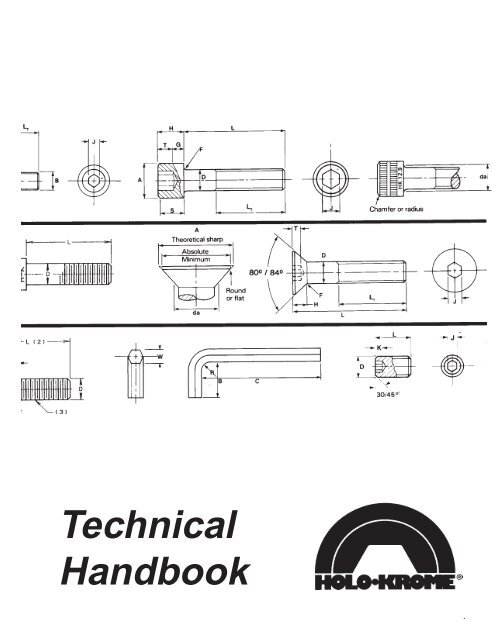
<strong>Tech</strong>nical<br />
Handbook<br />
1
IMPORTANT<br />
<strong>Holo</strong>-<strong>Krome</strong> has published this handbook as a guide to dimensional, mechanical, and application<br />
data for <strong>Holo</strong>-<strong>Krome</strong> Socket Screw Products. However, the following limitations must be carefully<br />
observed in using the information presented in this handbook:<br />
(1) The data in this handbook is subject to change from time to time as a result of changes in<br />
products and specifications. To obtain the latest technical data pertaining to <strong>Holo</strong>-<strong>Krome</strong><br />
products, contact the <strong>Holo</strong>-<strong>Krome</strong> Engineering Department.<br />
(2) Certain products listed in these tables are non-stock products. Specifications of non-stock<br />
products may differ slightly from the handbook description, due to differences in the manufacturing<br />
process.<br />
(3) Proper screw sizes and tightening torque for any given application is a function of the various<br />
design parameters, such as heat, lubrication, etc. Therefore, the data in this handbook<br />
should be used only for general guidance in conjunction with the specific design criteria and<br />
with the application of proper engineering principles.<br />
(4) <strong>Holo</strong>-<strong>Krome</strong> disclaims all responsibility for its products if they are modified in any way, including<br />
plating, hardness alterations, drilling, etc. Specials will be quoted complete by <strong>Holo</strong>-<br />
<strong>Krome</strong> on request.<br />
(5) Appropriate specifications are shown with the applicable products. <strong>Man</strong>y of these are written<br />
by consensus organizations, and, while <strong>Holo</strong>-<strong>Krome</strong> intends that its standard products meet<br />
these specifications in all respects, there are changes which take place over the years and<br />
must be considered not applicable on a retroactive basis.<br />
(6) This handbook has been revised to provide data for Metric module products as well as those<br />
in Inch module. The organization of the book is designed to make it easy for the user to find<br />
his information in whatever module he is working. The Dimensional Data in each case is<br />
presented for the various products, followed by the Application Data. Inch module is presented<br />
complete, followed by the Metric.<br />
The <strong>Holo</strong>-<strong>Krome</strong> Engineering Department welcomes questions regarding fasteners for specific<br />
customer applications. Their technical experience and special test facilities in the precision fasteners<br />
field are available to help solve your fastener problems.<br />
2<br />
i
ii<br />
THE HOLO-KROME QUALITY STORY<br />
Quality is frequently defined as conformance to<br />
specification, and at <strong>Holo</strong>-<strong>Krome</strong> a great deal of effort<br />
is expended in ensuring that the products shipped do,<br />
in fact, meet the required specification.<br />
From the placing of the raw material<br />
order, through the shipping and<br />
certification of the finished product,<br />
<strong>Holo</strong>-<strong>Krome</strong> procedures and<br />
specifications are applied to<br />
meet that objective.<br />
The definition of the required specification requires<br />
a little discussion. <strong>Holo</strong>-<strong>Krome</strong>’s products, like those of<br />
any manufacturer, must meet certain criteria. The<br />
definition of those criteria can be done several ways. It<br />
is common for people to refer to an “Industry Standard,”<br />
when they are looking for an easy way to define<br />
a product. Actually, any manufactured article must, of<br />
necessity, have two sets of characteristics: the dimensional,<br />
controlling the size and shape, and the mechanical,<br />
controlling the base material and the performance<br />
of the product. In the fastener industry, there<br />
are many organizations which write standards or<br />
specifications for this product. In the<br />
case of socket head cap screws, for<br />
instance, one set of applicable<br />
standards would be the ASME/ANSI<br />
B18.3, which defines the dimensional<br />
characteristics of this product, and<br />
ASTM A574, which defines the mechanical properties.<br />
Both of these are quite detailed, providing on the one<br />
hand, basic size definitions such as diameter, length<br />
and thread size, as well as surface finish, concentricity<br />
and method of manufacture, and, on the other hand<br />
the basic chemistry, heat treatment, hardness, tensile<br />
strength and other metallurgical characteristics, as well<br />
as the tests necessary to establish they have been<br />
done correctly.<br />
<strong>Holo</strong>-<strong>Krome</strong>’s specification for raw material has<br />
been designed to provide material which will properly<br />
make the desired product, without inherent flaws that<br />
might be harmful. When the material is received, it is<br />
inspected to be sure that it does meet those specifications,<br />
and then a Lab Number is assigned, which will<br />
provide traceability throughout manufacturing, testing,<br />
storage and shipment.<br />
From the first set-up on the first machine, calibrated<br />
gages and control charts are used to ensure<br />
conformance to the prints which have been assigned,<br />
and at heat treatment, utilizing atmosphere-controlled<br />
furnaces, testing is performed to the further corroborate<br />
adherence to specification. In the case of special<br />
products, the customer may request other specifications<br />
to meet his own particular needs. There are<br />
many specifications in existence for the type of product<br />
we are discussing, and the selection of these specifications<br />
is a matter of agreement between purchaser<br />
and seller. In most cases, the “Industry Standard” is<br />
used, which is the combination shown above, for<br />
socket head cap screws.<br />
The ingredient necessary to provide all of these<br />
assurances lies in <strong>Holo</strong>-<strong>Krome</strong>’s people, who are<br />
trained in the various arts and skills needed to perform<br />
the checks and tests required. In addition to these<br />
people and their skills is the physical plant and equipment<br />
which they use. From indicating thread gages of<br />
the latest type, and laser measuring equipment, to<br />
automated devices to create metallographic specimens,<br />
as well as appropriate testing equipment, the<br />
investment has been made to have available whatever<br />
is required for assurance that the specifications are<br />
being met.<br />
This devotion to quality<br />
is a company philosophy,<br />
from top management to<br />
the last packer on the line.<br />
Quality is everybody’s job,<br />
and every associate in the<br />
<strong>Holo</strong>-<strong>Krome</strong> organization is<br />
aware of that fact, and very<br />
much a part of it. Associate<br />
Involvement Groups are<br />
used in the plant to help<br />
solve problems which are<br />
broader in scope than a<br />
single machine, and these<br />
have proven to be successful<br />
in the drive for continuous<br />
improvement which is<br />
the <strong>Holo</strong>-<strong>Krome</strong> philosophy.<br />
3
4<br />
INCH FASTENERS<br />
III
TABLE OF CONTENTS<br />
DIMENSIONAL DATA Page No.<br />
Socket Head Cap Screws-1960 Series ................................................................................................................... 1-6<br />
Sems for Socket Head Cap Screws ........................................................................................................................ 7-8<br />
Low Head Cap Screws............................................................................................................................................ 9<br />
Flat Countersunk Head Cap Screws ....................................................................................................................... 10,11<br />
Button Head Cap Screws ........................................................................................................................................ 12<br />
Hexagon and Spline Sockets .................................................................................................................................. 13<br />
Socket Head Shoulder Screws ............................................................................................................................... 14,15<br />
Set Screws .............................................................................................................................................................. 16-18<br />
Dowel Pins and Pull Dowel Pins ............................................................................................................................. 19<br />
Allen Wrenches and Bits ......................................................................................................................................... 20<br />
Allen Spline Keys and Bits ...................................................................................................................................... 21<br />
Socket Pressure Plugs-Dryseal-(NPTF)-3/4 Taper ................................................................................................. 22<br />
Socket Pressure Plugs-Flush-(PTF)-7/8 Taper ....................................................................................................... 23<br />
Socket Jam Screws................................................................................................................................................. 24<br />
Allenuts ................................................................................................................................................................... 24<br />
<strong>Holo</strong>-<strong>Krome</strong> Thread Standards and Radius Root Dimensions................................................................................ 25<br />
<strong>Holo</strong>-<strong>Krome</strong> Finishes............................................................................................................................................... 26<br />
Galvanic Corrosion.................................................................................................................................................. 26<br />
Thermal Expansion ................................................................................................................................................. 26<br />
MECHANICAL PROPERTIES AND APPLICATIONS DATA .................................................................................. 27<br />
Mechanical Properties and Applications Data......................................................................................................... 28<br />
Comparison-Socket Screws and Hex Head Screws ............................................................................................... 29<br />
Applications of Various Head Styles ....................................................................................................................... 30<br />
Mechanical Properties-Socket Head Cap Screws-1960 Series .............................................................................. 31<br />
Torque Data-Socket Head Cap Screws-1960 Series.............................................................................................. 32<br />
Decarburization and Discontinuity Limits ................................................................................................................ 33<br />
Mechanical Properties-Stainless Steel Socket Head Cap Screws.......................................................................... 34<br />
Mechanical Properties-Button Head, Flat Countersunk Head, Low Head Cap Screws .......................................... 35<br />
Tightening Torque-Button Head, Flat Countersunk Head, Low Head Cap Screws ................................................ 35<br />
Mechanical Properties-Socket Shoulder Screws .................................................................................................... 36<br />
Socket Set Screws-Alloy Steel-Application Data .................................................................................................... 37<br />
Socket Set Screws-Axial Holding Power................................................................................................................. 38,39<br />
Mechanical Properties-Allen Wrenches and Bits .................................................................................................... 40<br />
Application Data-Socket Pressure Plugs ................................................................................................................ 41<br />
Coated Pressure Plugs ........................................................................................................................................... 42<br />
Mechanical Properties-Dowel Pins ......................................................................................................................... 43<br />
<strong>Holo</strong>-<strong>Krome</strong> Nylok Hex-Socket Screws................................................................................................................... 44,45<br />
Fastener Related Standards ................................................................................................................................... 46,47<br />
General Application Data-Index .............................................................................................................................. 48<br />
Glossary of Terms ................................................................................................................................................... 49,50<br />
Tapping Hints .......................................................................................................................................................... 51<br />
Tap Drill/Hole Sizes................................................................................................................................................. 51<br />
Fastener Joint Design ............................................................................................................................................. 52<br />
Fastener Strengths.................................................................................................................................................. 53<br />
Metric Conversions ................................................................................................................................................. 54<br />
Hardness Value Conversions.................................................................................................................................. 55<br />
Effects of Alloying Elements.................................................................................................................................... 56<br />
Metric Socket Fasteners ......................................................................................................................................... 57<br />
IV<br />
5
6<br />
Inch Section<br />
INDEX TO TABLES<br />
Table 1<br />
Page No.<br />
<strong>Holo</strong>-<strong>Krome</strong> Socket Head Cap Screws-Dimensions 1960 series ..................................................... 1<br />
Table 1A Dimensions of Underhead Fillets ..................................................................................................... 2<br />
Table 2 <strong>Holo</strong>-<strong>Krome</strong> Socket Head Cap Screws- Body and Grip Lengths ..................................................... 3<br />
Table 3 <strong>Holo</strong>-<strong>Krome</strong> Socket Head Cap Screws-Functional Limits for<br />
Runout of Head, Body and Thread ................................................................................................... 4<br />
Table 4 Dimensions for Drilled-Head Socket Screws .................................................................................... 5<br />
Table 5 Drill and Counterbore Sizes - Socket Head Cap Screws-1960 Series ............................................. 6<br />
Table 6 Dimensions of Helical Spring Lock Washers for Socket Head Cap Screw Sems ............................ 7<br />
Table 6A Dimensions of Plain Washers for Sems ........................................................................................... 8<br />
Table 6B Dimensions of Conical Spring Washers for Sems ............................................................................ 8<br />
Table 7 <strong>Holo</strong>-<strong>Krome</strong> Socket Low Head Cap Screws-Dimensions ................................................................. 9<br />
Table 8 <strong>Holo</strong>-<strong>Krome</strong> Socket Flat Countersunk Head Cap Screws-Dimensions ............................................ 10<br />
Table 9 <strong>Holo</strong>-<strong>Krome</strong> Socket Flat Countersunk Head Cap Screws-Body and Grip Lengths .......................... 11<br />
Table 9A <strong>Holo</strong>-<strong>Krome</strong> Socket Flat Countersunk Head Cap Screws-(Beyond sizes in Table 9) ..................... 11<br />
Table 10 <strong>Holo</strong>-<strong>Krome</strong> Socket Button Head Cap Screws-Dimensions ............................................................. 12<br />
Table 11 <strong>Holo</strong>-<strong>Krome</strong> Hexagon and Spline Sockets-Dimensions ................................................................... 13<br />
Table 12 <strong>Holo</strong>-<strong>Krome</strong> Socket Head Shoulder Screws-Dimensions ................................................................ 14<br />
Table 13 <strong>Holo</strong>-<strong>Krome</strong> Socket Set Screws-Dimensions ................................................................................... 16,17<br />
Table 14 <strong>Holo</strong>-<strong>Krome</strong> Socket Set Screws-Key Engagements for Short Length Set Screws .......................... 18<br />
Table 15 <strong>Holo</strong>-<strong>Krome</strong> Dowel Pins-Dimensions ............................................................................................... 19<br />
Table 16 <strong>Holo</strong>-<strong>Krome</strong> Pull Dowel Pins-Dimensions ........................................................................................ 19<br />
Table 17 Allen Wrenches and Bits-Dimensions .............................................................................................. 20<br />
Table 18 Allen Spline Keys and Bits-Dimensions ........................................................................................... 21<br />
Table 19 <strong>Holo</strong>-<strong>Krome</strong> Socket Pressure Plugs-Dryseal (NPTF) Type-3/4 Taper-Dimensions ......................... 22<br />
Table 20 <strong>Holo</strong>-<strong>Krome</strong> Socket Pressure Plugs-Flush (PTF) Type-7/8 Taper-Dimensions ............................... 23<br />
Table 21 <strong>Holo</strong>-<strong>Krome</strong> Socket Jam Screws-Dimensions .................................................................................. 24<br />
Table 22 Allenuts-Dimensions ......................................................................................................................... 24<br />
Table 23 <strong>Holo</strong>-<strong>Krome</strong> Thread Standards ........................................................................................................ 25<br />
Table 24 <strong>Holo</strong>-<strong>Krome</strong> Finishes ........................................................................................................................ 26<br />
Table 24A Galvanic Corrosion ........................................................................................................................... 26<br />
Table 24B Thermal Expansion .......................................................................................................................... 26<br />
Table 25 <strong>Holo</strong>-<strong>Krome</strong> Socket Head Cap Screws Series Mechanical Properties-1960 Series ........................ 31<br />
Table 26 <strong>Holo</strong>-<strong>Krome</strong> Socket Head Cap Screws-Torque Data-1960 Series ................................................... 32<br />
Table 27 Decarburization and Discontinuity Limits ......................................................................................... 33<br />
Table 28 <strong>Holo</strong>-<strong>Krome</strong> Stainless Steel Socket Head Cap Screws ................................................................... 34<br />
Table 29 <strong>Holo</strong>-<strong>Krome</strong> Button, Flat Countersunk Cap Screws-Mechanical Properties & Tightening Torque ... 35<br />
Table 29A <strong>Holo</strong>-<strong>Krome</strong> Low Head Socket Cap Screws-Mechanical Properties & Tightening Torque .............. 35<br />
Table 30 <strong>Holo</strong>-<strong>Krome</strong> Socket Shoulder Screws-Mechanical Properties ......................................................... 36<br />
Table 31 <strong>Holo</strong>-<strong>Krome</strong> Socket Set Screws-Axial Holding Power ...................................................................... 38<br />
Table 32 <strong>Holo</strong>-<strong>Krome</strong> Allen Wrenches and Bits-Mechanical Properties & Application Data ........................... 40<br />
Table 33 <strong>Holo</strong>-<strong>Krome</strong> Pressure Plugs-Application Data ................................................................................. 41<br />
Table 34 <strong>Holo</strong>-<strong>Krome</strong> Dowel Pins-Mechanical Properties .............................................................................. 43<br />
Table 35 Fastener Related Standards ............................................................................................................ 46,47<br />
Table A-1 Common Tap Drill Sizes-Inch & Metric ............................................................................................ 51<br />
Table A-2 Fastener Strengths ........................................................................................................................... 53<br />
Table A-3 Conversion Table-Fractional Inch to Decimal Inch and Millimeter ................................................... 54<br />
Table A-4 Conversion Table-Millimeters to Inches ........................................................................................... 54<br />
Table A-5 Decimal Equivalents-Drill Sizes ........................................................................................................ 54<br />
Table A-6 Hardness Value Conversions ........................................................................................................... 55<br />
V
Intentionally Left Blank<br />
7
TABLE 1 HOLO-KROME SOCKET HEAD CAP SCREWS–1960 SERIES<br />
8<br />
HOLO-KROME<br />
THERMO-FORGED ®<br />
GRAIN FLOW<br />
TABLE 1 DIMENSIONS–1960 SERIES<br />
NOMINAL<br />
SIZE<br />
0<br />
1<br />
2<br />
3<br />
4<br />
5<br />
6<br />
8<br />
10<br />
1/4<br />
5/16<br />
3/8<br />
7/16<br />
1/2<br />
5/8<br />
3/4<br />
7/8<br />
1<br />
1-1/8<br />
1-1/4<br />
1-3/8<br />
1-1/2<br />
1-3/4<br />
2<br />
BASIC<br />
SCREW<br />
DIAMETER<br />
0.0600<br />
0.0730<br />
0.0860<br />
0.0990<br />
0.1120<br />
0.1250<br />
0.1380<br />
0.1640<br />
0.1900<br />
0.2500<br />
0.3125<br />
0.3750<br />
0.4375<br />
0.5000<br />
0.6250<br />
0.7500<br />
0.8750<br />
1.0000<br />
1.1250<br />
1.2500<br />
1.3750<br />
1.5000<br />
1.7500<br />
2.0000<br />
0.096<br />
0.118<br />
0.140<br />
0.161<br />
0.183<br />
0.205<br />
0.226<br />
0.270<br />
0.312<br />
0.375<br />
0.469<br />
0.562<br />
0.656<br />
0.750<br />
0.938<br />
1.125<br />
1.312<br />
1.500<br />
1.688<br />
1.875<br />
2.062<br />
2.250<br />
2.625<br />
3.000<br />
0.091<br />
0.112<br />
0.134<br />
0.154<br />
0.176<br />
0.198<br />
0.218<br />
0.262<br />
0.303<br />
0.365<br />
0.457<br />
0.550<br />
0.642<br />
0.735<br />
0.921<br />
1.107<br />
1.293<br />
1.479<br />
1.665<br />
1.852<br />
2.038<br />
2.224<br />
2.597<br />
2.970<br />
HEAD<br />
SIDE<br />
HEIGHT<br />
NOTES FOR TABLE 1<br />
1. LENGTH. The length of the screw is the distance measured on a line<br />
parallel to the axis, from the plane of the bearing surface under the head<br />
to the plane of the flat of the point. It includes the threads and body. The<br />
basic length dimension on the product shall be the nominal length<br />
expressed as a two-place decimal.<br />
Balance of notes on page 2.<br />
STANDARD LENGTH INCREMENTS, L<br />
NOMINAL<br />
SCREW SIZE<br />
0 to<br />
1 inch<br />
Incl.<br />
Over<br />
1 inch<br />
D(3) A(4)<br />
BODY<br />
DIAMETER<br />
MAX. MIN.<br />
0.0568<br />
0.0695<br />
0.0822<br />
0.0949<br />
0.1075<br />
0.1202<br />
0.1329<br />
0.1585<br />
0.1840<br />
0.2435<br />
0.3053<br />
0.3678<br />
0.4294<br />
0.4919<br />
0.6163<br />
0.7406<br />
0.8647<br />
0.9886<br />
1.1086<br />
1.2336<br />
1.3568<br />
1.4818<br />
1.7295<br />
1.9780<br />
HEAD<br />
DIAMETER<br />
1/8 thru 1/4<br />
1/4 thru 1<br />
1 thru 3-1/2<br />
3-1/2 thru 7<br />
7 thru 10<br />
1 thru 7<br />
7 thru 10<br />
Over 10<br />
MAX. MIN.<br />
NOMINAL<br />
SCREW LENGTH<br />
H<br />
MAX. MIN.<br />
0.060<br />
0.073<br />
0.086<br />
0.099<br />
0.112<br />
0.125<br />
0.138<br />
0.164<br />
0.190<br />
0.250<br />
0.312<br />
0.375<br />
0.438<br />
0.500<br />
0.625<br />
0.750<br />
0.875<br />
1.000<br />
1.125<br />
1.250<br />
1.375<br />
1.500<br />
1.750<br />
HEAD<br />
HEIGHT<br />
1/16<br />
1/8<br />
1/4<br />
1/2<br />
1<br />
1/2<br />
1<br />
2<br />
0.057<br />
0.070<br />
0.083<br />
0.095<br />
0.108<br />
0.121<br />
0.134<br />
0.159<br />
0.185<br />
0.244<br />
0.306<br />
0.368<br />
0.430<br />
0.492<br />
0.616<br />
0.740<br />
0.864<br />
0.988<br />
1.111<br />
1.236<br />
1.360<br />
1.485<br />
1.734<br />
1.983<br />
STANDARD LENGTH<br />
INCREMENT<br />
S M(5) J(5)<br />
SPLINE<br />
SOCKET<br />
SIZE<br />
0.060<br />
0.072<br />
0.096<br />
0.096<br />
0.111<br />
0.111<br />
0.133<br />
0.168<br />
0.183<br />
0.216<br />
0.291<br />
0.372<br />
0.454<br />
0.454<br />
0.595<br />
0.620<br />
0.698<br />
0.790<br />
-<br />
-<br />
-<br />
-<br />
-<br />
-<br />
1/16<br />
5/64<br />
5/64<br />
3/32<br />
3/32<br />
7/64<br />
9/64<br />
5/32<br />
3/16<br />
1/4<br />
5/16<br />
3/8<br />
3/8<br />
1/2<br />
5/8<br />
3/4<br />
3/4<br />
7/8<br />
7/8<br />
HEXAGON<br />
SOCKET<br />
SIZE<br />
MIN. NOM. NOM.<br />
0.054<br />
0.066<br />
0.077<br />
0.089<br />
0.101<br />
0.112<br />
0.124<br />
0.148<br />
0.171<br />
0.225<br />
0.281<br />
0.337<br />
0.394<br />
0.450<br />
0.562<br />
0.675<br />
0.787<br />
0.900<br />
1.012<br />
1.125<br />
1.237<br />
1.350<br />
1.575<br />
1.800<br />
1<br />
1<br />
1-1/4<br />
1-1/2<br />
0.050<br />
0.062<br />
0.078<br />
0.078<br />
0.094<br />
0.094<br />
0.109<br />
0.141<br />
0.156<br />
0.188<br />
0.250<br />
0.312<br />
0.375<br />
0.375<br />
0.500<br />
0.625<br />
0.750<br />
0.750<br />
0.875<br />
0.875<br />
1.000<br />
1.000<br />
1.250<br />
1.500<br />
LENGTH TOLERANCES, L<br />
NOMINAL SCREW SIZE<br />
NOMINAL<br />
SCREW LENGTH<br />
Up to 1., Incl.<br />
Over 1 in. to 2-1/2, Incl.<br />
Over 2-1/2 to 6, Incl.<br />
Over 6<br />
T G K L T(2)<br />
KEY<br />
ENGAGE-<br />
MENT<br />
WALL<br />
THICK-<br />
NESS<br />
MIN. MIN. MAX. MAX. MIN.<br />
0.025<br />
0.031<br />
0.038<br />
0.044<br />
0.051<br />
0.057<br />
0.064<br />
0.077<br />
0.090<br />
0.120<br />
0.151<br />
0.182<br />
0.213<br />
0.245<br />
0.307<br />
0.370<br />
0.432<br />
0.495<br />
0.557<br />
0.620<br />
0.682<br />
0.745<br />
0.870<br />
0.995<br />
0.020<br />
0.025<br />
0.029<br />
0.034<br />
0.038<br />
0.043<br />
0.047<br />
0.056<br />
0.065<br />
0.095<br />
0.119<br />
0.143<br />
0.166<br />
0.190<br />
0.238<br />
0.285<br />
0.333<br />
0.380<br />
0.428<br />
0.475<br />
0.523<br />
0.570<br />
0.665<br />
0.760<br />
0<br />
Thru<br />
3/8,<br />
Incl.<br />
-0.03<br />
-0.04<br />
-0.06<br />
-0.12<br />
CHAMFER<br />
OR<br />
RADIUS<br />
0.003<br />
0.003<br />
0.003<br />
0.003<br />
0.005<br />
0.005<br />
0.005<br />
0.005<br />
0.005<br />
0.008<br />
0.008<br />
0.008<br />
0.010<br />
0.010<br />
0.010<br />
0.010<br />
0.015<br />
0.015<br />
0.015<br />
0.015<br />
0.015<br />
0.015<br />
0.015<br />
0.015<br />
7/16,<br />
Thru<br />
3/4,,<br />
Incl.<br />
TOLERANCE ON LENGTH<br />
-0.03<br />
-0.06<br />
-0.08<br />
-0.12<br />
0.62<br />
0.77<br />
0.80<br />
0.83<br />
0.99<br />
1.00<br />
1.05<br />
1.19<br />
1.27<br />
1.50<br />
1.71<br />
1.94<br />
2.17<br />
2.38<br />
2.82<br />
3.25<br />
3.69<br />
4.12<br />
4.65<br />
5.09<br />
5.65<br />
6.08<br />
7.13<br />
8.11<br />
THREAD<br />
LENGTH<br />
7/8,<br />
Thru<br />
1-1/2,<br />
Incl.<br />
-0.05<br />
-0.10<br />
-0.14<br />
-0.20<br />
0.50<br />
0.62<br />
0.62<br />
0.62<br />
0.75<br />
0.75<br />
0.75<br />
0.88<br />
0.88<br />
1.00<br />
1.12<br />
1.25<br />
1.38<br />
1.50<br />
1.75<br />
2.00<br />
2.25<br />
2.50<br />
2.81<br />
3.12<br />
3.44<br />
3.75<br />
4.38<br />
5.00<br />
Over<br />
1-1/2<br />
-<br />
-0.18<br />
-0.20<br />
-0.24<br />
1
NOTES FOR TABLE 1 CONTINUED<br />
2. THREAD LENGTH. L T Thread length of the screw is the distance from<br />
the extreme point to the last complete or full form thread. See page 3 for<br />
grip and body lengths of standard length screws. L T max. in Table 1 refers<br />
to longer than standard length screws.<br />
3. BODY. L B The unthreaded cylindrical portion of the shank for screws<br />
that are not threaded to the head.<br />
4. HEAD DIAMETER. Heads may be made plain or knurled at <strong>Holo</strong>-<br />
<strong>Krome</strong>'s option unless specified on the order. For knurled screws, the<br />
maximum head diameter includes the knurling. Minimum head diameter<br />
is the diameter of the head before knurling, or any unknurled section or<br />
band on the head.<br />
HEAD CONCENTRICITY. The heads of <strong>Holo</strong>-<strong>Krome</strong> Cap Screws are<br />
concentric with the shank within 1% of the basic screw diameter, D<br />
maximum (2% total runout), or 0.006 inch total runout, whichever is<br />
greater, when held within one diameter of the head but beyond the fillet.<br />
5. SOCKET CONCENTRICITY. <strong>Holo</strong>-<strong>Krome</strong> Sockets are concentric with<br />
the shanks of the cap screws within 1-1/2% of the basic screw diameter,<br />
D maximum, (3% total runout), or 0.005 inch, whichever is greater for<br />
screws through a nominal size of 1/2 inch. Sizes above 1/2 inch have<br />
sockets concentric with the shank within 3% of the basic screw diameter,<br />
D maximum, (6% total runout). See page 13 for socket tolerances.<br />
6. BEARING SURFACE. The plane of the bearing surface is perpendicular<br />
to the axis of the screw within a maximum deviation of 1 degree.<br />
7. THREADS AND GAGING. Threads are Unified Standard radius root.<br />
On screws with a nominal size 0 through 1 inch inclusive, threads are<br />
Class 3A in both UNRC and UNRF. On nominal sizes over 1 inch, threads<br />
are made to Class 2A in both UNRC or UNRF. <strong>Holo</strong>-<strong>Krome</strong> screw threads<br />
have controlled radius roots and radiused runout for greater fatigue life.<br />
Acceptability of screw threads shall be based on System 22 of ANSI/<br />
ASME B1.3M.<br />
Class 3A threads do not provide a plating allowance. When plating is<br />
required, it is recommended that <strong>Holo</strong>-<strong>Krome</strong> supply the parts plated.<br />
8. SCREW POINT CHAMFER. The point shall be flat or slightly concave<br />
and chamfered. The plane of the point shall be approximately normal to<br />
the axis of the screw. The chamfer shall extend slightly below the root of<br />
the thread and the edge between the flat and chamfer may be slightly<br />
rounded. The included angle of the point should be approximately 90<br />
degrees. Chamfering of screw sizes up to and including size 8 (0.164 in.)<br />
shall be optional.<br />
9. FILLET. For all lengths of screws the form of the underhead fillet shall<br />
be optional, as depicted in Figure 1, provided it is a smooth and continuous<br />
concave curve fairing into the bearing surface of the head and the screw<br />
shank within the envelope established by the limits for fillet extension,<br />
length and juncture radius specified in Table 1A.<br />
10. TOTAL RUNOUT. The total runout between the head, body and<br />
threads of socket cap screws shall be such that the screw will assemble<br />
into a compound hole that is threaded at one end to the basic thread size<br />
(Class 3B min.) for a depth equivalent to 1.5 times the basic screw<br />
diameter and drilled and counterbored as shown in Table 3. These<br />
diameters shall be concentric with the axis of the thread within 10% of the<br />
thread pitch diameter tolerance. The starting thread shall be chamfered<br />
and the corners shall be chamfered or rounded to a diameter equal to F<br />
max. Table 1A.<br />
Applicable Standards and Specifications<br />
ASME/ANSI B18.3 and ASTM A574<br />
2<br />
TABLE 1A DIMENSIONS OF UNDERHEAD FILLETS<br />
NOMINAL<br />
SCREW<br />
SIZE<br />
0<br />
1<br />
2<br />
3<br />
4<br />
5<br />
6<br />
8<br />
10<br />
1/4<br />
5/16<br />
3/8<br />
7/16<br />
1/2<br />
5/8<br />
3/4<br />
7/8<br />
1<br />
1-1/8<br />
1-1/4<br />
1-3/8<br />
1-1/2<br />
1-3/4<br />
2<br />
SUPERSEDED DIMENSIONS — 1936 SERIES<br />
The following table is included for reference only.<br />
NOMINAL<br />
SIZE<br />
0<br />
1<br />
2<br />
3<br />
4<br />
5<br />
6<br />
8<br />
10<br />
1/4<br />
5/16<br />
HEAD<br />
DIAMETER<br />
HEXAGON<br />
SOCKET<br />
SIZE<br />
MAX. NOM.<br />
—<br />
—<br />
—<br />
—<br />
—<br />
—<br />
—<br />
—<br />
—<br />
—<br />
7/16<br />
FIGURE 1 UNDERHEAD FILLET DETAIL<br />
B<br />
TRANSITION<br />
DIAMETER<br />
MAX.<br />
0.074<br />
0.087<br />
0.102<br />
0.115<br />
0.130<br />
0.195<br />
0.158<br />
0.188<br />
0.218<br />
0.278<br />
0.347<br />
0.415<br />
0.494<br />
0.552<br />
0.689<br />
0.828<br />
0.963<br />
1.100<br />
1.235<br />
1.370<br />
1.505<br />
1.640<br />
1.910<br />
2.180<br />
—<br />
0.050<br />
1/16<br />
—<br />
5/64<br />
—<br />
3/32<br />
1/8<br />
—<br />
—<br />
7/32<br />
NOMINAL<br />
SIZE<br />
3/8<br />
7/16<br />
1/2<br />
5/8<br />
3/4<br />
7/8<br />
1<br />
1-1/8<br />
1-1/4<br />
1-3/8<br />
1-1/2<br />
R E<br />
JUNCTURE<br />
RADIUS<br />
MIN.<br />
0.002<br />
0.003<br />
0.003<br />
0.004<br />
0.004<br />
0.005<br />
0.005<br />
0.006<br />
0.006<br />
0.007<br />
0.009<br />
0.012<br />
0.014<br />
0.016<br />
0.021<br />
0.025<br />
0.031<br />
0.034<br />
0.039<br />
0.044<br />
0.048<br />
0.052<br />
0.062<br />
0.071<br />
HEAD<br />
DIAMETER<br />
MAX.<br />
—<br />
5/8<br />
—<br />
7/8<br />
1<br />
1-1/8<br />
1-5/16<br />
1-1/2<br />
1-3/4<br />
1-7/8<br />
2<br />
FILLET<br />
LENGTH<br />
MAX.<br />
0.012<br />
0.012<br />
0.014<br />
0.014<br />
0.015<br />
0.017<br />
0.017<br />
0.020<br />
0.024<br />
0.024<br />
0.029<br />
0.034<br />
0.039<br />
0.044<br />
0.054<br />
0.066<br />
0.075<br />
0.085<br />
0.094<br />
0.102<br />
0.110<br />
0.119<br />
0.136<br />
0.153<br />
HEXAGON<br />
SOCKET<br />
SIZE<br />
NOM.<br />
—<br />
5/16<br />
—<br />
—<br />
9/16<br />
9/16<br />
5/8<br />
3/4<br />
3/4<br />
3/4<br />
—<br />
9
TABLE 2 HOLO-KROME SOCKET HEAD CAP SCREWS - 1960 SERIES<br />
GRIP LENGTH — L G . The maximum distance from the bearing surface<br />
of the head to the first completed or full form thread. A clamped part thinner<br />
than L G would not allow the screw to seat.<br />
BODY LENGTH — L B. The minimum length of the unthreaded cylindrical<br />
portion of the shank.<br />
TABLE 2 BODY AND GRIP LENGTHS - 1960 SERIES - LENGTHS ABOVE LINE ARE THREADED TO THE HEAD<br />
NOMINAL<br />
SIZE<br />
NOMINAL<br />
LENGTH<br />
3/4<br />
7/8<br />
1<br />
1-1/4<br />
1-1/2<br />
1-3/4<br />
2<br />
2-1/4<br />
2-1/2<br />
2-3/4<br />
3<br />
3-1/4<br />
3-1/2<br />
3-3/4<br />
4<br />
NOMINAL<br />
SIZE<br />
NOMINAL<br />
LENGTH<br />
1-1/2<br />
1-3/4<br />
2<br />
2-1/4<br />
2-1/2<br />
2-3/4<br />
3<br />
3-1/4<br />
3-1/2<br />
3-3/4<br />
4<br />
4-1/4<br />
4-1/2<br />
4-3/4<br />
5<br />
5-1/4<br />
5-1/2<br />
5-3/4<br />
6<br />
6-1/4<br />
6-1/2<br />
6-3/4<br />
7<br />
7-1/4<br />
7-1/2<br />
7-3/4<br />
8<br />
8-1/2<br />
9<br />
9-1/2<br />
10<br />
11<br />
12<br />
13<br />
14<br />
15<br />
16<br />
17<br />
18<br />
19<br />
20<br />
1/4 5/16<br />
3/8 7/16 1/2 5/8 3/4 7/8 1.000<br />
L G L B L G L B L G L B L G L B L G L B L G L B L G L B L G L B L G L B<br />
.50<br />
.50<br />
1.00<br />
1.00<br />
1.50<br />
1.50<br />
2.00<br />
2.00<br />
2.50<br />
2.50<br />
3.00<br />
3.00<br />
3.50<br />
3.50<br />
4.00<br />
—<br />
—<br />
—<br />
—<br />
—<br />
—<br />
—<br />
—<br />
—<br />
—<br />
—<br />
—<br />
—<br />
—<br />
—<br />
—<br />
—<br />
—<br />
—<br />
—<br />
—<br />
—<br />
—<br />
—<br />
—<br />
—<br />
0 1 2 3 4 5 6 8 10<br />
L G L B L G L B L G L B L G L B L G L B L G L B L G L B L G L B L G L B<br />
.25<br />
.25<br />
.50<br />
.75<br />
—<br />
—<br />
—<br />
—<br />
—<br />
—<br />
—<br />
—<br />
—<br />
—<br />
—<br />
.19<br />
.19<br />
.44<br />
.69<br />
—<br />
—<br />
—<br />
—<br />
—<br />
—<br />
—<br />
—<br />
—<br />
—<br />
—<br />
.25<br />
.25<br />
.75<br />
.75<br />
1.25<br />
1.25<br />
1.75<br />
1.75<br />
2.25<br />
2.25<br />
2.75<br />
2.75<br />
3.25<br />
3.25<br />
3.75<br />
—<br />
—<br />
—<br />
—<br />
—<br />
—<br />
—<br />
—<br />
—<br />
—<br />
—<br />
—<br />
—<br />
—<br />
—<br />
—<br />
—<br />
—<br />
—<br />
—<br />
—<br />
—<br />
—<br />
—<br />
—<br />
—<br />
.25<br />
.25<br />
.62<br />
.88<br />
—<br />
—<br />
—<br />
—<br />
—<br />
—<br />
—<br />
—<br />
—<br />
—<br />
.62<br />
.62<br />
1.12<br />
1.12<br />
1.62<br />
1.62<br />
2.12<br />
2.12<br />
2.62<br />
2.62<br />
3.12<br />
3.12<br />
3.62<br />
3.62<br />
4.12<br />
4.12<br />
4.62<br />
4.62<br />
5.12<br />
—<br />
—<br />
—<br />
—<br />
—<br />
—<br />
—<br />
—<br />
—<br />
—<br />
—<br />
—<br />
—<br />
—<br />
—<br />
—<br />
—<br />
—<br />
—<br />
—<br />
—<br />
.17<br />
.17<br />
.55<br />
.80<br />
—<br />
—<br />
—<br />
—<br />
—<br />
—<br />
—<br />
—<br />
—<br />
—<br />
.35<br />
.35<br />
.85<br />
.85<br />
1.35<br />
1.35<br />
1.85<br />
1.85<br />
2.35<br />
2.35<br />
2.85<br />
2.85<br />
3.35<br />
3.35<br />
3.85<br />
3.85<br />
4.35<br />
4.35<br />
4.85<br />
—<br />
—<br />
—<br />
—<br />
—<br />
—<br />
—<br />
—<br />
—<br />
—<br />
—<br />
—<br />
—<br />
—<br />
—<br />
—<br />
—<br />
—<br />
—<br />
—<br />
—<br />
.25<br />
.25<br />
.62<br />
.88<br />
1.12<br />
—<br />
—<br />
—<br />
—<br />
—<br />
—<br />
—<br />
—<br />
—<br />
.50<br />
.50<br />
1.00<br />
1.00<br />
1.50<br />
1.50<br />
2.00<br />
2.00<br />
2.50<br />
2.50<br />
3.00<br />
3.00<br />
3.50<br />
3.50<br />
4.00<br />
4.00<br />
4.50<br />
4.50<br />
5.00<br />
5.00<br />
5.50<br />
5.50<br />
6.00<br />
6.00<br />
—<br />
—<br />
—<br />
—<br />
—<br />
—<br />
—<br />
—<br />
—<br />
—<br />
—<br />
—<br />
—<br />
—<br />
—<br />
—<br />
For longer lengths or diameters over 1" see Page 1 L , Table 1<br />
T<br />
10<br />
.16<br />
.16<br />
.54<br />
.79<br />
1.04<br />
—<br />
—<br />
—<br />
—<br />
—<br />
—<br />
—<br />
—<br />
—<br />
.19<br />
.19<br />
.69<br />
.69<br />
1.19<br />
1.19<br />
1.69<br />
1.69<br />
2.19<br />
2.19<br />
2.69<br />
2.69<br />
3.19<br />
3.19<br />
3.69<br />
3.69<br />
4.19<br />
4.19<br />
4.69<br />
4.69<br />
5.19<br />
5.19<br />
5.69<br />
5.69<br />
—<br />
—<br />
—<br />
—<br />
—<br />
—<br />
—<br />
—<br />
—<br />
—<br />
—<br />
—<br />
—<br />
—<br />
—<br />
—<br />
.25<br />
.25<br />
.62<br />
.88<br />
1.12<br />
1.38<br />
—<br />
—<br />
—<br />
—<br />
—<br />
—<br />
—<br />
—<br />
.62<br />
.62<br />
1.12<br />
1.12<br />
1.62<br />
1.62<br />
2.12<br />
2.12<br />
2.62<br />
2.62<br />
3.12<br />
3.12<br />
3.62<br />
3.62<br />
4.12<br />
4.12<br />
4.62<br />
4.62<br />
5.12<br />
5.12<br />
5.62<br />
5.62<br />
6.12<br />
6.12<br />
6.62<br />
7.12<br />
7.62<br />
—<br />
—<br />
—<br />
—<br />
—<br />
—<br />
—<br />
—<br />
—<br />
—<br />
—<br />
—<br />
.15<br />
.15<br />
.52<br />
.77<br />
1.02<br />
1.27<br />
—<br />
—<br />
—<br />
—<br />
—<br />
—<br />
—<br />
—<br />
.27<br />
.27<br />
.77<br />
.77<br />
1.27<br />
1.27<br />
1.77<br />
1.77<br />
2.27<br />
2.27<br />
2.77<br />
2.77<br />
3.27<br />
3.27<br />
3.77<br />
3.77<br />
4.27<br />
4.27<br />
4.77<br />
4.77<br />
5.27<br />
5.27<br />
5.77<br />
5.77<br />
6.27<br />
6.77<br />
7.27<br />
—<br />
—<br />
—<br />
—<br />
—<br />
—<br />
—<br />
—<br />
—<br />
—<br />
—<br />
—<br />
.25<br />
.25<br />
.75<br />
.75<br />
1.25<br />
1.25<br />
—<br />
—<br />
—<br />
—<br />
—<br />
—<br />
—<br />
.75<br />
.75<br />
.75<br />
1.50<br />
1.50<br />
1.50<br />
2.25<br />
2.25<br />
2.25<br />
3.00<br />
3.00<br />
3.00<br />
3.75<br />
3.75<br />
3.75<br />
4.50<br />
4.50<br />
4.50<br />
5.25<br />
5.25<br />
5.25<br />
6.00<br />
6.00<br />
6.00<br />
7.00<br />
7.00<br />
8.00<br />
8.00<br />
—<br />
—<br />
—<br />
—<br />
—<br />
—<br />
—<br />
—<br />
—<br />
—<br />
.12<br />
.12<br />
.62<br />
.62<br />
1.12<br />
1.12<br />
—<br />
—<br />
—<br />
—<br />
—<br />
—<br />
—<br />
.36<br />
.36<br />
.36<br />
1.12<br />
1.12<br />
1.12<br />
1.86<br />
1.86<br />
1.86<br />
2.62<br />
2.62<br />
2.62<br />
3.36<br />
3.36<br />
3.36<br />
4.12<br />
4.12<br />
4.12<br />
4.86<br />
4.86<br />
4.86<br />
5.62<br />
5.62<br />
5.62<br />
6.62<br />
6.62<br />
7.62<br />
7.62<br />
—<br />
—<br />
—<br />
—<br />
—<br />
—<br />
—<br />
—<br />
—<br />
—<br />
.25<br />
.25<br />
.75<br />
.75<br />
1.25<br />
1.25<br />
1.75<br />
—<br />
—<br />
—<br />
—<br />
—<br />
—<br />
.75<br />
.75<br />
.75<br />
1.50<br />
1.50<br />
1.50<br />
2.25<br />
2.25<br />
2.25<br />
3.00<br />
3.00<br />
3.00<br />
3.75<br />
3.75<br />
3.75<br />
4.50<br />
4.50<br />
4.50<br />
5.25<br />
5.25<br />
5.25<br />
6.00<br />
6.00<br />
6.75<br />
6.75<br />
7.75<br />
7.75<br />
9.25<br />
10.25<br />
—<br />
—<br />
—<br />
—<br />
—<br />
—<br />
—<br />
—<br />
.12<br />
.12<br />
.62<br />
.62<br />
1.12<br />
1.12<br />
1.62<br />
—<br />
—<br />
—<br />
—<br />
—<br />
—<br />
.30<br />
.30<br />
.30<br />
1.04<br />
1.04<br />
1.04<br />
1.80<br />
1.80<br />
1.80<br />
2.54<br />
2.54<br />
2.54<br />
3.30<br />
3.30<br />
3.30<br />
4.04<br />
4.04<br />
4.04<br />
4.80<br />
4.80<br />
4.80<br />
5.54<br />
5.54<br />
6.30<br />
6.30<br />
7.30<br />
7.30<br />
8.80<br />
9.80<br />
—<br />
—<br />
—<br />
—<br />
—<br />
—<br />
—<br />
—<br />
.50<br />
.50<br />
1.00<br />
1.00<br />
1.50<br />
1.50<br />
2.00<br />
—<br />
—<br />
—<br />
—<br />
—<br />
1.00<br />
1.00<br />
1.00<br />
1.00<br />
2.00<br />
2.00<br />
2.00<br />
2.00<br />
3.00<br />
3.00<br />
3.00<br />
3.00<br />
4.00<br />
4.00<br />
4.00<br />
4.00<br />
5.00<br />
5.00<br />
5.00<br />
5.00<br />
6.00<br />
6.00<br />
7.00<br />
7.00<br />
8.00<br />
9.00<br />
10.00<br />
11.00<br />
12.00<br />
13.00<br />
—<br />
—<br />
—<br />
—<br />
—<br />
.34<br />
.34<br />
.84<br />
.84<br />
1.34<br />
1.34<br />
1.84<br />
—<br />
—<br />
—<br />
—<br />
—<br />
.50<br />
.50<br />
.50<br />
.50<br />
1.50<br />
1.50<br />
1.50<br />
1.50<br />
2.50<br />
2.50<br />
2.50<br />
2.50<br />
3.50<br />
3.50<br />
3.50<br />
3.50<br />
4.50<br />
4.50<br />
4.50<br />
4.50<br />
5.50<br />
5.50<br />
6.50<br />
6.50<br />
7.50<br />
8.50<br />
9.50<br />
10.50<br />
11.50<br />
12.50<br />
—<br />
—<br />
—<br />
—<br />
—<br />
.38<br />
.38<br />
.88<br />
.88<br />
1.38<br />
1.38<br />
1.88<br />
1.88<br />
2.38<br />
—<br />
—<br />
—<br />
1.00<br />
1.00<br />
1.00<br />
1.00<br />
2.00<br />
2.00<br />
2.00<br />
2.00<br />
3.00<br />
3.00<br />
3.00<br />
3.00<br />
4.00<br />
4.00<br />
4.00<br />
4.00<br />
5.00<br />
5.00<br />
5.00<br />
5.00<br />
6.00<br />
6.00<br />
7.00<br />
7.00<br />
8.00<br />
9.00<br />
10.00<br />
11.00<br />
12.00<br />
13.00<br />
14.00<br />
15.00<br />
—<br />
—<br />
.22<br />
.22<br />
.72<br />
.72<br />
1.22<br />
1.22<br />
1.72<br />
1.72<br />
2.22<br />
—<br />
—<br />
—<br />
.44<br />
.44<br />
.44<br />
.44<br />
1.44<br />
1.44<br />
1.44<br />
1.44<br />
2.44<br />
2.44<br />
2.44<br />
2.44<br />
3.44<br />
3.44<br />
3.44<br />
3.44<br />
4.44<br />
4.44<br />
4.44<br />
4.44<br />
5.44<br />
5.44<br />
6.44<br />
6.44<br />
7.44<br />
8.44<br />
9.44<br />
10.44<br />
11.44<br />
12.44<br />
13.44<br />
14.44<br />
—<br />
—<br />
.38<br />
.38<br />
.88<br />
.88<br />
1.38<br />
1.38<br />
1.88<br />
1.88<br />
2.38<br />
2.38<br />
2.88<br />
2.88<br />
1.00<br />
1.00<br />
1.00<br />
1.00<br />
2.00<br />
2.00<br />
2.00<br />
2.00<br />
3.00<br />
3.00<br />
3.00<br />
3.00<br />
4.00<br />
4.00<br />
4.00<br />
4.00<br />
5.00<br />
5.00<br />
5.00<br />
6.00<br />
6.00<br />
7.00<br />
7.00<br />
8.00<br />
9.00<br />
10.00<br />
11.00<br />
12.00<br />
13.00<br />
14.00<br />
15.00<br />
16.00<br />
17.00<br />
.17<br />
.17<br />
.67<br />
.67<br />
1.17<br />
1.17<br />
1.67<br />
1.67<br />
2.17<br />
2.17<br />
2.67<br />
2.67<br />
.38<br />
.38<br />
.38<br />
.38<br />
1.38<br />
1.38<br />
1.38<br />
1.38<br />
2.38<br />
2.38<br />
2.38<br />
2.38<br />
3.38<br />
3.38<br />
3.38<br />
3.38<br />
4.38<br />
4.38<br />
4.38<br />
5.38<br />
5.38<br />
6.38<br />
6.38<br />
7.38<br />
8.38<br />
9.38<br />
10.38<br />
11.38<br />
12.38<br />
13.38<br />
14.38<br />
15.38<br />
16.38<br />
3
TABLE 9 HOLO-KROME SOCKET FLAT COUNTERSUNK HEAD CAP SCREWS<br />
TABLE 9 BODY AND GRIP LENGTHS<br />
NOMINAL SIZE<br />
NOMINAL LENGTH<br />
3/4<br />
7/8<br />
1<br />
1-1/4<br />
1-1/2<br />
1-3/4<br />
2<br />
2-1/4<br />
2-1/2<br />
2-3/4<br />
3<br />
3-1/4<br />
3-1/2<br />
3-3/4<br />
4<br />
NOMINAL SIZE<br />
NOMINAL LENGTH<br />
1-3/4<br />
2<br />
2-1/4<br />
2-1/2<br />
2-3/4<br />
3<br />
3-1/4<br />
3-1/2<br />
3-3/4<br />
4<br />
4-1/4<br />
4-1/2<br />
4-3/4<br />
5<br />
5-1/4<br />
5-1/2<br />
5-3/4<br />
6<br />
0 1<br />
2 3 4 5 6 8 10<br />
LGH LBH LGH LBH LGH LBH LGH LBH LGH LBH LGH LBH LGH LBH LGH LBH LGH LBH 0.25<br />
0.25<br />
0.50<br />
0.75<br />
—<br />
—<br />
—<br />
—<br />
—<br />
—<br />
—<br />
—<br />
—<br />
—<br />
—<br />
0.19<br />
0.19<br />
0.44<br />
0.69<br />
—<br />
—<br />
—<br />
—<br />
—<br />
—<br />
—<br />
—<br />
—<br />
—<br />
—<br />
0.25<br />
0.25<br />
0.62<br />
0.88<br />
—<br />
—<br />
—<br />
—<br />
—<br />
—<br />
—<br />
—<br />
—<br />
—<br />
0.17<br />
0.17<br />
0.55<br />
0.80<br />
—<br />
—<br />
—<br />
—<br />
—<br />
—<br />
—<br />
—<br />
—<br />
—<br />
0.25<br />
0.25<br />
0.62<br />
0.88<br />
1.12<br />
—<br />
—<br />
—<br />
—<br />
—<br />
—<br />
—<br />
—<br />
—<br />
0.16<br />
0.16<br />
0.54<br />
0.79<br />
1.04<br />
—<br />
—<br />
—<br />
—<br />
—<br />
—<br />
—<br />
—<br />
—<br />
0.25<br />
0.25<br />
0.62<br />
0.88<br />
1.12<br />
1.38<br />
—<br />
—<br />
—<br />
—<br />
—<br />
—<br />
—<br />
—<br />
0.15<br />
0.15<br />
0.52<br />
0.77<br />
1.02<br />
1.27<br />
—<br />
—<br />
—<br />
—<br />
—<br />
—<br />
—<br />
—<br />
0<br />
1<br />
2<br />
3<br />
4<br />
5<br />
6<br />
8<br />
0.50<br />
0.50<br />
1.00<br />
1.00<br />
1.50<br />
—<br />
—<br />
—<br />
—<br />
—<br />
—<br />
—<br />
1/4 5/16<br />
3/8 7/16 1/2 5/8 3/4 7/8 1<br />
LGH LBH LGH LBH LGH LBH LGH LBH LGH LBH LGH LBH LGH LBH LGH LBH LGH LBH 0.75<br />
0.75<br />
1.25<br />
1.25<br />
1.75<br />
1.75<br />
2.25<br />
2.25<br />
2.75<br />
2.75<br />
3.25<br />
3.25<br />
3.75<br />
3.75<br />
4.25<br />
—<br />
—<br />
—<br />
0.50<br />
0.50<br />
1.00<br />
1.00<br />
1.50<br />
1.50<br />
2.00<br />
2.00<br />
2.50<br />
2.50<br />
3.00<br />
3.00<br />
3.50<br />
3.50<br />
4.00<br />
—<br />
—<br />
—<br />
NOTES FOR TABLES 9 AND 9A<br />
0.88<br />
0.88<br />
1.38<br />
1.38<br />
1.88<br />
1.88<br />
2.38<br />
2.38<br />
2.88<br />
2.88<br />
3.38<br />
3.38<br />
3.88<br />
3.88<br />
4.38<br />
4.38<br />
4.88<br />
0.60<br />
0.60<br />
1.10<br />
1.10<br />
1.60<br />
1.60<br />
2.10<br />
2.10<br />
2.60<br />
2.60<br />
3.10<br />
3.10<br />
3.60<br />
3.60<br />
4.10<br />
4.10<br />
4.60<br />
1.00<br />
1.00<br />
1.50<br />
1.50<br />
2.00<br />
2.00<br />
2.50<br />
2.50<br />
3.00<br />
3.00<br />
3.50<br />
3.50<br />
4.00<br />
4.00<br />
4.50<br />
4.50<br />
0.69<br />
0.69<br />
1.19<br />
1.19<br />
1.69<br />
1.69<br />
2.19<br />
2.19<br />
2.69<br />
2.69<br />
3.19<br />
3.19<br />
3.69<br />
3.69<br />
4.19<br />
4.19<br />
1.12<br />
1.12<br />
1.62<br />
1.62<br />
2.12<br />
2.12<br />
2.62<br />
2.62<br />
3.12<br />
3.12<br />
3.62<br />
3.62<br />
4.12<br />
4.12<br />
4.62<br />
1. GRIP GAGING LENGTH, L GH . The grip gaging length is the distance,<br />
measured parallel to the axis of screw, from the top of the head to the first<br />
complete (full form) thread under the head.<br />
2. BODY LENGTH L BH . The body length is the length, measured parallel<br />
to axis of screw, of the unthreaded portion of the shank and the head<br />
height.<br />
3. CONCENTRICITY. Concentricity of the thread with the body shall be<br />
within 0.005 in. per inch of body length (unthreaded portion) full (total)<br />
indicator reading, taken directly under the head when the screw is held by<br />
the full threads closest to the head of the screw and shall not exceed 0.025<br />
in.<br />
4. For screws of nominal lengths longer than those shown in Table 10, and<br />
for screws over 1 in. in diameter, the L GH max. and L BH min. shall be<br />
determined as shown in Table 10A: L GH = (L-L T ), L BH = (L-L TT ).<br />
0.77<br />
0.77<br />
1.27<br />
1.27<br />
1.77<br />
1.77<br />
2.27<br />
2.27<br />
2.77<br />
2.77<br />
3.27<br />
3.27<br />
3.77<br />
3.77<br />
4.27<br />
1.00<br />
1.00<br />
1.00<br />
1.75<br />
1.75<br />
1.75<br />
2.50<br />
2.50<br />
2.50<br />
3.25<br />
3.25<br />
3.25<br />
4.00<br />
4.00<br />
4.00<br />
NOMINAL<br />
SIZE<br />
OR BASIC<br />
SCREW<br />
DIAMETER<br />
10<br />
1/4<br />
5/16<br />
3/8<br />
0.38<br />
0.38<br />
0.88<br />
0.88<br />
1.38<br />
—<br />
—<br />
—<br />
—<br />
—<br />
—<br />
—<br />
0.62<br />
0.62<br />
0.62<br />
1.36<br />
1.36<br />
1.36<br />
2.12<br />
2.12<br />
2.12<br />
2.86<br />
2.86<br />
2.86<br />
3.62<br />
3.62<br />
3.62<br />
0.50<br />
0.50<br />
1.00<br />
1.00<br />
1.50<br />
—<br />
—<br />
—<br />
—<br />
—<br />
—<br />
—<br />
1.50<br />
1.50<br />
1.50<br />
2.25<br />
2.25<br />
2.25<br />
3.00<br />
3.00<br />
3.00<br />
3.75<br />
3.75<br />
3.75<br />
L T<br />
THREAD<br />
LENGTH<br />
L TT<br />
TOTAL<br />
THREAD<br />
LENGTH<br />
MIN. MAX.<br />
0.50<br />
0.62<br />
0.62<br />
0.62<br />
0.75<br />
0.75<br />
0.75<br />
0.88<br />
0.88<br />
1.00<br />
1.12<br />
1.25<br />
0.38<br />
0.38<br />
0.88<br />
0.88<br />
1.38<br />
—<br />
—<br />
—<br />
—<br />
—<br />
—<br />
—<br />
1.04<br />
1.04<br />
1.04<br />
1.80<br />
1.80<br />
1.80<br />
2.54<br />
2.54<br />
2.54<br />
3.30<br />
3.30<br />
3.30<br />
0.62<br />
0.77<br />
0.80<br />
0.83<br />
0.99<br />
1.00<br />
1.05<br />
1.19<br />
1.27<br />
1.50<br />
1.71<br />
1.94<br />
0.50<br />
0.50<br />
1.00<br />
1.00<br />
1.50<br />
1.50<br />
2.00<br />
—<br />
—<br />
—<br />
—<br />
—<br />
1.50<br />
1.50<br />
1.50<br />
1.50<br />
2.50<br />
2.50<br />
2.50<br />
2.50<br />
3.50<br />
3.50<br />
3.50<br />
0.34<br />
0.34<br />
0.84<br />
0.84<br />
1.34<br />
1.34<br />
1.84<br />
—<br />
—<br />
—<br />
—<br />
—<br />
1.00<br />
1.00<br />
1.00<br />
1.00<br />
2.00<br />
2.00<br />
2.00<br />
2.00<br />
3.00<br />
3.00<br />
3.00<br />
NOMINAL<br />
SIZE<br />
OR BASIC<br />
SCREW<br />
DIAMETER<br />
0.38<br />
0.38<br />
0.88<br />
0.88<br />
1.38<br />
1.38<br />
1.88<br />
1.88<br />
2.38<br />
—<br />
—<br />
—<br />
1.50<br />
1.50<br />
1.50<br />
1.50<br />
2.50<br />
2.50<br />
2.50<br />
2.50<br />
3.50<br />
3.50<br />
0.22<br />
0.22<br />
0.72<br />
0.72<br />
1.22<br />
1.22<br />
1.72<br />
1.72<br />
2.22<br />
—<br />
—<br />
—<br />
0.94<br />
0.94<br />
0.94<br />
0.94<br />
1.94<br />
1.94<br />
1.94<br />
1.94<br />
2.94<br />
2.94<br />
L T<br />
THREAD<br />
LENGTH<br />
L TT<br />
TOTAL<br />
THREAD<br />
LENGTH<br />
MIN. MAX.<br />
1.38<br />
1.50<br />
1.75<br />
2.00<br />
2.25<br />
2.50<br />
0.62<br />
0.62<br />
1.12<br />
1.12<br />
1.62<br />
1.62<br />
2.12<br />
2.12<br />
2.62<br />
2.62<br />
3.12<br />
1.50<br />
1.50<br />
1.50<br />
1.50<br />
2.50<br />
2.50<br />
2.50<br />
2.50<br />
3.50<br />
TABLE 9A (For Screws Beyond Sizes in Table 9)<br />
0.0600<br />
0.0730<br />
0.0860<br />
0.0990<br />
0.1120<br />
0.1250<br />
0.1380<br />
0.1640<br />
0.1900<br />
0.2500<br />
0.3125<br />
0.3750<br />
7/16<br />
1/2<br />
5/8<br />
3/4<br />
7/8<br />
1<br />
0.4375<br />
0.5000<br />
0.6250<br />
0.7500<br />
0.8750<br />
1.0000<br />
2.17<br />
2.38<br />
2.82<br />
3.25<br />
3.69<br />
4.12<br />
0.42<br />
0.42<br />
0.92<br />
0.92<br />
1.42<br />
1.42<br />
1.92<br />
1.92<br />
2.42<br />
2.42<br />
2.92<br />
0.88<br />
0.88<br />
0.88<br />
0.88<br />
1.88<br />
1.88<br />
1.88<br />
1.88<br />
2.88<br />
11
TABLE 10 HOLO-KROME SOCKET BUTTON HEAD CAP SCREWS<br />
NOTE: THIS PRODUCT IS DESIGNED<br />
FOR LIGHT FASTENING APPLICA-<br />
TIONS ONLY, SUCH AS SHEETMETAL<br />
COVERS, PLASTIC GUARDS, ETC. IT<br />
SHOULD NOT BE USED IN CRITICAL<br />
HIGH STRENGTH APPLICATIONS<br />
WHERE SOCKET HEAD CAPSCREWS<br />
SHOULD BE USED.<br />
TABLE 10 DIMENSIONS<br />
NOMINAL<br />
SIZE<br />
0<br />
1<br />
2<br />
3<br />
4<br />
5<br />
6<br />
8<br />
10<br />
1/4<br />
5/16<br />
3/8<br />
1/2<br />
5/8<br />
BASIC<br />
SCREW<br />
DIAMETER<br />
0.0600<br />
0.0730<br />
0.0860<br />
0.0990<br />
0.1120<br />
0.1250<br />
0.1380<br />
0.1640<br />
0.1900<br />
0.2500<br />
0.3125<br />
0.3750<br />
0.5000<br />
0.6250<br />
MAX.<br />
0.114<br />
0.139<br />
0.164<br />
0.188<br />
0.213<br />
0.238<br />
0.262<br />
0.312<br />
0.361<br />
0.437<br />
0.547<br />
0.656<br />
0.875<br />
1.000<br />
0.104<br />
0.129<br />
0.154<br />
0.176<br />
0.201<br />
0.226<br />
0.250<br />
0.298<br />
0.347<br />
0.419<br />
0.527<br />
0.636<br />
0.851<br />
0.970<br />
NOTES FOR TABLE 10<br />
1. THREAD LENGTH. On all stock lengths the last complete (full form)<br />
thread measured with a thread ring gage (having the thread chamfer and/<br />
or counterbore removed) extends to within two threads of the head. On<br />
other lengths and diameters the length of thread will conform to Socket<br />
Head Cap Screw thread lengths.<br />
2. SCREW LENGTH. The length of the screw is the distance measured<br />
on a line parallel to the axis, from the plane of the bearing surface under<br />
the head to the plane of the flat of the point. The basic length dimension<br />
on the product shall be the nominal length expressed as a two-place<br />
decimal.<br />
3. THREADS AND GAGING. Threads are Class 3A UNRC and UNRF<br />
with <strong>Holo</strong>-<strong>Krome</strong> controlled radium root and radiused runout. Acceptability<br />
of screw threads shall be based on System 22 of ANSI/ASME B1.3M.<br />
Class 3A threads do not provide a plating allowance. When plating is<br />
required, it is recommended that <strong>Holo</strong>-<strong>Krome</strong> supply the parts plated.<br />
Applicable Standards and Specifications<br />
ASME/ANSI B18.3 and ASTM F835<br />
12<br />
A H S<br />
HEAD<br />
DIAMETER<br />
STANDARD LENGTH INCREMENTS, L<br />
MIN.<br />
MAX.<br />
0.032<br />
0.039<br />
0.046<br />
0.052<br />
0.059<br />
0.066<br />
0.073<br />
0.087<br />
0.101<br />
0.132<br />
0.166<br />
0.199<br />
0.265<br />
0.331<br />
HEAD<br />
DIAMETER<br />
MIN.<br />
0.026<br />
0.033<br />
0.038<br />
0.044<br />
0.051<br />
0.058<br />
0.063<br />
0.077<br />
0.091<br />
0.122<br />
0.152<br />
0.185<br />
0.245<br />
0.311<br />
Nominal Screw Length Standard Length Increment<br />
1/8 thru 1/4 1/16<br />
1/4 thru 1 1/8<br />
1 thru 2 1/4<br />
LENGTH TOLERANCES<br />
0 thru 3/8, 1/2 and 5/8,<br />
Nominal Screw Size Inclusive Inclusive<br />
Nominal Screw Length Tolerance on Length<br />
Up to 1 in., Inc. -0.03 -0.03<br />
Over 1 in. to 2-1/2, Incl. -0.04 -0.06<br />
HEAD<br />
SIDE<br />
HEIGHT<br />
REF.<br />
0.010<br />
0.010<br />
0.010<br />
0.010<br />
0.015<br />
0.015<br />
0.015<br />
0.015<br />
0.020<br />
0.031<br />
0.031<br />
0.031<br />
0.046<br />
0.062<br />
M<br />
SPLINE<br />
SOCKET<br />
SIZE<br />
0.035<br />
0.050<br />
0.050<br />
1/16 0.062<br />
1/16<br />
5/64<br />
5/64<br />
3/32<br />
1/8<br />
5/32<br />
3/16<br />
7/32<br />
5/16<br />
3/8<br />
J<br />
HEXAGON<br />
SOCKET<br />
SIZE<br />
T F<br />
KEY<br />
ENGAGE-<br />
MENT<br />
0.020<br />
0.028<br />
0.028<br />
0.035<br />
0.035<br />
0.044<br />
0.044<br />
0.052<br />
0.070<br />
0.087<br />
0.105<br />
0.122<br />
0.175<br />
0.210<br />
FILLET<br />
EXTENSION<br />
NOM. NOM. MIN. MAX. MIN.<br />
0.048<br />
0.060<br />
0.060<br />
0.072<br />
0.072<br />
0.096<br />
0.096<br />
0.111<br />
0.145<br />
0.183<br />
0.216<br />
0.251<br />
0.372<br />
0.454<br />
0.062<br />
0.078<br />
0.078<br />
0.094<br />
0.125<br />
0.156<br />
0.188<br />
0.219<br />
0.312<br />
0.375<br />
0.010<br />
0.010<br />
0.010<br />
0.010<br />
0.010<br />
0.010<br />
0.010<br />
0.015<br />
0.015<br />
0.020<br />
0.020<br />
0.020<br />
0.030<br />
0.030<br />
0.005<br />
0.005<br />
0.005<br />
0.005<br />
0.005<br />
0.005<br />
0.005<br />
0.010<br />
0.010<br />
0.015<br />
0.015<br />
0.015<br />
0.020<br />
0.020<br />
L<br />
MAXIMUM<br />
STANDARD<br />
LENGTH<br />
NOM.<br />
1/2<br />
1/2<br />
1/2<br />
1/2<br />
1/2<br />
1/2<br />
5/8<br />
3/4<br />
1<br />
1<br />
1<br />
1-1/4<br />
4. SOCKETS. Thermo forging ® , a <strong>Holo</strong>-<strong>Krome</strong> patented process, provides<br />
accurately formed sockets without broaching chips. Because<br />
Thermo-Forging is not a machining process, it does not shear metal<br />
grains and sockets can be deeper and much stronger.<br />
5. FILLET. For all lengths of screws, the form of the filet shall be optional,<br />
provided it fairs into the bearing surface within the limits of the thread<br />
major diameter maximum plus F maximum, and the thread major diameter<br />
minimum, plus F minimum and is smooth and continuous curve<br />
having a bearing surface juncture radius no less than that tabulated<br />
below:<br />
Nominal<br />
Screw<br />
Size<br />
0<br />
1<br />
2<br />
3<br />
4<br />
5<br />
6<br />
8<br />
Juncture<br />
Radius<br />
Min.<br />
.002<br />
.003<br />
.003<br />
.004<br />
.004<br />
.005<br />
.005<br />
.006<br />
Nominal<br />
Screw<br />
Size<br />
10<br />
1/4<br />
5/16<br />
3/8<br />
1/2<br />
5/8<br />
2<br />
2<br />
Juncture<br />
Radius<br />
Min.<br />
.006<br />
.007<br />
.009<br />
.012<br />
.016<br />
.021<br />
6. BEARING SURFACE. The plane of the bearing surface shall be<br />
perpendicular to the axis of the shank within 2°.
TABLE 11 HOLO-KROME HEXAGON AND SPLINE SOCKETS<br />
TABLE 11 DIMENSIONS<br />
HEXAGON<br />
NOMINAL<br />
SOCKET<br />
SIZE<br />
0.028<br />
0.035<br />
0.050<br />
1/16<br />
5/64<br />
5/32<br />
7/64<br />
1/8<br />
9/64<br />
5/32<br />
3/16<br />
7/32<br />
1/4<br />
5/16<br />
3/8<br />
7/16<br />
1/2<br />
9/16<br />
5/8<br />
3/4<br />
7/8<br />
1<br />
1-1/4<br />
J<br />
SOCKET WIDTH<br />
ACROSS FLATS<br />
MAX. MIN.<br />
0.0285<br />
0.0355<br />
0.0510<br />
0.0635<br />
0.0791<br />
0.0952<br />
0.1111<br />
0.1270<br />
0.1426<br />
0.1587<br />
0.1900<br />
0.2217<br />
0.2530<br />
0.3160<br />
0.3790<br />
0.4420<br />
0.5050<br />
0.5080<br />
0.6310<br />
0.7570<br />
0.8850<br />
1.0100<br />
1.2650<br />
0.0280<br />
0.0350<br />
0.0500<br />
0.0625<br />
0.0781<br />
0.0937<br />
0.1094<br />
0.1250<br />
0.1406<br />
0.1562<br />
0.1875<br />
0.2187<br />
0.2500<br />
0.3125<br />
0.3750<br />
0.4375<br />
0.5000<br />
0.5625<br />
0.6250<br />
0.7500<br />
0.8750<br />
1.0000<br />
1.2500<br />
SPLINE<br />
NOMINAL<br />
SOCKET<br />
AND KEY<br />
SIZE<br />
0.033<br />
0.048<br />
0.060<br />
0.072<br />
0.096<br />
0.111<br />
0.133<br />
0.145<br />
0.168<br />
0.183<br />
0.216<br />
0.251<br />
0.291<br />
0.372<br />
0.454<br />
0.595<br />
0.620<br />
0.698<br />
0.790<br />
NOTES FOR TABLE 11<br />
1. SOCKET DEPTH (T) - Applicable socket depths are specified in the<br />
dimensional tables and notes for the respective screw types.<br />
NUMBER<br />
OF<br />
TEETH<br />
4<br />
6<br />
6<br />
6<br />
6<br />
6<br />
6<br />
6<br />
6<br />
6<br />
6<br />
6<br />
6<br />
6<br />
6<br />
6<br />
6<br />
6<br />
6<br />
MAX.<br />
0.035<br />
0.050<br />
0.062<br />
0.074<br />
0.098<br />
0.115<br />
0.137<br />
0.149<br />
0.173<br />
0.188<br />
0.221<br />
0.256<br />
0.298<br />
0.380<br />
0.463<br />
0.604<br />
0.631<br />
0.709<br />
0.801<br />
M<br />
SOCKET MAJOR<br />
DIAMETER<br />
MIN.<br />
0.034<br />
0.049<br />
0.061<br />
0.073<br />
0.097<br />
0.113<br />
0.135<br />
0.147<br />
0.171<br />
0.186<br />
0.219<br />
0.254<br />
0.296<br />
0.377<br />
0.460<br />
0.601<br />
0.627<br />
0.705<br />
0.797<br />
N<br />
SOCKET MINOR<br />
DIAMETER<br />
MAX. MIN.<br />
0.026<br />
0.041<br />
0.051<br />
0.064<br />
0.082<br />
0.098<br />
0.118<br />
0.128<br />
0.150<br />
0.163<br />
0.190<br />
0.221<br />
0.254<br />
0.319<br />
0.386<br />
0.509<br />
0.535<br />
0.604<br />
0.685<br />
0.0255<br />
0.040<br />
0.050<br />
0.063<br />
0.080<br />
0.096<br />
0.116<br />
0.126<br />
0.147<br />
0.161<br />
0.188<br />
0.219<br />
0.252<br />
0.316<br />
0.383<br />
0.506<br />
0.531<br />
0.600<br />
0.681<br />
P<br />
WIDTH OF<br />
TOOTH<br />
MAX. MIN.<br />
0.012<br />
0.011<br />
0.014<br />
0.016<br />
0.022<br />
0.025<br />
0.030<br />
0.032<br />
0.036<br />
0.039<br />
0.050<br />
0.060<br />
0.068<br />
0.092<br />
0.112<br />
0.138<br />
0.149<br />
0.168<br />
0.189<br />
0.0115<br />
0.010<br />
0.013<br />
0.015<br />
0.021<br />
0.023<br />
0.028<br />
0.030<br />
0.033<br />
0.037<br />
0.048<br />
0.058<br />
0.066<br />
0.089<br />
0.109<br />
0.134<br />
0.145<br />
0.164<br />
0.185<br />
NOTE: Sockets up to 1" in nominal size should not be evaluated by direct measurement, but checked with go<br />
and no-go gages as specified in ASME/ANSI B18.3.<br />
2. SOCKET CHAMFER. Where hexagon sockets are chamfered, the depth of<br />
chamfer shall not exceed 10 per cent of the nominal socket size for sizes up to<br />
and including 1/16 in., and 7.5 per cent for larger sizes. For chamfered sockets, it<br />
is permissible for the NOT GO socket gage to enter to the dept of chamfer as<br />
specified in ASME/ANSI B 18.3.<br />
13
14<br />
TABLE 12 HOLO-KROME SOCKET HEAD SHOULDER SCREWS<br />
TABLE 12 DIMENSIONS<br />
NOMINAL SIZE<br />
OR BASIC<br />
SHOULDER<br />
DIAMETER<br />
D(1) A H S J T M<br />
SHOULDER<br />
DIAMETER<br />
1/4 0.250 0.2480 0.2460 0.375 0.357 0.188 0.177 0.157 1/8 0.125 0.094 0.014 0.009<br />
5/16 0.312 0.3105 0.3085 0.438 0.419 0.219 0.209 0.183 5/32 0.156 0.117 0.017 0.012<br />
3/8 0.375 0.3730 0.3710 0.562 0.543 0.250 0.240 0.209 3/16 0.188 0.141 0.020 0.015<br />
1/2 0.500 0.4980 0.4960 0.750 0.729 0.312 0.302 0.262 1/4 0.250 0.188 0.026 0.020<br />
5/8 0.625 0.6230 0.6210 0.875 0.853 0.375 0.365 0.315 5/16 0.312 0.234 0.032 0.024<br />
3/4 0.750 0.7480 0.7460 1.000 0.977 0.500 0.490 0.421 3/8 0.375 0.281 0.039 0.030<br />
1 1.000 0.9980 0.9960 1.312 1.287 0.625 0.610 0.527 1/2 0.500 0.375 0.050 0.040<br />
1-1/4 1.250 1.2480 1.2460 1.750 1.723 0.750 0.735 0.633 5/8 0.625 0.469 0.060 0.050<br />
1-1/2 1.500 1.4980 1.4960 2.125 2.095 1.000 0.980 0.842 7/8 0.875 0.656 0.070 0.060<br />
1-3/4 1.750 1.7480 1.7460 2.375 2.345 1.125 1.105 0.948 1 1.000 0.750 0.080 0.070<br />
2 2.000 1.9980 1.9960 2.750 2.720 1.250 1.230 1.054 1-1/4 1.250 0.937 0.090 0.080<br />
TABLE 12 DIMENSIONS (continued)<br />
NOMINAL SIZE<br />
OR BASIC<br />
SHOULDER<br />
DIAMETER<br />
MAX. MIN. MAX. MIN. MAX. MIN. MIN. NOM. MIN. MAX. MIN.<br />
SHOULDER<br />
NECK<br />
DIAMETER<br />
HEAD<br />
DIAMETER<br />
NOMINAL THREAD<br />
SIZE OR BASIC<br />
THREAD DIAMETER<br />
HEAD<br />
SIDE HEIGHT<br />
HEAD<br />
HEIGHT<br />
HEXAGON<br />
SOCKET SIZE<br />
KEY<br />
ENGAGEMENT<br />
HEAD FILLET<br />
EXTENSION ABOVE D<br />
K F D T G I N E(3)<br />
SHOULDER<br />
NECK<br />
WIDTH<br />
THREADS<br />
PER<br />
INCH<br />
THREAD<br />
NECK<br />
DIAMETER<br />
THREAD<br />
NECK<br />
WIDTH<br />
THREAD<br />
NECK<br />
FILLET<br />
THREAD<br />
LENGTH<br />
MIN. MAX. MAX. MIN. MAX MAX. MIN. BASIC<br />
1/4 0.250 0.227 0.093 10 0.1900 24 0.142 0.133 0.083 0.023 0.017 0.375<br />
5/16 0.312 0.289 0.093 1/4 0.2500 20 0.193 0.182 0.100 0.028 0.022 0.438<br />
3/8 0.375 0.352 0.093 5/16 0.3125 18 0.249 0.237 0.111 0.031 0.025 0.500<br />
1/2 0.500 0.477 0.093 3/8 0.3750 16 0.304 0.291 0.125 0.035 0.029 0.625<br />
5/8 0.625 0.602 0.093 1/2 0.5000 13 0.414 0.397 0.154 0.042 0.036 0.750<br />
3/4 0.750 0.727 0.093 5/8 0.6250 11 0.521 0.502 0.182 0.051 0.045 0.875<br />
1 1.000 0.977 0.125 3/4 0.7500 10 0.638 0.616 0.200 0.055 0.049 1.000<br />
1-1/4 1.250 1.227 0.125 7/8 0.8750 9 0.750 0.726 0.222 0.062 0.056 1.125<br />
1-1/2 1.500 1.478 0.125 1-1/8 1.1250 7 0.964 0.934 0.286 0.072 0.066 1.500<br />
1-3/4 1.750 1.728 0.125 1-1/4 1.2500 7 1.089 1.059 0.286 0.072 0.066 1.750<br />
2 2.000 1.978 0.125 1-1/2 1.5000 6 1.307 1.277 0.333 0.102 0.096 2.000
HOLO-KROME SOCKET HEAD SHOULDER SCREWS<br />
NOTES FOR TABLE 12<br />
1. SHOULDER. Shoulder refers to the enlarged unthreaded portion of<br />
the screw, the diameter of which serves as the basis for derivation of<br />
the nominal size. The maximum shoulder diameter is 0.002 less than<br />
the nominal size.<br />
2. LENGTH. The length of screw shall be measured parallel to the axis<br />
of screw from the plane of the bearing surface under the head to the<br />
plane of the shoulder at threaded end. The basic length dimension of<br />
the product shall be the nominal length of the shoulder, expressed as a<br />
three-place decimal.<br />
STANDARD LENGTHS. The difference between consecutive lengths of<br />
standard screws shall be as designated in the following tabulation:<br />
Nominal Screw<br />
(Shoulder) Length<br />
1/4 thru 3/4<br />
3/4 thru 5<br />
Over 5<br />
Standard Length<br />
Increment<br />
1/8<br />
1/4<br />
1/2<br />
3. THREAD LENGTH TOLERANCE. The tolerance on thread length E<br />
shall be -0.020 in. for screw sizes up to 3/8 in. inclusive, and -0.030 in.<br />
for screw sizes larger than 3/8 in.<br />
4. NECK AND FILLET UNDER HEAD. The screws may be necked<br />
under the head at option of <strong>Holo</strong>-<strong>Krome</strong>. The fillet at the intersection of<br />
the head bearing surface and neck or shoulder shall be above D within<br />
the tabulated limits for M.<br />
5. NECK UNDER SHOULDER. The neck under the shoulder shall<br />
allow the shoulder to seat against the face of a standard basic GO<br />
thread ring gage.<br />
6. BEARING SURFACE. The plane of the bearing surface of the head<br />
shall be perpendicular to the axis of the shoulder within a maximum<br />
deviation of two degrees.<br />
7. CONCENTRICITY. Head shall be concentric with the shoulder<br />
within 1 per cent (2 per cent total runout) of the nominal diameter D or<br />
0.003 in. (0.006 in. total runout), whichever is greater.<br />
Pitch diameter and shoulder shall be concentric within 0.004 in.<br />
total runout when checked at a distance of 0.188 in. from the shoulder<br />
at the threaded end.<br />
Concentricity, parallelism, bow and squareness of shoulder to<br />
thread, shall be within 0.005 in. total runout per inch of shoulder length,<br />
with a maximum of 0.025 in., when firmly seated against the shoulder in<br />
a threaded bushing, and checked on the shoulder a distance 2F from<br />
the underside of the head. Threads of bushing shall be basic size, and<br />
bushing OD and ends shall be concentric and square with the axis.<br />
8. THREADS AND GAGING. Threads are Class 3A UNRC and UNRF<br />
with <strong>Holo</strong>-<strong>Krome</strong> controlled radius root. Acceptability of screw threads<br />
shall be based on System 22 of ANSI/ASME B1.3M.<br />
Class 3A threads do not provide a plating allowance. When<br />
plating is required, it is recommended that <strong>Holo</strong>-<strong>Krome</strong> supply the parts<br />
plated.<br />
Applicable Standards and Specifications<br />
ASME/ANSI B18.3<br />
15
TABLE 13 HOLO-KROME SOCKET SET SCREWS<br />
TABLE 13 DIMENSIONS<br />
NOMINAL<br />
SIZE<br />
16<br />
0<br />
1<br />
2<br />
3<br />
4<br />
5<br />
6<br />
8<br />
10<br />
1/4<br />
5/16<br />
3/8<br />
7/16<br />
1/2<br />
5/8<br />
3/4<br />
7/8<br />
1<br />
BASIC<br />
SCREW<br />
DIAMETER<br />
0.0600<br />
0.0730<br />
0.0860<br />
0.0990<br />
0.1120<br />
0.1250<br />
0.1380<br />
0.1640<br />
0.1900<br />
0.2500<br />
0.3125<br />
0.3750<br />
0.4375<br />
0.5000<br />
0.6250<br />
0.7500<br />
0.8750<br />
1.0000<br />
1/16<br />
1/16<br />
5/64<br />
3/32<br />
1/8<br />
5/32<br />
3/16<br />
7/32<br />
1/4<br />
5/16<br />
3/8<br />
1/2<br />
9/16<br />
J(4)<br />
HEXAGON<br />
SOCKET<br />
SIZE<br />
NOM.<br />
0.028<br />
0.035<br />
0.035<br />
0.050<br />
0.050<br />
0.062<br />
0.062<br />
0.078<br />
0.094<br />
0.125<br />
0.156<br />
0.188<br />
0.219<br />
0.250<br />
0.312<br />
0.375<br />
0.500<br />
0.562<br />
M(4) T (3)<br />
R<br />
MIN KEY ENGAGEMENT<br />
TO DEVELOP FUNCTIONAL<br />
SPLINE<br />
SOCKET<br />
CAPABILITY OF KEY<br />
CUP<br />
POINT<br />
FLAT<br />
POINT<br />
SIZE<br />
HEX SPLINE<br />
DIAMETERS<br />
DIAMETERS<br />
SOCKET SOCKET<br />
NOM. T MIN. H T MIN. S MAX. MIN. MAX. MIN.<br />
0.050<br />
0.060<br />
0.060<br />
0.070<br />
0.070<br />
0.080<br />
0.080<br />
0.090<br />
0.100<br />
0.125<br />
0.156<br />
0.188<br />
0.219<br />
0.250<br />
0.312<br />
0.375<br />
0.500<br />
0.562<br />
NOTES FOR TABLE 13<br />
1. LENGTH - The length of the screw shall be measured overall, parallel<br />
to axis of screw. The basic length dimension on the product shall be the<br />
nominal length expressed as a two-place decimal.<br />
STANDARD LENGTH INCREMENTS, L<br />
0.033<br />
0.033<br />
0.048<br />
0.048<br />
0.060<br />
0.072<br />
0.072<br />
0.096<br />
0.111<br />
0.145<br />
0.183<br />
0.216<br />
0.251<br />
0.291<br />
0.372<br />
0.454<br />
0.595<br />
–<br />
NOMINAL SCREW LENGTH STANDARD LENGTH INCREMENT<br />
1/16 thru 3/16* .03<br />
1/8 thru 1/2 .06<br />
1/2 thru 1 .12<br />
1 thru 2 .25<br />
2 thru 6 .50<br />
Over 6 1.00<br />
* Applicable only to sizes 0 (0.060 in.) through 3 (0.099 in.), inclusive.<br />
LENGTH TOLERANCES, L<br />
NOMINAL SCREW LENGTH TOLERANCE ON LENGTH<br />
Up to 5/8, Incl.. ± 0.01<br />
Over 5/8 to 2, Incl. ± 0.02<br />
Over 2 to 6, Incl. ± 0.03<br />
Over 6 ± 0.06<br />
0.026<br />
0.035<br />
0.040<br />
0.040<br />
0.045<br />
0.055<br />
0.055<br />
0.080<br />
0.080<br />
0.125<br />
0.156<br />
0.188<br />
0.219<br />
0.250<br />
0.312<br />
0.375<br />
0.500<br />
–<br />
0.032<br />
0.038<br />
0.043<br />
0.050<br />
0.056<br />
0.062<br />
0.069<br />
0.082<br />
0.095<br />
0.125<br />
0.156<br />
0.187<br />
0.218<br />
0.250<br />
0.312<br />
0.375<br />
0.437<br />
0.500<br />
C 1<br />
0.027<br />
0.033<br />
0.038<br />
0.045<br />
0.051<br />
0.056<br />
0.062<br />
0.074<br />
0.086<br />
0.114<br />
0.144<br />
0.174<br />
0.204<br />
0.235<br />
0.295<br />
0.357<br />
0.418<br />
0.480<br />
0.033<br />
0.040<br />
0.047<br />
0.054<br />
0.061<br />
0.067<br />
0.074<br />
0.087<br />
0.102<br />
0.132<br />
0.172<br />
0.212<br />
0.252<br />
0.291<br />
0.371<br />
0.450<br />
0.530<br />
0.609<br />
C 2<br />
0.027<br />
0.033<br />
0.039<br />
0.045<br />
0.051<br />
0.057<br />
0.064<br />
0.076<br />
0.088<br />
0.118<br />
0.156<br />
0.194<br />
0.232<br />
0.270<br />
0.347<br />
0.425<br />
0.502<br />
0.579<br />
OVAL<br />
POINT<br />
RADIUS<br />
BASIC<br />
0.045<br />
0.055<br />
0.064<br />
0.074<br />
0.084<br />
0.094<br />
0.104<br />
0.123<br />
0.142<br />
0.188<br />
0.234<br />
0.281<br />
0.328<br />
0.375<br />
0.469<br />
0.562<br />
0.656<br />
0.750<br />
Y<br />
CONE POINT ANGLE<br />
90° ±2°<br />
FOR THESE NOMINAL<br />
LENGTHS OR LONGER:<br />
118° ±2°<br />
FOR SHORTER<br />
NOMINAL LENGTHS<br />
0.09<br />
0.09<br />
0.13<br />
0.13<br />
0.19<br />
0.19<br />
0.19<br />
0.25<br />
0.25<br />
0.31<br />
0.38<br />
0.44<br />
0.50<br />
0.57<br />
0.75<br />
0.88<br />
1.00<br />
1.13<br />
2. THREADS AND GAGING. Threads shall be Unified external thread;<br />
Class 3A, UNC and UNF Series. Acceptability of screw threads shall<br />
based on System 22 of ANSI/ASME B1.3M.<br />
Since standard gages provide only for engagement lengths up to 1-<br />
1/2 diameters, changes in pitch diameter of either or both external and<br />
internal thread may be required for longer lengths of engagement.<br />
Class 3A does not provide a plating allowance. When plated<br />
products are required, it is recommended that <strong>Holo</strong>-<strong>Krome</strong> supply the<br />
parts plated.<br />
3. SOCKET DEPTHS. The key engagement dimensions given in columns<br />
T H and T S of Table 13 shall apply only to nominal screw lengths equal to<br />
or longer than the lengths listed in Columns B and B 1 , respectively. For<br />
hexagon socket key engagement dimensions in screws of shorter nominal<br />
lengths than listed in Column B of Table 13, see Table 14. Spline sockets<br />
in screws shorter than those listed in Column B 1 of Table 13 shall be as<br />
deep as practicable.<br />
4. SOCKETS. Thermo-Forging ® , a <strong>Holo</strong>-<strong>Krome</strong> patented process, provides<br />
accurately formed sockets without broaching chips. Because<br />
Thermo-Forging is not a machining process, it does not shear metal grains<br />
and the sockets can be deeper and much stronger.
HOLO-KROME SOCKET SET SCREWS<br />
TABLE 13 DIMENSIONS (Continued)<br />
NOMINAL<br />
SIZE<br />
0<br />
1<br />
2<br />
3<br />
4<br />
5<br />
6<br />
8<br />
10<br />
1/4<br />
5/16<br />
3/8<br />
7/16<br />
1/2<br />
5/8<br />
3/4<br />
7/8<br />
1<br />
BASIC<br />
SCREW<br />
DIAMETER<br />
0.0600<br />
0.0730<br />
0.0860<br />
0.0990<br />
0.1120<br />
0.1250<br />
0.1380<br />
0.1640<br />
0.1900<br />
0.2500<br />
0.3125<br />
0.3750<br />
0.4375<br />
0.5000<br />
0.6250<br />
0.7500<br />
0.8750<br />
1.0000<br />
P Q<br />
DIAMETER<br />
MAX. MIN.<br />
0.040<br />
0.049<br />
0.057<br />
0.066<br />
0.075<br />
0.083<br />
0.092<br />
0.109<br />
0.127<br />
0.156<br />
0.203<br />
0.250<br />
0.297<br />
0.344<br />
0.469<br />
0.562<br />
0.656<br />
0.750<br />
HALF DOG POINT<br />
0.037<br />
0.045<br />
0.053<br />
0.062<br />
0.070<br />
0.078<br />
0.087<br />
0.103<br />
0.120<br />
0.149<br />
0.195<br />
0.241<br />
0.287<br />
0.334<br />
0.456<br />
0.549<br />
0.642<br />
0.734<br />
LENGTH<br />
MAX. MIN.<br />
0.017<br />
0.021<br />
0.024<br />
0.027<br />
0.030<br />
0.033<br />
0.038<br />
0.043<br />
0.049<br />
0.067<br />
0.082<br />
0.099<br />
0.114<br />
0.130<br />
0.164<br />
0.196<br />
0.227<br />
0.260<br />
0.013<br />
0.017<br />
0.020<br />
0.023<br />
0.026<br />
0.027<br />
0.032<br />
0.037<br />
0.041<br />
0.059<br />
0.074<br />
0.089<br />
0.104<br />
0.120<br />
0.148<br />
0.180<br />
0.211<br />
0.240<br />
5. CHAMFER. On screws longer than minimum lengths listed in<br />
Column B or B 1 , the face will normally be chamfered between 30° and<br />
45°. Shorter screws will be chamfered where possible.<br />
In special applications where stripping is a problem, <strong>Holo</strong>-<strong>Krome</strong><br />
may be able to supply unchamfered screws to provide additional<br />
stength.<br />
6. POINT ANGLE. The angle on flat and cup point set screws is 45° plus<br />
5° minus 0° for screws of lengths equal to or longer than those listed in<br />
Column B or B 1 ; and 30° minimum for shorter screws.<br />
The point angle applies only to that portion of the angle below the<br />
thread root diameter.<br />
7. OVAL POINT. The oval point radius tolerance is + 0.015 inches for<br />
B<br />
SHORTEST OPTIMUM NOMINAL LENGTH<br />
TO WHICH COLUMN T APPLIES<br />
H<br />
CUP AND<br />
FLAT POINTS<br />
0.13<br />
0.13<br />
0.13<br />
0.19<br />
0.19<br />
0.19<br />
0.19<br />
0.19<br />
0.19<br />
0.25<br />
0.31<br />
0.38<br />
0.44<br />
0.50<br />
0.63<br />
0.75<br />
0.88<br />
1.00<br />
90° CONE AND<br />
OVAL POINTS<br />
0.13<br />
0.19<br />
0.19<br />
0.19<br />
0.19<br />
0.19<br />
0.25<br />
0.25<br />
0.25<br />
0.31<br />
0.44<br />
0.44<br />
0.63<br />
0.63<br />
0.88<br />
1.00<br />
1.00<br />
1.25<br />
HALF DOG<br />
POINTS<br />
0.13<br />
0.13<br />
0.19<br />
0.19<br />
0.19<br />
0.19<br />
0.19<br />
0.25<br />
0.25<br />
0.31<br />
0.38<br />
0.44<br />
0.50<br />
0.63<br />
0.88<br />
1.00<br />
1.00<br />
1.25<br />
CUP AND<br />
FLAT POINTS<br />
nominal sizes through 5, and + 0.031 inches for screws 6 and over.<br />
8. HALF DOG POINT ECCENTRICITY. The permissible eccentricity<br />
of the half dog axis, with respect to the axis of the thread, shall not<br />
exceed 3 per cent of the basic diameter of the screw, and in no case shall<br />
be greater than 0.005 in. for sizes up to and incl. 3/4 in. For sizes over<br />
3/4 in. it shall not be greater than 0.010 in. (Total runout shall not exceed<br />
twice the permissible eccentricity.)<br />
9. CONE POINT CONFIGURATION. The apex of the cone may be<br />
flattened or rounded to the extent of 10 per cent of the basic diameter<br />
of the screw.<br />
Applicable Standards and Specifications<br />
ASME/ANSI B18.3 and ASTM F912.<br />
B 1<br />
SHORTEST OPTIMUM NOMINAL LENGTH<br />
TO WHICH COLUMN T S APPLIES<br />
0.06<br />
0.13<br />
0.13<br />
0.13<br />
0.13<br />
0.13<br />
0.13<br />
0.19<br />
0.19<br />
0.25<br />
0.31<br />
0.38<br />
0.44<br />
0.50<br />
0.63<br />
0.75<br />
0.88<br />
–<br />
90°. CONE AND<br />
OVAL POINTS<br />
0.13<br />
0.19<br />
0.19<br />
0.19<br />
0.19<br />
0.19<br />
0.25<br />
0.25<br />
0.25<br />
0.31<br />
0.44<br />
0.44<br />
0.63<br />
0.63<br />
0.88<br />
1.00<br />
1.25<br />
–<br />
HALF DOG<br />
POINTS<br />
0.13<br />
0.13<br />
0.19<br />
0.19<br />
0.19<br />
0.19<br />
0.19<br />
0.25<br />
0.25<br />
0.31<br />
0.38<br />
0.44<br />
0.50<br />
0.63<br />
0.88<br />
1.00<br />
1.00<br />
–<br />
17
TABLE 14 HOLO-KROME SOCKET SET SCREWS<br />
TABLE 14 HEXAGON KEY ENGAGEMENTS FOR SHORT LENGTH SET SCREWS<br />
1 CAUTION: The use of products listed in Table 14 can result in failure of the socket key, or mating threads during tightening because key engagement<br />
and thread length are less than optimum. Therefore, it is strongly recommended that screws of lengths equal to or greater than the lengths specified<br />
in Columns B and B 1 of Table 13 be used wherever possible.<br />
2 See Table 13 and the illustrations and notes thereto, for additional dimensions and specifications.<br />
3 These products are covered in Table 13.<br />
4 These sizes are impractical to manufacture because of point configuration and short length.<br />
5 Cone point angle for these lengths shall be 90°; see Column Y in Table 13.<br />
6 Cup angle may be 118° or 130°, ± 5°, depending upon screw length and manufacturing process.<br />
18<br />
NOMINAL<br />
SIZE<br />
0<br />
1<br />
2<br />
3<br />
4<br />
5<br />
6<br />
8<br />
10<br />
1/4<br />
5/16<br />
3/8<br />
7/16<br />
1/2<br />
5/8<br />
3/4<br />
7/8<br />
1<br />
BASIC<br />
SCREW<br />
DIAMETER<br />
0.0600<br />
0.0730<br />
0.0860<br />
0.0990<br />
0.1120<br />
0.1250<br />
0.1380<br />
0.1640<br />
0.1900<br />
0.2500<br />
0.3125<br />
0.3750<br />
0.4375<br />
0.5000<br />
0.6250<br />
0.7500<br />
0.8750<br />
1.0000<br />
1/16<br />
1/16<br />
5/64<br />
3/32<br />
1/8<br />
5/32<br />
3/16<br />
7/32<br />
1/4<br />
5/16<br />
3/8<br />
1/2<br />
9/16<br />
J L<br />
HEXAGON<br />
SOCKET SIZE<br />
NOM.<br />
0.028<br />
0.035<br />
0.035<br />
0.050<br />
0.050<br />
0.062<br />
0.062<br />
0.078<br />
0.094<br />
0.125<br />
0.156<br />
0.188<br />
0.219<br />
0.250<br />
0.312<br />
0.375<br />
0.500<br />
0.562<br />
NOMINAL<br />
SCREW<br />
LENGTHS 1<br />
0.06<br />
0.09<br />
0.06<br />
0.09<br />
0.06<br />
0.09<br />
0.09<br />
0.13<br />
0.09<br />
0.13<br />
0.09<br />
0.13<br />
0.09<br />
0.13<br />
0.16<br />
0.13<br />
0.16<br />
0.19<br />
0.13<br />
0.19<br />
0.19<br />
0.25<br />
0.25<br />
0.31<br />
0.25<br />
0.31<br />
0.50<br />
0.38<br />
0.44<br />
0.38<br />
0.44<br />
0.50<br />
0.50<br />
0.63<br />
0.75<br />
0.75<br />
0.87<br />
0.75<br />
0.85<br />
1.00<br />
CUP 6 AND<br />
FLAT POINTS<br />
0.030<br />
0.040<br />
0.030<br />
0.040<br />
0.030<br />
0.040<br />
0.040<br />
0.055<br />
0.045<br />
0.060<br />
0.040<br />
0.060<br />
0.040<br />
0.060<br />
0.070<br />
0.060<br />
0.070<br />
— 3<br />
0.060<br />
— 3<br />
0.090<br />
— 3<br />
0.125<br />
— 3<br />
0.110<br />
0.140<br />
— 3<br />
0.160<br />
— 3<br />
0.175<br />
0.215<br />
— 3<br />
0.205<br />
0.255<br />
— 3<br />
0.330<br />
— 3<br />
0.280<br />
0.380<br />
— 3<br />
1, 2<br />
T H<br />
MINIMUM KEY ENGAGEMENT<br />
118° CONE AND<br />
OVAL POINTS<br />
0.028<br />
0.040 5<br />
0.029<br />
0.040 5<br />
0.029<br />
0.040<br />
0.039<br />
0.040 5<br />
0.039<br />
0.045<br />
0.039<br />
0.045<br />
0.039<br />
0.045<br />
0.065<br />
0.050<br />
0.060<br />
0.065<br />
0.042<br />
0.060<br />
0.065<br />
0.110<br />
0.099<br />
0.140<br />
0.090<br />
0.115<br />
0.165<br />
0.125<br />
0.160<br />
0.130<br />
0.155<br />
0.195<br />
0.145<br />
0.190<br />
0.325<br />
0.255<br />
0.419<br />
0.175<br />
0.280<br />
0.380<br />
HALF DOG POINT<br />
— 4<br />
0.028<br />
— 4<br />
0.040<br />
— 4<br />
0.035<br />
— 4<br />
0.045<br />
— 4<br />
0.045<br />
— 4<br />
0.045<br />
— 4<br />
0.045<br />
0.065<br />
0.045<br />
0.060<br />
0.065<br />
0.042<br />
0.060<br />
0.055<br />
0.090<br />
0.090<br />
0.105<br />
0.075<br />
0.105<br />
0.155<br />
0.125<br />
0.160<br />
0.130<br />
0.155<br />
0.195<br />
0.145<br />
0.190<br />
0.295<br />
0.225<br />
0.330<br />
0.175<br />
0.280<br />
0.380
TABLE 15 HOLO-KROME DOWEL PINS<br />
TABLE 15 DIMENSIONS<br />
NOMINAL<br />
SIZE<br />
1/8<br />
3/16<br />
1/4<br />
5/16<br />
3/8<br />
7/16<br />
1/2<br />
5/8<br />
3/4<br />
7/8<br />
1<br />
TABLE 16 HOLO-KROME PULL DOWEL PINS<br />
TABLE 16 DIMENSIONS<br />
NOMINAL<br />
SIZE<br />
1/4<br />
5/16<br />
3/8<br />
7/16<br />
1/2<br />
5/8<br />
3/4<br />
7/8<br />
1<br />
THREAD<br />
SIZE<br />
#8-32 UNC-2B<br />
#10-32 UNF-2B<br />
#10-32 UNF-2B<br />
#10-32 UNF-2B<br />
1/4-20 UNC-2B<br />
1/4-20 UNC-2B<br />
5/16-18 UNC-2B<br />
3/8-16 UNC-2B<br />
3/8-16 UNC-2B<br />
Applicable Standards and Specifications<br />
ASME/ANSI B18.8.2.<br />
A<br />
MAX.<br />
0.237<br />
0.298<br />
0.359<br />
0.417<br />
0.480<br />
0.605<br />
0.725<br />
0.850<br />
0.975<br />
DIAMETER D<br />
STANDARD PIN<br />
OVERSIZE PIN<br />
MAX. MIN. MAX. MIN.<br />
0.1253<br />
0.1878<br />
0.2503<br />
0.3128<br />
0.3753<br />
0.4378<br />
0.5003<br />
0.6253<br />
0.7503<br />
0.8753<br />
1.0003<br />
0.1251<br />
0.1876<br />
0.2501<br />
0.3126<br />
0.3751<br />
0.4376<br />
0.5001<br />
0.6251<br />
0.7501<br />
0.8751<br />
1.0001<br />
0.1261<br />
0.1886<br />
0.2511<br />
0.3136<br />
0.3761<br />
0.4386<br />
0.5011<br />
0.6261<br />
0.7511<br />
0.8761<br />
1.0011<br />
1. Point length is decreased and point angle increased on short dowel pins.<br />
Applicable Standards and Specifications<br />
ASME/ANSI B18.8.2<br />
D<br />
MAX. MIN. MIN.<br />
0.2503<br />
0.3128<br />
0.3753<br />
0.4378<br />
0.5003<br />
0.6253<br />
0.7503<br />
0.8753<br />
1.0003<br />
0.1259<br />
0.1884<br />
0.2509<br />
0.3134<br />
0.3759<br />
0.4384<br />
0.5009<br />
0.6259<br />
0.7509<br />
0.8759<br />
1.0009<br />
0.2501<br />
0.3126<br />
0.3751<br />
0.4376<br />
0.5001<br />
0.6251<br />
0.7501<br />
0.8751<br />
1.0001<br />
P L<br />
0.031<br />
0.034<br />
0.038<br />
0.047<br />
0.047<br />
0.047<br />
0.059<br />
0.059<br />
0.059<br />
P L<br />
POINT<br />
LENGTH<br />
(REF.)<br />
0.045<br />
0.060<br />
0.070<br />
0.070<br />
0.080<br />
0.090<br />
0.090<br />
0.090<br />
0.120<br />
0.120<br />
0.120<br />
P T<br />
MAX.<br />
0.500<br />
0.625<br />
0.625<br />
0.625<br />
0.750<br />
0.750<br />
0.875<br />
0.875<br />
0.875<br />
R<br />
TOP<br />
RADIUS<br />
BASIC<br />
0.031<br />
0.046<br />
0.062<br />
0.062<br />
0.078<br />
0.093<br />
0.109<br />
0.125<br />
0.125<br />
0.125<br />
0.125<br />
MIN.<br />
0.250<br />
0.344<br />
0.344<br />
0.344<br />
0.375<br />
0.375<br />
0.375<br />
0.375<br />
0.375<br />
19
TABLE 17 ALLEN WRENCHES AND BITS<br />
TABLE 17 DIMENSIONS (3)<br />
NOMINAL<br />
KEY OR BIT<br />
AND<br />
SOCKET SIZE<br />
0.028<br />
0.035<br />
0.050<br />
1/16 0.062<br />
5/64<br />
3/32<br />
7/64<br />
1/8<br />
9/64<br />
5/32<br />
3/16<br />
7/32<br />
1/4<br />
5/16<br />
3/8<br />
7/16<br />
1/2<br />
9/16<br />
5/8<br />
3/4<br />
7/8<br />
1<br />
1-1/4<br />
1-1/2<br />
0.078<br />
0.094<br />
0.109<br />
0.125<br />
0.141<br />
0.156<br />
0.188<br />
0.219<br />
0.250<br />
0.312<br />
0.375<br />
0.438<br />
0.500<br />
0.562<br />
0.625<br />
0.750<br />
0.875<br />
1.000<br />
1.250<br />
1.500<br />
W<br />
HEXAGON WIDTH<br />
ACROSS FLATS<br />
MAX. MIN.<br />
0.0280<br />
0.0350<br />
0.0500<br />
0.0625<br />
0.0781<br />
0.0937<br />
0.1094<br />
0.1250<br />
0.1406<br />
0.1562<br />
0.1875<br />
0.2187<br />
0.2500<br />
0.3125<br />
0.3750<br />
0.4375<br />
0.5000<br />
0.5625<br />
0.6250<br />
0.7500<br />
0.8750<br />
1.0000<br />
1.2500<br />
1.5000<br />
0.0275<br />
0.0345<br />
0.0490<br />
0.0615<br />
0.0771<br />
0.0927<br />
0.1079<br />
0.1235<br />
0.1391<br />
0.1547<br />
0.1860<br />
0.2172<br />
0.2485<br />
0.3110<br />
0.3735<br />
0.4355<br />
0.4975<br />
0.5600<br />
0.6225<br />
0.7470<br />
0.8720<br />
0.9970<br />
1.2430<br />
1.4930<br />
HEXAGON WIDTH<br />
ACROSS CORNERS<br />
MAX. MIN.<br />
0.0314<br />
0.0393<br />
0.0560<br />
0.0701<br />
0.0880<br />
0.1058<br />
0.1238<br />
0.1418<br />
0.1593<br />
0.1774<br />
0.2135<br />
0.2490<br />
0.2845<br />
0.3570<br />
0.4300<br />
0.5018<br />
0.5735<br />
0.6452<br />
0.7169<br />
0.8603<br />
1.0036<br />
1.1470<br />
—<br />
—<br />
2. For nominal socket sizes above 1 in. it is recommended that bits be used<br />
in conjunction with standard hexagon wrenches or power drives. Bits are<br />
available, but lengths are not standardized.<br />
20<br />
Y<br />
0.0300<br />
0.0378<br />
0.0540<br />
0.0680<br />
0.0859<br />
0.1035<br />
0.1210<br />
0.1390<br />
0.1566<br />
0.1745<br />
0.2105<br />
0.2460<br />
0.2815<br />
0.3531<br />
0.4238<br />
0.4944<br />
0.5650<br />
0.6356<br />
0.7080<br />
0.8512<br />
0.9931<br />
1.1350<br />
—<br />
—<br />
B<br />
LENGTH OF<br />
SHORT ARM<br />
MAX. MIN.<br />
0.312<br />
0.438<br />
0.625<br />
0.656<br />
0.703<br />
0.750<br />
0.797<br />
0.844<br />
0.891<br />
0.938<br />
1.031<br />
1.125<br />
1.219<br />
1.344<br />
1.469<br />
1.594<br />
1.719<br />
1.844<br />
1.969<br />
2.219<br />
2.469<br />
2.719<br />
3.250<br />
3.750<br />
1. Each end is square with the axis of each arm within 4° and edges may<br />
be sharp or chamfered at the option of <strong>Holo</strong>-<strong>Krome</strong>, the chamfer not to<br />
exceed K.<br />
0.125<br />
0.250<br />
0.438<br />
0.469<br />
0.516<br />
0.562<br />
0.609<br />
0.656<br />
0.703<br />
0.750<br />
0.844<br />
0.938<br />
1.031<br />
1.156<br />
1.281<br />
1.406<br />
1.531<br />
1.656<br />
1.781<br />
2.031<br />
2.281<br />
2.531<br />
2.750<br />
3.250<br />
C<br />
LENGTH OF LONG ARM<br />
SHORT SERIES LONG SERIES<br />
MAX. MIN. MAX. MIN.<br />
1.312<br />
1.312<br />
1.750<br />
1.844<br />
1.969<br />
2.094<br />
2.219<br />
2.344<br />
2.469<br />
2.594<br />
2.844<br />
3.094<br />
3.344<br />
3.844<br />
4.344<br />
4.844<br />
5.344<br />
5.844<br />
6.344<br />
7.344<br />
8.344<br />
9.344<br />
11.500<br />
13.500<br />
1.125<br />
1.125<br />
1.562<br />
1.656<br />
1.781<br />
1.906<br />
2.031<br />
2.156<br />
2.281<br />
2.406<br />
2.656<br />
2.906<br />
3.156<br />
3.656<br />
4.156<br />
4.656<br />
5.156<br />
5.656<br />
6.156<br />
7.156<br />
8.156<br />
9.156<br />
11.000<br />
13.000<br />
2.688<br />
2.766<br />
2.938<br />
3.094<br />
3.281<br />
3.469<br />
3.656<br />
3.844<br />
4.031<br />
4.219<br />
4.594<br />
4.969<br />
5.344<br />
6.094<br />
6.844<br />
7.594<br />
8.344<br />
9.094<br />
9.844<br />
11.344<br />
12.844<br />
14.344<br />
—<br />
—<br />
2.500<br />
2.578<br />
2.750<br />
2.906<br />
3.094<br />
3.281<br />
3.469<br />
3.656<br />
3.844<br />
4.031<br />
4.406<br />
4.781<br />
5.156<br />
5.906<br />
6.656<br />
7.406<br />
8.156<br />
8.906<br />
9.656<br />
11.156<br />
12.656<br />
14.156<br />
—<br />
—<br />
R<br />
RADIUS<br />
K<br />
OF BEND CHAMFER<br />
MIN.<br />
0.062<br />
0.062<br />
0.062<br />
0.062<br />
0.078<br />
0.094<br />
0.109<br />
0.125<br />
0.141<br />
0.156<br />
0.188<br />
0.219<br />
0.250<br />
0.312<br />
0.375<br />
0.438<br />
0.500<br />
0.562<br />
0.625<br />
0.750<br />
0.875<br />
1.000<br />
1.250<br />
1.500<br />
MAX.<br />
0.003<br />
0.004<br />
0.006<br />
0.008<br />
0.008<br />
0.009<br />
0.014<br />
0.015<br />
0.016<br />
0.016<br />
0.022<br />
0.024<br />
0.030<br />
0.032<br />
0.044<br />
0.047<br />
0.050<br />
0.053<br />
0.055<br />
0.070<br />
0.076<br />
0.081<br />
0.092<br />
0.104<br />
3. For plated wrenches and bits, all dimensions are before plating.<br />
Applicable Standards and Specifications<br />
ASME/ANSI B18.3 and GGG-K-275 Amend. 1 (Reference)
TABLE 18 ALLEN SPLINE KEYS AND BITS<br />
TABLE 18 DIMENSIONS (2)<br />
NOMINAL<br />
KEY OR BIT<br />
AND<br />
SOCKET SIZE<br />
0.033<br />
0.048<br />
0.060<br />
0.072<br />
0.096<br />
0.111<br />
0.133<br />
0.145<br />
0.168<br />
0.183<br />
0.216<br />
0.251<br />
0.291<br />
.372<br />
.454<br />
.595<br />
.620<br />
.698<br />
.790<br />
M<br />
MAJOR<br />
DIAMETER<br />
MAX. MIN.<br />
0.0330<br />
0.0480<br />
0.0600<br />
0.0720<br />
0.0960<br />
0.1110<br />
0.1330<br />
0.1450<br />
0.1680<br />
0.1830<br />
0.2160<br />
0.2510<br />
0.2910<br />
.3720<br />
.4540<br />
.5950<br />
.6200<br />
.6980<br />
.7900<br />
0.0320<br />
0.0470<br />
0.0590<br />
0.0710<br />
0.0950<br />
0.1100<br />
0.1310<br />
0.1435<br />
0.1660<br />
0.1815<br />
0.2145<br />
0.2495<br />
0.2895<br />
.3705<br />
.4525<br />
.5935<br />
.6175<br />
.6955<br />
.7875<br />
W<br />
MINOR<br />
DIAMETER<br />
MAX. MIN.<br />
0.0250<br />
0.0390<br />
0.0490<br />
0.0620<br />
0.0790<br />
0.0940<br />
0.1140<br />
0.1240<br />
0.1440<br />
0.1580<br />
0.1840<br />
0.2140<br />
0.2460<br />
.3100<br />
.3770<br />
.5000<br />
.5240<br />
.5930<br />
.6740<br />
0.0240<br />
0.0380<br />
0.0480<br />
0.0610<br />
0.0775<br />
0.0925<br />
0.1120<br />
0.1225<br />
0.1420<br />
0.1565<br />
0.1825<br />
0.2125<br />
0.2445<br />
.3085<br />
.3755<br />
.4975<br />
.5215<br />
.5905<br />
.6715<br />
NO.<br />
OF<br />
SPLINES<br />
1. Each end is square with the axis of each arm within 4° and edges<br />
may be sharp or chamfered at the option of <strong>Holo</strong>-<strong>Krome</strong>, the chamfer<br />
not to exceed K.<br />
Applicable Standards and Specifications<br />
ASME/ANSI B18.3 and GGG-K-275 Amend. 1 (Reference)<br />
4<br />
6<br />
6<br />
6<br />
6<br />
6<br />
6<br />
6<br />
6<br />
6<br />
6<br />
6<br />
6<br />
6<br />
6<br />
6<br />
6<br />
6<br />
6<br />
MAX.<br />
0.0140<br />
0.0130<br />
0.0160<br />
0.0190<br />
0.0240<br />
0.0280<br />
0.0340<br />
0.0355<br />
0.0410<br />
0.0440<br />
0.0550<br />
0.0655<br />
0.0775<br />
.0975<br />
.1185<br />
.1460<br />
.1615<br />
.1805<br />
.1975<br />
N<br />
WIDTH OF<br />
SPACE<br />
MIN.<br />
0.0130<br />
0.0120<br />
0.0150<br />
0.0180<br />
0.0230<br />
0.0270<br />
0.0320<br />
0.0340<br />
0.0390<br />
0.0425<br />
0.0535<br />
0.0640<br />
0.0760<br />
.0960<br />
.1170<br />
.1445<br />
.1590<br />
.1780<br />
.1950<br />
B<br />
LENGTH OF<br />
SHORT ARM<br />
MAX.<br />
0.312<br />
0.438<br />
0.625<br />
0.656<br />
0.703<br />
0.750<br />
0.797<br />
0.844<br />
0.891<br />
0.938<br />
1.031<br />
1.125<br />
1.219<br />
1.344<br />
1.469<br />
1.719<br />
1.844<br />
1.844<br />
1.969<br />
MIN.<br />
0.125<br />
0.250<br />
0.438<br />
0.469<br />
0.516<br />
0.562<br />
0.609<br />
0.656<br />
0.703<br />
0.750<br />
0.844<br />
0.938<br />
1.031<br />
1.156<br />
1.281<br />
1.531<br />
1.656<br />
1.656<br />
1.781<br />
C<br />
LENGTH OF LONG ARM<br />
SHORT SERIES LONG SERIES<br />
MAX. MIN. MAX. MIN.<br />
1.312<br />
1.312<br />
1.750<br />
1.844<br />
1.969<br />
2.094<br />
2.219<br />
2.344<br />
2.469<br />
2.594<br />
2.844<br />
3.094<br />
3.344<br />
3.844<br />
4.344<br />
5.344<br />
5.844<br />
5.844<br />
6.344<br />
1.125<br />
1.125<br />
1.562<br />
1.656<br />
1.781<br />
1.906<br />
2.031<br />
2.156<br />
2.281<br />
2.406<br />
2.656<br />
2.906<br />
3.156<br />
3.656<br />
4.156<br />
5.156<br />
5.656<br />
5.656<br />
6.156<br />
—<br />
—<br />
—<br />
—<br />
—<br />
—<br />
3.656<br />
3.844<br />
4.031<br />
4.219<br />
4.594<br />
4.969<br />
5.344<br />
6.094<br />
6.844<br />
8.344<br />
9.094<br />
—<br />
—<br />
—<br />
—<br />
—<br />
—<br />
—<br />
—<br />
3.469<br />
3.656<br />
3.844<br />
4.031<br />
4.406<br />
4.781<br />
5.156<br />
5.906<br />
6.656<br />
8.156<br />
8.906<br />
—<br />
—<br />
R<br />
RADIUS<br />
OF BEND<br />
MIN.<br />
0.062<br />
0.062<br />
0.062<br />
0.062<br />
0.078<br />
0.094<br />
0.125<br />
0.125<br />
0.156<br />
0.156<br />
0.188<br />
0.219<br />
0.250<br />
0.312<br />
0.375<br />
0.500<br />
0.500<br />
0.562<br />
0.625<br />
2. For plated keys and bits, all dimensions are before plating.<br />
3. Bits are available, but lengths have not been standardized.<br />
K<br />
CHAM-<br />
FER<br />
MAX.<br />
0.003<br />
0.004<br />
0.006<br />
0.008<br />
0.008<br />
0.009<br />
0.014<br />
0.015<br />
0.016<br />
0.016<br />
0.022<br />
0.024<br />
0.030<br />
0.032<br />
0.044<br />
0.050<br />
0.053<br />
0.055<br />
0.070<br />
21
TABLE 19 HOLO-KROME SOCKET PRESSURE PLUGS — DRYSEAL (NPTF) TYPE — 3/4 TAPER<br />
HOLO-KROME HEXAGON SOCKET PRESSURE PLUGS —<br />
DRYSEAL (NPTF) — The <strong>Holo</strong>-<strong>Krome</strong> Dryseal Pressure Plug is a plug<br />
that has a tapered (3/4 inch diametral per foot) thread extending its<br />
entire length and is designed to have its threads mesh tightly with those<br />
of a taper-threaded hole. The thread truncation is closely controlled at<br />
root and crest to ensure metal-to-metal contact at these points,<br />
TABLE 19 DIMENSIONS — DRYSEAL TYPE — 3/4 TAPER<br />
NOTES FOR TABLE 19<br />
1. THREADS - Threads conform to the American Standard Taper<br />
Dryseal Pipe Thread NPTF in accordance with specifications and<br />
gaging requirements described in ANSI B2.2.<br />
2. THREAD CHAMFERS - Both ends of the plug shall be flat and<br />
chamfered approximately 90° angle included. The chamfer shall extend<br />
slightly below the root of the thread, and the edge between the flat<br />
and the chamfer may be slightly rounded.<br />
3. LENGTH - The length of the plug shall be measured overall on a line<br />
parallel to the axis.<br />
4. SOCKETS - See Page 13 Table 11, for hexagon socket dimensions.<br />
A slight chamfer, radius or countersink on the hexagon socket is<br />
permissible.<br />
22<br />
NOMINAL<br />
SIZE<br />
1/16<br />
1/8<br />
1/4<br />
3/8<br />
1/2<br />
3/4<br />
1<br />
1-1/4<br />
1-1/2<br />
2<br />
D J<br />
T G<br />
L (3)<br />
NOMINAL<br />
O.D.<br />
.312<br />
.405<br />
.540<br />
.675<br />
.840<br />
1.050<br />
1.315<br />
1.660<br />
1.900<br />
2.375<br />
THREADS<br />
PER<br />
INCH<br />
27<br />
27<br />
18<br />
18<br />
14<br />
14<br />
11-1/2<br />
11-1/2<br />
11-1/2<br />
11-1/2<br />
5/32<br />
3/16<br />
1/4<br />
5/16<br />
3/8<br />
9/16<br />
5/8<br />
3/4<br />
1<br />
1<br />
HEX SOCKET<br />
SIZE<br />
NOM.<br />
0.156<br />
0.187<br />
0.250<br />
0.312<br />
0.375<br />
0.562<br />
0.625<br />
0.750<br />
1.000<br />
1.000<br />
coincident to or prior to flank contact. This prevents spiral leakage and<br />
provides more positive sealing. <strong>Holo</strong>-<strong>Krome</strong> Dryseal NPTF pressure<br />
plugs can be used in NPT tapped holes, but for best protection against<br />
leakage they should be used in dryseal tapped holes that are taper<br />
reamed before tapping.<br />
KEY<br />
ENGAGEMENT<br />
MIN.<br />
0.140<br />
0.140<br />
0.218<br />
0.250<br />
0.312<br />
0.312<br />
0.375<br />
0.437<br />
0.437<br />
0.437<br />
WALL<br />
THICKNESS<br />
LENGTH<br />
MIN. NOM. MAX. MIN.<br />
0.062<br />
0.062<br />
0.073<br />
0.084<br />
0.095<br />
0.125<br />
0.125<br />
0.156<br />
0.156<br />
0.156<br />
0.312<br />
0.312<br />
0.438<br />
0.500<br />
0.562<br />
0.625<br />
0.750<br />
0.812<br />
0.812<br />
0.875<br />
5. DESIGNATION - Each of the letters in the symbol has a definite<br />
significance as follows:<br />
N = USA (American) Standard<br />
P = Pipe<br />
T = Taper<br />
F = Fuel and Oil<br />
3/4= 0.750 inch taper per 12 inches<br />
Applicable Standards and Specifications<br />
ANSI B2.2 and ANSI B1.20.3<br />
0.324<br />
0.324<br />
0.457<br />
0.520<br />
0.582<br />
0.645<br />
0.770<br />
0.832<br />
0.843<br />
0.906<br />
0.300<br />
0.300<br />
0.417<br />
0.480<br />
0.542<br />
0.605<br />
0.730<br />
0.792<br />
0.780<br />
0.844
TABLE 20 HOLO-KROME SOCKET PRESSURE PLUGS — FLUSH (PTF) TYPE — 7/8 TAPER<br />
HOLO-KROME HEXAGON SOCKET PRESSURE PLUGS — FLUSH<br />
TYPE (PTF — 7/8). The <strong>Holo</strong>-<strong>Krome</strong> flush type plug is a plug having a<br />
tapered thread (7/8" diametral per foot) extending its entire length and<br />
designed to provide a flush condition with a standard taper-tapped hole<br />
TABLE 20 DIMENSIONS — FLUSH TYPE — 7/8 TAPER<br />
NOMINAL<br />
SIZE<br />
1/16<br />
1/8<br />
1/4<br />
3/8<br />
1/2<br />
3/4<br />
NOTES FOR TABLE 20<br />
1. THREADS - Threads conform to ANSI B2.2 Dryseal Taper Pipe<br />
Thread. Taper: 7/8" diametral per foot.<br />
PITCH DIAMETER - The pitch diameter at the socket face is the<br />
diametral equivalent of one-half thread larger than the pitch diameter<br />
(E 1 ) of a standard pipe thread taper-tapped hole (3/4 diametral taper<br />
per foot). This provides the basic point of thread interference to produce<br />
a high pressure sealed joint.<br />
2. THREAD CHAMFERS - Both ends of the plug shall be flat and<br />
chamfered approximately 90° included; the chamfer shall extend<br />
slightly below the root of the thread and the edge between flat and<br />
chamfer may be slightly rounded.<br />
3. LENGTH - The length of the plug shall be measured overall on a line<br />
parallel to the axis.<br />
4. SOCKETS - See Page 13 Table 11, for hexagon socket dimensions.<br />
A slight chamfer, radius or countersink on hexagon sockets is permissible.<br />
(3/4" diametral per foot). It achieves a high pressure seal through the<br />
difference in taper, with dimensions precalculated to provide a higher<br />
sealing load near the large end of the plug and the threads near the top<br />
of the tapped hole. It is used in applications where high pressures are<br />
encountered and where protrusion is undesirable.<br />
D J<br />
T G<br />
L (3)<br />
NOMINAL<br />
O.D.<br />
0.307<br />
0.401<br />
0.529<br />
0.667<br />
0.830<br />
1.041<br />
THREADS<br />
PER<br />
INCH<br />
27<br />
27<br />
18<br />
18<br />
14<br />
14<br />
5/32<br />
3/16<br />
1/4<br />
5/16<br />
3/8<br />
9/16<br />
HEX SOCKET<br />
SIZE<br />
NOM.<br />
0.156<br />
0.187<br />
0.250<br />
0.312<br />
0.375<br />
0.562<br />
KEY<br />
ENGAGEMENT<br />
MIN.<br />
0.140<br />
0.140<br />
0.218<br />
0.250<br />
0.312<br />
0.312<br />
WALL<br />
THICKNESS<br />
OVERALL<br />
LENGTH<br />
MIN. MAX. MIN.<br />
0.052<br />
0.049<br />
0.045<br />
0.040<br />
0.067<br />
0.054<br />
0.250<br />
0.250<br />
0.406<br />
0.406<br />
0.531<br />
0.531<br />
BASIC<br />
PITCH<br />
DIAMETER<br />
AT SOCKET<br />
FACE<br />
5. IDENTIFICATION GROOVES - Six equally spaced identification<br />
grooves are located equidistant between corners of hexagon socket<br />
and edge of chamfer with no particular alignment with hexagon. On<br />
1/16 - 27 plugs, three identification grooves are permitted because of<br />
space limitations.<br />
6. DESIGNATION - Each of the characters in the symbol has a definite<br />
significance as follows:<br />
P = Plug<br />
T = Taper<br />
F = Flush<br />
7/8 = .875 inch taper per 12 inches<br />
Applicable Standards and Specifications<br />
ANSI B2.2<br />
0.235<br />
0.235<br />
0.391<br />
0.391<br />
0.516<br />
0.516<br />
0.28253<br />
0.37495<br />
0.49366<br />
0.62904<br />
0.78103<br />
0.99147<br />
23
TABLE 21 HOLO-KROME SOCKET JAM SCREWS<br />
TABLE 21 DIMENSIONS<br />
NOMINAL<br />
SIZE<br />
4<br />
5<br />
6<br />
8<br />
10<br />
1/4<br />
5/16<br />
3/8<br />
7/16<br />
1/2<br />
5/8<br />
3/4<br />
7/8<br />
1<br />
0.1120<br />
0.1250<br />
0.1380<br />
0.1640<br />
0.1900<br />
0.2500<br />
0.3125<br />
0.3750<br />
0.4375<br />
0.5000<br />
0.6250<br />
0.7500<br />
0.8750<br />
1.0000<br />
J<br />
NOM.<br />
SOCKET<br />
SIZE<br />
2. MATERIAL. (a) Alloy Steel hardened by quenching in oil and<br />
tempering to HRC 33-39. (b) Steel, corrosion resistant of type 203-EZ<br />
or equivalent.<br />
24<br />
NOMINAL<br />
0.078<br />
0.094<br />
0.094<br />
0.109<br />
0.125<br />
0.125<br />
0.156<br />
0.188<br />
0.219<br />
0.250<br />
0.312<br />
0.375<br />
0.438<br />
0.500<br />
0.088<br />
0.103<br />
0.103<br />
0.119<br />
0.135<br />
0.135<br />
0.166<br />
0.197<br />
0.228<br />
0.260<br />
0.322<br />
0.385<br />
0.447<br />
0.510<br />
0.068<br />
0.083<br />
0.083<br />
0.099<br />
0.115<br />
0.115<br />
0.146<br />
0.177<br />
0.208<br />
0.240<br />
0.302<br />
0.365<br />
0.427<br />
0.490<br />
NOTES FOR TABLE 21<br />
1. THREADS. Threads are Class 3A UNC or UNF. 2. SOCKETS. See Page 13 Table 11, for hexagon socket dimensions.<br />
TABLE 22 INTERNAL WRENCHING ALLENUTS<br />
TABLE 22 DIMENSIONS<br />
B L<br />
D<br />
E<br />
F G<br />
NOMINAL<br />
NUT<br />
BODY DIAMETER<br />
LENGTH OVERALL KNURL DIAMETER SOCKET SIZE THREAD LENGTH KNURL LENGTH<br />
SIZE MAX. MIN. MAX. MIN. MAX. MIN.<br />
NOM.<br />
MIN.<br />
MIN.<br />
4<br />
5<br />
6<br />
8<br />
10<br />
1/4<br />
5/16<br />
3/8<br />
7/16<br />
1/2<br />
5/8<br />
3/4<br />
7/8<br />
1<br />
0.187<br />
0.187<br />
0.257<br />
0.280<br />
0.307<br />
0.403<br />
0.498<br />
0.590<br />
0.710<br />
0.800<br />
0.986<br />
1.158<br />
1.361<br />
1.533<br />
BASIC<br />
SCREW<br />
DIAMETER<br />
0.183<br />
0.183<br />
0.253<br />
0.275<br />
0.302<br />
0.398<br />
0.493<br />
0.585<br />
0.705<br />
0.795<br />
0.980<br />
1.152<br />
1.355<br />
1.527<br />
0.179<br />
0.205<br />
0.230<br />
0.273<br />
0.319<br />
0.419<br />
0.522<br />
0.621<br />
0.733<br />
0.836<br />
1.010<br />
1.185<br />
1.358<br />
1.532<br />
1/16<br />
1/16<br />
5/64<br />
3/32<br />
1/8<br />
5/32<br />
3/16<br />
7/32<br />
1/4<br />
5/16<br />
3/8<br />
1/2<br />
9/16<br />
0.172<br />
0.198<br />
0.223<br />
0.266<br />
0.309<br />
0.409<br />
0.512<br />
0.606<br />
0.718<br />
0.821<br />
0.995<br />
1.170<br />
1.343<br />
1.517<br />
0.050<br />
0.209<br />
0.209<br />
0.278<br />
0.307<br />
0.336<br />
0.430<br />
0.526<br />
0.620<br />
0.743<br />
0.841<br />
1.040<br />
1.215<br />
1.430<br />
1.620<br />
NOTES FOR TABLE 22<br />
1. Dimensions given indicate minimum counterbore hole size where<br />
Allenut is to be pressed or drawn into nonhardened material for<br />
anchoring purposes.<br />
0.062<br />
0.062<br />
0.078<br />
0.094<br />
0.125<br />
0.156<br />
0.188<br />
0.219<br />
0.250<br />
0.312<br />
0.375<br />
0.500<br />
0.562<br />
0.205<br />
0.205<br />
0.274<br />
0.302<br />
0.331<br />
0.425<br />
0.521<br />
0.615<br />
0.738<br />
0.836<br />
1.034<br />
1.209<br />
1.424<br />
1.612<br />
1/8<br />
1/8<br />
5/32<br />
3/16<br />
3/16<br />
1/4<br />
5/16<br />
3/8<br />
7/16<br />
1/2<br />
5/8<br />
3/4<br />
7/8<br />
1<br />
0.080<br />
0.095<br />
0.100<br />
0.125<br />
0.170<br />
0.225<br />
0.285<br />
0.325<br />
0.360<br />
0.445<br />
0.500<br />
0.600<br />
0.700<br />
0.810<br />
LENGTH<br />
MAX. MIN.<br />
0.046<br />
0.056<br />
0.071<br />
0.084<br />
0.096<br />
0.136<br />
0.165<br />
0.195<br />
0.235<br />
0.265<br />
0.325<br />
0.385<br />
0.445<br />
0.495<br />
MINIMUM<br />
COUNTERBORE<br />
HOLE SIZE<br />
(1)<br />
0.202<br />
0.202<br />
0.270<br />
0.298<br />
0.327<br />
0.421<br />
0.516<br />
0.610<br />
0.733<br />
0.831<br />
1.028<br />
1.203<br />
1.418<br />
1.606<br />
3. THREADS. Threads shall be UNC-2B or UNF-2B series in accordance<br />
with ANSI B1.1 and FED-STD-H28.<br />
4. MECHANICAL PROPERTIES. Product will meet the proof load<br />
requirements of ASTM A-194 Grade 2H Heavy hex nuts.<br />
There are no reference specifications, as the Allenut represents an<br />
original, genuine Allen-designed product.<br />
L
TABLE 23 HOLO-KROME THREAD STANDARDS<br />
CLASS. <strong>Holo</strong>-<strong>Krome</strong> Socket Head Cap Screws through one inch in<br />
diameter and all other <strong>Holo</strong>-<strong>Krome</strong> standard threaded products are<br />
TABLE 23 UNIFIED SERIES CLASS 3A<br />
NOMINAL<br />
SIZE<br />
0<br />
1<br />
2<br />
3<br />
4<br />
5<br />
6<br />
8<br />
10<br />
1/4<br />
5/16<br />
3/8<br />
7/16<br />
1/2<br />
5/8<br />
3/4<br />
7/8<br />
1<br />
THREADS<br />
PER INCH<br />
UNRC<br />
-<br />
64<br />
56<br />
48<br />
40<br />
40<br />
32<br />
32<br />
24<br />
20<br />
18<br />
16<br />
14<br />
13<br />
11<br />
10<br />
9<br />
8<br />
COARSE SERIES<br />
PITCH DIAMETER MAJOR DIAMETER<br />
MAX. MIN. MAX. MIN.<br />
-<br />
0.0629<br />
0.0744<br />
0.0855<br />
0.0958<br />
0.1088<br />
0.1177<br />
0.1437<br />
0.1629<br />
0.2175<br />
0.2764<br />
0.3344<br />
0.3911<br />
0.4500<br />
0.5660<br />
0.6850<br />
0.8028<br />
0.9188<br />
UNIFIED SERIES CLASS 2A<br />
1-1/8<br />
1-1/4<br />
1-3/8<br />
1-1/2<br />
1-3/4<br />
2<br />
7<br />
7<br />
6<br />
6<br />
5<br />
4-1/2<br />
1.0300<br />
1.1550<br />
1.2643<br />
1.3893<br />
1.6174<br />
1.8528<br />
-<br />
0.0614<br />
0.0728<br />
0.0838<br />
0.0939<br />
0.1069<br />
0.1156<br />
0.1415<br />
0.1604<br />
0.2147<br />
0.2734<br />
0.3311<br />
0.3876<br />
0.4463<br />
0.5619<br />
0.6806<br />
0.7981<br />
0.9137<br />
1.0228<br />
1.1476<br />
1.2563<br />
1.3812<br />
1.6085<br />
1.8433<br />
RADIUSED RUNOUT THREADS. To ensure maximum resistance to<br />
fatigue, the incomplete or runout threads on all <strong>Holo</strong>-<strong>Krome</strong> standard<br />
threaded products where applicable are radiused.<br />
RADIUS ROOT. All <strong>Holo</strong>-<strong>Krome</strong> standard socket head cap screws, flat<br />
head cap screws, button head cap screws, low head cap screws, and<br />
shoulder screws are manufactured to UNR form controlled root radius<br />
threads for increased fatigue strength. The opposite table illustrates<br />
the radius root limits for the UNR form threads:<br />
Applicable Standards and Specifications<br />
ANSI B1.1 and B1.3<br />
-<br />
0.0730<br />
0.0860<br />
0.0990<br />
0.1120<br />
0.1250<br />
0.1380<br />
0.1640<br />
0.1900<br />
0.2500<br />
0.3125<br />
0.3750<br />
0.4375<br />
0.5000<br />
0.6250<br />
0.7500<br />
0.8750<br />
1.0000<br />
1.1228<br />
1.2478<br />
1.3726<br />
1.4976<br />
1.7473<br />
1.9971<br />
-<br />
0.0629<br />
0.0819<br />
0.0945<br />
0.1069<br />
0.1199<br />
0.1320<br />
0.1580<br />
0.1828<br />
0.2419<br />
0.3038<br />
0.3656<br />
0.4272<br />
0.4891<br />
0.6129<br />
0.7371<br />
0.8611<br />
0.9850<br />
1.1064<br />
1.2314<br />
1.3544<br />
1.4794<br />
1.7268<br />
1.9751<br />
MINIMUM<br />
MINOR<br />
DIAM.<br />
-<br />
0.0513<br />
0.0612<br />
0.0703<br />
0.0777<br />
0.0906<br />
0.0953<br />
0.1212<br />
0.1334<br />
0.1823<br />
0.2374<br />
0.2906<br />
0.3413<br />
0.3964<br />
0.5029<br />
0.6157<br />
0.7260<br />
0.8325<br />
.9300<br />
1.0548<br />
1.1480<br />
1.2729<br />
1.5092<br />
1.6900<br />
manufactured to a Class 3A thread fit. Socket Head Cap Screws above<br />
one inch in diameter are made to Class 2A.<br />
THREADS<br />
PER INCH<br />
UNRF<br />
80<br />
72<br />
64<br />
56<br />
48<br />
44<br />
40<br />
36<br />
32<br />
28<br />
24<br />
24<br />
20<br />
20<br />
18<br />
16<br />
14<br />
12<br />
12<br />
12<br />
12<br />
12<br />
-<br />
-<br />
PITCH<br />
(TPI)<br />
80<br />
72<br />
64<br />
56<br />
48<br />
44<br />
40<br />
36<br />
32<br />
28<br />
24<br />
20<br />
18<br />
FINE SERIES<br />
PITCH DIAMETER MAJOR DIAMETER<br />
MAX. MIN. MAX. MIN.<br />
0.0519<br />
0.0640<br />
0.0759<br />
0.0874<br />
0.0985<br />
0.1102<br />
0.1218<br />
0.1460<br />
0.1697<br />
0.2268<br />
0.2854<br />
0.3479<br />
0.4050<br />
0.4675<br />
0.5889<br />
0.7094<br />
0.8286<br />
0.9459<br />
1.0691<br />
1.1941<br />
1.3190<br />
1.4440<br />
-<br />
-<br />
0.0014<br />
0.0015<br />
0.0017<br />
0.0019<br />
0.0023<br />
0.0025<br />
0.0027<br />
0.0030<br />
0.0034<br />
0.0039<br />
0.0045<br />
0.0054<br />
0.0060<br />
RADIUS<br />
0.0506<br />
0.0626<br />
0.0744<br />
0.0858<br />
0.0967<br />
0.1083<br />
0.1198<br />
0.1439<br />
0.1674<br />
0.2243<br />
0.2827<br />
0.3450<br />
0.4019<br />
0.4643<br />
0.5854<br />
0.7056<br />
0.8245<br />
0.9415<br />
1.0631<br />
1.1879<br />
1.3127<br />
1.4376<br />
-<br />
-<br />
RADIUS ROOT DIMENSIONS<br />
MIN. MAX.<br />
0.0018<br />
0.0020<br />
0.0023<br />
0.0026<br />
0.0030<br />
0.0033<br />
0.0036<br />
0.0040<br />
0.0045<br />
0.0052<br />
0.0060<br />
0.0072<br />
0.0080<br />
0.0600<br />
0.0730<br />
0.0860<br />
0.0990<br />
0.1120<br />
0.1250<br />
0.1380<br />
0.1640<br />
0.1900<br />
0.2500<br />
0.3125<br />
0.3750<br />
0.4375<br />
0.5000<br />
0.6250<br />
0.7500<br />
0.8750<br />
1.0000<br />
1.1232<br />
1.2482<br />
1.3127<br />
1.4981<br />
-<br />
-<br />
PITCH<br />
(TPI)<br />
16<br />
14<br />
13<br />
12<br />
11<br />
10<br />
9<br />
8<br />
7<br />
6<br />
5<br />
4-1/2<br />
0.0568<br />
0.0695<br />
0.0822<br />
0.0949<br />
0.1075<br />
0.1202<br />
0.1329<br />
0.1585<br />
0.1840<br />
0.2435<br />
0.3053<br />
0.3678<br />
0.4294<br />
0.4919<br />
0.6163<br />
0.7406<br />
0.8647<br />
0.9886<br />
1.1118<br />
1.2368<br />
1.3617<br />
1.4867<br />
-<br />
-<br />
0.0068<br />
0.0077<br />
0.0083<br />
0.0090<br />
0.0098<br />
0.0108<br />
0.0120<br />
0.0135<br />
0.0155<br />
0.0180<br />
0.0217<br />
0.0241<br />
RADIUS<br />
MINIMUM<br />
MINOR<br />
DIAM.<br />
0.0425<br />
0.0536<br />
0.0643<br />
0.0742<br />
0.0832<br />
0.0936<br />
0.1036<br />
0.1259<br />
0.1471<br />
0.2011<br />
0.2557<br />
0.3180<br />
0.3695<br />
0.4319<br />
0.5494<br />
0.6650<br />
0.7781<br />
0.8874<br />
1.0090<br />
1.1338<br />
1.2586<br />
1.3835<br />
-<br />
-<br />
MIN. MAX.<br />
0.0090<br />
0.0103<br />
0.0111<br />
0.0120<br />
0.0131<br />
0.0144<br />
0.0160<br />
0.0180<br />
0.0206<br />
0.0241<br />
0.0289<br />
0.0321<br />
25
TABLE 24 HOLO-KROME FINISHES<br />
FINISH SPECIFICATIONS COATINGS OR SURFACE TREATMENTS<br />
Thermal Black Oxide — Standard heat treatment finish, includes light drying oil<br />
Chemical Black Oxide — Chemical treatment plus rust resistant, non-drying oil<br />
Mil-C-13924 — Same as chemical black oxide except for type of oil used<br />
Air Tempered — Plain, heat treated finish with no oil, suitable for plating<br />
Passivated — Final treatment for stainless steel, QQ-P-35<br />
Phosphate — Zinc phosphate per MIL-P-16232 Type Z Class 3<br />
Phosphate & Oil — Zinc phosphate plus non-drying oil per MIL-P-16232 Type Z Class 2<br />
Phosphate & Oil — Zinc Phosphate plus drying oil per MIL-P-16232 Type Z Class 1<br />
Zinc Plated — Electroplated Zinc per ASTM B 633 Also QQ-Z-325<br />
Cadmium Plated — Electrodeposited Cadmium per ASTM B766 Also QQ-P-416<br />
Endurion — Tin-Zinc Phosphate with drying oil and colored dye as specified.<br />
Electroless Nickel — Nickel plating for wear resistance.<br />
TABLE 24A<br />
GALVANIC CORROSION<br />
Galvanic corrosion occurs when two dissimilar metals are in contact, in a liquid capable of carrying electric current. Under these conditions the least<br />
noble metal (the anode) corrodes, while the more noble metal (the cathode) is not attacked.<br />
In general, galvanic corrosion may be avoided by uniformity in types of metals used. If uniformity is not practical, metals should be used which are as<br />
close as possible to each other in the galvanic table below which lists metals in order of increasing nobility.<br />
Stainless steel is “active” when chemicals present do not allow the formation of an oxide film on the surface of the metal. The treatment of stainless in<br />
a passivating solution will accelerate the formation of the oxide film, thus making it “passive” and thereby increasing its resistance to galvanic corrosion.<br />
When dissimilar metals are used together, separate them with a dielectric material or coating.<br />
GALVANIC SERIES (IN SEA WATER)<br />
+ Corroded End (anodic, or least noble)<br />
Magnesium<br />
Magnesium Alloys<br />
Zinc<br />
Aluminum<br />
{<br />
Cadmium<br />
Iron and Carbon Steel<br />
Type 410<br />
4-6% Cr. Steel (active)<br />
Type 430<br />
Stainless (active) ....................................................<br />
Type 302<br />
Lead-Tin Solder<br />
Type 310<br />
Lead<br />
Type 316<br />
Tin<br />
Nickel (active)<br />
Inconel (active)<br />
Brasses<br />
Copper<br />
Bronzes<br />
Copper-nickel Alloys<br />
Monel<br />
Silver Solder<br />
{<br />
Nickel (passive)<br />
Inconel (passive)<br />
Type 410<br />
Stainless (passive) ................................................. Type 430<br />
Silver<br />
Type 302<br />
Graphite<br />
Type 310<br />
Gold<br />
Type 316<br />
Platinum<br />
- Protected End (cathodic, or most noble)<br />
26<br />
TABLE 24B<br />
EXPANSION OF METALS DUE TO TEMPERATURE<br />
L 1 = (L 0 ) (T 2 -T 1 ) (c)<br />
L 1 = Increase in length in inches.<br />
L 0 = Original length, expressed in inches.<br />
T 2 = the higher temperature, in °F.<br />
T 1 = the lower temperature, in °F.<br />
c = Coefficient of Thermal Expansion, expressed<br />
in inches per inch per Degree Fahrenheit.
MECHANICAL PROPERTIES<br />
AND<br />
APPLICATION DATA<br />
INCH PRODUCT<br />
27
MECHANICAL PROPERTIES AND APPLICATION DATA<br />
MECHANICAL REQUIREMENTS<br />
SPECIFICATIONS<br />
<strong>Holo</strong>-<strong>Krome</strong> socket products are manufactured in accordance with and<br />
tested to meet the requirements of various specifications. In the dimensional<br />
data pages of this handbook, two specifications are generally<br />
listed. There is an ASME/ANSI B18 document identified for nearly every<br />
product, which delineates the dimensional characteristics of the product.<br />
In addition, there is an ASTM Specification also identified for each<br />
product, from which the mechanical properties and testing requirements<br />
given herein are derived.<br />
MATERIALS<br />
<strong>Holo</strong>-<strong>Krome</strong> Alloy Steel Socket Products are made from a material which<br />
consists of a carbon steel to which one or more of the following elements<br />
has been added to provide heat treatment response to insure that the<br />
specified properties are met after the appropriate heat treatment. The<br />
alloying elements may be: chromium, nickel, molybdenum or vanadium<br />
only. There are various materials used to obtain the necessary properties,<br />
but all of them meet the chemical requirements of the specifications, and<br />
all are alloy steels.<br />
HEAT TREATMENT PRACTICE<br />
<strong>Holo</strong>-<strong>Krome</strong> Alloy Steel Socket Products are hardened and tempered in<br />
atmospherically controlled furnaces to meet the requirement of a neutral,<br />
through-hardened structure, consisting of tempered martensite. Required<br />
minimum tempering temperatures are adhered to, and the products<br />
meet all of the chemical and physical requirements of the specifications.<br />
The atmosphere is controlled to prevent carburization or decarburization<br />
as required by the specifications.<br />
28<br />
HEADING PRACTICE<br />
Screws from #0 through 1 inch diameter (and the Metric counterparts) are<br />
normally Thermo-Forged ® to insure proper grain flow and reduced internal<br />
stresses. Sizes over 1 inch diameter are hot formed.<br />
THREADING PRACTICE<br />
Standard <strong>Holo</strong>-<strong>Krome</strong> Alloy Steel Socket Head Cap Screws through<br />
1-3/4'' in diameter are roll threaded, while thread lengths longer than<br />
standard or special thread pitches may be rolled or cut. Set Screw threads<br />
may be rolled, cut or ground.<br />
APPLICATION DATA<br />
Standard <strong>Holo</strong>-<strong>Krome</strong> Alloy Steel Socket Products are manufactured to<br />
provide the optimum performance characteristics. The hardness is carefully<br />
controlled, not only to be within specification, but also to provide a part<br />
which will perform under difficult conditions. Ductility is maximized, to<br />
allow both the best possible fatigue life, and the ability to withstand the<br />
highest torquing loads to provide maximum clamping force and preload.<br />
The Thermo-Forging process provides excellent grain-flow through the<br />
part, and, when complemented with the thread rolling process including<br />
radiused root run-out threads, provides optimum fatigue life.<br />
For applications requiring high temperature resistance, corrosion resistance<br />
and many other special characteristics, special materials can be<br />
formed with the same process to provide the same benefits. Requests for<br />
special parts should be directed to the <strong>Holo</strong>-<strong>Krome</strong> Sales Department,<br />
and any technical questions or requests for information should be directed<br />
to the <strong>Holo</strong>-<strong>Krome</strong> Engineering Department.
WHY USE A SOCKET SCREW, INSTEAD OF LOW COST GRADE 2 OR GRADE 5 HEX HEAD?<br />
On the surface, it may appear as though it is less expensive to purchase<br />
Grade 2 cap screws, than socket screws. Normally, when purchasing cap<br />
screws, you are buying holding power. The lowest cost fastener per<br />
pound of holding power is a socket screw. The graph below is based on<br />
relative cost data that should remain proportional regardless of the actual<br />
fastener cost. It can be seen that the socket screw has the lowest cost per<br />
pound of holding power.<br />
Because a socket screw can hold more pounds per size, either fewer<br />
socket screws can be used or smaller size screws can be used. In either<br />
case, the cost of drilling and tapping is greatly reduced and the assembly<br />
size itself can be kept to a minimum. The actual total assembly cost is<br />
significantly lower.<br />
It is also true that the manufacturing quality of a socket screw is far<br />
superior to a low-grade hex head. Socket screws have closer tolerance<br />
for better fit and radius root threads for greater reliability under dynamic<br />
loading.<br />
Take, for example, a situation where 60,000 lbs. is the design load. This<br />
would require (4) 7/8 diameter Grade 2 hex heads, or (15) 3/8 diameter<br />
Grade 2 hex heads or (4) 3/8 diameter socket screws. Obviously, the<br />
structure would have to be much larger to accept the 7/8 diameter tapped<br />
holes. The cost of the larger drill and tap is approximately 7 times as much<br />
and the power to tap the hole is significantly higher. The socket screws<br />
provide the lowest cost, most reliable assembly.<br />
29
APPLICATIONS OF VARIOUS HEAD STYLES<br />
SOCKET HEAD CAP SCREW<br />
This screw is designed as a high tensile strength fastener for clamping<br />
assemblies against relative movement, parallel to the screw axis.<br />
Although its high strength allows machine components to be clamped<br />
with enough force to create a high resistance to lateral movement, this<br />
type of fastener is not meant to resist shear loads. In applications where<br />
high shear loading is possible, the assembly should be dowel pinned.<br />
SOCKET LOW HEAD<br />
These are high strength, precision fasteners that are designed to be<br />
used in applications where head height clearance is a problem.<br />
Because of their reduced head height and smaller socket size, they<br />
normally cannot be preloaded as high as a standard socket head cap<br />
screw and should not be subjected to high dynamic loads.<br />
30<br />
SOCKET BUTTON HEAD<br />
Button head screws are designed for light duty applications such as<br />
securing guards, covers, ornamental fixtures, etc. Button head screws<br />
present a pleasing appearance to an assembly. <strong>Holo</strong>-<strong>Krome</strong> can<br />
provide these screws with a tamper resistant socket.<br />
SOCKET FLAT HEAD<br />
Flat head screws are used for flush mounting of sections, usually where<br />
one part slides over another or one part is mounted on another. Flat<br />
head screws, like button heads and low heads, are limited by configuration<br />
in their tensile strength capability. Because of this, they should<br />
not be used in applications requiring full strength, where Socket Head<br />
Cap Screws should be used.
TABLE 25 HOLO-KROME MECHANICAL PROPERTIES SOCKET HEAD CAP SCREWS–1960 SERIES<br />
Standard <strong>Holo</strong>-<strong>Krome</strong> Alloy Steel Socket Head Cap Screws are manufactured<br />
from <strong>Holo</strong>-<strong>Krome</strong> analysis high grade alloy steel hardened and<br />
tempered to provide the following mechanical properties:<br />
NOMINAL<br />
SIZES<br />
0 to 1/2<br />
Over 1/2<br />
TENSILE STRENGTH<br />
psi MIN.<br />
180,000<br />
170,000<br />
YIELD STRENGTH<br />
psi MIN.<br />
162,000<br />
153,000<br />
* The values for elongation and reduction of area apply only to cylindrical test specimens.<br />
Values are based on ASTM A-574<br />
ELONGATION*<br />
IN 2 INCHES<br />
PER CENT MIN.<br />
CAUTION: IMPROPER LOADING OF THESE FASTENERS WILL CAUSE FAILURES<br />
TABLE 25 TENSILE, YIELD AND SHEAR STRENGTH<br />
NOMINAL<br />
SIZE<br />
0<br />
1<br />
2<br />
3<br />
4<br />
5<br />
6<br />
8<br />
10<br />
1/4<br />
5/16<br />
3/8<br />
7/16<br />
1/2<br />
5/8<br />
3/4<br />
7/8<br />
1<br />
1-1/4<br />
1-1/2<br />
BASIC<br />
SCREW<br />
DIAMETER<br />
0.0600<br />
0.0730<br />
0.0860<br />
0.0990<br />
0.1120<br />
0.1250<br />
0.1380<br />
0.1640<br />
0.1900<br />
0.2500<br />
0.3125<br />
0.3750<br />
0.4375<br />
0.5000<br />
0.6250<br />
0.7500<br />
0.8750<br />
1.0000<br />
1.2500<br />
1.5000<br />
THREAD STRESS<br />
AREA<br />
UNRC UNRF<br />
—<br />
0.00263<br />
0.00370<br />
0.00487<br />
0.00604<br />
0.00796<br />
0.00909<br />
0.0140<br />
0.0175<br />
0.0318<br />
0.0524<br />
0.0775<br />
0.1063<br />
0.1419<br />
0.226<br />
0.334<br />
0.462<br />
0.606<br />
0.969<br />
1.405<br />
0.00180<br />
0.00278<br />
0.00394<br />
0.00523<br />
0.00661<br />
0.00830<br />
0.01015<br />
0.01474<br />
0.0200<br />
0.0364<br />
0.0580<br />
0.0878<br />
0.1187<br />
0.1599<br />
0.256<br />
0.373<br />
0.509<br />
0.663<br />
1.073<br />
1.581<br />
STRAIGHT<br />
TENSILE STRENGTH<br />
(POUNDS MIN.)<br />
UNRC UNRF<br />
—<br />
475<br />
665<br />
875<br />
1,090<br />
1,430<br />
1,640<br />
2,520<br />
3,150<br />
5,725<br />
9,430<br />
13,950<br />
19,135<br />
25,540<br />
38,400<br />
56,750<br />
78,500<br />
103,000<br />
164,700<br />
238,800<br />
NOTES FOR TABLE 25<br />
The mechanical properties listed are for standard screws tested at<br />
normal room temperatures. In applications where the temperatures<br />
are considerably above or below room temperature the effect of the<br />
temperature on the screw strength must be considered. Short time<br />
tensile, creep and stress relaxation should be considered for applications<br />
where the temperature exceeds 400°F (204°C). Lower ductility,<br />
impact strength and fatigue life must be considered for screws subject<br />
to temperatures below -20°F (-29°C).<br />
320<br />
500<br />
710<br />
940<br />
1,190<br />
1,490<br />
1,825<br />
2,650<br />
3,600<br />
6,550<br />
10,440<br />
15,805<br />
21,365<br />
28,780<br />
43,500<br />
63,400<br />
86,500<br />
112,700<br />
182,400<br />
268,800<br />
8<br />
10<br />
STRAIGHT YIELD<br />
STRENGTH<br />
(POUNDS MIN.)<br />
UNRC UNRF<br />
—<br />
425<br />
600<br />
790<br />
975<br />
1,290<br />
1,470<br />
2,270<br />
2,835<br />
5,150<br />
8,490<br />
12,555<br />
17,220<br />
22,990<br />
34,550<br />
51,100<br />
70,700<br />
92,700<br />
148,250<br />
214,950<br />
290<br />
450<br />
635<br />
845<br />
1,070<br />
1,345<br />
1,645<br />
2,385<br />
3,240<br />
5,900<br />
9,395<br />
14,225<br />
19,230<br />
25,905<br />
39,150<br />
57,050<br />
77,850<br />
101,450<br />
164,150<br />
241,900<br />
REDUCTION OF AREA*<br />
PER CENT MIN.<br />
35<br />
40<br />
BODY<br />
SECTION<br />
305<br />
450<br />
625<br />
830<br />
1,060<br />
1,325<br />
1,615<br />
2,280<br />
3,060<br />
5,295<br />
8,285<br />
11,910<br />
16,200<br />
21,175<br />
31,300<br />
45,050<br />
61,350<br />
80,100<br />
125,100<br />
180,200<br />
MINIMUM HARDNESS<br />
ROCKWELL C<br />
39<br />
37<br />
SINGLE SHEAR STRENGTH<br />
(POUNDS MIN.)<br />
THREAD SECTION<br />
UNRC UNRF<br />
—<br />
290<br />
405<br />
535<br />
665<br />
875<br />
1,000<br />
1,535<br />
1,920<br />
3,495<br />
5,750<br />
8,510<br />
11,650<br />
15,565<br />
23,450<br />
34,650<br />
47,900<br />
62,850<br />
100,500<br />
145,700<br />
205<br />
315<br />
445<br />
595<br />
750<br />
940<br />
1,150<br />
1,670<br />
2,270<br />
4,130<br />
6,575<br />
9,950<br />
13,445<br />
18,105<br />
27,400<br />
39,950<br />
54,500<br />
71,000<br />
114,900<br />
169,300<br />
The materials and heat treatment used for standard <strong>Holo</strong>-<strong>Krome</strong> Alloy<br />
Socket Head Cap Screws were selected to provide products that would<br />
have optimum tensile strength, impact strength and fatigue life. For<br />
specific applications, screws can be supplied to higher hardness levels<br />
so that their tensile strength will exceed values listed. However, such<br />
screws will have lower ductility, impact strength and fatigue life at higher<br />
stress levels than will standard screws.<br />
31
TABLE 26 HOLO-KROME SOCKET HEAD CAP SCREWS - TORQUE DATA - 1960 SERIES<br />
32<br />
TORQUE-TENSION TIGHTENING TORQUE DATA<br />
NOMINAL<br />
SIZE<br />
0<br />
1<br />
2<br />
3<br />
4<br />
5<br />
6<br />
8<br />
10<br />
1/4<br />
5/16<br />
3/8<br />
7/16<br />
1/2<br />
5/8<br />
3/4<br />
7/8<br />
1<br />
1-1/4<br />
1-1/2<br />
BASIC<br />
SCREW<br />
DIAMETER<br />
0.0600<br />
0.0730<br />
0.0860<br />
0.0990<br />
0.1120<br />
0.1250<br />
0.1380<br />
0.1640<br />
0.1900<br />
0.2500<br />
0.3125<br />
0.3750<br />
0.4375<br />
0.5000<br />
0.6250<br />
0.7500<br />
0.8750<br />
1.0000<br />
1.2500<br />
1.5000<br />
TENSION INDUCED IN SCREWS<br />
TORQUED AS RECOMMENDED<br />
(POUNDS)<br />
UNRC UNRF<br />
—<br />
280<br />
390<br />
510<br />
630<br />
830<br />
950<br />
1,460<br />
1,840<br />
3,530<br />
5,820<br />
8,620<br />
11,830<br />
15,760<br />
23,740<br />
35,080<br />
41,590<br />
54,350<br />
87,225<br />
126,450<br />
* These tightening torque values are 75% of the torque required to yield the screw, and apply only for the conditions listed below.<br />
Different percentages of torque-to-yield values are also commonly used for special conditions.<br />
NOTES FOR TABLE 26<br />
These are average values for standard <strong>Holo</strong>-<strong>Krome</strong> 1960 Series Alloy<br />
Steel Socket Cap Screws with black finish, tested with hardened steel<br />
plates, and hardened nuts with the threads and bearing areas lubricated<br />
with plain, medium viscosity machine oil.<br />
The relationship between the torque and the induced tension (preload)<br />
can be expressed by the empirical formula T=KDP, in which T is the<br />
tightening torque in inch pounds; D is the nominal diameter of the<br />
screw; P is the tension (in pounds) induced in the screw; and K is the<br />
torque coefficient. The torque coeffiecient is not constant but varies<br />
with the material, surface finish and lubricity of the threads and head<br />
bearing area of the screws and parts fastened.<br />
For the conditions shown above (standard alloy steel black finished<br />
screws clamping hardened steel parts), K will range from 0.19 to 0.25.<br />
For cadmium plated screws with steel parts, K will usually fall between<br />
0.13 and 0.17. For zinc plated screws K may fall between 0.30 and<br />
0.34. When the thread and head bearing surfaces are covered with<br />
certain types of lubricants, or with anti-seize compounds, K can drop<br />
as low as 0.05. At the other extreme, combinations of certain materials,<br />
such as austenitic stainless steel screws and parts not lubricated or<br />
coated, can result in K values as high as 0.35, or more.<br />
Because the induced tension can vary considerably from one type of<br />
assembly to another for any given torque, the above data should be<br />
used with caution — particularly in applications where the control of<br />
preload is critical and must be obtained by the torque wrench method.<br />
For such applications, the relationship between torque and induced<br />
190<br />
290<br />
410<br />
550<br />
690<br />
870<br />
1,070<br />
1,550<br />
2,100<br />
4,040<br />
6,450<br />
9,770<br />
13,180<br />
17,800<br />
26,890<br />
39,150<br />
45,830<br />
59,662<br />
96,600<br />
142,280<br />
RECOMMENDED TIGHTENING TORQUE<br />
(INCH - POUNDS)*<br />
UNRC UNRF<br />
—<br />
4.5<br />
7.5<br />
11.0<br />
16.0<br />
24.0<br />
30.0<br />
55.0<br />
79.0<br />
200.0<br />
415.0<br />
740.0<br />
1,190.0<br />
1,800.0<br />
3,400.0<br />
6,000.0<br />
8,250.0<br />
12,500.0<br />
25,000.0<br />
43,500.0<br />
2.6<br />
4.8<br />
8.0<br />
12.0<br />
18.0<br />
24.0<br />
34.0<br />
58.0<br />
90.0<br />
230.0<br />
460.0<br />
845.0<br />
1,305.0<br />
2,065.0<br />
3,800.0<br />
6,750.0<br />
9,200.0<br />
13,000.0<br />
27,750.0<br />
49,000.0<br />
tension should be determined experimentally for the actual parts and<br />
lubrication practice involved.<br />
TIGHTENING TORQUES. At the tightening torques listed standard<br />
<strong>Holo</strong>-<strong>Krome</strong> alloy steel 1960 Series screws, used under the conditions<br />
described, will be preloaded to approximately 75% of the tension<br />
induced at yield. The bearing stress under the head at these preloads<br />
will be approximately 80,000 psi, so indentation should not occur when<br />
the parts clamped are of steel or cast iron with a hardness equal to or<br />
in excess of Rockwell B 85. With softer materials, washers may be<br />
required under the heads of the screws to avoid indentation.<br />
In applications where screws are subject to fatigue from dynamic<br />
loading, the importance of proper preloading during assembly<br />
cannot be over-emphasized. The proper preload is especially<br />
important for rigid-type (metal-to-metal) joints, where it has been found<br />
that the use of a preload greater than the external load will usually<br />
eliminate the possibility of fatigue failure. For this reason, the preferred<br />
practice for such asemblies is to preload to 75% of the induced tension<br />
at yield.<br />
FOR FLEXIBLE TYPE JOINTS, HOWEVER, AND FOR ASSEMBLIES<br />
EXPOSED TO ELEVATED TEMPERATURES, MUCH LOWER<br />
PRELOADS MAY BE REQUIRED. No general recommendations are<br />
possible for such assemblies or service conditions. Each application<br />
must be analyzed individually, because the preload requirements may<br />
vary considerably from one application to another. Users who desire<br />
suggestions for the preload or tightening torque to be used for a specific<br />
application are invited to contact <strong>Holo</strong>-<strong>Krome</strong>.
TABLE 27 DECARBURIZATION AND DISCONTINUITY LIMITS<br />
CARBURIZATION OR DECARBURIZATION<br />
Surface carbon content variations conform to the limits specified in<br />
Table 27 when tested in accordance with ASTM A 574. There should<br />
be no complete decarburization nor any carburization. Carburization or<br />
decarburization can only be measured accurately on a screw that has<br />
been cross sectioned on a plane that is parallel to and passes through<br />
the screw axis.<br />
When the engineering requirements of the application require that<br />
decarburization must be more closely controlled, the purchaser should<br />
specify the applicable limits in the original inquiry and in the purchase<br />
order.<br />
DISCONTINUITIES<br />
SOCKET DISCONTINUITIES<br />
Discontinuities in the socket area are allowed to a maximum depth of<br />
0.03D or 0.005 inch (whichever is greater), providing they do not affect<br />
the usability and performance of the screw.<br />
Longitudinal discontinuities must not exceed 0.25T in length. Permissible<br />
and nonpermissible discontinuities are shown in Figure 1.<br />
PERMISSIBLE HEAD AND SHANK DISCONTINUITIES<br />
Discontinuities as defined above are permitted in the locations illustrated<br />
in Figure 1 to the depths described above, with the addition that<br />
peripheral discontinuities are permitted a maximum depth = 0.06D, but<br />
not over 0.064 inch. These discontinuities are permitted providing they<br />
do not affect the usability and performance of the screw. All discontinuities<br />
are measured perpendicular to the indicated surface.<br />
When the engineering requirements of the application require that<br />
surface discontinuities must be more closely controlled, the purchaser<br />
should specify the applicable limits in the original inquiry and in the<br />
purchase order.<br />
REJECTION<br />
Rejections should be reported to <strong>Holo</strong>-<strong>Krome</strong> within 30 days of receipt<br />
of the parts, by the purchaser. The rejection may be in writing to the<br />
distributor or directly to the <strong>Holo</strong>-<strong>Krome</strong> Sales Department. When no<br />
special requirments are specified, industry standards such as ASTM<br />
A574 will be used as referee documents.<br />
FIG. 1<br />
TABLE 27 DECARBURIZATION LIMITS<br />
THREADS/IN.<br />
80<br />
72<br />
64<br />
56<br />
48<br />
44<br />
40<br />
36<br />
32<br />
28<br />
24<br />
20<br />
18<br />
16<br />
14<br />
13<br />
12<br />
11<br />
10<br />
9<br />
8<br />
7<br />
6<br />
5<br />
4.5<br />
4<br />
THREAD<br />
HEIGHT, H<br />
0.008<br />
0.009<br />
0.010<br />
0.011<br />
0.013<br />
0.014<br />
0.015<br />
0.017<br />
0.019<br />
0.022<br />
0.026<br />
0.031<br />
0.034<br />
0.038<br />
0.044<br />
0.047<br />
0.051<br />
0.056<br />
0.061<br />
0.068<br />
0.077<br />
0.088<br />
0.102<br />
0.123<br />
0.136<br />
0.153<br />
0.75 H FROM<br />
ROOT TO<br />
CREST, MIN.<br />
0.006<br />
0.007<br />
0.008<br />
0.008<br />
0.010<br />
0.011<br />
0.011<br />
0.013<br />
0.014<br />
0.017<br />
0.020<br />
0.023<br />
0.026<br />
0.029<br />
0.033<br />
0.035<br />
0.038<br />
0.042<br />
0.046<br />
0.051<br />
0.058<br />
0.066<br />
0.077<br />
0.092<br />
0.102<br />
0.115<br />
0.1 H AT<br />
ROOT, MAX.<br />
0.001<br />
0.001<br />
0.001<br />
0.001<br />
0.001<br />
0.001<br />
0.002<br />
0.002<br />
0.002<br />
0.002<br />
0.003<br />
0.003<br />
0.003<br />
0.004<br />
0.004<br />
0.005<br />
0.005<br />
0.006<br />
0.006<br />
0.007<br />
0.008<br />
0.009<br />
0.010<br />
0.012<br />
0.014<br />
0.015<br />
33
TABLE 28 HOLO-KROME STAINLESS STEEL SOCKET HEAD CAP SCREWS<br />
MATERIAL<br />
Standard <strong>Holo</strong>-<strong>Krome</strong> Stainless Steel Socket Head cap screws are<br />
made from an austenitic (18-8) stainless steel. They withstand all<br />
ordinary rusting, are immune to all foodstuffs, sterilizing solutions, most<br />
of the inorganic chemicals, dyestuffs and a wide variety of organic<br />
chemicals. They resist nitric acid well, halogen acids poorly and<br />
sulfuric acids moderately.<br />
<strong>Holo</strong>-<strong>Krome</strong> Stainless Steel cap screws are passivated by immersion<br />
NOTES FOR TABLE 28<br />
Tensile strengths given above are for standard stainless steel socket<br />
head cap screws, 1960 Series tested at room temperatures. When<br />
screws are to be exposed to higher temperatures the effect of temperature<br />
upon the short time properties and the possiblity of plastic<br />
deformation, or creep, should be considered. At 800°F., the tensile<br />
strength of standard stainless steel screws will be aproximately 75% of<br />
the room temperature strength, and the screws have good creep<br />
34<br />
* Apply only to stock sizes. All other lengths and sizes will have a minimum tensile strength of 80,000 psi.<br />
** On specimens only<br />
Values based on ASTM F837<br />
in a nitric acid bath subsequent to the last manufacturing operation.<br />
This rids the surface of contaminants picked up during fabrication that<br />
can cause surface staining or rusting.<br />
<strong>Holo</strong>-<strong>Krome</strong> standard stainless steel cap screws have low magnetic<br />
permeability which makes them suitable for electrical applications<br />
where non-magnetic parts are required.<br />
Applicable Standards and Specifications<br />
ASTM F 837<br />
TABLE 28 MECHANICAL PROPERTIES OF THREADED TO THE HEAD STAINLESS STEEL CAP SCREWS<br />
NOMINAL<br />
SIZE<br />
0<br />
1<br />
2<br />
4<br />
6<br />
8<br />
10<br />
1/4<br />
5/16<br />
3/8<br />
1/2<br />
BASIC<br />
SCREW<br />
DIAMETER<br />
.0600<br />
.0730<br />
.0860<br />
.1120<br />
.1380<br />
.1640<br />
.1900<br />
.2500<br />
.3125<br />
.3750<br />
.5000<br />
TENSILE STRENGTH*<br />
(POUNDS MIN.)<br />
UNRC UNRF<br />
-<br />
250<br />
350<br />
575<br />
865<br />
1330<br />
1660<br />
3020<br />
4980<br />
7360<br />
13500<br />
171<br />
265<br />
375<br />
630<br />
965<br />
1400<br />
1900<br />
3460<br />
5510<br />
8340<br />
15200<br />
YIELD STRENGTH**<br />
(POUNDS MIN.)<br />
UNRC UNRF<br />
-<br />
79<br />
111<br />
181<br />
273<br />
420<br />
525<br />
954<br />
1570<br />
2325<br />
4268<br />
54<br />
83<br />
117<br />
198<br />
305<br />
442<br />
600<br />
1092<br />
1740<br />
2635<br />
4800<br />
SINGLE SHEAR STRENGTH<br />
(POUNDS MIN.)<br />
THREAD SECTION<br />
UNRC UNRF<br />
-<br />
150<br />
211<br />
344<br />
518<br />
798<br />
998<br />
1813<br />
2987<br />
4418<br />
8088<br />
103<br />
159<br />
225<br />
377<br />
579<br />
840<br />
1140<br />
2075<br />
3306<br />
5000<br />
9115<br />
TIGHTENING TORQUE<br />
INCH - POUNDS<br />
UNRC UNRF<br />
-<br />
2.5<br />
4.0<br />
6.0<br />
16.0<br />
30.0<br />
42.0<br />
100.0<br />
184.0<br />
329.0<br />
805.0<br />
1.4<br />
2.6<br />
4.5<br />
9.0<br />
18.0<br />
34.0<br />
48.0<br />
116.0<br />
203.0<br />
371.0<br />
910.0<br />
resistance. Normally, standard stainless steel screws are not used<br />
above 800°F., because above this temperature the material is subject<br />
to intergranular corrosion.<br />
The mechanical properties and torquing data for cap screws made from<br />
stainless steels other than the standard material, or for sizes and<br />
lengths not stocked, will be furnished on request.
TABLE 29 HOLO-KROME BUTTON HEAD AND FLAT COUNTERSUNK HEAD SCREWS<br />
CAUTION:<br />
BUTTON HEAD CAP SCREWS ARE DESIGNED FOR LIGHT FASTENING APPLICATIONS ONLY, SUCH AS SHEETMETAL<br />
COVERS, PLASTIC GUARDS, ETC. THEY SHOULD NOT BE USED IN CRITICAL HIGH STRENGTH APPLICATIONS WHERE<br />
SOCKET HEAD CAP SCREWS SHOULD BE USED.<br />
Standard <strong>Holo</strong>-<strong>Krome</strong> Alloy Steel Button, Flat and Low Head Cap Screws<br />
are manufactured from <strong>Holo</strong>-<strong>Krome</strong> analysis high grade alloy steel,<br />
hardened and tempered to provide the following mechanical properties.<br />
Because of the head configuration, neither button nor flat head socket cap<br />
screws can develop the full strength of the raw material heat treatment,<br />
4<br />
5<br />
6<br />
8<br />
10<br />
1/4<br />
5/16<br />
3/8<br />
7/16<br />
1/2<br />
5/8<br />
3/4<br />
7/8<br />
1<br />
0.1120<br />
0.1250<br />
0.1380<br />
0.1640<br />
0.1900<br />
0.2500<br />
0.3125<br />
0.3750<br />
0.4375<br />
0.5000<br />
0.6250<br />
0.7500<br />
0.8750<br />
1.0000<br />
TENSILE STRENGTH<br />
(POUNDS MIN.)<br />
BUTTON HEADS<br />
SHEAR STRENGTH<br />
(POUNDS MIN.)<br />
and the values show below for tensile values are minimum strengths<br />
which full size screws will pull in a tensile test.<br />
Applicable Standards and Specifications<br />
ASTM F835<br />
TABLE 29 MECHANICAL PROPERTIES AND TIGHTENING TORQUES FOR BUTTON AND FLAT COUNTER-<br />
SUNK HEAD CAP SCREWS<br />
NOMINAL<br />
SIZE<br />
880<br />
-<br />
1,320<br />
2,030<br />
2,540<br />
4,610<br />
7,600<br />
11,200<br />
-<br />
20,600<br />
30,500<br />
-<br />
-<br />
-<br />
620<br />
-<br />
940<br />
1,450<br />
1,810<br />
3,300<br />
5,430<br />
8,040<br />
-<br />
14,700<br />
23,400<br />
-<br />
-<br />
-<br />
TIGHTENING TORQUE<br />
(INCH - POUNDS)<br />
8<br />
-<br />
15<br />
30<br />
65<br />
125<br />
200<br />
360<br />
-<br />
1000<br />
1750<br />
-<br />
The torque values given are for standard black screws in rigid joints, when torqued with standard keys or bits.<br />
Values based on ASTM F-835<br />
NOTES FOR TABLE 29 AND TABLE 29A<br />
The mechanical properties listed are for screws tested and used at<br />
normal room temperatures. The values for the Low Heads are based on<br />
a tensile strength of 170,000 psi minimum and a minimum hardness<br />
value of HRC38. In applications where the temperatures are considera-<br />
4<br />
5<br />
6<br />
8<br />
10<br />
1/4<br />
5/16<br />
3/8<br />
7/16<br />
1/2<br />
5/8<br />
0.1120<br />
0.1250<br />
0.1380<br />
0.1640<br />
0.1900<br />
0.2500<br />
0.3125<br />
0.3750<br />
0.4375<br />
0.5000<br />
0.6250<br />
840<br />
1,100<br />
1,260<br />
1,940<br />
2,440<br />
4,430<br />
7,300<br />
10,800<br />
14,800<br />
19,800<br />
31,500<br />
620<br />
820<br />
940<br />
1,450<br />
1,810<br />
3,300<br />
5,430<br />
8,040<br />
11,000<br />
14,700<br />
23,400<br />
-<br />
-<br />
TENSILE STRENGTH<br />
(POUNDS MIN.)<br />
880<br />
1,150<br />
1,320<br />
2,030<br />
2,540<br />
4,610<br />
7,600<br />
11,200<br />
15,400<br />
20,600<br />
30,500<br />
45,100<br />
62,400<br />
81,800<br />
FLAT COUNTERSUNK HEADS<br />
SHEAR STRENGTH<br />
(POUNDS MIN.)<br />
BODY THREAD<br />
SECTION SECTION<br />
1,100<br />
1,370<br />
1,670<br />
2,360<br />
3,180<br />
5,500<br />
8,590<br />
12,350<br />
16,800<br />
22,000<br />
34,350<br />
49,500<br />
61,000<br />
80,100<br />
620<br />
820<br />
940<br />
1,450<br />
1,810<br />
3,300<br />
5,430<br />
8,040<br />
11,000<br />
14,700<br />
23,400<br />
34,600<br />
47,900<br />
62,850<br />
TIGHTENING TORQUE<br />
(INCH - POUNDS)<br />
9.5<br />
14<br />
18<br />
32<br />
75<br />
140<br />
245<br />
400<br />
600<br />
1200<br />
2000<br />
4000<br />
6000<br />
8500<br />
bly below or above room temperature, the effect of the temperature must<br />
be considered. Short time tensile, creep and relaxation should be<br />
considered for applications where the temperature exceeds 400°F (204°C).<br />
Lower ductility, impact strength and fatigue life must be considered for<br />
screws subject to temperatures below —20°F (—29°C).<br />
TABLE 29A MECHANICAL PROPERTIES AND TIGHTENING TORQUES FOR LOW HEAD SOCKET<br />
HEAD CAP SCREWS<br />
NOMINAL<br />
SIZE<br />
BASIC<br />
SCREW<br />
DIAMETER<br />
BASIC<br />
SCREW<br />
DIAMETER<br />
TENSILE STRENGTH<br />
(POUNDS MIN.)<br />
LOW HEAD CAP SCREWS<br />
SHEAR STRENGTH<br />
(POUNDS MIN.)<br />
TIGHTENING TORQUE<br />
(INCH - POUNDS)<br />
5.0<br />
9.5<br />
9.5<br />
19.0<br />
30<br />
75<br />
150<br />
275<br />
425<br />
600<br />
1300<br />
The torque values given are for standard black screws in rigid joints, when torqued with standard keys or bits.<br />
HEX KEY SIZE<br />
0.050<br />
1/16<br />
1/16<br />
5/64<br />
3/32<br />
1/8<br />
5/32<br />
3/16<br />
7/32<br />
1/4<br />
5/16<br />
The torque values are based on the effective<br />
torque strength of a standard Allen<br />
Wrench used within its torque capabilities.<br />
Because of the size of the socket,<br />
these products may not be torqued to the<br />
full preload of which they are capable.<br />
35
TABLE 30 HOLO-KROME SOCKET SHOULDER SCREWS<br />
SHOULDER SCREWS<br />
Shoulder screws, commonly referred to as stripper bolts, are used in a<br />
variety of applications. In die sets, they can be used as guides for stripper<br />
springs. They are used as pivots for linkages, pulleys and sprockets and<br />
as hinges.<br />
<strong>Holo</strong>-<strong>Krome</strong> socket shoulder screws are made from <strong>Holo</strong>-<strong>Krome</strong> analysis<br />
high grade alloy steel. <strong>Holo</strong>-<strong>Krome</strong> step grinds the shoulder and roll<br />
thread diameter in one operation after heat treatment to assure concentricity.<br />
The parts are then specially fed into the roll threader to virtually<br />
eliminate drunken threads and produce Class 3A UNRC threads.<br />
MECHANICAL PROPERTIES<br />
Tensile Strength ........................................................... 140,000 psi min<br />
Yield Strength .............................................................. 120,000 psi min<br />
Elongation in 2 inches* ........................................................... 15% min<br />
Reduction of Area* .................................................................. 45% min<br />
Hardness ................................................................. 32 Rockwell C min<br />
*Apply to cylindrical test specimens only<br />
TABLE 30 MECHANICAL PROPERTIES<br />
36<br />
NOMINAL<br />
SHOULDER<br />
DIAMETER<br />
1/4<br />
5/16<br />
3/8<br />
1/2<br />
5/8<br />
3/4<br />
1<br />
NOMINAL<br />
THREAD<br />
SIZE<br />
10 - 24<br />
1/4 - 20<br />
5/16 - 18<br />
3/8 - 16<br />
1/2 - 13<br />
5/8 - 11<br />
3/4 - 10<br />
THREAD SECTION<br />
TENSILE STRENGTH<br />
(POUNDS MIN.)<br />
2,540<br />
4,610<br />
7,600<br />
11,240<br />
20,570<br />
32,770<br />
48,430<br />
THREAD NECK<br />
SINGLE SHEAR STRENGTH<br />
(POUNDS MIN.)<br />
1,250<br />
2,340<br />
3,970<br />
5,985<br />
11,140<br />
17,800<br />
26,800<br />
SHOULDER<br />
4,515<br />
7,100<br />
10,280<br />
18,350<br />
28,785<br />
41,515<br />
74,000<br />
HEX<br />
KEY<br />
SIZE<br />
1/8<br />
5/32<br />
3/16<br />
1/4<br />
5/16<br />
3/8<br />
1/2<br />
TIGHTENING<br />
TORQUE<br />
(INCH - POUNDS)**<br />
50<br />
125<br />
265<br />
470<br />
1,150<br />
2,000<br />
4,000<br />
**It is recommended that tightening torque be limited to these values when screws are to be tightened or loosened with standard keys or bits.
HOLO-KROME SOCKET SET SCREWS — ALLOY STEEL — APPLICATION DATA<br />
<strong>Holo</strong>-<strong>Krome</strong> is the only company that Thermo-Forges ® socket set screws. This provides a deep socket with smooth walls and there are no broaching<br />
chips. It is a <strong>Holo</strong>-<strong>Krome</strong> test requirement that all standard, alloy steel set screws, of one diameter length or longer, break a properly hardened hex key<br />
when overtorqued, without damaging the socket.<br />
CUP POINT. The cup point is the most commonly used point style. It is<br />
used for the fast permanent or semi-permanent assembly of parts such<br />
as collars, pulleys, gears or bearings on shafting of hardness up to within<br />
10 to 15 Rockwell C points of the screw hardness and where the digging<br />
in of the point is not undesirable.<br />
HOLO-KNURL ® POINT. The knurled cup point set screw is designed for<br />
use in applications similar to the cup point but has added resistance to<br />
loosening under vibratory conditions. The forged counter clockwise knurl<br />
provides a ratchet type of self-locking action usable even with shafting of<br />
hardness up to within 10 to 15 Rockwell C points of the screw hardness.<br />
<strong>Holo</strong>-Knurl set screws as supplied with the <strong>Holo</strong>-Torc finish have higher<br />
holding power than any standard off-the-shelf set screw.<br />
HALF DOG POINT. The half dog point is generally used for the permanent<br />
or fixed location of machine parts on parts such as hardened shafting,<br />
hollow tubing, or in place of dowels. When spotted, the hole should always<br />
be of the same diameter as the point. The non-standard full dog point is<br />
designed for similar applications or where a longer point is desired.<br />
CONE POINT. The cone point set screw is used for permanent location<br />
of a machine part to a hardened or soft shaft. The point is frequently<br />
spotted particularly when used with a hardened shaft. The cone point is<br />
also used as a pivot or hanger point.<br />
OVAL POINT. The oval point is used where frequent adjustments may be<br />
required or where excessive indentation of the shafting or mating part by<br />
the point is not desirable. It may be used in applications where the point<br />
contacts the shaft or mating part at an angle. The oval point is also used<br />
with a spot or a circular or longitudinal groove of similar contour as the oval<br />
point itself.<br />
FLAT POINT. The flat point is used for frequent relocation of machine<br />
parts on shafting with the least amount of deformation to the shaft surface.<br />
The flat point is also useful as a backing for a brass or soft metal plug.<br />
37
TABLE 31 HOLO-KROME SOCKET SET SCREWS — AXIAL HOLDING POWER<br />
AXIAL HOLDING POWER OF CUP POINT AND HOLO-KNURL POINT SET SCREWS (ALLOY STEEL)<br />
INTRODUCTION. Set screws @ HRC48-52, unlike most other fasteners,<br />
are basically compression fasteners. Because studies made of tension<br />
fasteners do not apply and because of the complex nature of this type of<br />
joint, the holding power of a set screw is more difficult to predict and control<br />
than the typical cap screw joint. <strong>Man</strong>y variables introduced by a particular<br />
application may affect the holding power performance of a set screw. It is<br />
therefore important for the designer to understand set screw holding<br />
power and the nature of the variables involved when designing a set screw<br />
joint.<br />
HOLDING POWER. The forces which a set screw assembled joint can<br />
transmit or withstand without relative displacement of the two parts is a<br />
measure of the holding power of the screw. This holding power can best<br />
be described in terms of the forces acting to cause relative movement<br />
38<br />
NOMINAL<br />
SIZE<br />
0<br />
1<br />
2<br />
3<br />
4<br />
5<br />
6<br />
8<br />
10<br />
1/4<br />
5/16<br />
3/8<br />
7/16<br />
1/2<br />
5/8<br />
3/4<br />
7/8<br />
1<br />
BASIC<br />
SCREW<br />
DIAMETER<br />
0.0600<br />
0.0730<br />
0.0860<br />
0.0990<br />
0.1120<br />
0.1250<br />
0.1380<br />
0.1640<br />
0.1900<br />
0.2500<br />
0.3125<br />
0.3750<br />
0.4375<br />
0.5000<br />
0.6250<br />
0.7500<br />
0.8750<br />
1.0000<br />
HEX KEY<br />
SIZE<br />
0.028<br />
0.035<br />
0.035<br />
0.050<br />
0.050<br />
1/16<br />
1/16<br />
5/64<br />
3/32<br />
1/8<br />
5/32<br />
3/16<br />
7/32<br />
1/4<br />
5/16<br />
3/8<br />
1/2<br />
9/16<br />
TIGHTENING TORQUE<br />
(INCH — POUNDS) CUP POINT<br />
WITH BLACK FINISH<br />
1.1<br />
2.1<br />
2.1<br />
6.0<br />
6.0<br />
11<br />
11<br />
23<br />
40<br />
94<br />
183<br />
317<br />
502<br />
750<br />
1,460<br />
2,520<br />
5,750<br />
8,000<br />
AXIAL HOLDING POWER<br />
(POUNDS)<br />
* The higher axial holding power is due to the excellent lubricity of the <strong>Holo</strong>-Torc finish, which is available on speical order for <strong>Holo</strong>-<strong>Krome</strong> screws.<br />
NOTE — The values above have been developed experimentally by assembling steel collars to cold finished steel bars (Rockwell B 80-100) with standard<br />
<strong>Holo</strong>-<strong>Krome</strong> alloy steel Cup Point Set Screws with the black finish and standard <strong>Holo</strong>-Knurl Point Set Screws with <strong>Holo</strong>-Torc Finish. The set<br />
screws were all as long or longer than their nominal diameter. The axial holding power listed above was the average force required to cause<br />
a 0.005 inch movement of the collar along the shaft after tightening the set screw to the listed torque. For specific applications, values may vary<br />
as much as ± 30 percent from values shown.<br />
Giving a cup point a relative holding power of 1, the holding power of a cone point is 1.07, a flat point or dog point 0.92 and an oval point 0.9.<br />
For torsional holding power, multiply the axial holding power value by the shaft radius.<br />
50<br />
63<br />
80<br />
110<br />
140<br />
180<br />
200<br />
365<br />
550<br />
1,000<br />
1,600<br />
2,200<br />
3,000<br />
3,700<br />
5,600<br />
7,500<br />
10,500<br />
14,500<br />
between the assembled parts.<br />
HOLO-KNURL<br />
WITH HOLO-TORC*<br />
74<br />
93<br />
115<br />
165<br />
210<br />
265<br />
295<br />
540<br />
810<br />
1,470<br />
2,350<br />
3,250<br />
4,400<br />
5,450<br />
8,250<br />
11,000<br />
15,500<br />
21,500<br />
1. AXIAL HOLDING POWER. Using a simple shaft collar application as<br />
an illustration, the force acting on the collar to move it along the shaft is<br />
called the axial force. The ability of the set screw to withstand this force<br />
without relative displacement is called its Axial Holding Power. (See<br />
Figure B.)<br />
2. TORSIONAL HOLDING POWER. Using a shaft pulley or gear application<br />
as an example, the force (F) acting to rotate or slip the pulley around<br />
the shaft is frequently called the rotational force. The ability of a set screw<br />
to withstand these forces tending to rotate the part on the shaft without<br />
relative movement of the two parts is called Torsional Holding Power.<br />
(See Figure C.)
The torsional holding power of the set screw in the given application can<br />
then be determined from the following relationship:<br />
T = Fr<br />
Where (T) equals Torsional Holding Power in inch-pounds, (F) equals<br />
Axial Holding Power in pounds and (r) equals shaft radius in inches.<br />
Example: To determine the torsional holding power of a 3/8 diameter<br />
<strong>Holo</strong>-<strong>Krome</strong> Cup Point Set Screw assembled on a 5/8 inch<br />
diameter shaft, multiply 2200 pounds (the average axial<br />
holding power from Table 31) by 5/16 inch. 2200 x 5/16 = 688<br />
inch-pounds Torsional Holding Power.<br />
3. VIBRATIONAL HOLDING POWER. Vibrational Holding Power may be<br />
defined as the resistance of a set screw to loosening under vibration or<br />
dynamic loading. <strong>Holo</strong>-<strong>Krome</strong> has determined, as a result of numerous<br />
studies, that a set screw will not fail or loosen if the peak forces acting on<br />
it, whether vibration induced or from external dynamic loads, do not<br />
exceed the ultimate axial or torsional holding power values. For the screw<br />
to loosen, the compressive stress existing between the point and the first<br />
engaged thread must be relieved as a result of deformation of the shafting<br />
material adjacent to the set screw point or the threads of the collar. This<br />
compressive stress creates friction in the mating threads and between the<br />
point and shaft which lock the set screw. The internally knurled <strong>Holo</strong>-<br />
Knurl ® point significantly increases the locking action by trapping upset<br />
shaft material between the forged teeth. The helix angles of the standard<br />
thread series are so low that back-off forces created on the set screw itself<br />
by dynamic loading are insignificant compared to the frictional forces<br />
resisting loosening.<br />
Unfortunately, in most cases the actual peak service forces acting upon<br />
the set screw are difficult to determine. If these peak forces are not known,<br />
some safety factor to provide a sufficient margin of holding power should<br />
be used. In most cases of failure due to vibrational loading investigated<br />
by <strong>Holo</strong>-<strong>Krome</strong>, the loosening has been caused by insufficient seating<br />
torque.<br />
VARIABLES AFFECTING SET SCREW HOLDING POWER. When<br />
comparing the performance of various set screws or in the design of<br />
critical set screw assemblies, it is desirable to control as many of the<br />
variables affecting holding power as possible and to evaluate the effects<br />
of those not controlled. Research has disclosed that the following factors<br />
influence set screw holding power to varying degrees.<br />
MULTIPLE SET SCREWS<br />
When using more than one set screw the effect of the additional screw<br />
depends on the relative angle between the screws. To determine the<br />
approximate holding power the following equation can be used:<br />
P =<br />
H (200-.42ø)<br />
100<br />
Where:<br />
P = Holding Power of assembly, lbs.<br />
H = Holding Power of one set screw, lbs.<br />
ø = Least angle between screws (180° or less), deg.<br />
TIGHTENING OR SEATING TORQUE. Directly affects the axial thrust of<br />
the screw and therefore the ultimate holding power. The importance of<br />
using proper tightening torque cannot be overstressed. Because <strong>Holo</strong>-<br />
<strong>Krome</strong> sockets are Thermo-Forged, ® they can be torqued to the key<br />
strength without cracking the socket wall.<br />
POINT CONFIGURATION. Such factors as poorly machined set screw<br />
points and lack of thread-to-point concentricity can seriously affect<br />
holding power. Because <strong>Holo</strong>-<strong>Krome</strong> Thermo-Forged set screws have<br />
points and sockets forged simultaneously with the thread axis, concentricity<br />
is assured.<br />
THREAD SURFACE LUBRICITY. This important factor is often overlooked<br />
in set screw studies. Lack of thread lubricity means increased<br />
thread friction which consumes driving torque. A high degree of surface<br />
lubricity efficiently utilizes driving torque for optimum axial thrust and<br />
holding power. The <strong>Holo</strong>-Torc finish, which is available on special orders,<br />
provides excellent thread lubricity for unmatched holding power plus<br />
corrosion resistance equal to plating.<br />
TAPPED HOLE THREAD SURFACE . The same reasons given above for<br />
set screw threads also hold true for tapped hole threads.<br />
MATING PART SURFACE FINISH. The surface finish of the mating parts,<br />
for example a shaft and collar, is an important consideration. Because<br />
friction here is a desirable contributor to holding power these surfaces<br />
should have as low a degree of lubricity as possible.<br />
THREAD HELIX ANGLE – NC OR NF. The UNF series set screws,<br />
because of their lower helix angle, do provide slightly higher holding<br />
power.<br />
ALIGNMENT OF TAPPED HOLE WITH SHAFT. Any deviation between<br />
the axis of the set screw and the axis of the shaft decreases the amount<br />
of axial thrust that the screw can develop against the shaft and therefore<br />
reduces holding power.<br />
OTHERS. Several other influencing factors may become important in<br />
certain applications and are worth attention. These are length of thread<br />
engagement, yield strength and thickness of collar or ring material, fit<br />
between shaft and collar, bearing yield strength of shaft material and<br />
nature of expected service loads.<br />
39
TABLE 32 ALLEN WRENCHES AND BITS<br />
MECHANICAL PROPERTIES<br />
Standard Allen Wrenches and Bits are manufactured from <strong>Holo</strong>-<strong>Krome</strong><br />
Alloy Steel, hardened by quenching in oil from the hardening temperature<br />
TABLE 32<br />
MECHANICAL PROPERTIES ALLEN WRENCHES APPLICATION DATA<br />
NOMINAL<br />
KEY OR BIT<br />
SIZE<br />
40<br />
0.028<br />
0.035<br />
0.050<br />
1/16<br />
5/64<br />
3/32<br />
7/64<br />
1/8<br />
9/64<br />
5/32<br />
3/16<br />
7/32<br />
1/4<br />
5/16<br />
3/8<br />
7/16<br />
1/2<br />
9/16<br />
5/8<br />
3/4<br />
7/8<br />
1<br />
TORSIONAL<br />
SHEAR<br />
AVERAGE<br />
(INCH-POUNDS)<br />
1.1<br />
2.3<br />
6.5<br />
11.9<br />
25.0<br />
43.0<br />
68.0<br />
98.0<br />
146.0<br />
195.0<br />
342.0<br />
535.0<br />
770.0<br />
1,600.0<br />
2,500.0<br />
4,500.0<br />
6,300.0<br />
8,750.0<br />
12,000.0<br />
19,500.0<br />
29,000.0<br />
43,500.0<br />
NOTES FOR TABLE 32<br />
TORQUE<br />
RATING<br />
(INCH-POUNDS)<br />
0.9<br />
1.8<br />
5.3<br />
10.3<br />
20.0<br />
35.0<br />
55.0<br />
82.0<br />
118.0<br />
160.0<br />
278.0<br />
440.0<br />
655.0<br />
1,275.0<br />
2,200.0<br />
3,500.0<br />
5,200.0<br />
6,500.0<br />
9,000.0<br />
15,500.0<br />
24,600.0<br />
28,800.0<br />
NOMINAL<br />
KEY OR BIT<br />
SIZE<br />
0.028<br />
0.035<br />
0.050<br />
1/16 0.062<br />
5/64 0.078<br />
3/32 0.094<br />
7/64 0.109<br />
1/8 0.125<br />
9/64 0.141<br />
5/32 0.156<br />
3/16 0.188<br />
7/32 0.219<br />
1/4 0.250<br />
5/16 0.312<br />
3/8 0.375<br />
7/16 0.438<br />
1/2 0.500<br />
9/16 0.562<br />
5/8 0.625<br />
3/4 0.750<br />
7/8 0.875<br />
1 1.000<br />
CAP SCREWS<br />
1960 SERIES<br />
—<br />
—<br />
0<br />
1<br />
2 & 3<br />
4 & 5<br />
6<br />
—<br />
8<br />
10<br />
1/4<br />
—<br />
5/16<br />
3/8<br />
7/16 & 1/2<br />
—<br />
5/8<br />
—<br />
3/4<br />
7/8 & 1<br />
1-1/8 & 1-1/4<br />
1-3/8 & 1-1/2<br />
TORSIONAL SHEAR STRENGTH. The average torsional shear strength<br />
tabulated above is the average maximum torque which standard keys and<br />
bits will transmit when tested to destruction. When so tested, failure<br />
should occur by a clean, square shear fracture.<br />
TORQUE RATING. Standard Allen Wrenches cut into bits for use in<br />
torque wrenches will transmit the above torques.<br />
and tempered to a minimum hardness of HRC 45 at the surface to provide<br />
the following torsional properties:<br />
FLAT<br />
COUNTERSUNK<br />
HEAD<br />
CAP SCREWS<br />
—<br />
0<br />
1 & 2<br />
3 & 4<br />
5 & 6<br />
8<br />
—<br />
10<br />
—<br />
1/4<br />
5/16<br />
3/8<br />
7/16<br />
1/2<br />
5/8<br />
—<br />
3/4<br />
7/8<br />
1<br />
1-1/8<br />
1-1/4 & 1-3/8<br />
1-1/2<br />
BUTTON<br />
HEAD<br />
CAP SCREWS<br />
NOMINAL SCREW SIZES<br />
—<br />
0<br />
1 & 2<br />
3 & 4<br />
5 & 6<br />
8<br />
—<br />
10<br />
—<br />
1/4<br />
5/16<br />
3/8<br />
—<br />
1/2<br />
5/8<br />
—<br />
—<br />
—<br />
—<br />
—<br />
—<br />
—<br />
SHOULDER<br />
SCREWS<br />
—<br />
—<br />
—<br />
—<br />
—<br />
—<br />
—<br />
1/4<br />
—<br />
5/16<br />
3/8<br />
—<br />
1/2<br />
5/8<br />
3/4<br />
—<br />
1<br />
—<br />
1-1/4<br />
—<br />
1-1/2<br />
1-3/4<br />
SET<br />
SCREWS<br />
0<br />
1 & 2<br />
3 & 4<br />
5 & 6<br />
8<br />
10<br />
—<br />
1/4<br />
—<br />
5/16<br />
3/8<br />
7/16<br />
1/2<br />
5/8<br />
3/4<br />
—<br />
7/8<br />
1 & 1-1/8<br />
1-1/4 & 1-3/8<br />
1-1/2<br />
—<br />
1-3/4 & 2<br />
PRESSURE<br />
PLUGS<br />
—<br />
—<br />
—<br />
—<br />
—<br />
—<br />
—<br />
—<br />
—<br />
1/16<br />
1/8<br />
—<br />
1/4<br />
3/8<br />
1/2<br />
—<br />
—<br />
3/4<br />
1<br />
1-1/4<br />
—<br />
1-1/2, 2<br />
These torque values are the average torque required to develop a<br />
permanent visible twist of not more than 10° in bits which have one inch<br />
of hexagon exposed between the torque wrench and the socket. These<br />
are also the torque values which keys transmit when the short arm is<br />
inserted in a socket and the long arm is deflected or bent through an angle<br />
of 25 to 30° by the application of force near the end of the long arm. These<br />
are the torque ratings from Federal Specification GGG-K-275D, Amend.<br />
1.
TABLE 33 HOLO-KROME PRESSURE PLUGS<br />
PRESSURE PLUGS<br />
<strong>Holo</strong>-<strong>Krome</strong> standard pressure plugs are made from high grade alloy<br />
steel, hardened and tempered to a through hardness of HRC 36-43.<br />
Since the plugs are Thermo-Forged ® and roll threaded, they are<br />
inherently stronger and do not have broaching chips.<br />
Two basic plug styles are standard with <strong>Holo</strong>-<strong>Krome</strong>. These are the<br />
3/4 taper, designated NPTF, and the 7/8 taper, designated PTF. Both<br />
types have dry seal threads and both should be used in NPTF, 3/4 taper<br />
tapped holes.<br />
TABLE 33 APPLICATION DATA<br />
NOMINAL<br />
SIZE<br />
1/16<br />
1/8<br />
1/4<br />
3/8<br />
1/2<br />
3/4<br />
1<br />
1-1/4<br />
1-1/2<br />
2<br />
THREADS<br />
PER INCH<br />
27<br />
27<br />
18<br />
18<br />
14<br />
14<br />
11-1/2<br />
11-1/2<br />
11-1/2<br />
11-1/2<br />
HEX KEY<br />
SIZE<br />
5/32<br />
3/16<br />
1/4<br />
5/16<br />
3/8<br />
9/16<br />
5/8<br />
3/4<br />
SUGGESTED TWIST DRILL DIAMETERS FOR DRILLED HOLE<br />
SIZES FOR DRYSEAL PIPE THREADS<br />
The drill diameters given are for tapered internal pipe threads and will<br />
usually permit the tapping of acceptable threads in free-machining<br />
brass or steel provided the drill is correctly sharpened. When hard<br />
metals or other similar materials are to be drilled and tapped, it may be<br />
necessary to use a drill of slightly smaller diameter whereas soft<br />
materials may require a larger size.<br />
1<br />
1<br />
TAP DRILL SIZE<br />
WITH USE OF REAMER WITHOUT USE OF REAMER<br />
-<br />
21/64<br />
27/64<br />
9/16<br />
11/16<br />
57/64<br />
1-1/8<br />
1-15/32<br />
1-45/64<br />
-<br />
The 3/4 taper plug is a longer plug and is the one most commonly used.<br />
It will work in tapped holes that are not accurately tapped.<br />
The 7/8 taper plug has more closely controlled threads and is designed<br />
to be flush with the top of the tapped hole. The thread tolerances are<br />
closer than on the 3/4 taper plugs.<br />
0.234<br />
0.328<br />
0.422<br />
0.562<br />
0.688<br />
0.891<br />
1.125<br />
1.469<br />
1.703<br />
-<br />
-<br />
-<br />
7/16<br />
37/64<br />
45/64<br />
59/64<br />
1-5/32<br />
1-1/2<br />
1-47/64<br />
-<br />
0.246<br />
0.339<br />
0.438<br />
0.578<br />
0.703<br />
0.922<br />
1.156<br />
1.500<br />
1.734<br />
-<br />
TIGHTENING TORQUE<br />
(INCH - POUNDS)<br />
120<br />
200<br />
480<br />
960<br />
1440<br />
2400<br />
3360<br />
4320<br />
5520<br />
6800<br />
Tapered pipe threads of improved quality are obtained when the holes<br />
are taper reamed after drilling and before tapping. Standard taper pipe<br />
reamers are used. As in drilling, the actual size of the hole depends<br />
upon the material and is best determined by trial.<br />
41
HOLO-KROME COATED PRESSURE PLUGS<br />
For problem applications <strong>Holo</strong>-<strong>Krome</strong> can supply 7/8 taper plugs with<br />
either the exclusive <strong>Holo</strong>-<strong>Krome</strong> <strong>Holo</strong>-Seal ® finish or with Teflon ® type<br />
coating.<br />
<strong>Holo</strong>-<strong>Krome</strong> has done extensive testing to find the best type of<br />
Fluorocarbon (Teflon ® ) coating available for the plugs. Since this is an<br />
ongoing study there will probably be periodic improvements to the<br />
coating. The coating criteria are lubricity, corrosion resistance, chemical<br />
inertness and heat resistance. Although Fluorocarbon coated<br />
plugs have been tested in the <strong>Holo</strong>-<strong>Krome</strong> laboratory to 15,000 psi,<br />
their ability to withstand service pressures depends entirely on the<br />
application parameters.<br />
Fluorocarbon Type:<br />
Low Coefficient of friction 0.05 - 0.07.<br />
Resistant to corrosion, abrasion.<br />
Resistant to oils, alcohols, dilute acids, common solvents.<br />
Dry and clean.<br />
Service temperature to 300°F (150°C)<br />
42<br />
HOLO-KROME COATED PLUG PROPERTIES<br />
<strong>Holo</strong>-Seal ® was developed to be used as a substitute for Teflon. It was<br />
developed initially for applications where the lubricity of the Teflon<br />
allowed the plug to damage the tapped hole. Because of its lower cost<br />
and excellent sealing characteristics it is usually preferred to Teflon.<br />
The application advantages of either type of coated plug over tapping<br />
and applying gunk to the threads is obvious. When inplace cost or cost<br />
to replace leaking plugs is considered, precoated plugs are usually the<br />
least expensive alternative.<br />
<strong>Holo</strong>-Seal Type:<br />
Coefficient of friction equal to plain black plug.<br />
Resistant to oil, dilute acids, many common solvents.<br />
Dry and clean.<br />
Service temperature to 300°F (150°C).<br />
Can withstand hydraulic pressures to 10,000 psi.
TABLE 34 HOLO-KROME DOWEL PINS<br />
MECHANICAL PROPERTIES<br />
Standard <strong>Holo</strong>-<strong>Krome</strong> Dowel Pins are manufactured from <strong>Holo</strong>-<strong>Krome</strong><br />
analysis High Grade Alloy Steels heat treated to a core hardness of<br />
HRC 47-58 for toughness and strength and a surface hardness of HRC<br />
60 minimum for wear resistance. Case depth to be 0.020" min.<br />
CAUTION: <strong>Holo</strong>-<strong>Krome</strong> recommends dowel pins be inserted by<br />
application of a constant pressure, with the pin being shielded in<br />
case of fracture. A striking force can cause the pin to shatter.<br />
TABLE 34 HOLO-KROME DOWEL PINS MECHANICAL<br />
PROPERTIES<br />
NOMINAL<br />
SIZE<br />
1/8<br />
3/16<br />
1/4<br />
5/16<br />
3/8<br />
7/16<br />
1/2<br />
5/8<br />
3/4<br />
7/8<br />
1<br />
SINGLE SHEAR<br />
STRENGTH<br />
(POUNDS)<br />
1,840<br />
4,150<br />
7,360<br />
11,500<br />
16,550<br />
22,550<br />
29,450<br />
46,000<br />
66,200<br />
90,200<br />
117,800<br />
DOUBLE SHEAR<br />
STRENGTH<br />
(POUNDS)<br />
3,680<br />
8,300<br />
14,720<br />
23,000<br />
33,100<br />
45,100<br />
58,900<br />
92,000<br />
132,400<br />
180,400<br />
235,600<br />
RECOMMENDED HOLE SIZE<br />
FOR STANDARD PINS<br />
MAX. MIN.<br />
0.1250<br />
0.1875<br />
0.2500<br />
0.3125<br />
0.3750<br />
0.4375<br />
0.5000<br />
0.6250<br />
0.7500<br />
0.8750<br />
1.0000<br />
0.1245<br />
0.1870<br />
0.2495<br />
0.3120<br />
0.3745<br />
0.4370<br />
0.4995<br />
0.6245<br />
0.7445<br />
0.8745<br />
0.9995<br />
43
HOLO-KROME NYLOK ® HEX-SOCKET SCREWS<br />
The Nylok Corporation is the originator of the NYLOK (R) process, by<br />
which any threaded part can be made self-locking. The Nylok self-locking<br />
method consists of a nylon patch, strip or pellet, permanently bonded onto<br />
or embedded into the threads of any fastener.<br />
Whether your application requires patch, pellet or strip, this method<br />
provides a degree of holding power not otherwise possible. The principle<br />
is the same for all three types. When mating threads are engaged, the<br />
tough, resilient nylon element is compressed, and, with all of the clearances<br />
thereby closed, a strong counterforce is established, which creates<br />
a metal-to-metal contact, which not only locks, but also gives sealing<br />
properties and sets up a positive resistance to vibration.<br />
The nylon element has a strong memory, and will return to its original<br />
shape after removal, providing an excellent degree of re-usability for the<br />
system. It retains its high strength properties at temperatures up to 250°<br />
F, and is virtually unaffected by alcohol, gasoline, caustic soda, and most<br />
commercial solvents. This element can be added to standard parts, or<br />
built into any special fasteners when needed. <strong>Holo</strong>-<strong>Krome</strong> Engineers will<br />
be happy to recommend the proper locking method for any specific<br />
application, based on such factors as type of material, complexity of the<br />
parts, hardness, wall thickness, etc. Please contact the <strong>Holo</strong>-<strong>Krome</strong><br />
Engineering department for assistance in adapting the Nylok self-locking<br />
fastening method to your application.<br />
RECOMMENDATIONS FOR PROPER APPLICATION OF HOLO-<br />
KROME NYLON INSERT SOCKET SCREWS<br />
The Basic Function of the <strong>Holo</strong>-<strong>Krome</strong> Nylon-modified self-locking screw<br />
is to induce greater friction between the mating external and internal<br />
threads, thereby providing a self-locking holding action. It is, therefore,<br />
extremely important to convey the fact that the internal mating thread has<br />
a direct effect on the function of the induced locking torque and reusability<br />
of the screw and, if improperly tapped, can actually cause failure of the<br />
self-locking element. For most effective performance the following precautions<br />
and suggestions should be observed, and recommendations as<br />
noted herein should be followed:<br />
1. To provide proper entry of the modified screw into the internal thread<br />
and to prevent possible shearing of the nylon before thread engagement,<br />
44<br />
HOW NYLON ELEMENTS LOCK<br />
The locking element is a tough, resilient nylon coating (A) permanently<br />
applied to a section of the thread. As the screw is inserted, the mating<br />
threads are forced tightly together. A wedging action is created which sets<br />
up a strong lateral counterthrust, locking the threads at (B) opposite the<br />
coating in a strong metal-to-metal grip. Locking occurs whether the screw<br />
is seated or not.<br />
the leading edge of the internal thread should be countersunk approximately<br />
90° x 1/32" in diameter larger than the thread major diameter.<br />
2. The clearance hole (when required) for the shank of the screw should<br />
be at least 0.015 larger than the thread major diameter to allow the<br />
modified screw to pass through freely. (See page 51 for recommended<br />
drill size for shank.)<br />
3. To assure complete utilization of the tensile strength of the screw, the<br />
self-locking area should be engaged at least two full threads beyond the<br />
starting thread of the tapped hole.<br />
4. The mating internal thread should be clean and smooth. Sharp thread<br />
burrs (from improper tapping, etc.) may reduce reusability of the screw by<br />
tearing or shearing the nylon.<br />
5. The internal thread should be within Class 2B or 3B limits. Within these<br />
limits, the greater the percentage of full thread, the higher the self-locking<br />
torque attained. However, the percentage of full thread appears to have<br />
little effect on the limits of reusability. Therefore, a variation in torque can<br />
be attained by increasing or decreasing the tap drill size. Best results have<br />
been attained by using a tap drill size which results in a 75% to 83% full<br />
thread.<br />
6. Since increased friction is the main function of the Nylon modification,<br />
and lubrication reduces friction, the presence of a lubricant in the<br />
assembly will tend to reduce the self-locking torque. (A short air blast is<br />
usually sufficient to remove excessive lubrication before assembly.<br />
7. When using Nylon modified screws in soft materials other than steel<br />
(aluminum, brass, etc.) where the normal induced torque may cause<br />
damage to the internal threads, it is advisable to reduce the percentage<br />
of full thread of the internal member. If the torque still remains too high, it<br />
is recommended that the <strong>Holo</strong>-<strong>Krome</strong> Engineering Department be consulted<br />
relative to special pelleting dimensions to meet requirements.<br />
8. An excessive out-of-round condition of the internal thread will cause<br />
erratic induced torque and can lead to reduced holding power and<br />
reusability. This condition is easily noticeable by high-low torque readings<br />
approximately 90° apart.
HOLO-KROME NYLOK ® * HEX-SOCKET SCREWS<br />
PREVAILING TORQUE PER IFI-124 (EXTERNAL THREADS) inch - pounds exc. as noted<br />
THREAD<br />
SIZE<br />
INITIAL<br />
INSTALLATION<br />
(MAX.)<br />
FIRST<br />
REMOVAL<br />
(MIN.)<br />
FIFTH<br />
REMOVAL<br />
(MIN.)<br />
0<br />
0.75<br />
1.5*<br />
0.5*<br />
•Torque values in inch ounces<br />
Torque values in inch pounds<br />
2<br />
2<br />
3*<br />
1.5*<br />
4<br />
5<br />
1<br />
.5<br />
6<br />
8<br />
2<br />
1<br />
8<br />
12<br />
2.5<br />
1.5<br />
10<br />
18<br />
3<br />
2<br />
PREVAILING TORQUE PERFORMANCE PER MIL-F-18240 (EXTERNAL THREADS) (inch - pounds)<br />
THREAD SIZE<br />
MAXIMUM<br />
TORQUE<br />
INSTALLATION OR REMOVAL<br />
MINIMUM<br />
BREAKAWAY TORQUE<br />
15 REMOVALS<br />
4<br />
3<br />
0.5<br />
NYLON MODIFIED FASTENERS have been tested and approved to<br />
meet the standards of Specification MIL-F-18240 and are approved for<br />
aircraft and aerospace use. No need for cross-drilling, lock wiring, etc.<br />
6<br />
6<br />
1.0<br />
8<br />
9<br />
1.5<br />
10<br />
13<br />
2.0<br />
1/4<br />
40<br />
5<br />
3<br />
5/16<br />
85<br />
8<br />
5<br />
1/4<br />
30<br />
3.5<br />
3/8<br />
110<br />
14<br />
9<br />
5/16<br />
60<br />
6.5<br />
7/16<br />
150<br />
20<br />
12<br />
1/2<br />
220<br />
26<br />
16<br />
3/8<br />
80<br />
9.5<br />
9/16<br />
270<br />
35<br />
22<br />
7/16<br />
100<br />
14<br />
5/8<br />
350<br />
45<br />
30<br />
3/4<br />
460<br />
60<br />
45<br />
1/2<br />
110<br />
7/8<br />
700<br />
Hex Socket Hex Socket Hex Socket<br />
Set Screw Set Screw Set Screw<br />
Cup Point Flat Point Cone Point<br />
MS 18063 (steel) MS 18065 (steel) MS 18067 (steel)<br />
MS 18064 (cres) MS 18066 (cres) MS 18068 (cres)<br />
18<br />
95<br />
65<br />
1"<br />
900<br />
130<br />
5/8<br />
85<br />
300<br />
32<br />
45
TABLE 35<br />
FASTENER RELATED STANDARDS<br />
46<br />
ANSI or ASME/ANSI<br />
B1.1 Unified Inch Screw Threads (UN and UNR Thread Form)<br />
B1.2 Gages and Gaging for Unified Screw Threads<br />
B1.3 Screw Thread Gaging Systems<br />
B1.7 Nomenclature, Definitions, and Letter Symbols for Screw Threads<br />
B18.3 Socket Cap, Shoulder and Set Screws<br />
B18.8.2 Machine Pins (Dowel, Taper, Grooved)<br />
B18.12 Glossary of Terms for Mechanical Fasteners<br />
B18.13 Screw and Washer Assemblies-Sems<br />
B18.21.1 Lock Washers<br />
B18.22.1 Plain Washers<br />
B18.23.1 Beveled Washers<br />
B1.20.3 Dryseal Pipe Threads (Inch)<br />
B2.1 Pipe Threads (Except Dryseal)<br />
B2.2 Dryseal Pipe Threads<br />
ASTM<br />
A574 Alloy Steel Socket Head Cap Screws<br />
F837 Stainless Steel Socket Head Cap Screws<br />
F835 Alloy Steel Button Head and Flat Head Cap Screws<br />
F879 Stainless Steel Button Head and Flat Head Cap Screws<br />
F912 Alloy Steel Set Screws<br />
F880 Stainless Steel Set Screws<br />
FEDERAL<br />
FF-S-86 Socket Head Cap Screws<br />
FF-S-200 Set Screws, Hexagon and Spline Socket, Headless<br />
GGG-K-275 Wrench, Hexagon, Spline and Square (with Amend. 1)<br />
QQ-P-35 Passivation Treatment for Austenitic, Ferritic & Martensitic Corrosion-Resisting Steel<br />
QQ-P-416 Plating, Cadmium (Electrodeposited)<br />
QQ-Z-325 Zinc Plating (Electrodeposited)<br />
GGG-W-641 Wrench, Socket, (and socket handles, and attachments for socket wrenches: hand)
TABLE 35 (continued)<br />
MILITARY<br />
MIL-P-21143 Pins Straight, Headless (Dowel)<br />
MIL-S-21472 Screw Shoulder, Hexagon Socket Head<br />
MS-16555 Pin, Dowel, Hardened & Ground (Standard Diameter)<br />
MS-16556 Pin, Dowel, Hardened & Ground (Oversized Diameter)<br />
MS-16995 Screw, Cap, Socket Head, Stainless Steel, UNC<br />
MS-16996 Screw, Cap, Socket Head, Stainless Steel, UNF<br />
MS-16997 Screw, Cap, Socket Head, Alloy Steel, UNC<br />
MS-16998 Screw, Cap, Socket Head, Alloy Steel, UNF<br />
MS-24677, Screw, Cap, Socket Head, Hexagon Drilled Alloy Steel, UNC<br />
MS-24678 Screw, Cap, Socket Head, Hexagon Drilled Alloy Steel, UNF<br />
MS-24667, Screw, Cap, Socket Head Flat Countersunk 82° Cad Plated<br />
MS-24671 Screw, Cap, Socket Head Flat Countersunk 82° CRES<br />
MS-24673 Screw, Cap, Socket Head, Stainless Steel, Cross Drilled, UNF<br />
MS-24674 Screw, Cap, Socked Head, Stainless Steel, Cross Drilled, UNC<br />
MS-51963, Set-Screw - - Hexagon Socket, Cup Point, Cad. Plated, UNC<br />
MS-51964 Set-Screw - - Hexagon Socket, Cup Point, Cad. Plated, UNF<br />
MS-51965, Set-Screw - - Hexagon Socket, Flat Point, Cad. Plated, UNC<br />
MS-51966 Set-Screw - - Hexagon Socket, Flat Point, Cad. Plated, UNF<br />
MS-51973, Set-Screw - - Hexagon Socket, Cone Point, Cad. Plated, UNC<br />
MS-51974 Set-Screw - - Hexagon Socket, Cone Point, Cad. Plated, UNF<br />
MS-51976, Set-Screw - - Hexagon Socket, Half Dog Point, UNC<br />
MS-51977 Set-Screw - - Hexagon Socket, Half Dog Point, UNF<br />
MS-51981, Set-Screw - - Hexagon Socket, Oval Point, UNC<br />
MS-51982 Set-Screw - - Hexagon Socket, Oval Point, UNF<br />
MS-51053 Set-Screw, Fluted Socket, Alloy Steel, Cad. Plated NC-3A<br />
MS-51975 Screw, Shoulder-Socket Head, Hexagon, Alloy Steel, Cad. Plated UNC-3A<br />
MIL-S-7742B Screw Threads, Standard, Optimum Selected Series: General Spec. for<br />
MIL-S-8879A Screw Threads, Controlled Radius Root with Increased Minor Diameter, General Spec. for<br />
MIL-C-13924 Coating, Oxide, Black for Ferrous Metals<br />
MIL-P-16232 Phosphate Coatings, Heavy, <strong>Man</strong>ganese or Zinc Base (For Ferrous Metals)<br />
MIL-F-18240 Fastener, Externally Threaded, 250° Self-Locking Element for<br />
NAS1351 Screw Cap Socket Head, UNF<br />
NAS1352 Screw Cap Socket Head, UNC<br />
A.I.A.<br />
47
48<br />
APPENDIX<br />
GENERAL APPLICATION DATA<br />
Page<br />
GLOSSARY OF TERMS ..............................................................................49<br />
TAPPING INFORMATION ............................................................................51<br />
FASTENER JOINT DESIGN ........................................................................52<br />
FASTENER STRENGTHS ...........................................................................53<br />
HARDNESS CONVERSIONS ......................................................................55<br />
EFFECTS OF ALLOYING ELEMENTS ........................................................56
GLOSSARY OF TERMS<br />
Tensile Strength - Force or stress required to break a fastener when pulled<br />
in straight tension. When expressed as a force, lbs., it applies to a specific<br />
size part. Expressed as a stress, psi, means the force is applied over a<br />
specific area and it could apply to a range of sizes. For example, socket<br />
screws from #0 to 1/2 inch can withstand an applied stress of 180,000 psi.<br />
Stress Area - Theoretical area in the thread section of a fastener over which<br />
the load is applied.<br />
Yield Strength - This is the measure of the resistance of a material to plastic<br />
(permanent) deformation. It is usually at a point of 0.2% permanent strain.<br />
Torsion - Twisting force applied to a fastener during tightening.<br />
Elongation - longitudinal stretching of a fastener caused by a tensile load<br />
due either to tightening or to the external load.<br />
Shear Strength - the resistance of a fastener to transverse loading. This<br />
type of load should only be applied to a dowel pin or the unthreaded section<br />
of a screw.<br />
Rockwell Hardness - One method of measuring hardness of a metal,<br />
generally related to the material tensile strength. Normally stated as “C”<br />
scale readings, but may be taken as “A”, 30N or 15N scale readings when<br />
limited penetration is desired. Limited penetration is required when checking<br />
case hardness or thin parts.<br />
Creep Strength - At elevated temperatures metal under stress elongates.<br />
This elongation increases with time and temperature. To prevent failure it<br />
is often necessary to change to heat resistant materials.<br />
Fatigue Strength - Under variations in applied stress a fastener feels<br />
internal stretching that can cause rupture after a specific number of cycles.<br />
The number of cycles to failure for a specific load is the fatigue life of the<br />
screw. In rigid assemblies preloading above the external load should<br />
eliminate fatigue failure.<br />
49
GLOSSARY OF TERMS<br />
Seams - Inherent discontinuities in raw materials that run longitudinally.<br />
They are folds in the material, not fractures at the grain boundary.<br />
Cracks - Fractures passing through or across grain boundaries without the<br />
inclusion of foreign elements.<br />
Shank - Portion of a fastener between the head and point.<br />
Body - The unthreaded section between the head and threads.<br />
Fillet - Concave junction between the head and shank.<br />
Bearing Surface - Supporting or locating surface of a fastener with respect<br />
to the part which it fastens.<br />
Pressure Flanks - Flank of thread that faces the head of the fastener and<br />
which applies the load to the internal threads.<br />
Major Diameter - Largest dia- Minor Diameter - Smallest Diameter<br />
of the thread. meter of a thread.<br />
Pitch Diameter - Theoretical Root - The base of the V<br />
diameter at which the thread thread. <strong>Holo</strong>-<strong>Krome</strong> produces<br />
and thread space are of equal parts with radiused root<br />
thickness. threads.<br />
Runout Threads -The thread section that is between the full thread and the<br />
fillet or body. <strong>Holo</strong>-<strong>Krome</strong> specifies special dies to produce a large radius<br />
in this area thus increasing fatigue life.<br />
Standard Fastener - Product represented by standardized dimensions.<br />
Stock Fasteners - Product commercially available at the distribution level.<br />
See <strong>Holo</strong>-<strong>Krome</strong>’s current catalog for stock sizes.<br />
50
TAPPING HINTS<br />
There are two basic factors to consider in tapped hole strength and cost.<br />
These are hole depth and tap drill diameters. The deeper the hole the<br />
greater the tapping time and tool breakage. The smaller the tap drill<br />
diameter the greater the power required to tap and the higher the tap<br />
breakage.<br />
Generally the following minimum engagement lengths are used.<br />
Hardened Steel - 1 diameter<br />
Soft Steel-Cast Iron - 1.5 diameters<br />
Aluminum-Plastic - 2 diameters<br />
These values vary slightly depending on the percent thread tapped.<br />
TABLE A-1 COMMON TAP DRILL SIZES<br />
INCH METRIC<br />
UNC UNF DRILL<br />
DIAMETER (IN.) WIRE,LETTER,<br />
PITCH (TPI) DEC. FRACTIONAL<br />
#0 80 0.0465 #56<br />
#1 64 0.0595 #53<br />
72 0.0595 #53<br />
#2 56 0.070 #50<br />
64 0.070 #50<br />
#3 48 0.0785 #47<br />
56 0.082 #45<br />
#4 40 0.0890 #43<br />
48 0.0935 #42<br />
#5 40 0.1015 #38<br />
44 0.1040 #37<br />
#6 32 0.1065 #36<br />
40 0.1130 #33<br />
#8 32 0.1360 #29<br />
36 0.1360 #29<br />
#10 24 0.1495 #25<br />
32 0.1590 #21<br />
0.250 20 0.2040 #6<br />
28 0.2187 7/32<br />
0.3125 18 0.261 G<br />
24 0.272 I<br />
0.375 16 0.313 5/16<br />
24 0.332 Q<br />
0.4375 14 0.3680 U<br />
20 0.3906 25/64<br />
0.500 13 0.4219 27/64<br />
20 0.4531 29/64<br />
0.5625 12 0.4847 31/64<br />
18 0.512 13mm<br />
0.625 11 0.5469 35/64<br />
18 0.5781 37/64<br />
0.750 10 0.6562 21/32<br />
16 0.6875 11/16<br />
0.875 9 0.7656 49/64<br />
14 0.8125 13/16<br />
1.000 8 0.875 7/8<br />
12 0.9129 59/64<br />
1.250 7 1.1094 1-7/64<br />
12 1.1719 1-11/64<br />
1.500 6 1.3437 1-11/32<br />
12 1.4219 1-27/64<br />
DRILLING DEPTHS FOR TAPPING BLIND HOLES<br />
The minimum depth of a drilled hole for tapping equals the full thread<br />
depth plus the number of turns P (pitch) for each style and size of tap.<br />
DIAMETER THREAD DRILL<br />
PITCH (MM)<br />
M1.6 0.35 1.25<br />
M2 0.4 1.6<br />
M2.5 0.45 2.05<br />
M3 0.5 2.5<br />
M4 0.7 3.3<br />
M5 0.8 4.2<br />
M6 1.0 5.0<br />
M8 1.25 6.7<br />
M10 1.5 8.5<br />
M12 1.75 10.2<br />
M14 2.0 12.0<br />
M16 2.0 14.0<br />
M20 2.5 17.5<br />
M24 3.0 21.0<br />
M30 3.5 26.5<br />
M36 4.0 32.0<br />
M42 4.5 27.5<br />
51
FASTENER JOINT DESIGN<br />
In applications which experience high cyclic loading analysis of<br />
the fastener loading is critical. Based on the relative stiffness of the<br />
assembly and the screw, and the external load applied, the fastener size<br />
and proper preload can be determined.<br />
Preload is normally achieved by tightening the screw. The<br />
torque required to achieve the specific preload depends on the surface<br />
lubricity at the threads and at the head, the surface finish, thread pitch,<br />
head bearing configuration, and torque wrench accuracy.<br />
PRELOAD AND EXTERNAL LOAD CONSIDERATIONS<br />
When a fastener is tightened, the load on the assembly and<br />
fastener increase. In the ideal case, the screw stretches, and the joint<br />
compresses, within the elastic limit, according to Hooke's Law.<br />
Suppose a joint has been tightened to a preload P i and additional<br />
load, P e , tending to separate the members is applied. In general in rigid<br />
assemblies, as long as the external load is less then P t it primarily<br />
decompresses the joint and has little effect on the tension in the screw.<br />
Thus even if such a load is repeatedly applied, the fastener will not fail in<br />
fatigue. However, if a repeated external load greater than P i must be<br />
applied, it should be kept to a minimum, since it produces cyclic tensioning<br />
in the screw and may lead to fatigue failure.<br />
This principle has important practical applications. Often when<br />
fasteners fail, the solution used is to switch to the next larger size. This<br />
involves changing the tooling for hole preparation and tightening, and<br />
possibly changing assembly fixtures. Most likely, merely tightening the<br />
fastener above the external load would solve the problem. For instance,<br />
a 180,000 psi tensile strength socket screw has an average endurance limit<br />
of only 15,000 psi. This means that the fastener is capable of withstanding<br />
a maximum one-time applied stress of 180,000 psi, but that a stress<br />
change felt by the fastener of more than 15,000 psi could result in a fatigue<br />
failure within a given number of cycles.<br />
A conservative formula giving the tension on a fastener which<br />
has an external load, P e is:<br />
[ ] Ks P = P + K + K P t i s c e<br />
Nomenclature<br />
Pt = Total Bolt load, lb.<br />
Pi = Preload, lb.<br />
Pe = External load, lb.<br />
Ks = Screw spring constant, lb./inch.<br />
Kc = Assembly spring constant, lb./inch.<br />
The spring constant, K, for a member is given by:<br />
52<br />
(area, sq. in.) (modulus of elasticity, psi)<br />
(length, in.)<br />
Since these calculations ignore factors such as bending, heat,<br />
and impact loading, they are useful as a guide only.<br />
Torque to achieve preload<br />
When screws are torqued to achieve preload, the torsional<br />
stresses on them reduces the total tensile force they can withstand<br />
before yielding. The following formula can be used to determine the<br />
effect of this torsional component:<br />
P ( S = ±<br />
t<br />
A<br />
√ 2 J A<br />
P)<br />
+( ) t x r 2<br />
2<br />
The desired tightening torque can be estimated using the<br />
empirical formula:<br />
T = KDP<br />
Nomenclature<br />
S t = Total tensile stress felt by bolt, psi<br />
P = Preload exerted by bolt, lb.<br />
A = Thread stress area, sq. inches<br />
T = Tightening torque, in.-lb.<br />
t = Torsion felt by screw (approximately 40% of applied<br />
torque, depending on lubricity), in.-lb.<br />
r = √A/π<br />
J = πr4 (polar moment of inertia), in. 4<br />
2<br />
K = Constant from 0.05 to 0.35, dimensionless<br />
D = Nominal screw diameter, inches<br />
The constant, K, is normally from 0.19 to 0.25 for a black screw.<br />
For a lubricated fastener or one with cadmium plating, K is from 0.13 to<br />
0.17. Zinc plated screws, not lubricated, may have a K value as high as<br />
0.30 to 0.35.<br />
For rigid parts of steel, the conservative practice is to tighten the<br />
fasteners to 75% of yield. Lower torques should be considered for<br />
flexible joints, joints with gaskets, or assemblies subject to high<br />
temperatures.<br />
Joint Design Steps<br />
1. Calculate the assembly service load.<br />
2. Determine relative loading on each fastener.<br />
3. Determine the style fastener desired (hex, socket, etc.).<br />
4. Using the highest loaded fastener in assembly, apply an appropriate<br />
safety factory based on the estimated reliability of the service load<br />
value, the quality level of the type fastener used, estimate of<br />
assembly techniques consistency, and danger of an assembly<br />
failure. Normally a safety factory could range from 1.5 to 6.<br />
5. Determine fastener size, tightening torque, and cycle life, where<br />
applicable.<br />
6. Specify tightening torques on drawing.<br />
Fastener Assembly Tips:<br />
1. Preload properly.<br />
2. Do not use split type lock washers on socket head screws or Grade<br />
8 hex screws.<br />
3. Use long screws when possible.<br />
4. Avoid transverse or shear loading against the threads.<br />
5. Keep the members clean during assembly.<br />
6. Use wrenches that fit properly and are correctly heat treated.
TABLE A2 FASTENER STRENGTHS<br />
Fasteners are marked to indicate various strength levels to which whey are manufactured. They are also required to have manufacturer's identification<br />
marks.<br />
TABLE A2 FASTENER STRENGTHS<br />
INCH<br />
MECHANICAL PROPERTIES<br />
IDENTIFICATION SPECIFICATION FASTENER MATERIAL NOMINAL SIZE PROOF YIELD TENSILE<br />
GRADE MARK DESCRIPTION RANGE (IN.) LOAD STRENGTH STRENGTH<br />
(psi) MIN. (psi) MIN. (psi)<br />
Grade 2<br />
Grade 5<br />
Grade 8<br />
Socket Screw<br />
X = MANUFACTURER'S MARK<br />
METRIC<br />
Bolts,<br />
Screws,<br />
Studs<br />
Bolts,<br />
Screws,<br />
Studs<br />
Bolts,<br />
Screws,<br />
Studs<br />
Socket Head<br />
Cap Screws<br />
Low or Medium<br />
Carbon Steel<br />
Medium Carbon<br />
Steel Quenched<br />
and Tempered<br />
Medium Carbon<br />
Alloy Steel.<br />
Quenched and<br />
Tempered<br />
Alloy Steel.<br />
Quenched and<br />
Tempered<br />
1/4 through 3/4<br />
Over 3/4 to 1-1/2<br />
1/4 through 1<br />
Over 1 through 1-1/2<br />
Over 1-1/2 through 3<br />
1/4 through 1-1/2<br />
#0 through 1/2<br />
Over 1/2 through 2<br />
55,000<br />
33,000<br />
85,000<br />
74,000<br />
55,000<br />
120,000<br />
57,000<br />
36,000<br />
92,000<br />
81,000<br />
58,000<br />
130,000<br />
162,000<br />
153,000<br />
74,000<br />
60,000<br />
120,000<br />
105,000<br />
90,000<br />
150,000<br />
180,000<br />
170,000<br />
IDENTIFICATION SPECIFICATION FASTENER MATERIAL<br />
MIN. (MPa)<br />
GRADE MARK DESCRIPTION PROOF LOAD YEILD STRENGTH TENSILE STRENGTH<br />
Class 5.8<br />
Class 8.8<br />
Class 10.9<br />
Class 12.9<br />
X = MANUFACTURER'S MARK<br />
Bolts,<br />
Screws,<br />
Studs<br />
Bolts,<br />
Screws,<br />
Studs<br />
Bolts,<br />
Screws,<br />
Studs<br />
Socket Head<br />
Cap Screws*<br />
Low or Medium<br />
Carbon Steel<br />
Medium Carbon<br />
Steel Quenched<br />
and Tempered<br />
Medium Carbon<br />
Alloy Steel.<br />
Quenched and<br />
Tempered<br />
Alloy Steel.<br />
Quenched and<br />
Tempered<br />
*NOTE:<br />
Socket Head Cap Screws of Property Class 12.9 are comparable (177 ksi vs. 180 ksi) to the USA standard. However, in Europe particularly, and<br />
elsewhere, they may be made in Classes 5.8, 8.8, or 10.9, all of which are significantly weaker than the 12.9. It is critical that any replacement Socket<br />
Head Cap Screws be of equal strength to those removed. Beware of substitutions of a lower grade which could lead to catastrophic failure.<br />
380<br />
600<br />
830<br />
970<br />
420<br />
640<br />
940<br />
1100<br />
MECHANICAL PROPERTIES<br />
520<br />
(75,900 psi)<br />
830<br />
(120,000 psi)<br />
1040<br />
(150,000 psi)<br />
1220<br />
(177,000 psi)<br />
53
54<br />
METRIC CONVERSIONS<br />
TABLE A3 CONVERSION TABLE<br />
Fractional Inch to Decimal Inch and Millimeters<br />
MILL-<br />
METERS<br />
DECIMAL<br />
INCH<br />
MILL-<br />
METERS<br />
DECIMAL<br />
INCH<br />
FRAC-<br />
TIONAL<br />
INCH<br />
1/64<br />
1/32<br />
3/64<br />
1/16<br />
5/64<br />
3/32<br />
7/64<br />
1/8<br />
9/64<br />
5/32<br />
11/64<br />
3/16<br />
13/64<br />
7/32<br />
15/64<br />
1/4<br />
17/64<br />
9/32<br />
19/64<br />
5/16<br />
21/64<br />
11/32<br />
23/64<br />
3/8<br />
25/64<br />
13/32<br />
27/64<br />
7/16<br />
29/64<br />
15/32<br />
31/64<br />
1/2<br />
13.0969<br />
13.4937<br />
13.8906<br />
14.2875<br />
14.6844<br />
15.0812<br />
15.4781<br />
15.8750<br />
16.2719<br />
16.6687<br />
17.0656<br />
17.4625<br />
17.8594<br />
18.2562<br />
18.6531<br />
19.0500<br />
19.4469<br />
19.8437<br />
20.2406<br />
20.6375<br />
21.0344<br />
21.4312<br />
21.8281<br />
22.2250<br />
22.6219<br />
23.0187<br />
23.4156<br />
24.8125<br />
24.2094<br />
24.6062<br />
25.0031<br />
25.4000<br />
0.515625<br />
0.53125<br />
0.546875<br />
0.5625<br />
0.578125<br />
0.59375<br />
0.609375<br />
0.625<br />
0.640625<br />
0.65625<br />
0.671875<br />
0.6875<br />
0.703125<br />
0.71875<br />
0.734375<br />
0.75<br />
0.765625<br />
0.78125<br />
0.796875<br />
0.8125<br />
0.828125<br />
0.84375<br />
0.859375<br />
0.875<br />
0.890625<br />
0.90625<br />
0.921875<br />
0.9375<br />
0.953125<br />
0.96875<br />
0.984375<br />
1.00<br />
33/64<br />
17/32<br />
35/64<br />
9/16<br />
37/64<br />
19.32<br />
39/64<br />
5/8<br />
41/64<br />
21/32<br />
43/64<br />
11/16<br />
45/64<br />
23/32<br />
47/64<br />
3/4<br />
49/64<br />
25/32<br />
51/64<br />
13/16<br />
53/64<br />
27/32<br />
55/64<br />
7/8<br />
57/64<br />
29/32<br />
59/64<br />
15/16<br />
61/64<br />
31/32<br />
63/64<br />
1<br />
0.3969<br />
0.7937<br />
1.1906<br />
1.5875<br />
1.9844<br />
2.3812<br />
2.7781<br />
3.1750<br />
3.5719<br />
3.9687<br />
4.3656<br />
4.7625<br />
5.1594<br />
5.5562<br />
5.9531<br />
6.3500<br />
6.7469<br />
7.1437<br />
7.5406<br />
7.9375<br />
8.3344<br />
8.7312<br />
9.1281<br />
9.5250<br />
9.9219<br />
10.3187<br />
10.7156<br />
11.1125<br />
11.5094<br />
11.9062<br />
12.3031<br />
12.7000<br />
0.015625<br />
0.03125<br />
0.046875<br />
0.0625<br />
0.078125<br />
0.09375<br />
0.109375<br />
0.125<br />
0.140625<br />
0.15625<br />
0.171875<br />
0.1875<br />
0.203125<br />
0.21875<br />
0.234375<br />
0.25<br />
0.265625<br />
0.28125<br />
0.296875<br />
0.3125<br />
0.328125<br />
0.34375<br />
0.359375<br />
0.375<br />
0.390625<br />
0.40625<br />
0.421875<br />
0.4375<br />
0.453125<br />
0.46875<br />
0.484375<br />
0.50<br />
INCH<br />
MILLI-<br />
METER<br />
INCH<br />
MILL-<br />
METERS<br />
INCH<br />
MILLI-<br />
METERS<br />
1<br />
2<br />
3<br />
4<br />
5<br />
6<br />
7<br />
8<br />
9<br />
10<br />
11<br />
12<br />
13<br />
14<br />
15<br />
16<br />
17<br />
18<br />
19<br />
20<br />
21<br />
22<br />
23<br />
24<br />
25<br />
26<br />
27<br />
28<br />
29<br />
30<br />
31<br />
32<br />
33<br />
2.6378<br />
2.6772<br />
2.7165<br />
2.7559<br />
2.7953<br />
2.8346<br />
2.8740<br />
2.9134<br />
2.9527<br />
2.9921<br />
3.0315<br />
3.0709<br />
3.1102<br />
3.1496<br />
3.1890<br />
3.2283<br />
3.2677<br />
3.3071<br />
3.3464<br />
3.3858<br />
3.4252<br />
3.4646<br />
3.5039<br />
3.5433<br />
3.5827<br />
3.6220<br />
3.6614<br />
3.7008<br />
2.7401<br />
3.7795<br />
3.8189<br />
3.8583<br />
3.8976<br />
3.9370<br />
67<br />
68<br />
69<br />
70<br />
71<br />
72<br />
73<br />
74<br />
75<br />
76<br />
77<br />
78<br />
79<br />
80<br />
81<br />
82<br />
83<br />
84<br />
85<br />
86<br />
87<br />
88<br />
89<br />
90<br />
91<br />
92<br />
93<br />
94<br />
95<br />
96<br />
97<br />
98<br />
99<br />
100<br />
1.33.86<br />
1.3779<br />
1.4173<br />
1,4567<br />
1.4961<br />
1.5354<br />
1.5748<br />
1.6142<br />
1.6535<br />
1.6929<br />
1.7323<br />
1.7716<br />
1.8110<br />
1.8504<br />
1.8898<br />
1.9291<br />
1.9685<br />
2.0079<br />
2.0472<br />
2.0866<br />
2.1260<br />
2.1653<br />
2.2047<br />
2.2441<br />
2.2835<br />
2.3228<br />
2.3622<br />
2.4016<br />
2.4409<br />
2.4803<br />
2.5197<br />
2.5590<br />
2.5984<br />
34<br />
35<br />
36<br />
37<br />
38<br />
39<br />
40<br />
41<br />
42<br />
43<br />
44<br />
45<br />
46<br />
47<br />
48<br />
49<br />
50<br />
51<br />
52<br />
53<br />
54<br />
55<br />
56<br />
57<br />
58<br />
59<br />
60<br />
61<br />
62<br />
63<br />
64<br />
65<br />
66<br />
0.0394<br />
0.0787<br />
0.1181<br />
0.1575<br />
0.1968<br />
0.2362<br />
0.2756<br />
0.3150<br />
0.3543<br />
0.3937<br />
0.4331<br />
0.4724<br />
0.5118<br />
0.5512<br />
0.5905<br />
0.6299<br />
0.6693<br />
0.7087<br />
0.7480<br />
0.7874<br />
0.8268<br />
0.8661<br />
0.9055<br />
0.9449<br />
0.9842<br />
1.0236<br />
1.0630<br />
1.1024<br />
1.1417<br />
1.1811<br />
1.2205<br />
1.2598<br />
1.2992<br />
TABLE A4 CONVERSION TABLE<br />
Millimeters to Inches<br />
1 millimeter = .03937 inch.<br />
1 inch = 25.4 millimeter.<br />
80<br />
79<br />
78<br />
77<br />
76<br />
75<br />
74<br />
73<br />
72<br />
71<br />
A<br />
B<br />
C<br />
.1935<br />
.1960<br />
.1990<br />
.2010<br />
.2040<br />
.2055<br />
.2090<br />
.2130<br />
.2210<br />
.2280<br />
.386<br />
.397<br />
.404<br />
.413<br />
.0135<br />
.0145<br />
.0160<br />
.0180<br />
.0200<br />
.0210<br />
.0225<br />
.0240<br />
.0250<br />
.0260<br />
.234<br />
.238<br />
.242<br />
.0280<br />
.0292<br />
.0310<br />
.0320<br />
.0330<br />
.0350<br />
.0360<br />
.0370<br />
.0380<br />
.0390<br />
.246<br />
.250<br />
.257<br />
60<br />
59<br />
58<br />
57<br />
56<br />
55<br />
54<br />
53<br />
52<br />
51<br />
G<br />
H<br />
I<br />
.0400<br />
.0410<br />
.0420<br />
.0430<br />
.0465<br />
.0520<br />
.0550<br />
.0595<br />
.0635<br />
.0670<br />
.261<br />
.266<br />
.272<br />
50<br />
49<br />
48<br />
47<br />
46<br />
45<br />
44<br />
43<br />
42<br />
41<br />
J<br />
K<br />
L<br />
.0700<br />
.0730<br />
.0760<br />
.0785<br />
.0810<br />
.0820<br />
.0860<br />
.0890<br />
.0935<br />
.0960<br />
.277<br />
.281<br />
.290<br />
40<br />
39<br />
38<br />
37<br />
36<br />
35<br />
34<br />
33<br />
32<br />
31<br />
M<br />
N<br />
O<br />
.0980<br />
.0995<br />
.1015<br />
.1040<br />
.1065<br />
.1100<br />
.1110<br />
.1130<br />
.1160<br />
.1200<br />
.295<br />
.302<br />
.316<br />
30<br />
29<br />
28<br />
27<br />
26<br />
25<br />
24<br />
23<br />
22<br />
21<br />
P<br />
Q<br />
R<br />
.1610<br />
.1660<br />
.1695<br />
.1730<br />
.1770<br />
.1800<br />
.1820<br />
.1850<br />
.1890<br />
.1910<br />
.348<br />
.358<br />
.368<br />
.377<br />
20<br />
19<br />
18<br />
17<br />
16<br />
15<br />
14<br />
13<br />
12<br />
11<br />
S<br />
T<br />
U<br />
V<br />
.1285<br />
.1360<br />
.1405<br />
.1440<br />
.1470<br />
.1495<br />
.1520<br />
.1540<br />
.1570<br />
.1590<br />
.323<br />
.332<br />
.339<br />
10<br />
9<br />
8<br />
7<br />
6<br />
5<br />
4<br />
3<br />
2<br />
1<br />
W<br />
X<br />
Y<br />
Z<br />
TABLE A5<br />
NUMBER DRILL SIZES TO DECIMAL INCH<br />
LETTER DRILL SIZES TO DECIMAL INCH<br />
70<br />
69<br />
68<br />
67<br />
66<br />
65<br />
64<br />
63<br />
62<br />
61<br />
D<br />
E<br />
F<br />
FRAC-<br />
TIONAL<br />
INCH
TABLE A6 HARDNESS VALUE CONVERSIONS<br />
Hardened Carbon Steel and Hard Alloys<br />
C<br />
71<br />
70<br />
69<br />
68<br />
67<br />
66<br />
65<br />
64<br />
63<br />
62<br />
61<br />
60<br />
59<br />
58<br />
57<br />
56<br />
55<br />
54<br />
53<br />
52<br />
51<br />
50<br />
49<br />
48<br />
47<br />
46<br />
45<br />
44<br />
43<br />
42<br />
41<br />
40<br />
39<br />
38<br />
37<br />
36<br />
35<br />
34<br />
33<br />
32<br />
31<br />
30<br />
29<br />
28<br />
27<br />
26<br />
25<br />
24<br />
23<br />
22<br />
21<br />
20<br />
A<br />
87.0<br />
86.5<br />
86.0<br />
85.6<br />
85.0<br />
84.5<br />
83.9<br />
83.4<br />
82.8<br />
82.3<br />
81.8<br />
81.2<br />
80.7<br />
80.1<br />
79.6<br />
79.0<br />
78.5<br />
78.0<br />
77.4<br />
76.8<br />
76.3<br />
75.9<br />
75.2<br />
74.7<br />
74.1<br />
73.6<br />
73.1<br />
72.5<br />
72.0<br />
71.5<br />
70.9<br />
70.4<br />
69.9<br />
69.4<br />
68.9<br />
68.4<br />
67.9<br />
67.4<br />
66.8<br />
66.3<br />
65.8<br />
65.3<br />
64.7<br />
64.3<br />
63.8<br />
63.3<br />
62.8<br />
62.4<br />
62.0<br />
61.5<br />
61.0<br />
60.5<br />
ROCKWELL<br />
15-N<br />
-<br />
94.0<br />
93.5<br />
93.2<br />
92.9<br />
92.5<br />
92.2<br />
91.8<br />
91.4<br />
91.1<br />
90.7<br />
90.2<br />
89.8<br />
89.3<br />
88.9<br />
88.3<br />
87.9<br />
87.4<br />
86.9<br />
86.4<br />
85.9<br />
85.5<br />
85.0<br />
84.5<br />
83.9<br />
83.5<br />
83.0<br />
82.5<br />
82.0<br />
81.5<br />
80.9<br />
80.4<br />
79.9<br />
79.4<br />
78.8<br />
78.3<br />
77.7<br />
77.2<br />
76.6<br />
76.1<br />
75.6<br />
75.0<br />
74.5<br />
73.9<br />
73.3<br />
72.8<br />
72.2<br />
71.6<br />
71.0<br />
70.5<br />
69.9<br />
69.4<br />
30-N<br />
86.5<br />
86.0<br />
85.0<br />
84.4<br />
83.6<br />
82.8<br />
81.9<br />
81.1<br />
80.1<br />
79.3<br />
78.4<br />
77.5<br />
76.6<br />
75.7<br />
74.8<br />
73.9<br />
73.0<br />
72.0<br />
71.2<br />
70.2<br />
69.4<br />
68.5<br />
67.6<br />
66.7<br />
65.8<br />
64.8<br />
64.0<br />
63.1<br />
62.2<br />
61.3<br />
60.4<br />
59.5<br />
58.6<br />
57.7<br />
56.8<br />
55.9<br />
55.0<br />
54.2<br />
53.3<br />
52.1<br />
51.3<br />
50.4<br />
49.5<br />
48.6<br />
47.7<br />
46.8<br />
45.9<br />
45.0<br />
44.0<br />
43.2<br />
42.3<br />
41.5<br />
45-N<br />
78.5<br />
77.5<br />
76.5<br />
75.4<br />
74.2<br />
73.3<br />
72.0<br />
71.0<br />
69.9<br />
68.8<br />
67.7<br />
66.6<br />
65.5<br />
64.3<br />
63.2<br />
62.0<br />
60.9<br />
59.8<br />
58.6<br />
57.4<br />
56.1<br />
55.0<br />
53.8<br />
52.5<br />
51.4<br />
50.3<br />
49.0<br />
47.8<br />
46.7<br />
45.5<br />
44.3<br />
43.1<br />
41.9<br />
40.8<br />
39.6<br />
38.4<br />
37.2<br />
36.1<br />
34.9<br />
33.7<br />
32.5<br />
31.3<br />
30.1<br />
28.9<br />
27.8<br />
26.7<br />
25.5<br />
24.3<br />
23.1<br />
22.0<br />
20.7<br />
19.6<br />
KNOOP<br />
500 GR.<br />
& OVER<br />
.-<br />
972<br />
946<br />
920<br />
895<br />
870<br />
846<br />
822<br />
799<br />
776<br />
754<br />
732<br />
710<br />
690<br />
670<br />
650<br />
630<br />
612<br />
594<br />
576<br />
558<br />
542<br />
526<br />
510<br />
495<br />
480<br />
466<br />
452<br />
438<br />
426<br />
414<br />
402<br />
391<br />
380<br />
370<br />
360<br />
351<br />
342<br />
334<br />
326<br />
318<br />
311<br />
304<br />
297<br />
290<br />
284<br />
278<br />
272<br />
266<br />
261<br />
256<br />
251<br />
* Tensile Strength is psi x 1000.<br />
+ Values in ( ) below normal value.<br />
** Below Brinell 101 tests were made with 500 kg. load.<br />
BRINELL<br />
3000<br />
KG<br />
-<br />
-<br />
-<br />
-<br />
-<br />
-<br />
-<br />
-<br />
-<br />
-<br />
-<br />
613<br />
599<br />
587<br />
575<br />
561<br />
546<br />
534<br />
519<br />
508<br />
494<br />
481<br />
469<br />
455<br />
443<br />
432<br />
421<br />
409<br />
400<br />
390<br />
381<br />
371<br />
362<br />
353<br />
344<br />
336<br />
327<br />
319<br />
311<br />
301<br />
294<br />
286<br />
279<br />
271<br />
264<br />
258<br />
253<br />
247<br />
243<br />
237<br />
231<br />
226<br />
TENSILE<br />
STRENGTH*<br />
APPROX.<br />
.-<br />
-<br />
-<br />
-<br />
-<br />
-<br />
-<br />
-<br />
-<br />
-<br />
-<br />
-<br />
326<br />
315<br />
305<br />
295<br />
287<br />
278<br />
269<br />
262<br />
253<br />
245<br />
239<br />
232<br />
225<br />
219<br />
212<br />
206<br />
201<br />
196<br />
191<br />
186<br />
181<br />
176<br />
172<br />
168<br />
163<br />
159<br />
154<br />
150<br />
146<br />
142<br />
138<br />
134<br />
131<br />
127<br />
124<br />
121<br />
118<br />
115<br />
113<br />
110<br />
+<br />
B +<br />
100<br />
98<br />
96<br />
94<br />
92<br />
91<br />
89<br />
88<br />
86<br />
84<br />
82<br />
80<br />
78<br />
76<br />
75<br />
74<br />
72<br />
70<br />
68<br />
60<br />
64<br />
62<br />
60<br />
58<br />
56<br />
54<br />
52<br />
50<br />
49<br />
47<br />
45<br />
43<br />
41<br />
39<br />
37<br />
35<br />
33<br />
31<br />
29<br />
27<br />
25<br />
23<br />
21<br />
(19)<br />
(17)<br />
(15)<br />
(13)<br />
(11)<br />
(8)<br />
(7)<br />
(2)<br />
(0)<br />
F<br />
.-<br />
-<br />
-<br />
-<br />
-<br />
-<br />
-<br />
-<br />
-<br />
-<br />
-<br />
-<br />
-<br />
99.5<br />
99.0<br />
97.0<br />
98.0<br />
95.5<br />
94.5<br />
93.5<br />
92.0<br />
91.0<br />
90.0<br />
89.0<br />
87.5<br />
86.5<br />
85.5<br />
85.0<br />
84.0<br />
82.5<br />
81.5<br />
80.5<br />
79.0<br />
78.0<br />
77.0<br />
75.5<br />
74.5<br />
73.5<br />
72.5<br />
71.0<br />
70.0<br />
69.0<br />
68.0<br />
66.5<br />
66.5<br />
64.5<br />
63.5<br />
61.5<br />
61.0<br />
58.0<br />
57.0<br />
93.0<br />
-<br />
-<br />
-<br />
90.5<br />
-<br />
89.5<br />
-<br />
88.5<br />
88.0<br />
-<br />
86.5<br />
86.0<br />
-<br />
85.0<br />
-<br />
84.0<br />
83.5<br />
-<br />
82.0<br />
81.5<br />
-<br />
-<br />
79.5<br />
79.0<br />
-<br />
77.5<br />
77.0<br />
76.5<br />
76.0<br />
-<br />
74.5<br />
74.0<br />
-<br />
72.5<br />
72.0<br />
-<br />
-<br />
70.0<br />
69.5<br />
-<br />
68.0<br />
67.5<br />
67.0<br />
-<br />
66.5<br />
65.0<br />
-<br />
63.5<br />
63.0<br />
61.5<br />
-<br />
15-T30-T45-T<br />
82.0<br />
81.0<br />
80.0<br />
78.5<br />
77.5<br />
77.0<br />
77.5<br />
75.0<br />
74.0<br />
73.0<br />
71.5<br />
70.0<br />
69.0<br />
67.5<br />
67.0<br />
66.0<br />
65.0<br />
63.5<br />
62.0<br />
60.5<br />
59.5<br />
58.0<br />
56.5<br />
55.0<br />
54.0<br />
52.5<br />
51.0<br />
49.5<br />
49.0<br />
47.5<br />
46.0<br />
45.0<br />
43.5<br />
42.0<br />
40.5<br />
39.5<br />
38.0<br />
36.5<br />
35.5<br />
34.0<br />
32.5<br />
31.0<br />
29.5<br />
28.5<br />
27.0<br />
25.5<br />
24.0<br />
23.0<br />
20.5<br />
20.0<br />
16.5<br />
15.0<br />
72.0<br />
70.0<br />
68.0<br />
66.0<br />
64.5<br />
63.5<br />
61.5<br />
60.5<br />
58.5<br />
57.0<br />
55.0<br />
53.0<br />
51.0<br />
48.0<br />
49.5<br />
47.5<br />
45.5<br />
43.5<br />
41.5<br />
39.5<br />
37.5<br />
35.5<br />
33.5<br />
31.0<br />
29.0<br />
27.0<br />
25.0<br />
23.0<br />
22.0<br />
19.5<br />
17.5<br />
15.5<br />
13.5<br />
11.0<br />
9.0<br />
7.0<br />
5.0<br />
3.0<br />
1.0<br />
-<br />
-<br />
-<br />
-<br />
-<br />
-<br />
-<br />
-<br />
-<br />
-<br />
-<br />
-<br />
-<br />
A<br />
61.5<br />
60.5<br />
59.0<br />
57.5<br />
56.5<br />
56.0<br />
55.0<br />
54.0<br />
53.0<br />
52.0<br />
50.5<br />
49.5<br />
48.5<br />
47.0<br />
46.5<br />
46.0<br />
45.0<br />
44.0<br />
43.0<br />
42.0<br />
41.5<br />
40.5<br />
39.5<br />
38.5<br />
-<br />
37.0<br />
36.0<br />
35.0<br />
-<br />
34.0<br />
33.0<br />
32.0<br />
31.0<br />
30.5<br />
29.5<br />
28.5<br />
-<br />
27.0<br />
26.0<br />
25.0<br />
-<br />
23.0<br />
22.5<br />
21.5<br />
21.0<br />
20.0<br />
-<br />
-<br />
-<br />
-<br />
-<br />
-<br />
KNOOP<br />
500 GR.<br />
& OVER<br />
251<br />
241<br />
231<br />
221<br />
211<br />
206<br />
196<br />
192<br />
184<br />
176<br />
170<br />
164<br />
158<br />
º152<br />
150<br />
147<br />
143<br />
139<br />
135<br />
131<br />
127<br />
124<br />
120<br />
117<br />
114<br />
111<br />
109<br />
107<br />
106<br />
104<br />
102<br />
100<br />
98<br />
96<br />
94<br />
92<br />
90<br />
88<br />
-<br />
85<br />
-<br />
-<br />
-<br />
79<br />
-<br />
76<br />
-<br />
73<br />
71<br />
-<br />
68<br />
67<br />
NOTE: The attached paragraph from ASTM F-606 gives both the "normal" and arbitration methods for hardness testing of fasteners.<br />
3. TEST METHODS FOR EXTERNALLY THREADED FASTENERS<br />
3.1 PRODUCT HARDNESS. For routine inspection, hardness of<br />
bolts and studs may be determined on the ends, wrench flats, or<br />
unthreaded shanks after removal of any oxide, decarburization,<br />
plating, or other coating material. Rockwell or Brinell hardness may<br />
be used at the option of the manufacturer, taking into account the<br />
size and grade of the product. For purpose of arbitration, hardness<br />
Soft Carbon Steel<br />
ROCKWELL<br />
BRINELL<br />
3000<br />
KG<br />
240<br />
228<br />
216<br />
205<br />
195<br />
190<br />
180<br />
176<br />
169<br />
162<br />
156<br />
150<br />
144<br />
139<br />
137<br />
135<br />
130<br />
125<br />
121<br />
117<br />
114<br />
110<br />
107<br />
104<br />
101<br />
87**<br />
85**<br />
83**<br />
82**<br />
80**<br />
79**<br />
77**<br />
75**<br />
74**<br />
72**<br />
71**<br />
69**<br />
68**<br />
-<br />
-<br />
64**<br />
-<br />
62**<br />
61**<br />
60**<br />
59**<br />
58**<br />
-<br />
-<br />
56**<br />
54**<br />
53**<br />
1 Conversions are never numerically exact.<br />
2 The approximate tensile strength cross-reference holds for carbon steel only.<br />
3 Further detail may be found by reference to ASTM E-140.<br />
TENSILE<br />
STRENGTH*<br />
APPROX.<br />
116<br />
109<br />
103<br />
98<br />
93<br />
91<br />
87<br />
85<br />
81<br />
78<br />
75<br />
72<br />
-<br />
-<br />
-<br />
-<br />
-<br />
-<br />
-<br />
-<br />
-<br />
-<br />
-<br />
-<br />
-<br />
-<br />
-<br />
-<br />
-<br />
-<br />
-<br />
-<br />
-<br />
-<br />
-<br />
-<br />
-<br />
-<br />
-<br />
-<br />
-<br />
-<br />
-<br />
-<br />
-<br />
-<br />
-<br />
-<br />
-<br />
-<br />
-<br />
-<br />
shall be determined at mid-radius of a transverse section of the product<br />
taken at a distance of one diameter from the point end of the product.<br />
The reported hardness shall be the average of four hardness readings<br />
located at 90° to one another. The preparation of test specimens and<br />
the performance of hardness tests for Rockwell and Brinell testings<br />
shall be in conformity with the requirements of Test Methods E 18 and E<br />
10, respectively.<br />
55
EFFECTS OF ALLOYING ELEMENTS IN STEEL<br />
Steel, by definition, is a combination of iron and carbon. Various<br />
other elements are added to steel to improve physical properties<br />
and to produce special properties, such as resistance to corrosion<br />
or heat. The specific effects of the addition of such elements<br />
are outlined below:<br />
ALUMINUM (AI). Aluminum is a deoxidizer and degasifier. It<br />
retards grain growth and is used to control austenitic grain size.<br />
In nitriding steels, aluminum aids in producing a uniformly hard<br />
and strong nitrided case when used in amounts of 1.00% - 1.25%.<br />
BORON (B). A potent and economical addition to a fully deoxidized<br />
steel; normally used in alloy steels. Added to the melt in<br />
extraordinarily small amounts (on the order of 0.001%), it has a<br />
powerful effect on hardenability. During times of shortages of<br />
nickel, chromium and molybdenum, boron is used to replace a<br />
portion of these elements which are used to increase hardenability.<br />
Boron cannot be added in large amounts as it caused hot-shortness<br />
(brittleness in steel in the hot forming range).<br />
BISMUTH (Bi). Used in the same manner as lead as an additive<br />
in small amounts to improve machinability in the faster machining<br />
grades of certain proprietary screw machine steels.<br />
Carbon (C). While carbon is not usually considered an alloying<br />
element, it is the most important constituent of steel. It increases<br />
the tensile strength, hardness and resistance to wear and abrasion.<br />
However, carbon lowers the ductility, machinability and<br />
toughness.<br />
CHROMIUM (Cr). Chromium increases tensile strength, toughness,<br />
hardness and hardenability, as well as resistance to wear<br />
and abrasion. It also increases resistance to corrosion and scaling<br />
at elevated temperatures.<br />
COBALT (Co). Cobalt increases strength and hardness in addition<br />
to permitting higher quenching temperatures. Also, it intensifies<br />
the effects of the other major elements in more complex steels.<br />
COLUMBIUM (Cb). Columbium in stainless steel has an effect<br />
similar to titanium and tantalum in making the steel more resistant<br />
to carbide precipitation and the resulting inter-granular corrosion.<br />
COPPER (Cu). Copper improves resistance to atmospheric corrosion<br />
and increases the tensile and yield strength with very little<br />
loss in ductility.<br />
IRON (Fe). Iron is the chief element from which the various steels<br />
are made. Pure iron lacks strength, is very soft and ductile and<br />
does not respond satisfactorily to heat treatment. Commercial<br />
iron normally contains other elements which produce the required<br />
physical properties.<br />
LEAD (Pb). Lead, while not strictly an alloying element, is added<br />
to improve machinability. It is almost completely insoluble in steel,<br />
and minute lead particles, dispersed throughout the steel, reduce<br />
friction where the cutting edge contacts the work. Also, the addition<br />
of lead improves chip-breaking formations.<br />
56<br />
MANGANESE (Mn). <strong>Man</strong>ganese is a deoxidizer and degasifier.<br />
It also reacts with sulphur to improve forgeability. <strong>Man</strong>ganese<br />
increase tensile strength, hardness, hardenability, resistance to<br />
wear and the rate of carbon penetration in carburizing. It also<br />
decreases the tendency toward scaling and distortion.<br />
MOLYBDENUM (Mo). Molybdenum increase strength, toughness,<br />
hardness, and hardenability as well as creep resistance<br />
and strength at elevated temperatures. It improves machinability,<br />
corrosion resistance and intensifies the effects of the other<br />
alloying elements. In hot-work steels, molybdenum increases<br />
red-hardness properties.<br />
NICKEL (Ni). Nickel increases strength and hardness with no<br />
loss of ductility and toughness. It also increases resistance to<br />
corrosion and scaling at elevated temperatures when introduced<br />
suitable quantities in high chromium stainless steels.<br />
NITROGEN (N). Important in several respects; 1) as a strong<br />
austenitizer which can substitute for a portion of the nickel in stainless<br />
steels; 2) as an element in nitriding and carbonitriding certain<br />
alloy steels containing aluminum or chromium to produce an<br />
extremely hard case; 3) added to the melt of some of the freemachining<br />
steels to enhance machinability by producing a vary<br />
fine chip.<br />
PHOSPHORUS (P). Phosphorus increases strength and hardness<br />
and improves machinability. However, it adds brittleness or<br />
cold-shortness to steel.<br />
SELENIUM (Se). Related to sulphur and tellurium in the chemical<br />
classification of elements, it has the similar effect of improving<br />
machinability when added in small amounts to some freemachining<br />
steels.<br />
SILICON (Si). Silicon is a deoxidizer and degasifier. Also, it increases<br />
the tensile and yield strength, forgeability, hardness and<br />
magnetic permeability.<br />
SULPHUR (S). Sulphur improves machinability in free-cutting<br />
steels. It decreases weldability, ductility and impact strength. Also,<br />
the addition of sulphur without sufficient manganese produces<br />
brittleness at red heat.<br />
TANTALUM (Ta). Tantalum is used as a stabilizing element in<br />
stainless steels. It has a high affinity for carbon and forms carbides<br />
which are uniformly dispersed throughout the steel, thus<br />
preventing localized depletion of carbon at grain boundaries.<br />
TITANIUM (Ti). Titanium, like tantalum and columbium, is added<br />
to stainless steels to make them resistant to harmful carbide precipitation.<br />
TUNGSTEN (W). Tungsten increases strength, toughness and<br />
hardness. At elevated temperatures tungsten steels have superior<br />
hotworking characteristics and greater cutting efficiency.<br />
VANADIUM (V). Vanadium increases strength, hardness, and<br />
impact resistance. By retarding grain growth vanadium permits<br />
higher quenching temperatures. It also improves the red-harness<br />
properties of high-speed mental cutting tools and intensifies<br />
the individual effects of other major elements.
METRIC<br />
FASTENERS<br />
57
58<br />
TABLE OF CONTENTS<br />
DIMENSIONAL DATA Page No.<br />
Metric Warning ..................................................................................................................................................... 60<br />
Socket Head Cap Screws-Metric Series ......................................................................................................... 61-64<br />
Metric Socket Button Head Cap Screws .............................................................................................................. 65<br />
Metric Socket Flat Countersunk Head Cap Screws ........................................................................................ 66,67<br />
Metric Socket Head Shoulder Screws............................................................................................................. 68,69<br />
Metric Socket Set Screws ............................................................................................................................... 70-72<br />
Metric Hexagon and Spline Sockets .................................................................................................................... 73<br />
Metric Allen Wrenches and Bits ........................................................................................................................... 74<br />
Metric Allen Spline Keys and Bits ........................................................................................................................ 75<br />
Metric Dowel Pins ................................................................................................................................................ 76<br />
Metric <strong>Holo</strong>-<strong>Krome</strong> Thread Standards ............................................................................................................ 77-79<br />
MECHANICAL PROPERTIES AND APPLICATIONS DATA ............................................................................... 80<br />
Mechanical Properties and Applications Data...................................................................................................... 81<br />
Mechanical Properties-Socket Head Cap Screws-Metric Series ......................................................................... 82<br />
Torque Data-Socket Head Cap Screws-Metric Series ......................................................................................... 83<br />
Decarburization and Discontinuity Limits ............................................................................................................. 84<br />
<strong>Holo</strong>-<strong>Krome</strong> Stainless Steel Metric Socket Head Cap Screws ............................................................................ 85<br />
<strong>Holo</strong>-<strong>Krome</strong> Metric Socket Button Head, Metric Socket Flat Countersunk Head Screws.................................... 86<br />
Tightening Torque-Metric Socket Button Head, Metric Socket Flat Countersunk Head Screws ......................... 86<br />
Mechanical Properties-Metric Socket Shoulder Screws ...................................................................................... 87<br />
Metric Socket Set Screws-Axial Holding Power ................................................................................................... 88<br />
Mechanical Properties-Metric Allen Wrenches and Bits ...................................................................................... 89<br />
Mechanical Properties-Metric Dowel Pins............................................................................................................ 90<br />
Metric Fastener Related Standards ..................................................................................................................... 91
Metric Section<br />
Index to Tables Page No.<br />
Table 36 <strong>Holo</strong>-<strong>Krome</strong> Metric Socket Head Cap Screws-Dimensions .............................................................. 61<br />
Table 37 <strong>Holo</strong>-<strong>Krome</strong> Metric Socket Head Cap Screws-Grip and Body Lengths ............................................ 62<br />
Table 38 Functional Limits for Runout of Head, Body, and Thread on Metric Socket Head Cap Screws ....... 63<br />
Table 39 Drill and Counterbore Sizes-Metric Series ....................................................................................... 64<br />
Table 40 Metric Hexagon Socket Button Head Cap Screws-Dimensions ....................................................... 65<br />
Table 41 Metric Hexagon Socket Flat Countersunk Head Cap Screws-Dimensions ...................................... 66<br />
Table 42 Metric Hexagon Socket Flat Countersunk Head Cap Screws-Body and Grip Lengths .................... 67<br />
Table 43 Metric Hexagon Socket Head Shoulder Screws-Dimensions ........................................................... 68<br />
Table 44 Metric Hexagon and Spline Socket Set Screws-Dimensions ........................................................... 70<br />
Table 45 Dimensions of Points of Metric Socket Set Screws .......................................................................... 71<br />
Table 46 Dimensions of Metric Spline Sockets ............................................................................................... 73<br />
Table 47 Dimensions of Metric Hexagon Sockets ........................................................................................... 73<br />
Table 48 Dimensions of Metric Allen Wrenches and Bits ................................................................................ 74<br />
Table 49 Dimensions of Metric Allen Spline Keys and Bits ............................................................................. 75<br />
Table 50 Dimensions of Metric Dowel Pins ..................................................................................................... 76<br />
Table 51 Metric Screw Thread Standards ....................................................................................................... 77<br />
Table 52 External Thread-Limiting Dimensions M Profile ............................................................................... 78<br />
Table 52A Limit Values for M Profile Minium Rounded Root Radius ................................................................. 78<br />
Table 53 Diameter/Thread Pitch Comparison ................................................................................................. 79<br />
Table 54 Metric Socket Head Cap Screws, Mechanical Properties ................................................................ 82<br />
Table 55 Metric Socket Head Cap Screws, Tightening Torque Data .............................................................. 83<br />
Table 56 Metric Socket Head Cap Screws, Decarburization Limits ................................................................ 84<br />
Table 57 Metric Socket Head Cap Screws, Stainless Steel, Mechanical Properties ...................................... 85<br />
Table 58 Metric Button Head, Flat Countersunk Head Socket Cap Screws, Mechanical Properties .............. 86<br />
Table 59 Metric Button Head, Flat Countersunk Head Socket Cap Screws, Tightening Torque .................... 86<br />
Table 60 <strong>Holo</strong>-<strong>Krome</strong> Metric Shoulder Screws................................................................................................ 87<br />
Table 61 <strong>Holo</strong>-<strong>Krome</strong> Metric Set Screws-Axial Holding Power ....................................................................... 88<br />
Table 62 <strong>Holo</strong>-<strong>Krome</strong> Metric Allen Wrenches and Bits-Mechanical and Application Data .............................. 89<br />
Table 63 <strong>Holo</strong>-<strong>Krome</strong> Metric Dowel Pins-Mechanical Properties .................................................................... 90<br />
Table 64 Metric Fastener Related Standards .................................................................................................. 91<br />
59
It is very important that the users of Socket Products,<br />
particularly Socket Head Cap Screws, be aware that the<br />
practice in Europe and other metric areas, is not to<br />
restrict the manufacturer of these products to Class<br />
12.9. In the USA, and in inch module parts, it has been<br />
customary that the socket head cap screw configuration<br />
is always made from alloy steel and always to a<br />
<strong>Holo</strong>-<strong>Krome</strong> Metric Socket Screw Products<br />
Socket Head<br />
Cap Screw<br />
Flat<br />
Countersunk Head<br />
Socket<br />
Screws<br />
Button Head<br />
Socket Screws<br />
Cup Point<br />
Socket<br />
Set Screws<br />
Hexagon Socket<br />
Head Shoulder<br />
Screws<br />
60<br />
Metric Allen Wrenches<br />
Warning Metric Users!<br />
high strength level, typically 180,000 psi. Metric countries<br />
produce this same configuration in alloy steels in<br />
Class 10.9 as well, and in Class 8.8 from carbon steel.<br />
It is vitally important that an assembly designed around<br />
Class 12.9 cap screws be put together with such screws.<br />
Beware of lower strength screws being substituted.<br />
TYPE SIZE RANGE<br />
DIAMETER LENGTH<br />
M3<br />
to<br />
M24<br />
M3<br />
to<br />
M20<br />
M3<br />
to<br />
M22<br />
M3<br />
to<br />
M16<br />
6mm<br />
to<br />
16mm<br />
SHORT ARM<br />
0.7 to 19mm<br />
5 to 35mm<br />
thru<br />
40 to 150mm<br />
8 to 30 mm<br />
thru<br />
35 to 100mm<br />
8 to 16mm<br />
thru<br />
10 to 40mm<br />
3 to 16mm<br />
thru<br />
20 to 50mm<br />
10 to 90mm<br />
LONG ARM<br />
0.7 to 19mm
TABLE 36 HOLO-KROME METRIC SOCKET HEAD CAP SCREWS<br />
TABLE 36 DIMENSIONS<br />
NOMINAL<br />
SIZE<br />
AND<br />
THREAD<br />
PITCH<br />
M1.6 x0.35<br />
M2 x 0.4<br />
M2.5 x 0.45<br />
M3 x 0.5<br />
M4 x 0.7<br />
M5 x 0.8<br />
M6 x 1<br />
M8 x 1.25<br />
M10 x 1.5<br />
M12 x 1.75<br />
M14 x 2 (1)<br />
M16 x 2<br />
M20 x 2.5<br />
M24 x 3<br />
M30 x 3.5<br />
M36 x 4<br />
M42 x 4.5<br />
M48 x 5<br />
D A H S J M T G B E F K LT BODY<br />
DIAMETER<br />
HEAD<br />
DIAMETER<br />
HEAD<br />
HEIGHT<br />
CHAMFER<br />
OR RADIUS<br />
HEXAGON<br />
SOCKET<br />
SIZE<br />
SPLINE<br />
SOCKET<br />
SIZE<br />
KEY<br />
ENGAGE-<br />
MENT<br />
WALL<br />
THICK-<br />
NESS<br />
UNDERHEAD FILLET<br />
TRANSITION TRANSITION JUNCTURE<br />
DIAMETER LENGTH RADIUS<br />
CHAMFER<br />
OR<br />
RADIUS<br />
THREAD<br />
LENGTH<br />
MAX. MIN. MAX. MIN. MAX. MIN. MAX. NOM. NOM. MIN. MIN. MAX. MIN. MAX. MIN. MAX. MIN.<br />
1.60<br />
2.00<br />
2.50<br />
3.00<br />
4.00<br />
5.00<br />
6.00<br />
8.00<br />
10.00<br />
12.00<br />
14.00<br />
16.00<br />
20.00<br />
24.00<br />
30.00<br />
36.00<br />
42.00<br />
48.00<br />
1.46<br />
1.86<br />
2.36<br />
2.86<br />
3.82<br />
4.82<br />
5.82<br />
7.78<br />
9.78<br />
11.73<br />
13.73<br />
15.73<br />
19.67<br />
23.67<br />
29.67<br />
35.61<br />
41.61<br />
47.61<br />
3.00<br />
3.80<br />
4.50<br />
5.50<br />
7.00<br />
8.50<br />
10.00<br />
13.00<br />
16.00<br />
18.00<br />
21.00<br />
24.00<br />
30.00<br />
36.00<br />
45.00<br />
54.00<br />
63.00<br />
72.00<br />
2.87<br />
3.65<br />
4.33<br />
5.32<br />
6.80<br />
8.27<br />
9.74<br />
12.70<br />
15.67<br />
17.63<br />
20.60<br />
23.58<br />
29.53<br />
35.48<br />
44.42<br />
53.37<br />
62.31<br />
71.27<br />
1.60<br />
2.00<br />
2.50<br />
3.00<br />
4.00<br />
5.00<br />
6.00<br />
8.00<br />
10.00<br />
12.00<br />
14.00<br />
16.00<br />
20.00<br />
24.00<br />
30.00<br />
36.00<br />
42.00<br />
48.00<br />
1.52<br />
1.91<br />
2.40<br />
2.89<br />
3.88<br />
4.86<br />
5.85<br />
7.83<br />
9.81<br />
11.79<br />
13.77<br />
15.76<br />
19.73<br />
23.70<br />
29.67<br />
35.64<br />
41.61<br />
47.58<br />
0.16<br />
0.20<br />
0.25<br />
0.30<br />
0.40<br />
0.50<br />
0.60<br />
0.80<br />
1.00<br />
1.20<br />
1.40<br />
1.60<br />
2.00<br />
2.40<br />
3.00<br />
3.60<br />
4.20<br />
4.80<br />
1.5<br />
1.5<br />
2.0<br />
2.5<br />
3.0<br />
4.0<br />
5.0<br />
6.0<br />
8.0<br />
10.0<br />
12.0<br />
14.0<br />
17.0<br />
19.0<br />
22.0<br />
27.0<br />
32.0<br />
36.0<br />
(1) The M14x2 size is not recommended for use in new designs.<br />
1.829<br />
1.829<br />
2.438<br />
2.819<br />
3.378<br />
4.648<br />
5.486<br />
7.391<br />
-<br />
-<br />
-<br />
-<br />
-<br />
-<br />
-<br />
-<br />
-<br />
-<br />
NOTES FOR TABLE 36<br />
1. LENGTH L. The length of the screw is the distance measured on a<br />
line parallel to the axis, from the plane of the bearing surface under the<br />
head to the plane of the flat of the point. It includes the threads and the<br />
body.<br />
2. THREAD LENGTH L . Thread length of the screw is the distance from<br />
T<br />
the extreme point to the last complete or full form thread. It is controlled<br />
by the grip length, L , as defined below. See Table 37 for grip and body<br />
G<br />
lengths of standard screws. L min. refers to screws outside the range of<br />
T<br />
Table 37.<br />
3. BODY L . The unthreaded cylindrical portion of the shank for screws<br />
B<br />
that are not threaded to the head.<br />
4. GRIP LENGTH L . The maximum length representing the design<br />
G<br />
length of the screw. It is measured from the bearing surface of the head,<br />
parallel to the axis of the screw, to the face of a GO thread ring gage with<br />
the countersink and/or counterbore removed. See page 62 for grip and<br />
body lengths of standard screws.<br />
5. HEAD DIAMETER A. Heads may be made plain or knurled at <strong>Holo</strong>-<br />
<strong>Krome</strong>'s option, unless specified on the order. For knurled screws, the<br />
maximum head diameter includes the knurl. Minimum head diameter is<br />
the diameter of the head before knurling, or any unknurled section or<br />
band on the head. Sizes M5 and larger shall be marked with H-K logo<br />
and strength level.<br />
6. HEAD CONCENTRICITY. The heads of <strong>Holo</strong>-<strong>Krome</strong> Metric Socket<br />
Head Cap Screws are concentric with the shank within 2% of the basic<br />
screw diameter, or 0.15mm, whichever is greater, FIM (Full Indicator<br />
Movement).<br />
7. SOCKET TRUE POSITION. The axis of the socket shall be located at<br />
true position relative to the axis of the screw within a tolerance zone having<br />
a diameter equal to 3% of the basic screw diameter or 0.26mm, whichever<br />
is greater, for nominal screw sizes up to and including 12mm, and<br />
equal to 6% of the basic screw diameter for sizes larger than 12mm—<br />
regardless of feature size.<br />
0.80<br />
1.00<br />
1.25<br />
1.50<br />
2.00<br />
2.50<br />
3.00<br />
4.00<br />
5.00<br />
6.00<br />
7.00<br />
8.00<br />
10.00<br />
12.00<br />
15.00<br />
18.00<br />
21.00<br />
24.00<br />
0.54<br />
0.68<br />
0.85<br />
1.02<br />
1.52<br />
1.90<br />
2.28<br />
3.20<br />
4.00<br />
4.80<br />
5.60<br />
6.40<br />
8.00<br />
9.60<br />
12.00<br />
14.40<br />
16.80<br />
19.20<br />
2.0<br />
2.6<br />
3.1<br />
3.6<br />
4.7<br />
5.7<br />
6.8<br />
9.2<br />
11.2<br />
14.2<br />
16.2<br />
18.2<br />
22.4<br />
26.4<br />
33.4<br />
39.4<br />
45.6<br />
52.6<br />
1.8<br />
2.2<br />
2.7<br />
3.2<br />
4.4<br />
5.4<br />
6.5<br />
8.8<br />
10.8<br />
13.2<br />
15.2<br />
17.2<br />
21.6<br />
25.6<br />
32.0<br />
38.0<br />
44.4<br />
51.2<br />
0.34<br />
0.51<br />
0.51<br />
0.51<br />
0.60<br />
0.60<br />
0.68<br />
1.02<br />
1.02<br />
1.87<br />
1.87<br />
1.87<br />
2.04<br />
2.04<br />
2.89<br />
2.89<br />
3.06<br />
3.91<br />
0.10<br />
0.10<br />
0.10<br />
0.10<br />
0.20<br />
0.20<br />
0.25<br />
0.40<br />
0.40<br />
0.60<br />
0.60<br />
0.60<br />
0.80<br />
0.80<br />
1.00<br />
1.00<br />
1.20<br />
1.60<br />
0.08<br />
0.08<br />
0.08<br />
0.13<br />
0.13<br />
0.13<br />
0.20<br />
0.20<br />
0.20<br />
0.25<br />
0.25<br />
0.25<br />
0.40<br />
0.40<br />
0.40<br />
0.40<br />
0.40<br />
0.40<br />
15.2<br />
16.0<br />
17.0<br />
18.0<br />
20.0<br />
22.0<br />
24.0<br />
28.0<br />
32.0<br />
36.0<br />
40.0<br />
44.0<br />
52.0<br />
60.0<br />
72.0<br />
84.0<br />
96.0<br />
108.0<br />
8. BEARING SURFACE. The plane of the bearing surface is perpendicular<br />
to the axis of the screw within a maximum deviation of 1 degree.<br />
9. THREADS. Threads are Metric coarse series in accordance with ANSI/<br />
ASME B 1.13M - Metric Screw Threads, M Profile.<br />
10. THREAD TOLERANCE CLASS. Threads are Tolerance Class 4g6g<br />
and for plated screws the allowance g may be consumed by the thickness<br />
of plating, so that the maximum limit of six after plating shall be that<br />
of Tolerance Class 4h6h.<br />
11. THREAD GAGING. Acceptability of screw threads shall be determined<br />
based on System 22 of ANSI/ASME B1.3M.<br />
12. POINT CHAMFER. The point shall be flat or slightly concave and<br />
chamfered. The chamfer shall extend slightly below the root of the thread,<br />
and the edge between the flat and chamber may be slightly rounded.<br />
The included angle of the point shall be approximately 90°. Chamfering<br />
on screw sizes up to and including mm and of larger screws with lengths<br />
shorter that 0.75 times the basic screw diameter shall be optional.<br />
13. FILLET. For all lengths of screws, the form of the fillet at the junction<br />
of head and shank shall be optional within the following provisions: The<br />
fillet shall be a smooth and continuous concave curve fairing into the<br />
bearing surface within the limits of diameter BV, with a junction radius of<br />
not less than F, and blending into the shank at a distance from the head<br />
not exceeding E, as determined at the basic screw diameter D.<br />
14. TOTAL RUNOUT. The total runout between the head body and thread<br />
on socket cap screws shall be such that the screw will assembly into a<br />
compound hole (see Table 38), that is threaded at one end to the basic<br />
thread size (class 6H min.) for a depth equivalent to 1.5 times the basic<br />
screw diameter and counterbored at the other end of diameter AE and<br />
through the center portion to diameter DE as specified in Table 38. These<br />
diameters shall b e concentric with the axis of the thread within the equivalent<br />
of 10% of the thread pitch diameter tolerance. The starting thread<br />
shall be chamfered and the juncture of the corners shall be chamfered or<br />
rounded to a diameter equal to B maximum.<br />
Applicable Standards and Specifications<br />
ASME/ANSI B18.3.1M and ASTM A574M<br />
61
TABLE 37 HOLO-KROME METRIC SOCKET HEAD CAP SCREWS<br />
62<br />
GRIP LENGTH — L . The maximum distance from the bearing surface of the head to the first<br />
G<br />
completed for full form thread. A clamped part thinner than LG would not allow the screw to seat.<br />
BODY LENGTH — L B . The minimum length of the unthreaded cylindrical portion of the shank.<br />
TABLE 37 BODY AND GRIP LENGTHS<br />
NOMINAL M1.6 M2 M2.5 M3 M4 M5 M6 M8 M10 M12 M14 M16 M20 M24<br />
SIZE<br />
NOMINAL<br />
LENGTH LG L L L B G B L L L L L L L L<br />
G B<br />
G B G B G B L L L L L L<br />
G B<br />
G B G B L L L L L L L L L L<br />
G B<br />
G B G B G B G B<br />
6.0<br />
11.0<br />
9.0<br />
13.0<br />
6.5<br />
11.5<br />
10.0<br />
15.0<br />
4.5<br />
9.5<br />
14.5<br />
7.0<br />
12.0<br />
17.0<br />
5.7<br />
10.7<br />
15.7<br />
8.0<br />
13.0<br />
18.0<br />
2.0<br />
7.0<br />
12.0<br />
17.0<br />
4.0<br />
9.0<br />
14.0<br />
19.0<br />
3.0<br />
8.0<br />
13.0<br />
—<br />
4.8<br />
9.8<br />
14.8<br />
—<br />
20<br />
25<br />
30<br />
35<br />
10.5<br />
15.5<br />
18.0<br />
23.0<br />
10.7<br />
15.7<br />
20.7<br />
17.0<br />
22.0<br />
27.0<br />
11.0<br />
16.0<br />
21.0<br />
26.0<br />
16.0<br />
21.0<br />
26.0<br />
31.0<br />
14.0<br />
19.0<br />
24.0<br />
29.0<br />
18.0<br />
23.0<br />
28.0<br />
33.0<br />
16.5<br />
21.5<br />
26.5<br />
31.5<br />
20.0<br />
25.0<br />
30.0<br />
35.0<br />
19.5<br />
24.5<br />
29.5<br />
34.5<br />
22.0<br />
27.0<br />
32.0<br />
37.0<br />
20.7<br />
25.7<br />
30.7<br />
—<br />
23.0<br />
28.0<br />
33.0<br />
—<br />
22.0<br />
—<br />
—<br />
—<br />
24.0<br />
—<br />
—<br />
—<br />
—<br />
—<br />
—<br />
—<br />
—<br />
—<br />
—<br />
—<br />
40<br />
45<br />
50<br />
55<br />
16.0<br />
26.0<br />
26.0<br />
36.0<br />
15.0<br />
20.0<br />
30.0<br />
25.0<br />
30.0<br />
40.0<br />
15.2<br />
20.2<br />
25.2<br />
35.2<br />
24.0<br />
29.0<br />
34.0<br />
44.0<br />
20.5<br />
25.5<br />
30.5<br />
40.5<br />
28.0<br />
33.0<br />
38.0<br />
48.0<br />
25.7<br />
30.7<br />
35.7<br />
45.7<br />
32.0<br />
37.0<br />
42.0<br />
52.0<br />
31.0<br />
36.0<br />
41.0<br />
51.0<br />
36.0<br />
41.0<br />
46.0<br />
56.0<br />
34.0<br />
39.0<br />
44.0<br />
54.0<br />
38.0<br />
43.0<br />
48.0<br />
58.0<br />
36.5<br />
41.5<br />
46.5<br />
56.5<br />
40.0<br />
45.0<br />
50.0<br />
60.0<br />
39.5<br />
44.5<br />
—<br />
—<br />
42.0<br />
47.0<br />
—<br />
—<br />
—<br />
—<br />
—<br />
—<br />
—<br />
—<br />
—<br />
—<br />
—<br />
—<br />
—<br />
—<br />
—<br />
—<br />
—<br />
—<br />
—<br />
—<br />
—<br />
—<br />
—<br />
—<br />
—<br />
—<br />
60<br />
65<br />
70<br />
80<br />
25.0<br />
35.0<br />
45.0<br />
40.0<br />
50.0<br />
60.0<br />
25.5<br />
35.5<br />
45.5<br />
55.5<br />
38.0<br />
48.0<br />
58.0<br />
68.0<br />
36.0<br />
46.0<br />
56.0<br />
66.0<br />
46.0<br />
56.0<br />
66.0<br />
76.0<br />
40.0<br />
50.0<br />
60.0<br />
70.0<br />
50.0<br />
60.0<br />
70.0<br />
80.0<br />
45.2<br />
55.2<br />
65.2<br />
75.2<br />
54.0<br />
64.0<br />
74.0<br />
84.0<br />
50.5<br />
60.5<br />
70.5<br />
80.5<br />
58.0<br />
68.0<br />
78.0<br />
88.0<br />
55.7<br />
65.7<br />
75.7<br />
85.7<br />
62.0<br />
72.0<br />
82.0<br />
92.0<br />
61.0<br />
71.0<br />
81.0<br />
91.0<br />
66.0<br />
76.0<br />
86.0<br />
96.0<br />
64.0<br />
74.0<br />
—<br />
—<br />
68.0<br />
78.0<br />
—<br />
—<br />
—<br />
—<br />
—<br />
—<br />
—<br />
—<br />
—<br />
—<br />
—<br />
—<br />
—<br />
—<br />
—<br />
—<br />
—<br />
—<br />
—<br />
—<br />
—<br />
—<br />
—<br />
—<br />
—<br />
—<br />
—<br />
—<br />
—<br />
—<br />
—<br />
—<br />
—<br />
—<br />
—<br />
—<br />
—<br />
—<br />
—<br />
—<br />
—<br />
—<br />
90<br />
100<br />
110<br />
120<br />
55.0<br />
65.0<br />
75.0<br />
85.0<br />
70.0<br />
80.0<br />
90.0<br />
100.0<br />
65.5<br />
75.5<br />
85.5<br />
95.5<br />
78.0<br />
88.0<br />
98.0<br />
108.0<br />
76.0<br />
86.0<br />
96.0<br />
106.0<br />
86.0<br />
96.0<br />
106.0<br />
116.0<br />
80.0<br />
90.0<br />
100.0<br />
110.0<br />
90.0<br />
100.0<br />
110.0<br />
120.0<br />
85.2<br />
95.2<br />
105.2<br />
115.2<br />
94.0<br />
104.0<br />
114.0<br />
124.0<br />
90.5<br />
100.5<br />
110.5<br />
120.5<br />
98.0<br />
108.0<br />
118.0<br />
128.0<br />
95.7<br />
105.7<br />
115.7<br />
125.7<br />
102.0<br />
112.0<br />
122.0<br />
132.0<br />
—<br />
—<br />
—<br />
—<br />
—<br />
—<br />
—<br />
—<br />
—<br />
—<br />
—<br />
—<br />
—<br />
—<br />
—<br />
—<br />
—<br />
—<br />
—<br />
—<br />
—<br />
—<br />
—<br />
—<br />
—<br />
—<br />
—<br />
—<br />
—<br />
—<br />
—<br />
—<br />
—<br />
—<br />
—<br />
—<br />
—<br />
—<br />
—<br />
—<br />
—<br />
—<br />
—<br />
—<br />
—<br />
—<br />
—<br />
—<br />
—<br />
—<br />
—<br />
—<br />
—<br />
—<br />
—<br />
—<br />
130<br />
140<br />
150<br />
160<br />
120.0 105.0<br />
140.0 125.0<br />
160.0 145.0<br />
180.0 165.0<br />
115.5<br />
135.5<br />
155.5<br />
175.5<br />
128.0<br />
148.0<br />
168.0<br />
188.0<br />
136.0<br />
156.0<br />
176.0<br />
196.0<br />
126.0<br />
146.0<br />
166.0<br />
186.0<br />
130.0<br />
150.0<br />
170.0<br />
190.0<br />
140.0<br />
160.0<br />
180.0<br />
200.0<br />
135.2<br />
155.2<br />
175.2<br />
195.2<br />
144.0<br />
164.0<br />
184.0<br />
204.0<br />
140.5<br />
160.5<br />
—<br />
—<br />
148.0<br />
168.0<br />
—<br />
—<br />
—<br />
—<br />
—<br />
—<br />
—<br />
—<br />
—<br />
—<br />
—<br />
—<br />
—<br />
—<br />
—<br />
—<br />
—<br />
—<br />
—<br />
—<br />
—<br />
—<br />
—<br />
—<br />
—<br />
—<br />
—<br />
—<br />
—<br />
—<br />
—<br />
—<br />
—<br />
—<br />
—<br />
—<br />
—<br />
—<br />
—<br />
—<br />
—<br />
—<br />
—<br />
—<br />
—<br />
—<br />
—<br />
—<br />
—<br />
—<br />
—<br />
—<br />
—<br />
—<br />
—<br />
—<br />
—<br />
—<br />
—<br />
—<br />
—<br />
—<br />
—<br />
—<br />
—<br />
—<br />
180<br />
200<br />
220<br />
240<br />
200.0 185.0<br />
240.0 225.0<br />
195.5<br />
235.5<br />
208.0<br />
248.0<br />
216.0<br />
256.0<br />
206.0<br />
246.0<br />
210.0<br />
—<br />
220.0<br />
—<br />
—<br />
—<br />
—<br />
—<br />
—<br />
—<br />
—<br />
—<br />
—<br />
—<br />
—<br />
—<br />
—<br />
—<br />
—<br />
—<br />
—<br />
—<br />
—<br />
—<br />
—<br />
—<br />
—<br />
—<br />
—<br />
—<br />
—<br />
—<br />
—<br />
—<br />
—<br />
—<br />
—<br />
—<br />
—<br />
—<br />
—<br />
—<br />
—<br />
260<br />
300<br />
NOTES FOR TABLE 37<br />
1. Screws of diameter/length combinations above heavy line shall be threaded full length.<br />
2. For screw sizes and/or lengths not tabulated, see Note 2, Table 36.
TABLE 38 HOLO-KROME METRIC SOCKET HEAD CAP SCREWS<br />
TABLE 38 FUNCTIONAL LIMITS FOR RUNOUT OF HEAD, BODY, AND THREAD ON METRIC SOCKET HEAD CAP SCEWS<br />
M1.6 M2 M2.5 M3 M4 M5 M6 M8 M10 M12<br />
NOMINAL SIZE<br />
NOMINAL LENGTH HOLE DIAMETERS FOR SHANK D E AND FOR HEAD A E<br />
OVER TO. INCL. D E A E D E A E D E A E D E A E D E A E D E A E D E A E D E A E D E A E D E A E<br />
—<br />
—<br />
—<br />
—<br />
—<br />
—<br />
—<br />
—<br />
—<br />
—<br />
—<br />
—<br />
—<br />
—<br />
—<br />
—<br />
—<br />
—<br />
—<br />
—<br />
—<br />
—<br />
—<br />
—<br />
—<br />
—<br />
—<br />
—<br />
—<br />
—<br />
—<br />
—<br />
—<br />
—<br />
—<br />
—<br />
—<br />
—<br />
—<br />
—<br />
—<br />
—<br />
—<br />
—<br />
—<br />
—<br />
—<br />
—<br />
—<br />
—<br />
—<br />
—<br />
—<br />
—<br />
—<br />
—<br />
—<br />
—<br />
—<br />
—<br />
—<br />
—<br />
—<br />
—<br />
—<br />
—<br />
—<br />
—<br />
—<br />
—<br />
—<br />
—<br />
—<br />
—<br />
—<br />
—<br />
—<br />
—<br />
—<br />
—<br />
4.00<br />
4.06<br />
4.13<br />
4.17<br />
4.26<br />
2.05<br />
2.11<br />
2.18<br />
2.22<br />
2.31<br />
3.21<br />
3.27<br />
3.35<br />
3.40<br />
—<br />
1.66<br />
1.72<br />
1.80<br />
1.85<br />
—<br />
6<br />
12<br />
20<br />
25<br />
35<br />
0<br />
6<br />
12<br />
20<br />
25<br />
—<br />
—<br />
—<br />
—<br />
—<br />
—<br />
—<br />
—<br />
—<br />
—<br />
—<br />
—<br />
—<br />
—<br />
—<br />
—<br />
—<br />
—<br />
—<br />
—<br />
—<br />
—<br />
—<br />
—<br />
—<br />
—<br />
—<br />
—<br />
—<br />
—<br />
—<br />
—<br />
—<br />
—<br />
—<br />
—<br />
—<br />
—<br />
—<br />
—<br />
—<br />
—<br />
—<br />
—<br />
—<br />
—<br />
—<br />
—<br />
—<br />
—<br />
—<br />
—<br />
—<br />
—<br />
—<br />
—<br />
—<br />
—<br />
—<br />
—<br />
5.74<br />
5.83<br />
5.90<br />
6.01<br />
6.09<br />
3.09<br />
3.18<br />
3.25<br />
3.36<br />
3.44<br />
4.75<br />
4.85<br />
4.93<br />
5.05<br />
—<br />
2.60<br />
2.70<br />
2.78<br />
2.90<br />
—<br />
—<br />
—<br />
—<br />
—<br />
—<br />
—<br />
—<br />
—<br />
—<br />
—<br />
—<br />
—<br />
—<br />
—<br />
—<br />
—<br />
—<br />
—<br />
—<br />
—<br />
12<br />
25<br />
35<br />
50<br />
60<br />
0<br />
12<br />
25<br />
35<br />
50<br />
—<br />
—<br />
—<br />
—<br />
—<br />
—<br />
—<br />
—<br />
—<br />
—<br />
—<br />
—<br />
—<br />
—<br />
—<br />
—<br />
—<br />
—<br />
—<br />
—<br />
—<br />
—<br />
—<br />
—<br />
—<br />
—<br />
—<br />
—<br />
—<br />
—<br />
—<br />
—<br />
—<br />
—<br />
—<br />
—<br />
—<br />
—<br />
—<br />
—<br />
8.77<br />
8.85<br />
8.99<br />
9.04<br />
9.21<br />
5.12<br />
5.20<br />
5.34<br />
5.39<br />
5.56<br />
7.28<br />
7.37<br />
7.53<br />
7.59<br />
7.78<br />
4.13<br />
4.22<br />
4.38<br />
4.44<br />
4.63<br />
—<br />
—<br />
—<br />
—<br />
—<br />
—<br />
—<br />
—<br />
—<br />
—<br />
—<br />
—<br />
—<br />
—<br />
—<br />
—<br />
—<br />
—<br />
—<br />
—<br />
—<br />
—<br />
—<br />
—<br />
—<br />
—<br />
—<br />
—<br />
—<br />
—<br />
—<br />
—<br />
—<br />
—<br />
—<br />
—<br />
—<br />
—<br />
—<br />
—<br />
20<br />
35<br />
60<br />
70<br />
100<br />
0<br />
20<br />
35<br />
60<br />
70<br />
18.33<br />
18.42<br />
18.49<br />
18.60<br />
18.78<br />
12.09<br />
12.18<br />
12.25<br />
12.36<br />
12.54<br />
16.30<br />
16.40<br />
16.48<br />
16.60<br />
16.80<br />
10.10<br />
10.20<br />
10.28<br />
10.40<br />
10.60<br />
13.27<br />
13.38<br />
13.47<br />
13.60<br />
13.80<br />
8.11<br />
8.22<br />
8.31<br />
8.44<br />
8.64<br />
10.18<br />
10.41<br />
10.51<br />
10.66<br />
10.79<br />
6.13<br />
6.26<br />
6.36<br />
6.51<br />
6.64<br />
—<br />
—<br />
—<br />
—<br />
—<br />
—<br />
—<br />
—<br />
—<br />
—<br />
—<br />
—<br />
—<br />
—<br />
—<br />
—<br />
—<br />
—<br />
—<br />
—<br />
—<br />
—<br />
—<br />
—<br />
—<br />
—<br />
—<br />
—<br />
—<br />
—<br />
—<br />
—<br />
—<br />
—<br />
—<br />
—<br />
—<br />
—<br />
—<br />
—<br />
—<br />
—<br />
—<br />
—<br />
—<br />
—<br />
—<br />
—<br />
—<br />
—<br />
—<br />
—<br />
—<br />
—<br />
—<br />
—<br />
—<br />
—<br />
—<br />
—<br />
25<br />
50<br />
70<br />
100<br />
150<br />
0<br />
25<br />
50<br />
70<br />
100<br />
NOMINAL SIZE M14 M16 M20 M24 M30 M36 M42 M48<br />
NOMINAL LENGTH HOLE DIAMETERS FOR SHANK D E AND FOR HEAD A E<br />
OVER TO. INCL. D E A E D E A E D E A E D E A E D E A E D E A E D E A E D E A E<br />
—<br />
—<br />
—<br />
—<br />
—<br />
—<br />
—<br />
—<br />
—<br />
—<br />
—<br />
—<br />
—<br />
—<br />
—<br />
—<br />
—<br />
—<br />
—<br />
—<br />
—<br />
—<br />
—<br />
—<br />
—<br />
—<br />
—<br />
—<br />
—<br />
—<br />
—<br />
—<br />
—<br />
—<br />
—<br />
—<br />
—<br />
—<br />
—<br />
—<br />
36.61<br />
36.74<br />
36.86<br />
36.99<br />
37.12<br />
24.13<br />
24.26<br />
24.38<br />
24.51<br />
24.64<br />
30.54<br />
30.68<br />
30.82<br />
30.96<br />
31.04<br />
20.14<br />
20.28<br />
20.42<br />
20.56<br />
20.64<br />
24.48<br />
24.64<br />
24.79<br />
24.95<br />
24.96<br />
16.16<br />
16.32<br />
16.47<br />
16.63<br />
16.64<br />
21.45<br />
21.62<br />
21.78<br />
21.92<br />
21.92<br />
14.17<br />
14.34<br />
14.50<br />
14.64<br />
14.64<br />
50<br />
100<br />
150<br />
200<br />
250<br />
0<br />
50<br />
100<br />
150<br />
200<br />
73.34<br />
73.71<br />
74.08<br />
74.46<br />
48.38<br />
48.75<br />
49.12<br />
49.50<br />
64.22<br />
64.59<br />
64.96<br />
65.34<br />
42.38<br />
42.75<br />
43.12<br />
43.50<br />
55.10<br />
55.47<br />
55.84<br />
56.22<br />
36.38<br />
36.75<br />
37.12<br />
37.50<br />
45.98<br />
46.35<br />
46.72<br />
47.10<br />
30.38<br />
30.75<br />
31.12<br />
31.50<br />
—<br />
—<br />
—<br />
—<br />
—<br />
—<br />
—<br />
—<br />
—<br />
—<br />
—<br />
—<br />
—<br />
—<br />
—<br />
—<br />
—<br />
—<br />
—<br />
—<br />
—<br />
—<br />
—<br />
—<br />
—<br />
—<br />
—<br />
—<br />
—<br />
—<br />
—<br />
—<br />
150<br />
300<br />
450<br />
600<br />
0<br />
150<br />
300<br />
450<br />
63
TABLE 39 HOLO-KROME METRIC SOCKET HEAD CAP SCREWS<br />
TABLE 39 DRILL AND COUNTERBORE SIZES - METRIC SERIES<br />
64<br />
M1.6<br />
M2<br />
M2.5<br />
M3<br />
M4<br />
M5<br />
M6<br />
M8<br />
M10<br />
M12<br />
M14<br />
M16<br />
M20<br />
M24<br />
M30<br />
M36<br />
A X C<br />
NOMINAL DRILL SIZE<br />
CLOSE FIT NORMAL FIT COUNTERBORE COUNTERSINK DIAMETER<br />
NOMINAL SIZE [NOTE (2)] [NOTE (3)] DIAMETER [NOTE (1)]<br />
1.80<br />
2.20<br />
2.70<br />
3.40<br />
4.40<br />
5.40<br />
6.40<br />
8.40<br />
10.50<br />
12.50<br />
14.50<br />
16.50<br />
20.50<br />
24.50<br />
30.75<br />
37.00<br />
1.95<br />
2.40<br />
3.00<br />
3.70<br />
4.80<br />
5.80<br />
6.80<br />
8.80<br />
10.80<br />
12.80<br />
14.75<br />
16.75<br />
20.75<br />
24.75<br />
31.75<br />
37.50<br />
NOTES FOR TABLE 36<br />
1. COUNTERSINK. It is considered good practice to countersink or<br />
break the edges of holes that are smaller than B maximum in parts<br />
having a hardness that approaches, equals, or exceeds the screw<br />
hardness. If such holes are not countersunk, the heads of screws<br />
may not seat properly or the sharp edges on the hole may deform the<br />
fillets on screws, thereby making them susceptible to fatigue in applications<br />
involving dynamic loading. The countersink or corner relief,<br />
however, should not be larger than is necessary to insure that the fillet<br />
on the screw is cleared. Normally, the diameter of countersink does<br />
not have to exceed B maximum.<br />
Countersinks or corner reliefs in excess of this diameter reduce the<br />
effective bearing area and introduce the possibility of imbedment where<br />
the parts to be fastened are softer than the screws, or of brinnelling or<br />
flaring the heads of the screws where the parts to be fastened are<br />
harder than the screws.<br />
3.50<br />
4.40<br />
5.40<br />
6.50<br />
8.25<br />
9.75<br />
11.25<br />
14.25<br />
17.25<br />
19.25<br />
22.25<br />
25.50<br />
31.50<br />
37.50<br />
47.50<br />
56.50<br />
2.0<br />
2.6<br />
3.1<br />
3.6<br />
4.7<br />
5.7<br />
6.8<br />
9.2<br />
11.2<br />
14.2<br />
16.2<br />
18.2<br />
22.4<br />
26.4<br />
33.4<br />
39.4<br />
2. CLOSE FIT. The close fit is normally limited to holes for those lengths<br />
of screws that are threaded to the head (see Table 38) in assemblies where<br />
only one screw is to be used or where two or more screws are to be used<br />
and the mating holes are to be produced either at assembly or by matched<br />
and coordinated tooling.<br />
3. NORMAL FIT. The normal fit is intended for screws of relatively long<br />
length or for assemblies involving two or more screws of relatively long<br />
length or for assemblies involving two or more screws where the mating<br />
holes are to be produced by conventional tolerancing methods. It provides<br />
for the maximum allowable eccentricity of the longest standard screws<br />
and for certain variations in the parts to be fastened, such as: deviations in<br />
hole straightness, angularity between the axis of the tapped hole and that<br />
of the hole for shank, differences in center distances of the mating holes,<br />
etc.
TABLE 40 HOLO-KROME METRIC HEXAGON SOCKET BUTTON HEAD CAP SCREWS<br />
TABLE 40 DIMENSIONS<br />
D A H S J T G B E R L<br />
NOMINAL SIZE<br />
AND<br />
THREAD PITCH<br />
M3 x 0.5<br />
M4 x 0.7<br />
M5 x 0.8<br />
M6 x 1<br />
M8 x 1.25<br />
M10 x 1.5<br />
M12 x 1.75<br />
M16 x 2<br />
HEAD<br />
SIDE<br />
HEIGHT<br />
HEXAGON<br />
SOCKET<br />
SIZE<br />
HEAD<br />
HEAD<br />
KEY<br />
WALL<br />
MAXIMUM<br />
DIAMETER HEIGHT<br />
ENGAGEMENT THICKNESS TRANSITION TRANSITION JUNCTURE STANDARD<br />
DIAMETER LENGTH RADIUS LENGTH<br />
MAX. MIN. MAX. MIN. REF. NOM. MIN. MIN. MAX. MIN. MAX. MIN. NOM.<br />
5.70<br />
7.60<br />
9.50<br />
10.50<br />
14.00<br />
17.50<br />
21.00<br />
28.00<br />
5.40<br />
7.24<br />
9.14<br />
10.07<br />
13.57<br />
17.07<br />
20.48<br />
27.48<br />
1.65<br />
2.20<br />
2.75<br />
3.30<br />
4.40<br />
5.50<br />
6.60<br />
8.80<br />
1.43<br />
1.95<br />
2.50<br />
3.00<br />
4.05<br />
5.20<br />
6.24<br />
8.44<br />
0.38<br />
0.38<br />
0.50<br />
0.80<br />
0.80<br />
0.80<br />
0.80<br />
1.50<br />
2<br />
2.5<br />
3<br />
4<br />
NOTES FOR TABLE 40<br />
1. THREAD LENGTH. Screws of nominal lengths equal to or shorter than<br />
the length listed in column L shall be threaded full length. The distance<br />
measured parallel to the axis of the screw from the underside of the head to<br />
the face of a non-countersunk standard GO ring gage assembled by hand<br />
as far as the thread will permit, shall not exceed two pitches.<br />
2. LENGTH. The length of the screw (L) shall be measured parallel to the<br />
axis of the screw from the plane of the baring surface under the head to the<br />
plane of the flat of the point.<br />
3. POINT. The points of button head cap screws shall be chamfered, with<br />
the chamfer extending slightly below the root of the thread and the edge<br />
between the flat and the chamfer may be slightly rounded. The included<br />
angle of the point shall be approximately 90°. Chamfering on screw sizes<br />
up to the including 4mm in diameter an of larger sizes with the length shorter<br />
than 0.75 times the basic screw diameter, shall be optional..<br />
5<br />
6<br />
8<br />
10<br />
1.04<br />
1.30<br />
1.56<br />
2.08<br />
2.60<br />
3.12<br />
4.16<br />
5.20<br />
0.20<br />
0.30<br />
0.38<br />
0.74<br />
1.05<br />
1.45<br />
1.63<br />
2.25<br />
3.6<br />
4.7<br />
5.7<br />
6.8<br />
9.2<br />
11.2<br />
14.2<br />
18.2<br />
3.2<br />
4.4<br />
5.4<br />
6.5<br />
8.8<br />
10.8<br />
13.2<br />
17.2<br />
0.51<br />
0.60<br />
0.60<br />
0.68<br />
1.02<br />
1.02<br />
1.87<br />
1.87<br />
0.10<br />
0.20<br />
0.20<br />
0.25<br />
0.40<br />
0.40<br />
0.60<br />
0.60<br />
4. SOCKET TRUE POSITION. The axis of the socket shall be located at<br />
true position relative to the axis of the screw within a tolerance zone having<br />
a diameter equal to 3% of the basic screw diameter or 0.26mm, whichever is<br />
greater, for nominal screw sizes up to 12mm, and qual to 6% of the basic<br />
screw diameter for sizes larger than 12mm, regardless of feature size.<br />
5. THREADS AND GAGING. Threads shall be metric coarse series, in<br />
accordance with ANSI/ASME B1.13M, Metric Screw Threads, -M Profile.<br />
Acceptability of screw threads shall be determined based on System 22 of<br />
ANSI/ASME B1.3M.<br />
6. THREAD TOLERANCE CLASS. Threads shall be Tolerance Class 4g6g.<br />
For plated screws the allowance g may be consumed by the plating so that<br />
the maximum limit of size after plating shall be 4h6h.<br />
Applicable Standards and Specifications<br />
ASME/ANSI B18.3.4M and ASTM F835M<br />
65<br />
12<br />
20<br />
30<br />
30<br />
40<br />
40<br />
60<br />
60
TABLE 41 HOLO-KROME METRIC FLAT COUNTERSUNK SOCKET HEAD CAP SCREWS<br />
TABLE 41 DIMENSIONS<br />
NOMINAL SIZE<br />
AND<br />
THREAD PITCH<br />
66<br />
M3 x 0.5<br />
M4 x 0.7<br />
M5 x 0.8<br />
M6 x 1<br />
M8 x 1.25<br />
M10 x 1.5<br />
M12 x 1.75<br />
M14* x 2<br />
M16 x 2<br />
M20 x 2.5<br />
D A H J T G F<br />
BODY<br />
DIAMETER<br />
MAX. MIN.<br />
3.0<br />
4.0<br />
5.0<br />
6.0<br />
8.0<br />
10.0<br />
12.0<br />
14.0<br />
16.0<br />
20.0<br />
2.86<br />
3.82<br />
4.82<br />
5.82<br />
7.78<br />
9.78<br />
11.73<br />
13.73<br />
15.73<br />
19.67<br />
THEORETICAL<br />
SHARP<br />
MAX.<br />
6.72<br />
8.96<br />
11.20<br />
13.44<br />
17.92<br />
22.40<br />
26.88<br />
30.80<br />
33.60<br />
42.00<br />
HEAD DIAMETER<br />
NOTE *Not recommended for new design.<br />
ABSOLUTE<br />
MIN.<br />
5.35<br />
7.80<br />
9.75<br />
11.70<br />
15.60<br />
19.50<br />
23.40<br />
26.52<br />
29.01<br />
36.05<br />
1.86<br />
2.48<br />
3.10<br />
3.72<br />
4.96<br />
6.20<br />
7.44<br />
8.40<br />
8.80<br />
11.00<br />
NOTES FOR TABLE 41<br />
1. LENGTH L. The length of hexagon socket flat countersunk screws is<br />
measured on a line parallel to the axis, from the plane of top of the head to<br />
the plane of the flat of the point.<br />
2. THREAD LENGTH. The length of the screw is the distance from the<br />
extreme point to the last complete or full form thread. It is controlled by the<br />
grip length, L GH as defined below. See Table 42 for grip and body lengths of<br />
standard screws.<br />
3. BODY L BH . The unthreaded cylindrical portion of the shank for screws<br />
that are not threaded to the head. This represents the minimum length of<br />
full body plus the reference head height.<br />
4. GRIP LENGTH L GH . The maximum length representing the design grip<br />
length of the screw. It is measured from the top of the head, parallel to the<br />
axis of the screw, to the face of a GO thread ring gage with the countersink<br />
and/or counterbore removed. See Table 42 for grip and body lengths.<br />
5. POINT> The points of flat countersunk cap screws shall be chamfered,<br />
with the chamfer extending slightly below the root of the thread and the<br />
edge between the flat and the chamfer may be slightly rounded. The included<br />
angle of the point shall be approximately 90°. Chamfering on screw<br />
sizes up to and including 4mm in diameter and of larger sizes with the length<br />
shorter than 0.75 times the basic screw diameter, shall be optional.<br />
6. SOCKET TRUE POSITION. The axis of the socket shall be located at<br />
true position relative to the axis of the screw within a tolerance zone having<br />
a diameter equal to 3% of the basic screw diameter or 0.26mm, whichever<br />
is greater, for nominal screw sizes up to 12mm, and equal to 6% of the basic<br />
screw diameter for sizes larger than 12mm, regardless of feature size.<br />
HEAD HEIGHT<br />
HEXAGON<br />
FILLET<br />
FLUSHNESS SOCKET<br />
KEY<br />
SOCKET<br />
EXTENSION<br />
REFER- TOLER-<br />
SIZE ENGAGEMENT<br />
WALL<br />
ABOVE D<br />
ENCE<br />
ANCE NOM.<br />
MIN. MIN. MAX.<br />
0.25<br />
0.25<br />
0.30<br />
0.35<br />
0.40<br />
0.40<br />
0.45<br />
0.50<br />
0.50<br />
0.75<br />
2.0<br />
2.5<br />
3.0<br />
4.0<br />
5.0<br />
6.0<br />
8.0<br />
10.0<br />
10.0<br />
12.0<br />
1.1<br />
1.5<br />
1.8<br />
2.4<br />
3.0<br />
3.6<br />
4.6<br />
5.5<br />
5.5<br />
7.2<br />
0.31<br />
0.45<br />
0.66<br />
0.70<br />
1.16<br />
1.62<br />
1.80<br />
1.80<br />
2.20<br />
2.20<br />
0.25<br />
0.35<br />
0.40<br />
0.50<br />
0.60<br />
0.80<br />
0.90<br />
1.00<br />
1.00<br />
1.20<br />
7. CONCENTRICITY. Concentricity of the thread with the body shall be<br />
within 0.13mm per mm of body length (unthreaded portion) full (total) indicator<br />
reading, taken directly under the head when the screw is held by the full<br />
threads closest to the head of the screw and shall not exceed 0.64mm.<br />
8. THREADS AND GAGING. Threads shall be metric coarse series, in<br />
accordance with ANSI/ASME B1.13M, Metric Screw Threads, -M Profile.<br />
Acceptability of screw threads to be determined based on System 22 of<br />
ANSI/ASME B1.3M.<br />
9. THREAD TOLERANCE CLASS> Threads shall be Tolerance Class 4g6g.<br />
For plated screws the allowance g may be consumed by the plating so that<br />
the maximum limit of size after plating shall be 4h6h.<br />
10. HEAD DIAMETERS. The maximum sharp values listed under A in<br />
Table 41 are theoretical values, as it is not practical to make the edges of the<br />
head sharp. The maximum sharp value represents the exact diameter of<br />
the hole countersunk to exactly 90° in which a screw having maximum head<br />
size will it flush.<br />
11. HEAD HEIGHT (H). The tabulated values for head height are given for<br />
reference only and are calculated to the maximum formulation.<br />
12 FLUSHNESS TOLERANCE. The flushness tolerance is the distance the<br />
top surface of the screw having the minimum head size will be below the<br />
flush condition in the hole countersunk exactly 90° to the maximum sharp<br />
dimension listed under A in Table 41.<br />
13 . BEARING SURFACE. The axis of the conical bearing surface shall be<br />
parallel to the axis of the body with 1/2°.<br />
Applicable Standards and Specifications<br />
ASME/ANSI B18.3.5M and ASTM F 835M
TABLE 42 BODY AND GRIP LENGTHS<br />
HEXAGON SOCKET FLAT COUNTERSUNK HEAD CAP SCREWS (METRIC SERIES)<br />
NOMINAL<br />
DIAMETER<br />
NOMINAL<br />
LENGTH<br />
35<br />
40<br />
45<br />
50<br />
55<br />
60<br />
65<br />
70<br />
80<br />
90<br />
100<br />
110<br />
120<br />
130<br />
140<br />
150<br />
M3 M4 M5 M6 M8 M10 M12 M14 M16 M20<br />
L GH L BH L GH L BH L GH L BH L GH L BH L GH L BH L GH L BH L GH L BH L GH L BH L GH L BH L GH L BH<br />
17<br />
22<br />
27<br />
32<br />
37<br />
14.5<br />
19.5<br />
24.5<br />
29.5<br />
34.5<br />
15<br />
20<br />
25<br />
30<br />
35<br />
40<br />
45<br />
50<br />
60<br />
11.5<br />
16.5<br />
21.5<br />
26.5<br />
31.5<br />
36.5<br />
41.5<br />
46.5<br />
56.5<br />
18<br />
23<br />
28<br />
33<br />
38<br />
43<br />
48<br />
58<br />
68<br />
78<br />
14<br />
19<br />
24<br />
29<br />
34<br />
39<br />
44<br />
54<br />
64<br />
74<br />
21<br />
26<br />
31<br />
36<br />
41<br />
46<br />
56<br />
66<br />
76<br />
86<br />
96<br />
16<br />
21<br />
26<br />
31<br />
36<br />
41<br />
51<br />
61<br />
71<br />
81<br />
91<br />
22<br />
27<br />
32<br />
37<br />
42<br />
52<br />
62<br />
72<br />
82<br />
92<br />
102<br />
112<br />
122<br />
15.7<br />
20.7<br />
257<br />
30.7<br />
35.7<br />
45.7<br />
55.7<br />
65.7<br />
75.7<br />
85.7<br />
95.7<br />
105.7<br />
115.7<br />
28<br />
33<br />
38<br />
48<br />
58<br />
68<br />
78<br />
88<br />
98<br />
108<br />
118<br />
20.5<br />
25.5<br />
30.5<br />
40.5<br />
50.5<br />
60.5<br />
70.5<br />
80.5<br />
90.5<br />
100.5<br />
110.5<br />
29<br />
34<br />
44<br />
54<br />
64<br />
74<br />
84<br />
94<br />
104<br />
114<br />
20.2<br />
25.2<br />
35.2<br />
45.2<br />
55.2<br />
65.2<br />
75.2<br />
85.2<br />
95.2<br />
105.2<br />
TABLE 42A THREAD LENGTHS FOR LENGTHS NOT<br />
TABULATED IN TABLE 42<br />
NOMINAL SCREW<br />
DIAMETER<br />
M3<br />
M4<br />
M5<br />
M6<br />
M8<br />
M10<br />
M12<br />
M14<br />
M16<br />
M20<br />
D L T L TT<br />
MINIMUM THREAD<br />
LENGTH<br />
18.0<br />
20.0<br />
22.0<br />
24.0<br />
28.0<br />
32.0<br />
36.0<br />
40.0<br />
44.0<br />
52.0<br />
MAXIMUM TOTAL<br />
THREAD LENGTH<br />
20.5<br />
23.5<br />
26.0<br />
29.0<br />
34.3<br />
39.5<br />
44.8<br />
50.0<br />
54.0<br />
64.5<br />
30<br />
40<br />
50<br />
60<br />
70<br />
80<br />
.90<br />
100<br />
110<br />
20<br />
30<br />
40<br />
50<br />
60<br />
70<br />
80<br />
90<br />
100<br />
36<br />
46<br />
56<br />
66<br />
76<br />
86<br />
96<br />
106<br />
26<br />
36<br />
46<br />
56<br />
66<br />
76<br />
86<br />
96<br />
58<br />
68<br />
78<br />
88<br />
98<br />
67<br />
45.5<br />
55.5<br />
65.5<br />
75.5<br />
85.5
TABLE 43 HOLO-KROME METRIC HEXAGON SOCKET HEAD SHOULDER SCREWS<br />
REF.: (h8) SHOULDER DIAMETER TOLERANCE<br />
TABLE 43 DIMENSIONS OF METRIC HEXAGON SOCKET HEAD SHOULDER SCREWS<br />
68<br />
NOMINAL<br />
SCREWS SIZE<br />
OR BASIC<br />
SHOULDER<br />
DIAMETER<br />
6.0<br />
8.0<br />
10.0<br />
12.0<br />
16.0<br />
20.0<br />
D A H J T M R<br />
SHOULDER<br />
DIAMETER<br />
MAX. MIN.<br />
6.00<br />
8.00<br />
10.000<br />
12.000<br />
16.000<br />
20.000<br />
5.982<br />
7.978<br />
9.978<br />
11.973<br />
15.973<br />
19.967<br />
TABLE 43 DIMENSIONS (Continued)<br />
NOMINAL<br />
SCREWS SIZE<br />
OR BASIC<br />
SHOULDER<br />
DIAMETER<br />
6.0<br />
8.0<br />
10.0<br />
12.0<br />
16.0<br />
20.0<br />
HEAD<br />
DIAMETER<br />
HEAD<br />
HEIGHT<br />
HEXAGON<br />
SOCKET SIZE<br />
KEY<br />
ENGAGEMENT<br />
2.4<br />
3.3<br />
4.2<br />
4.9<br />
6.6<br />
8.8<br />
HEAD FILLET<br />
EXTENSION<br />
DIAMETER<br />
6.8<br />
9.2<br />
11.2<br />
14.2<br />
18.2<br />
22.4<br />
SHOULDER<br />
NECK FILLET<br />
RADIUS<br />
MAX. MIN. MAX. MIN. NOM.<br />
MIN.<br />
MAX.<br />
MIN.<br />
K F D T G I N E<br />
SHOULDER<br />
NECK<br />
DIAMETER<br />
MIN.<br />
5.42<br />
7.42<br />
9.42<br />
11.42<br />
15.42<br />
19.42<br />
SHOULDER<br />
NECK<br />
WIDTH<br />
MAX.<br />
2.5<br />
2.5<br />
2.5<br />
2.5<br />
2.5<br />
2.5<br />
10.00<br />
13.00<br />
16.00<br />
18.00<br />
24.00<br />
30.00<br />
9.78<br />
12.73<br />
15.73<br />
17.73<br />
23.67<br />
29.67<br />
BASIC<br />
THREAD<br />
DIAMETER<br />
M5<br />
M6<br />
M8<br />
M10<br />
M12<br />
M16<br />
4.50<br />
5.50<br />
7.00<br />
9.00<br />
11.00<br />
14.00<br />
4.32<br />
5.32<br />
6.78<br />
8.78<br />
10.73<br />
13.73<br />
THREAD<br />
PITCH<br />
0.8<br />
1<br />
1.25<br />
1.5<br />
1.75<br />
2<br />
3<br />
4<br />
5<br />
6<br />
8<br />
10<br />
THREAD<br />
NECK<br />
DIAMETER<br />
THREAD<br />
NECK<br />
WIDTH<br />
MAX. MIN.<br />
MIN.<br />
3.86<br />
4.58<br />
6.23<br />
7.89<br />
9.54<br />
13.20<br />
3.68<br />
4.40<br />
6.03<br />
7.66<br />
9.31<br />
12.96<br />
2.0<br />
2.5<br />
3.1<br />
3.7<br />
4.4<br />
5.0<br />
THREAD<br />
NECK<br />
FILLET RADIUS<br />
MAX.<br />
0.50<br />
0.53<br />
0.64<br />
0.77<br />
0.87<br />
1.14<br />
.25<br />
.40<br />
.40<br />
.60<br />
.60<br />
.80<br />
THREAD<br />
LENGTH<br />
MAX. MIN.<br />
9.75<br />
11.25<br />
13.25<br />
16.40<br />
18.40<br />
22.40<br />
9.25<br />
10.75<br />
12.75<br />
15.60<br />
17.60<br />
21.60
NOTES FOR TABLE 43 (SHOULDER SCREWS)<br />
1. SHOULDER. The shoulder is the enlarged unthreaded shank portion<br />
of the screw, the diameter of which serves as the basis for derivation<br />
of the nominal screw size. This diameter shall be ground to the<br />
limits for D specified in Table 43 and a surface roughness not exceeding<br />
0.8 m Ra.<br />
2. LENGTH. The basic length of the socket head shoulder screw shall<br />
be the nominal length of the shoulder, expressed in millimeters, measured<br />
parallel to the axis of the screw, from the plane of the bearing<br />
surface of the head to the plane of the shoulder at the threaded end.<br />
3. STANDARD LENGTH. The standard lengths for shoulder screws<br />
shall be as follows: 10, 12, 16, 20, 25, 30, 40, 50, 60, 70, 80, 90, 1000,<br />
110, and 120mm.<br />
4. THREAD NECK. The neck portion between the thread and shoulder<br />
shall allow the face of the shoulder to seat against the face of a standard<br />
basic GO ring gage assembled onto the threaded end.<br />
5. THREADS AND GAGING. Threads shall be the metric coarse series,<br />
in accordance with ANSI/ASME B1.13M, Metric Screw Threads, M<br />
Profile. Acceptability of screw threads shall be based on System 22 of<br />
ANSI/ASME B1.3M.<br />
η<br />
6. THREAD TOLERANCE CLASS. Threads shall be Tolerance Class<br />
4g6g. For plated screws, the allowance g may be consumed by the<br />
thickness of the plating so that the maximum size limit after plating<br />
shall be that of Tolerance Class 4h6h.<br />
7. CONCENTRICITY. The shoulder and thread pitch diameter shall be<br />
concentric with 0.10mm full indicator movement (FIM), determined at a<br />
distance of 4.75mm from the face of the shoulder.<br />
Concentricity, parallelism, bow and squareness of the face of the should<br />
with the axis of the thread shall be within 0.125mm FIM per 25 .0mm of<br />
the shoulder length, with maximum of 0.7mm, when the shoulder face<br />
is firmly seated against a threaded bushing and deviation is checked<br />
on the shoulder at a distance of 2F from the underside of the head.<br />
The thread in the bushing shall be basic size, and the bushing outside<br />
diameter and ends shall be concentric and square with the axis of the<br />
thread, respectively.<br />
Reference Standards: Similar to ISO7379<br />
69
TABLE 44 HOLO-KROME METRIC SOCKET SET SCREWS<br />
TABLE 44 DIMENSIONS OF METRIC SOCKET SET SCREWS<br />
D J M L T D J M L T<br />
MINIMUM KEY ENGAGEMENT<br />
MINIMUM KEY ENGAGEMENT<br />
NOMINAL SIZE<br />
AND<br />
THREAD PITCH<br />
HEXAGON<br />
SOCKET SIZE<br />
NOM.<br />
SPLINE<br />
SOCKET<br />
SIZE<br />
NOM.<br />
NOMINAL<br />
SCREW<br />
LENGTHS<br />
1.5<br />
CUP AND<br />
FLAT<br />
POINTS<br />
HEX SPL<br />
T T H S<br />
MIN. MIN.<br />
0.6 0.6<br />
CONE AND<br />
OVAL<br />
POINTS<br />
HEX SPL<br />
T T<br />
H S<br />
MIN. MIN.<br />
0.6 0.6<br />
HALF DOG<br />
POINTS<br />
HEX SPL<br />
T T H S<br />
MIN. MIN.<br />
- -<br />
NOMINAL SIZE<br />
AND<br />
THREAD PITCH<br />
HEXAGON<br />
SOCKET<br />
SIZE<br />
NOM.<br />
SPLINE<br />
SOCKET<br />
SIZE<br />
NOM.<br />
NOMINAL<br />
SCREW<br />
LENGTHS<br />
4<br />
CUP AND<br />
FLAT<br />
POINTS<br />
HEX SPL<br />
T T H S<br />
MIN. MIN.<br />
1.8 1.8<br />
CONE AND<br />
OVAL<br />
POINTS<br />
HEX SPL<br />
T T<br />
H S<br />
MIN. MIN.<br />
- -<br />
HALF DOG<br />
POINTS<br />
HEX SPL<br />
T T H S<br />
MIN. MIN.<br />
- -<br />
2 0.8 0.7 0.8 0.7 0.6 0.6<br />
5 2.5 2.5 1.8 1.8 1.5 1.5<br />
M1.6 x 0.35 0.7 0.84 2.5 1.0 0.7 1.0 0.7 0.7 0.7 M6 x 1<br />
3 3.68 6 3.0 3.0 2.7 2.7 2.0 2.0<br />
3 1.25 0.7 1.25 0.7 1.25 0.7<br />
8 3.0 3.0 3.0 3.0 3.0 3.0<br />
M2 x 0.4<br />
M2.5 x 0.45<br />
M3 x 0.5<br />
M4 x 0.7<br />
M5 x 0.8<br />
70<br />
0.9<br />
1.3<br />
1.5<br />
2<br />
2.5<br />
0.84<br />
1.22<br />
1.52<br />
2.44<br />
2.82<br />
1.5<br />
2<br />
2.5<br />
3<br />
4<br />
2<br />
2.5<br />
3<br />
4<br />
2<br />
2.5<br />
3<br />
4<br />
5<br />
2.5<br />
3<br />
4<br />
5<br />
6<br />
3<br />
4<br />
5<br />
6<br />
8<br />
0.6<br />
0.8<br />
1.0<br />
1.2<br />
1.5<br />
0.7<br />
1.1<br />
1.5<br />
1.8<br />
0.6<br />
1.1<br />
1.5<br />
2.1<br />
2.1<br />
1.0<br />
1.3<br />
1.8<br />
2.3<br />
2.3<br />
1.2<br />
2.0<br />
2.7<br />
2.7<br />
2.7<br />
0.6<br />
0.7<br />
0.7<br />
0.7<br />
0.7<br />
0.7<br />
1.0<br />
1.0<br />
1.0<br />
0.6<br />
1.1<br />
1.2<br />
1.2<br />
1.2<br />
1.0<br />
1.3<br />
1.8<br />
2.0<br />
2.0<br />
1.2<br />
2.0<br />
2.3<br />
2.3<br />
2.3<br />
0.6<br />
0.8<br />
1.0<br />
1.2<br />
1.5<br />
0.7<br />
1.1<br />
1.3<br />
1.8<br />
-<br />
0.7<br />
1.0<br />
1.5<br />
2.1<br />
-<br />
1.0<br />
1.5<br />
2.0<br />
2.3<br />
-<br />
1.2<br />
1.7<br />
2.0<br />
2.7<br />
0.6<br />
0.7<br />
0.7<br />
0.7<br />
0.7<br />
0.7<br />
1.0<br />
1.0<br />
1.0<br />
-<br />
0.7<br />
1.0<br />
1.2<br />
1.2<br />
-<br />
1.0<br />
1.5<br />
2.0<br />
2.0<br />
-<br />
1.2<br />
1.7<br />
2.0<br />
2.3<br />
-<br />
-<br />
0.8<br />
1.2<br />
1.5<br />
-<br />
0.9<br />
1.2<br />
1.8<br />
-<br />
-<br />
1.0<br />
2.0<br />
2.1<br />
-<br />
1.0<br />
1.5<br />
2.0<br />
2.3<br />
-<br />
-<br />
2.0<br />
2.5<br />
2.7<br />
-<br />
-<br />
0.7<br />
0.7<br />
0.7<br />
-<br />
0.9<br />
1.0<br />
1.0<br />
-<br />
-<br />
1.0<br />
1.2<br />
1.2<br />
-<br />
1.0<br />
1.5<br />
2.0<br />
2.0<br />
-<br />
-<br />
2.0<br />
2.3<br />
2.3<br />
M8 x 1.25<br />
M10 x 1.5<br />
M12 x 1.75<br />
M16 x 2<br />
M20 x 2.5<br />
M24 x 3<br />
4<br />
5<br />
6<br />
8<br />
10<br />
12<br />
4.65<br />
5.49<br />
6.38<br />
9.45<br />
11.53<br />
15.11<br />
5<br />
6<br />
8<br />
10<br />
6<br />
8<br />
10<br />
12<br />
8<br />
10<br />
12<br />
16<br />
10<br />
12<br />
16<br />
20<br />
12<br />
16<br />
20<br />
25<br />
16’<br />
20<br />
25<br />
30<br />
1.8<br />
2.5<br />
4.0<br />
4.0<br />
2.0<br />
3.6<br />
5.0<br />
5.0<br />
3.0<br />
4.5<br />
6.0<br />
6.0<br />
3.0<br />
4.8<br />
8.0<br />
8.0<br />
-<br />
6.0<br />
9.0<br />
10.0<br />
5.0<br />
8.0<br />
12.0<br />
12.0<br />
1.8<br />
2.5<br />
4.0<br />
4.0<br />
2.0<br />
3.6<br />
5.0<br />
5.0<br />
3.0<br />
4.5<br />
6.0<br />
6.0<br />
3.0<br />
4.8<br />
8.0<br />
8.0<br />
-<br />
6.0<br />
9.0<br />
10.0<br />
5.0<br />
8.0<br />
12.0<br />
12.0<br />
-<br />
2.3<br />
3.5<br />
4.0<br />
-<br />
3.0<br />
4.0<br />
5.0<br />
-<br />
3.8<br />
5.0<br />
6.0<br />
-<br />
3.0<br />
6.0<br />
8.0<br />
-<br />
5.0<br />
8.0<br />
10.0<br />
-<br />
7.0<br />
10.0<br />
12.0<br />
-<br />
2.3<br />
3.5<br />
4.0<br />
-<br />
3.0<br />
4.0<br />
5.0<br />
-<br />
3.8<br />
5.0<br />
6.0<br />
-<br />
3.0<br />
6.0<br />
8.0<br />
-<br />
5.0<br />
8.0<br />
10.0<br />
-<br />
1.8<br />
3.0<br />
4.0<br />
-<br />
2.5<br />
4.0<br />
5.0<br />
-<br />
3.5<br />
5.0<br />
6.0<br />
-<br />
3.0<br />
6.0<br />
8.0<br />
-<br />
1.8<br />
3.0<br />
4.0<br />
-<br />
2.5<br />
4.0<br />
5.0<br />
-<br />
3.5<br />
5.0<br />
6.0<br />
-<br />
3.0<br />
6.0<br />
8.0<br />
- -<br />
5.0 5.0<br />
8.0 8.0<br />
10.0 10.0<br />
- - -<br />
7.0 6.0 6.0<br />
10.0 10.0 10.0<br />
12.0 12.0 12.0
TABLE 45 DIMENSIONS OF METRIC SOCKET SET SCREW POINTS<br />
D C C1 C2 R Y<br />
CONE POINT<br />
A P Q<br />
NOMINAL CUP POINT CUP POINT FLAT OVAL ANGLE 90° FOR FLAT OR HALF DOG POINT<br />
SIZE<br />
DIAMETER DIAMETER FOR POINT POINT THESE LENGTHS TRUNCATION<br />
HOLO-KNURL POINT DIAMETER RADIUS AND OVER/118° FOR ON CONE POINT DIAMETER LENGTH<br />
MAX. MIN. MAX. MIN. MAX. MIN. MAX. MIN. SHORTER LENGTHS MAX. MIN. MAX. MIN. MAX. MIN.<br />
M1.6 0.80 0.55 0.80 0.64 0.80 0.55 1.60 1.20 3 0.16 0 0.80 0.55 0.53 0.40<br />
M2 1.00 0.75 1.00 0.82 1.00 0.75 1.90 1.50 3 0.20 0 1.00 0.75 0.64 0.50<br />
M2.5 1.25 1.05 1.25 1.05 1.50 1.25 2.28 1.88 4 0.25 0 1.50 1.25 0.78 0.63<br />
M3 1.50 1.28 1.50 1.28 2.00 1.75 2.65 2.25 4 0.30 0 2.00 1.75 0.92 0.75<br />
M4 2.00 1.75 2.00 1.75 2.50 2.25 3.80 3.00 5 0.40 0 2.50 2.25 1.20 1.00<br />
M5 2.50 2.22 2.50 2.22 3.50 3.20 4.55 3.75 6 0.50 0 3.50 3.20 1.37 1.25<br />
M6 3.00 2.75 3.00 2.69 4.00 3.70 5.30 4.50 8 1.50 1.2 4.00 3.70 1.74 1.50<br />
M8 4.00 3.65 4.00 3.65 5.50 5.20 6.80 6.00 10 2.00 1.6 5.50 5.20 2.28 2.00<br />
M10 5.00 4.60 5.00 4.60 7.00 6.64 8.30 7.50 12 2.50 2.0 7.00 6.64 2.82 2.50<br />
M12 6.00 5.57 6.00 5.57 8.50 8.14 9.80 9.00 16 3.00 2.4 8.50 8.14 3.35 3.00<br />
M16 8.00 7.50 8.00 7.50 12.00 11.57 12.80 12.00 20 4.00 3.2 12.00 11.57 4.40 4.00<br />
M20 10.00 9.44 10.00 9.44 15.00 14.57 15.80 15.00 25 5.00 4.0 15.00 14.57 5.45 5.00<br />
M24 12.00 11.39 12.00 11.39 18.00 17.57 18.80 18.00 30 6.00 4.8 18.00 17.57 6.49 6.00<br />
71
NOTES FOR TABLE 44 and 45<br />
1. LENGTH. The length of the screw shall be measured overall, parallel to the<br />
axis of the screws.<br />
2. TOLERANCE ON LENGTH. The tolerance on the screw length shall be:<br />
3. STANDARD LENGTHS. The standard nominal screw lengths are 1.5, 2, 2.5,<br />
3, 4, 5, 6, 8, 10, 12, 16, 20, 25, 30, 35, 40, 45, 50, 55, 60, 70, 80, 90, and 100mm.<br />
The minimum practical screw length for the respective screw sizes and point<br />
styles is represented by the shortest lengths listed in Table 44 for which T values<br />
are shown.<br />
4. THREADS AND GAGING. Threads shall be the metric coarse series, in<br />
accordance with ANSI/ASME B1.3M.<br />
As standard gages provide only for engagement lengths up to the equivalent of<br />
1.5 times the thread diameter, changes in pitch diameter of either or both external<br />
and internal thread may be required to longer lengths of engagement.<br />
5. THREAD TOLERANCE CLASS. Threads shall be Tolerance Class 4g6g. For<br />
plated screws, the allowance g may be consumed by the thickness of the plating<br />
so that the maximum size limit after plating shall be that of Tolerance Class 4h6h.<br />
72<br />
Nominal Screw Length,<br />
mm<br />
Up to 12, incl.<br />
Over 12 to 50, incl.<br />
Over 50<br />
Length Tolerance,<br />
mm<br />
± 0.3<br />
± 0.5<br />
± 0.8<br />
6. KEY ENGAGEMENT. For screws of nominal lengths exceeding those in<br />
Table 44, the minimum key engagement T for the longest length shown shall<br />
apply. This represents the minimum key engagement necessary to develop the<br />
full functional capability of the keys conforming to ANSI B18.3.2M, Metric series<br />
Hexagon Keys and Bits.<br />
7. SOCKET GAGING. Acceptability of hexagon sockets shall be determined by<br />
the use of hexagon socket gages specified in ASME/ANSI B18.3.6M. The<br />
hexagon sockets shall allow the GO members of the gage to enter freely to the<br />
minimum engagement depth. The NOT GO members shall be permitted to enter<br />
only to a depth of 10% of the nominal size for sockets up to and including<br />
1.5mm, and 7.5% of the nominal socket size for larger sizes. Acceptability of<br />
spline sockets shall be determined in similar fashion, using the spline gages<br />
specified in ASME/ANSI B18.3.6M.<br />
8. SOCKET TRUE POSITION. The axis of the socket shall be located at true<br />
position relative to the axis of the screw within a tolerance zone having a<br />
diameter of 0.25mm, regardless of feature size.<br />
9. FACE CHAMFER. The face on screws having a nominal length longer than<br />
the screw diameter shall be chamfered. The chamfer angle V shall be between<br />
30° and 45°. The chamfer shall extend below the root of the thread, and the<br />
edge between the face and the chamfer may be slightly rounded. For screws<br />
having a nominal length equal to or shorter than the nominal diameter,<br />
chamfering shall be at the option of the manufacturer.<br />
10. POINT ANGLE. The point angles specified shall apply only to those<br />
portions of the angles that lie below the root of the thread. The point angle W for<br />
flat and cup points shall be 45° +5°, -0°, for screws of length equal to the<br />
nominal screw diameter and longer, and 30° minimum for shorter screws.<br />
11. OTHER POINTS. For other point configurations, see ASME/ANSI B18.3.6M<br />
Applicable Standards and Specifications<br />
ASME/ANSI B18.3.6M and ASTM F 912M.
TABLE 46 and 47 METRIC HEXAGON AND SPLINE SOCKETS<br />
TABLE 46 DIMENSIONS OF METRIC SPLINE SOCKETS<br />
NOMINAL<br />
SPLINE<br />
SOCKET<br />
SIZE<br />
0.84<br />
1.22<br />
1.52<br />
2.44<br />
2.82<br />
3.68<br />
4.65<br />
5.49<br />
6.38<br />
98.45<br />
11.53<br />
15.11<br />
NUMBER<br />
OF<br />
TEETH<br />
4<br />
6<br />
6<br />
6<br />
6<br />
6<br />
6<br />
6<br />
6<br />
6<br />
6<br />
6<br />
NOTES FOR TABLE 46<br />
M N P<br />
SOCKET<br />
MAJOR<br />
DIAMETER<br />
SOCKET<br />
MINOR<br />
DIAMETER<br />
MAX. MIN. MAX. MIN.<br />
0.889<br />
1.270<br />
1.575<br />
2.489<br />
2.921<br />
3.785<br />
4.775<br />
5.613<br />
6.502<br />
9.652<br />
11.760<br />
15.342<br />
0.864<br />
1.245<br />
1.549<br />
2.464<br />
2.870<br />
3.734<br />
4.724<br />
5.563<br />
6.452<br />
9.576<br />
11.684<br />
15.265<br />
0.660<br />
1.041<br />
1.295<br />
2.083<br />
2.489<br />
3.251<br />
4.140<br />
4.826<br />
5.613<br />
8.103<br />
8.804<br />
12.929<br />
0.648<br />
1.016<br />
1.270<br />
2.032<br />
2.438<br />
3.200<br />
4.089<br />
4.775<br />
5.563<br />
8.026<br />
9.728<br />
12.852<br />
0.305<br />
0.379<br />
0.356<br />
0.559<br />
0.635<br />
0.813<br />
0.991<br />
1.270<br />
1.524<br />
2.337<br />
2.845<br />
3.505<br />
1. The tabulated dimensions represent direct soft metric conversions of the<br />
equivalent inch size spline sockets shown in Table 11. Therefore, the spline keys<br />
and bits shown in Table 49 are applicable for wrenching the corresponding size<br />
metric spline sockets.<br />
2. Where spline sockets are chamfered, the depth of chamfer shall not exceed<br />
10% of the nominal socket size for sizes up to and including 1.52 and 7.5% for<br />
larger sizes. For chamfered sockets, it is permissible for the NOT GO socket<br />
gage to enter to the depth of chamfer.<br />
NOTES FOR TABLES 46 AND 47<br />
1. SOCKET DEPTH (T). Applicable socket depths are specified in the<br />
dimensional tables and notes for the respective screw types.<br />
2. SOCKET CHAMFER. Where sockets are chamfered, the depth of chamfer<br />
shall not exceed 10% of the nominal socket size, up to and including 1.5mm, and<br />
7.5% for larger sizes. This is determined by measuring the depth of penetration of<br />
a NOT GO socket gage.<br />
WIDTH<br />
OF<br />
TOOTH<br />
MAX. MIN.<br />
0.292<br />
0.254<br />
0.330<br />
0.533<br />
0.584<br />
0.762<br />
0.940<br />
1.219<br />
1.473<br />
2.261<br />
2.769<br />
3.404<br />
TABLE 47 DIMENSIONS OF METRIC<br />
HEXAGON SOCKETS<br />
NOMINAL<br />
SOCKET<br />
SIZE<br />
0.7<br />
0.9<br />
1.3<br />
1.5<br />
2<br />
2.5<br />
3<br />
4<br />
5<br />
6<br />
8<br />
10<br />
12<br />
DIMENSIONS<br />
ACROSS FLATS<br />
MAX. MIN.<br />
0.724<br />
0L902<br />
1.295<br />
1.545<br />
2.045<br />
2.560<br />
3.071<br />
4.084<br />
5.084<br />
6.095<br />
8.115<br />
10.127<br />
12.146<br />
J C<br />
0.711<br />
0.889<br />
1.270<br />
1.520<br />
2.020<br />
2.520<br />
3.020<br />
4.020<br />
5.020<br />
6.020<br />
8.025<br />
10.025<br />
12.032<br />
DIMENSIONS<br />
ACROSS<br />
CORNERS<br />
0.803<br />
1.003<br />
1.427<br />
1.730<br />
2.300<br />
2.870<br />
3.440<br />
4.580<br />
5.720<br />
6.860<br />
9.150<br />
11.500<br />
13.800<br />
73
TABLE 48 METRIC ALLEN WRENCHES AND BITS<br />
TABLE 48 DIMENSIONS (2)<br />
74<br />
NOMINAL<br />
WRENCH<br />
OR<br />
BIT SIZE<br />
0.7<br />
0.9<br />
1.3<br />
1.5<br />
2<br />
2.5<br />
3<br />
4<br />
5<br />
6<br />
8<br />
10<br />
12<br />
14<br />
17<br />
19<br />
22<br />
24<br />
27<br />
32<br />
W Y B C R L K<br />
HEXAGON<br />
WIDTH ACROSS<br />
FLATS<br />
0.711<br />
0.899<br />
1.270<br />
1.500<br />
2.000<br />
2.500<br />
3.000<br />
4.000<br />
5.000<br />
6.000<br />
8.000<br />
10.000<br />
12.000<br />
14.000<br />
17.000<br />
19.000<br />
22.000<br />
24.000<br />
27.000<br />
32.000<br />
0.698<br />
0.876<br />
1.244<br />
1.470<br />
1.970<br />
2.470<br />
2.960<br />
3.960<br />
4.960<br />
5.950<br />
7.950<br />
9.950<br />
11.950<br />
13.930<br />
16.930<br />
18.930<br />
21.930<br />
23.930<br />
26.870<br />
31.840<br />
HEXAGON<br />
WIDTH ACROSS<br />
CORNERS<br />
MAX. MIN. MAX. MIN.<br />
0.798<br />
0.998<br />
1.422<br />
1.690<br />
2.250<br />
2.820<br />
3.399<br />
4.532<br />
5.690<br />
6.828<br />
9.136<br />
11.470<br />
13.764<br />
16.058<br />
19.499<br />
21.793<br />
25.234<br />
27.525<br />
30.969<br />
36.704<br />
0.762<br />
0.960<br />
1.372<br />
1.640<br />
2.200<br />
2.770<br />
3.340<br />
4.470<br />
5.630<br />
6.760<br />
9.030<br />
11.340<br />
13.590<br />
15.880<br />
19.300<br />
21.580<br />
25.000<br />
27.240<br />
30.710<br />
36.430<br />
LENGTH<br />
OF SHORT ARM<br />
MAX. MIN.<br />
8<br />
11<br />
16<br />
14<br />
16<br />
18<br />
20<br />
24<br />
28<br />
32<br />
36<br />
40<br />
45<br />
56<br />
63<br />
70<br />
80<br />
90<br />
100<br />
125<br />
3<br />
6<br />
11<br />
13<br />
15<br />
17<br />
18<br />
23<br />
26<br />
30<br />
34<br />
38<br />
43<br />
53<br />
60<br />
67<br />
76<br />
86<br />
95<br />
119<br />
36 36.000 35.840 41.292 40.900 140 133<br />
Bits smaller than 27mm are available, but lengths have not been<br />
standardized.<br />
NOTES FOR TABLE 48<br />
1. ENDS. Each end shall be perpendicular to the axis of the<br />
respective arms of the keys and the longitudinal axis of bits within 4°<br />
and the edges may be sharp, radiused or chamfered at the option of<br />
<strong>Holo</strong>-<strong>Krome</strong>, the chamfer not to exceed K.<br />
2. ANGLE OF BEND. The angle of bend between the axis of the<br />
short arm and the axis of the long arm shall be 90°, ±2°.<br />
MAX. MIN.<br />
34<br />
34<br />
44<br />
45<br />
50<br />
56<br />
63<br />
70<br />
80<br />
90<br />
100<br />
112<br />
125<br />
140<br />
160<br />
180<br />
200<br />
224<br />
250<br />
315<br />
355<br />
LENGTH OF LONG ARM<br />
SHORT SERIES LONG SERIES<br />
28<br />
28<br />
39<br />
43<br />
48<br />
53<br />
60<br />
66<br />
76<br />
86<br />
95<br />
106<br />
119<br />
133<br />
152<br />
171<br />
190<br />
213<br />
238<br />
300<br />
338<br />
MAX. MIN.<br />
69<br />
71<br />
75<br />
78<br />
83<br />
90<br />
100<br />
106<br />
118<br />
140<br />
160<br />
170<br />
212<br />
236<br />
250<br />
280<br />
335<br />
375<br />
-<br />
-<br />
-<br />
63<br />
65<br />
69<br />
76<br />
81<br />
86<br />
97<br />
102<br />
114<br />
136<br />
155<br />
164<br />
206<br />
229<br />
242<br />
271<br />
325<br />
364<br />
-<br />
-<br />
-<br />
RADIUS<br />
OF<br />
BEND<br />
MIN.<br />
1.5<br />
1.5<br />
1.5<br />
1.5<br />
2.0<br />
2.5<br />
3.0<br />
4.0<br />
5.0<br />
6.0<br />
8.0<br />
10.0<br />
12.0<br />
14.0<br />
17.0<br />
19.0<br />
22.0<br />
24.0<br />
27.0<br />
32.0<br />
36.0<br />
LENGTH<br />
OF<br />
BIT<br />
± 1.5<br />
-<br />
-<br />
-<br />
-<br />
-<br />
-<br />
-<br />
-<br />
-<br />
-<br />
-<br />
-<br />
-<br />
-<br />
-<br />
-<br />
-<br />
-<br />
100.0<br />
100.0<br />
100.0<br />
CHAMFER<br />
LENGTH<br />
MAX.<br />
0.08<br />
0.10<br />
0.14<br />
0.14<br />
0.14<br />
0.14<br />
0.18<br />
0.24<br />
0.30<br />
0.36<br />
0.49<br />
0.62<br />
0.76<br />
0.85<br />
1.04<br />
1.16<br />
1.36<br />
1.49<br />
1.68<br />
1.99<br />
2.25<br />
3. PLATED PRODUCT. For plated wrenches and bits, all dimensions<br />
are before plating.<br />
4. INTERCHANGEABILITY. The user is cautioned that ISO metric<br />
keys and bits of the same nominal size may not be able to perform<br />
adequately due to variations in size tolerances which may cause<br />
reaming. The use of Allen Metric Hexagon keys and bits is strongly<br />
recommended.<br />
Applicable Standards and Specifications<br />
ASME/ANSI B18.3.2M
TABLE 49 METRIC ALLEN SPLINE KEYS AND BITS<br />
TABLE 49 DIMENSIONS (2)<br />
NOMINAL<br />
KEY<br />
OR<br />
BIT SIZE<br />
0.838<br />
1.219<br />
1.524<br />
1.829<br />
2.438<br />
2.819<br />
3.378<br />
3.683<br />
4.267<br />
4.648<br />
5.4686<br />
6.375<br />
7.391<br />
9.449<br />
11.532<br />
15.113<br />
15.748<br />
17.729<br />
20.066<br />
M W N B C R K<br />
MAJOR<br />
DIAMETER<br />
MINOR<br />
DIAMETER<br />
MAX. MIN. MAX. MIN.<br />
0.838<br />
1.219<br />
1.524<br />
1.829<br />
2.438<br />
2.819<br />
3.378<br />
3.683<br />
4.267<br />
4.648<br />
5.4686<br />
6.375<br />
7.391<br />
9.449<br />
11.532<br />
15.113<br />
15.748<br />
17.729<br />
20.066<br />
0.813<br />
1.194<br />
1.499<br />
1.803<br />
2.413<br />
2.794<br />
3.327<br />
3.645<br />
4.216<br />
4.610<br />
5.448<br />
6.337<br />
7.353<br />
9.411<br />
11.494<br />
15.075<br />
15.685<br />
17.666<br />
20.003<br />
0.635<br />
0.965<br />
1.245<br />
1.575<br />
2.007<br />
2.388<br />
2.896<br />
3.150<br />
3.658<br />
4.013<br />
4.674<br />
5.436<br />
6.248<br />
7.874<br />
9.576<br />
12.700<br />
13.310<br />
15.062<br />
17.120<br />
0.635<br />
0.965<br />
1.245<br />
1.575<br />
2.007<br />
2.388<br />
2.896<br />
3.150<br />
3.658<br />
4.013<br />
4.674<br />
5.436<br />
6.248<br />
7.874<br />
9.576<br />
12.700<br />
13.310<br />
15.062<br />
17.120<br />
Bits are available, but lengths have not been standardized.<br />
NOTES FOR TABLE 49<br />
NO.<br />
OF<br />
SPLINES<br />
1. ENDS. Each end shall be perpendicular to the axis of the respective arms of<br />
the keys and the longitudinal axis of bits with 4° and the edges may be sharp,<br />
radiused, or chamfered at the option of <strong>Holo</strong>-<strong>Krome</strong>, the chamfer not to exceed K.<br />
2. PLATED PRODUCT. For plated keys and bits, all dimensions are before<br />
plating.<br />
4<br />
6<br />
6<br />
6<br />
6<br />
6<br />
6<br />
6<br />
6<br />
6<br />
6<br />
6<br />
6<br />
6<br />
6<br />
6<br />
6<br />
6<br />
6<br />
WIDTH<br />
OF<br />
SPACE<br />
MAX. MIN.<br />
0.356<br />
0.330<br />
0.406<br />
0.483<br />
0.610<br />
0.711<br />
0.864<br />
0.902<br />
1.041<br />
1.118<br />
1.397<br />
1.664<br />
1.969<br />
2.477<br />
3.010<br />
3.708<br />
4.102<br />
4.585<br />
5.017<br />
0.330<br />
0.305<br />
0.381<br />
0.457<br />
0.584<br />
0.686<br />
0.813<br />
0.864<br />
0.991<br />
1.080<br />
1.359<br />
1.626<br />
1.930<br />
2.438<br />
2.972<br />
3.670<br />
4.039<br />
4.521<br />
4.953<br />
LENGTH<br />
OF<br />
SHORT ARM<br />
MAX. MIN.<br />
7.925<br />
11.125<br />
15.875<br />
16.662<br />
17.856<br />
19.050<br />
20.244<br />
21.438<br />
22.631<br />
23.825<br />
26.187<br />
28.575<br />
30.963<br />
34.138<br />
37.313<br />
43.663<br />
46.838<br />
46.838<br />
50.013<br />
3.175<br />
6.350<br />
11.913<br />
11.913<br />
13.106<br />
14.275<br />
15.469<br />
16.662<br />
17.856<br />
19.050<br />
21.438<br />
23.825<br />
26.187<br />
29.362<br />
32.537<br />
38.887<br />
42.062<br />
42.062<br />
45.237<br />
LENGTH OF LONG ARM<br />
SHORT SERIES LONG SERIES<br />
MAX. MIN.<br />
33.325<br />
33.325<br />
44.450<br />
46.838<br />
50.013<br />
53.188<br />
56.363<br />
59.538<br />
62.713<br />
65.888<br />
72.238<br />
78.588<br />
84.938<br />
97.638<br />
110.228<br />
135.738<br />
148.438<br />
148.438<br />
161.138<br />
28.575<br />
28.575<br />
39.675<br />
42.062<br />
45.237<br />
48.412<br />
51.588<br />
54.763<br />
57.938<br />
61.113<br />
67.463<br />
73.813<br />
80.163<br />
92.863<br />
105.563<br />
130.963<br />
143.663<br />
143.663<br />
156.363<br />
MAX. MIN.<br />
-<br />
-<br />
-<br />
-<br />
-<br />
-<br />
92.863<br />
97.638<br />
102.388<br />
107.163<br />
116.688<br />
126.213<br />
135.738<br />
154.788<br />
173.838<br />
211.938<br />
230.988<br />
-<br />
-<br />
-<br />
-<br />
-<br />
-<br />
-<br />
-<br />
88.113<br />
92.863<br />
97.638<br />
102.388<br />
111.913<br />
121.438<br />
130.963<br />
150.013<br />
156.363<br />
207.163<br />
226.213<br />
-<br />
-<br />
RADIUS<br />
OF<br />
BEND<br />
CHAM-<br />
FER<br />
MAX. MIN.<br />
1.575<br />
1.575<br />
1.575<br />
1.575<br />
1.981<br />
2.388<br />
3.175<br />
3.175<br />
3.962<br />
3.962<br />
-<br />
5.563<br />
6.350<br />
7.925<br />
9.525<br />
12.700<br />
12.700<br />
14.275<br />
15.875<br />
3. SOFT CONVERSION. The spline keys and bits are soft conversions from<br />
the inch system, and are therefore interchangeable with Inch product.<br />
0.076<br />
0.102<br />
0.152<br />
0.203<br />
0.203<br />
0.229<br />
0.356<br />
0.381<br />
0.406<br />
0.406<br />
-<br />
0.610<br />
0.762<br />
0.813<br />
1.118<br />
1.270<br />
1.346<br />
1.397<br />
1.778<br />
75
TABLE 50 HOLO-KROME METRIC DOWEL PINS<br />
TABLE 50 DIMENSIONS OF METRIC DOWEL PINS<br />
NOTES FOR TABLE 50<br />
76<br />
NOMINAL<br />
SIZE OR<br />
NOMINAL PIN<br />
DIAMETER<br />
1.5<br />
2<br />
2.5<br />
3<br />
1.508<br />
2.008<br />
2.508<br />
3.008<br />
4.009<br />
5.009<br />
6.010<br />
8.012<br />
10.012<br />
12.013<br />
16.013<br />
20.014<br />
25.014<br />
A B C R L E<br />
POINT<br />
CROWN CROWN<br />
PIN DIAMETER DIAMETER<br />
HEIGHT RADIUS MIN.<br />
MAX. MIN.<br />
1.503<br />
2.003<br />
2.503<br />
3.003<br />
4.004<br />
5.004<br />
6.004<br />
8.006<br />
10.006<br />
12.007<br />
16.007<br />
20.008<br />
25.008<br />
▼ 10°-16°<br />
1. POINT LENGTH. The point length is decreased and the point angle increased on<br />
short dowel pins.<br />
2. EFFECTIVE LENGTH. The effective length (that portion of the pin between the<br />
start of the point angle and the radius point of the crown) on short dowel pins shall<br />
not be less than 75% of the overall length of the pin. For short pins, it may be<br />
necessary to deviate from the specified dimensions by reducing the crown radius or<br />
height, and increasing the point angle, or both.<br />
3. STRAIGHTNESS. Dowel pins shall be straight over the effective length within an<br />
accumulative total of 0.013mm per 25mm of length for nominal lengths up to and<br />
including 100, and within 0.05mm total for all nominal lengths above 100.<br />
4. END CONTOURS> The ends of hardened ground dowel pins shall be essentially<br />
perpendicular to the axis of pin. One end of the pin shall be pointed and the other<br />
end crowned to the dimensions specified in Table 50. On the pointed end, the edge<br />
formed by the surface of point and the end of pin may be slightly rounded or broken.<br />
The center of the pointed end may be flat or concave. See Fig. 1. The crowned<br />
end shall be essentially flat to convex.<br />
5. POINT CONCENTRICITY. The diameter of the point may be eccentric with the<br />
pin diameter to an extent such that the minimum length of point on the pin is no less<br />
than 0.3 mm. See Fig. 1.<br />
4<br />
5<br />
6<br />
8<br />
10<br />
12<br />
16<br />
20<br />
25<br />
1.4<br />
1.9<br />
2.4<br />
2.9<br />
3.9<br />
4.9<br />
5.8<br />
7.8<br />
9.8<br />
11.8<br />
15.8<br />
19.8<br />
24.8<br />
+0.0<br />
-0.5<br />
MAX. MIN.<br />
L E ▼<br />
1.2<br />
1.7<br />
2.2<br />
2.6<br />
3.6<br />
4.6<br />
5.4<br />
7.4<br />
8.4<br />
11.4<br />
15.3<br />
19.3<br />
24.3<br />
FIGURE 1<br />
MAX.<br />
0.6<br />
0.6<br />
0.7<br />
0.8<br />
0.9<br />
1.0<br />
1.1<br />
1.3<br />
1.4<br />
1.6<br />
1.8<br />
2.0<br />
2.3<br />
MIN.<br />
0.2<br />
0.2<br />
0.3<br />
0.3<br />
0.4<br />
0.4<br />
0.4<br />
0.5<br />
0.6<br />
0.6<br />
0.8<br />
0.8<br />
1.0<br />
See Note 2<br />
MIN.<br />
3.5<br />
3.5<br />
4.0<br />
4.0<br />
4.5<br />
4.5<br />
5.0<br />
5.5<br />
6.0<br />
6.0<br />
7.0<br />
7.0<br />
7.5<br />
0.3 MIN.
TABLE 51 HOLO-KROME METRIC SCREW THREAD STANDARDS<br />
<strong>Holo</strong>-<strong>Krome</strong> Metric Product is threaded to the requirements of ANSI/ASME B1.13M, Metric Screw Threads, M Profile, coarse series, with a Tolerance Class of<br />
4g6g. Because of the lack of familiarity with the ISO system of tolerance designation, a summary is presented here.<br />
METRIC THREAD DESIGNATIONS AND FITS<br />
ISO Metric threads have a designation system which, like the Inch, designated. Accommodation is provided to vary the amount of tolerance<br />
provides the ability to define a class of fit to meet the degree of precision (tolerance grade) and the location of the tolerance starting position<br />
necessary to the joint. (allowance) for both the pitch diameter and the major diameter on external<br />
threads and the pitch diameter and the minor diameter on internal threads.<br />
The designation applies to both internal and external threads, and is The chart below illustrates these designations.<br />
designed to prevent the possibility of interference fit unless specifically<br />
TOLERANCE GRADE AND TOLERANCE POSITION SYMBOLS USED TO DESIGNATE<br />
TOLERANCE CLASSES IN ISO METRIC THREADS.<br />
AMOUNT<br />
0<br />
Small<br />
▼<br />
Large<br />
MAJOR<br />
DIAMETER<br />
-<br />
-<br />
4<br />
-<br />
6<br />
-<br />
8<br />
-<br />
EXTERNAL THREADS INTERNAL THREADS<br />
TOLERANCE GRADE<br />
(TOLERANCE)<br />
PITCH<br />
DIAMETER<br />
To illustrate a complete designation, let us use the example M5 x 0.5 5g6g.<br />
This delineates a thread 5 millimeters in nominal diameter, with a pitch of 0.5.<br />
This is a fine thread, because a coarse thread (0.8) would be omitted from the<br />
designation. In other words, in common practice a coarse thread would be<br />
referred to as M5 - 5g6g.<br />
-<br />
-<br />
4<br />
-<br />
6<br />
-<br />
8<br />
-<br />
TOLERANCE<br />
POSITION<br />
(ALLOWANCE)<br />
h<br />
g<br />
e<br />
TOLERANCE GRADE<br />
(TOLERANCE)<br />
MAJOR<br />
DIAMETER<br />
-<br />
-<br />
4<br />
5<br />
6<br />
7<br />
8<br />
-<br />
PITCH<br />
DIAMETER<br />
-<br />
-<br />
4<br />
5<br />
6<br />
7<br />
8<br />
-<br />
TOLERANCE<br />
POSITION<br />
(ALLOWANCE)<br />
The 5g represents the pitch diameter information - a tolerance grade of 5,<br />
which is fairly small, and a tolerance position of g, which indicates an<br />
allowance for plating has been built into the size. The 6g represents the same<br />
information for the major diameter - a somewhat larger tolerance but also with<br />
a plating allowance.<br />
H<br />
G<br />
-<br />
77
TABLE 52 EXTERNAL THREAD-LIMITING DIMENSIONS M PROFILE<br />
TABLE 52 EXTERNAL THREAD-LIMITING DIMENSIONS M PROFILE<br />
78<br />
BASIC THREAD<br />
DESIGNATION<br />
M1.6 x 0.35<br />
M2 x 0.4<br />
M2.5 x 0.45<br />
M3 x 0.5<br />
M4 x 0.7<br />
M5 x 0.8<br />
M6 x 1<br />
M8 x 1.25<br />
M10 x 1.5<br />
M12 x 1.75<br />
M14 x 2<br />
M16 x 2<br />
M20 x 2.5<br />
M24 x 3<br />
M30 x 3.5<br />
M36 x 4<br />
TOLERANCE<br />
CLASS<br />
4g6g<br />
4g6g<br />
4g6g<br />
4g6g<br />
4g6g<br />
4g6g<br />
4g6g<br />
4g6g<br />
4g6g<br />
4g6g<br />
4g6g<br />
4g6g<br />
4g6g<br />
4g6g<br />
4g6g<br />
4g6g<br />
Applicable Standards and Specifications<br />
ANSI/ASME B1.13M, B1.3M<br />
ALLOWANCE,<br />
ES(2)<br />
0.019<br />
0.019<br />
0.020<br />
0.020<br />
0.022<br />
0.024<br />
0.026<br />
0.028<br />
0.032<br />
0034<br />
0.038<br />
0.038<br />
0.042<br />
0.048<br />
0.053<br />
0.060<br />
MAJOR DIAMETER, D PITCH DIAMETER, D2 MINOR DIAM. , D1 (FLAT FORM) MAX.<br />
MAX. MIN. MAX. MIN. TOL.<br />
1.581 1.496 1.354 0.040 1.202<br />
1.981 1.886 1.721 0.042 1.548<br />
2.480 2.380 2.188 0.045 1.993<br />
2.874 2.874 2.655 0.048 2.439<br />
3.838<br />
4.826<br />
5.794<br />
7.760<br />
9.732<br />
11.701<br />
13.682<br />
15.682<br />
19.623<br />
23.577<br />
29.522<br />
35.465<br />
3.838<br />
4.826<br />
5.794<br />
7.760<br />
9.732<br />
11.701<br />
13.682<br />
15.682<br />
19.623<br />
23.577<br />
29.522<br />
35.465<br />
P<br />
0.2<br />
0.25<br />
0.3<br />
0.35<br />
0.4<br />
0.45<br />
0.5<br />
0.6<br />
0.7<br />
0.75<br />
0.8<br />
1<br />
3.523<br />
4.456<br />
5.324<br />
7.160<br />
8.994<br />
10.829<br />
12.663<br />
14.663<br />
18.334<br />
22.003<br />
27.674<br />
33.342<br />
0.056<br />
0.060<br />
0.071<br />
0.075<br />
0.085<br />
0.095<br />
0.100<br />
0.100<br />
0.106<br />
0.125<br />
0.132<br />
0.140<br />
ROOT RADIUS<br />
0.125P MIN. P<br />
0.025<br />
0.031<br />
0.038<br />
0.044<br />
0.050<br />
0.056<br />
0.062<br />
0.075<br />
0.088<br />
0.094<br />
0.100<br />
0.125<br />
3.220<br />
4.110<br />
4.891<br />
6.619<br />
8.344<br />
10.072<br />
11.797<br />
13.797<br />
17.252<br />
20.704<br />
26.158<br />
31.610<br />
1.25<br />
1.5<br />
1.75<br />
2<br />
2.5<br />
3<br />
3.5<br />
4<br />
4.5<br />
5<br />
5.5<br />
6<br />
8<br />
ROOT RADIUS<br />
0.125P MIN.<br />
0.156<br />
0.188<br />
0.219<br />
0.250<br />
0.312<br />
0.375<br />
0.438<br />
0.500<br />
0.562<br />
0.625<br />
0.688<br />
0.750<br />
1.000<br />
MINOR DIAM., D3<br />
(ROUNDED FORM)<br />
MIN.<br />
(FOR REFERENCE)<br />
1.098<br />
1.433<br />
1.866<br />
2.299<br />
3.036<br />
3.904<br />
4.637<br />
6.315<br />
7.985<br />
9.656<br />
11.331<br />
13.331<br />
16.688<br />
20.030<br />
25.386<br />
30.738
79<br />
SIZE DIAMETER (IN.) TPI SIZE DIAMETER (IN.) PITCH (MM) TPI (APPROX.)<br />
INCH SERIES METRIC SERIES<br />
0.3<br />
0.2<br />
0.35<br />
0.2<br />
0.4<br />
0.25<br />
0.45<br />
0.35<br />
0.5<br />
0.35<br />
0.7<br />
0.5<br />
0.8<br />
0.5<br />
1.0<br />
0.75<br />
1.25<br />
1.0<br />
1.5<br />
1.25<br />
1.75<br />
1.25<br />
2<br />
1.5<br />
2<br />
1.5<br />
2.5<br />
1.5<br />
2.5<br />
1.5<br />
2.5<br />
1.5<br />
3<br />
2<br />
3<br />
2<br />
0.055<br />
0.063<br />
0.079<br />
0.098<br />
0.118<br />
0.157<br />
0.196<br />
0.236<br />
0.315<br />
0.393<br />
0.472<br />
0.551<br />
0.630<br />
0.709<br />
0.787<br />
0.866<br />
0.945<br />
1.063<br />
85<br />
127<br />
74<br />
127<br />
64<br />
101<br />
56<br />
74<br />
51<br />
74<br />
36<br />
51<br />
32<br />
51<br />
25<br />
34<br />
20<br />
25<br />
17<br />
20<br />
14.5<br />
20<br />
12.5<br />
17<br />
12.5<br />
17<br />
10<br />
17<br />
10<br />
17<br />
10<br />
17<br />
8.5<br />
12.5<br />
8.5<br />
12.5<br />
M1.4<br />
M1.6<br />
M2<br />
M2.5<br />
M3<br />
M4<br />
M5<br />
M6<br />
M8<br />
M10<br />
M12<br />
M14<br />
M16<br />
M18<br />
M20<br />
M22<br />
M24<br />
M27<br />
80<br />
64<br />
72<br />
56<br />
64<br />
48<br />
56<br />
40<br />
48<br />
40<br />
44<br />
32<br />
40<br />
32<br />
36<br />
24<br />
32<br />
20<br />
28<br />
18<br />
24<br />
16<br />
24<br />
14<br />
20<br />
13<br />
20<br />
11<br />
18<br />
10<br />
16<br />
9<br />
14<br />
8<br />
12<br />
0.060<br />
0.073<br />
0.086<br />
0.099<br />
0.112<br />
0.125<br />
0.138<br />
0.164<br />
0.190<br />
0.250<br />
0.312<br />
0.375<br />
0.437<br />
0.500<br />
0.625<br />
0.750<br />
0.875<br />
1.000<br />
#0<br />
#1<br />
#2<br />
#3<br />
#4<br />
#5<br />
#6<br />
#8<br />
#10<br />
1/4<br />
5/16<br />
3/8<br />
7/16<br />
1/2<br />
5/8<br />
3/4<br />
7/8<br />
1"<br />
TABLE 53 DIAMETER/THREAD PITCH COMPARISON
80<br />
MECHANICAL PROPERTIES<br />
AND<br />
APPLICATION DATA<br />
METRIC PRODUCT
MECHANICAL PROPERTIES AND APPLICATION DATA, METRIC PRODUCT<br />
MECHANICAL REQUIREMENTS<br />
MATERIALS<br />
<strong>Holo</strong>-<strong>Krome</strong> Metric socket products are made from Alloy Steel, containing<br />
one or more of the following alloying elements: chromium, nickel, molybdenum<br />
or vanadium in sufficient quantity to assure that the specified<br />
strength properties are met after oil quenching and tempering at an<br />
appropriate tempering temperature. The requirements for Class 12.9 in<br />
ASTM F-568 are applied, which is parallel to the ISO specification 898<br />
Part I for strengths of fasteners.<br />
HEAT TREATMENT PRACTICE<br />
<strong>Holo</strong>-<strong>Krome</strong> Metric socket screw products are hardened and tempered in<br />
atmospherically controlled furnaces and quenched in oil above the<br />
specified minimum tempering temperature.<br />
HEADING PRACTICE<br />
Screws from M1.6 to M24 are normally Thermo-Forged ® to insure proper<br />
grain flow and reduced internal stresses. Screws over M24 nominal size<br />
are hot formed.<br />
WARNING<br />
It is very important that the users of Socket Products, particularly<br />
Socket Head Cap Screws, be aware that the practice in Europe and<br />
other metric areas, is not to restrict the manufacture of these<br />
products to Property Class 12.9.<br />
In the USA, and in inch module parts, it has been customary that the<br />
socket head cap screw configuration is always made from alloy steel<br />
and always to a high strength level, typically 180,000 psi. Metric<br />
countries produce this same configuration in alloy steels in Class<br />
10.9 as well, and in Class 8.8 from carbon steel. It is vitally important<br />
that an assembly designed around Class 12.9 cap screws be put<br />
together with such screws. Beware of lower strength screws being<br />
substituted.<br />
THREADING PRACTICE<br />
Standard metric socket head cap screws up to M36 can be rolled at <strong>Holo</strong>-<br />
<strong>Krome</strong>. For thread lengths longer than standard, or special thread pitches,<br />
the threads may be rolled or cut. Set screw threads may be rolled, cut or<br />
ground.<br />
APPLICATION DATA<br />
Standard <strong>Holo</strong>-<strong>Krome</strong> Metric alloy socket products are manufactured<br />
from alloy steels designed to obtain the optimum performance characteristics<br />
for each product.<br />
<strong>Holo</strong>-<strong>Krome</strong> Metric socket screws are Thermo-Forged to insure optimum<br />
grain flow without causing fractures, bursts or strain-hardening of the<br />
parts. The forming process allows grain lines to flow through the part for<br />
greater part strength and head integrity. Socket walls are smooth and flat<br />
and the bottom of the socket does not have broaching chips that reduce<br />
socket depth and create a possible starting point for corrosion. Dimensional<br />
control is also easier to maintain.<br />
81
TABLE 54 METRIC SOCKET HEAD CAP SCREWS, MECHANICAL PROPERTIES<br />
82<br />
TABLE 54 TENSILE, YIELD, AND SHEAR STRENGTH OF METRIC SOCKET HEAD CAP SCREWS<br />
NOMINAL SIZE<br />
AND<br />
THREAD PITCH<br />
M1.6 x 0.35<br />
M2 x 0.4<br />
M2.5 x 0.45<br />
M3 x 0.5<br />
M4 x 0.7<br />
M5 x 0.8<br />
M6 x 1<br />
M8 x 1.25<br />
M10 x 1.5<br />
M12 x 1.75<br />
M14 x 2<br />
M16 x 2<br />
M20 x 2.5<br />
M24 x 3<br />
M30 x 3.5<br />
M36 x 4<br />
NOTES FOR TABLE 54<br />
THREAD<br />
STRESS<br />
AREA<br />
(mm 2 )<br />
1.27<br />
2.07<br />
3.39<br />
5.03<br />
8.78<br />
14.2<br />
20.1<br />
36.6<br />
58.0<br />
84.3<br />
115<br />
157<br />
245<br />
353<br />
561<br />
817<br />
*Determined on machined specimens only<br />
TENSILE<br />
STRENGTH<br />
1.55<br />
2.53<br />
4.14<br />
6.14<br />
10.7<br />
17.3<br />
24.5<br />
44.6<br />
70.8<br />
103<br />
140<br />
192<br />
299<br />
431<br />
684<br />
997<br />
The Mechanical Properties listed are for standard metric screws tested at<br />
room temperature. In applications where the temperatures are considerably<br />
above or below room temperature the effect of the temperature on the<br />
properties of the screw must be considered. Short time tensile, creep and<br />
stress relaxation should be considered for applications where the temperature<br />
exceeds 200° C. Lower ductility, impact strength and fatigue life<br />
must be considered for screws subject to temperatures below -29° C.<br />
(kN)<br />
YIELD*<br />
STRENGTH<br />
(kN)<br />
1.40<br />
2.28<br />
3.73<br />
5.53<br />
9.63<br />
15.6<br />
22.1<br />
40.1<br />
63.7<br />
92.7<br />
126<br />
173<br />
269<br />
388<br />
616<br />
897<br />
THD. SEC.<br />
(kN)<br />
0.96<br />
1.57<br />
2.57<br />
3.81<br />
6.63<br />
10.7<br />
15.2<br />
27.7<br />
43.9<br />
63.9<br />
86.8<br />
119<br />
185<br />
267<br />
424<br />
618<br />
The materials and heat treatment used for standard Metric <strong>Holo</strong>-<strong>Krome</strong><br />
Alloy Steel Socket Products were selected to provide products that would<br />
have optimum tensile, impact and fatigue strengths. These materials and<br />
heat treatments also meet the requirements of both the USA and ISO<br />
specifications for metric products.<br />
Applicable Standards and Specifications<br />
ASTM A 574M<br />
SINGLE<br />
SHEAR<br />
STRENGTH<br />
BODY SEC.<br />
(kN)<br />
1.22<br />
1.99<br />
3.29<br />
4.70<br />
8.39<br />
13.4<br />
19.5<br />
34.8<br />
55.0<br />
79.1<br />
108<br />
142<br />
222<br />
327<br />
506<br />
729
TABLE 55 METRIC SOCKET HEAD CAP SCREWS, TORQUE DATA<br />
NOTES FOR TABLE 55<br />
TABLE 55 TIGHTENING TORQUE DATA<br />
NOMINAL SIZE<br />
AND<br />
THREAD PITCH<br />
M1.6<br />
M2<br />
M2.5<br />
M3<br />
M4<br />
M5<br />
M6<br />
M8<br />
M10<br />
M12<br />
M14<br />
M16<br />
M20<br />
M24<br />
M30<br />
M36<br />
These are average values for standard <strong>Holo</strong>-<strong>Krome</strong> Metric Socket Head<br />
Cap Screws, with standard black finish, tested with hardened steel plates<br />
and hardened nuts, with the threads and bearing areas lubricated with<br />
plain, medium viscosity machine oil.<br />
The relationship between the torque and the induced tension or preload,<br />
can be expressed by the empirical formula T=KDP, in which T is the<br />
tightening torque in Newton-meters, D is the diameter of the screw in mm,<br />
P is the tension in kiloNewtons and K is the torque coefficient. The torque<br />
coefficient is not constant, but varies with the material, surface finish and<br />
lubricity of the threads and head bearing surface of the screw and the<br />
parts being tightened.<br />
For the condition shown above (standard alloy steel black finished screws<br />
clamping hardened steel parts), K will range from 0.19 to 0.25. For<br />
cadmium plated screws with steel parts, K will usually fall between 0.13<br />
and 0.17. For zinc plated screws, K may fall between 0.30 and 0.34. When<br />
the thread and head bearing surfaces are covered with certain types of<br />
lubricants, or with anti-seize compounds, K can drop to as low as 0.05. At<br />
the other extreme, combinations of certain materials, such as austenitic<br />
stainless steel screws and unlubricated parts, can result in K values<br />
above 0.35.<br />
Because the induced tension can vary considerably from one type of<br />
assembly to another, the above data must be used with caution, particularly<br />
in applications where the control of preload is critical and must be<br />
obtained by Torque Wrench method. For such applications, the relationship<br />
between torque and induced load should be determined experimen-<br />
TENSION<br />
INDUCED,<br />
(kN)<br />
0.95<br />
1.50<br />
2.49<br />
3.59<br />
6.36<br />
10.4<br />
14.7<br />
26.5<br />
42.4<br />
59.8<br />
82.3<br />
112<br />
179<br />
258<br />
402<br />
589<br />
RECOMMENDED<br />
TIGHTENING<br />
TORQUE<br />
(N•m)<br />
0.34<br />
0.69<br />
1.43<br />
2.48<br />
5.85<br />
12.0<br />
20.3<br />
48.8<br />
97.5<br />
165<br />
265<br />
413<br />
825<br />
1425<br />
2775<br />
4875<br />
tally for the actual parts and lubrication practice used.<br />
TIGHTENING TORQUES. At the recommended tightening torques listed,<br />
standard <strong>Holo</strong>-<strong>Krome</strong> Metric Socket Head Cap Screws, used under the<br />
conditions described, will be preloaded to approximately 75% of the<br />
tension induced at yield. The bearing stress under the head will be<br />
approximately 530 MPa, so indentation should not occur when the<br />
clamped parts are made of steel or cast iron with a hardness equal to or<br />
greater than HRB 85. With softer materials, washers may be required<br />
under the heads of the screws to prevent indentation.<br />
In applications where screws are subject to fatigue from dynamic loading,<br />
the importance of proper preloading during assembly can not be overemphasized.<br />
The proper preload is especially important for rigid type<br />
(metal-to-metal) joints where it has been found that the use of preload<br />
greater than the dynamic external load will usually eliminate the probability<br />
of fatigue failure. For this reason, the preferred practice for such<br />
assemblies is to preload to 75% of the induced tension at yield.<br />
For flexible type joints, however, and for assemblies exposed to elevated<br />
temperatures, much lower preloads may be required. No general recommendations<br />
are possible for the wide range of applications and service<br />
conditions. Each application must be analyzed individually, because the<br />
preload requirements may vary considerably from one application to<br />
another. Users who desire suggestions for the preload or tightening<br />
torque to be used for a specific application are invited to contact the <strong>Holo</strong>-<br />
<strong>Krome</strong> Engineering Department.<br />
83
TABLE 56 DECARBURIZATION AND DISCONTINUITY LIMITS<br />
CARBURIZATION OR DECARBURIZATION<br />
Surface carbon content variations conform to the limits specified in Table<br />
when tested in accordance with ASTM A 574M. There should be no<br />
complete decarburization nor carburization. Carburization or decarburization<br />
can only be measured accurately on a screw that has been<br />
sectioned on a plane that is parallel to and passes through the screw axis.<br />
DISCONTINUITIES<br />
SOCKET DISCONTINUITIES<br />
Discontinuities in the socket area allowed to a maximum depth of 0.03D<br />
or 0.13 mm (whichever is greater), providing they do not affect the<br />
usability and performance of the screw.<br />
Longitudinal discontinuities must not exceed .25T in length. Permissible<br />
and nonpermissible discontinuities are shown in Figure 1.<br />
PERMISSIBLE HEAD AND SHANK DISCONTINUITIES<br />
Discontinuities as defined above are permitted in the location illustrated<br />
in Figure 1 to the depths described above, with the addition that peripheral<br />
discontinuities are permitted a maximum depth = .06D, but not over<br />
1.6mm. These discontinuities are permitted providing they do not affect<br />
the usability and performance of the screw. All discontinuities are<br />
measured perpendicular to the indicated surface.<br />
When the engineering requirments of the application require that surface<br />
discontinuities must be more closely controlled, the purchaser should<br />
specify the applicable limits in the original inquiry and in the purchase<br />
order.<br />
REJECTION<br />
Rejections should be reported to <strong>Holo</strong>-<strong>Krome</strong> within 30 days of receipt of<br />
the parts, by the purchaser. The rejection may be in writing to the<br />
distributor or directly to the <strong>Holo</strong>-<strong>Krome</strong> Sales Department. When no<br />
special requirements are specified, industry standards such as ASTM<br />
A574M will be used as referee documents.<br />
84<br />
FIGURE 1<br />
TABLE 56 DECARBURIZATION LIMITS<br />
THREAD PITCH<br />
mm<br />
0.35<br />
0.4<br />
0.45<br />
0.5<br />
0.7<br />
0.8<br />
1.0<br />
1.25<br />
1.5<br />
1.75<br />
2<br />
2.5<br />
3<br />
3.5<br />
4<br />
THREAD HEIGHT<br />
H. mm<br />
0.215<br />
0.245<br />
0.276<br />
0.307<br />
0.429<br />
0.491<br />
0.613<br />
0.767<br />
0.920<br />
1.074<br />
1.227<br />
1.534<br />
1.840<br />
2.147<br />
2.454<br />
0.75 H. FROM<br />
ROOT TO CREST,<br />
MIN. mm<br />
0.161<br />
0.184<br />
0.207<br />
0.230<br />
0.322<br />
0.368<br />
0.460<br />
0.575<br />
0.690<br />
0.806<br />
0.920<br />
1.151<br />
1.380<br />
1.610<br />
1.841
TABLE 57 HOLO-KROME STAINLESS STEEL METRIC SOCKET HEAD CAP SCREWS<br />
MATERIAL<br />
Standard <strong>Holo</strong>-<strong>Krome</strong> Stainless Steel Metric Socket Head cap screws are<br />
made from austenitic (18-8) stainless steel. They withstand all ordinary<br />
rusting, are immune to all foodstuffs, sterilizing solutions, most of the<br />
inorganic chemicals, dyestuffs and a wide variety of inorganic chemicals.<br />
They resist nitric acid well, halogen acids poorly and sulfuric acids<br />
moderately.<br />
TABLE 57 MECHANICAL PROPERTIES OF THREADED TO THE HEAD STAINLESS STEEL METRIC<br />
SOCKET HEAD CAP SCREWS<br />
NOMINAL SIZE<br />
AND<br />
THREAD PITCH<br />
M1.6 x 0.35<br />
M2 x 0.4<br />
M2.5 x 0.45<br />
M3 x 0.5<br />
M4 x 0.7<br />
M5 x 0.8<br />
M6 x 1<br />
M8 x 1.25<br />
M10 x 1.5<br />
M12 x 1.75<br />
TENSILE STRENGTH YIELD STRENGTH*<br />
SINGLE SHEAR<br />
STRENGTH<br />
TIGHTENING<br />
TORQUE<br />
(kN) (kN) THREAD SEC. (kN) (N . m)<br />
.84<br />
1.38<br />
2.25<br />
3.35<br />
5.84<br />
9.44<br />
13.4<br />
24.3<br />
38.6<br />
56.1<br />
<strong>Holo</strong>-<strong>Krome</strong> Stainless Steel Cap Screws are passivated by immersion in<br />
a nitric acid bath subsequent to the last manufacturing operation. This rids<br />
the surface of contaminants picked up during fabrication that can cause<br />
surface staining or rusting.<br />
<strong>Holo</strong>-<strong>Krome</strong> Standard Stainless Steel Cap Screws have low magnetic<br />
permeability which makes them suitable for electrical applications where<br />
non-magnetic parts are required.<br />
.58*<br />
. 83*<br />
1.37*<br />
2.01*<br />
3.51*<br />
5.68*<br />
8.04<br />
14.6<br />
23.2<br />
33.7<br />
0.55<br />
0.90<br />
1.47<br />
2.19<br />
3.80<br />
6.14<br />
8.72<br />
15.9<br />
*Yield strength for information only-sizes through M5 are tested for torsional strength only per ASTM F738. Values based on ASTM F837M.<br />
NOTES FOR TABLE 57<br />
Tensile strengths given above are for standard stainless steel metric<br />
socket head cap screws tested at room temperatures. When screws are<br />
to be exposed to higher temperatures the effect of temperature upon the<br />
short time properties and the possibility of plastic deformation, or creep,<br />
should be considered. At 425°C, the tensile strength of standard stainless<br />
steel screws will be approximately 75% of the room temperature strength,<br />
and the screws have good creep resistance. Normally, standard stainless<br />
steel screws are not used above 425°C, because above this temperature<br />
25.2<br />
36.7<br />
the material is subject to intergranular corrosion.<br />
0.18<br />
0.37<br />
0.76<br />
1.31<br />
3.10<br />
6.36<br />
10.8<br />
25.9<br />
51.7<br />
87.5<br />
The property class designation for <strong>Holo</strong>-<strong>Krome</strong> Stainless Steel Metric<br />
Cap Screws is A1-70, as defined by ASTM F738.<br />
Applicable Standards and Specifications<br />
ASTM F837M<br />
85
TABLE 58 HOLO-KROME METRIC BUTTON HEAD AND FLAT COUNTERSUNK HEAD<br />
SOCKET CAP SCREWS<br />
MECHANICAL PROPERTIES<br />
Standard Metric <strong>Holo</strong>-<strong>Krome</strong> Alloy Steel Button and Flat Countersunk<br />
Head Cap Screws are manufactured from <strong>Holo</strong>-<strong>Krome</strong> analysis high<br />
grade alloy steel, hardened and tempered to provide the following<br />
mechanical properties.<br />
The tensile strength of the screws, because of head configuration are<br />
based on 980 MPa as shown in ASTM F 835M.<br />
NOTES FOR TABLE 58<br />
86<br />
TABLE 58 HOLO-KROME METRIC BUTTON HEAD AND<br />
FLAT COUNTERSUNK HEAD SOCKET CAP SCREWS<br />
NOMINAL<br />
SIZE AND THREAD<br />
PITCH<br />
MM<br />
M3 x 0.5<br />
M4 x 0.7<br />
M5 x 0.8<br />
M6 x 1<br />
M8 x 1.25<br />
M10 x 1.5<br />
M12 x 1.75<br />
M16 x 2<br />
M20 x 2.5<br />
THREAD<br />
STRESS AREA<br />
(mm 2 )<br />
5.03<br />
8.78<br />
14.2<br />
20.1<br />
36.6<br />
58.0<br />
84.3<br />
157<br />
245<br />
BUTTON HEAD CAP SCREWS ARE DESIGNED FOR LIGHT FAS-<br />
TENING APPLICATIONS ONLY, SUCH AS SHEETMETAL COVERS,<br />
PLASTIC GUARDS, ETC. THEY SHOULD NOT BE USED IN CRITI-<br />
CAL HIGH STRENGTH APPLICATIONS WHERE SOCKET HEAD<br />
CAP SCREWS SHOULD BE USED.<br />
The mechanical properties listed are for screws tested at normal room<br />
temperatures. In applications where the temperature are considerably<br />
Tensile Strength * .............................................. 1220 MPa<br />
Yield Strength* ................................................... 1100 MPa<br />
Elongation in 2 inches* ...................................... 8%<br />
Reduction of Area* ............................................. 35%<br />
Hardness ............................................................ 38 Rockwell C min.<br />
*Apply to cylindrical test specimens only.<br />
TENSILE<br />
STRENGTH<br />
(kN)<br />
4.93<br />
8.60<br />
13.9<br />
19.7<br />
35.9<br />
56.8<br />
82.6<br />
155<br />
240<br />
TABLE 59 TIGHTENING TORQUE - N•m<br />
NOMINAL<br />
SIZE AND THREAD<br />
PITCH<br />
MM<br />
M3 x 0.5<br />
M4 x 0.7<br />
M5 x 0.8<br />
M6 x 1<br />
M8 x 1.25<br />
M10 x 1.5<br />
M12 x 1.75<br />
M16 x 2<br />
M20 x 2.5<br />
HEX KEY SIZE<br />
(mm)<br />
2<br />
2.5<br />
3<br />
4<br />
5<br />
6<br />
8<br />
10<br />
12<br />
BUTTON HEAD<br />
1.25<br />
2.9<br />
5.9<br />
10<br />
24<br />
48<br />
84<br />
207<br />
SINGLE SHEAR<br />
STRENGTH<br />
(THREAD SEC.)<br />
(kN)<br />
3.81<br />
6.65<br />
10.7<br />
15.2<br />
27.7<br />
43.9<br />
63.9<br />
119<br />
185<br />
1.85<br />
3.4<br />
6.9<br />
12<br />
28<br />
56<br />
99<br />
246<br />
400<br />
Torque to tighten screw with key, not by turning nut.<br />
These torques apply to standard black screws in rigid joints, when torqued with standard<br />
hex keys or bits.<br />
above or below room temperature the effect of the temperature on the<br />
screw strength must be considered. Short time tensile, creep and<br />
stress relaxation should be considered for applications where the<br />
temperature exceeds 204° C. Lower ductility, impact strength and<br />
fatigue life must be considered for screws subject to temperatures<br />
below -29° C.<br />
Applicable Standards and Specifications<br />
ASTM F 835M<br />
MAX. TIGHTENING<br />
TORQUE<br />
(N . m)<br />
FLAT COUNTERSUNK<br />
HEAD<br />
MAX. TIGHTENING<br />
TORQUE<br />
(N . m)
TABLE 60 HOLO-KROME METRIC SHOULDER SCREWS<br />
SHOULDER SCREWS<br />
Shoulder screws, commonly referred to as stripper bolts, are used in a<br />
variety of applications. In die sets, they can be used for stripper springs<br />
and as guides. They are used as pivots for linkages, pulleys and<br />
sprockets and as hinges.<br />
<strong>Holo</strong>-<strong>Krome</strong> metric socket shoulder screws are made from alloy steel.<br />
MECHANICAL PROPERTIES<br />
Tensile Strength ................................................. 1220 MPa*<br />
Hardness ............................................................ 39-44 Rockwell C<br />
*Based on stress area of the thread neck.<br />
TABLE 60 MECHANICAL PROPERTIES<br />
NOMINAL SHOULDER<br />
DIAMETER<br />
(mm)<br />
6.5<br />
8<br />
10<br />
13<br />
16<br />
20<br />
25<br />
NOMINAL THREAD<br />
SIZE<br />
(MM)<br />
M5 x 0.8<br />
M6 x 1<br />
M8 x 1.25<br />
M10 x 1.5<br />
M12 x 1.75<br />
M16 x 2<br />
M20 x 2.5<br />
THREAD NECK SECTION<br />
TENSILE STRENGTH<br />
(kN) THREAD NECK<br />
SHOULDER<br />
11.7<br />
15.2<br />
28.6<br />
51.1<br />
75.5<br />
145<br />
230<br />
SINGLE SHEAR STRENGTH<br />
(kN)<br />
7.0<br />
10.0<br />
18.9<br />
30.7<br />
45.3<br />
87.1<br />
137<br />
21.6<br />
32.7<br />
51.3<br />
86.8<br />
13.1<br />
206<br />
322<br />
HEX KEY SIZE<br />
(mm)<br />
** It is recommended that tightening torque be limited to these values when screws are to be tightened or loosened with standard keys or bits.<br />
3<br />
4<br />
5<br />
6<br />
8<br />
10<br />
12<br />
TIGHTENING TORQUE**<br />
(N . m)<br />
6.9<br />
12<br />
28<br />
56<br />
99<br />
250<br />
400<br />
87
TABLE 61 HOLO-KROME METRIC SOCKET SET SCREWS - AXIAL HOLDING POWER<br />
AXIAL HOLDING POWER OF CUP POINT SET SCREWS (ALLOY STEEL)<br />
NOMINAL SIZE<br />
88<br />
(mm)<br />
1.6<br />
2<br />
2.5<br />
3<br />
4<br />
5<br />
6<br />
8<br />
10<br />
12<br />
16<br />
20<br />
24<br />
HEX KEY SIZE<br />
(mm)<br />
.7<br />
.9<br />
1.3<br />
1.5<br />
2.0<br />
2.5<br />
3.0<br />
4.0<br />
5.0<br />
6.0<br />
8.0<br />
10.0<br />
12.0<br />
TIGHTENING<br />
TORQUE<br />
(N•m)<br />
0.1<br />
0.2<br />
0.6<br />
1.0<br />
2.1<br />
4.7<br />
7.7<br />
17.8<br />
35<br />
55<br />
125<br />
250<br />
425<br />
Applicable Standards and Specifications<br />
ASTM F 912M<br />
AXIAL HOLDING POWER<br />
(N)<br />
44<br />
87<br />
306<br />
880<br />
1570<br />
2400<br />
3380<br />
5800<br />
9360<br />
13,300<br />
23,100<br />
34,700<br />
51,500<br />
INTRODUCTION. Set screws, unlike most other fasteners, are basically<br />
compression fasteners. Because studies made of tension fasteners<br />
do not apply and because of the complex nature of this type of joint,<br />
the holding power of a set screw is more difficult to predict and control<br />
than the typical cap screw joint. <strong>Man</strong>y variables introduced by a<br />
particular application may affect the holding power performance of a set<br />
screw. It is therefore important for the designer to understand set screw<br />
holding power and the nature of the variables involved when designing<br />
a set screw joint.<br />
HOLDING POWER. The forces which a set screw assembled joint can<br />
transmit or withstand without relative displacement of the two parts is<br />
a measure of the holding power of the screw. This holding power can<br />
best be described in terms of the forces acting to cause relative<br />
SET SCREW HOLDING POWER<br />
NOTE:<br />
The values above have been developed experimentally by assembling<br />
steel collars to cold finished steel bars (Rockwell B 80-100) with<br />
standard <strong>Holo</strong>-<strong>Krome</strong> Metric alloy steel Cup Point Set Screws with the<br />
black finish. The set screws were all as long as or longer than their<br />
nominal diameter. The axial holding power listed above was the<br />
average force required to cause .125 mm movement of the collar along<br />
the shaft after tightening the set screw to the listed torque. For specific<br />
applications, values may vary as much as ±30 percent from values<br />
shown.<br />
Giving a cup point a relative holding power of 1, the holding power of a<br />
cone point is 1.07, a flat point or dog point 0.92 and an oval point 0.9.<br />
For torsional holding power, multiply the axial holding power value by<br />
the shaft radius.<br />
movement between the assembled parts.<br />
1. AXIAL HOLDING POWER. Using a simple shaft collar application<br />
as an illustration, the force acting on the collar to move it along the shaft<br />
is called the axial force. The ability of the set screw to withstand this<br />
force without relative displacement is called its Axial Holding Power.<br />
2. TORSIONAL HOLDING POWER. Using a shaft pulley or gear<br />
application as an example, the force (F) acting to rotate or slip the pulley<br />
around the shaft is frequently called the rotational force. The ability of<br />
a set screw to withstand these forces tending to rotate the part on the<br />
shaft without relative movement of the two parts is called its Torsional<br />
Holding Power.<br />
NOTE. For further discussion of holding power see page 38.
TABLE 62 METRIC ALLEN WRENCHES AND BITS<br />
MECHANICAL PROPERTIES<br />
Standard Allen Wrenches and Bits are manufactured from <strong>Holo</strong>-<strong>Krome</strong><br />
Alloy Steel, hardened by quenching in oil from the hardening temperature<br />
and tempered to a hardness range of HRC 50-57 for keys 2.5mm<br />
to 12mm, HRC 45-53 for 14mm and larger, and Knoop 565-685 for<br />
sizes 2mm and smaller, to provide the following torsional properties.<br />
TABLE 62 METRIC ALLEN WRENCHES<br />
MECHANICAL APPLICATION DATA<br />
NOMINAL<br />
SIZE<br />
mm<br />
0.7<br />
0.9<br />
1.3<br />
1.5<br />
2<br />
2.5<br />
3<br />
4<br />
5<br />
6<br />
8<br />
10<br />
12<br />
14<br />
17<br />
19<br />
22<br />
24<br />
27<br />
32<br />
36<br />
TORQUE<br />
RATING<br />
(N . m)<br />
0.1<br />
0.2<br />
0.6<br />
1.0<br />
2.1<br />
4.7<br />
7.7<br />
17.8<br />
35<br />
57<br />
126<br />
252<br />
420<br />
670<br />
1180<br />
1670<br />
2450<br />
3200<br />
4300<br />
6800<br />
10,000<br />
NOMINAL<br />
SIZE<br />
mm<br />
0.7<br />
0.9<br />
1.3<br />
1.5<br />
2<br />
2.5<br />
3<br />
4<br />
5<br />
6<br />
8<br />
10<br />
12<br />
14<br />
17<br />
19<br />
22<br />
24<br />
27<br />
CAP<br />
SCREWS<br />
—<br />
—<br />
—<br />
M1.6<br />
M2.5<br />
M3<br />
M4<br />
M5<br />
M6<br />
M8<br />
M10<br />
M12<br />
M14<br />
M16<br />
M20<br />
M24<br />
M30<br />
—<br />
M36<br />
TORQUE RATING-Standard Allen Wrenches cut into bits for use in<br />
torque wrenches will transmit the above torques. These torque values<br />
are 90% of average torque required to develop a permanent visible<br />
twist in bits which have 25mm of hexagon exposed between the torque<br />
wrench and the socket. These are also the torque values which keys<br />
transmit when the short arm is inserted in a socket and the long arm is<br />
FLAT<br />
COUNTERSUNK<br />
HEAD CAP SCREWS<br />
—<br />
—<br />
—<br />
—<br />
M3<br />
M4<br />
M5<br />
M6<br />
M8<br />
M10<br />
M12<br />
M16<br />
M20<br />
—<br />
—<br />
—<br />
—<br />
—<br />
—<br />
BUTTON HEAD<br />
CAP SCREWS<br />
—<br />
—<br />
—<br />
—<br />
M3<br />
M4<br />
M5<br />
M6<br />
M8<br />
M10<br />
M12<br />
M16<br />
—<br />
—<br />
—<br />
—<br />
—<br />
—<br />
—<br />
NOMINAL SCREW SIZES<br />
SHOULDER<br />
SCREWS<br />
—<br />
—<br />
—<br />
—<br />
—<br />
—<br />
6.5<br />
8<br />
10<br />
13<br />
16<br />
20<br />
25<br />
—<br />
—<br />
—<br />
—<br />
—<br />
—<br />
SET<br />
SCREWS<br />
M1.6<br />
M2<br />
M2.5<br />
M3<br />
M4<br />
M5<br />
M6<br />
M8<br />
M10<br />
M12<br />
M16<br />
M20<br />
M24<br />
—<br />
—<br />
—<br />
—<br />
—<br />
—<br />
deflected or bent through an angle of 25 to 30° by the application of force<br />
near the end of the long arm.<br />
Applicable Standards and Specifications<br />
ASME/ANSI B18.3.2M<br />
89
TABLE 63 HOLO-KROME METRIC DOWEL PINS<br />
MECHANICAL PROPERTIES<br />
Standard <strong>Holo</strong>-<strong>Krome</strong> Metric Dowel Pins are manufactured from <strong>Holo</strong>-<br />
<strong>Krome</strong> analysis High Grade Alloy Steels heat treated to a core hardness<br />
of HRC 47-58 for toughness and strength and a surface hardness of HRC<br />
60 minimum for wear resistance.<br />
CAUTION: <strong>Holo</strong>-<strong>Krome</strong> recommends dowel pins be inserted by<br />
application of a constant pressure, with the pin being shielded in case of<br />
fracture. A striking force can cause the pin to shatter.<br />
90<br />
TABLE 63 HOLO-KROME METRIC DOWEL PINS<br />
NOMINAL<br />
SIZE<br />
mm<br />
1.5<br />
2.0<br />
2.5<br />
3.0<br />
4.0<br />
5.0<br />
6.0<br />
8.0<br />
10.0<br />
12.0<br />
16.0<br />
20.0<br />
25.0<br />
MINIMUM<br />
CASE DEPTH<br />
mm<br />
0.25<br />
0.25<br />
0.25<br />
0.25<br />
0.25<br />
0.38<br />
0.38<br />
0.38<br />
0.38<br />
0.38<br />
0.38<br />
0.38<br />
0.38<br />
SINGLE<br />
SHEAR<br />
STRENGTH<br />
(kN)<br />
1.85<br />
3.3<br />
5.15<br />
7.4<br />
13.2<br />
20.6<br />
29.7<br />
52.5<br />
82.5<br />
119<br />
211<br />
330<br />
515<br />
DOUBLE SHEAR<br />
STRENGTH<br />
(kN)<br />
3.7<br />
6.6<br />
10.3<br />
14.8<br />
26.4<br />
41.2<br />
59.4<br />
105<br />
165<br />
238<br />
422<br />
660<br />
1030<br />
RECOMMENDED HOLE SIZE<br />
mm<br />
MAX. MIN.<br />
1.500<br />
2.000<br />
2.500<br />
3.000<br />
4.000<br />
5.000<br />
6.000<br />
8.000<br />
10.000<br />
12.000<br />
16.000<br />
20.000<br />
25.000<br />
1.487<br />
1.987<br />
2.487<br />
2.987<br />
3.987<br />
4.987<br />
5.987<br />
7.987<br />
9.987<br />
11.987<br />
15.987<br />
19.987<br />
24.987
TABLE 64 METRIC FASTENER RELATED STANDARDS<br />
ANSI/ASME<br />
B1.13M Metric Screw Thread-M Profile<br />
B1.3M Screw Thread Gaging Systems for Acceptability of Metric Screw Threads<br />
B1.7M Nomenclature, definitions, and Letter Symbols for Screw Threads<br />
B1.16M American Gaging Practice for Metric Screw Threads<br />
B18.3.1M Socket Head Cap Screws, Metric Series<br />
B18.3.2M Hexagon Keys and Bits, Metric Series<br />
B18.3.3M Hexagon Socket Head Shoulder Screws, Metric Series<br />
B18.3.4M Hexagon Socket Button Head Cap Screws, Metric Series<br />
B18.3.5M Hexagon Socket Flat CountersukCap Screws, Metric Series<br />
B18.3.6M Socket Set Screws, Metric Series<br />
B18.8.3M Metric Dowel Pins<br />
B18.12 Glossary of Terms for Mechanical Fasteners<br />
B18.13.1M Screw and Washer Assemblies-Sems, Metric Series<br />
B18.22.1M Plain Washers, Metric Series<br />
B1.20.4 Dryseal Pipe Threads (Metric Translation of B1.20.3, 1976)<br />
ASTM<br />
A574M Allooy Socket Head Cap Screws<br />
F837M Stainless Steel Socket Head Cap Screws<br />
F835M Alloy Steel Button Head and Flat Head Cap Screws<br />
F879M Stainless Steel Button Head and Flat Head Cap Screws<br />
F912M Alloy Steel Set Screws<br />
F880M Stainless Steel Set Screws<br />
ISO<br />
ISO-4762 Socket Head Cap Screws<br />
ISO-4379 Socket Head Shoulder Screws<br />
ISO-7380 Hexagon Socket Button Head Screws<br />
ISO-4026 Socket Set Screws - Flat Point<br />
ISO-4027 Socket Set Screws - Cone Point<br />
ISO-4028 Socket Set Screws - Dog Point<br />
ISO-4029 Socket Set Screws - Cup Point<br />
ISO-2936 Hexagon Keys - Metric<br />
91
NORTH AMERICA<br />
SALES AND SERVICE<br />
Danaher Tool Group<br />
Professional Tool Division<br />
805 Estelle Drive<br />
P. O. Box 3767<br />
Lancaster, PA 17604-3767<br />
Tel: 717-898-6540<br />
FAX: 800-234-0472<br />
MANUFACTURING<br />
LOCATIONS<br />
31 Brook Street<br />
P. O. Box 330635<br />
West hartford, CT 06110<br />
Tel: 860-523-5235<br />
FAX: 800-753-4646<br />
Dundee, Scotland<br />
DISTRIBUTION<br />
CENTERS<br />
West Hartford, CT<br />
Orange, CA<br />
Melbourne, Australia<br />
P/N 99004 © 1990 The Danaher Tool Group Printed in U.S. A. Revised 6/08<br />
92