Create successful ePaper yourself
Turn your PDF publications into a flip-book with our unique Google optimized e-Paper software.
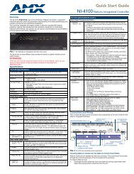
Audio output connections<br />
The switcher have two 3.5mm 5-pole captive screw audio output ports.<br />
The Fixed port delivers a fixed volume, stereo balanced/unbalanced audio output.<br />
The Variable port delivers a variable volume, stereo balanced/unbalanced audio<br />
output. The volume range is 0 (-84 dB) through 100 (0 dB). The default volume<br />
setting is 100 (0 dB). Volume is controllable only via the RS-232 port.<br />
O<br />
U<br />
T<br />
P<br />
U<br />
T<br />
S<br />
1<br />
2<br />
FIXED VARIABLE<br />
L R L R<br />
Audio output ports<br />
SW<strong>12</strong> <strong>VGA</strong> <strong>Ars</strong><br />
RS-232<br />
Figure 2-10 — Audio output connectors<br />
Connect the captive screw connectors as shown below.<br />
C Connect the sleeve to ground ( ). Connecting the sleeve to a<br />
negative (-) terminal will damage the audio output circuits.<br />
Do not tin the wires!<br />
Tip<br />
NO GROUND HERE.<br />
Sleeve(s)<br />
Tip<br />
NO GROUND HERE.<br />
Unbalanced<br />
Stereo Output<br />
Figure 2-11 — Captive screw connectors<br />
Tip<br />
Ring<br />
Tip<br />
Ring<br />
Balanced<br />
Stereo Output<br />
N A balanced audio output provides a +6 dB gain. An unbalanced audio output<br />
provides a 0 dB gain.<br />
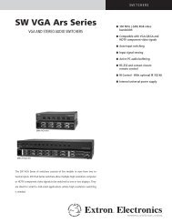
Remote control connection<br />
An RS-232 serial control port at the right edge of the rear panel is used for computer<br />
or infrared (IR) remote control of the device. The switcher’s firmware can be<br />
upgraded through the RS-232 port. See chapter 3, “Operation and Control”.<br />
The RS-232 port communications protocols are: 9600 baud, 8 data bits, 1 stop bit,<br />
no parity, and no flow control.<br />
IR remote control requires use of the IR 102 Remote Control Kit (part #70-224-01)<br />
For computer or infrared remote control, only pins 2 (transmit data), 3 (receive<br />
data), and 5 (ground) are required. Disconnect all other conductors in the<br />
attachment cable for proper operation.<br />
O<br />
U<br />
T<br />
P<br />
U<br />
T<br />
S<br />
1<br />
2<br />
FIXED VARIABLE<br />
L R L R<br />
SW<strong>12</strong> <strong>VGA</strong> <strong>Ars</strong><br />
RS-232<br />
RS-232 control port<br />
Figure 2-<strong>12</strong> — RS-232 control port<br />
5 1<br />
9 6<br />
DB9 Pin Locations<br />
Female<br />
<strong>SW8</strong>/<strong>12</strong> <strong>VGA</strong> <strong>Ars</strong> • Installation and Operation<br />
2-9