Theory of Engine Operation - Delmar Learning
Theory of Engine Operation - Delmar Learning
Theory of Engine Operation - Delmar Learning

Create successful ePaper yourself
Turn your PDF publications into a flip-book with our unique Google optimized e-Paper software.
<strong>Theory</strong> <strong>of</strong> <strong>Engine</strong> <strong>Operation</strong><br />
Upon completion and review <strong>of</strong> this chapter, you should be able to:<br />
❏ Describe basic engine operation.<br />
❏ Describe the basic laws <strong>of</strong> physics involved<br />
with engine operation.<br />
❏ Classify engines according to the number <strong>of</strong><br />
cycles, the number <strong>of</strong> cylinders, cylinder<br />
arrangement, and valvetrain type.<br />
❏ Define the four-stroke cycle theory.<br />
❏ Describe the different cylinder<br />
arrangements and the advantages <strong>of</strong> each.<br />
❏ Describe the different valvetrains used in<br />
modern engines.<br />
❏ Define engine measurement terms such as<br />
bore and stroke, displacement, compression<br />
Introduction<br />
Today’s engines are designed to meet the demands <strong>of</strong> the automobile-buying public and many<br />
government-mandated emissions and fuel economy regulations. High performance, fuel economy,<br />
reduced emissions, and reliability are demanded. To fulfill these needs, manufacturers are producing<br />
engines using lightweight blocks and cylinder heads and nontraditional materials such as<br />
powdered metals and composites.<br />
While many <strong>of</strong> the engine’s mechanical components are similar to those <strong>of</strong> over one hundred<br />
years ago, refinements in design, materials, and machining help the manufacturers improve engine<br />
performance and reliability. Many engine and support system functions are now closely controlled<br />
by the PCM. Fuel delivery, spark timing, and <strong>of</strong>ten valve timing are managed so precisely that the<br />
PCM can make adjustments within milliseconds; a millisecond is one thousandth <strong>of</strong> a second.<br />
Today’s technician is called upon to diagnose and service these advanced engines properly.<br />
The internal combustion engine used in automotive applications utilizes several laws <strong>of</strong><br />
physics and chemistry to operate. Although engine sizes, designs, and construction vary greatly,<br />
they all operate on the same basic principles. This chapter discusses these basic principles and<br />
engine designs.<br />
Major <strong>Engine</strong> Components<br />
ratio, engine efficiency, horsepower and<br />
torque, horsepower losses, mechanical<br />
efficiency, and thermal efficiency.<br />
❏ Describe the relationship between<br />
compression ratio and engine power<br />
output.<br />
❏ Define mechanical, volumetric, and thermal<br />
efficiencies, and describe factors that affect<br />
each.<br />
❏ Describe the basic operation <strong>of</strong> alternative<br />
engine designs, including diesel, Millercycle,<br />
and Stratified Charge.<br />
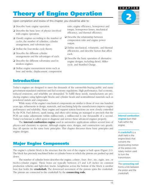
The engine’s cylinder block is the structure that the rest <strong>of</strong> the engine is built upon (Figure 2-1).<br />
The block has precisely machined holes or cylinder bores in which the pistons are pushed up and<br />
down.<br />
The number <strong>of</strong> cylinder bores describes the engine; a three-, four-, five-, six-, eight-, ten-, or<br />
twelve-cylinder engine. These bores are typically between 2.5 and 4.25 inches on common<br />
production vehicles and light-duty trucks. Lengthwise across the bottom <strong>of</strong> the block is another<br />
bore that holds the crankshaft. The downward movement <strong>of</strong> the pistons spins the crankshaft.<br />
The pistons are connected to the crankshaft by the connecting rods.<br />
15<br />
C H A P T E R<br />
2<br />
Internal combustion<br />
engines burn their<br />
fuels within the<br />
engine.<br />
A crankshaft is a<br />
shaft held in the<br />
engine block that<br />
converts the<br />
reciprocating motion<br />
<strong>of</strong> the pistons into<br />
rotary motion used<br />
to turn the<br />
transmission.<br />
The connecting rod<br />
forms a link between<br />
the piston and the<br />
crankshaft.
<strong>Engine</strong> bearings are<br />
two bearing halves<br />
that form a circle to<br />
fit around the<br />
crankshaft journals.<br />
Piston rings are<br />
hard cut rings that fit<br />
around the piston to<br />
form a seal between<br />
the piston and the<br />
cylinder wall.<br />
A wrist pin is a<br />
hardened steel pin<br />
that connects the<br />
piston to the<br />
connecting rod and<br />
allows the rod to<br />
rock back and forth<br />
as it travels with the<br />
crankshaft.<br />
The crankshaft connects to the transmission and provides the rotary motion to turn the<br />
wheels. On top <strong>of</strong> the block covering the cylinders is the cylinder head. It houses valves that open<br />
and close to allow fresh air into the cylinders and burned exhaust gases out. Look at Figure 2-2<br />
to identify these components in the engine.<br />
The cylinder block also has oil and coolant passages drilled throughout it to circulate these<br />
vital fluids to key areas in the block and up to the cylinder head. Usually, the water and oil pumps<br />
are mounted directly to the block in several different ways.<br />
The crankshaft is a long iron or steel fabrication with round bearing surfaces machined onto<br />
it called journals (Figure 2-3). The main journals form the centerline <strong>of</strong> the crankshaft. Main<br />
engine bearings fit into the main bores <strong>of</strong> the engine block, and the crankshaft can spin freely<br />
in this mounting. There is just enough clearance between the bearings and the journals to allow<br />
a thin film <strong>of</strong> pressurized oil to keep the journals from actually riding on the bearings. Half <strong>of</strong> the<br />
main bore is integral to the block. Main caps form the other half <strong>of</strong> the bore; these can be removed<br />
to service the crankshaft or bearings.<br />
The crankshaft also has journals that are <strong>of</strong>fset from the centerline. These are called rod journals<br />
because the connecting rods, fitted with rod bearings, bolt around these journals to attach to<br />
the crankshaft. The rod bearings are very similar to the main bearings. When the piston pushes<br />
the connecting rod down on the <strong>of</strong>fset journal <strong>of</strong> the crankshaft, it forces the crankshaft to rotate.<br />
The crankshaft also has counterweights or crankshaft throws that are <strong>of</strong>fset around the shaft. The<br />
weight <strong>of</strong> these throws helps <strong>of</strong>fset the crankshaft speed fluctuations and vibrations as the different<br />
cylinders produce power.<br />
The pistons are slightly smaller than the cylinders, to allow them to move up and down with<br />
minimal friction. They are fitted with piston rings that seal the area between the piston and the<br />
cylinder wall. The piston connects to the little end <strong>of</strong> the connecting rod through a wrist pin<br />
(sometimes called a piston pin) and a bushing. The force <strong>of</strong> combustion works on the top <strong>of</strong> the<br />
piston and is transferred to the crankshaft through the connecting rod. As the piston moves up and<br />
16<br />
Figure 2-1 This engine block is an eight cylinder. It is a vee style engine with four cylinders on<br />
each bank <strong>of</strong> the vee.
Figure 2-2 This engine cutaway shows the major components <strong>of</strong> the engine.<br />
Figure 2-3 A crankshaft for an eight cylinder engine.<br />
down in the cylinder, it rotates the crankshaft. This process converts the reciprocating piston<br />
motion into rotary motion, which is used to turn the wheels (Figure 2-4). A flywheel at the rear <strong>of</strong><br />
the crankshaft provides a large, stable mass for smoothing out the rotation.<br />
The cylinder head forms a tight cover for the tops <strong>of</strong> the cylinders and contains machined<br />
chambers into which the air-fuel mixture is forced (Figure 2-5). The area <strong>of</strong> the cylinder head<br />
located above the cylinder bore is called the combustion chamber. It is sealed on the top by the<br />
cylinder head and valves and on the bottom by the pistons and rings. The cylinder head also has<br />
threaded holes for the spark plugs that screw right into the head so that their tips protrude into<br />
the combustion chambers. The valves in each cylinder are opened and closed by the action <strong>of</strong> the<br />
camshaft and related valvetrain. The camshaft is connected to the crankshaft by a gear, chain, or<br />
17
18<br />
Combustion<br />
Crankshaft<br />
Down<br />
motion<br />
Figure 2-4 The engine components at work.<br />
Cylinder<br />
head<br />
Valve Valve<br />
Piston<br />
pin<br />
Up<br />
and<br />
Piston<br />
rings<br />
Piston<br />
Cylinder<br />
Connecting<br />
rod<br />
Thrust<br />
(Rotary motion)<br />
Figure 2-5 The cylinder head and valves seal the top <strong>of</strong> the combustion chamber.
Figure 2-6 A camshaft.<br />
belt, and is driven at one-half crankshaft speed. In other words, for every complete revolution the<br />
crankshaft makes, the camshaft makes one-half revolution. The camshaft may be mounted in the<br />
engine block itself, or in the cylinder head, depending on design. Some engines use two camshafts<br />
in the head; these are called dual overhead cam (DOHC) engines.<br />
The camshaft has lobes that are used to open the valves (Figure 2-6). A camshaft mounted<br />
in the block operates the valves remotely through pushrods and rocker arms; others act on followers<br />
placed directly on top <strong>of</strong> the valves. In some overhead camshaft (OHC) engines, the<br />
camshaft lobes contact the rocker arms.<br />
Lubricating oil for the engine is normally stored in the oil pan mounted to the bottom <strong>of</strong> the<br />
engine. The oil is force-fed to almost all parts <strong>of</strong> the engine by the oil pump.<br />
<strong>Engine</strong> Operating Principles<br />
One <strong>of</strong> the many laws <strong>of</strong> physics utilized within the automotive engine is thermodynamics. The<br />
driving force <strong>of</strong> the engine is the expansion <strong>of</strong> gases. Gasoline (a liquid fuel) will change state to<br />
a gas if it is heated or burned. Gasoline must be mixed with oxygen before it can burn. In addition,<br />
the air-fuel mixture must be burned in a confined area in order to produce power. Gasoline<br />
that is burned in an open container produces very little power, but if the same amount <strong>of</strong> fuel is<br />
burned in a closed container, it will expand producing usable force. When the air and fuel mixture<br />
changes states, it also expands as the molecules <strong>of</strong> the gas collide with each other and bounce<br />
apart. Increasing the temperature <strong>of</strong> the gasoline molecules increases their speed <strong>of</strong> travel, causing<br />
more collisions and expansion.<br />
Heat is generated by compressing the air-fuel mixture within the combustion chamber.<br />
Igniting the compressed mixture causes the heat, pressure, and expansion to multiply. This<br />
process releases the energy <strong>of</strong> the gasoline so it can produce work. The igniting <strong>of</strong> the mixture<br />
is a controlled burn, not an explosion. The controlled combustion releases the fuel energy at<br />
a controlled rate in the form <strong>of</strong> heat energy. The heat, and consequential expansion <strong>of</strong><br />
molecules, dramatically increases the pressure inside the combustion chamber. Typically, the<br />
pressure works on top <strong>of</strong> a piston that is connected to a crankshaft. The expanding gases push<br />
the piston down with tremendous force. As the piston is forced down, it causes the crankshaft<br />
to turn.<br />
This twisting force on the crankshaft is called torque. Torque is applied to the drive wheels<br />
through the transmission. As the engine drives the wheels to move the vehicle, a certain amount<br />
<strong>of</strong> work is done. The rate <strong>of</strong> work being performed is measured in horsepower.<br />
19<br />
Shop Manual<br />
Chapter x, page xx<br />
Thermodynamics is<br />
the study <strong>of</strong> the<br />
relationship between<br />
heat energy and<br />
mechanical energy.<br />
Torque is a rotating<br />
force around a pivot<br />
point.<br />
Horsepower is a<br />
measure <strong>of</strong> the rate<br />
<strong>of</strong> work.
Potential energy is<br />
energy that is not<br />
being used at a given<br />
time, but which can<br />
be used.<br />
Energy and Work<br />
In engineering terms, in order to have work, there must be motion. Using this definition, work can<br />
be measured by combining distance and weight and expressed as foot-pound (ft.-lb.) or Newtonmeter<br />
(Nm). These terms describe how much weight can be moved a certain distance. A footpound<br />
is the amount <strong>of</strong> energy required to lift one pound <strong>of</strong> weight one foot in distance. The<br />
amount <strong>of</strong> work required to move a 500-pound weight five feet is 2,500 foot-pounds (3,390 Nm).<br />
In the metric system, the unit used to measure force is called Newton-meters (Nm). One footpound<br />
is equal to 1.355 Nm. Torque is measured as the amount <strong>of</strong> force in newtons multiplied by<br />
the distance that the force acts in meters.<br />
Energy produces work that can be measured in units, such as torque. Basically, energy is<br />
anything that is capable <strong>of</strong> resulting in motion. Common forms <strong>of</strong> energy include electrical, chemical,<br />
heat, radiant, mechanical, and thermal.<br />
Energy cannot be created or destroyed; however, it can be stored, controlled, and changed<br />
to other forms <strong>of</strong> energy. For example, the vehicle’s battery stores chemical energy that is changed<br />
to electrical energy when a load is applied. An automotive engine transforms thermal (heat)<br />
energy into mechanical work. During combustion, when the gasoline burns, thermal energy is<br />
released. The engine converts this thermal energy into mechanical energy. Mechanical energy provides<br />
movement. The heat, expansion, and pressure during combustion all supply thermal energy<br />
within the combustion chamber. This thermal energy is converted to mechanical energy as the piston<br />
is pushed downward in the cylinder with great force.<br />
Types <strong>of</strong> Energy<br />
There are two types <strong>of</strong> energy: potential and kinetic. Potential energy is available to be used but<br />
is not being used. An example <strong>of</strong> this in the automobile is the chemical energy <strong>of</strong> the battery when<br />
the engine and ignition is turned <strong>of</strong>f. Most <strong>of</strong> the chemical energy is stored as potential energy.<br />
(A very small percentage <strong>of</strong> the available energy is actually being used to keep computer memories<br />
alive.) When the ignition key is turned to start and the starter begins to crank the engine over,<br />
kinetic energy is being used. Kinetic energy is energy that is being used or working. The battery<br />
is now providing significant chemical energy to the starter so it can do work.<br />
Energy Conversion<br />
In our example <strong>of</strong> the battery starting the engine, there are several energy conversions that occur.<br />
Energy cannot be destroyed or eliminated, but it can be converted from one state or form to<br />
another. The starter converts the chemical energy from the battery into electrical energy to engage<br />
the starter. The starter converts this electrical energy into mechanical energy to crank the engine<br />
over. At the same time, chemical energy from the battery is being converted to electrical energy<br />
to provide power to the fuel and ignition systems so they will have the needed fuel and spark to<br />
run. Once the engine is running, combustion occurs. Combustion uses the potential energy in<br />
gasoline and converts it into kinetic energy by burning it. The chemical energy <strong>of</strong> the fuel is<br />
converted to thermal energy by the heart produced during combustion. The thermal energy is<br />
converted to mechanical energy by the movement <strong>of</strong> the pistons and the crankshaft. The following<br />
energy conversions are all common automotive applications:<br />
Chemical Energy Conversion to Thermal Energy<br />
As fuel is burned in the combustion chambers, the chemical energy in the fuel is converted to<br />
thermal energy.<br />
Thermal Energy Conversion to Mechanical Energy<br />
As the heat, pressure, and expansion <strong>of</strong> gases develop during combustion, thermal energy<br />
increases. This thermal energy is converted to mechanical energy to drive the vehicle, through<br />
20
energy exerted on top <strong>of</strong> the pistons that turns the crankshaft to drive the transmission and drive<br />
wheels.<br />
Chemical Energy Conversion to Electrical Energy<br />
The battery stores chemical energy and converts it to electrical energy as electrical loads such as<br />
the starter, the powertrain control module, the fuel injectors, and the radio demand electricity.<br />
Electrical Energy Conversion to Mechanical Energy<br />
The starter, fuel injectors, electric cooling fan, and windshield wiper motor are just a few <strong>of</strong> the<br />
many automotive applications <strong>of</strong> conversion <strong>of</strong> electrical energy into mechanical motion.<br />
Mechanical Energy Conversion to Electrical Energy<br />
The generator that provides electrical energy to the battery and other electrical loads uses the<br />
mechanical energy <strong>of</strong> rotation through a belt <strong>of</strong>f the spinning crankshaft to generate electrical<br />
energy.<br />
Mechanical Energy Conversion to Thermal Energy<br />
The braking system on a traditional internal combustion engine vehicle is a fine example <strong>of</strong> this<br />
form <strong>of</strong> energy conversion. The mechanical energy <strong>of</strong> the rotating wheels is changed into thermal<br />
energy through the friction created between the rotating brake discs or drums and the stationary<br />
friction surfaces <strong>of</strong> the brake pads or shoes. The thermal energy is dissipated to the atmosphere.<br />
Newton’s Laws <strong>of</strong> Motion<br />
First Law<br />
A body in motion tends to stay in motion. A body at rest tends to stay at rest. Forces applied to<br />
the body can overcome this tendency. Certainly the crankshaft, transmission, and drive wheels will<br />
not propel the car forward from a rest position unless significant force is applied to the pistons to<br />
rotate the crankshaft.<br />
Second Law<br />
A body’s acceleration is directly proportional to the force applied to it. The greater the force<br />
applied to the drive wheels, the greater the acceleration <strong>of</strong> the vehicle.<br />
Third Law<br />
For every action, there is an equal and opposite reaction. A simple application <strong>of</strong> this law on the<br />
automobile involves the suspension system. When the tire travels over a bump, the wheel moves<br />
upward with a force that opposes spring tension. When the wheel passes the bump, the spring<br />
exerts its opposite reaction to force the wheel back down toward the road.<br />
Inertia<br />
Inertia is the tendency <strong>of</strong> an object at rest (static inertia) to stay at rest or an object in motion<br />
(dynamic inertia) to stay in motion. The heavy flywheel attached to the end <strong>of</strong> the crankshaft on<br />
manual transmission vehicles uses the inertia <strong>of</strong> the rotating crankshaft to help it continue to spin<br />
smoothly between the combustion events in the cylinders.<br />
Momentum<br />
Momentum is when force overcomes static inertia and causes movement <strong>of</strong> an object. As the<br />
object moves, it gains momentum. Momentum is calculated by multiplying the object’s weight<br />
times its speed. An opposing force will reduce momentum.<br />
Friction<br />
In the engine, the piston rings generate friction against the cylinder walls. Friction opposes<br />
momentum and mechanical energy. Friction creates heat and reduces the mechanical energy <strong>of</strong><br />
21<br />
Friction is resistance<br />
to motion when one<br />
object moves across<br />
another object.<br />
Friction generates<br />
heat.
the piston as it is pushed downward to turn the crankshaft. This is an example <strong>of</strong> how engine efficiency<br />
is decreased. Friction may occur in solids, liquids, and gases. The airflow over a vehicle<br />
causes friction. The manufacturers carefully engineer their vehicles to be aerodynamic. This means<br />
that the resistance to motion from friction between the vehicle and the air is minimized. This is<br />
carefully calculated and measured as the coefficient <strong>of</strong> draft (Cd). Unfortunately, there are conditions<br />
and vehicles that can lose up to half <strong>of</strong> their mechanical energy to aerodynamic drag.<br />
Behavior <strong>of</strong> Liquids and Gases<br />
Molecular Energy<br />
Electrons are in constant motion around the nucleus <strong>of</strong> atoms or molecules. Kinetic energy is always<br />
occurring. The kinetic energy <strong>of</strong> liquids, gases, and solids changes in response to temperature.<br />
When temperature decreases, so does kinetic energy. As temperature increases, so does kinetic<br />
energy. Solids have the slowest reaction to temperature, while gases have the quickest response to<br />
changes in temperature. We know this theory already through our discussion <strong>of</strong> combustion. As<br />
temperature increases within the combustion chamber, the gases rapidly expand and the increasing<br />
kinetic energy is used to create thermal energy that is converted into mechanical energy.<br />
Temperature<br />
The volume <strong>of</strong> liquids, gases, and solids increases with temperature. It is the increased volume <strong>of</strong><br />
gases on top <strong>of</strong> the pistons that produces the force to push the piston downward. When filling<br />
engine fluids, such as tire air pressure and coolant, we must be aware <strong>of</strong> the effects <strong>of</strong> temperature<br />
on volume. It is easy to overfill a coolant reservoir if the coolant is at ambient temperature<br />
and you top the fluid <strong>of</strong>f to the maximum level. As the fluid heats up, it may expand beyond the<br />
capacity <strong>of</strong> the reservoir and develop enough pressure to blow the cap’s pressure relief valve.<br />
Pressure and Compressibility<br />
Pressure is always applied equally to all surfaces <strong>of</strong> a container. If there is a leak in the container,<br />
the pressure will leak out and equalize with the atmospheric pressure. Gases and liquids both<br />
flow, so they are classified as fluids. But there are distinct and significant differences between the<br />
characteristics <strong>of</strong> gases and liquids. Gases can be compressed; the molecules squeeze tighter<br />
together and form greater pressure. You can easily fill a tire with excess pressure. Luckily, you can<br />
further compress the gases in a combustion chamber to produce more power. Liquids, on the<br />
other hand, cannot be compressed. A liquid fills a chamber, and you cannot add more liquid; you<br />
can only increase pressure. Brake and clutch hydraulic systems work with liquids. When you<br />
depress the clutch or brake pedals, you move the liquid, under pressure to exert force on a piston.<br />
This force produces mechanical work from the brake caliper piston or the clutch hydraulic<br />
lever. If there is a leak in the system, air can enter. Air is a gas and is compressible. Air in a<br />
hydraulic system will cause a lack <strong>of</strong> pressure and force.<br />
Pressure and Vacuum<br />
Air is a gas with weight and mass. It is layered high above the surface <strong>of</strong> the earth and exerts a<br />
pressure on the earth’s surface. This pressure is called atmospheric pressure. A column <strong>of</strong> air<br />
extending from the earth’s surface at seal level to the outer edge <strong>of</strong> the earth’s atmosphere weighs<br />
14.7 pounds. We say that atmospheric pressure is 14.7 pounds at sea level. This pressure changes<br />
as we climb in altitude. If we are 14,000 feet above sea level in the mountains, that column <strong>of</strong> air<br />
no longer weighs 14.7 lbs; atmospheric pressure decreases. Also, as temperature increases, the<br />
22
molecules become less dense and therefore weigh less; atmospheric pressure decreases. These<br />
changes in atmospheric pressure caused by altitude and temperature are important for the PCM<br />
to know about in order to deliver the correct amount <strong>of</strong> fuel for the actual amount <strong>of</strong> air in the<br />
cylinder.<br />
When air pressure is greater than atmospheric pressure, it is a positive pressure. When air<br />
pressure is lower than atmospheric, it is a negative pressure or vacuum. The engine creates vacuum<br />
as the engine valves are closed and the piston moves from the top <strong>of</strong> the cylinder to the bottom<br />
<strong>of</strong> the cylinder. The volume <strong>of</strong> the chamber has increased, but no more air has been added<br />
to fill the space; pressure is reduced and a vacuum is formed. Vacuum is typically measured in<br />
inches <strong>of</strong> mercury vacuum ("hg vacuum). At atmospheric pressure, there are 0 "hg vacuum. When<br />
there is a total absence <strong>of</strong> air or O absolute pressure (no atmospheric pressure at all), a perfect<br />
vacuum can be measured at 29.9 "hg vacuum.<br />
An engine develops significant vacuum during its intake strokes as the pistons move downward<br />
and the valves begin to close. Liquids, solids, and gases move from an area <strong>of</strong> high pressure<br />
to an area <strong>of</strong> low pressure. Automotive engines rely on engine vacuum and this principle to fill<br />
the combustion chambers with air to support combustion. When the throttle is opened, atmospheric<br />
pressure flows rapidly into the low pressure area <strong>of</strong> the cylinder to fill it with air. An engine<br />
that cannot develop adequate vacuum will not pull in enough air to make maximum power. A<br />
modern, fine-running engine will typically develop about 16–18 "hg vacuum at idle.<br />
Turbocharged and supercharged engines increase this pressure difference before and after the<br />
throttle plate to help fill the combustion chambers fully under all conditions. The engine still develops<br />
the same amount <strong>of</strong> vacuum, but the supercharger or turbocharger delivers roughly 8–15 psi<br />
<strong>of</strong> pressure over atmospheric behind the throttle. When the throttle opens, the greater pressure<br />
difference increases airflow into the cylinders.<br />
<strong>Engine</strong> <strong>Operation</strong><br />
Most automotive and truck engines are four-stroke cycle engines. A stroke is the movement <strong>of</strong><br />
the piston from one end <strong>of</strong> its travel to the other; for example, if the piston is at the top <strong>of</strong> its travel<br />
and then is moved to the bottom <strong>of</strong> its travel, one stroke has occurred. Another stroke occurs<br />
when the piston is moved from the bottom <strong>of</strong> its travel to the top again. A cycle is a sequence<br />
that is repeated. In the four-stroke engine, four strokes are required to complete one powerproducing<br />
cycle.<br />
The internal combustion engine must draw in an air-fuel mixture, compress the mixture,<br />
ignite the mixture, then expel the exhaust. This is accomplished in four piston strokes (Figure 2-7).<br />
The first stroke <strong>of</strong> the cycle is the intake stroke (see Figure 2-7A). As the piston moves down<br />
from top dead center (TDC), the intake valve is opened so the vaporized air-fuel mixture can be<br />
pushed into the cylinder by atmospheric pressure. As the piston moves downward in its stroke, a<br />
vacuum is created (low pressure). Since high pressure moves toward low pressure, the air-fuel<br />
mixture is pushed past the open intake valve and into the cylinder. After the piston reaches<br />
bottom dead center (BDC), the intake valve is closed, and the stroke is completed. Closing the<br />
intake valve after BDC allows an additional amount <strong>of</strong> air-fuel mixture to enter the cylinder. Even<br />
though the piston is at the end <strong>of</strong> its stroke and no more vacuum is created, the additional mixture<br />
enters the cylinder because it weighs more than air alone. The momentum <strong>of</strong> air flowing into<br />
the cylinder also helps pull more air in after the piston has reached BDC.<br />
The compression stroke begins as the piston starts its travel back to TDC (see Figure 2-7B).<br />
The intake and exhaust valves are both closed, trapping the air-fuel mixture in the combustion<br />
chamber. The movement <strong>of</strong> the piston toward TDC compresses the mixture. As the molecules <strong>of</strong><br />
the mixture are pressed tightly together, they begin to heat. When the piston reaches TDC, the<br />
mixture is fully compressed and highly combustible. Compressing the mixture provides for better<br />
burning and for intense combustion. The ignition system induces a spark at exactly the right time<br />
23<br />
Shop Manual<br />
Chapter x, page xx<br />
The stroke is the<br />
amount <strong>of</strong> piston<br />
travel from TDC to<br />
BDC measured in<br />
inches or millimeters.<br />
A cycle is a complete<br />
sequence <strong>of</strong> events.<br />
Top dead center<br />
(TDC) is a term used<br />
to indicate that the<br />
piston is at the very<br />
top <strong>of</strong> its stroke.<br />
Bottom dead<br />
center (BDC) is a<br />
term used to indicate<br />
that the piston is at<br />
the very bottom <strong>of</strong><br />
its stroke.
Valve overlap is the<br />
length <strong>of</strong> time,<br />
measured in degrees<br />
<strong>of</strong> crankshaft<br />
revolution, that the<br />
intake and exhaust<br />
valves <strong>of</strong> the same<br />
combustion chamber<br />
are open<br />
simultaneously.<br />
Reciprocating is an<br />
up-and-down or<br />
back-and-forth<br />
motion.<br />
to produce maximum power on top <strong>of</strong> the piston when it is at about ten degrees <strong>of</strong> crankshaft<br />
rotation past TDC. This ensures that peak pressure will act on the piston when it is just headed<br />
downward and before the volume <strong>of</strong> the chamber has increased significantly.<br />
When the spark occurs in the compressed mixture, the rapid burning causes the molecules<br />
to expand, beginning the power stroke (see Figure 2-7C). The expanding molecules create a pressure<br />
above the piston and push it downward. The downward movement <strong>of</strong> the piston in this<br />
stroke is the only time the engine is productive concerning power output. During the power<br />
stroke, the intake and exhaust valves remain closed.<br />
The exhaust stroke <strong>of</strong> the cycle begins when the piston reaches BDC <strong>of</strong> the power stroke<br />
(see Figure 2-7D). Just prior to the piston reaching BDC, the exhaust valve is opened. The<br />
upward movement <strong>of</strong> the piston back toward TDC pushes out the exhaust gases from the cylinder<br />
past the exhaust valve and into the vehicle’s exhaust system. As the piston approaches TDC,<br />
the intake valve opens and the exhaust valve is closed a few degrees after TDC. The degrees <strong>of</strong><br />
crankshaft rotation when both the intake and exhaust valves are open is called valve overlap.<br />
Valve overlap uses the movement <strong>of</strong> air to help fully clean out the spent gases and fill the<br />
chamber with a fresh charge <strong>of</strong> air and fuel. The cycle is then repeated again as the piston<br />
begins the intake stroke. This cycle is occurring simultaneously in the other cylinders <strong>of</strong> the<br />
engine, though the individual strokes do not occur at the same time. For example, cylinder<br />
number one will produce its power stroke, then, while its exhaust stroke occurs, cylinder number<br />
three will be on its power stroke. This keeps rotating the crankshaft around with regular<br />
impulses. Most engines in use today are referred to as reciprocating. Power is produced by the<br />
up and down movement <strong>of</strong> the piston in the cylinder. This linear motion is then converted to<br />
rotary motion by a crankshaft.<br />
A B I T O F H I S T O R Y<br />
License plates made their first appearance on vehicles in the U.S. in 1901. In 1905, California began<br />
licensing and registering motor vehicles. By the end <strong>of</strong> 1905, California had registered 17,015 vehicles.<br />
Owners had to conspicuously display the circular or octagonal tags in the vehicle. In order<br />
to register the vehicle, it had to have working lamps, satisfactory brakes, and a bell or a horn.<br />
24<br />
Intake valve<br />
closing<br />
Air/fuel<br />
mixture<br />
Both valves<br />
closed<br />
Compression stroke Compression stroke<br />
51˚BTDC 20˚BTDC<br />
Ignition<br />
Both valves<br />
closed<br />
A B C D<br />
Power stroke<br />
Exhaust valve<br />
opening<br />
Power stroke<br />
57˚BBDC<br />
Figure 2-7 The four strokes <strong>of</strong> an automotive engine: (A) intake stroke, (B) compression stroke,<br />
(C) power stroke, (D) exhaust stroke.
<strong>Engine</strong> Classifications<br />
<strong>Engine</strong> classification is usually based on the number <strong>of</strong> cycles, the number <strong>of</strong> cylinders, cylinder<br />
arrangement, and valvetrain type. Additional descriptors include the location and number <strong>of</strong><br />
camshafts and the type <strong>of</strong> fuel and ignition systems. <strong>Engine</strong> displacement is commonly used to<br />
identify engine size.<br />
Sometimes, different methods may be used to identify the same engine. For example, a<br />
Chrysler 2.0 liter DOHC is also identified as a 420A and D4FE. In this case, the engine has a displacement<br />
<strong>of</strong> 2.0 liters and uses dual overhead camshafts. The 420A is derived from four valves<br />
per cylinder, 2.0 liter displacement, and American built. The D4FE means the engine uses dual<br />
overhead camshafts with four valves per cylinder and has front exhaust (the exhaust manifold is<br />
mounted facing the front <strong>of</strong> the vehicle). This section will define many <strong>of</strong> the terms used by automotive<br />
manufacturers to classify their engines.<br />
Number <strong>of</strong> Cylinders<br />
One cylinder would not be able to produce sufficient power to meet the demands <strong>of</strong> today’s vehicles.<br />
Most automotive and truck engines use three, four, five, six, eight, ten, or twelve cylinders.<br />
The number <strong>of</strong> cylinders used by the manufacturer is determined by the amount <strong>of</strong> work required<br />
from the engine. Generally, the greater the number <strong>of</strong> cylinders, the more power the engine can<br />
produce. Also, the more cylinders, the greater number <strong>of</strong> power pulses in one complete 720degree<br />
cycle. This produces a smoother running engine.<br />
Vehicle manufacturers attempt to achieve a balance among power, economy, weight, and<br />
operating characteristics. An engine having more cylinders generally runs smoother than those<br />
having three or four cylinders, because there is less crankshaft rotation between power strokes;<br />
however, adding more cylinders increases the weight <strong>of</strong> the vehicle and the cost <strong>of</strong> production.<br />
Cylinder Arrangement<br />
<strong>Engine</strong>s are also classified by the arrangement <strong>of</strong> the cylinders. The cylinder arrangement used is<br />
determined by vehicle design and purpose. The most common engine designs are in-line and V-type.<br />
The in-line engine places all <strong>of</strong> its cylinders in a single row (Figure 2-8). Advantages <strong>of</strong> this<br />
engine design include ease <strong>of</strong> manufacturing and serviceability. The disadvantage <strong>of</strong> this engine<br />
design is the block height. Since the engine is tall, aerodynamic design <strong>of</strong> the vehicle is harder to<br />
achieve. Many manufacturers overcome this disadvantage by installing a transverse-mounted<br />
engine in the engine compartment <strong>of</strong> front-wheel-drive vehicles. A modification <strong>of</strong> the in-line<br />
design is the slant cylinder (Figure 2-9). By tilting the engine slightly, the manufacturer can lower<br />
the height <strong>of</strong> the hood line for improvement in the vehicle’s aerodynamics.<br />
The V-type engine has two rows <strong>of</strong> cylinders set 60 to 90 degrees from each other (Figure 2-10).<br />
The V-type design allows for a shorter block height, thus easier vehicle aerodynamics. The length <strong>of</strong><br />
the block is also shorter than in-line engines with the same number <strong>of</strong> cylinders.<br />
A common engine design used for rear engine vehicles, as well as the front-wheel-drive<br />
Subaru, is the opposed cylinder engine (Figure 2-11). This engine design has two rows <strong>of</strong> cylinders<br />
directly across from each other. The main advantage <strong>of</strong> this engine design is the very small<br />
vertical height.<br />
Valve Train Type<br />
<strong>Engine</strong>s can also be classified by their valvetrain types. The three most commonly used valvetrains<br />
are the:<br />
1. Overhead valve (OHV). The intake and exhaust valves are located in the cylinder head,<br />
while the camshaft and lifters are located in the engine block (Figure 2-12). Valvetrain components<br />
<strong>of</strong> this design include lifters, pushrods, and rocker arms.<br />
25<br />
A transversemounted<br />
engine<br />
faces from side to<br />
side instead <strong>of</strong> front<br />
to back.<br />
The opposed cylinder<br />
engine may be called<br />
a pancake engine.<br />
An overhead valve<br />
(OHV) engine has<br />
the valves mounted<br />
in the cylinder head<br />
and the camshaft<br />
mounted in the<br />
block.
26<br />
4 cylinder<br />
Figure 2-8 In-line engines are designed<br />
for ease <strong>of</strong> construction and service.<br />
8 cylinder<br />
6 cylinder<br />
Figure 2-10 The V-type engine design allows<br />
for lower and shorter hood lines.<br />
Camshaft<br />
Lifter<br />
6 cylinder<br />
Pushrod<br />
Rocker arm<br />
Figure 2-9 Slant cylinder design lowers<br />
the overall height <strong>of</strong> the engine.<br />
Figure 2-11 Opposed<br />
cylinder engine design.<br />
Valve<br />
Figure 2-12 The overhead valve engine has been one <strong>of</strong> the most popular valve designs.
Exhaust<br />
camshaft<br />
2. Overhead cam (OHC). The intake and exhaust valves are located in the cylinder head<br />
along with the camshaft. The valves are operated directly by the camshaft and a follower,<br />
eliminating many <strong>of</strong> the moving parts required in the OHV engine. If a single camshaft is used<br />
in each cylinder head, the engine is classified as a single overhead cam (SOHC) engine. This<br />
designation is used even if the engine has two cylinder heads with one camshaft each.<br />
3. Dual overhead cam (DOHC). The DOHC uses separate camshafts for the intake and<br />
exhaust valves. A DOHC V8 engine is equipped with a total <strong>of</strong> four camshafts (Figure 2-13).<br />
Ignition Types<br />
Hydraulic<br />
lash adjuster<br />
Rocker<br />
arm<br />
Intake<br />
camshaft<br />
Exhaust port Intake port<br />
Exhaust<br />
valve<br />
Intake<br />
valve<br />
Figure 2-13 The dual overhead camshaft engine places two camshafts in the cylinder head.<br />
Most automotive engines use a mixture <strong>of</strong> gasoline and air, which is compressed and then ignited<br />
with a spark plug. This type <strong>of</strong> engine is referred to as a spark-ignition (SI) engine. Diesel<br />
engines, on the other hand, do not use spark plugs. The fuel and air mixture is ignited by the heat<br />
created during the compression stroke. These engines are referred to as compression-ignition<br />
(CI) engines.<br />
Spark ignition engines may be further identified by the type <strong>of</strong> ignition system used. The<br />
older, less common design is called a distributor ignition (DI). This form <strong>of</strong> ignition uses a<br />
mechanical device to distribute the spark from one coil to the correct cylinder. Newer ignition systems<br />
tend to use multiple coils to deliver spark to the cylinders. These systems are termed electronic<br />
ignition (EI) systems. A form <strong>of</strong> EI ignition is the coil on plug (COP) ignition system, where<br />
27<br />
A dual overhead<br />
cam (DOHC) engine<br />
has two camshafts<br />
mounted above each<br />
cylinder head.<br />
A spark-ignition<br />
(SI) engine ignites<br />
the air-fuel ratio in<br />
the combustion<br />
chamber by a spark<br />
across the spark plug<br />
electrodes.<br />
A compressionignition<br />
(CI) engine<br />
ignites the air-fuel<br />
mixture in the<br />
cylinders from the<br />
heat <strong>of</strong> compression.<br />
A coil is an electrical<br />
device that converts<br />
low voltage from the<br />
battery into a very<br />
high voltage that is<br />
able to push a spark<br />
across the gap <strong>of</strong> the<br />
spark plug.
Fuel injection<br />
systems use the<br />
PCM to control<br />
electromechanical<br />
devices, fuel injectors<br />
that deliver a closely<br />
controlled amount <strong>of</strong><br />
fuel to the cylinders.<br />
28<br />
Figure 2-14 This late model V-6 engine has a coil on top <strong>of</strong> each spark plug (this is the forward<br />
cylinder head).<br />
one coil sits on top <strong>of</strong> each spark plug to deliver spark directly (Figure 2-14). Another type <strong>of</strong> EI<br />
ignition is called a waste spark ignition system, where one coil provides spark to two cylinders.<br />
Fuel Injection Types<br />
All new vehicles currently sold in the United States and Canada use a form <strong>of</strong> fuel injection to<br />
deliver fuel to the engine. Fuel injectors squirt just the right amount <strong>of</strong> fuel for each combustion<br />
event. The fuel injectors are controlled by the PCM. Most fuel injection systems deliver fuel into the<br />
intake system very close to the back <strong>of</strong> the intake valve. These systems use one injector per cylinder<br />
and are termed multi-point fuel injection (MPFI). Many manufacturers refine this system to make<br />
sure that the injectors each fire on each cylinder’s intake stroke for excellent mixing <strong>of</strong> the air and<br />
fuel. These systems are called sequential fuel injection (SFI) systems because the injectors fire in the<br />
same sequence as the cylinders. A few newer gas engines use fuel injectors that spray fuel directly<br />
into the combustion chamber. These are called gasoline direct injection (GDI) systems. This type<br />
<strong>of</strong> fuel injection improves combustion and reduces fuel consumption and emissions.<br />
Variable Valve Timing<br />
Many newer engines are using variable valve timing (VVT) systems that change the relationship<br />
<strong>of</strong> the camshaft to the crankshaft at different engine speeds. This allows the camshaft to open<br />
the valves at more beneficial times, depending on engine speed. The manufacturer will <strong>of</strong>ten use<br />
the acronym VVT to further describe the engine design.<br />
<strong>Engine</strong> Vibration<br />
Balance Shafts<br />
Many engine designs have inherent vibrations. The in-line four-cylinder engine is an example <strong>of</strong><br />
this problem. Some engine manufacturers use balance shafts to counteract engine vibration. Fourcylinder<br />
engine vibration occurs at two positions <strong>of</strong> piston travel. The first is when a piston<br />
reaches TDC. The inertia <strong>of</strong> the piston moving upward creates an upward force in the engine. The
second vibration occurs when all pistons are level. At this point, the downward moving pistons<br />
have accelerated and have traveled more than half their travel distance. The engine forces are<br />
downward because the pistons have been accelerating since they have to travel a greater distance<br />
than the upward moving pistons to reach the point at which all pistons are level.<br />
The following formula (with values plugged in) demonstrates the principle that piston travel<br />
is further at the top 90 degrees verses the bottom 90 degrees <strong>of</strong> crankshaft rotation. First, determine<br />
the total length. This is rod length, from the center <strong>of</strong> the big end to the center <strong>of</strong> the small<br />
end, and the crankshaft throw (stroke divided by 2). Next, determine the amount the piston drops<br />
in the first 90 degrees <strong>of</strong> crankshaft rotation (TDC to 90 degrees). Once this is known, the final<br />
amount <strong>of</strong> piston travel can be determined. The following formula is for a 2.5-liter, four-cylinder<br />
engine (the values are in millimeters):<br />
1. Total length 5 rod 1 throw (stroke/2)<br />
209 5 157 1 52<br />
2. Travel the first 90 degrees <strong>of</strong> crankshaft rotation:<br />
209 – 1572 1 522 5 209 – 21945 5 148<br />
3. Total – difference 5 piston travel to midpoint<br />
209 – 148 5 61 (travel for first 90 degrees <strong>of</strong> crankshaft rotation)<br />
4. Bottom half <strong>of</strong> travel 5 distance left – rod length 1 throw<br />
148 – 157 1 52 5 43 (travel for last 90 degrees <strong>of</strong> crankshaft rotation)<br />
The balance shafts rotate at twice the speed <strong>of</strong> the crankshaft. This creates a force that counteracts<br />
crankshaft vibrations. At TDC, the forces <strong>of</strong> the piston will exert upward; to <strong>of</strong>fset the vibration,<br />
the crankshaft and the balance shaft(s) lobes have a downward force (Figure 2-15). At 90 degrees<br />
<strong>of</strong> crankshaft rotation, all pistons are level. Remember, the pistons traveling downward have traveled<br />
more than half <strong>of</strong> their travel distance to reach this point. The engine forces are in a downward direction<br />
since these pistons have been accelerated to reach the midpoint at the same time as the upward<br />
moving pistons, which need to travel a lesser distance. Since the balance shaft(s) rotate at twice the<br />
crankshaft speed, the lobes <strong>of</strong> the balance shaft(s) are facing up, exerting an upward force to counteract<br />
the downward forces <strong>of</strong> the pistons (Figure 2-16). At 180 degrees <strong>of</strong> crankshaft rotation, the<br />
upward-moving pistons reach TDC, and again exert an upward force. The balance shaft(s) have their<br />
lobes facing downward to exert a downward force to counteract the upward force (Figure 2-17).<br />
Finally, at 270 degrees <strong>of</strong> crankshaft rotation, the pistons are level again. At this point, the lobes <strong>of</strong><br />
the balance shaft(s) are exerting an upward force to counteract the downward force <strong>of</strong> the pistons<br />
(Figure 2-18). Balance shafts may also be used in vee engines (Figure 2-19).<br />
Some balance shafts on overhead valve (OHV) engines are mounted in the block V above<br />
the camshaft (Figure 2-20). Bearing journals on the balance shaft are mounted on bushings in the<br />
block. Some engines use two gears mounted on the front end <strong>of</strong> the camshaft to drive the balance<br />
shaft. The inner camshaft gear is meshed with the gear on the balance shaft, and the timing chain<br />
surrounds the outer camshaft gear and the crankshaft gear to drive the camshaft. On some dual<br />
overhead cam (DOHC) engines, the balance shaft is mounted in the block above the crankshaft<br />
(Figure 2-20).<br />
AUTHOR’S NOTE: One time a student drove his freshly rebuilt engine into the<br />
shop to have me look at why it “shook” so badly. The student said the engine ran well<br />
and had plenty <strong>of</strong> power but had a very significant vibration throughout the engine rpm<br />
range. We took a test drive to verify the concern and tested the engine and transmission<br />
mounts. During further discussion, I realized the engine had balance shafts and asked the<br />
student if he had lined them up according to the marks described in the service information.<br />
Unfortunately, he was unaware <strong>of</strong> that necessary step. Once he successfully timed his balance<br />
shafts, his “new” engine ran beautifully.<br />
29
30<br />
Crankshaft<br />
Balance<br />
shafts<br />
Upward force<br />
Downward<br />
force<br />
Figure 2-15 Balance shaft operation with<br />
piston moving upward.<br />
Upward force from<br />
other pistons<br />
reaching TDC<br />
Figure 2-17 Balance shaft operation in<br />
relation to other pistons.<br />
Upward<br />
force<br />
Downward<br />
force<br />
Figure 2-16 Balance shaft operation with<br />
piston moving downward.<br />
Downward<br />
force <strong>of</strong> other<br />
pistons<br />
Figure 2-18 Balance shaft operation with<br />
other pistons moving downward.
Plug<br />
<strong>Engine</strong> Displacement<br />
Retainer<br />
Figure 2-19 A balance shaft used in an overhead valve engine.<br />
Figure 2-20 Balance shaft in a DOHC V-6 engine.<br />
Counter<br />
balance<br />
shaft<br />
Balance<br />
shaft<br />
Gear<br />
FRT<br />
Displacement is the volume <strong>of</strong> the cylinder between TDC and BDC measured in cubic inches,<br />
cubic centimeters, or liters (Figure 2-21). Most engines today are identified by their displacement<br />
in liters. <strong>Engine</strong> displacement is an indicator <strong>of</strong> engine size and power output. The more fuel that<br />
can be burned, the greater amount <strong>of</strong> energy that can be produced. To burn more fuel, more air<br />
must also enter the cylinders. <strong>Engine</strong> displacement measurements are an indicator <strong>of</strong> the amount<br />
or mass <strong>of</strong> air that can enter the engine. The mass <strong>of</strong> air allowed to enter the cylinders is controlled<br />
by a throttle plate. If the throttle plate is closed, a smaller mass <strong>of</strong> air is allowed to enter the cylinder,<br />
and the power output is reduced. As the throttle plate is opened, the mass <strong>of</strong> air allowed to<br />
enter the cylinders is increased, resulting in greater power output. The more air that is allowed,<br />
the more fuel that can be added to it. As engine speed increases, it will eventually reach a point<br />
at which no more air can enter. Any increase in speed beyond this point causes a loss in power<br />
output. The major factor in determining the maximum mass <strong>of</strong> air that can enter the cylinders is<br />
engine displacement. The amount <strong>of</strong> displacement is determined by the number <strong>of</strong> cylinders,<br />
cylinder bore, and length <strong>of</strong> the piston stroke (Figure 2-22).<br />
Bore and Stroke. The bore <strong>of</strong> the cylinder is its diameter measured in inches (in.) or<br />
millimeters (mm). The stroke is the amount <strong>of</strong> piston travel from TDC to BDC measured in inches<br />
or millimeters. An oversquare engine is used when high rpm (revolutions per minute) output is<br />
31<br />
Displacement is the<br />
measure <strong>of</strong> engine<br />
volume. The larger<br />
the displacement,<br />
the greater the<br />
power output.<br />
A bore is the<br />
diameter <strong>of</strong> a hole.<br />
If the bore is larger<br />
than its stroke, the<br />
engine is referred to<br />
as oversquare. If the<br />
bore is smaller than<br />
the stroke, the<br />
engine is referred to<br />
as undersquare. A<br />
square engine has<br />
the same bore size as<br />
it does stroke.<br />
Stroke is the<br />
distance that the<br />
piston travels from<br />
top dead center<br />
(TDC) to bottom<br />
dead center (BDC) or<br />
vice versa.
Stroke<br />
(inches)<br />
Cubic inches,<br />
cubic<br />
centimeters,<br />
or liters<br />
Some engine<br />
enthusiasts say<br />
“there is no<br />
replacement for<br />
displacement.”<br />
Bore<br />
(inches)<br />
Figure 2-21 Displacement is the volume <strong>of</strong> the<br />
cylinder between TDC and BDC.<br />
required. This meets the requirements <strong>of</strong> many automotive engines. Most truck engines are<br />
designed as undersquare since they deliver more low-end torque.<br />
Calculating <strong>Engine</strong> Displacement<br />
Mathematical formulas can be used to determine the displacement <strong>of</strong> an engine. As with many<br />
mathematical formulas, there is more than one method that can be used. The first is as follows:<br />
<strong>Engine</strong> displacement = 0.785 3 B2 3 S 3 N<br />
where 0.785 is a constant<br />
B 5 bore<br />
S 5 stroke<br />
N 5 number <strong>of</strong> cylinders<br />
The second formula is:<br />
<strong>Engine</strong> displacement 5p3R2 3 S 3 N<br />
where p53.1416 R 5 bore radius (diameter/2)<br />
S 5 stroke length<br />
N 5 number <strong>of</strong> cylinders<br />
Pi times the radius squared is equal to the area <strong>of</strong> the cylinder cross section. This area is then<br />
multiplied by the stroke, and this product is multiplied by the number <strong>of</strong> cylinders.<br />
The calculation for total cubic inch displacement (CID) <strong>of</strong> a V6 engine with a bore size <strong>of</strong><br />
3.800 inches (9.65 cm) and stroke length <strong>of</strong> 3.400 inches (8.64 cm) would be as follows:<br />
<strong>Engine</strong> displacement 5 0.785 3 3.8002 3 3.400 3 6 5 231.24 CID<br />
or<br />
<strong>Engine</strong> displacement 5 3.1416 3 1.92 3 3.400 3 6 5 231.35 CID<br />
The difference in decimal values is due to rounding pi to four digits. Round the product to the<br />
nearest whole number. In this case, the CID would be expressed as 231.<br />
32<br />
TDC<br />
BDC<br />
Bore<br />
Piston at BDC<br />
(bottom dead center)<br />
Stroke<br />
CL Crank<br />
Piston at TDC<br />
(top dead center)<br />
Bore<br />
= Bore stroke ratio<br />
Stroke<br />
Figure 2-22 The bore and stroke determine the amount<br />
<strong>of</strong> displacement <strong>of</strong> the cylinder.
Most engine manufacturers designate engine size by metric displacement. To calculate<br />
engine displacement in cubic centimeters or liters, simply use the metric measurements in the<br />
displacement formula. In the preceding example, the result would be 3,789.56 cc, which would<br />
be rounded <strong>of</strong>f to 3.8 liters. Another way to convert to metric measurements is to use the CID and<br />
multiply it by .01639 to find the size <strong>of</strong> the engine in liters. For example, 231 3 .01639 5 3.79 or<br />
3.8 liters. Use a service manual to determine the bore and stroke <strong>of</strong> the engine.<br />
An alternate method <strong>of</strong> determining the stroke is to measure the amount <strong>of</strong> crankshaft throw<br />
(Figure 2-23). The stroke <strong>of</strong> the engine is twice the crankshaft throw. You can measure the diameter<br />
<strong>of</strong> the cylinder to find the bore size.<br />
Direction <strong>of</strong> Crankshaft Rotation<br />
The Society <strong>of</strong> Automotive <strong>Engine</strong>ers (SAE) standard for engine rotation is counterclockwise when<br />
viewed from the rear <strong>of</strong> the engine (flywheel side). All automotive engines rotate in this direction.<br />
When viewing the engine from the front, the rotation is clockwise.<br />
<strong>Engine</strong> Measurements<br />
As discussed previously, engine displacement is a measurement used to determine the output <strong>of</strong><br />
the engine and can be used to identify the engine. Other engine measurements include compression<br />
ratio, horsepower, torque, and engine efficiency. Some <strong>of</strong> these are also used to identify the<br />
engine; for example, an engine with 3.8 L displacement may be available in different horsepower<br />
and torque ratings.<br />
Compression Ratio<br />
Crank<br />
throw<br />
Journal<br />
C L<br />
CL Crank<br />
Figure 2-23 An alternate method <strong>of</strong> determining the piston stroke is to double the crankshaft throw.<br />
The compression ratio expresses a comparison between the volume the air-fuel mixture is compressed<br />
into at TDC and the total volume <strong>of</strong> the cylinder (piston at BDC). The ratio is the result<br />
<strong>of</strong> dividing the total volume <strong>of</strong> the cylinder by the volume with the piston at TDC (Figure 2-24).<br />
Compression ratios affect engine efficiency. Higher compression ratios result in increased<br />
cylinder pressures, which compress the air-fuel molecules tighter. This is desirable because it<br />
causes the flame to travel faster. The drawback to high compression ratios is the need for higher<br />
grades <strong>of</strong> gasoline and increased emissions.<br />
Theoretically, more power can be produced from a higher compression ratio. An increase<br />
in the compression ratio results in a higher degree <strong>of</strong> compression. Combustion occurs at a faster<br />
rate because the molecules <strong>of</strong> the air-fuel mixture are packed tighter. It is possible to change the<br />
33<br />
The compression<br />
ratio is a comparison<br />
between the volume<br />
above the piston at<br />
BDC and the volume<br />
above the piston at<br />
TDC. Compression<br />
ratio is the measure<br />
used to indicate the<br />
amount the piston<br />
compresses each<br />
intake charge.
Shop Manual<br />
Chapter x, page xx<br />
Preignition is an<br />
explosion in the<br />
combustion chamber<br />
resulting from the<br />
air-fuel mixture<br />
igniting prior to the<br />
spark being delivered<br />
from the ignition<br />
system.<br />
compression ratio <strong>of</strong> an engine by performing some machining operations or changing piston<br />
designs. Increasing the compression ratio may increase the power output <strong>of</strong> the engine, but the<br />
higher compression ratio increases the compression temperature. This can cause preignition<br />
and detonation. To counteract this tendency, higher octane gasoline must be used.<br />
Most gas automotive engines have a compression ratio between 8:1 (expressed as eight to<br />
one) and 10:1 and develop cylinder pressures during compression <strong>of</strong> between 125 and 200 psi.<br />
Diesel engines typically have compression ratios between 17:1 and 22:1. They can produce up to<br />
600 psi <strong>of</strong> compression pressure. The usable compression ratio <strong>of</strong> an engine is determined by the<br />
following factors:<br />
• The temperature at which the fuel will ignite.<br />
• The temperature <strong>of</strong> the air charge entering the engine.<br />
• The density <strong>of</strong> the air charge.<br />
• Combustion chamber design.<br />
Calculating Compression Ratio<br />
When calculating the total volume above the piston, the combustion chamber in the cylinder head<br />
must also be considered. The formula for calculating compression ratio is:<br />
CR 5 (VBDC 1 VCH)/(VTDC 1 VCH)<br />
where CR 5 compression ratio<br />
VBDC 5 volume above the piston at BDC<br />
VCH 5 combustion chamber volume in the cylinder head<br />
VTDC 5 volume above the piston at TDC<br />
Example: Volume above the piston at BDC 5 56 cubic inches<br />
Combustion chamber volume 5 4.5 cubic inches<br />
Volume above the piston at TDC 5 1.5 cubic inches<br />
The compression ratio would be:<br />
56 1 4.5<br />
5 10:1<br />
1.5 1 4.5<br />
Horsepower and Torque<br />
Torque is a mathematical expression for rotating or twisting force around a pivot point. As the pistons<br />
are forced downward, this pressure is applied to a crankshaft that rotates. The crankshaft<br />
34<br />
Volume before<br />
compression: 480 cc<br />
BDC<br />
Compression ratio: 8:1<br />
Volume after<br />
compression: 60 cc<br />
TDC<br />
Figure 2-24 The compression ratio is a measurement <strong>of</strong> the amount the air fuel mixture will be<br />
compressed.
transmits this torque to the drivetrain and ultimately to the drive wheels. Horsepower is the rate<br />
at which an engine produces torque.<br />
To convert terms <strong>of</strong> force applied in a straight line to force applied rotationally, the formula<br />
is: torque 5 force 3 radius<br />
If a 10-pound force is applied to a wrench one foot in length, 10 foot-pounds (ft.-lb.) <strong>of</strong><br />
torque is produced. If the same 10-pound force is applied to a wrench two feet in length, the<br />
torque produced is 20 ft.-lb. (Figure 2-25).<br />
Horsepower can be determined once the torque output <strong>of</strong> an engine at a given rpm is<br />
known. Use the following formula:<br />
Horsepower 5 torque – rpm/5,252<br />
Torque and horsepower will peak at some point in the rpm range (Figure 2-26). This graph<br />
is a mathematical representation <strong>of</strong> the relationship <strong>of</strong> torque and horsepower in one engine. The<br />
graph indicates that this engine’s torque peaks at about 1,700 rpm, while brake horsepower peaks<br />
at about 3,500 rpm. The third line in the graph represents the amount <strong>of</strong> horsepower required to<br />
overcome internal resistances or friction in the engine. The amount <strong>of</strong> brake horsepower is less<br />
than indicated horsepower due to this and other factors.<br />
The Society <strong>of</strong> Automotive <strong>Engine</strong>ers (SAE) standards for measuring horsepower include ratings<br />
for gross and net horsepower. Gross horsepower expresses the maximum power developed<br />
by the engine without additional accessories operating. These accessories include the air cleaner and<br />
filter, cooling fan, charging system, and exhaust system. Net horsepower expresses the amount <strong>of</strong><br />
horsepower the engine develops as installed in the vehicle. Net horsepower is about 20 percent<br />
lower than gross horsepower. Most manufacturers express horsepower as SAE net horsepower.<br />
For example, if the torque <strong>of</strong> the engine is measured at the following values, a graph can be<br />
plotted to show the relationship between torque and horsepower (Figure 2-27):<br />
Torque output @ 1,500 rpm 5 105 lb.-ft.<br />
Torque output @ 2,800 rpm 5 110 lb.-ft.<br />
Torque<br />
exerted<br />
on bolt<br />
1 Foot radius<br />
Torque = 1 foot x 10 pounds =<br />
10 pound-feet<br />
2 Feet radius<br />
Torque = 2 feet x 10 pounds = 20 pound-feet<br />
Figure 2-25 Example <strong>of</strong> how torque can be increased.<br />
Force 10 pounds<br />
Force<br />
10 pounds<br />
35<br />
Brake horsepower<br />
is the usable power<br />
produced by an<br />
engine. It is<br />
measured on a<br />
dynamometer using<br />
a brake to load the<br />
engine.<br />
Indicated<br />
horsepower is<br />
the amount <strong>of</strong><br />
horsepower the<br />
engine can<br />
theoretically<br />
produce.
36<br />
Horsepower<br />
120<br />
100<br />
Horsepower<br />
foot pounds <strong>of</strong> torque<br />
80<br />
60<br />
40<br />
20<br />
Figure 2-26 Example <strong>of</strong> torque and horsepower curves.<br />
300<br />
250<br />
200<br />
150<br />
100<br />
50<br />
1 2 3 4 5 6<br />
<strong>Engine</strong> rpm (x 1000)<br />
Brake horsepower<br />
Torque<br />
Friction horsepower<br />
1<br />
Horsepower<br />
Torque<br />
2 3 4 5<br />
<strong>Engine</strong> rpm (x1000)<br />
6 7<br />
Figure 2-27 It is possible to graph the relationship between torque and horsepower. Highest<br />
torque output is usually at lower engine speeds, while peak horsepower is at higher engine speeds.<br />
300<br />
250<br />
200<br />
150<br />
100<br />
50<br />
Foot pounds <strong>of</strong> torque
Torque output @ 3,500 rpm 5 115 lb.-ft.<br />
Torque output @ 5,000 rpm 5 130 lb.-ft.<br />
Torque output @ 6,000 rpm 5 125 lb.-ft.<br />
Torque output @ 6,500 rpm 5 100 lb.-ft.<br />
In this instance, the horsepower is as follows:<br />
Horsepower @ 1,500 rpm 5 30<br />
Horsepower @ 2,800 rpm 5 59<br />
Horsepower @ 3,500 rpm 5 77<br />
Horsepower @ 5,000 rpm 5 124<br />
Horsepower @ 6,000 rpm 5 143<br />
Horsepower @ 6,500 rpm 5 124<br />
<strong>Engine</strong> Efficiency<br />
There are several different measurements used to describe the efficiency <strong>of</strong> an engine. Efficiency<br />
is mathematically expressed as output divided by input. The terms used to define the input and<br />
output must be the same. Some <strong>of</strong> the most common efficiencies <strong>of</strong> concern are mechanical, volumetric,<br />
and thermal efficiencies.<br />
Mechanical efficiency is a comparison between brake horsepower and indicated horsepower;<br />
in other words, it is a ratio <strong>of</strong> the power actually delivered by the crankshaft to the power developed<br />
within the cylinders at the same rpm. The formula used to calculate mechanical efficiency is:<br />
Mechanical efficiency 5 brake horsepower/indicated horsepower<br />
Ideally, mechanical efficiency would be 100 percent. However, the power delivered will<br />
always be less due to power lost in overcoming friction between moving parts in the engine. The<br />
mechanical efficiency <strong>of</strong> an internal combustion four-stroke engine is approximately 90 percent.<br />
If the engine’s brake horsepower is 120 hp and the indicated horsepower is 140 hp, the mechanical<br />
efficiency <strong>of</strong> the engine is 85.7 percent.<br />
Volumetric efficiency (VE) is a measurement <strong>of</strong> the amount <strong>of</strong> air-fuel mixture that actually<br />
enters the combustion chamber compared to the amount that could be ingested at that speed. Volumetric<br />
efficiency describes how well an engine can breathe. The more air an engine can take in,<br />
the more power the engine will put out. As the volumetric efficiency increases, the power developed<br />
by the engine increases proportionately. The formula for determining volumetric efficiency is:<br />
Actual volume <strong>of</strong> air in cylinder<br />
Maximum volume <strong>of</strong> air in cylinder<br />
An example <strong>of</strong> a calculation for volumetric efficiency is an engine with a 350 CID displacement<br />
that actually has an air-fuel volume <strong>of</strong> 341 cubic inches at a particular rpm. The actual amount<br />
<strong>of</strong> air taken in is less than the available space; this engine is 97 percent volumetrically efficient<br />
at this rpm.<br />
Ideally, 100 percent volumetric efficiency is desired, but actual efficiency is reduced due to<br />
pumping losses. It must be realized that a given mass <strong>of</strong> air-fuel mixture occupies different volumes<br />
under different conditions. Atmospheric pressures and temperatures will affect the volume<br />
<strong>of</strong> the mixture. Pumping losses are the result <strong>of</strong> restrictions to the flow <strong>of</strong> air-fuel mixture into the<br />
engine. These restrictions are the result <strong>of</strong> intake manifold passages, throttle plate opening, valves,<br />
and cylinder head passages. There are some machining techniques used by builders <strong>of</strong> performance<br />
engines that will reduce these restrictions. Pumping losses are influenced by engine speed;<br />
for example, an engine may have a volumetric efficiency <strong>of</strong> 75 percent at 1,000 rpm and increase<br />
to an efficiency <strong>of</strong> 85 percent at 2,000 rpm, then drop to 60 percent at 3,000 rpm. As engine speed<br />
increases, volumetric efficiency may drop to 50 percent.<br />
37<br />
Efficiency is a<br />
measure <strong>of</strong> a device’s<br />
ability to convert<br />
energy into work.
Thermal efficiency<br />
is the difference<br />
between potential<br />
and actual energy<br />
developed in a fuel<br />
measured in Btus per<br />
pound or gallon.<br />
A reed valve is a<br />
one-way check valve.<br />
The reed opens to<br />
allow the air-fuel<br />
mixture to enter<br />
from one direction,<br />
while closing to<br />
prevent movement in<br />
the other direction.<br />
A rotary valve is a<br />
valve that rotates to<br />
cover and uncover<br />
the intake port.<br />
If the airflow is drawn in at a low engine speed, the cylinders can be filled close to capacity.<br />
A required amount <strong>of</strong> time is needed for the airflow to pass through the intake manifold and<br />
pass the intake valve to fill the cylinder. As engine speed increases, the amount <strong>of</strong> time the intake<br />
valve is open is not long enough to allow the cylinder to be filled. Because <strong>of</strong> the effect <strong>of</strong> engine<br />
speed on volumetric efficiency, engine manufacturers use intake manifold design, valve port<br />
design, valve overlap camshaft timing, and exhaust tuning to improve the engine’s breathing. The<br />
use <strong>of</strong> turbochargers and superchargers, which increase the pressure in the engine’s intake system,<br />
will bring volumetric efficiency to over 100 percent.<br />
Thermal efficiency is a measurement comparing the amount <strong>of</strong> energy present in a fuel<br />
and the actual energy output <strong>of</strong> the engine. Thermal efficiency is measured in British thermal units<br />
(Btu). The formula used to determine a gasoline engine’s thermal efficiency has a couple <strong>of</strong> constants.<br />
First, 1 hp equals 42.4 Btus per minute. Second, gasoline has approximately 110,000 Btus<br />
per gallon. Knowing this, the formula is as follows:<br />
Thermal efficiency 5 (bhp – 42.4 Bpmin)/(110,000 Bpg – gpmin)<br />
where bhp 5 brake horsepower<br />
Bpmin 5 Btu per minute<br />
Bpg 5 Btu per gallon<br />
gpmin 5 gallons used per minute<br />
As a whole, gasoline engines waste about two-thirds <strong>of</strong> the heat energy available in gasoline.<br />
Approximately one-third <strong>of</strong> the heat energy is carried away by the engine’s cooling system.<br />
This is required to prevent the engine from overheating. Another third is lost in hot exhaust gases.<br />
The remaining third <strong>of</strong> heat energy is reduced by about 5 percent due to friction inside <strong>of</strong> the<br />
engine. Another 10 percent is lost due to friction in drivetrain components. Due to all <strong>of</strong> the losses<br />
<strong>of</strong> heat energy, only about 19 percent is actually applied to the driving wheels.<br />
Of the 19 percent applied to the driving wheels, an additional amount is lost due to the<br />
rolling resistance <strong>of</strong> the tires against the road. Resistance to the vehicle moving through the air<br />
requires more <strong>of</strong> this energy. By the time the vehicle is actually moving, the overall vehicle efficiency<br />
is about 15 percent.<br />
Other <strong>Engine</strong> Designs<br />
Two-Stroke <strong>Engine</strong>s<br />
Throughout the history <strong>of</strong> the automobile, the gasoline four-stroke internal combustion engine has<br />
been the standard. As technology has improved, other engine designs have been used. This section<br />
<strong>of</strong> the chapter provides an overview <strong>of</strong> some <strong>of</strong> these other engine designs.<br />
Two-stroke engines are capable <strong>of</strong> producing a power stroke every revolution. Valves are<br />
not used in most two-stroke engines; instead, the piston movement covers and uncovers intake<br />
and exhaust ports. The air-fuel mixture enters the crankcase through a reed valve or rotary valve<br />
(Figure 2-28). Upward movement <strong>of</strong> the piston causes pressure to increase in the cylinder above<br />
the piston, and creates a slight vacuum below the piston. Atmospheric pressure pushes the air-fuel<br />
mixture into the low-pressure area below the piston. At the same time, a previously ingested airfuel<br />
mixture is being compressed above the piston. This action combines the compression stroke<br />
and intake stroke.<br />
When the compressed air-fuel mixture is ignited, the piston moves down the cylinder. This<br />
slightly compresses the air-fuel mixture in the crankcase. The air-fuel mixture in the crankcase is<br />
directed to the top <strong>of</strong> the piston through the transfer port to the intake port. The reed valve or rotary<br />
valve closes to prevent the mixture from escaping from the crankcase. The downward piston movement<br />
opens the exhaust port, and the pressure <strong>of</strong> the expanding gases pushes out the spent emissions.<br />
Continued downward movement <strong>of</strong> the piston uncovers the intake port and allows the<br />
air-fuel mixture to enter above the piston. This action combines the power and exhaust strokes.<br />
38
Transfer port<br />
Most gasoline two-stroke engines do not use the crankcase as a sump for oil since it is used<br />
for air-fuel intake. To provide lubrication to the engine, the oil must be mixed with the fuel or<br />
injected into the crankcase. This results in excessive exhaust emissions. Diesel-design two-stroke<br />
engines may have a sump. Many automotive engine manufacturers are trying to find ways to<br />
reduce the emission levels <strong>of</strong> the two-stroke engine to allow for its use in automobiles. The advantage<br />
<strong>of</strong> the two-stroke engine is that it produces more power per cubic inch <strong>of</strong> displacement than<br />
the four-stroke engine.<br />
Diesel <strong>Engine</strong>s<br />
Exhaust port<br />
Air/fuel mixture<br />
Reed valve<br />
Figure 2-28 Two-stroke cycle engine design.<br />
Transfer port<br />
Exhaust port<br />
Air/fuel mixture<br />
Reed valve<br />
Diesel and gasoline engines have many similar components; however, the diesel engine does not<br />
use an ignition system consisting <strong>of</strong> spark plugs and coils. Instead <strong>of</strong> using a spark delivered by<br />
the ignition system, the diesel engine uses the heat produced by compressing air in the combustion<br />
chamber to ignite the fuel. Fuel injectors are used to supply fuel directly into the combustion<br />
chamber. The fuel is sprayed, under pressure, from the injector as the piston is completing its compression<br />
stroke. The temperature increase generated by compressing the air (approximately<br />
1,000°F) is sufficient to ignite the fuel as it is injected into the cylinder. This begins the power<br />
stroke (Figure 2-29).<br />
Intake Compression Power<br />
Exhaust<br />
Figure 2-29 The four strokes <strong>of</strong> a diesel engine.<br />
39
Glow plugs are<br />
threaded into the<br />
combustion chamber<br />
and use electrical<br />
current to heat the<br />
intake air on diesel<br />
engines<br />
Since starting the diesel engine is dependent on heating the intake air to a high enough level<br />
to ignite the fuel, a method <strong>of</strong> preheating the intake air is required to start a cold engine. Some<br />
manufacturers use glow plugs to accomplish this. Another method includes using a heater grid<br />
in the air intake system.<br />
In addition to ignition methods, there are other differences between gasoline and diesel engines<br />
(Figure 2-30). The combustion chambers <strong>of</strong> the diesel engine are designed to accommodate the different<br />
burning characteristics <strong>of</strong> diesel fuel. There are three common combustion chamber designs:<br />
An open-type combustion chamber is located directly inside <strong>of</strong> the piston. The fuel is injected<br />
directly into the center <strong>of</strong> the chamber. Turbulence is produced by the shape <strong>of</strong> the chamber.<br />
A precombustion chamber is a smaller, second chamber connected to the main combustion<br />
chamber. Fuel is injected into the precombustion chamber, where the combustion process is<br />
started. Combustion then spreads to the main chamber. Since the fuel is not injected directly on<br />
top <strong>of</strong> the piston, this type <strong>of</strong> diesel injection may be called indirect injection.<br />
A turbulence combustion chamber is a chamber designed to create turbulence as the piston<br />
compresses the air. When the fuel is injected into the turbulent air, a more efficient burn is achieved.<br />
Diesel engines can be either four-stroke or two-stroke designs, though like gas engines, production<br />
automotive applications currently use four-stroke engines. Two-stroke engines complete<br />
all cycles in two strokes <strong>of</strong> the piston, much like a gasoline two-stroke engine.<br />
Miller-Cycle <strong>Engine</strong><br />
The Miller-cycle engine is a modification <strong>of</strong> the four-stroke cycle engine. Some vehicles such as<br />
the Mazda Millennia are powered by a Miller-cycle engine. In this type <strong>of</strong> engine, a supercharger<br />
supplies highly compressed air through an intercooler into the combustion cylinders. The intake<br />
valves remain open longer compared to a conventional four-stroke cycle engine. This action<br />
prevents the upward piston movement from compressing the air-fuel mixture in the cylinder until<br />
the piston has moved one-fifth <strong>of</strong> the way upward on the compression stroke. The later valve<br />
closing allows the supercharger to force more air into the cylinder. The shorter compression<br />
40<br />
Intake<br />
Compression<br />
Air-fuel<br />
mixing point<br />
Combustion<br />
Power<br />
Exhaust<br />
Efficiency<br />
Gasoline Diesel<br />
Air-fuel<br />
8–10 to 1<br />
130 psi<br />
545F<br />
Carburetor or<br />
before intake<br />
valve with<br />
fuel injection<br />
Spark ignition<br />
464 psi<br />
1,300–1,800F<br />
CO = 3%<br />
Figure 2-30 Comparisons between gasoline and diesel engines.<br />
Air<br />
13–25 to 1<br />
400–600 psi<br />
1,000F<br />
Near TDC by<br />
injection<br />
Compression<br />
ignition<br />
1,200 psi<br />
700–900F<br />
CO = 0.5%<br />
22–28% 32–38%
Intake valve<br />
rich mixture<br />
Precombustion<br />
chamber<br />
Figure 2-31 Stratified engine design.<br />
Intake valve<br />
lean mixture<br />
Combustion<br />
chamber<br />
stroke lowers cylinder temperatures. The greater volume <strong>of</strong> air in the cylinder creates a longer<br />
combustion time, which maintains downward pressure on the piston for a longer time on the<br />
power stroke. This action increases engine torque and efficiency. The Miller-cycle principle<br />
allows an engine to produce a high horsepower and torque for the cubic inch displacement<br />
(CID) <strong>of</strong> the engine.<br />
Stratified Charge <strong>Engine</strong><br />
The stratified charge engine uses a precombustion chamber to ignite the main combustion chamber<br />
(Figure 2-31). The advantage <strong>of</strong> this system is increased fuel economy and reduced emission levels.<br />
In this engine type, the air-fuel mixture is stratified to produce a small, rich mixture at the<br />
spark plug while providing a lean mixture to the main chamber. During the intake stroke, a very<br />
lean air-fuel mixture enters the main combustion chamber. At the same time, a very rich mixture<br />
is pushed past the auxiliary intake valve and into the precombustion chamber (Figure 2-32). At the<br />
completion <strong>of</strong> the compression stroke, the spark plug fires to ignite the rich mixture in the precombustion<br />
chamber. The burning rich mixture then ignites the lean mixture in the main combustion<br />
chamber.<br />
Displacement-on-Demand <strong>Engine</strong>s<br />
A few manufacturers are now making eight-cylinder engines that can run on four, when conditions<br />
permit, to provide better fuel economy. These may also be called multi-displacement systems,<br />
though for now the manufacturers are using the same components and technology. The system<br />
allows for maximum power when the consumer demands acceleration and a “smaller” engine<br />
when the driver is cruising. The engines use special hydraulic valve lifters to stop valve opening to<br />
selected cylinders during cruising and deceleration. The powertrain control module (PCM) activates<br />
a solenoid that allows oil pressure to unlock a pin in the valve lifter. Then, rather than opening<br />
the valve, it collapses as the camshaft tries to push it up. The PCM also stops delivering fuel to the<br />
four cylinders during cylinder deactivation. Drivers say the transition is seamless; they can’t even<br />
feel when the engine changes from four to eight or back again. Manufacturers claim up to 25 percent<br />
fuel economy increases. One V8 engine tested achieved 30 mpg during highway driving.<br />
41<br />
A solenoid is an<br />
electromechanical<br />
device. It is typically<br />
operated by the<br />
PCM through an<br />
electrical signal and<br />
mechanically controls<br />
flow <strong>of</strong> air, oil, fuel,<br />
or other substances.<br />
A fuel injector is a<br />
type <strong>of</strong> solenoid.
<strong>Engine</strong> Identification<br />
Proper engine identification is required for the technician and/or machinist to obtain correct specifications,<br />
service procedures, and parts. The vehicle identification number (VIN) is one source for<br />
information concerning the engine. The VIN is located on a metal tag that is visible through the<br />
vehicle’s windshield (Figure 2-33). The VIN provides the technician with a variety <strong>of</strong> information<br />
concerning the vehicle (Figure 2-34). The eighth digit represents the engine code. The service<br />
information provides details for interpretation <strong>of</strong> the engine code. The VIN is also stamped in a<br />
number <strong>of</strong> other locations around the vehicle to make falsification more difficult.<br />
AUTHOR’S NOTE: One day I was working on an older import vehicle and a police<br />
<strong>of</strong>ficer walked up to the car and explained that he had reason to believe this was a<br />
stolen vehicle. In order to check it out, he lifted the rear carpet in the trunk and compared<br />
the VIN with the VIN located on the dashboard. Neither appeared to have been tampered<br />
with, and the number did not match the VIN <strong>of</strong> the stolen vehicle. He left me to my work<br />
and went on his way to search for the real stolen vehicle.<br />
A vehicle code plate is also located on the vehicle body, usually inside the driver’s side door<br />
or under the hood. This plate provides information concerning paint codes, transmission codes,<br />
and so forth (Figure 2-35). The engine sales code is also stamped on the vehicle code plate.<br />
42<br />
A B<br />
C D<br />
Figure 2-32 The stratified engine design uses a rich mixture in the precombustion chamber to<br />
ignite the lean mixture in the main chamber.
Figure 2-33 The VIN number can be seen through the windshield.<br />
1<br />
2<br />
ORIGIN<br />
USA<br />
CANADA<br />
MANUFACTURER<br />
G GENERAL<br />
MOTORS<br />
MAKE<br />
CHEVROLET<br />
2 PONTIAC<br />
VEHICLE LINE<br />
F/S FIREBIRD<br />
N/E GRAND AM<br />
BODY<br />
1 2 DR COUPE<br />
3 CONVERTIBLE<br />
1G2FS32P8RE100000<br />
RESTRAINT<br />
MANUAL BELTS WITH<br />
DRV / PASS INFLATABLE<br />
RESTRAINTS<br />
SEQUENCE NO.<br />
LAST 6 DIGITS<br />
PLANT CODE<br />
E PONTIAC EAST<br />
YEAR<br />
4 2004<br />
5 2005<br />
CHECK DIGIT<br />
9 TH DIGIT<br />
CODE<br />
ENGINE<br />
ENGINE RPO FUEL SYS. DISP.<br />
L V8 L27 MFI 3.8L<br />
P V8 LT1 MFI 5.7L<br />
Figure 2-34 The VIN number is used to provide the required information about the vehicle<br />
and engine.<br />
43
44<br />
ORDER NUMBER<br />
PAINT PROCEDURE<br />
PRIMARY PAINT<br />
TRANSMISSION CODE<br />
XXX XXXXXXXXX XXX XXXXXX<br />
XXX XXXX XXXX XXXX XX<br />
XXX X XXXXXXXXXXXXXXXXX<br />
MARKET U-C-B-M CODE<br />
VINYL ROOF CODE<br />
VEH. MODEL NUMBER<br />
ENGINE CODE<br />
INTERIOR CODE<br />
SECONDARY PAINT<br />
VIN<br />
Figure 2-35 Vehicle code plates provide sales code information about the vehicle.<br />
Label located on<br />
valve cover<br />
5.0 2355 743<br />
2235 1234 743 3<br />
DATE SEQ NUM B/CODE PLT<br />
NOTE: VIN is stamped<br />
on the bedplate<br />
Block foundry<br />
ID and date<br />
XXXXXXXX<br />
<strong>Engine</strong> number<br />
Figure 2-36 The engine may have identification numbers stamped on it.<br />
The engine itself may have different forms <strong>of</strong> identification tags or stamped numbers (Figure<br />
2-36). In addition, color coding <strong>of</strong> engine labels may be used to indicate transitional low emission<br />
vehicles (TLEV) and flex fuel vehicles (FFV). These numbers may provide build date codes<br />
required to order proper parts. Use the service information to determine the location <strong>of</strong> any<br />
engine identification tags or stamps and the methods to interpret them; for example: a Jeep engine<br />
with the build date code <strong>of</strong> *401HX23* identifies a 2.5-liter engine with a multi-point fuel-injection<br />
system, 9:1 compression ratio, built on January 23, 1994. This is determined by the first digit representing<br />
the year <strong>of</strong> manufacture (4 5 1994). The second and third digits represent the month <strong>of</strong><br />
manufacture (01 5 January). The fourth and fifth digits represent the engine type, fuel system, and<br />
compression ratio (HX 5 2.5-liter engine with a multi-point fuel-injection system, 9:1 compression<br />
ratio). The sixth and seventh digits represent the day <strong>of</strong> manufacture (23).<br />
Some engines are manufactured with oversized or undersized components. This occurs due<br />
to mass production <strong>of</strong> the engines. Components that may be different sizes than nominal include:<br />
• Cylinder bores<br />
• Camshaft bearing bores<br />
• Crankshaft main bearing journals<br />
• Connecting rod journals
Figure 2-37 Additional markings indicate if components are undersize or oversize.<br />
<strong>Engine</strong>s with oversize or undersize components (from the factory) are usually identified by<br />
a letter code stamped on the engine block (Figure 2-37). This information is helpful when ordering<br />
parts and measuring for wear.<br />
Summary<br />
Letter code<br />
Oil filter<br />
boss<br />
PM<br />
❏ One <strong>of</strong> the many laws <strong>of</strong> physics utilized within the automotive engine is thermodynamics.<br />
The driving force <strong>of</strong> the engine is the expansion <strong>of</strong> gases. Heat is generated by compressing<br />
the air-fuel mixture within the engine. Igniting the compressed mixture causes the heat,<br />
pressure, and expansion to multiply.<br />
❏ <strong>Engine</strong> classification is usually based on the number <strong>of</strong> cycles, the number <strong>of</strong> cylinders,<br />
cylinder arrangement, and valvetrain type. In addition, engine displacement is used to<br />
identify the size <strong>of</strong> the engine.<br />
❏ Most automotive and truck engines are four-stroke cycle engines. A stroke is the movement<br />
<strong>of</strong> the piston from one end <strong>of</strong> its travel to the other.<br />
❏ The first stroke <strong>of</strong> the cycle is the intake stroke. The compression stroke begins as the piston<br />
starts its travel back to TDC. When the spark is introduced to the compressed mixture, the<br />
rapid burning causes the molecules to expand, and this is the beginning <strong>of</strong> the power stroke.<br />
The exhaust stroke <strong>of</strong> the cycle begins with the upward movement <strong>of</strong> the piston back toward<br />
TDC and pushes out the exhaust gases from the cylinder past the exhaust valve and into the<br />
vehicle’s exhaust system.<br />
❏ The three most commonly used valve trains are the overhead valve (OHV), overhead cam<br />
(OHC), and dual overhead cam (DOHC).<br />
❏ Other engine designs include diesel, Miller-cycle, and stratified charge.<br />
❏ Displacement is the volume <strong>of</strong> the cylinder between TDC and BDC measured in cubic<br />
inches, cubic centimeters, or liters. <strong>Engine</strong> displacement is an indicator <strong>of</strong> the engine’s power<br />
output.<br />
❏ Torque is a turning or twisting force. As the pistons are forced downward, this pressure is<br />
applied to a crankshaft that rotates. The crankshaft transmits this torque to the drivetrain, and<br />
ultimately to the drive wheels.<br />
❏ Horsepower is the rate at which an engine produces torque.<br />
Distributor<br />
45<br />
Terms to Know<br />
Bore<br />
Bottom dead<br />
center (BDC)<br />
Brake horsepower<br />
Coil<br />
Compressionignition<br />
(CI)<br />
engines<br />
Compression ratio<br />
Connecting rods<br />
Crankshaft<br />
Cycle<br />
Displacement<br />
Dual overhead cam<br />
(DOHC)<br />
Efficiency<br />
<strong>Engine</strong> bearings<br />
Friction<br />
Fuel injection<br />
Glow plugs<br />
Gross horsepower<br />
Horsepower<br />
Indicated<br />
horsepower
Terms to Know<br />
Kinetic energy<br />
Mechanical<br />
efficiency<br />
Net horsepower<br />
Overhead valve<br />
(OHV)<br />
Piston rings<br />
Potential energy<br />
Preignition<br />
Reciprocating<br />
Reed valve<br />
Rotary valve<br />
Solenoid<br />
Spark-ignition (SI)<br />
engine<br />
Stroke<br />
Thermal efficiency<br />
Thermodynamics<br />
Top dead center<br />
(TDC)<br />
Torque<br />
Transverse-mounted<br />
engine<br />
Valve overlap<br />
Variable valve<br />
timing (VVT)<br />
systems<br />
Volumetric<br />
efficiency (VE)<br />
Wrist pin<br />
Review Questions<br />
Short Answer Essays<br />
1. Describe how the basic laws <strong>of</strong> thermodynamics are used to operate the automotive engine.<br />
2. List and describe the four strokes <strong>of</strong> the four-stroke-cycle engine.<br />
3. Describe the different cylinder arrangements and the advantages <strong>of</strong> each.<br />
4. Describe the different valvetrains used in modern engines.<br />
5. Describe the basic operation <strong>of</strong> the stratified charge engine.<br />
6. Define the term cycle.<br />
7. Define the term stroke.<br />
8. Explain how the air-fuel mixture is ingested into the cylinder.<br />
9. Explain the basic operation <strong>of</strong> the two-stroke engine.<br />
10. Describe the basic operation <strong>of</strong> the Miller-cycle engine.<br />
Fill-in-the-Blanks<br />
1. Most automotive and truck engines are ____________________ cycle engines.<br />
2. During the intake stroke, the intake valve is ____________________, while the exhaust<br />
valve is __________________ _ .<br />
3. The __________________ _ engine places all <strong>of</strong> the cylinders in a single row.<br />
4. An __________________ _ __________________ _ engine has the valve mechanisms in the<br />
cylinder head, while the camshaft is located in the engine block.<br />
5. A __________________ _ is a sequence that is repeated.<br />
6. In a four-stroke engine, four strokes are required to complete one ____________________ .<br />
7. Instead <strong>of</strong> using a spark produced by the ignition system, the diesel engine uses the<br />
____________________ produced by compressing air in the combustion chamber to ignite<br />
the fuel.<br />
8. A __________________ _ __________________ _ engine has a power stroke every<br />
revolution.<br />
9. In a two-cycle engine the air-fuel mixture enters the crankcase through a<br />
__________________ _ __________________ _ or __________________ _<br />
__________________ _ .<br />
10. The __________________ _ __________________ _ engine uses combustion from the<br />
precombustion chamber to ignite the air-fuel mixture in the main combustion chamber.<br />
46
Multiple Choice<br />
1. Increasing the compression ratio <strong>of</strong> an engine is<br />
being discussed.<br />
Technician A says increased compression ratios<br />
result in a reduction <strong>of</strong> power produced.<br />
Technician B says higher compression ratio engines<br />
require higher octane gasoline.<br />
Who is correct?<br />
A. A only C. Both A and B<br />
B. B only D. Neither A nor B<br />
2. <strong>Engine</strong> measurement is being discussed.<br />
Technician A says the bore is the distance the piston<br />
moves within the cylinder.<br />
Technician B says the stroke is the diameter <strong>of</strong> the<br />
cylinder.<br />
Who is correct?<br />
A. A only C. Both A and B<br />
B. B only D. Neither A nor B<br />
3. Technician A says to determine horsepower, torque<br />
must be known first.<br />
Technician B says horsepower will usually peak at a<br />
lower engine speed than torque.<br />
Who is correct?<br />
A. A only C. Both A and B<br />
B. B only D. Neither A nor B<br />
4. Technician A says mechanical efficiency is a<br />
comparison between brake horsepower and<br />
indicated horsepower.<br />
Technician B says volumetric efficiency is a<br />
measurement <strong>of</strong> the amount <strong>of</strong> air-fuel mixture that<br />
actually enters the combustion chamber compared to<br />
the amount that could be drawn in.<br />
Who is correct?<br />
A. A only C. Both A and B<br />
B. B only D. Neither A nor B<br />
5. During the compression stroke in a four-cycle<br />
engine:<br />
A. The intake valve is open, and the exhaust valve<br />
is closed.<br />
B. The exhaust valve is open, and the intake valve<br />
is closed.<br />
C. Both valves are open.<br />
D. Both valves are closed.<br />
6. All <strong>of</strong> these statements about diesel engines are true<br />
EXCEPT:<br />
A. The air-fuel mixture is ignited by the heat <strong>of</strong><br />
compression.<br />
B. Glow plugs may be used to heat the air-fuel<br />
mixture during cold starting.<br />
C. Spark plugs are located in each combustion<br />
chamber.<br />
D. Diesel engines may be two-cycle or four-cycle.<br />
7. While discussing volumetric efficiency:<br />
Technician A says volumetric efficiency is not<br />
affected by intake manifold design.<br />
Technician B says volumetric efficiency decreases at<br />
high engine speeds.<br />
Who is correct?<br />
A. A only C. Both A and B<br />
B. B only D. Neither A nor B<br />
8. In a two-stroke cycle engine:<br />
A. A power stroke is produced every crankshaft<br />
revolution.<br />
B. Intake and exhaust valves are located in the<br />
cylinder head.<br />
C. The lubricating oil is usually contained in the<br />
crankcase.<br />
D. The crankcase is not pressurized.<br />
9. In an engine with a balance shaft:<br />
A. The balance shaft does not have to be timed to<br />
the crankshaft.<br />
B. The balance shaft turns at twice the crankshaft<br />
speed.<br />
C. The balance shaft may be mounted on the<br />
cylinder head.<br />
D. The balance shaft increases engine torque.<br />
10. While discussing engine identification:<br />
Technician A says that the tenth character <strong>of</strong> the VIN<br />
defines the vehicle model year.<br />
Technician B says that an engine identification tag<br />
may identify the date on which the engine was built.<br />
Who is correct?<br />
A. A only C. Both A and B<br />
B. B only D. Neither A nor B<br />
47