Installation Instruction for Axiom Headwall - Hospital Systems, Inc.
Installation Instruction for Axiom Headwall - Hospital Systems, Inc.
Installation Instruction for Axiom Headwall - Hospital Systems, Inc.

Create successful ePaper yourself
Turn your PDF publications into a flip-book with our unique Google optimized e-Paper software.
www.hospitalsystems.com<br />
<strong>Installation</strong><br />
<strong>Instruction</strong>s<br />
Tel: 925.427.7800<br />
Fax: 925.427.0800<br />
support@hospitalsystems.com<br />
<strong>Hospital</strong> <strong>Systems</strong> <strong>Inc</strong>.<br />
750 Garcia Avenue<br />
Pittsburg CA 94565<br />
USA<br />
<strong>Axiom</strong><br />
Flush <strong>Headwall</strong><br />
Document INSAF-1<br />
©2009 <strong>Hospital</strong> <strong>Systems</strong>, <strong>Inc</strong>., ALL RIGHTS RESERVED
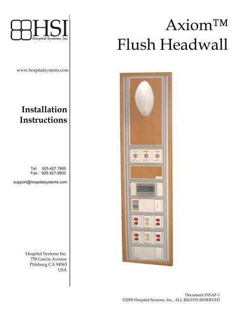
Introduction:<br />
The <strong>Hospital</strong> <strong>Systems</strong>, <strong>Inc</strong>. <strong>Axiom</strong> Flush <strong>Headwall</strong> is made to order <strong>for</strong> this project. Each headwall<br />
consists of the rough-in bracket and the pre-wired and pre-piped headwall that is particular to each<br />
location or type.<br />
Be<strong>for</strong>e attempting to install, please read and understand all of the instructions. In particular please<br />
refer to the final approved submittal drawings as they will take precedence over these instructions<br />
Note: Two types of units are addressed in this instruction bulletin.<br />
A) units that terminate below the ceiling line [Page 3]<br />
B) units that terminate at the ceiling line [Page 10]<br />
Basic Steps <strong>for</strong> Installing the Axom <strong>Headwall</strong>s<br />
� Prepare stud wall to accommodate headwall<br />
� Mount the rough-in bracket within the wall cavity<br />
� Install medical gas lines at locations shown on approved submittal drawings<br />
� Install electrical and communication conduit as shown on approved submittal drawings<br />
� Install drywall and finish building wall<br />
� Install <strong>Axiom</strong> Flush <strong>Headwall</strong><br />
� Install all electrical and communication wiring and make appropriate connections<br />
� Connect medical gas piping<br />
� Test, close, and clean<br />
Do NOT use powered screwdrivers on devices or coverplates.<br />
Stripped holes or screw heads are NOT covered by warranty<br />
<strong>Installation</strong> <strong>Instruction</strong>s <strong>for</strong> the Flush <strong>Axiom</strong> <strong>Headwall</strong> [Doc INSAF-1] Page 2 of 16<br />
©2009 <strong>Hospital</strong> <strong>Systems</strong>, <strong>Inc</strong>., ALL RIGHTS RESERVED
A. <strong>Axiom</strong> Flush <strong>Headwall</strong>s that terminate BELOW the ceiling line<br />
Preparation of the stud wall<br />
Determine the height and centerline <strong>for</strong> the headwall from the approved submittal drawings. Mount a<br />
saddle (sill) at 9⅛” (230 mm) above the floor. For horizontal opening see dimensions on approved<br />
submittal drawings. See Figure 1 <strong>for</strong> detail.<br />
Refer to approved submittal drawings <strong>for</strong> actual opening dimensions<br />
Mounting of the rough-in bracket<br />
Figure 1<br />
The rough-in bracket locates the electrical, communication, and medical gas entrances at the top of the<br />
headwall. The rough-in bracket is screwed to the front of the vertical studs. The vertical location of the<br />
bracket is shown on the approved submittal drawings See Figure 2.<br />
Figure 2<br />
<strong>Installation</strong> <strong>Instruction</strong>s <strong>for</strong> the Flush <strong>Axiom</strong> <strong>Headwall</strong> [Doc INSAF-1] Page 3 of 16<br />
©2009 <strong>Hospital</strong> <strong>Systems</strong>, <strong>Inc</strong>., ALL RIGHTS RESERVED
Installing the Medical Gas Lines<br />
Medical Gas Lines will enter the <strong>Headwall</strong> through the top-center. The headwall will accommodate ½”ID<br />
lines <strong>for</strong> Oxygen and Medical Air, and ¾”ID <strong>for</strong> Vacuum. Note: please refer to the approved submittal<br />
drawings to ensure that no changes have been made <strong>for</strong> this project. Lines are to be stubbed down the wall<br />
cavity, and through the notch in the rough-in plate. The stub is to be 15” (380mm) below the rough-in plate.<br />
The installer will need to leave some vertical movement to allow the installation of a coupling. Medical gas<br />
lines should be tested at this time. Please refer to Figure 3<br />
Installing the Electrical and Communication Conduit<br />
Conduits are terminated at the rough-in bracket. This plate will become the top of the headwall - thus<br />
conduits will not need to be removed and re-attached during installation. Refer to the approved shop<br />
drawings <strong>for</strong> correct locations. We suggest using tape [e.g. blue painters tape] over the ends of the conduit<br />
connectors to keep out any debris. Please refer to Figure 3.<br />
Be sure to follow the correct knock-out designations from the approved<br />
submittals or the conduit will end up in the wrong terminal compartment.<br />
Figure 3<br />
<strong>Installation</strong> <strong>Instruction</strong>s <strong>for</strong> the Flush <strong>Axiom</strong> <strong>Headwall</strong> [Doc INSAF-1] Page 4 of 16<br />
©2009 <strong>Hospital</strong> <strong>Systems</strong>, <strong>Inc</strong>., ALL RIGHTS RESERVED
Drywall and Wall Finishes<br />
Drywall contractor will now install drywall. Be sure that the edge of the drywall does not protrude into the<br />
prepared cavity, and that no excess drywall or taping compound is left within the cavity. See Figure 4.<br />
Building wall can now be completed.<br />
Figure 4<br />
Installing the <strong>Axiom</strong> Flush <strong>Headwall</strong><br />
After the building wall finishes have been applied, the <strong>Headwall</strong> is now ready to install. Bring it into<br />
the area, and remove it from the carton. While still lying on its back remove the top access panel.<br />
[Remove the gray snap-in trim, thus exposing the screws that retain the access panel.]<br />
Be sure to keep the snap-in trim and screws in a safe place until you<br />
re-install the panels.<br />
Remove the snap-in trim from the aluminum trim around the outside edge of the headwall<br />
Be sure to keep the snap-in trim in a safe place until you attach the<br />
headwall to the building wall.<br />
<strong>Installation</strong> <strong>Instruction</strong>s <strong>for</strong> the Flush <strong>Axiom</strong> <strong>Headwall</strong> [Doc INSAF-1] Page 5 of 16<br />
©2009 <strong>Hospital</strong> <strong>Systems</strong>, <strong>Inc</strong>., ALL RIGHTS RESERVED
Apply clear calking onto the back of the edge trim and lift the <strong>Headwall</strong> and insert it into the wall<br />
cavity. See Figure 5<br />
Figure 5<br />
Screw through the holes provided in the extrusion trim around the edge of the headwall. [Through the<br />
trim, the drywall and into the studs and track.] Replace snap-in trim See Figure 6<br />
Figure 6<br />
Electrical and Communication Wiring and Cables<br />
Pull electrical and communication wiring into the appropriate terminal compartments. The rough-in<br />
bracket has now become the top of the terminal compartments. Connect the incoming wires to the pigtails<br />
or terminal strips provided in the headwall. Communication wiring should go through the<br />
terminal compartment directly to the device that it will serve. A pull cord has been provided.<br />
<strong>Installation</strong> <strong>Instruction</strong>s <strong>for</strong> the Flush <strong>Axiom</strong> <strong>Headwall</strong> [Doc INSAF-1] Page 6 of 16<br />
©2009 <strong>Hospital</strong> <strong>Systems</strong>, <strong>Inc</strong>., ALL RIGHTS RESERVED
Connecting the Medical Gas Lines<br />
Connect the medical gas lines. All brazing must be completed according the NFPA 99 and local codes.<br />
Test all medical gas lines and brazed joints according to NFPA-99 and local codes.<br />
The inert gas (i.e. N2, CO2), used in brazing, must not overheat the gas<br />
outlets. (Suggestion – have inert gas flow through and away from the<br />
outlet.) Damage to the outlet due to overheating is NOT covered by<br />
warranty.<br />
All piping and medical gas outlets in the headwalls are debris-free.<br />
Please use care when blowing down the system piping that no debris<br />
comes into the headwall as damage to the medical gas outlet ‘O’ rings<br />
may occur. Damaged outlets are NOT covered by warranty<br />
Nurse Call and Other Communication Devices<br />
Install devices per the installation instructions of the device manufacturer. Mounting holes are drilled<br />
and tapped <strong>for</strong> 6-32 screws.<br />
Note: <strong>for</strong> telephone and/or data jacks, we have provided a module holder and coverplate. These<br />
holders will accommodate standard RJ-11, and RJ-45 modules. DO NOT INSTALL standard wall box<br />
plates. Additional holders and cover plates as well as modules (in various colors, and blanks) are<br />
available from <strong>Hospital</strong> <strong>Systems</strong>.<br />
<strong>Installation</strong> <strong>Instruction</strong>s <strong>for</strong> the Flush <strong>Axiom</strong> <strong>Headwall</strong> [Doc INSAF-1] Page 7 of 16<br />
©2009 <strong>Hospital</strong> <strong>Systems</strong>, <strong>Inc</strong>., ALL RIGHTS RESERVED
Re-installing the Access Panel<br />
All access panels <strong>for</strong> the same type and size of headwall are interchangeable. Note that the panels must<br />
be re-inserted in the same position and orientation as removed to insure that all of the holes are in line.<br />
Be sure to center the access panel so that the trim will fit evenly all-around<br />
Insert the screws and then snap in the trim. See Figure 7<br />
Do NOT use powered screwdrivers. Stripped holes or screw heads are<br />
NOT covered by warranty<br />
Figure 7<br />
<strong>Installation</strong> <strong>Instruction</strong>s <strong>for</strong> the Flush <strong>Axiom</strong> <strong>Headwall</strong> [Doc INSAF-1] Page 8 of 16<br />
©2009 <strong>Hospital</strong> <strong>Systems</strong>, <strong>Inc</strong>., ALL RIGHTS RESERVED
Final Test<br />
Medgas outlets: Complete the testing as per NFPA-99.<br />
Electrical<br />
devices:<br />
Cleaning<br />
Test electrical receptacles and other devices per local code<br />
and general practices.<br />
Use a soft cloth with non-abrasive cleaner (i.e. 409 or Windex) to remove dirt and fingerprints.<br />
<strong>Installation</strong> <strong>Instruction</strong>s <strong>for</strong> the Flush <strong>Axiom</strong> <strong>Headwall</strong> [Doc INSAF-1] Page 9 of 16<br />
©2009 <strong>Hospital</strong> <strong>Systems</strong>, <strong>Inc</strong>., ALL RIGHTS RESERVED
B. <strong>Axiom</strong> Flush <strong>Headwall</strong>s that terminate AT the ceiling line<br />
Preparation of the stud wall<br />
Determine the height and centerline <strong>for</strong> the headwall from the contract drawings. Mount a saddle (sill)<br />
at 9⅛” (230 mm) above the floor. For horizontal opening see dimensions on approved submittal<br />
drawings. See Figure 1 <strong>for</strong> detail.<br />
Mounting of the rough-in bracket<br />
Figure 1<br />
The rough-in bracket locates the electrical, communication, and medical gas entrances at the top of the<br />
headwall. The mounting bracket is screwed to the front of the vertical studs. The bottom of the roughin<br />
bracket must be in the same plane as the ceiling line. See Figure 2.<br />
Figure 2<br />
<strong>Installation</strong> <strong>Instruction</strong>s <strong>for</strong> the Flush <strong>Axiom</strong> <strong>Headwall</strong> [Doc INSAF-1] Page 10 of 16<br />
©2009 <strong>Hospital</strong> <strong>Systems</strong>, <strong>Inc</strong>., ALL RIGHTS RESERVED
Installing the Medical Gas Lines.<br />
Medical Gas lines will enter the <strong>Headwall</strong> through the top-center. The headwall will accommodate<br />
½”ID lines <strong>for</strong> Oxygen and Medical Air, and ¾”ID <strong>for</strong> Vacuum. Note: please refer to the approved<br />
submittal drawings to ensure that no changes have been made <strong>for</strong> this project. Lines are to be stubbed<br />
down the wall cavity, and through the notch in the rough-in plate. The stub is to be 15” (380mm) below<br />
the rough-in plate. The installer will need to leave some vertical movement to allow the installation of<br />
a coupling. Medical gas lines should be tested at this time. Please refer to Figure 3<br />
Installing the Electrical and Communication Conduit<br />
Conduits are terminated at the rough-in bracket. This plate will become the top of the headwall - thus<br />
conduits will not need to be removed and re-attached during installation. Refer to the approved shop<br />
drawings <strong>for</strong> correct locations. We suggest using tape [e.g. blue painters tape] over the ends of the<br />
conduit connectors to keep out any debris. Please refer to Figure 3.<br />
Be sure to follow the correct knock-out designations from the approved submittals, or<br />
the conduit will end up in the wrong terminal compartment.<br />
Figure 3<br />
<strong>Installation</strong> <strong>Instruction</strong>s <strong>for</strong> the Flush <strong>Axiom</strong> <strong>Headwall</strong> [Doc INSAF-1] Page 11 of 16<br />
©2009 <strong>Hospital</strong> <strong>Systems</strong>, <strong>Inc</strong>., ALL RIGHTS RESERVED
Drywall and Wall Finishes<br />
Drywall contractor will now install drywall. Be sure that the edge of the drywall does not protrude<br />
into the prepared cavity, and that no excess drywall or taping compound is left within the cavity. See<br />
Figure 4.<br />
Figure 4<br />
Installing the <strong>Axiom</strong> Flush <strong>Headwall</strong><br />
The <strong>Headwall</strong> is now ready to install. Bring it into the area, and remove it from the carton. While still<br />
lying on its back remove the top access panel. [Remove the gray snap-in trim, thus exposing the screws<br />
that retain the access panel.]<br />
Be sure to keep the snap-in trim and screws in a safe place until you re-install the panels.<br />
Remove the snap-in trim from the aluminum trim around the outside edge of the headwall<br />
Be sure to keep the snap-in trim in a safe place until you attach the headwall to the<br />
building wall.<br />
<strong>Installation</strong> <strong>Instruction</strong>s <strong>for</strong> the Flush <strong>Axiom</strong> <strong>Headwall</strong> [Doc INSAF-1] Page 12 of 16<br />
©2009 <strong>Hospital</strong> <strong>Systems</strong>, <strong>Inc</strong>., ALL RIGHTS RESERVED
Apply clear calking onto the back of the edge trim and lift the <strong>Headwall</strong> and insert it into the wall<br />
cavity. See Figure 5<br />
Figure 5<br />
Screw through the holes provided in the extrusion trim around the edge of the headwall. [Through the<br />
trim, the drywall and into the studs and track.] Replace snap-in trim See Figure 6<br />
Figure 6<br />
Electrical and Communication Wiring and Cables<br />
Pull electrical and communication wiring into the appropriate terminal compartments. The rough-in<br />
bracket has now become the top of the terminal compartments. Connect the incoming wires to the pigtails<br />
or terminal strips provided in the headwall. Communication wiring should go through the<br />
terminal compartment directly to the device that it will serve. A pull cord has been provided.<br />
<strong>Installation</strong> <strong>Instruction</strong>s <strong>for</strong> the Flush <strong>Axiom</strong> <strong>Headwall</strong> [Doc INSAF-1] Page 13 of 16<br />
©2009 <strong>Hospital</strong> <strong>Systems</strong>, <strong>Inc</strong>., ALL RIGHTS RESERVED
Connecting the Medical Gas Lines<br />
Connect the medical gas lines. All brazing must be completed according the NFPA 99 and local codes.<br />
Test all medical gas lines and brazed joints according to NFPA-99 and local codes.<br />
The inert gas (i.e. N2, CO2), used in brazing, must not overheat the gas outlets.<br />
(Suggestion – have inert gas flow through and away from the outlet.) Damage to the<br />
outlet due to overheating is NOT covered by warranty.<br />
All piping and medical gas outlets in the headwalls are debris-free. Please use care<br />
when blowing down the system piping that no debris comes into the headwall as<br />
damage to the medical gas outlet ‘O’ rings may occur. Damaged outlets are NOT<br />
covered by warranty<br />
Nurse Call and Other Communication Devices<br />
Install devices per the installation instructions of the device manufacturer. Mounting holes are drilled<br />
and tapped <strong>for</strong> 6-32 screws.<br />
Note: <strong>for</strong> telephone and/or data jacks, we have provided a module holder and coverplate. These<br />
holders will accommodate standard RJ-11, and RJ-45 modules. DO NOT INSTALL standard wall box<br />
plates. Additional holders and cover plates as well as modules (in various colors, and blanks) are<br />
available from <strong>Hospital</strong> <strong>Systems</strong>.<br />
<strong>Installation</strong> <strong>Instruction</strong>s <strong>for</strong> the Flush <strong>Axiom</strong> <strong>Headwall</strong> [Doc INSAF-1] Page 14 of 16<br />
©2009 <strong>Hospital</strong> <strong>Systems</strong>, <strong>Inc</strong>., ALL RIGHTS RESERVED
Re-installing the Access Panel<br />
All access panels <strong>for</strong> the same type and size of headwall are interchangeable. Note that the panels must<br />
be re-inserted in the same position and orientation as removed to ensure that all of the holes are in line.<br />
Be sure to center the access panel so that the trim will fit evenly all-around<br />
Insert the screws and then snap in the trim. See Figure 7<br />
Final Test<br />
Do NOT use powered screwdrivers. Stripped holes or screw heads are NOT covered by<br />
warranty<br />
Figure 7<br />
Medgas outlets: Complete the testing as per NFPA-99.<br />
Electrical<br />
devices:<br />
Test electrical receptacles and other devices per local code<br />
and general practices.<br />
<strong>Installation</strong> <strong>Instruction</strong>s <strong>for</strong> the Flush <strong>Axiom</strong> <strong>Headwall</strong> [Doc INSAF-1] Page 15 of 16<br />
©2009 <strong>Hospital</strong> <strong>Systems</strong>, <strong>Inc</strong>., ALL RIGHTS RESERVED
Cleaning<br />
Use a soft cloth with non-abrasive cleaner (i.e. 409 or Windex) to remove dirt and fingerprints.<br />
<strong>Installation</strong> <strong>Instruction</strong>s <strong>for</strong> the Flush <strong>Axiom</strong> <strong>Headwall</strong> [Doc INSAF-1] Page 16 of 16<br />
©2009 <strong>Hospital</strong> <strong>Systems</strong>, <strong>Inc</strong>., ALL RIGHTS RESERVED