Series PAVC Variable Volume Piston Pumps - Parker Hannifin ...
Series PAVC Variable Volume Piston Pumps - Parker Hannifin ...
Series PAVC Variable Volume Piston Pumps - Parker Hannifin ...

Create successful ePaper yourself
Turn your PDF publications into a flip-book with our unique Google optimized e-Paper software.
Catalog HY28-2662-CD/US<br />
<strong>Variable</strong> Displacement <strong>Piston</strong> <strong>Pumps</strong><br />
Control Options <strong>Series</strong> <strong>PAVC</strong> 33/38/65/100<br />
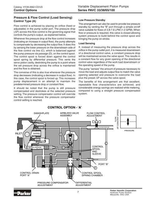
Pressure & Flow Control (Load Sensing)<br />
Control Type (A)<br />
Flow control is achieved by placing an orifice (fixed or<br />
adjustable) in the pump outlet port. The pressure drop<br />
( P) across this flow control is the governing signal that<br />
controls the pump’s output, as explained below.<br />
Whenever the pressure drop at the flow control increases<br />
(indicating an increase in output flow), the pump attempts<br />
to compensate by decreasing the output flow. It does this<br />
by sensing the lower pressure on the downstream side of<br />
the flow control via line (C), which is balanced against<br />
the pump pressure via passage (D), on the control spool.<br />
The control spool is forced down against the control<br />
spool spring by differential pressure. This vents the<br />
servo piston cavity, destroking the pump to a point where<br />
the set pressure drop across the orifice is maintained<br />
and the flow is obtained.<br />
The converse of this is also true whenever the pressure<br />
drop decreases (indicating a decrease in output flow). In<br />
this case, the control spool is forced up. This increases<br />
pump displacement in an attempt to maintain the<br />
predetermined pressure drop or constant flow.<br />
It should be noted that the pump is still pressure<br />
compensated and destrokes at the selected pressure<br />
setting. The pressure compensator control will override<br />
the flow control whenever the pressure compensator<br />
control setting is reached.<br />
INLET<br />
BARREL<br />
PISTON<br />
PISTON<br />
SERVO PISTON<br />
CONTROL DRAIN<br />
PORT “A”<br />
SWASHPLATE<br />
CONTROL OPTION - ‘A’<br />
AIRBLEED VALVE<br />
ASSEMBLY<br />
D<br />
PRESSURE COMPENSATOR<br />
ADJUSTMENT<br />
E<br />
Low Pressure Standby<br />
This arrangement can also be used to provide low pressure<br />
standby by venting the “B” port through a simple on/off<br />
valve suitable for flows of 3.8-7.6 LPM (1-2 GPM). When<br />
flow or pressure is required, this valve is closed allowing<br />
system pressure to build behind the control spool and<br />
bringing the pump on-stroke.<br />
Load Sensing<br />
If, instead of measuring the pressure drop across the<br />
orifice in the pump outlet port, it is measured downstream<br />
of a directional control valve, a constant pressure drop<br />
will be maintained across the valve spool. This results in<br />
a constant flow for any given opening of the directional<br />
control valve regardless of the work load downstream or<br />
the operating speed of the pump.<br />
The pump “senses” the amount of pressure necessary to<br />
move the load and adjusts output flow to match the valve<br />
opening selected and pressure to overcome the load<br />
plus the preset P across the valve spool.<br />
The benefits of this arrangement are that excellent,<br />
repeatable flow characteristics are achieved, and<br />
considerable energy savings are realized while metering,<br />
compared to using a straight pressure compensated<br />
system.<br />
7<br />
FLOW CONTROL<br />
ADJUSTMENT<br />
CONTROL<br />
SPOOL<br />
AND<br />
SLEEVE<br />
SIGNAL LINE<br />
CONTROL SPOOL<br />
SPRING CHAMBER<br />
DIFFERENTIAL<br />
ADJUSTMENT<br />
F<br />
SYSTEM PRESSURE<br />
C<br />
PORT “B”<br />
FLOW<br />
(AT CONSTANT SPEED)<br />
PRESSURE<br />
<strong>Parker</strong> <strong>Hannifin</strong> Corporation<br />
Hydraulic Pump Division<br />
Marysville, Ohio USA