
You also want an ePaper? Increase the reach of your titles
YUMPU automatically turns print PDFs into web optimized ePapers that Google loves.
<strong>V6</strong> <strong>Aurelia</strong> <strong>Mania</strong><br />
This article is about Lancia’s quite famous all alloy <strong>V6</strong> engine, that got so gloriously applied in their “common” <strong>Aurelia</strong> models and<br />
particularly so short after WW2 lacking Marshall stimulation Lancia’s post war resurrection was quite sensational for the early fifty’s.<br />
The basic structure of the world’s first series produced all alloy <strong>V6</strong> engine, seen in its time in connection to some later <strong>V6</strong> designs and<br />
some bore/stroke, rod/rad, conrod length, different multivalve, cam height, big end diameter and compression relations are considered<br />
in accordance to the knowhow of the period and sometimes even down to its disadvantages. During the intensive rebuild of my #3900<br />
<strong>Aurelia</strong> B-20 GT 2500 6 th Series Coupé, I noticed surprising construction details causing me to report some remarks and while work on<br />
the block slowly advances, you will enjoy my sequenced information about how it all gets out of hand in a jolly way, even sometimes<br />
not quite free of mild exaggeration. One might experience my writing about the car as a temporary substitute for not riding it.<br />
NOVEMBER 2008<br />
Last addition made October 2010 by Francosporto himself.<br />
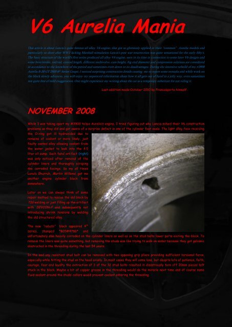
While I was taking apart my #3900 telaio <strong>Aurelia</strong>‟s engine, I tried figuring out why Lancia solved their <strong>V6</strong> construction<br />
problems as they did and got aware of a surprise defect in one of the cylinder foot seals. The light alloy face receiving<br />
the O-ring got ill hydroxided due to<br />
remains of coolant or more likely, just<br />
faulty casted alloy allowing coolant from<br />
the water jacket to leak into the 4.5<br />
liter oil sump. Such fatal artifact (right)<br />
was only noticed after removal of the<br />
cylinder liners and thoroughly scraping<br />
the corroded facings. So my all times<br />
Lancia Ghurruh, Martin Willems, got me<br />
another engine cylinder block from<br />
somewhere.<br />
Later on we can always think of some<br />
repair method to rescue the old block by<br />
TIG welding or just filling up the artifact<br />
with DEVCON-F and subsequently not<br />
introducing shrink tensions by welding<br />
the old structured alloy.<br />
The new “rubato” block appeared 4 th<br />
series, stamped *B20#4786* and<br />
unfortunately also heavily corroded on the cylinder liners as well as on the stud bolts lower parts exiting the block. To<br />
remove the liners was quite something, but removing the studs was like trying to walk on water because they got galvanic<br />
obstructed in the threading during the last 54 years.<br />
In the end any resistant stud bolt can be removed with two opposing grip pliers providing sufficient torsional force,<br />
especially while hitting the stud on the head axially. In most cases they will come lose, but despite lots of patience, faith,<br />
courage, fear and loyalty the extraction of 3 of the 32 stud bolts resulted in disastrously torn off 20mm pieces left<br />
stuck in the block. Maybe a bit of copper grease in the threading would do the miracle next time and of course some<br />
fluid sealant around the studs‟ collars would prevent coolant entering the threading.
Coincidentally I saw one of Martin‟s B-20 blocks (similar as above) standing in a corner of his “Walhalla” being ill from<br />
the same disease having non removable bolts, surprisingly at the same positions: the front right side near the oil stick.<br />
The cause of the similarity is not clear, but besides me being quite good at drilling, in this case it is again clearly shown<br />
why always every job on these old engines appear to be unbelievably time consuming. So drilling is what we are going to do<br />
…… with a vertical drilling machine !!!! Hand held drilling tools will certainly bring disaster …. If someone should be looking<br />
for disaster, grab your hand tool ……<br />
The following part will exclusively be discussed to suit those of you, who do not know how to remove a torn off bolt from<br />
an irreplaceable and certainly quite expensive engine part, without destroying the surrounding machined surfaces. DO<br />
TRY THIS AT HOME FIRST …… with some useless carburetor or obsolete Fiat 126 engine carter !!!<br />
So be smart and start properly by supporting your <strong>V6</strong>-block with a 30° jig securing the threading to be absolutely<br />
vertical. Always mark the centre of the resisting part by using a center punch and proceed drilling with a small freshly<br />
grinded sharp drill using quite some axial force at low rpm. You are not in a hurry and you don‟t want to remove an<br />
overheated piece of broken drill from a smoking hole, clogged with hot steel grindings. So advance sequentially from<br />
2,5mm by 0,5mm intervals to about 5,5mm to a depth of 6 to 7mm removing the chips in time. Start all over to a depth<br />
of 12 to 14mm followed likewise to 20mm avoiding penetration of the end of the bolt with a small drill in a small hole.<br />
Because now your hole is wide enough to use a stronger drill, it is now possible to remove almost all of the remaining<br />
“pièce de resistance” except for the threading. Maybe with the help of a “Dremel” tool the entrance of the threading<br />
can be cleared a bit more to make access for a (above) #3 M8 thread cutter, this time obviously operated by hand in<br />
your vertical drilling machine to be followed by the #2 and finally #1 hand thread cutter. Operating an electric powered<br />
thread cutter into a blind hole at high speed could be quite disastrous.<br />
Sorry me being the Ghurruh here ………… of course everyone already knew this !!!!
With our studs and liners removed from the block it is now possible to level the surfaces facing the head gaskets and<br />
the water pump with my simple glass plate/sandpaper method. With 8mm a sufficient stable glass plane ensures a<br />
perfect level surface by pressing evenly on waterproof sandpaper. Sanding crosswise (below) enables you to check your<br />
progress in sanding locally. Where the sanding marks are too light more pressure is needed on the glass plate and you will<br />
notice the surface being a bit higher around the edges of the threaded holes, due to 54 years of tension on the studs<br />
resulting in some creep in the alloy. Do not press to hard on the edges of either surface and often refresh your #150 to<br />
# 100 waterproof sandpaper to avoid differences in sanding ability because of locally worn paper. When the surface is<br />
evenly sanded everywhere, your surface only shows some last slightly sanded areas left indicating your leveling being<br />
finished. In most cases you will also notice quite some damage marks from heroic overconfident “mechanics” from the<br />
past.<br />
In the early fifty‟s the <strong>V6</strong> engine layout was believed<br />
to be impossible because of heavy vibrations, difficult<br />
to balance until then. Vincenzo‟s son in law and brilliant<br />
designer Francesco de Virgilio (FdV) managed to get<br />
the balancing mathematics right and had his thesis<br />
accepted after a historic dispute with the top of the<br />
Turin Polytechnico. As there were almost no industrial<br />
standards for parts, Lancia had to design and produce<br />
most parts themselves for instance resulting in three<br />
different length of stud bolts. In our case new M8<br />
studs fitted quite nicely in the refreshed threads,<br />
except for five formerly over refreshed threads some<br />
solution was needed avoiding helicoils. So because M9 has the same 1,25 windings/mm and our tool factory anyhow has to<br />
make such exotic studs, we decided to use the M9 solution. The only disadvantage is the cylinder head casings need to be<br />
over bored to 10,5mm accepting the 9mm studs, again with your vertical milling machine. For the purists amongst us, it<br />
would always be possible milling back the upper part to M8 metric fine threads, missing the advantage of streamlining<br />
the bolts locally at their crossing through the intake canals without making them weaker than the M8 originals. Maybe<br />
sometimes Martin Willems will make these 32-piece M9 stud bolt sets available, because even my wife Karin could easily<br />
do the hand cutting up to M9 threading after having burred the M8 hole to 7,3mm. Use #3 first and feel the tool<br />
entering the old thread. Later on with the Flaminia‟s M10 studs all of this was avoided.
December 2008<br />
Because of the New Years Eve drinking at Martin‟s we all got to his hide out at Emmer Compascuum (NL) bringing<br />
sufficient Italian Nastro Azzurro beer, Salame di Friuli and Oliebollen Olandesi and for the occasion William had all<br />
bearings placed and measured. The four main bearing caps are coded by center punching and are related to the numbered<br />
bearing supports crossing the block (above) which are taking all the resultant forces from the crankshaft and carefully<br />
notice the multi compartment structure of this timelessly modern designed block.<br />
William (Wim in dutch left) got all valves fitted into the<br />
Francosporto 3C streamlined ported heads. (discussed in “Why<br />
not 3C”)<br />
The oil scheme (below) shows oil pressure coming through the oil<br />
filter, feeding all 4 main bearings first as well as the upper<br />
bearing of the vertical oil pump/distributor shaft and the chain<br />
tensioner. Vertically from the main bearings on, pressure is fed<br />
to the #1, 2 and 3 camshaft bearings. All left and right 6 rocker<br />
bearings are conveniently pressure fed from the most forward<br />
#1 camshaft bearing. The cam followers get oiled by return oil<br />
from the rocker case along the pushrod ducts. The rear camshaft<br />
bearing and the 90° cog wheels get oil fed from the #3 bearing<br />
through the camshaft, the last part being hollow. At high revs the surplus oil in the rocker case flows back through two<br />
return ducts in between each 3 cylinders,<br />
while the cams themselves are lubricated by<br />
waist oil from the big ends.<br />
My digipic (next page top) shows a nice<br />
possibility to attach an external oil cooler line<br />
to the right side of the block and is pressure<br />
fed from the #2 main bearing. Avoiding full<br />
oil pressure on the cooling line could be quite<br />
possible by using the (11) waist exit from the<br />
oil pressure control valve inside the block.<br />
The advantage will be that no pressure<br />
control is needed at the return of the line for<br />
instance to the right side of the sump. Maybe<br />
sometimes a similar oil filter bracket with an
external low pressure waist oil connection will be made available by Martin<br />
Willems suiting sporty <strong>Aurelia</strong> drivers at track days. Oil cooling at colder<br />
weather can easily be adjusted by (partly) taping the cooler.<br />
January 2009<br />
In the meantime my set of new M9<br />
“oversized” stud bolts (below) got<br />
available, with two extra pieces for<br />
testing purposes. The old M8 stud<br />
on the left got murdered of course<br />
by the two grip pliers trick. Spanner<br />
14 still fits to M9 nuts because they<br />
are made from 8mm high M8 models.<br />
The testing is to verify 3,3kgm<br />
torsional strength on the partially<br />
grinded stud bolts at their exposure<br />
into the intake ducts achieving at<br />
least some improved aerodynamics .<br />
Each cylinder heads‟ three intake canals are not at all similar and here we are very basically looking at the result of the<br />
struggle for space in the design. The position of the studs are most decisive for the design of the intake and exhaust<br />
canals and got even worse with the push rods in the way. The choice for push rod distribution even in the early fifty‟s<br />
makes no sense to me at all, considering the <strong>Aurelia</strong>‟s sporty character and high price. Someone knew for sure easy<br />
excess for decarbonizing the cylinder heads was a reason, while someone else knew for sure that simplicity in design was<br />
the reason. Neither is plausible, because in general Lancia designs always lead to the most complicated and nicest<br />
possible technical solutions, always being the least profitable. So this leaves us one last possibility: Gianni Lancia himself<br />
ruled in favor of the pushrod distribution that had proven quite well in his one off V8 model from his “Polytechnico” days<br />
and got his most creative engineer FdV probably instructed to better apply this “cheaper” solution. In the early fifty‟s it<br />
was indeed not a bad choice at all, compared to the market, but ... below you see the M9 studs in situ as well as their<br />
crossing the shifted intake ducts.
Later on some more grinding was made on these three stud bolt as well as at the opposing light alloy side of the most<br />
only needed few attention. Also notice<br />
disturbed left canal achieving better air flow. The middle canals‟ stud still has<br />
the flowed 3C adapted canals by Francosporto looking quite different compared to<br />
the original. (see also “Why not 3C ”)<br />
to be modified, while the right one<br />
The 1953 Lancia upgrade to 2.5 liter <strong>V6</strong> single (1C) Weber DCZ40 carbureted setup was only possible by rearranging the<br />
obstructing adjacent valve stems by rotating the combustion chambers. At the time BMW‟s also struggled with this<br />
problem designing a shorter block and called it “gekreuzte ventielen” crossed valves. So as a result the Tuscany Hills like<br />
swirling intake and exhaust ducts got a little straightened, but Lancia left the position of all studs as they were. Why<br />
steeper valves in lower combustion chambers were not considered will always be unclear. Only with the redesigned<br />
<strong>Aurelia</strong> engines for the Flaminia‟s the Pesenti-Lancia factory realized such thermally more efficient valve setting<br />
resulting into more or less roof shaped combustion chambers.<br />
March 2009<br />
Last week I got surprised by Geoffrey Goldberg‟s (GG) email asking “What about your 3C setup, please translate because<br />
my Dutch is nonexistent ” (........ at the time this site was only in Dutch) So I explained the site being about my<br />
experimental 3C setup only to check its advantages compared to the original as well as to the extraordinary expensive<br />
Nardi setup. By exploring this twin Weber DCZ40 after sales upgrade kit at Martin‟s Living Museum, I realized that still<br />
quite some tricks (discussed in “Why not 3C”) could be done on the original single carburetor job boosting the cylinders<br />
inhalation. During his many years of <strong>Aurelia</strong> tuning GG experienced the intake valves being the most restrictive, because<br />
them getting more rpm inhibiting mass at larger diameters. Agreeing I would add of course Lancia‟s choice for pushrod<br />
distribution being the cause of frivolous curved ducts<br />
and worse on top of all the Vittorio Jano styled<br />
(discussed in “AR 8C <strong>Mania</strong>”) vestibule like passages<br />
between the valve seat and the valve guide boss,<br />
resulting in two disturbances for the fast moving gas<br />
stream.<br />
So one quite sharp angle exists at the rather swirly<br />
intake manifold flowing into a bowl shaped chamber<br />
around the valve stem, followed by a second opposite<br />
deviation passing the valve seat into the even more angled<br />
cylinder. Obviously designers seem not to have been fully<br />
aware of the total resistance they were creating with<br />
multiple changing gas flow direction. The exhaust side being similar except for an additional passing around a disturbing<br />
stud bolt, resulting in the so called D-shape porting ………<br />
Such gas flow process is heavily influenced by valve angles and basically the <strong>Aurelia</strong>‟s 1930‟s porting more or less got<br />
dealt with in Lancia‟s D Series engines of course without the pushrods, but still with too many stud bolts in<br />
disadvantageous positions. In the early fifties Lancia‟s “Reparto Corse” clearly did realize some of those restrictions<br />
considering setups of FdV‟s B-54 as well as Ettore Zaccone Mina‟s (EZM) B-110 “prova” designs both already tested from<br />
1952 onwards. So frankly spoken Lancia would have made more sense and certainly immortal history by installing their<br />
sporty B-54 dry sump SOHC engine into all B-20 <strong>Aurelia</strong>‟s from early 1953 onwards and sell them as the next stage<br />
upgrade GT Super Sports cars. It would have been a testimony of marketing skill using Lancia‟s advanced technical<br />
knowhow profitable.
Or instead even imagine for the 1953 season, Lancia sensationally would<br />
have been offering these 170pk B-54 SOHC 3C long stroke (crankshaft<br />
similar to B-20 78x85,5) dry sump engines, fitted with stunning<br />
“Elektron” cylinder heads to selected <strong>Aurelia</strong> clientele only. No adapted<br />
crank/rod system was even needed considering the structure of the<br />
compact (right) crankshaft being ridged enough having 60mm main shaft<br />
journals and 50mm crank pins, considering D-25 sports cars, even being<br />
almost twice as powerful, used about the same crankshaft dimensions<br />
with of course much more ribbing on the block providing structural<br />
reinforcement. Theoretically<br />
with the big ends more (left)<br />
overlapping the main bearings, once more an important design element, easily<br />
resulting into short stroke dimensioned, more compact, lighter and more rev<br />
hungry crankshafts, got ignorantly overlooked.<br />
FdV‟s B-54 works drawing (below) shows both SOHC‟s, driven by one long duplex chain directly from the crankshaft‟s<br />
front side sprocket, leaving the large sprockets on the camshafts for their 50% RPM reduction. The alternator and<br />
water pump/fan unit are V-belt driven from the nose of the crankshaft. The vertical oil pump/distributor shaft is driven<br />
by skew gears from the inside of the left SOHC. Lubrication was quite straight forward with the crankshaft having the<br />
usual B-20 journals. Oil pressure was horizontally distributed to all camshaft journals as well as rockers and cams<br />
through the hollow camshafts and rocker shafts. The<br />
twelve valve B-54 engine left surplus space between<br />
each exhaust valve to the period‟s obligate twin<br />
sparkplug ignition system. Very noticeable should be<br />
the ideal situated stud bolts and the unusual small<br />
valve included angle being quite ahead of its time as<br />
well as camshafts being positioned pretty low in the<br />
heads actuating rather angled and spring assisted<br />
rockers crossing over the camshaft. Attention was<br />
given to all water jackets and distributing galleries<br />
now being quite tight suggesting a much faster coolant<br />
circulation compared to the B-20 block. All intake<br />
canals now have been quite straightened<br />
accommodating three double barrel (Solex 32 ? PA11)<br />
carburetors.
To my opinion the B-54 design could well have been the initial design FdV had in mind for his sporty B-20 <strong>Aurelia</strong> project<br />
all along. We will never know, because FdV is not anymore amongst us living and Gianni Lancia still alive but definitely not<br />
ever wants to be interviewed about Lancia & Co Automobili. But in ‟52 and ‟53 on the contrary Gianni had a great time<br />
with his “<strong>Aurelia</strong> da Corsa” (above)<br />
project, only to pull out of GT Class<br />
“competizione” in favor of Sports Car<br />
racing, obviously forced by certain AR<br />
protests against Lancia‟s not having<br />
homologated their all aluminum “da<br />
Corsa” B-20 body‟s and consequently we<br />
now understand the B-54 dry sump<br />
SOHC engines, even in thin steel B-20<br />
chassis, being quite impossible to get it<br />
all homologated in time, without<br />
overstressing the factory production<br />
capacity building such a substantial<br />
amount of production competition cars.<br />
In fact a fifty‟s GB newly imported B-<br />
20 Coupé was price tagged only £200<br />
less compared to a basic Rolls Royce.<br />
Along with FdV‟s B-54 project Lancia‟s<br />
other promising designer Ettore<br />
Zaccone Mina was working on a second<br />
<strong>V6</strong> “prova” design (right) designated B-<br />
110. In fact both “prova” designs had<br />
“competizione” type D Series cars in<br />
mind. Why EZM didn‟t choose for, if<br />
only slightly B-20‟s deviating<br />
crank/bore/conrod relations is unclear<br />
to me, because the off the shelf<br />
160mm conrods from the (115hp) B-20,<br />
despite being very rugged, were<br />
unnecessarily his first choice. These<br />
comparatively long conrods heavily<br />
narrowed down the DOHC and 3C (triple<br />
carbs) advantages of this almost square<br />
80,5x81,5 block still producing 187hp.<br />
For this initially all blank “prova” design<br />
exercise EZM could well have chosen<br />
for the more radical 83,0x77,0 short<br />
stroke variant, providing lower mean<br />
piston speeds (mps) and even, with up to<br />
145mm shortened conrods a more<br />
dynamic intake gas flow cycle should be<br />
possible since pistons accelerate earlier<br />
and faster. See about this my 3e<br />
experimental phase further below.<br />
Quite interesting to discover in EZM‟s works drawing (above) are the Vittorio Jano AR (Alfa Romeo) style mushroom<br />
actuated valves with spring coils under pretty much the same valve angles compared to the B-54 design as well as the<br />
disadvantageous second oil ring below the gudgeon pin. Clearly no provisions were considered for oversized cylinder liners<br />
to accommodate later capacity changes. Note also twin sparkplugs being quite accessible from between the DOHC‟s,<br />
providing ignition through a not shown distributor on the rear side of the left intake camshaft. The lubrication system is<br />
basically B-54 similar and probably to simplify valve distribution, a pair of gears oddly over reduce RPM from the<br />
crankshaft to a duplex chain driving all four camshafts minimizing wear and tear on the chain, only to accelerate the<br />
camshafts to the correct RPM at last with relatively smaller camshaft sprockets also enabling the bonnet lower over the<br />
block. At the crankshaft‟s rear a rudimentary flywheel drives the alternator by V-belt. The water pump is directly driven<br />
from the crank‟s front while the oil pump is gear driven downwards pairing the cam distribution driving gear. Each intake<br />
manifold‟s vacuum is balanced by horizontal ducts but unfortunately again shows about 35mm carburetor shift compared
to the valve porting of the front right cylinder, because of large float chambered carburetors taking more space than<br />
available.<br />
Despite all these efforts Gianni Lancia,<br />
though maybe not fully aware of all the<br />
restrictive factors inside his “prova”<br />
blocks, unfortunately decided not to<br />
proceed with even alone his beautiful dry<br />
sump B-54 design. He must have seen<br />
that the increased power output mainly<br />
got produced because of the better<br />
porting only made possible by absence of<br />
the pushrods. The increased RPM<br />
possibilities involving the OHC valve<br />
actuation probably had less influence<br />
because of earlier discussed flow<br />
resistance around the valves<br />
unfortunately increasing squarely to<br />
higher rpm‟s.<br />
More restrictive factors in both designs, besides limited viscous oil behavior in all main journals, big ends, piston guiding<br />
and second oil rings, would be the 15mm too long standard 160mm conrods together with the pistons free space to the<br />
crankshaft of about some 18mm and the unnecessary low position of the Ø20mm gudgeon pin in each piston, leaving about<br />
another 7mm unused in general dimensioning. Now one realizes why these bulky crank balancing lumps (see AR 8C crank in<br />
“8C <strong>Mania</strong>”) should be kept small in diameter obviously to be related to the stroke. All together this waisted space could<br />
well have been used advantageously for shorter 145mm conrods with B-20 style 26mm wide journals (today common on<br />
most VW Golf) subsequently<br />
decreasing the total engine‟s<br />
height with 25mm (a good inch<br />
lower all together !!!). Moreover<br />
in all the periods high<br />
performance engines negatively<br />
working second oil rings were<br />
ignorantly applied. Not only by<br />
Lancia & Co, but surprisingly<br />
after „56 these rings were<br />
obsolete in all GP engines after<br />
some 25 years, at least since<br />
Jano‟s 1932 AR 8C 2300<br />
discussed in “8C <strong>Mania</strong>” of<br />
ignoring and misunderstanding<br />
the nature of these rings. (see<br />
also “Camshaft <strong>Mania</strong>” ) At last<br />
in the 1956 GP season Ferrari<br />
most gloriously seized the<br />
World Championship with the (ex Lancia) D-50 V8 GP car, however without the second oil rings as noticeable in the<br />
digipic (above) from “Classic Racing Engines” by Karl Ludvigsen 2001 and at the fabulous D-50 stunning with original<br />
Lancia badge, steering wheel and factory stamped<br />
parts in the “Museo Ferrari” (right) at Maranello,<br />
second GP Car from the entrance and quite<br />
emotionally choking finding the real car there.<br />
Both FdV and EZM have been struggling with intake<br />
canal layout from the carburetors on to the valves<br />
avoiding unnecessary curved canals. After all it was<br />
quite well known straight canals having less<br />
resistance at higher revs, so I got rather surprised
discovering the B-110‟s carburetors being too wide<br />
with their large float chambers needing more space on<br />
the block related to each pair of cylinders causing<br />
them to shift up to 35mm towards the right front,<br />
only solved with (already discussed above) more<br />
unwanted swirly intake ducts. Earlier with the Willy<br />
Claes B-20 Liege-Rome-Liege (above a replica) works<br />
3C rally car setup, Lancia managed to eliminate most<br />
carburetor shifting by arranging the three twin choke<br />
32 PA11 Solex narrow body carburetors oblique to<br />
compensate partly for the 40mm difference between<br />
opposing big ends. According to Nigel Trow, being<br />
familiar with the car, the 3C setup was very drivable<br />
and gave great satisfaction.<br />
Only long crossed intake canals with D-50 like tilted<br />
(right) carburetors, would have been ideal to suit the B-<br />
54 maximally, but would be less advantageous for the B-<br />
110 lacking enough space between the inner DOHC cam<br />
banks. All together the automotive industry was very<br />
much in need of narrow carburetors, quite possible at<br />
the thought of these D-50 carbs also being specially<br />
produced to Lancia specification. Notice D-50 intake<br />
canals being perfectly straight also thanks to hair pin<br />
type valve springs allowing intake canals passing tighter.<br />
Later conversion to coil springs consequently needed<br />
more curving around the valve guide bosses and indeed<br />
today intake ducts are more axial adapted to the valve<br />
stems.<br />
After all such reasoning one can<br />
question Lancia‟s ‟53 technical<br />
competition level being sufficient at<br />
all or did the “Reparto Corse” ran out<br />
of development potentials to properly<br />
engage the AR, Mercedes, Maserati,<br />
or Ferrari competition at the highest<br />
level or was the racing department<br />
just following the easy way? Did<br />
Vittorio Jano ran out of options and<br />
what had been the cause of the<br />
controversial family drama causing<br />
FdV‟s “promotion” to the Diesel<br />
department particularly in relation to<br />
the developing D-50 design.<br />
Remarkable in EZM‟s own data table<br />
(right) about B-110 up to D-100<br />
characteristics, you will notice mostly<br />
the same crank/rod relations are<br />
applied. Obviously the strong Jano<br />
influences were still spooking around<br />
in the Reparto Corse offices.
EZM slowly tended to under square bore/stroke engines, but for the<br />
D-50A surprisingly 6,55mm longer conrods were tried. For the D-<br />
100 design (left) the old still relatively long 135mm conrods<br />
returned unmotivated, meaning nothing new was introduced and so<br />
what should have been its testing all about.<br />
Mechanically and historically reasoning about longer or shorter<br />
conrods, the simplifying of the 1876 (above) four stroke Otto<br />
patented engine by Maybach and Daimler had certainly been all<br />
important to the developing automotive industry. The flat steam<br />
engine type Otto piston was connected to a two peace articulated driving system with a steam era typical sliding joint in<br />
between, formerly enabling double action push/pull steam pistons. The piston together with its fixed push/pull rod and<br />
sliding joint got brilliantly transformed into one internal jointed piston to articulate directly with its crank‟s conrod.<br />
Actually the gudgeon pinned piston was<br />
invented but at the time “Deutz<br />
Motoren AG” only could cope with such<br />
transverse vectors coming from small<br />
ends by using very long and consequently<br />
extremely heavy dimensioned driving<br />
connecting rods. Obviously longer<br />
conrods (left) (rod/rad 13.5:1) produce<br />
lower transverse forces resulting in<br />
lower piston resistance to the cylinder.<br />
By this improvement on Otto‟s<br />
stationary four stroke patent, Daimler<br />
and foremost Maybach managed to make the internal combustion engine successful to the automotive and aircraft<br />
industry. Avoiding such long rpm restrictive rods were tried in the Borsig GmbH design (below) resulting in a much faster<br />
and very much smoother running streamliner with short conrods and V arranged small Ø 300mm cylinders.
Back to Gianni‟s sports car racing<br />
program. Note the dedicated Lancia<br />
mechanics (right) changing plugs at the<br />
‟53 “Panamericana” to the slightly<br />
(0,965) under square D-24. Triple<br />
carbs are 46mm DCF3 Webers feeding<br />
the 3.1 liter 6200rpm DOHC <strong>V6</strong> engine.<br />
Lancia most gloriously won also the ‟54<br />
“Panamericana” with their all new under<br />
square (0,915) 3464cc D-25 redlined<br />
at 6500rpm. Oddly rod length<br />
increased with 4mm to 164mm with<br />
1mm heavier 25mm gudgeon pins<br />
illustrating (or maybe defying) the<br />
Daimler Maybach heritage discussed<br />
above. Power output increased to<br />
280hp being twice the Willy Claes<br />
factory car. Because of oil pump<br />
starvation and the 4 th main journal<br />
being molten at 7000rpm during the<br />
‟54 Sebring, Lancia had to give up their<br />
leading position jeopardizing<br />
“Panamericana” aftermath hopes.<br />
Extensive search for solutions like 3mm increased 68mm main journals, larger capacity oil scavenging and pressure<br />
pumps, larger oil content and altered oil coolers, resulted finally the car to produce the intended 280hp at 6900rpm. The<br />
end fifty‟s short stroke Ray Petty Manx Nortons, being fully comparable in capacity “parziale” could be raced safely at<br />
10.000rpm producing over 60hp … on roller bearings. Thanks to modern design, metallurgic and lubrication knowledge<br />
today, high revving Ø108mm pistoned heavily under square Ducati‟s with ultra short pistons and conrods are reliably<br />
decorating our roads. Lancia was only just looking for such knowledge<br />
at the time ... in the wrong direction and probably blinded by<br />
“concurrenti ” the dead end street was not recognized!<br />
Whenever my 3rd test project will show the 3.5:1 rod/rad relation<br />
engine with (common VW Golf) 145mm conrods (right) running in a<br />
lowered B-20 block (below) is uncertain unless I‟m to hit the<br />
lottery‟s jackpot, but would be very interesting to learn about such<br />
more dynamic gas exchange caused by faster and earlier<br />
accelerating pistons. The right bank of the block has been virtually<br />
lowered only to show the difference compared to the left normal<br />
side. It would be a lot of work, but can be done by TIG welding a new edge 15mm lower followed by some machining to<br />
receive shortened cylinder (below left) liners. All other experiments are totally reversible except for this stage needing<br />
welding and machining, but all tests clearly<br />
could have been done in 1953 by Lancia<br />
Reparto Corse themselves and finally could<br />
have been presented as B-20 upgrades.<br />
Even the D-24‟s relatively high rod/rad<br />
relation of 3.7:1 being higher to the ‟53 model<br />
got exceeded by the later 3.3:1 ultra short<br />
stroke Ferrari Dino 246 <strong>V6</strong> with yet these<br />
low design features and higher power output.<br />
After all my reasoning about rod/rad/crank<br />
related options one could additionally review<br />
our <strong>V6</strong> block still being of the two valve type.
Enlarging valves as an option to improve performance is limited because they always have to fit in the available space,<br />
which will be larger for short stroke/large bore cylinder heads. In our relatively narrow B-20 spherical combustion<br />
chamber larger inlet valves easily could be installed (at a major overhaul) by exchanging the existing 43mm valve seats<br />
for 4mm larger rings fitting common Fiat 130 TC 43.5mm valves (as below) only to overlap the Ø 72mm squish edge a<br />
little requiring each piston to be grinded for clearance. Actually such enlargement from 35mm into 38mm would also be<br />
possible for exhaust valves. My experimental 3C conversion and triple siamesed exhaust system certainly would perform<br />
better and are at least an interesting next level test. In the meantime I feel the lottery coming my way very closely !! ??<br />
Additional advantage could come<br />
from improvement on aerodynamics<br />
around the new seat edges resulting<br />
in less resistant gas flow by<br />
reshaping the entrance to the inside<br />
edge of the valve seats. See graphic<br />
design (right) projected in my B-20<br />
cylinder head with its valve seats<br />
already removed only indicating<br />
dimensional position. Unfortunately<br />
3 sets of spare cylinder heads are<br />
lacking to me as this would have<br />
been ideal for evaluation.<br />
Please feel free using the idea to<br />
your advantage and report me about<br />
your experiences.<br />
Having discussed the limited<br />
possibilities to improve on our B-20<br />
engine power output one got to be<br />
creative. Lately at Martin Willems<br />
Living Museum I had to be on guard,<br />
because of the danger for getting<br />
mental institutionalized because of<br />
my <strong>Aurelia</strong> <strong>Mania</strong> or my healthy over creativeness, easily considered by non insiders<br />
as mental distortion. On the contrary it is big fun thinking fifties design level in<br />
honor of the great Francesco de Virgilio. The question why Lancia did not notice and<br />
certainly did not apply developments seen at other constructors but Ferrari will<br />
probably never be known. Quoting Nigel Trow: Yes that‟s a good question, but you‟ve<br />
got to realize that at Lancia‟s not always there has to be a reason ?? For instance<br />
using Morini‟s 3 valve setup (right) as a non patented possibility to improve easily on<br />
lighter inlet valve operation with a bonus 30% increased inlet area was never<br />
considered by senior constructors in the Reparto Corse Offices.
Even at Bugatti‟s those advantages<br />
were used in their very successful<br />
type 35 sports cars. Oddly the very<br />
large (right) 46mm inlet valves of<br />
the Lancia D-25, Maserati 250-F<br />
and likewise 52mm for the Ferrari<br />
Dino 246 or even worse 54mm for<br />
the Maserati 61 Birdcage were not<br />
at all considered being the end of 2<br />
valve technology development at<br />
increased rpm‟s.<br />
Even related to the cylinder bore these huge valves<br />
suffer great inertial problems related to their mass,<br />
obviously only to be solved with three or four valve<br />
setups. Another disadvantage will be such huge valves<br />
strongly deflecting the gas stream earlier hitting the<br />
cylinder wall nearby instead of streaming along into the<br />
cylinder. (left and below)<br />
If for instance FdV would have been given the<br />
assignment (by Gianni Lancia himself of course !!!) to<br />
explore the established Lancia design traditions for<br />
dusty common generalities and research for alternative<br />
solutions to improve on their racing program, he at least<br />
would have been stumbling over the above discussed<br />
items, being the theoretical genius he was. If so, Gianni Lancia certainly could have been showing himself off as the<br />
gentleman like Lancia godfather and family man, but he ruled against his brother in law getting him deported to the<br />
diesel department due to an unknown and certainly unsolvable supreme argument.<br />
Maybe FdV commented him on short sighted mainly empirical<br />
orientated development out of the Jano pleasing corner and<br />
consequently about inefficient spent financial resources<br />
related to the family company shares? Or was it about the<br />
ancient clash between large ego‟s concerning FdV‟s supreme<br />
presentation of <strong>V6</strong> crank balancing mathematics once<br />
defended at the Torino Polytechnico against at least one of<br />
the professors being professor Fessia. (Cementi era designs)<br />
In 1956 even Soichiro Honda bought a believed to be 3 valve FB Mondial<br />
125cc GP racer, considered as state of the art, from the Fratelli Boselli<br />
personally for study purposes only.<br />
So imagine Gianni buying a<br />
twin carburetor 250cc single<br />
cylinder “tres valvole” 3V<br />
Morini GP engine (right)<br />
personally from Alfonso<br />
Morini himself (left) only to<br />
get it studied . . . . and had it<br />
enlarged 200% as a 500cc<br />
test bed fitting his D-25<br />
program launching Lancia into<br />
the multi valve league.
Morini even developed their very successful 3V GP engine into 4V (left)<br />
upgrading their existing machinery obviously at low cost securing<br />
compatibility for another year. From 1960 on all Honda competition<br />
machines were 4V setup only. Mike Hailwood was their biggest star rider<br />
and together with Nobby Clark the three of us drank a lot of beer one night<br />
at the ‟65 Francorchamps GP meeting.<br />
Giugno 2009<br />
At Martin Willems‟ overhaul department Wim got my engine completed with M9 studs, new liners and 9.2 pistons. Note<br />
the high piston heads installed and machined retention groove in the liner‟s flanges providing more grip to the head<br />
gaskets. Between the cylinders notice two oil drain canals.<br />
Wim (right) is installing the nuts on the right cylinder<br />
head‟s studs, while the gasket on the left bank is still<br />
visible.<br />
Wim and B. were amazed (below) finding the water pump<br />
fitting correctly between the 3C manifolds. Wait till<br />
they find out the distributor fitting tight against the<br />
#3 carb‟s left barrel !!
Later on Martin‟s modified beautiful Italian Malioli type (right) exhaust<br />
manifold as intended for his own B-20 was tried just for fun and looks,<br />
but my own Francosporto exhaust manifold better would be<br />
constructed to the engine mounted in the car. So a lot of work still<br />
remains to be finished.<br />
But...<br />
But only because I ever want to experience the characteristics<br />
of a high performance B-54 like SOHC <strong>Aurelia</strong> <strong>V6</strong> and since I<br />
never will be allowed to drive The Louwman Collection‟s sole<br />
surviving (right) original D-23, I have to build a SOHC <strong>Aurelia</strong><br />
myself and respecting historics I have to limit the design to the<br />
era‟s design level. So digital fuel injection, toothed belts or KKK<br />
exhaust turbo compressors are non options and in honor of<br />
Lancia‟s Francesco de Virgilio (FdV) I would be very pleased to<br />
produce only one super valuable “Diciotto” 18V SOHC “prova”<br />
upgrade kit as a commercial attractive alternative between B-20 and D-20 cars, which in 1953 easily could have been<br />
manufactured by Lancia‟s themselves at least suiting the rich Italian Noble‟s racing at Sunday afternoons finishing<br />
always top five. Initially I referred to this project as my 4th test phase, but the plan quickly got developed into a full<br />
“diciotto” B-54 like project. Important to the design will be the complete upgrade kit‟s necessity to get installed by the<br />
same skilled mechanics who used to work on B-20‟s without irreversible alterations to the block.<br />
The selected clientele<br />
would have been kept<br />
competitive for some more<br />
years and even following<br />
Morini‟s recipe also next<br />
level 4V DOHC upgrading<br />
would suit later model<br />
development like Sport<br />
Zagato Flaminia‟s …… if only<br />
Lancia would have been<br />
thinking more commercially<br />
related to model efficiency<br />
indeed.<br />
Such wooden chest would have been marked with yellow or light blue<br />
template painted lettering “Lancia Automobili Torino” and next<br />
lined with “ ricambi competizione” and “ tipo B-543” containing 6<br />
forged flat pistons, 2 pre assembled three valve cylinder heads with<br />
camshaft installed, 1 chain box (below), 1 double sprocket replacing the<br />
large camshaft sprocket, 1 duplex chain, 3 small chain sprockets, 1<br />
chain tensioner with sprocket, 1 set 32 piece M9 studs, 6 separate<br />
intake manifolds, 3 Weber IDA 48 R carbs (left), 2 Ø43mm left and<br />
right MW-exhaust manifolds, 1 oil cooler with lines, 1 enlarged oil<br />
sump, 1 gasket set and some not thought of small parts.
If I can do such design on the corner of my desk certainly the Lancia design team also could have done it in 1952 and<br />
above all I never could discover any reason why Gianni did not recognize any commercial profit in producing small badges<br />
of D-20 and D-23 cars after getting obsolete as his next move. Additionally quite profitable could have been providing<br />
customers with package included proper maintenance and circuit assistance organized by the Reparto Corse exploiting<br />
fully Lancia‟s technical advanced position like they showed they were well capable of at the ‟52 and ‟53 “Panamericana”.<br />
The beautiful D-20 (above) was “THE” stunning ”want to have” car in ‟52. Within the first season it got obsolete second<br />
best to the factory‟s D-23, which in fact were chopped D-20‟s. In the early fifty‟s seller‟s market consequently selling<br />
such level racing equipment could well provide commercially profitable finance supporting properly Lancia‟s sports car<br />
program. Compared to Enzo Ferrari clearly there<br />
must have been a difference in Gianni Lancia<br />
approaching technical as well as commercial innovative<br />
management. Even our own Prince Bernhard of the<br />
Netherlands had to pay cash collecting his Ferrari<br />
212, while on the contrary Gianni‟s regular Old Boys<br />
Lancia Racing Bunch for many years just used these<br />
valuable cars probably without paying too much or not<br />
at all, while the lucky factory drivers (flying D-24<br />
right at full speed through Brescia) even got paid !<br />
............ bold, but for sure glorious it was.<br />
Despite Gianni Lancia obviously being familiar with the factory‟s<br />
nearing bankruptcy, we always have to be grateful to him for the<br />
glorious achievements made by his cars.<br />
His famous Luglio 26 th 1955 “abdicazione” and consequently selling<br />
(right) the Reparto Corse to Enzo Ferrari (complete with Agnelli‟s<br />
blessing) for a few Italian Lira would not have been necessary at all,<br />
if only the proper commercial attitude would have been present<br />
earlier. Ferrari‟s “avocado” in dark suit (below) was present arranging<br />
the deal. No it‟s not Willy Neubauer !<br />
At that sad black day for the dedicated Lancia<br />
workers all D-50 cars, parts and prototypes<br />
were moved (below) to Maranello. Gianni sold<br />
his mother‟s (Adèle) and his own Lancia shares<br />
to the fortunate cement manufacturer Carlo<br />
Pesenti avoiding the factory getting closed and
about 5.000 workers out of jobs.<br />
Thanks to the following “Cementi”<br />
era we still can enjoy our Flavia‟s,<br />
Fulvia‟s and Flaminia‟s today.<br />
So in the meantime while Martin<br />
Willems is reassembling my faithful<br />
(below) originally light blue #3900<br />
B-20 <strong>Aurelia</strong>, I had plenty of time to<br />
review my probe design (former page above), only testing available<br />
space for SOHC distribution and 3V layout. It appeared difficult<br />
situating the exhaust cam<br />
between (A) the two intake<br />
cams (in) because a central<br />
exhaust cam would<br />
interfere to both inner edges of the<br />
cup type cam followers. So an offset<br />
(right) rocker actuated by a third<br />
eccentric (B) cam would be a solution.<br />
The SOHC only can be situated<br />
between the two inner rows of stud<br />
bolts, because two intake valves<br />
between the two studs (left) take too<br />
much space with their adjacent valve<br />
springs.<br />
Anyhow dimensioning 3V SOHC 3 carburetor setup definitely seemed possible with the heads fitting the existing stud<br />
bolt positions. But realizing in retrospect the machining of cam cup seats could become too complicated and expensive at<br />
service overhauls I had to rework the design. So less bulky valve springs and finger followers were discussed at Martin‟s<br />
during teatime enabling a strait and much lighter exhaust rocker actuated by a central (A) cam. Distribution had to be<br />
chain driven considering general Lancia design practice and could only be installed nondestructively by maintaining the<br />
existing camshaft. A small sprocket fixed in front of the existing large camshaft sprocket offsets my second<br />
distribution chain enough to the front providing free passage to the higher situated left and right camshaft quite like<br />
the well known B-110 setup.<br />
December 2009<br />
In review of the Giugno (June) 2009<br />
initial design a second setup (right) was<br />
made getting all valves and rockers in<br />
appropriate positions and angles. A<br />
wooden mould model had to be as<br />
versatile as possible to serve multiple<br />
purposes. As long as it could be taken<br />
apart in segments later correction<br />
stayed possible and so we went<br />
modular or segmented (below) for easy<br />
access and shaping internal water<br />
canals as well as producing water<br />
passage kernels for the foundry. In<br />
case of serious mistakes or design<br />
changes only a few faulty segments<br />
need renewal.
Zuffenhausen” solution (below) shows us some<br />
of the problems FdV must have encountered at<br />
the time.<br />
In the actual dimensioned setup (above right)<br />
the exhaust rocker is tested for position and<br />
dimension. Later on intake canals got positioned<br />
Later the fixed intake manifolds got separated for easy access to<br />
the porting and unfortunately the cam cover level seems to<br />
interfere to maximum (above) straightened down draught intake<br />
canals. The weight of several parts are in the setup as well.<br />
Due to each exhaust valve being under heavy thermal load shaping<br />
coolant canals around the exhaust area (left) will be very delicate,<br />
because two plugs, two stud bolts and one oil drain canal<br />
concentrate around each exhaust valve obstructing effective close<br />
coolant passages because of their casings being rather bulky all<br />
together. Maybe later some additional forced fresh coolant have<br />
to be injected in poorly circulating<br />
areas to solve this bottleneck.<br />
The revised design (left) shows the<br />
swirly curved intake canals<br />
necessary for usual DCZ40 type<br />
carburetors redesigned for Weber<br />
IDA carburetors with their float<br />
chambers between the throats or<br />
even more favorable, ideal but<br />
unfortunately 2.5 times more<br />
expensive pair of 46 IDA 3C triple<br />
throat Webers. So an “out of
steeper and got almost straight by situating the rocker cover gasket some higher at camshaft level. Note the ball joint<br />
cam followers giving camshafts to shift more towards the exhaust valve resulting in a more compact exhaust rocker.<br />
Actual valves and cam followers with their fitting ball joints (above) are shown compared to the 1:1 design.<br />
In the sixties Ludwig Apfelbeck (left) also designed a SOHC 3V upgrade kit<br />
for pushrod VW Beetles and got honored some 50 years later by the actual<br />
construction of his aged design described in his book “Wege zum<br />
Hochleitungs-Viertaktmotor”, Motorbuch Verlag 1997. Camshaft distribution<br />
by “modern” toothed belts and digital fuel injection were unknown to him,<br />
but however additionally used by the “Apfelbeck team”. Particularly look for<br />
the fabulous 3D graphics of the 3valve layout at their website<br />
http://members.home.nl/r.vd.meulen/demo.htm<br />
Besides the design of the B-543 Diciotto Prova upgrade kit, it would be<br />
quite exiting to honor FdV likewise by the actual construction of .. .. ..<br />
In the meantime (summer 2010) work on the mould model is progressing nicely. Stud bolt nuts have to remain accessible<br />
without removal of camshafts. Spark plug positions and water passages are not interfering. Shaping coolant passages<br />
Viva Gianni<br />
. . and how versatile these<br />
fabulous <strong>Aurelia</strong>‟s are !!!<br />
around the exhaust area is quite<br />
complicated not to interfere with the twin<br />
plug casings as well as the oil return canals<br />
and stud bolt casings.<br />
Have patience, to<br />
be continued ………
Francosporto‟s Related Links :<br />
<strong>Aurelia</strong> <strong>Mania</strong> : http://www.lanciaaurelia3c.nl/aurelia%20mania.html<br />
Classic thinking : http://www.lanciaaurelia3c.nl/classic denken.html<br />
Unfortunately some parts are still in dutch but digipics are great !<br />
Why not 3C : http://www.lanciaaurelia3c.nl/toch%20maar%203c.html<br />
Home : http://www.lanciaaurelia3c.nl/index.html<br />
Martin Willems : http://www.martinwillems.nl/ or http://www.b20.nl/<br />
DCNF40/<strong>Aurelia</strong>3C-manyfold : http://www.youtube.com/watch?v=Db8lBtvNjMM&feature=channel_page<br />
Vere Lancia Racing : http://www.lanciaracing.com<br />
VCR engine video : http://www.mce-5.com/downloads/MCE-5_2008_GB.mpg<br />
MCE-5 site : http://www.mce-5.com/introduction/index.htm<br />
BMW efficient dynamics : http://bmw.co.uk/bmwuk/efficient_dynamics/bc/homepage<br />
Thesis TDI Spider LM : http://www.fiatlanciathesispidertdilemans.it/ita/home.html<br />
The official MB Photo & Film Site : http://members.chello.nl/m.been6/index/Mijn_albums/Mijn_albums.html<br />
The Apfelbeck 3V project : http://www.apfelbeck.nl/<br />
Jay Leno‟s Garage : http://www.jaylenosgarage.com/video/index.shtml<br />
Email Francosporto : aurelia3c@kpnplanet.nl<br />
don‟t hesitate, even for a small question or a tiny winy suggestion …………………………<br />
- Have fun in reading all of this –<br />
Francosporto<br />
-/-