
Create successful ePaper yourself
Turn your PDF publications into a flip-book with our unique Google optimized e-Paper software.
Introduction to <strong>UHV</strong> <strong>Design</strong> to <strong>UHV</strong> <strong>Design</strong><br />
Welcome to the <strong>UHV</strong> <strong>Design</strong> product<br />
catalogue. As specialists in <strong>UHV</strong> motion<br />
and heating products, <strong>UHV</strong> <strong>Design</strong> sets<br />
the pace in innovative product development for the<br />
vacuum industry.<br />
Our primary focus is to provide high-quality lowmaintenance<br />
manipulation solutions for vacuum<br />
applications.<br />
Excellence is assured through in-house control of<br />
the entire process from design, to manufacture,<br />
assembly, test and after sales support. A customerorientated<br />
approach combined with a desire to<br />
achieve unrivalled product excellence is key to our<br />
continued success.<br />
<strong>UHV</strong> <strong>Design</strong> has developed and manufactured<br />
vacuum manipulation solutions for over 15 years.<br />
In that time it has accumulated a ‘productionproven’<br />
product range, positioning <strong>UHV</strong> <strong>Design</strong><br />
at the forefront of high and ultra high vacuum<br />
manipulation.<br />
It also ensures technical<br />
knowledge and<br />
expertise is maintained<br />
within the company.<br />
As well a standard<br />
portfolio of products,<br />
much of <strong>UHV</strong> <strong>Design</strong>’s<br />
heritage is based upon<br />
working closely with the customer to offer specifi c<br />
custom solutions.<br />
Today a high percentage of business is generated<br />
by the company’s ability to adapt and modify<br />
standard products to meet the needs of specifi c<br />
applications.<br />
Over the years <strong>UHV</strong> <strong>Design</strong> has developed ideas in<br />
conjunction with some of the most prestigious and<br />
forward thinking scientifi c and technical institutions.<br />
Many of these products have proved so popular<br />
www.uhvdesign.com sales@uhvdesign.com Tel:+44(0)1323 811188
that they have become standard product ranges<br />
in their own right. It is this continual<br />
process of development, review and<br />
improvement that has enabled <strong>UHV</strong><br />
<strong>Design</strong> to stay at the forefront<br />
of vacuum technology for<br />
over a decade.<br />
Working closely with<br />
our customers has not<br />
only enabled us to<br />
assemble a genuinely<br />
cutting edge product<br />
portfolio but also gain<br />
valuable insight into<br />
the challenges that<br />
vacuum manipulation<br />
can sometimes involve.<br />
By taking an innovative<br />
approach, <strong>UHV</strong> <strong>Design</strong><br />
often eliminate problems<br />
that have become common<br />
place in standard manipulation<br />
product ranges. For example, the<br />
kinematic movements of our LSM<br />
<strong>UHV</strong> <strong>Design</strong><br />
Z shift range, the magnetic coupling technology<br />
of our linear and rotary probes, and the<br />
choice of materials, bearings and<br />
sealing methods in all our product<br />
ranges, have led to a range of<br />
signifi cant improvements and<br />
developments in the vacuum<br />
industry.<br />
The rapidly changing face<br />
of research technology<br />
has led to the creation of<br />
new scientifi c disciplines<br />
that rely upon the<br />
capability to move<br />
components precisely<br />
and reliably within ultra<br />
clean environments.<br />
<strong>UHV</strong> <strong>Design</strong> is proud to<br />
have supplied manipulation<br />
solutions to pioneering<br />
laboratories around the world<br />
specialising in Nanosciences,<br />
Synchrotron and Beamline<br />
applications and many others.<br />
<strong>Design</strong> Manufacture Cleaning Assembly<br />
Tel:+44(0)1323 811188 sales@uhvdesign.com www.uhvdesign.com<br />
<strong>UHV</strong> <strong>Design</strong>
Contents<br />
Section 1 Rotary Drives MagiDrive rotary feedthroughs 001<br />
Section 2 Shutters Rotary source shutters, viewport shutters, linear shutters 039<br />
Section 3 Push Pull Drives Linear and linear/rotary push-pulls 047<br />
Section 4 Sample Transfer Tools Linear and linear/rotary PowerProbes and wobble sticks 055<br />
Section 5 Linear Motion and Port Aligners Linear shift mechanisms and port aligners 079<br />
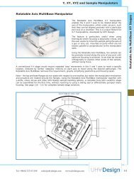
Section 6 Y, XY, XYZ and Sample Manipulators Y-Shifts, MultiBase, MultiStage, MultiCentre, cryostats 103<br />
Section 7 Sample Heater/Deposition Stages EpiCentre deposition manipulation stages 127<br />
Section 8 Heater Modules <strong>UHV</strong> heater modules 145<br />
Section 9 MicroProducts Micro- Flanges / Shifts / Drives / Feedthroughs 149<br />
Section 10 <strong>UHV</strong> Flanges <strong>UHV</strong> fl ange range 161<br />
Section 11 Bellows Edge-welded bellows series 165<br />
Section 12 Goniometers Custom multi-axis solutions 171<br />
Section 13 Motion Controllers DC and stepper motor control options 175<br />
Section 14 Synchrotron Solutions Beam alignment probe 183<br />
Section 15 Customised Solutions Bespoke and special builds 187<br />
www.uhvdesign.com sales@uhvdesign.com Tel:+44(0)1323 811188
Section 1<br />
Rotary Drives<br />
Introduction to the MagiDrive Range 002<br />
Torque Level Graphs 002<br />
Selecting Your Drive 003<br />
Standard ‘Solid’ Body Drives<br />
Low/medium Torque<br />
MD10 Range 008<br />
MD16/ MD19 Range 011<br />
MD20/ MD21 Range 014<br />
Medium Torque<br />
MD25 Range 017<br />
MD35 Range 020<br />
High Torque<br />
MD64 Range 023<br />
MD100 Range 026<br />
Hollow Body Drives<br />
Introduction to Hollow MagiDrive Range 028<br />
MD35H Hollow Range 030<br />
MD64H Hollow Range 033<br />
MD100H Hollow Range 036<br />
Custom MagiDrives 038<br />
Magnetic Rotary Drives<br />
sales@uhvdesign.com www.uhvdesign.com 001<br />
Magnetic Rotary Drives
Magnetic Rotary Drives<br />
002<br />
Magnetic Rotary Drives<br />
Introduction to the<br />
MagiDrive range<br />
The MagiDrive range of rotary feedthroughs enable<br />
rotation to be transferred into a vacuum system,<br />
using a stiff high fl ux magnetic coupling. This<br />
removes the need for bellows or sliding seals,<br />
and provides an extremely robust design, fully<br />
compatible with <strong>UHV</strong> environments. As testament<br />
to this, MagiDrives have been used successfully<br />
in demanding production environments for over a<br />
decade.<br />
The MagiDrive range is supplied with CF <strong>UHV</strong> fl anges<br />
as standard and are available in twelve sizes to<br />
match the fl ange and torque requirements of each<br />
application.<br />
The series includes unique hollow options, permitting<br />
services to be passed through the centre and also<br />
allows MagiDrives to be ‘stacked’ one atop another<br />
providing up to four axes of independent rotation<br />
(see page 028).<br />
A number of actuation methods are available from<br />
manually driven units, to pneumatic and motorised<br />
drives. Additional options include the use of state-ofthe<br />
art ceramic bearings for ultra-clean applications,<br />
such as semiconductor production. MagiDrives are<br />
compact, bakeable to 250ºC and offer true <strong>UHV</strong><br />
performance.<br />
MagiDrive concept<br />
Using the latest magnetic materials technology, a<br />
large number of high fl ux magnetic fi elds interlock<br />
inner and outer rotating assemblies through a solid<br />
stainless steel enclosure.<br />
This enclosure or ‘vacuum envelope’ is manufactured<br />
from one-piece ensuring vacuum integrity. The high<br />
density of interlocking fi elds ensures exceptionally<br />
high torsional rigidity.<br />
MagiDrives used in excess of their torque rating<br />
simply release their ‘magnetic grip’ and lock back<br />
onto the next magnetic pole. This protects the<br />
drive and whatever it is driving from incurring any<br />
damage, thereby avoiding expensive maintenance.<br />
MagiDrives offer high precision rotation with zero<br />
angular backlash under low load and acceleration.<br />
All drives are fi tted with magnetic shielding.<br />
www.uhvdesign.com sales@uhvdesign.com Tel:+44(0)1323 811188
Selecting your MagiDrive<br />
The drives have been divided into solid and hollow<br />
body variants. The main difference being that the<br />
hollow version allows you to pass services down<br />
through the drive body, or stack multiple drives<br />
together allowing up to four axes of independent<br />
rotation, (see page 028 for more detail).<br />
The drives are subsequently organised by torque<br />
level and fl ange size as depicted in the chart<br />
opposite, which can be used to fast-track to the<br />
drive that meets your needs.<br />
Each section then includes detailed specifi cations, a<br />
part number generator and dimensional drawings.<br />
The following section includes a comprehensive<br />
description of MagiDrive sizes, actuation methods,<br />
shaft and bearing options.<br />
MagiDrive range<br />
The MagiDrives are available in twelve sizes, to suit<br />
the torque and fl ange size requirements for the<br />
majority of applications.<br />
MagiDrives are manufactured as standard with CF<br />
<strong>UHV</strong> fl anges, from CF10 to CF100. Customised ‘O’<br />
ring fl anges are available upon request.<br />
The four largest MagiDrives are available in a ‘hollow’<br />
confi guration, terminating with a CF fl ange at the<br />
rear. This allows services to be passed through the<br />
drive, or an additional MagiDrive to be mounted<br />
to the rear, providing additional axes of concentric<br />
rotation. Up to four independent axes of rotation<br />
can be provided by combining the MD16, MD35H,<br />
MD64H and MD100H MagiDrives.<br />
This ‘stacking’ capability is typically used to provide<br />
simple solutions to sophisticated manipulation<br />
requirements, such as the provision of primary,<br />
azimuthal and tilt rotation of a sample.<br />
Tel:+44(0)1323 811188 sales@uhvdesign.com www.uhvdesign.com<br />
Magnetic Rotary Drives<br />
Standard manual actuation (T)<br />
Dual shaft (D)<br />
Calibrated thimble (CF, CB)<br />
Stacked MagiDrives<br />
003<br />
Selecting Rotary Drives
Selecting Rotary Drives<br />
004<br />
Magnetic Rotary Drives<br />
Actuation method<br />
The MagiDrive range is available with a variety of manual, pneumatic and motorised actuation methods.<br />
Manual actuation<br />
Code Item Description<br />
T Standard drive The standard manual drive.<br />
F Friction control An adjustable friction system enables the drive to hold its position<br />
when the desired position is reached. Resistance to turn is adjusted<br />
by tightening/ loosening a single screw located at the rear of the<br />
drive.<br />
B Brake A thumbscrew brake facility enables the drive to be locked in any<br />
position.<br />
BF Brake with friction<br />
control<br />
CF Calibrated thimble with<br />
friction control<br />
CB Calibrated thimble with<br />
brake<br />
For applications where a drive should have adjustable friction control<br />
as well as a brake facility.<br />
A calibrated thimble gives a visual indication of the drive position<br />
with one degree increments. It is fi tted with the friction control<br />
system as standard.<br />
As above but including the capability to lock the drive in any position.<br />
K Knurled end cap If a drive is intended for Manual actuation it may be convenient to<br />
utilise a knurled end cap. This affords the user a better grip when<br />
manually turning the drive thimble.<br />
D Dual shaft MagiDrives can be supplied with both input and output shafts. This<br />
allows the customer to retrofi t their own motorisation option or to fi t<br />
a position encoder.<br />
P Timing pulley A pulley is mounted on the end of the drive allowing users to install<br />
their own motor assembly.<br />
Pneumatic actuation<br />
Code Item Description<br />
RA Rotary actuator Pneumatically actuated MagiDrives are fi tted with an adjustable rotary<br />
actuator providing from 30-170 o sweep. Flow controllers enable input<br />
and exhaust to be throttled to control speed.<br />
RAI Rotary actuator with<br />
visual position indicators<br />
and reed switches for<br />
position feedback<br />
As above but fi tted with two reed switches to provide position feedback<br />
for system interlock facilities. This option also includes LEDs allowing<br />
the user to see the position of the shutter in open or closed states.<br />
www.uhvdesign.com sales@uhvdesign.com Tel:+44(0)1323 811188
Tel:+44(0)1323 811188 sales@uhvdesign.com www.uhvdesign.com<br />
Magnetic Rotary Drives<br />
Motorised MagiDrives can be driven with DC or stepper motors, and are available with a selection of motor<br />
and gearbox combinations to cover a wide range of load, speed and positioning requirements.<br />
Motors can be mounted either to the side (as shown below) or in-line with the drive, to suit the space available.<br />
Motors are easily removed for bakeout and have pre-set mounting brackets to ensure the correct re-alignment<br />
and belt tension is maintained when the motor is replaced.<br />
<strong>UHV</strong> <strong>Design</strong> offer a full range of motor controllers which are described on pages 175 - 181.<br />
Code Item Description<br />
Stepper Motors<br />
IS In-line stepper motor A co-axially mounted stepper motor providing minimum lateral<br />
footprint.<br />
ISS In-line stepper motor<br />
with switches<br />
SS Side mounted stepper<br />
motor<br />
SSS Side mounted stepper<br />
motor with switches<br />
DC Motors<br />
As above but with a rear disk and switch assembly, providing a datum<br />
point ‘home position’.<br />
A stepper motor mounted to the side of the drive.<br />
A side mounted stepper motor with a rear disk and switch assembly to<br />
provide a datum ‘home position’.<br />
ID In-line DC motors A co-axially mounted DC motor providing minimum lateral footprint.<br />
SD Side mounted DC motor A DC motor mounted to the side of the drive.<br />
Timing pulley (P) Side mounted stepper motor (SS)<br />
005<br />
Selecting Rotary Drives
Selecting Rotary Drives<br />
006<br />
Magnetic Rotary Drives<br />
Motorised MagiDrive gearing options<br />
Each motorised MagiDrive is offered with a range of gearbox options allowing a variety of torque and spin<br />
speed solutions to be offered as standard. Simply add the ‘Gear Option’ number you require to the MagiDrive<br />
part number as shown in each section. Special confi gurations are available on request.<br />
Drive Motor type Gear option Maximum output<br />
torque Nm<br />
MD10<br />
MD16<br />
MD19*<br />
MD20<br />
MD21*<br />
MD25<br />
MD35<br />
MD35H<br />
MD64<br />
MD64H<br />
In-Line DC (ID)<br />
In-Line stepper motor (IS)<br />
In-Line DC (ID)<br />
In-Line stepper motor (IS)<br />
Side mounted DC motor (SD)<br />
In-Line DC motor (ID)<br />
Side mounted stepper motor (SS)<br />
In-Line stepper motor (IS)<br />
Side mounted DC motor (SD)<br />
In-Line DC motor (ID)<br />
Side mounted stepper motor (SS)<br />
In-Line stepper motor (IS)<br />
Side mounted DC motor (SD)<br />
In-Line DC motor (ID)<br />
Side mounted stepper motor (SS)<br />
In-Line stepper motor (IS)<br />
Maximum output<br />
spin speed RPM<br />
1 0.04 363<br />
2 0.18 82<br />
3 0.18 44<br />
4 0.18 19<br />
1 0.04 1,800<br />
2 0.18 360<br />
3 0.18 113<br />
4 0.18 72<br />
1 0.2 230<br />
2 0.2 135<br />
3 0.3 70<br />
4 0.45/ 0.56* 42<br />
5 0.45/ 0.56* 21<br />
6 0.45/ 0.56* 8<br />
1 0.12 1000<br />
2 0.45 300<br />
3 0.45 150<br />
4 0.45 60<br />
1 0.7 213<br />
2 2.0 80<br />
3 2.4 40<br />
4 2.4 20<br />
1 0.4 320<br />
2 1.0 120<br />
3 2.0 60<br />
4 2.4 30<br />
1 1.0 500<br />
2 1.5 200<br />
3 2.0 80<br />
4 2.4 40<br />
1 1.0 500<br />
2 2.4 120<br />
3 2.4 60<br />
4 2.4 30<br />
1 0.8 175<br />
2 2.0 65<br />
3 3.5 33<br />
4 4.0 16<br />
1 0.4 320<br />
2 1.0 120<br />
3 20 60<br />
4 4.0 30<br />
1 1.0 500<br />
2 1.6 165<br />
3 2.0 66<br />
4 4.0 33<br />
1 1.0 500<br />
2 2.4 120<br />
3 4.0 60<br />
4 4.0 30<br />
1 3.8 235<br />
2 7.5 117<br />
3 10 48<br />
4 10 24<br />
1 2.0 440<br />
2 4.0 220<br />
3 10 88<br />
4 10 44<br />
1 4.5 160<br />
2 9.0 80<br />
3 10 32<br />
4 10 16<br />
1 2.5 300<br />
2 5.0 150<br />
3 10 60<br />
4 10 30<br />
www.uhvdesign.com sales@uhvdesign.com Tel:+44(0)1323 811188
Code Item Description<br />
X000 Stub shaft or spigot Dependant upon drive size.<br />
Tel:+44(0)1323 811188 sales@uhvdesign.com www.uhvdesign.com<br />
Magnetic Rotary Drives<br />
Shaft options<br />
Lower torque MagiDrives are offered as standard with short stub shafts for end users to connect to. They are<br />
also offered with a modular shaft assembly. This option provides an arbitrary 300 mm length shaft which is<br />
easily demounted/reconnected via a rigid collet type coupling with precision mounting to ensure shaft and<br />
drive concentricity. The shaft can then be modifi ed to suit specifi c requirements.<br />
The Medium/ High torque MagiDrives are supplied with spigot fl anges to provide a rigid coupling to the driven<br />
load, whilst ensuring drive and shaft concentricity.<br />
Special shafts are available upon request. For longer shafts, where concentricity and stability of the rotating<br />
shaft is critical, <strong>UHV</strong> <strong>Design</strong> offer a range of extended bearing housings to support the shaft along its axis of<br />
rotation. Details are available upon request.<br />
MagiDrives can be supplied with both input and output shafts, allowing end users to fi t their own motorisation<br />
or encoder solutions.<br />
X030 Shaft with fl at 30 mm long stub shaft with a machined fl at to aid connection.<br />
M Modular shaft The drive is provided with a precision bore to accept a 300 mm long<br />
modular shaft. The shaft can be adapted by the customer to suit their<br />
application, then mounted to the drive with a compression coupling,<br />
which ensures shaft concentricity (see picture below).<br />
DX Dual shaft Drive is provided with both input and output shafts.<br />
Bearing type<br />
In addition to our standard ‘Z’ bearings two other options are offered:-<br />
Code Item Description<br />
Z Standard bearing As standard, the MagiDrive range uses high performance molybdenum<br />
disulphide lubricated bearings providing long life and true <strong>UHV</strong><br />
performance.<br />
CE CeramaDrive Uses state-of-the-art ceramic bearing technology. The SiN bearings<br />
require no lubrication and provide smooth, ultra-clean performance.<br />
SE SemiDrive Uses totally dry, self-lubricating bearings. These give extremely long<br />
life in harsh conditions. Particularly benefi cial for Semiconductor<br />
applications.<br />
Modular shaft (M) Spigot fl ange<br />
007<br />
Selecting Rotary Drives
MD10 MagiDrive Range<br />
008<br />
Magnetic Rotary Drives<br />
Spec box<br />
MD10 - 25.4 mm CF MicroFlange<br />
<br />
<br />
<br />
<br />
<br />
Smallest <strong>UHV</strong> drive on market<br />
High torque / size ratio<br />
No bellows or dynamic seals<br />
Bakeable to 250°C<br />
Zero-backlash under low load<br />
This miniature drive is made possible through the<br />
use of the new CF10 Micro-Flange (page 151),<br />
which has an outside diameter of just 25.4 mm.<br />
The body diameter is no bigger than the fl ange<br />
OD, which makes the MD10 ideal for rotating small<br />
instrumentation loads, in applications where space<br />
is at a premium.<br />
MagiDrive body MD10<br />
System mounting fl ange CF10 25.4 mm (1” OD)<br />
Construction<br />
Shaft style Solid<br />
Machined from one piece<br />
316L<br />
Break-away torque 0.18 Nm (0.13 lbf)<br />
Maximum no load spin<br />
speed (standard<br />
bearings)<br />
Maximum shaft axial<br />
thrust<br />
200 rpm<br />
Bakeout 250 ° C<br />
20 N (4.5 lbf ft)<br />
MD10TX000Z<br />
www.uhvdesign.com sales@uhvdesign.com Tel:+44(0)1323 811188
MD10 part code generator<br />
Actuation options Shaft options Bearing options<br />
Tel:+44(0)1323 811188 sales@uhvdesign.com www.uhvdesign.com<br />
Magnetic Rotary Drives<br />
Manual 000 Standard 10 mm shaft Z Standard bearing<br />
T Standard thimble<br />
TF Standard with friction control<br />
CF<br />
Calibrated thimble with friction<br />
control<br />
P Timing pulley<br />
Motorised<br />
IS In-Line stepper motor<br />
ID In-Line DC motor<br />
Pneumatic<br />
RA Pneumatic actuator<br />
RAI<br />
Size Actuation Gearing options Shaft Bearings<br />
MD10 X 000 Z<br />
Pneumatic actuator with 2 x<br />
reed switches and visual<br />
position indicators<br />
T<br />
TF<br />
CF<br />
P<br />
IS (1-4)*<br />
ID (1-4)*<br />
RA<br />
RAI<br />
Special and custom variants available<br />
please contact sales.<br />
For a full explanation of the partcodes<br />
please see pages 004 - 007.<br />
* For information on gearing options<br />
for motorised MagiDrives please see<br />
page 006.<br />
Example partcode: MD10TX000Z<br />
MD10 - MD10 MagiDrive<br />
T - Standard thimble<br />
X000 - Standard shaft<br />
Z - Standard bearings<br />
009<br />
MD10 MagiDrive Range
MD10 MagiDrive Range<br />
010<br />
Magnetic Rotary Drives<br />
MD10CFX000Z MD10PX000Z<br />
MD10ISX000Z<br />
MD10IDX000Z<br />
MD10RAX000Z<br />
MD10RAIX000Z<br />
www.uhvdesign.com sales@uhvdesign.com Tel:+44(0)1323 811188
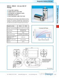
MD16 /MD19 - 34 mm OD CF<br />
Flange<br />
<br />
<br />
<br />
<br />
<br />
True <strong>UHV</strong> rotation<br />
High torque to size ratio<br />
No bellows or dynamic seals<br />
Bakeable to 250°C<br />
Zero-backlash under low load<br />
The MD16 is the ‘work horse’ of the MagiDrive series.<br />
The standard drive provides suffi cient torque for the<br />
majority of miniature feedthrough requirements.<br />
The MD19 variant maintains the same dimensions as<br />
the MD16 but provides increased levels of torque.<br />
MagiDrive body MD16 MD19<br />
System mounting fl ange CF16 34 mm (1.33” OD)<br />
Construction<br />
Machined from<br />
one piece 316L<br />
Shaft style Solid<br />
Break-away torque<br />
Maximum no load spin<br />
speed (standard<br />
bearings)<br />
Maximum shaft axial<br />
thrust<br />
0.45 Nm<br />
(0.33 lbf ft)<br />
1000 rpm<br />
66 N (15 lbf)<br />
Bakeout 250 ° C<br />
0.56 Nm<br />
(0.41 lbf ft)<br />
Tel:+44(0)1323 811188 sales@uhvdesign.com www.uhvdesign.com<br />
Magnetic Rotary Drives<br />
MD16TX000Z<br />
011<br />
MD16 MagiDrive Range
MD16 MagiDrive Range<br />
012<br />
Magnetic Rotary Drives<br />
MD16/ MD19 part code generator<br />
Size Actuation Gearing options Shaft Bearings<br />
MD16 T 000 Z<br />
MD19 TF 030 CE<br />
BF M<br />
P<br />
CF<br />
K<br />
KF<br />
D<br />
IS (1-4)*<br />
ISS (1-4)*<br />
ID (1-6)*<br />
RA<br />
RAI<br />
Actuation options Shaft options Bearing options<br />
Manual 000 Standard shaft Z Standard bearing<br />
T Standard thimble 030 30 mm shaft CE Ceramic bearing<br />
TF Standard with friction control M Modular shaft<br />
BF Brake with friction control<br />
P Timing pulley<br />
CF<br />
Calibrated thimble with friction<br />
control<br />
K Knurled end cap<br />
KF<br />
Knurled end cap with friction<br />
control<br />
D Dual shaft<br />
Motorised<br />
IS In-Line stepper motor<br />
ISS<br />
In-Line stepper motor with<br />
switches<br />
ID In-Line DC motor<br />
Pneumatic<br />
RA Pneumatic actuator<br />
RAI<br />
Pneumatic actuator with 2 x<br />
reed switches and visual<br />
position indicators<br />
X<br />
Special and custom variants available<br />
please contact sales.<br />
For a full explanation of the partcodes<br />
please see pages 004 - 007.<br />
* For information on gearing options for<br />
motorised MagiDrives please see page<br />
006.<br />
Example partcode: MD16TX000Z<br />
MD16 - MD16 MagiDrive<br />
T - Standard thimble<br />
X000 - Standard shaft<br />
Z - Standard bearings<br />
www.uhvdesign.com sales@uhvdesign.com Tel:+44(0)1323 811188
MD16CFX000Z<br />
MD16IDX000Z<br />
MD16ISX000Z<br />
MD16RAX000Z<br />
MD16RAIX000Z<br />
MD16PX000Z<br />
MD16TXMZ<br />
Tel:+44(0)1323 811188 sales@uhvdesign.com www.uhvdesign.com<br />
Magnetic Rotary Drives<br />
MD16DX000Z<br />
013<br />
MD16 MagiDrive Range
MD20 MagiDrive Range<br />
014<br />
Magnetic Rotary Drives<br />
MD20 / MD21 - 70 mm OD CF<br />
Flange<br />
<br />
<br />
<br />
<br />
<br />
True <strong>UHV</strong> rotation<br />
High torque to size ratio<br />
No bellows or dynamic seals<br />
Bakeable to 250°C<br />
Zero-backlash under low load<br />
The MD20 MagiDrive provides suffi cient torque for<br />
the majority of miniature feedthrough applications<br />
requiring a CF38 (70 mm / 2-3/4” OD) fl ange. The<br />
MD21 variant maintains the same dimensions as<br />
the MD20 but provides increased levels of torque.<br />
MagiDrive body MD20 MD21<br />
System mounting fl ange CF38 70 mm (2.75” OD)<br />
Rear fl ange None<br />
Construction<br />
Machined from one piece<br />
316L<br />
Shaft style Solid<br />
Break-away torque<br />
Maximum no load spin<br />
speed (standard<br />
bearings)<br />
Maximum shaft axial<br />
thrust<br />
0.45 Nm<br />
(0.33 lbf ft)<br />
500 rpm<br />
66 N (15 lbf)<br />
Bakeout 250 ° C<br />
0.56 Nm<br />
(0.41 lbf ft)<br />
MD20TX000Z<br />
www.uhvdesign.com sales@uhvdesign.com Tel:+44(0)1323 811188
MD20 / MD21 part code generator<br />
Tel:+44(0)1323 811188 sales@uhvdesign.com www.uhvdesign.com<br />
Magnetic Rotary Drives<br />
Size Actuation Gearing options Shaft Bearings<br />
MD20 T 000 Z<br />
MD21 TF 030 CE<br />
BF M<br />
P<br />
CF<br />
K<br />
KF<br />
D<br />
IS (1-4)*<br />
ISS (1-4)*<br />
ID (1-6)*<br />
RA<br />
RAI<br />
Actuation options Shaft options Bearing options<br />
Manual 000 Standard shaft Z Standard bearing<br />
T Standard thimble 030 30 mm shaft CE Ceramic bearing<br />
TF Standard with friction control M Modular shaft<br />
BF Brake with friction control<br />
P Timing pulley<br />
CF<br />
Calibrated thimble with friction<br />
control<br />
K Knurled end cap<br />
KF<br />
Knurled end cap with friction<br />
control<br />
D Dual shaft<br />
Motorised<br />
IS In-Line stepper motor<br />
ISS<br />
In-Line stepper motor with<br />
switches<br />
ID In-Line DC motor<br />
Pneumatic<br />
RA Pneumatic actuator<br />
RAI<br />
Pneumatic actuator with 2 x<br />
reed switches and visual<br />
position indicators<br />
X<br />
Special and custom variants available<br />
please contact sales.<br />
For a full explanation of the partcodes<br />
please see pages 004 - 007.<br />
* For information on gearing options for<br />
motorised MagiDrives please see page<br />
006.<br />
Example partcode: MD20TX000Z<br />
MD20 - MD20 MagiDrive<br />
T - Standard thimble<br />
X000 - Standard shaft<br />
Z - Standard bearings<br />
015<br />
MD20 MagiDrive Range
MD20 MagiDrive Range<br />
016<br />
Magnetic Rotary Drives<br />
MD20CFX000Z MD20TXMZ<br />
MD20PX000Z<br />
MD20DX000Z<br />
MD20IDX000Z<br />
MD20ISX000Z<br />
MD20RAX000Z<br />
MD20RAIX000Z<br />
www.uhvdesign.com sales@uhvdesign.com Tel:+44(0)1323 811188
MD25 - 70 mm OD CF Flange<br />
<br />
<br />
<br />
<br />
<br />
<br />
True <strong>UHV</strong> rotation<br />
High torque to size ratio<br />
No bellows or dynamic seals<br />
Bakeable to 250°C<br />
Bearing options<br />
Multiple shaft options<br />
The MD25 provides a medium torque solution for<br />
various rotation applications.<br />
MagiDrive body MD25<br />
System mounting fl ange CF38 70 mm (2.75” OD)<br />
Rear fl ange None<br />
Construction<br />
Shaft style Solid<br />
Machined from one piece<br />
316L<br />
Break-away torque 2.4 Nm (1.77 lbf ft)<br />
Maximum no load spin<br />
speed (standard<br />
bearings)<br />
Maximum shaft axial<br />
thrust<br />
500 rpm<br />
Bakeout 250 ° C<br />
100 N (22.5 lbf)<br />
Tel:+44(0)1323 811188 sales@uhvdesign.com www.uhvdesign.com<br />
Magnetic Rotary Drives<br />
MD25TX000Z<br />
017<br />
MD25 MagiDrive Range
MD25 MagiDrive Range<br />
018<br />
Magnetic Rotary Drives<br />
MD25 part code generator<br />
Size Actuation Gearing options Shaft Bearings<br />
MD25 X<br />
T 000 Z<br />
D M CE<br />
P<br />
CB<br />
IS (1-4)*<br />
ISS (1-4)*<br />
SS (1-4)*<br />
SSS (1-4)*<br />
ID (1-4)*<br />
SD (1-4)*<br />
RA<br />
RAI<br />
Actuation options Shaft options Bearing options<br />
Manual 000 Standard shaft Z Standard bearing<br />
T Standard thimble M Modular shaft CE Ceramic bearing<br />
D Dual shaft<br />
P Timing pulley<br />
CB<br />
Motorised<br />
Calibrated thimble with<br />
thumbscrew brake<br />
IS In-Line stepper motor<br />
ISS<br />
In-Line stepper motor with<br />
switches<br />
SS Side mounted stepper motor<br />
SSS<br />
Side mounted stepper motor<br />
with switches<br />
ID In-Line DC motor<br />
SD Side mounted DC motor<br />
Pneumatic<br />
RA Pneumatic actuator<br />
RAI<br />
Pneumatic actuator with 2 x<br />
reed switches and visual<br />
position indicators<br />
Special and custom variants available<br />
please contact sales.<br />
For a full explanation of the partcodes<br />
please see pages 004 - 007.<br />
* For information on gearing options<br />
for motorised MagiDrives please see<br />
page 006.<br />
Example partcode: MD25TX000Z<br />
MD25 - MD25 MagiDrive<br />
T - Standard thimble<br />
X000 - Standard shaft<br />
Z - Standard bearings<br />
www.uhvdesign.com sales@uhvdesign.com Tel:+44(0)1323 811188
MD25CBX000Z<br />
MD25PX000Z<br />
MD25IDX000Z<br />
MD25ISX000Z<br />
MD25RAX000Z<br />
MD25RAIX000Z<br />
MD25DX000Z<br />
Tel:+44(0)1323 811188 sales@uhvdesign.com www.uhvdesign.com<br />
Magnetic Rotary Drives<br />
MD25SDX000Z<br />
MD25SSX000Z<br />
019<br />
MD25 MagiDrive Range
MD35 MagiDrive Range<br />
020<br />
Magnetic Rotary Drives<br />
MD35 - 70 mm OD CF Flange<br />
<br />
<br />
<br />
<br />
<br />
True <strong>UHV</strong> rotation<br />
High torque<br />
No bellows or dynamic seals<br />
Bakeable to 250°C<br />
Zero-backlash under low load<br />
The MD35 MagiDrive provides the highest torque,<br />
within the range, on a 70 mm OD (2-3/4” OD CF)<br />
fl ange. The drive is ideally suited to applications<br />
such as the rotation of samples and small platens,<br />
where stability is key. The MD35 is also available in<br />
a hollow confi guration (see page 030).<br />
MagiDrive body MD35<br />
System mounting fl ange<br />
Rear fl ange None<br />
Construction<br />
CF38 70 mm (2.75”<br />
OD)<br />
Machined from one<br />
piece 316L<br />
Shaft style Spigot fl ange<br />
Break-away torque 4.5 Nm (3.32 lbf ft)<br />
Maximum no load spin speed<br />
(standard bearings)<br />
500 rpm<br />
Maximum shaft axial thrust 200 N (45 lbf)<br />
Bakeout 250 ° C<br />
MD35TX000Z<br />
www.uhvdesign.com sales@uhvdesign.com Tel:+44(0)1323 811188
MD35 part code generator<br />
Tel:+44(0)1323 811188 sales@uhvdesign.com www.uhvdesign.com<br />
Magnetic Rotary Drives<br />
Size Actuation Gearing options Shaft Bearings<br />
MD35 X 000<br />
T Z<br />
B CE<br />
CB SE<br />
P<br />
D<br />
IS (1-4)*<br />
ISS (1-4)*<br />
SS (1-4)*<br />
SSS (1-4)*<br />
ID (1-4)*<br />
SD (1-4)*<br />
RA<br />
RAI<br />
Actuation options Shaft options Bearing options<br />
Manual 000 Spigot fl ange Z Standard bearing<br />
T Standard thimble CE Ceramic bearing<br />
B Standard with friction control SE Semiconductor bearing<br />
CB Calibrated thimble with thumbscrew brake<br />
P Timing pulley<br />
D Dual shaft<br />
Motorised<br />
IS In-Line stepper motor<br />
ISS In-Line stepper motor with switches<br />
SS Side mounted stepper motor<br />
SSS Side mounted stepper motor with switches<br />
ID In-Line DC motor<br />
SD Side mounted DC motor<br />
Pneumatic<br />
RA Pneumatic actuator<br />
RAI<br />
Pneumatic actuator with 2 x reed switches<br />
and visual position indicator<br />
Special and custom variants available please<br />
contact sales.<br />
For a full explanation of the partcodes please<br />
see pages 004 - 007.<br />
* For information on gearing options for<br />
motorised MagiDrives please see page 006.<br />
Example partcode: MD35TX000Z<br />
MD35 - MD35 MagiDrive<br />
T - Standard thimble<br />
X000 - Standard shaft<br />
Z - Standard bearings<br />
021<br />
MD35 MagiDrive Range
MD35 MagiDrive Range<br />
022<br />
Magnetic Rotary Drives<br />
MD35CBX000Z<br />
MD35PX000Z<br />
MD35IDX000Z<br />
MD35ISX000Z<br />
MD35RAX000Z<br />
MD35RAIX000Z<br />
MD35DX000Z<br />
MD35SDX000Z<br />
MD35SSX000Z<br />
www.uhvdesign.com sales@uhvdesign.com Tel:+44(0)1323 811188
MD64 - 114 mm OD CF Flange<br />
<br />
<br />
<br />
<br />
<br />
True <strong>UHV</strong> rotation<br />
High torque<br />
No bellows or dynamic seals<br />
Bakeable to 250°C<br />
Zero-backlash under low load<br />
The MD64 MagiDrive provides high power rotation<br />
through a high stiffness coupling. This drive would<br />
be ideally suited to robot type or platen rotation<br />
applications. The MD64 drive is also available in a<br />
hollow confi guration (see page 033).<br />
MagiDrive body MD64<br />
System mounting fl ange<br />
Rear fl ange None<br />
Construction<br />
CF64 114 mm (4.5”<br />
OD)<br />
Machined from one<br />
piece 316L<br />
Shaft style Spigot fl ange<br />
Break-away torque 10 Nm (7.38 lbf ft)<br />
Maximum no load spin speed<br />
(standard bearings)<br />
500 rpm<br />
Maximum shaft axial thrust 400 N (90 lbf)<br />
Bakeout 250 ° C<br />
Tel:+44(0)1323 811188 sales@uhvdesign.com www.uhvdesign.com<br />
Magnetic Rotary Drives<br />
MD64TX000Z<br />
023<br />
MD64 MagiDrive Range
MD64 MagiDrive Range<br />
024<br />
Magnetic Rotary Drives<br />
MD64 part code generator<br />
Size Actuation Gearing options Shaft Bearings<br />
MD64 X 000<br />
T Z<br />
BF SE<br />
CB<br />
P<br />
IS* (1-4)*<br />
ISS* (1-4)*<br />
SS* (1-4)*<br />
SSS* (1-4)*<br />
ID* (1-4)*<br />
SD* (1-4)*<br />
RA<br />
RAI<br />
Actuation options Shaft options Bearing options<br />
Manual 000 Spigot fl ange Z Standard bearing<br />
T Standard thimble SE Semiconductor bearing<br />
BF Brake with friction control<br />
CB Calibrated thimble with brake<br />
P Timing pulley<br />
Motorised<br />
IS In-line stepper motor<br />
ISS<br />
In-line stepper motor with<br />
switches<br />
SS Side mounted stepper motor<br />
SSS<br />
Side mounted stepper motor<br />
with switches<br />
ID In-Line DC motor<br />
SD Side mounted DC motor<br />
Pneumatic<br />
RA Pneumatic actuator<br />
RAI<br />
Pneumatic actuator with 2 x<br />
reed switches and visual<br />
position indicators<br />
Special and custom variants available<br />
please contact sales.<br />
For a full explanation of the partcodes<br />
please see pages 004 - 007.<br />
* For information on gearing options for<br />
motorised MagiDrives please see page<br />
006.<br />
Example partcode: MD64TX000Z<br />
MD64 - MD64 MagiDrive<br />
T - Standard thimble<br />
X000 - Standard shaft<br />
Z - Standard bearings<br />
www.uhvdesign.com sales@uhvdesign.com Tel:+44(0)1323 811188
Tel:+44(0)1323 811188 sales@uhvdesign.com www.uhvdesign.com<br />
Magnetic Rotary Drives<br />
MD64CBX000Z MD64DX000Z<br />
MD64PX000Z<br />
MD64SDX000Z<br />
MD64SSX000Z<br />
MD64IDX000Z<br />
MD64ISX000Z<br />
MD64RAX000Z<br />
MD64RAIX000Z<br />
025<br />
MD64 MagiDrive Range
MD100 MagiDrive Range<br />
026<br />
Magnetic Rotary Drives<br />
MD100 - 152.4 mm OD CF Flange<br />
<br />
<br />
<br />
<br />
<br />
<br />
Largest rotary drive in range<br />
Stiff, high torque coupling<br />
True <strong>UHV</strong> rotation<br />
No bellows or dynamic seals<br />
Zero-backlash under low loads<br />
Bakeable to 250°C<br />
The MD100 is ideally suited to demanding<br />
applications requiring very high torque and stiffness<br />
characteristics, such as indexing robots or rotating<br />
large loads. The MD100 is also available in a hollow<br />
confi guration (see page 036).<br />
MagiDrive body MD100<br />
System mounting fl ange CF100 152 mm (6” OD)<br />
Rear fl ange None<br />
Clear bore 65 mm<br />
Construction Fabrication<br />
Shaft style Spigot fl ange<br />
Break-away torque 25 Nm (18.45 lbf ft)<br />
Maximum no load spin<br />
speed (standard bearings)<br />
200 rpm<br />
Max’ shaft axial thrust 400 N (90 lbf)<br />
Bakeout 250 ° C<br />
MD100TX000Z<br />
www.uhvdesign.com sales@uhvdesign.com Tel:+44(0)1323 811188
MD100 part code generator<br />
Tel:+44(0)1323 811188 sales@uhvdesign.com www.uhvdesign.com<br />
Magnetic Rotary Drives<br />
Size Actuation Shaft Bearings<br />
MD100 X 000 Z<br />
T<br />
P<br />
SS*<br />
SSS*<br />
SD<br />
Special and custom variants available please contact sales.<br />
For a full explanation of the partcodes please see pages 004 - 007.<br />
* For information on gearing options for motorised MD100 MagiDrives please contact sales.<br />
Actuation options Shaft options Bearing options<br />
Manual 000 Spigot fl ange Z Standard bearing<br />
T Standard thimble<br />
P Timing pulley<br />
Motorised<br />
SS Side mounted stepper motor<br />
SSS<br />
Example partcode: MD100TX000Z<br />
MD100 - MD100 MagiDrive<br />
T - Standard thimble<br />
X000 - Standard shaft<br />
Z - Standard bearings<br />
Side mounted stepper motor<br />
with switches<br />
SD Side mounted DC motor<br />
For further drawing information please contact <strong>UHV</strong> <strong>Design</strong>.<br />
027<br />
MD100 MagiDrive Range
Hollow MagiDrive Range<br />
028<br />
Magnetic Rotary Drives<br />
Hollow MagiDrive Range<br />
The four largest MagiDrives are available in a ‘hollow’<br />
confi guration, terminating with a CF fl ange at the<br />
rear. This allows services to be passed through the<br />
drive or alternatively, an additional MagiDrive to be<br />
mounted to the rear, providing a secondary axes of<br />
rotation. Up to four independent axes of rotation<br />
can be provided by combining the MD16, MD35H,<br />
MD64H and MD100H MagiDrives.<br />
This ‘stacking’ capability is typically used to provide<br />
simple solutions to sophisticated manipulation<br />
requirements.<br />
A typical example is the EpiCentre 282 right angled<br />
manipulator, which heats a silicon wafer to 1000°C<br />
whilst rotating it on the primary and azimuthal axes<br />
(a photograph of which is included at the bottom<br />
of this page). The use of hollow MagiDrives greatly<br />
simplifi es the design preventing the need for special<br />
head positioning gears.<br />
Details of the ‘hollow’ range are included in the<br />
following pages.<br />
www.uhvdesign.com sales@uhvdesign.com Tel:+44(0)1323 811188
Schematic of stacked ‘hollow’<br />
range illustrating three concentric<br />
rotations<br />
Tel:+44(0)1323 811188 sales@uhvdesign.com www.uhvdesign.com<br />
Magnetic Rotary Drives<br />
029<br />
Hollow MagiDrive Range
MD35H MagiDrive Range<br />
030<br />
Magnetic Rotary Drives<br />
MD35H - 70 mm OD CF Flange<br />
<br />
<br />
<br />
<br />
<br />
<br />
Hollow drive<br />
12 mm clear bore<br />
Medium torque<br />
No bellows or dynamic seals<br />
Bakeable to 250°C<br />
Zero-backlash under low load<br />
The MD35H is a medium torque, medium stiffness<br />
rotary drive. Confi gured with a hollow body<br />
the MD35H has a rear fi xed CF16 fl ange enabling a<br />
component to pass through the centre, such as <strong>UHV</strong><br />
<strong>Design</strong>’s cold lance, or a second MagiDrive rotary<br />
feedthrough.<br />
MagiDrive body MD35H<br />
System mounting fl ange<br />
Rear fl ange<br />
Construction<br />
CF38 70 mm<br />
(2.75” OD)<br />
CF16 34 mm<br />
(1.33” OD)<br />
Machined from one<br />
piece 316L<br />
Shaft style Spigot fl ange<br />
Break-away torque 4.5 Nm (3.32 lbf ft)<br />
Maximum no load spin speed<br />
(standard bearings)<br />
500 rpm<br />
Maximum shaft axial thrust 200 N (45 lbf)<br />
Bakeout 250 ° C<br />
MD35HTX000Z<br />
www.uhvdesign.com sales@uhvdesign.com Tel:+44(0)1323 811188
MD35H part code generator<br />
Tel:+44(0)1323 811188 sales@uhvdesign.com www.uhvdesign.com<br />
Magnetic Rotary Drives<br />
Size Actuation Gearing options Shaft Bearings<br />
MD35H X 000<br />
T Z<br />
CB CE<br />
P SE<br />
SS (1-4)*<br />
SSS (1-4)*<br />
SD (1-4)*<br />
SRA<br />
SRAI<br />
Actuation options Shaft options Bearing options<br />
Manual 000 Spigot fl ange Z Standard bearing<br />
T Standard thimble CE Ceramic bearing<br />
CB Brake with friction control SE Semiconductor bearing<br />
P Timing pulley<br />
Motorised<br />
SS Side mounted stepper motor<br />
SSS<br />
Side mounted stepper motor<br />
with switches<br />
SD Side mounted DC motor<br />
Pneumatic<br />
SRA<br />
SRAI<br />
Example partcode: MD35HTX000Z<br />
MD35H - MD35H MagiDrive<br />
T - Standard thimble<br />
X000 - Standard shaft<br />
Z - Standard bearings<br />
Side mounted Pneumatic<br />
actuator<br />
Side mounted Pneumatic<br />
actuator with 2 x reed switches<br />
and visual position indicators<br />
Special and custom variants available please contact sales.<br />
For a full explanation of the partcodes please see pages 004 - 007.<br />
* For information on gearing options for motorised MagiDrives<br />
please see page 006.<br />
031<br />
MD35H MagiDrive Range
MD35H MagiDrive Range<br />
032<br />
Magnetic Rotary Drives<br />
MD35HCBX000Z MD35HPX000Z<br />
MD35HRAX000Z<br />
MD35HRAIX000Z<br />
MD35HSDX000Z<br />
MD35HSSX000Z<br />
www.uhvdesign.com sales@uhvdesign.com Tel:+44(0)1323 811188
MD64H - 114 mm OD CF Flange<br />
<br />
<br />
<br />
<br />
<br />
<br />
Hollow drive<br />
High torque /stability<br />
26 mm clear bore<br />
No bellows or dynamic seals<br />
Bakeable to 250°C<br />
Zero-backlash under low load<br />
The MD64H MagiDrive provides high power rotation<br />
through a high stiffness coupling. This drive is ideally<br />
suited to platen rotation or robot type applications.<br />
The MD64H has a rear rotatable fl ange enabling a<br />
component to pass through the centre such as <strong>UHV</strong><br />
<strong>Design</strong>’s cold lance, or a second MagiDrive rotary<br />
feedthrough.<br />
MagiDrive body MD64H<br />
System mounting fl ange<br />
Rear fl ange<br />
Construction<br />
CF64 114 mm<br />
(4.5” OD)<br />
CF38 70 mm<br />
(2.75” OD)<br />
Machined from one<br />
piece 316L<br />
Shaft style Spigot fl ange<br />
Break-away torque 10 Nm (7.38 lbf ft)<br />
Maximum no load spin speed<br />
(standard bearings)<br />
500 rpm<br />
Maximum shaft axial thrust 400 N (90 lbf)<br />
Bakeout 250 ° C<br />
Tel:+44(0)1323 811188 sales@uhvdesign.com www.uhvdesign.com<br />
Magnetic Rotary Drives<br />
MD64HTX000Z<br />
033<br />
MD64H MagiDrive Range
MD64H MagiDrive Range<br />
034<br />
Magnetic Rotary Drives<br />
MD64H part code generator<br />
Size Actuation Gearing options Shaft Bearings<br />
MD64H X 000<br />
T Z<br />
P SE<br />
SS (1-4)*<br />
SSS (1-4)*<br />
SD (1-4)*<br />
SRA<br />
SRAI<br />
Actuation options Shaft options Bearing options<br />
Manual 000 Standard shaft Z Standard bearing<br />
T Standard thimble SE Semiconductor bearing<br />
P Timing pulley<br />
Motorised<br />
SS Side mounted stepper motor<br />
SSS<br />
Side mounted stepper motor<br />
with switches<br />
SD Side mounted DC motor<br />
Pneumatic<br />
SRA<br />
SRAI<br />
Example partcode: MD64HTX000Z<br />
MD64H - MD64H MagiDrive<br />
T - Standard thimble<br />
X000 - Standard shaft<br />
Z - Standard bearings<br />
Pneumatic actuator with<br />
switches<br />
Pneumatic actuator with 2 x<br />
reed switches, visual position<br />
indicators and switches<br />
Special and custom variants available please contact sales.<br />
For a full explanation of the partcodes please see pages 004 - 007.<br />
* For information on gearing options for motorised MagiDrives<br />
please see page 006.<br />
www.uhvdesign.com sales@uhvdesign.com Tel:+44(0)1323 811188
MD64HRAX000Z<br />
MD64HRAIX000Z<br />
MD64HPX000Z<br />
Tel:+44(0)1323 811188 sales@uhvdesign.com www.uhvdesign.com<br />
Magnetic Rotary Drives<br />
MD64HSDX000Z<br />
MD64HSSX000Z<br />
035<br />
MD64H MagiDrive Range
MD100H MagiDrive Range<br />
036<br />
Magnetic Rotary Drives<br />
MD100H - 152.4 mm OD CF Flange<br />
<br />
<br />
<br />
<br />
<br />
<br />
Hollow drive<br />
65 mm clear bore<br />
Powerful, stiff coupling<br />
No bellows or dynamic seals<br />
Bakeable to 250°C<br />
Zero-backlash under low loads<br />
The MD100H is selected for demanding high torque<br />
and stiffness applications, such as indexing robots<br />
or rotating large loads. The MD100H has the largest<br />
clear bore in the range and a rear rotatable fl ange.<br />
This enables a component to pass through the<br />
centre such as <strong>UHV</strong> <strong>Design</strong>’s cold lance, or a second<br />
MagiDrive rotary feedthrough.<br />
MagiDrive body MD100H<br />
System mounting fl ange CF100 152 mm (6” OD)<br />
Rear fl ange CF64 114 mm (4.5” OD)<br />
Clear bore 65 mm<br />
Construction Fabrication<br />
Shaft style Spigot fl ange<br />
Break-away torque 25 Nm (18.45 lbf ft)<br />
Maximum no load spin<br />
speed (standard bearings)<br />
200 rpm<br />
Max’ shaft axial thrust 400 N (90 lbf)<br />
Bakeout 250 ° C<br />
MD100HTX000Z<br />
www.uhvdesign.com sales@uhvdesign.com Tel:+44(0)1323 811188
MD100H part code generator<br />
Tel:+44(0)1323 811188 sales@uhvdesign.com www.uhvdesign.com<br />
Magnetic Rotary Drives<br />
Size Actuation Shaft Bearings<br />
MD100H X 000 Z<br />
T<br />
P<br />
SS*<br />
SSS*<br />
SD*<br />
Actuation options Shaft options Bearing options<br />
Manual 000 Spigot fl ange Z Standard bearing<br />
T Standard thimble<br />
P Timing pulley<br />
Motorised<br />
SS Side mounted stepper motor<br />
SSS<br />
Example partcode: MD100HTX000Z<br />
MD100H - MD100H MagiDrive<br />
T - Standard thimble<br />
X000 - Standard shaft<br />
Z - Standard bearings<br />
Side mounted stepper motor<br />
with switches<br />
SD Side mounted DC motor<br />
For dimensional and drawing information please contact <strong>UHV</strong> <strong>Design</strong><br />
Special and custom variants available please contact sales.<br />
For a full explanation of the partcodes please see pages 004 - 007.<br />
* For information on gearing options for motorised MD100H<br />
MagiDrives please contact sales.<br />
037<br />
MD100H MagiDrive Range
Customised Drives<br />
038<br />
Magnetic Rotary Drives<br />
Customised MagiDrives<br />
MD16 MagiDrive with viewing window<br />
MD16 MagiDrives with 3 position locking facility<br />
MD16 MagiDrive with Rotary Source Shutter<br />
MD20 MagiDrives with extended<br />
bearing housing<br />
MD16 MagiDrive with rear switch<br />
www.uhvdesign.com sales@uhvdesign.com Tel:+44(0)1323 811188
Shutters<br />
2<br />
Shutters<br />
Rotary Source Shutters 040<br />
Viewport Shutters 043<br />
Linear Shutters 046<br />
sales@uhvdesign.com www.uhvdesign.com 039<br />
Shutters
Rotary Source Shutters<br />
040<br />
Shutters<br />
Rotary Source Shutters<br />
Pneumatic actuation<br />
Adjustable sweep (30 °-170 °)<br />
<br />
<br />
<br />
Specifi cation Table<br />
MagiDrive Mounting fl ange Sweep Break-away torque<br />
MD10 CF10 * (1” OD CF)<br />
30 ° -170 °<br />
Adjustable actuation speed<br />
Position feedback switches<br />
Visual position indicator<br />
<strong>UHV</strong> <strong>Design</strong>’s high quality rotary source shutters are<br />
becoming an industry standard for fl ux switching<br />
solutions. The pneumatic actuation provides a<br />
simple low cost solution for shutter applications such<br />
as sputter sources, ion guns or viewport shutters.<br />
Range<br />
Based on the MagiDrive rotary feedthroughs (see<br />
section one), the range includes six different sizes,<br />
to match the torque requirements for an array of<br />
applications. Technical assistance with size selection<br />
is available on request. Each drive is fi tted with an<br />
external pneumatic actuator, providing adjustable<br />
sweep between 30-170 o . Flow control valves are<br />
also supplied to adjust the speed of actuation. Use<br />
of the MagiDrive range ensures ultimate vacuum<br />
integrity through the single piece ‘vacuum envelope’<br />
design.<br />
Actuation details<br />
A solenoid operated spool valve switches compressed<br />
gas between the actuator ports. Energising the<br />
solenoid will sweep the shutter through the<br />
required angle; de-energising the solenoid returns<br />
the shutter to its start position. Actuators can also<br />
be fi tted with ‘Auto Switch’ assemblies, complete<br />
with reed switches for system feedback and visual<br />
position indicators.<br />
Shaft and shutter blades<br />
Source shutters are supplied with standard Magidrive<br />
shaft options (see page 042 for drawings).<br />
Customised shafts and shutter blades can also be<br />
quoted upon request. Extended bearing housings<br />
can be provided for longer shafts. Please contact<br />
sales for further information.<br />
Torsional<br />
stiffness<br />
0.18 Nm (0.13 lbf ft) See Page 008<br />
MD16 CF16 (1.33” OD CF) 0.45 Nm (0.33 lbf ft) See Page 011<br />
MD20<br />
0.45 Nm (0.33 lbf ft) See Page 014<br />
MD25 CF38 (2.75” OD CF)<br />
(adjustable)<br />
1.0 Nm (7.38 lbf ft) See Page 017<br />
MD35 2.5 Nm (1.84 lbf ft) See Page 020<br />
MD64 CF64 (4.5” OD CF) 10 Nm (7.38 lbf ft) See Page 023<br />
Maximum air<br />
input pressure<br />
6.8 bar<br />
(98 PSI)<br />
Flow control<br />
port size<br />
4 mm OD<br />
pipe<br />
* For more information on the CF10 MicroFlange please see page 151<br />
www.uhvdesign.com sales@uhvdesign.com Tel:+44(0)1323 811188
Rotary Source Shutter part code generator<br />
Size Shutter type Shaft Bearings<br />
MD10 RA 000<br />
MD16 RAI M<br />
MD20<br />
MD25<br />
MD35<br />
MD64<br />
Customer Name:<br />
Postal address:<br />
Tel: Fax: Email:<br />
Flange to shutter distance (L)<br />
Shutter width (W)<br />
Offset (O)<br />
Shutter material, typically 316 stainless steel, Molybdenum,<br />
or Tantalum<br />
and fi nally it would be useful for us to know the shutter<br />
speed so we can size the MagiDrive accordingly for torque<br />
Tel:+44(0)1323 811188 sales@uhvdesign.com www.uhvdesign.com<br />
X Z<br />
Shutter type Shaft Bearing options<br />
RA Pneumatically actuated 000<br />
RAI<br />
Pneumatically actuated with<br />
two reed switches and visual<br />
position indicators<br />
Special and custom variants<br />
available please contact<br />
sales. For a full explanation<br />
of the partcodes please see<br />
pages 004 - 007.<br />
Shaft and shutter blades<br />
Due to the diverse requirements for shutter<br />
designs, <strong>UHV</strong> <strong>Design</strong> do not offer a standard<br />
shutter; rather we customize a basic ‘teardrop’<br />
concept shown in the adjacent fi gure<br />
to the users specifi c requirement.<br />
To this end please supply the information<br />
indicated in the table below, photocopy<br />
and fax to <strong>UHV</strong> <strong>Design</strong> on +44 (0)1323<br />
811999.<br />
Extended bearing housings can be provided<br />
for longer shafts. Please contact sales for<br />
further information.<br />
Standard stub shaft or spigot<br />
fl ange<br />
M Modular shaft<br />
Z Standard bearing<br />
Shutters<br />
Example partcode: MD10RAX000Z<br />
MD10 - MD10 Rotary Source Shutter<br />
RA - Pneumatically actuated<br />
X000 - Standard shaft<br />
Z - Standard bearings<br />
041<br />
Rotary Source Shutters
Rotary Source Shutters<br />
042<br />
Shutters<br />
MD10RAX000Z<br />
MD10RAIX000Z<br />
MD16RAX000Z<br />
MD16RAIX000Z<br />
MD20RAX000Z<br />
MD20RAIX000Z<br />
MD35RAX000Z<br />
MD35RAIX000Z<br />
MD25RAX000Z<br />
MD25RAIX000Z<br />
MD64RAX000Z<br />
For MD64 shaft detail please see page 025<br />
www.uhvdesign.com sales@uhvdesign.com Tel:+44(0)1323 811188
Viewport Shutters<br />
<br />
<br />
<br />
<br />
Manual or pneumatic actuation<br />
Position switch option<br />
Fully bakeable to 250°C<br />
Friction control system<br />
Introduction to Viewport Shutters<br />
<strong>UHV</strong> <strong>Design</strong> offers a range of viewport shutters<br />
to protect system windows during process, such<br />
as vacuum deposition. Utilising the magneticallycoupled<br />
MagiDrive rotary feedthroughs (section 1)<br />
for the shutter actuation, the range can be actuated<br />
manually or pneumatically, where remote control is<br />
required. The MagiDrive’s low stray magnetic fi eld<br />
ensures compatibility with RHEED measurements.<br />
The range also includes the unique ‘AutoClose’<br />
series, preventing accidental coating of the viewing<br />
window. Viewport shutters are available on four<br />
fl ange sizes from CF38 to CF150 (2-3/4” to 8”<br />
OD).<br />
Manual Actuation<br />
Manually actuated viewport shutters are fi tted with<br />
an external friction control system, ensuring the<br />
blade remains in the desired position without the<br />
need for position locks.<br />
Manual ‘AutoClose’ shutters<br />
The unique ‘AutoClose’ shutter safeguards viewport<br />
windows from accidental deposition. It allows endusers<br />
to manually open the shutter for viewing,<br />
but upon release, automatically closes, protecting<br />
the window from accidental coating, for example.<br />
‘AutoClose’ motion is driven by an inherent position<br />
bias, with intrinsic deceleration. The ‘AutoClose’<br />
prevents the costly and time-consuming requirement<br />
to break vacuum in order to replace/clean windows<br />
accidentally coated. This is particularly undesirable<br />
for <strong>UHV</strong> systems. ‘AutoClose’ shutters can be<br />
mounted in any orientation and are bakeable to<br />
250 o C.<br />
Pneumatic actuation<br />
Viewport shutters can also be fi tted with a<br />
pneumatically actuated MagiDrive. Used in their<br />
simplest form, they could be operated remotely from<br />
a control panel or switch. For more sophisticated<br />
protection the pneumatically actuated MagiDrive<br />
could be interlocked to the ‘vacuum process’, such<br />
that activating a deposition source, for example,<br />
would automatically close the viewport shutter.<br />
Furthermore, for critical applications, an optional<br />
‘feedback-switch’ assembly can be fi tted to the<br />
drive to confi rm to the process controller that the<br />
shutter is in the closed position. Specifi c features<br />
of the pneumatically actuated MagiDrives can be<br />
found on page 040.<br />
Tel:+44(0)1323 811188 sales@uhvdesign.com www.uhvdesign.com<br />
Shutters<br />
Miniature actuator<br />
Viewport shutters are fi tted with the MD16 MagiDrive<br />
(page 011) as standard. The two smaller shutters<br />
can also be confi gured with the miniature MD10<br />
MicroDrive (page 008) for applications where space<br />
is a primary constraint.<br />
Selection tables and drawings can be found<br />
overleaf.<br />
043<br />
Viewport Shutters
Viewport Shutters<br />
044<br />
Shutters<br />
Viewport Shutter part code generator<br />
Standard actuator<br />
Viewport shutter Flange size Actuation (optional)<br />
VPS<br />
Miniature actuator<br />
38 AC<br />
64 RA<br />
100 RAI<br />
150<br />
Viewport shutter Flange size Actuation (optional)<br />
VPSM<br />
Flange size Actuation<br />
38 CF38 70 mm (2.75”) OD None Manual rotary drive with friction control<br />
64 CF64 114 mm (4.5”) OD AC AutoClose manually actuated self-closing shutter<br />
100 CF100 152 mm (6”) OD RA Pneumatically actuated<br />
150 CF150 203 mm (8”) OD RAI<br />
38 RA<br />
64 RAI<br />
Example partcode: VPS38<br />
VPS - Viewport Shutter<br />
38 - CF38 OD<br />
Special and custom variants available please contact sales.<br />
Pneumatically actuated with two Reed switches for<br />
position feedback and visual position indicators<br />
www.uhvdesign.com sales@uhvdesign.com Tel:+44(0)1323 811188
Standard actuator<br />
Actuation Code Flange size<br />
Manual<br />
Pneumatic<br />
Miniature actuator<br />
Tel:+44(0)1323 811188 sales@uhvdesign.com www.uhvdesign.com<br />
Dimension (mm)<br />
Shutters<br />
A B C D<br />
VPS38/ VPS38AC CF38 (2.75” OD) 37.0 32.8 10.0 116.0<br />
VPS64/ VPS64AC CF64 (4.5” OD) 63.5 57.0 19.5 135.0<br />
VPS100 / VPS100AC CF100 (6” OD) 101.6 87.0 35.5 158.0<br />
VPS150/ VPS150AC CF150 (8” OD) 152.4 133.2 52.5 173.0<br />
VPS38RA/ VPS38RAI CF38 (2.75” OD) 37.0 31.8 10.0 179.5<br />
VPS64RA/ VPS64RAI CF64 (4.5” OD) 63.5 56.9 19.5 198.5<br />
VPS100RA/ VPS100RAI CF100 (6” OD) 101.6 87.0 35.5 221.5<br />
VPS150RA / VPS150RAI CF150 (8” OD) 152.4 133.2 52.5 236.5<br />
Actuation Code Flange size<br />
Manual<br />
Pneumatic<br />
Dimension (mm)<br />
A B C D<br />
VPSM38 CF38 (2.75” OD) 37 32.8 10 106.5<br />
VPSM64 CF64 (4.5” OD) 63.5 57 19.5 125<br />
VPSM38RA/ VPS38RAI CF38 (2.75” OD) 37 32.8 10 157.5<br />
VPSM64RA/ VPS64RAI CF38 (2.75” OD) 63.5 57 19.5 176<br />
045<br />
Viewport Shutters
Linear Shutters<br />
046<br />
Shutters<br />
Linear Shutters for <strong>UHV</strong><br />
Deposition<br />
<br />
<br />
<br />
<br />
<br />
Ideal for MBE and sputtering<br />
applications<br />
Fully bakeable to 250°C<br />
Based on MagiDrive technology<br />
Choice of blade size and material<br />
Dedicated shutter control unit<br />
available<br />
Introduction to Linear Shutters<br />
<strong>UHV</strong> <strong>Design</strong> manufacture a range of linear stroke<br />
shutters for fl ux switching various deposition<br />
sources. Originally designed for the demanding<br />
requirements of Molecular Beam Epitaxy, the low<br />
particulate generation of the shutter makes it<br />
ideal for production applications like sputtering.<br />
All products in this range are fully bakeable and<br />
constructed from materials compatible with ultra<br />
high vacuum.<br />
Rocking Beam Shutter<br />
<strong>UHV</strong> <strong>Design</strong>’s Rocking Beam Shutter relies on our<br />
MagiDrive range to pass motion into the vacuum<br />
envelope, eliminating the need for bellows. This<br />
elegant, simple and reliable pneumatically actuated<br />
component utilises a camshaft to reduce end of<br />
travel shock in high speed applications.<br />
The design ensures that only the rotating pivot<br />
bearings are inside the vacuum enclosure.<br />
All Linear Shutters have the option of molybdenum,<br />
tantalum, PBN or stainless steel shutter blades to<br />
suit customer requirements.<br />
For detailed specifi cations and customer drawings<br />
for this range of products please contact sales.<br />
www.uhvdesign.com sales@uhvdesign.com Tel:+44(0)1323 811188
Push Pull Devices<br />
3<br />
Introduction to Push Pull Devices 048<br />
MPPRL - Rotary and Linear Motion 049<br />
MPPL - Linear Guided Motion 051<br />
MPP - Linear Non-guided Motion 053<br />
Push Pull Devices<br />
sales@uhvdesign.com www.uhvdesign.com 047<br />
Push Pull Devices
Push Pull Devices<br />
048<br />
Push Pull Devices<br />
Push Pull Devices<br />
<br />
<br />
<br />
<br />
<br />
Linear and linear + rotary motion<br />
High power-to-size ratio<br />
No bellows - no vacuum thrust<br />
Manual, motorised or pneumatic<br />
actuation<br />
Bakeable to 250°C<br />
Introduction to the Magnetic Push/Pull range<br />
The Magnetic Push/Pull range provides linear and<br />
linear plus rotary motion solutions with up to<br />
250 mm (10”) stroke. This compact range is<br />
specifi cally designed for low load applications, such<br />
as specimen transfer, thermocouple ‘contacting’<br />
or manual shutters, for high or ultra high vacuum<br />
applications.<br />
Production proven coupling technology<br />
The Magnetic Push/Pull series benefi ts from a<br />
high power-to-size ratio, inherited from coupling<br />
technology pioneered by <strong>UHV</strong> <strong>Design</strong> for the<br />
‘PowerProbe’ sample transfer arms. The result is a<br />
rigid linear coupling with over 90 N (20 lbf) linear<br />
thrust and torque in excess of 0.4 Nm (0.29 lbf ft).<br />
Please see diagrams on this page.<br />
Utilising <strong>UHV</strong> <strong>Design</strong>’s magnetic coupling technology<br />
removes the need for edge-welded bellows,<br />
incorporated within traditional ‘push/pull’ designs.<br />
Their elimination maximises vacuum integrity,<br />
providing a robust, cost effective solution. Also,<br />
unlike a bellows-sealed device, the Magnetic Push/<br />
Pull is not subject to the thrust due to vacuum,<br />
resulting in smooth, free-moving operation.<br />
The range consists of three series with varying<br />
actuation options such as manual, pneumatic and<br />
stepper or DC motorised.<br />
The Magnetic Push/Pull range provides a simple and<br />
intrinsically safe alternative to bellows push/pull<br />
systems.<br />
www.uhvdesign.com sales@uhvdesign.com Tel:+44(0)1323 811188
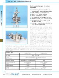
MPPRL Series -<br />
Rotary and Linear Motion<br />
<br />
<br />
<br />
<br />
<br />
High power-to-size ratio<br />
No bellows, no vacuum thrust<br />
Manual actuation<br />
Position lock facility<br />
Bakeable to 250°C<br />
The MPPRL provides linear and continuous rotary<br />
motion of the vacuum shaft. The range provides a<br />
simple and intrinsically safe alternative to bellows<br />
push/pull systems. Linear strokes between 50 mm<br />
and 250 mm are offered as standard, with special<br />
strokes available upon request.<br />
Utilising <strong>UHV</strong> <strong>Design</strong>’s magnetic coupling technology,<br />
the Magnetic Push/Pull removes the need for<br />
edge-welded bellows ‘stacks’, incorporated within<br />
traditional ‘push/pull’ designs. Their elimination<br />
maximises vacuum integrity, providing a robust,<br />
cost effective solution. Also, unlike a bellows-sealed<br />
device, the MPPRL is not subject to the thrust<br />
due to vacuum, resulting in smooth free-moving<br />
operation.<br />
Push Pull<br />
Model<br />
MPPRL-50<br />
MPPRL-100<br />
MPPRL-150<br />
MPPRL-250<br />
Tel:+44(0)1323 811188 sales@uhvdesign.com www.uhvdesign.com<br />
Push Pull Devices<br />
Flange Stroke ‘A’ Rotation<br />
34 mm OD<br />
(1.33” OD CF)<br />
34 mm OD<br />
(1.33” OD CF)<br />
34 mm OD<br />
(1.33” OD CF)<br />
34 mm OD<br />
(1.33” OD CF)<br />
50 mm<br />
(2” travel) continuous<br />
100 mm<br />
(4” travel) continuous<br />
150 mm<br />
(6” travel) continuous<br />
250 mm<br />
(10”<br />
travel)<br />
continuous<br />
049<br />
Rotary and Linear Motion
Rotary and Linear Motion<br />
050<br />
Push Pull Devices<br />
MPPRL Series - Rotary and Linear motion part code generator<br />
If you have a special requirement that is not offered in the standard partcode structure please contact sales.<br />
Series Stroke Actuation<br />
MPPRL - -<br />
50 H<br />
100<br />
150<br />
250<br />
Special and custom variants available please contact sales.<br />
Stroke Actuation<br />
50 50 mm (2” travel) H Manual thimble<br />
100 100 mm (4” travel)<br />
150 150 mm (6” travel)<br />
250 250 mm (10” travel)<br />
Example partcode: MPPRL-50-H<br />
MPPRL - Rotary and Linear Push Pull<br />
50 - 50 mm travel<br />
H - Manual thimble<br />
www.uhvdesign.com sales@uhvdesign.com Tel:+44(0)1323 811188
MPPL Series -<br />
Linear Guided Motion<br />
<br />
<br />
<br />
<br />
<br />
High power-to-size ratio<br />
No bellows, no vacuum thrust<br />
Position lock facility<br />
Robust design<br />
Manual, motorised and pneumatic<br />
actuation<br />
Based on the larger Linear PowerProbe series<br />
(page 58), the MPPL provides internally guided<br />
linear motion of the vacuum shaft, guaranteeing<br />
rotation-free motion. Furthermore, the high axial<br />
thrust coupling produces no torque and so external<br />
rotation of the thimble does not apply a rotational<br />
force internally, ensuring smooth motion.<br />
The range can be actuated manually, pneumatically<br />
or motorised with DC or stepper motors. Additionally,<br />
switches can be provided to prevent over-travel and<br />
to aid system interlocks.<br />
The MPPL provides a simple and intrinsically safe<br />
alternative to bellows push/pull systems. Utilising<br />
<strong>UHV</strong> <strong>Design</strong>’s magnetic coupling technology the<br />
Magnetic Push/Pull removes the need for edgewelded<br />
bellows ‘stacks’, incorporated within<br />
traditional ‘push/pull’ designs. Their elimination<br />
maximises vacuum integrity, providing a robust,<br />
cost effective solution. Also, unlike a bellowssealed<br />
device, the MPPL is not subject to the thrust<br />
due to vacuum, resulting in smooth, free-moving<br />
operation.<br />
Push Pull<br />
Model<br />
MPPL-50<br />
MPPL-100<br />
MPPL-150<br />
MPPL-250<br />
Tel:+44(0)1323 811188 sales@uhvdesign.com www.uhvdesign.com<br />
Push Pull Devices<br />
Flange Stroke ‘A’ Bakeout<br />
34 mm OD<br />
(1.33” OD CF)<br />
34 mm OD<br />
(1.33” OD CF)<br />
34 mm OD<br />
(1.33” OD CF)<br />
34 mm OD<br />
(1.33” OD CF)<br />
50 mm<br />
(2” travel)<br />
100 mm<br />
(4” travel)<br />
150 mm<br />
(6” travel)<br />
250 mm<br />
(10” travel)<br />
250°C<br />
250°C<br />
250°C<br />
250°C<br />
051<br />
Linear Guided Motion
Linear Guided Motion<br />
052<br />
Push Pull Devices<br />
MPPL Series - Linear guided motion part code generator<br />
If you have a special requirement that is not offered in the standard partcode structure please contact sales.<br />
Size Stroke Actuation<br />
MPPL - -<br />
Special and custom variants available please contact sales.<br />
Stroke Actuation<br />
50 H<br />
100 P<br />
150 ID<br />
250 IS<br />
50 50 mm (2” travel) H Manual thimble<br />
100 100 mm (4” travel) P Pneumatic<br />
Example partcode: MPPL-50-H<br />
MPPL - Linear Push Pull<br />
50 - 50 mm travel<br />
H - Manual thimble<br />
150 150 mm (6” travel) ID In-line DC motor<br />
250 250 mm (10” travel) IS In-line Stepper motor<br />
www.uhvdesign.com sales@uhvdesign.com Tel:+44(0)1323 811188
MPP Series -<br />
Linear Non-guided Motion<br />
<br />
<br />
<br />
<br />
<br />
High power-to-size ratio<br />
No bellows, no vacuum thrust<br />
Position lock facility<br />
Robust design<br />
Manual, motorised and pneumatic<br />
actuation options<br />
MPPs provide linear motion of an ‘unguided’ vacuum<br />
shaft (free to rotate). This is used to manipulate<br />
slides or pivot arms where a guided system may<br />
confl ict with the mechanism. Please note that<br />
although the vacuum shaft is free to rotate the MPP<br />
does not provide rotation.<br />
The range can be actuated manually, pneumatically<br />
or motorised with DC or stepper motors. Additionally,<br />
switches can be provided to prevent over-travel and<br />
to aid system interlocks.<br />
The MPP range provides a simple and intrinsically<br />
safe alternative to bellows push/pull systems.<br />
Utilising <strong>UHV</strong> <strong>Design</strong>’s magnetic coupling technology<br />
the Magnetic Push/Pull removes the need for<br />
edge-welded bellows ‘stacks’, incorporated within<br />
traditional ‘push/pull’ designs. Their elimination<br />
maximises vacuum integrity, providing a robust,<br />
cost effective solution. Also, unlike a bellowssealed<br />
device, the MPP is not subject to the thrust<br />
due to vacuum, resulting in smooth, free-moving<br />
operation.<br />
Push Pull<br />
Model<br />
MPP-50<br />
MPP-100<br />
MPP-150<br />
MPP-250<br />
Tel:+44(0)1323 811188 sales@uhvdesign.com www.uhvdesign.com<br />
Push Pull Devices<br />
Flange Stroke ‘A’ Bakeout<br />
34 mm OD<br />
(1.33” OD CF)<br />
34 mm OD<br />
(1.33” OD CF)<br />
34 mm OD<br />
(1.33” OD CF)<br />
34 mm OD<br />
(1.33” OD CF)<br />
50 mm<br />
(2” travel)<br />
100 mm<br />
(4” travel)<br />
150 mm<br />
(6” travel)<br />
250 mm<br />
(10” travel)<br />
250°C<br />
250°C<br />
250°C<br />
250°C<br />
053<br />
Linear Non-Guided Motion
Linear Non-Guided Motion<br />
054<br />
Push Pull Devices<br />
MPP Series - Linear non-guided motion part code generator<br />
If you have a special requirement that is not offered in the standard partcode structure please contact sales.<br />
Series Stroke Actuation<br />
MPP - -<br />
Special and custom variants available please contact sales.<br />
Stroke Actuation<br />
50 H<br />
100 P<br />
150 ID<br />
250 IS<br />
50 50 mm (2” travel) H Manual thimble<br />
100 100 mm (4” travel) P Pneumatic<br />
150 150 mm (6” travel) ID In-line DC motor<br />
Example partcode: MPP-50-H<br />
MPP - Non-guided Linear Push Pull<br />
50 - 50 mm travel<br />
H - Manual thimble<br />
250 250 mm (10” travel) IS In-line Stepper motor<br />
www.uhvdesign.com sales@uhvdesign.com Tel:+44(0)1323 811188
Section n 4<br />
Sample Transfer Tools<br />
Introduction to Professional Transfer Tool Range 056<br />
Torque, Thrust and Defl ection Graphs 056<br />
Sample Transfer Tool Selection Criteria 057<br />
Linear PowerProbe 058<br />
Linear/Rotary PowerProbe 061<br />
Axis Selectable PowerProbe 064<br />
Elevating PowerProbe 066<br />
Dual Axis PowerProbe 068<br />
Port Aligners 071<br />
PowerProbe Hand-off System 072<br />
Wobble Sticks 074<br />
Pincer / Gripper Wobble Sticks 076<br />
Sample Transfer Tools<br />
sales@uhvdesign.com www.uhvdesign.com 055<br />
Sample Transfer Tools
Sample Transfer Tools<br />
056<br />
Sample Transfer Tools<br />
Figure 1<br />
Figure 2<br />
Figure 3<br />
Reference conversion data: 1 Nm = 0.738 lbf ft<br />
Note: PowerProbes with a stroke of more<br />
than 609 mm employ hollow shafts to reduce<br />
weight and are therefore slightly less stiff.<br />
Professional Transfer Tools<br />
<br />
<br />
<br />
<br />
<br />
Linear or linear/rotary motion<br />
Fully bakeable to 250 o C<br />
High power coupling<br />
Zero backlash under low load<br />
Unrivalled performance<br />
Introduction to the PowerProbe range<br />
Building on the success of the MagiDrive as<br />
the premier magnetically coupled <strong>UHV</strong> rotary<br />
feedthrough, <strong>UHV</strong> <strong>Design</strong> developed a second<br />
magnetic coupling specifi cally for linear motion. This<br />
coupling forms the basis of the Professional Transfer<br />
Tool range, providing linear or combined linear and<br />
rotary motion within ultra high vacuum. These<br />
unique probes avoid the limitations of conventional<br />
designs, offering up to an order of magnitude<br />
improvements in key aspects of performance.<br />
Performance power<br />
Professional Transfer Tools have unrivalled<br />
transmission performance. The standard linear<br />
coupling has a break-away force of 180 N (40<br />
lbf), in comparison to the 26-50 N of our nearest<br />
competitors. A high power option is also available,<br />
with a staggering 310 N (69 lbf).<br />
Figure 1 illustrates the axial stiffness of the coupling<br />
under load, demonstrating that the standard probe<br />
defl ects by less than 1 mm for a 98 N (22 lbf) load.<br />
In terms of rotation, the rotary transmission is<br />
essentially based upon the MD35 MagiDrive (see<br />
page 020) delivering 4 Nm (3 lbf ft) break-away<br />
torque. This is four times the level offered by our<br />
nearest competitor. The unique rotary coupling<br />
retains the renowned angular rigidity of the<br />
MagiDrive series (see Figure 2).<br />
Figure 3 shows the vertical defl ection at the end of<br />
a horizontally mounted PowerProbe transfer arm as<br />
a function of extended length, and with an applied<br />
weight/load of 10 N. The relationship between load<br />
and defl ection is approximately linear for typical<br />
transfer loads.<br />
The crucial aspect of these performance<br />
characteristics is not necessarily the load carrying<br />
capacity, but the stiffness of the coupling. The<br />
probes are, therefore, ideal for sample transfer<br />
applications.<br />
The Professional Transfer Tools are fully bakeable to<br />
250°C and do not require dismantling. The probes<br />
are suitable for use between atmospheric pressure<br />
and ultra high vacuum.<br />
www.uhvdesign.com sales@uhvdesign.com Tel:+44(0)1323 811188
Selecting your Sample Transfer Tool<br />
The Range<br />
There are several sample transfer solutions in the range offering a variety of solutions.<br />
Tel:+44(0)1323 811188 sales@uhvdesign.com www.uhvdesign.com<br />
Sample Transfer Tools<br />
Item and Code Description Page<br />
Linear PowerProbe (LPP) Linear motion only 058<br />
Linear/rotary PowerProbe (PP) Linear and rotary motion 061<br />
Axis selectable PowerProbe (ASP) Independent linear, rotary, or combined linear and rotary<br />
motion<br />
Elevating PowerProbe (EPP) Linear motion with 12 mm of vertical lift of the end<br />
effector to facilitate sample transfer<br />
Dual Axis PowerProbe (DAP) Linear motion of the main shaft and rotary motion of a<br />
second internal through shaft<br />
A range of port aligners is offered (page 071) to allow fi nal alignment of the sample transfer arm with internal<br />
system components. Additionally, each of the above can be mounted on a ‘Y Shift’, which lifts and lowers the<br />
entire sample transfer tool providing a complete sample transfer system (page 072).<br />
Actuation Options<br />
Code Item Description<br />
H Manual actuation Manual actuation provides the most basic method for motion<br />
adjustment. Simple movement of the guide thimble actuates both<br />
linear and linear/rotary motion in one action.<br />
HR Manual with bakeable<br />
limit switches<br />
This option includes a bakeable proximity reed switch for the retracted<br />
position to aid system interlocks.<br />
E Extension handle Extension handles enable users to operate the transfer tool from a<br />
distance whilst maintaining full control of the actuation. This would prove<br />
useful for applications where the user has to observe an experiment<br />
in-vacuum whilst moving the transfer tool. This is particularly useful<br />
for long travel variants.<br />
SS Stepper motor driven Linear PowerProbes can be stepper motor driven. They are supplied<br />
with bakeable limit switches at each end of travel along with a ‘home’<br />
switch to act as a datum point. The Linear PowerProbe is provided<br />
within an overall enclosure to shield moving components.<br />
SD DC motor driven DC motorised Linear PowerProbes are supplied with limit switches (no<br />
home switch) and an overall enclosure to shield moving parts.<br />
Manual PowerProbe (H) Stepper motor driven linear PowerProbe (SS)<br />
064<br />
066<br />
068<br />
057<br />
Sample Transfer Tools
Linear PowerProbe<br />
058<br />
Sample Transfer Tools<br />
Linear PowerProbe (LPP Series)<br />
<br />
<br />
<br />
<br />
<br />
<br />
<br />
Linear motion only<br />
No external guidance required<br />
10 x the thrust of conventional probes<br />
Fully bakeable to 250 o C<br />
Motorisation options<br />
Position switch options<br />
Adjustable stop collar<br />
The Linear PowerProbe should be selected where<br />
only linear motion is required and twisting or turning<br />
of the sample would be undesirable.<br />
An anti-rotation system is fi tted internally ensuring<br />
straight, in-line motion, despite any rotation of the<br />
external drive carriage. This removes the need for<br />
the unwieldy external linear guide bars used by<br />
other manufacturers.<br />
The manual LPP can be fi tted with a bakeable limit<br />
switch for the retracted position to aid system<br />
interlocks. The motorised confi guration is fi tted<br />
with similar switches for both the extended and<br />
retracted positions.<br />
Extension handle<br />
The extension handle option allows the user to<br />
operate the device from a distance whilst maintaining<br />
full control of the actuation. This would prove useful<br />
for applications where the user has to observe an<br />
experiment in-vacuum whilst applying linear motion<br />
and is particularly useful for long travel variants.<br />
Linear Power Probe Low Power Standard High Power<br />
Mounting fl ange size CF38 70 mm (2.75”) OD<br />
Linear axial coupling breakaway force 70 N (15.75 lbf) 180 N (40.5 lbf) 310 N (69.75 lbf)<br />
Sample weight / load capacity<br />
Maximum recommended internally applied load<br />
when vertically installed<br />
Maximum recommended internal load carrying capacity will<br />
be a function of probe extension, but we recommend not to<br />
exceed a moment of 50 Nm.<br />
See Figure 3 on page 056 for defl ection versus load.<br />
Not suitable for<br />
vertical mounting<br />
This is a function of the load acceleration.<br />
In a static case the load may approach<br />
the coupling break-away force,<br />
however, it would be wise to apply a<br />
sensible safety factor.<br />
Pressure range Atmosphere to 5x10 -11 mbar<br />
Bakeout temperature<br />
Fully bakeable to 250 o C without the removal of any<br />
components (except for motors)<br />
Position locking Thumbscrew<br />
www.uhvdesign.com sales@uhvdesign.com Tel:+44(0)1323 811188
Linear PowerProbe range part code generator<br />
Tel:+44(0)1323 811188 sales@uhvdesign.com www.uhvdesign.com<br />
Sample Transfer Tools<br />
Series Flange size Linear Stroke Actuation method<br />
35 - -<br />
LPPL 250 H<br />
LPP 304 HR<br />
LPPH 457 E<br />
Series Linear stroke Actuation method<br />
LPPL<br />
LPP<br />
LPPH<br />
Example partcode: LPP35-250-H<br />
LPP - Linear PowerProbe<br />
35 - CF38 70 mm OD<br />
250 - 250 mm travel<br />
H - Manual thimble<br />
Low Power Linear<br />
PowerProbe<br />
Linear<br />
PowerProbe<br />
High Power Linear<br />
PowerProbe<br />
250 mm (10”) H Manual<br />
609 SD<br />
914 SS<br />
1219<br />
304 mm (12”) HR Manual with bakeable limit switch for retracted position<br />
457 mm (18”) E Extension handle<br />
609 mm (24”) SD<br />
914 mm (36”) SS<br />
1219 mm (48”)<br />
Stroke 250mm 304mm 457mm 609mm 914mm 1219mm<br />
‘A’ Dimension 396 450 668.4 821 1225 1529.6<br />
Side mounted 24V DC motor with bakeable limit switches at<br />
extended and retracted positions<br />
Side mounted stepper motor with bakeable home and limit<br />
switches at extended and retracted positions<br />
Manual actuation<br />
059<br />
Linear PowerProbe
Linear PowerProbe<br />
060<br />
Sample Transfer Tools<br />
Motorised actuation<br />
www.uhvdesign.com sales@uhvdesign.com Tel:+44(0)1323 811188
PowerProbe (PP Series)<br />
<br />
<br />
<br />
<br />
<br />
<br />
<br />
Linear and rotary motion<br />
10 x the thrust, 4 x torque of<br />
conventional probes<br />
Fully bakeable to 250 o C<br />
Retracted switch options<br />
Position lock facility<br />
Zero-backlash under low load<br />
Adjustable stop collar<br />
The PowerProbe provides both linear and rotary<br />
motion of the sample, via a single actuator.<br />
The PowerProbe’s powerful magnetic coupling<br />
technology combined with its innovative guidance<br />
system provides performance far in advance of<br />
conventional probes on the market.<br />
The high torque characteristics are achieved by<br />
utilising MagiDrive rotary coupling technology.<br />
this combined with a high thrust linear coupling<br />
ensures optimum drive performance on both axes.<br />
Therefore, actuation of the external drive carriage<br />
in either axis will result in the precise translation of<br />
this motion to the sample.<br />
The Power Probe can be fi tted with a bakeable limit<br />
switch for the retracted position, aiding system<br />
interlocks.<br />
Tel:+44(0)1323 811188 sales@uhvdesign.com www.uhvdesign.com<br />
Sample Transfer Tools<br />
PowerProbe Low Power Standard High Power<br />
Mounting fl ange size<br />
CF38 70 mm (2.75”) OD<br />
CF64 114 mm (4.5”) OD for ‘long travel’ variant<br />
Linear coupling breakaway force 70 N (15.75 lbf) 180 N (40.5 lbf) 310 N (69.75 lbf)<br />
Rotary coupling breakaway torque 4 Nm (2.95 lbf ft)<br />
Sample weight / load capacity<br />
Maximum recommended internally applied load<br />
when vertically installed<br />
Bakeout temperature<br />
Maximum recommended internal load carrying capacity will<br />
be a function of probe extension, but we recommend not to<br />
exceed a moment of 50 Nm.<br />
See Figure 3 on page 056 for defl ection versus load.<br />
Not suitable for<br />
vertical mounting<br />
This is a function of the load<br />
acceleration. In a static case the load<br />
may approach the coupling break-away<br />
force, however, it would be wise to<br />
apply a sensible safety factor.<br />
PowerProbes are bakeable to 250 o C without the removal of<br />
any components.<br />
Position locking Thumbscrew<br />
061<br />
PowerProbe
PowerProbe<br />
062<br />
Sample Transfer Tools<br />
PowerProbe range part code generator<br />
Series Flange Size Linear Stroke Actuation method<br />
- -<br />
PPL 35 304 H<br />
PP 64* 457 HR<br />
PPH 609<br />
Example partcode: PP35-304-H<br />
PP - PowerProbe<br />
35 - CF38 70 mm OD<br />
304 - 304 mm travel<br />
H - Manual thimble<br />
914<br />
1219<br />
1524*<br />
*1524 mm (60”) stroke ‘Long PowerProbes’ are mounted on CF64 114 mm (4.5”) OD fl anges<br />
Series Linear Stroke Actuation method<br />
PPL Low power PowerProbe 304 mm (12”) H Manual<br />
PP PowerProbe 457 mm (18”) HR Manual with bakeable limit switch retracted position<br />
PPH High power PowerProbe 609 mm (24”)<br />
914 mm (36”)<br />
1219 mm (48”)<br />
1524 mm (60”)<br />
Stroke 304mm 457mm 609mm 914mm 1219mm<br />
‘A’ Dimension 515 668.4 821 1225 1529.6<br />
www.uhvdesign.com sales@uhvdesign.com Tel:+44(0)1323 811188
Tel:+44(0)1323 811188 sales@uhvdesign.com www.uhvdesign.com<br />
Sample Transfer Tools<br />
063<br />
PowerProbe
Axis Selectable PowerProbe<br />
064<br />
Sample Transfer Tools<br />
Axis Selectable PowerProbe<br />
(ASPP Series)<br />
<br />
<br />
<br />
<br />
<br />
Linear, rotary, linear & rotary motion<br />
Maximum user fl exibility<br />
10 x the thrust, 4 x torque of<br />
conventional probes<br />
Fully bakeable to 250 o C<br />
Adjustable stop collar<br />
The Axis-Selectable PowerProbe provides both<br />
linear and rotary motion, but unlike the standard<br />
PowerProbe range each axis can be separately<br />
locked if required. Four separate modes of operation<br />
are therefore possible: -<br />
• Linear motion only, rotation locked<br />
• Rotation only, linear motion locked<br />
• Linear and rotary motion combined<br />
• Linear and rotary both locked<br />
The PowerProbe’s powerful magnetic coupling<br />
technology combined with its innovative guidance<br />
system provides performance far in advance of<br />
conventional probes on the market. The design also<br />
includes a general position lock to prevent motion<br />
of either axis.<br />
Axis Selectable PowerProbe Standard<br />
Mounting fl ange CF38 70 mm (2.75”) OD<br />
Linear coupling breakaway force 180 N (40 lbf)<br />
Rotary coupling breakaway torque 4 Nm (2.95 lbf ft)<br />
Sample weight / load capacity<br />
Max recommended internally applied load when<br />
vertically installed<br />
Maximum recommended internal load carrying capacity will<br />
be a function of probe extension, but we recommend not to<br />
exceed a moment of 50 Nm.<br />
See Figure 3 on page 056 for defl ection versus load.<br />
This is a function of the load acceleration. In a static case<br />
the load may approach the coupling break-away force,<br />
however, it would be wise to apply a sensible safety factor.<br />
Pressure range Atmosphere to 5x10 -11 mbar<br />
Bakeout temperature Bakeable to 250 o C without the removal of any components<br />
Position locking Thumbscrew<br />
Rotary position index locking Spring loaded pin<br />
www.uhvdesign.com sales@uhvdesign.com Tel:+44(0)1323 811188
Axis Selected PowerProbe range part code generator<br />
Tel:+44(0)1323 811188 sales@uhvdesign.com www.uhvdesign.com<br />
Sample Transfer Tools<br />
Series Size Stroke Actuation method<br />
ASPP - - H<br />
Example partcode: ASPP35-304-H<br />
ASPP - Axis Selectable PowerProbe<br />
35 - CF38 70 mm OD<br />
304 - 304 mm travel<br />
H - Manual thimble<br />
35 - 304<br />
If you have a special requirement that is not offered in the standard partcode structure please contact<br />
sales.<br />
457<br />
609<br />
914<br />
Series Stroke Actuation method<br />
ASPP Axis Selectable PowerProbe 304 mm (12”) H Manual<br />
457 mm (18”)<br />
609 mm (24”)<br />
914 mm (36”)<br />
Stroke 304mm 457mm 609mm 914mm<br />
‘A’ Dimension 558 711 862 1168<br />
065<br />
Axis Selectable PowerProbe
Elevating PowerProbe<br />
066<br />
Sample Transfer Tools<br />
Elevating PowerProbe<br />
(EPP Series)<br />
<br />
<br />
<br />
<br />
<br />
Linear motion with ‘elevation’<br />
12 mm lift throughout stroke<br />
10 x the thrust of conventional probes<br />
Fully bakeable to 250 o C<br />
Adjustable stop collar<br />
Elevating PowerProbe Standard<br />
The Elevating PowerProbe transforms conventional<br />
approaches to sample transfer. In addition to its<br />
internally guided linear motion, the probe has the<br />
ability to elevate its end effector throughout its<br />
stroke, providing 12 mm of lift in the Y axis for<br />
sample hand-off.<br />
This PowerProbe variant greatly simplifi es sample<br />
transfer techniques, providing a single device to<br />
provide both linear motion for sample introduction<br />
and the lift/lower motion to collect or hand-off the<br />
sample.<br />
Essentially the Elevating PowerProbe provides a<br />
complete sample handling system in its own right<br />
removing the need for secondary motion tools.<br />
This in turn reduces cost and simplifi es the transfer<br />
process itself. For additional fl exibility, automated<br />
transfer or increased ‘Y’ motion, see page 072.<br />
Mounting fl ange CF38 70 mm (2.75”) OD<br />
Elevating (lift/lower) motion 12 mm<br />
Linear coupling breakaway force 180 N (40.5 lbf)<br />
Sample weight / load capacity<br />
Maximum recommended internal load carrying capacity will be a<br />
function of probe extension, but we recommend not to exceed a<br />
moment of 50 Nm.<br />
See Figure 3 on page 056 for defl ection versus load.<br />
Pressure range Atmosphere to 5x10 -11 mbar<br />
Bakeout temperature Bakeable to 250 o C without the removal of any components.<br />
Position locking Thumbscrew<br />
www.uhvdesign.com sales@uhvdesign.com Tel:+44(0)1323 811188
Elevating PowerProbe range part code generator<br />
Tel:+44(0)1323 811188 sales@uhvdesign.com www.uhvdesign.com<br />
Sample Transfer Tools<br />
Series Size Stroke Actuation method<br />
EPP 35 - -<br />
Example partcode: EPP35-250-H<br />
EPP - Elevating PowerProbe<br />
35 - CF38 70 mm OD<br />
250 - 250 mm travel<br />
H - Manual<br />
250 H<br />
304 HR<br />
457<br />
609<br />
914<br />
1219<br />
If you have a special requirement that is not offered in the standard partcode<br />
structure please contact sales.<br />
Series Stroke Actuation method<br />
EPP Elevating PowerProbe 250 mm 10” H Manual<br />
304 mm 12” HR<br />
457 mm 18”<br />
609 mm 24”<br />
914 mm 36”<br />
1219 mm 48”<br />
Stroke 250mm 304mm 457mm 609mm 914mm 1219mm<br />
‘A’ Dimension 461 515 668.4 821 1225 1529.6<br />
Manual with bakeable limit switch for retracted<br />
position.<br />
067<br />
Elevating PowerProbe
Dual Axis PowerProbe<br />
068<br />
Sample Transfer Tools<br />
Dual Axis PowerProbe Standard<br />
Mounting fl ange CF38 70 mm (2.75”) OD<br />
Linear coupling breakaway force 180 N (40.5 lbf)<br />
Rotary coupling breakaway torque (second shaft) 4 Nm (2.95 lbf ft)<br />
Sample weight / load capacity<br />
Max recommended internally applied load when<br />
vertically installed<br />
Dual Axis PowerProbe (DAP Series)<br />
Linear primary motion<br />
Secondary internal rotating shaft<br />
10 x the thrust, 4 x torque of<br />
conventional probes<br />
Fully bakeable to 250 o C<br />
Retracted switch options<br />
Adjustable stop collar<br />
Maximum recommended internal load carrying capacity will<br />
be a function of probe extension, but we recommend not to<br />
exceed a moment of 50 Nm.<br />
See Figure 3 on page 056 for defl ection versus load.<br />
This is a function of the load acceleration. In a static case<br />
the load may approach the coupling break-away force,<br />
however, it would be wise to apply a sensible safety factor.<br />
Pressure range Atmosphere to 5x10 -11 mbar<br />
Bakeout temperature Bakeable to 250 o C without the removal of any components<br />
Position locking Thumbscrew<br />
<br />
<br />
<br />
<br />
<br />
<br />
The Dual Axis PowerProbe (DAP) has two concentric<br />
output shafts providing independent axes of<br />
motion. The outer tubular shaft has linear only<br />
motion provided by the linear PowerProbe magnetic<br />
coupling. The inner shaft has independent rotary<br />
motion provided by the PowerProbe rotary magnetic<br />
coupling. The DAP has a single driving thimble<br />
allowing concurrent actuation of both the linear and<br />
rotary axes.<br />
This PowerProbe variant is ideally suited to system<br />
designers who wish to employ a secondary motion<br />
to actuate an end effector mechanism, such as a<br />
sample locking system, for example.<br />
The Dual Axis PowerProbe benefi ts from our<br />
powerful magnetic coupling technology providing<br />
robust, reliable performance. Additionally the<br />
internal linear guidance system, prevents rotation<br />
of the main shaft, thus removing the need for<br />
conventional external guide bars, providing an<br />
elegant and compact solution to sample transfer.<br />
www.uhvdesign.com sales@uhvdesign.com Tel:+44(0)1323 811188
Dual Axis PowerProbe range part code generator<br />
Tel:+44(0)1323 811188 sales@uhvdesign.com www.uhvdesign.com<br />
Sample Transfer Tools<br />
Series Flange Size Linear Stroke Actuation method<br />
DAP 35 - -<br />
Example partcode: DAP35-250-H<br />
DAP - Dual Axis PowerProbe<br />
35 - CF38 70 mm OD<br />
250 - 250 mm travel<br />
H - Manual<br />
250 H<br />
304 HR<br />
457<br />
609<br />
914<br />
1219<br />
Series Linear Stroke Actuation method<br />
DAP Dual Axis PowerProbe 250 mm (10”) H Manual<br />
Dimensional drawing overleaf<br />
304 mm (12”) HR<br />
457 mm (18”)<br />
609 mm (24”)<br />
914 mm (36”)<br />
1219 mm (48”)<br />
Manual with bakeable limit switch for retracted<br />
position<br />
069<br />
Dual Axis PowerProbe
Dual Axis PowerProbe<br />
070<br />
Sample Transfer Tools<br />
Stroke 250mm 304mm 457mm 609mm 914mm 1219mm<br />
‘A’ Dimension 461 515 668.4 821 1225 1529.6<br />
www.uhvdesign.com sales@uhvdesign.com Tel:+44(0)1323 811188
Port Aligners<br />
<br />
<br />
<br />
<br />
Ideal for sample transfer tool<br />
alignment<br />
Linear and tilt adjustment<br />
Rigid construction<br />
Compact design<br />
Introduction to Port Aligners<br />
When combined with a sample transfer tool, a<br />
port aligner provides the ability to align the tool’s<br />
position in relation to other system components.<br />
Typically this would include alignment with a sample<br />
manipulator or sample carousel, whereby the angle<br />
of approach is critical to successful transfer. Port<br />
aligners are also useful for overcoming any port<br />
errors or general misalignment.<br />
Tel:+44(0)1323 811188 sales@uhvdesign.com www.uhvdesign.com<br />
Sample Transfer Tools<br />
The port aligner range is fully compatible with <strong>UHV</strong> <strong>Design</strong>’s sample transfer tool range (see pages 058-070).<br />
For further information on the full port aligner range see page 099.<br />
Port Aligner part code generator<br />
Series Flange Size Machined Holes<br />
PA -<br />
Flange size Bolt holes<br />
35 H<br />
64 T<br />
Example partcode: PA35-T PA - Port Aligner, 35 - CF38 70 mm OD, T - Tapped Holes<br />
35 CF38 (2.75” OD CF) H Clear bolt holes<br />
64 CF64 (4.5” OD CF) T M8 Tapped bolt holes<br />
071<br />
Port Aligners
Sample Hand-Off System<br />
072<br />
Sample Transfer Tools<br />
Hand-off System part codes<br />
Series Y Shift Actuation PowerProbe<br />
Code<br />
64-38<br />
64-64<br />
100-38<br />
100-64<br />
LDM - -<br />
Travelling<br />
fl ange<br />
CF38 70 mm<br />
(2.75” ) OD<br />
CF64 114 mm<br />
(4.5”) OD<br />
CF38 70 mm<br />
(2.75” ) OD<br />
CF64 114 mm<br />
(4.5”) OD<br />
Y Shift Type<br />
64 - 38 H<br />
64 - 64 SS<br />
100 - 38 SD<br />
100 - 64<br />
System mounting fl ange<br />
Y motion<br />
(lift/lower)<br />
State <strong>UHV</strong> <strong>Design</strong><br />
sample transfer tool<br />
part number you<br />
wish to use *<br />
Actuation Type<br />
CF64 114 mm (4.5”) OD<br />
H Manual<br />
+/- 7.5 mm<br />
CF64 114 mm (4.5”) OD SS<br />
Side mounted stepper<br />
motor<br />
CF100 152 mm (6”) OD<br />
CF100 152 mm (6”) OD<br />
Sample Hand-off System<br />
(Y-shift / PowerProbe)<br />
<br />
<br />
<br />
<br />
Combined sample introduction and<br />
hand-off capability<br />
Compatible with <strong>UHV</strong> <strong>Design</strong>’s<br />
Sample Transfer Tools<br />
Production proven design<br />
Robust construction<br />
Introduction to the sample hand-off system<br />
<strong>UHV</strong> <strong>Design</strong> have developed a standard system for<br />
sample and wafer handling which has been used<br />
for many years in production applications. The<br />
system combines the linear/ rotary motion of the<br />
Sample Transfer Tool range (pages 058-070) with<br />
the ability to lift and lower the sample to enable<br />
hand-off (transfer).<br />
This latter motion is produced by the Y-shift range of manipulators (full details on page 105), which provides<br />
+/- 7.5 mm or +/- 31 mm of ‘Y’ motion. A typical application would be the loading of wafers from a load-lock<br />
into a process chamber, and then lowering the wafer onto a manipulator for processing, as shown overleaf.<br />
Customised transfer forks are available on request.<br />
The Y shift design includes two parallel fl anges. One remains fi xed, whilst the other provides the movement.<br />
A high quality, supple, edge-welded bellows spans the fl anges to accommodate the required motion while<br />
ensuring an all-metal vacuum enclosure. The device works by adjusting the position of the travelling fl ange,<br />
and therefore the probe and sample in relation to the fi xed system-mounting fl ange. Positioning of the<br />
travelling fl ange is controlled through an external leadscrew which can be driven either manually or motorised.<br />
A kinematically designed mechanism ensures smooth and precise motion.<br />
Example partcode:<br />
LDM64-38-H-PP35-250-H<br />
LDM - Y Shift,<br />
64/38 - CF38 travelling fl ange, CF64<br />
mounting fl ange,<br />
H - Manual actuation, fi tted with a:<br />
PP35-250-H - PowerProbe.<br />
+/- 31 mm<br />
SD Side mounted DC motor<br />
* See pages 58 and 61 for details of compatible PowerProbes<br />
www.uhvdesign.com sales@uhvdesign.com Tel:+44(0)1323 811188
Tel:+44(0)1323 811188 sales@uhvdesign.com www.uhvdesign.com<br />
Sample Transfer Tools<br />
073<br />
Sample Hand-Off System
Wobble Sticks<br />
074<br />
Sample Transfer Tools<br />
Specifi cation /<br />
Part Number<br />
Linear travel<br />
Linear break-away<br />
force<br />
WSL- series<br />
150 mm or<br />
250 mm<br />
WSLR- series<br />
95 N (21.38 lbf)<br />
Rotation NA Continuous<br />
Angular break-away<br />
torque<br />
NA<br />
Tilt +/- 15 o<br />
Suggested maximum<br />
sample mass<br />
Maximum bakeout<br />
temperature<br />
260 g<br />
250 o C<br />
0.45 Nm<br />
(0.33 lbf ft)<br />
Wobble Sticks<br />
<br />
<br />
<br />
<br />
3 or 4 axes of movement<br />
Magnetically coupled design<br />
Robust construction<br />
Modular concept<br />
The Wobble Stick is one of the simplest manipulation<br />
tools available, translating hand movements, with<br />
defi ned freedom, through a vacuum enclosure.<br />
The Wobble Stick series is based upon <strong>UHV</strong> <strong>Design</strong>’s<br />
larger PowerProbe technology (see pages 56-70),<br />
which provides high power linear and rotary motion<br />
through a magnetic coupling. The Wobble Stick<br />
range includes two series: -<br />
• WSL series, for linear motion with tilt<br />
• WSLR series, for linear/rotary motion with tilt<br />
<strong>Design</strong> concept<br />
The <strong>UHV</strong> <strong>Design</strong> Wobble Stick is a modular concept.<br />
The basic ‘WSL’ version provides lateral/tilt<br />
movement through a robust hydroformed bellows<br />
adaptor and linear push/pull motion through a<br />
magnetic coupling. In addition, the ‘WSLR’ series<br />
also provides continuous rotation, totalling fouraxes<br />
of movement.<br />
Magnetic coupling<br />
The Wobble Sticks benefi t from <strong>UHV</strong> <strong>Design</strong>’s high<br />
power magnetic coupling technology. The coupling<br />
eliminates the need for long egde-welded bellows<br />
‘stacks’, typically employed with conventional<br />
Wobble Stick designs. This reduces the risk of leaks<br />
and in doing so, improves reliability for sensitive<br />
applications. Also, unlike a bellows-sealed device,<br />
the Wobble Stick is not subject to the thrust due<br />
to vacuum, resulting in smooth, free-moving<br />
operation.<br />
Gripper and Pincer end effectors<br />
<strong>UHV</strong> <strong>Design</strong> can also offer both pincer and gripper<br />
end effectors for sample stub handling. In fact <strong>UHV</strong><br />
<strong>Design</strong> Wobble Sticks can be supplied with end<br />
effectors to suit many standard surface science<br />
applications. Please see page 076 for more details<br />
on this option.<br />
www.uhvdesign.com sales@uhvdesign.com Tel:+44(0)1323 811188
Wobble Stick range part code generator<br />
Series Linear travel (stroke) Actuation<br />
WSL 150<br />
WSLR 250<br />
- - H<br />
Series Linear travel Actuation<br />
WSL Linear and tilt motion 150 mm (6”) H Manual<br />
WSLR Linear, rotary and tilt motion 250 mm (10”)<br />
WSL Series<br />
WSLR Series<br />
Tel:+44(0)1323 811188 sales@uhvdesign.com www.uhvdesign.com<br />
Sample Transfer Tools<br />
Example partcode: WSL-150-H<br />
WSL - Linear and tilt motion<br />
150 - 150 mm travel<br />
H - Manual actuation<br />
075<br />
Wobble Sticks
Wobble Sticks<br />
076<br />
Sample Transfer Tools<br />
Specifi cation /<br />
Part Number<br />
Linear Travel<br />
WSLRG<br />
WSLRP<br />
150mm or 250mm<br />
(6” or 10”)<br />
End effector type Gripper Pincer<br />
Linear break-away force 95 N (21.38 lbf)<br />
Rotation Continuous<br />
Angular break-away torque<br />
0.45 Nm<br />
(0.33 lbf ft)<br />
Tilt +/- 15 o<br />
Suggested maximum sample<br />
mass<br />
Maximum bakeout<br />
temperature<br />
260 g<br />
250 o C<br />
Pincer Style Wobble Sticks<br />
<br />
<br />
<br />
<br />
<br />
3 or 4 axes of movement in addition<br />
to grip<br />
Gripper or Pincer shaft terminations<br />
Magnetically coupled design<br />
Robust construction<br />
Modular concept<br />
The Wobble Stick is one of the simplest manipulation<br />
tools available, translating hand movements, with<br />
defi ned freedom, through a vacuum enclosure.<br />
Gripper and Pincer end effectors<br />
<strong>UHV</strong> <strong>Design</strong> offers both pincer and gripper end<br />
effectors for sample stub handling.<br />
The gripper version is primarily designed as a<br />
retrofi t for existing ESCALAB sample stub handling<br />
systems, but has a variety of applications.<br />
The Pincer should be considered as a universal<br />
sample grip system suitable for the majority of<br />
small sample handling applications.<br />
<strong>Design</strong> concept<br />
The <strong>UHV</strong> <strong>Design</strong> Wobble Stick is a modular concept.<br />
The basic design provides lateral/tilt movement<br />
through a robust hydroformed bellows adaptor<br />
with linear push/pull motion and rotation through a<br />
powerful magnetic coupling.<br />
The fourth axis of motion, the gripper or pincer<br />
element of the Wobble Stick, is actuated through<br />
the rotary function.<br />
Magnetic coupling<br />
The Wobble Sticks benefi t from <strong>UHV</strong> <strong>Design</strong>’s high<br />
power magnetic coupling technology. The coupling<br />
eliminates the need for long edge-welded bellows<br />
‘stacks’, typically employed with conventional<br />
wobble stick designs. This reduces the risk of leaks<br />
and in doing so, improves reliability for sensitive<br />
applications. Also the Wobble Stick is not subject<br />
to thrust due to vacuum, resulting in smooth, freemoving<br />
motion.<br />
www.uhvdesign.com sales@uhvdesign.com Tel:+44(0)1323 811188
Tel:+44(0)1323 811188 sales@uhvdesign.com www.uhvdesign.com<br />
Sample Transfer Tools<br />
Wobble Stick with gripper/pincer range part code generator<br />
Series Linear travel (stroke) Actuation<br />
WSLRP 150<br />
WSLRG 250<br />
- - H<br />
Series Linear travel Actuation<br />
WSLRP Linear, rotary and tilt motion with pincer 150 mm (6”) H Manual<br />
WSLRG Linear, rotary and tilt motion with ESCA gripper 250 mm (10”)<br />
Example partcode: WSLRP-150-H<br />
WSLRP - Linear, rotary and tilt motion with pincer<br />
150 - 150 mm travel<br />
H - Manual actuation<br />
077<br />
Wobble Sticks
Wobble Sticks<br />
078<br />
Sample Transfer Tools<br />
Gripper style Wobble stick with Sample stub<br />
www.uhvdesign.com sales@uhvdesign.com Tel:+44(0)1323 811188
Section n 5<br />
Linear Motion and Alignment<br />
Selecting your Linear Shift Mechanism 080<br />
Standard Series (LSM Series) 083<br />
Long Travel Series (LSML Series) 088<br />
Compact Series (CLSM Series) 091<br />
Linear Motion with Position Alignment<br />
Tilting Series (LSMT Series) 094<br />
Lateral Offset Series (LSMX) 097<br />
Port Aligners 100<br />
Linear Motion & Alignment<br />
sales@uhvdesign.com www.uhvdesign.com 079<br />
Linear Motion & Alignment
Selecting your Linear Shift<br />
080<br />
Linear Motion & Alignment<br />
Code Linear Shift Mechanism<br />
Series<br />
Linear Shift Mechanism selection<br />
Introduction to Linear Shift Mechanisms<br />
Linear Shift Mechanisms (linear translators) provide<br />
linear motion along the port axis (Z). Typical<br />
applications include the positioning of beamline<br />
fi lters, adjustment of sputter sources and deposition<br />
stages through to production style applications.<br />
Bakeable to 250 o C, the range is supplied on CF<br />
fl anges and provides true <strong>UHV</strong> performance.<br />
The bellows sealed Linear Shift Mechanisms provide<br />
smooth, precise motion via a kinematically designed<br />
external leadscrew driven mechanism, complete<br />
with anti-rotation and anti-defl ection systems. This<br />
design ensures smooth and precise motion along<br />
the Z axis. The range has a high load capability<br />
ensured through its rigid construction.<br />
The bellows are manufactured from 316L stainless<br />
steel as standard and offer a minimum design life<br />
of 10,000 cycles. Customised units are available<br />
offering a design life of up to 1 million cycles.<br />
Product selection<br />
The Linear Shift Mechanism range is possibly the<br />
largest of its type on the market with over 500<br />
variations. To simplify selection, the range is divided<br />
into fi ve standard series to suit the majority of<br />
applications and includes strokes of up to 1 metre.<br />
It is also possible to adjust the axis of motion along<br />
the X axis and to ‘tilt’ the travelling fl ange for fi nal<br />
alignment. The following section contains detailed<br />
specifi cations, options and dimensional drawings<br />
for each. A summary of each is included below as a<br />
quick reference guide.<br />
Summary Page<br />
LSM Standard This is the most comprehensive series, offering a multitude<br />
of fl ange sizes, strokes up to 350 mm (14 “) and actuation<br />
options.<br />
LSML Long travel The Long travel series includes an upgraded structure enabling<br />
up to 1 metre (39”) of stroke.<br />
CLSM Compact The compact series has the shortest fl ange-to-fl ange-face<br />
dimension. The series is offered with a variety of fl ange sizes<br />
and strokes.<br />
LSMT With tilt for fi nal alignment The ‘tilt’ series provides the ability to tilt the travelling fl ange<br />
by +/-2 o to allow fi nal adjustment of the driven load.<br />
LSMX With ‘X’ travel for fi nal<br />
alignment<br />
This LSMX series provides the ability to adjust the lateral<br />
position of the travelling fl ange along the X axis (side-to-side)<br />
by +/- 5 mm to allow fi nal alignment of the driven load.<br />
www.uhvdesign.com sales@uhvdesign.com Tel:+44(0)1323 811188<br />
083<br />
087<br />
090<br />
093<br />
096
Linear Shift Mechanism selection<br />
Code Actuation method Description<br />
Tel:+44(0)1323 811188 sales@uhvdesign.com www.uhvdesign.com<br />
Linear Motion & Alignment<br />
Actuation<br />
Linear Shift Mechanisms can be actuated manually, pneumatically or via a DC or stepper motor.<br />
Manual Actuation<br />
Code Actuation method Description<br />
H Manual A manual handwheel provides the most basic method of actuation.<br />
GH Manual with<br />
geared-handwheel<br />
Pneumatic Actuation<br />
P Pneumatic Pneumatic actuators provide a simple solution to automated<br />
operation.<br />
Motorisation<br />
A selection of motors are available to meet the load, speed and positioning requirements of each application.<br />
All motorised linear shift mechanisms are supplied with bakeable limit switches. <strong>UHV</strong> <strong>Design</strong> offer both DC and<br />
stepper motor controllers, which are included in section 13. Motor mounting assemblies are easily removed<br />
for bakeout.<br />
Code Actuation method Description<br />
Large bore Linear Shift Mechanisms are fi tted with a geared<br />
handwheel to provide suffi cient mechanical advantage to overcome<br />
the additional thrust due to vacuum.<br />
SD DC motorised A 12 or 24V DC motor provides the motion and is mounted to the side<br />
of the LSM. Special in-line versions are available upon request.<br />
SS Stepper motor driven A stepper motor provides the motion and is mounted to the side of the<br />
LSM. Special in-line versions are available on request.<br />
UP Wiring upgrade When purchasing a Linear Shift Mechanism for use with <strong>UHV</strong> <strong>Design</strong><br />
controllers (see page 175), an additional integration upgrade is<br />
available. The upgrade includes a bakeable socket connector, mounted<br />
to the frame, to which the limit switches are pre-wired. In the case of<br />
stepper motor driven products, an extra home switch is also provided.<br />
The motor lead terminates with a connector compliant with <strong>UHV</strong><br />
<strong>Design</strong>’s controllers.<br />
081<br />
Selecting your Linear Shift
Selecting your Linear Shift<br />
082<br />
Linear Motion & Alignment<br />
Position Readout/Feedback<br />
Linear Shift Mechanisms are offered with a variety of position readout/feedback solutions.<br />
Code Item Description<br />
ES Engraved shaft Linear Shift Mechanisms can be fi tted with a scale with 1 mm<br />
increments for visual positioning.<br />
DLA Digital linear scale Digital scale displays are fi tted to Linear Shift Mechanisms via a<br />
kinematic mount ensuring precise and repeatable location, which is<br />
critical for accurate repositioning after bakeout. The scale features<br />
large, easy to read characters that can be switched between metric and<br />
imperial units. The readout has a resolution of 10 microns (0.01mm).<br />
Users can set the ‘Origin’ at any position of its stroke, from which it<br />
will provide a plus/minus scale in the units selected. The ‘Origin’ is<br />
retained in its memory until re-set by the user, even when switched<br />
off. A second temporary ‘Zero’ facility is offered to enable one-off<br />
measurements to take place, which resets to the ‘Origin’ setting when<br />
turned off.<br />
LP Linear potentiometer The Linear potentiometer option is selected where position feedback<br />
of the Linear Shift Mechanism travelling fl ange is required for closed<br />
loop control applications. The LP provides resolution and repeatability<br />
of 2 microns.<br />
The LP has a conductive resistive track and precious metal wiper that<br />
can be interfaced to a number of analogue devices such as a PLC or<br />
motor controller.<br />
The LP is attached to the LSM frame with a kinematic mount enabling<br />
it to be removed if bakeout is required.<br />
Digital Linear Scale (DLA) Linear Potentiometer (LP)<br />
www.uhvdesign.com sales@uhvdesign.com Tel:+44(0)1323 811188
LSM Linear Shift Mechanism Series<br />
<br />
<br />
<br />
<br />
<br />
Smooth kinematic motion<br />
Reliable, rigid construction<br />
Manual, motorised or pneumatic<br />
actuation<br />
Production proven design<br />
Demountable bellows assembly<br />
The LSM is the most comprehensive series in the<br />
range, offering the largest number of fl ange, stroke<br />
and actuation options. All fl anges within the series<br />
are supplied with tapped bolt holes as standard.<br />
Special variants with clear holes on the base fl ange<br />
can be provided for most sizes, these are labelled<br />
HLSM in the partcodes and specifi cation tables.<br />
The series can be actuated via a manual handwheel,<br />
pneumatic cylinder, DC motor or stepper motor.<br />
Suitable DC and stepper motor controllers can be<br />
found in section 13. Each LSM can also be fi tted<br />
with the new digital linear scale, offering visual<br />
position indication with 10 micron resolution. See<br />
previous page for more information.<br />
Model Flange information<br />
LSM<br />
Flange code Flange size<br />
General Specifi cation<br />
Bolt holes<br />
Tel:+44(0)1323 811188 sales@uhvdesign.com www.uhvdesign.com<br />
Linear Motion & Alignment<br />
Clear bore<br />
(mm)<br />
Maximum bakeout<br />
10 CF10 (1” OD) M3 Tapped 8 250 o C<br />
16 CF16 (1.33” OD) M4 Tapped 16 250 o C<br />
38 CF38 (2.75” OD) M6 Tapped* 38 250 o C<br />
64 CF64 (4.5” OD) M8 Tapped* 65 250 o C<br />
100 CF100 (6” OD) M8 Tapped* 102 250 o C<br />
150 CF150 (8” OD) M8 Tapped* 149 250 o C<br />
* Clear bolt holes on base fl ange available (HLSM option).<br />
083<br />
Linear Shift Mechanisms
Linear Shift Mechanisms<br />
084<br />
Linear Motion & Alignment<br />
LSM range part code generator<br />
Optional extras<br />
Model Stroke (mm) Actuator Scale Wiring upgrade<br />
- - - -<br />
LSM10 25 H<br />
- - - -<br />
LSM16 25 H ES<br />
50 P<br />
100<br />
- - - -<br />
LSM38* 25 H ES UP<br />
LSM64* 50 P DLA<br />
LSM100* 75 SS LP<br />
LSM150* 100 SD<br />
150<br />
175<br />
200<br />
250<br />
300<br />
350<br />
* Add an ‘H’ to the beginning of the part number to order clear boltholes in the base fl ange rather than the<br />
standard tapped boltholes. This is not available on all sizes.<br />
For a full explanation of the partcodes please see pages 081 and 082. If you have a special requirement that is<br />
not offered in the standard partcode structure please contact sales.<br />
Actuation options Scale options Wiring upgrade<br />
H Manual handwheel ES Engraved shaft UP<br />
P Pneumatic DLA Digital linear scale<br />
SS Side mounted Stepper motor LP Linear potentiometer<br />
SD Side mounted DC motor<br />
Example partcode: LSM38-25-H<br />
LSM - Linear shift mechanism<br />
38 - CF38 70 mm OD fl ange<br />
25 - 25 mm travel<br />
H - Manual actuation<br />
Wiring upgrade with switches<br />
for connection to controller<br />
www.uhvdesign.com sales@uhvdesign.com Tel:+44(0)1323 811188
Dimensional data<br />
LSM10<br />
Tel:+44(0)1323 811188 sales@uhvdesign.com www.uhvdesign.com<br />
Linear Motion & Alignment<br />
A B C D E F G H J K<br />
LSM10-25 77.3 52.3 95 130.4 25.4 8 - - 60.7 27<br />
LSM16<br />
LSM16-25 55 30 90 82.3 34 16 - - 78 25.8<br />
LSM16-50 94.2 44.2 129 82.3 34 16 - - 78 25.8<br />
LSM38<br />
Manual actuation Motorised actuation<br />
LSM38-25 98.7 73.7 180 155.2 75 38 72 257 163.5 39<br />
LSM38-50 123.7 73.7 204 155.2 75 38 72 257 163.5 39<br />
LSM38-75 162 87 243 155.2 75 38 72 257 163.5 39<br />
LSM38-100 187 87 268 155.2 75 38 72 257 163.5 39<br />
LSM38-150 250 100 331 155.2 75 38 72 257 163.5 39<br />
LSM38-175 281 106 363 155.2 75 38 72 257 163.5 39<br />
LSM38-200 312.5 112.5 394 155.2 75 38 72 257 163.5 39<br />
LSM38-250 377.5 127.5 459 155.2 75 38 72 257 163.5 39<br />
LSM38-300 446.5 146.5 531 155.2 75 38 72 257 163.5 39<br />
LSM38-350 509 159 594 155.2 75 38 72 257 163.5 39<br />
HLSM38<br />
HLSM38-25 98.7 73.7 180 155.2 75 38 72 257 163.5 39<br />
HLSM38-50 131.7 81.7 212 155.2 75 38 72 257 163.5 39<br />
HLSM38-75 170 95 251 155.2 75 38 72 257 163.5 39<br />
HLSM38-100 194.5 94.5 275.5 155.2 75 38 72 257 163.5 39<br />
HLSM38-150 260 110 341 155.2 75 38 72 257 163.5 39<br />
HLSM38-175 291 116 373 155.2 75 38 72 257 163.5 39<br />
HLSM38-200 322.5 122.5 404 155.2 75 38 72 257 163.5 39<br />
HLSM38-250 387.5 137.5 469 155.2 75 38 72 257 163.5 39<br />
HLSM38-300 456.5 156.5 541 155.2 75 38 72 257 163.5 39<br />
HLSM38-350 519.5 169.5 604 155.2 75 38 72 257 163.5 39<br />
This table lists the most common sizes and should not be considered exhaustive<br />
Continued overleaf<br />
085<br />
Linear Shift Mechanisms
Linear Shift Mechanisms<br />
086<br />
Linear Motion & Alignment<br />
Manual actuation Motorised actuation<br />
Dimension A B C D E F G H J K<br />
LSM64<br />
LSM64-25 136 111 232 203 122.5 65 72 297 212 64<br />
LSM64-50 161 111 258 203 122.5 65 72 297 212 64<br />
LSM64-75 186 111 283 203 122.5 65 72 297 212 64<br />
LSM64-100 211 111 308 203 122.5 65 72 297 212 64<br />
LSM64-150 261 111 358 203 122.5 65 72 297 212 64<br />
LSM64-200 317 117 415 203 122.5 65 72 297 212 64<br />
LSM64-250 378 118 475 203 122.5 65 72 297 212 64<br />
LSM64-300 448 118 535 203 122.5 65 72 297 212 64<br />
HLSM64<br />
HLSM64-25 136 111 232 20.3 122.5 63 72 297 212 64<br />
HLSM64-50 161 111 258 20.3 122.5 63 72 297 212 64<br />
HLSM64-75 186 111 283 20.3 122.5 63 72 297 212 64<br />
HLSM64-100 211 111 308 20.3 122.5 63 72 297 212 64<br />
HLSM64-150 274 124 370 20.3 122.5 63 72 297 212 64<br />
HLSM64-200 336 136 433 20.3 122.5 63 72 297 212 64<br />
HLSM64-250 404 154 500 20.3 122.5 63 72 297 212 64<br />
HLSM64-300 467.3 167.3 564 20.3 122.5 63 72 297 212 64<br />
LSM100<br />
LSM100-25 175 150 289 266.5 177 102 105 376 273 92<br />
LSM100-50 200 150 314 266.5 177 102 105 376 273 92<br />
LSM100-75 225 150 339 266.5 177 102 105 376 273 92<br />
LSM100-100 250 150 364 266.5 177 102 105 376 273 92<br />
LSM100-150 300 150 414 266.5 177 102 105 376 273 92<br />
LSM100-200 350 150 464 266.5 177 102 105 376 273 92<br />
www.uhvdesign.com sales@uhvdesign.com Tel:+44(0)1323 811188
Tel:+44(0)1323 811188 sales@uhvdesign.com www.uhvdesign.com<br />
Linear Motion & Alignment<br />
Dimension A B C D E F G H J K<br />
HLSM100<br />
HLSM100-25 175 150 289 266.5 177 102 105 376 273 92<br />
HLSM100-50 200 150 314 266.5 177 102 105 376 273 92<br />
HLSM100-75 225 150 339 266.5 177 102 105 376 273 92<br />
HLSM100-100 250 150 364 266.5 177 102 105 376 273 92<br />
HLSM100-150 300 150 414 266.5 177 102 105 376 273 92<br />
HLSM100-200 358 150 472 266.5 177 102 105 376 273 92<br />
LSM150<br />
LSM150-25 176 151 288 305 229 149 104 414 313 105<br />
LSM150-50 201 151 317 305 229 149 104 414 313 105<br />
LSM150-75 226 151 338 305 229 149 104 414 313 105<br />
LSM150-100 251 151 367 305 229 149 104 414 313 105<br />
LSM150-150 276 151 388 305 229 149 104 414 313 105<br />
LSM150-200 365 165 479 305 229 149 104 414 313 105<br />
HLSM150<br />
HLSM150-25 176 151 288 305 229 149 104 414 313 105<br />
HLSM150-50 201 151 317 305 229 149 104 414 313 105<br />
HLSM150-75 226 151 338 305 229 149 104 414 313 105<br />
HLSM150-100 251 151 367 305 229 149 104 414 313 105<br />
HLSM150-150 276 151 388 305 229 149 104 414 313 105<br />
HLSM150-200 372 172 486 305 229 149 104 414 313 105<br />
087<br />
Linear Shift Mechanisms
Long Travel Series<br />
088<br />
Linear Motion & Alignment<br />
LSML Long Travel Linear Shift<br />
Mechanism Series<br />
<br />
<br />
<br />
<br />
<br />
<br />
Up to 1000 mm (39”) stroke<br />
Smooth kinematic motion<br />
Reliable, rigid construction<br />
‘Plug and play’ production solutions<br />
Manual and motorised actuation<br />
Demountable bellows assembly<br />
The LSML long travel series of Linear Shift<br />
Mechanisms, provides strokes of up to 1000mm<br />
(39”). The series incorporates an upgraded<br />
structure, to maintain performance throughout<br />
their stroke. LSMLs can also be selected for shorter<br />
strokes, where ultimate stability is required.<br />
The LSML is the most sophisticated product in<br />
the range offering a complete solution to linear<br />
motion.<br />
Actuation methods<br />
The series can be actuated via a manual handwheel,<br />
pneumatic cylinder, DC motor or stepper motor<br />
(see page 081 for a full explanation of actuation<br />
options).<br />
Motorised LSMLs are fi tted with bakeable limit and<br />
home switches, pre-wired to a single bakeable<br />
connector mounted on the frame. LSMLs are<br />
compatible with <strong>UHV</strong> <strong>Design</strong>’s DC and Stepper<br />
motor controller range on page 175.<br />
Each LSML can be supplied with a digital linear<br />
scale, offering visual position indication with 10<br />
micron resolution. Please see page 082 for more<br />
information.<br />
Part code<br />
LSML<br />
HLSML<br />
General Specifi cation<br />
Flange size Bolt holes<br />
Flange code Flange type<br />
Travelling<br />
fl ange<br />
Base fl ange<br />
Clear<br />
bore<br />
mm<br />
Maximum<br />
bakeout<br />
38 CF38 70 mm (2.75”) OD M6 tapped M6 tapped 38 250 o C<br />
64 CF64 114 mm (4.5”) OD M8 tapped M8 tapped 65 250 o C<br />
38 CF38 70 mm (2.75”) OD M6 tapped Clear holes 38 250 o C<br />
64 CF64 114 mm (4.5”) OD M8 tapped Clear holes 65 250 o C<br />
www.uhvdesign.com sales@uhvdesign.com Tel:+44(0)1323 811188
LSML range part code generator<br />
Tel:+44(0)1323 811188 sales@uhvdesign.com www.uhvdesign.com<br />
Linear Motion & Alignment<br />
Size Stroke (mm) Actuator Scale Wiring Upgrade<br />
- - - -<br />
LSML38 200 H ES UP<br />
LSML64 300 SD DLA<br />
HLSML38 400 SS<br />
HLSML64 500 P<br />
600<br />
800<br />
1000<br />
‘H’LSML version indicates clear holes on the<br />
mounting fl ange<br />
Actuation options Scale options Wiring upgrade<br />
H Manual handwheel ES Engraved shaft UP<br />
SD Side mounted DC motor DLA Digital linear scale<br />
SS Side mounted Stepper motor<br />
P Pneumatic cylinder<br />
Example partcode: LSML38-200-H<br />
LSML - Long Travel Linear Shift Mechanism<br />
38 - CF38 70 mm OD fl ange<br />
200 - 200 mm travel<br />
H - Manual actuation<br />
For a full explanation of the partcodes please see pages 081 and 082. If you have a special requirement that is<br />
not offered in the standard partcode structure please contact sales.<br />
Wiring upgrade with switches<br />
for connection to controller<br />
089<br />
Long Travel Series
Long Travel Series<br />
090<br />
Linear Motion & Alignment<br />
Manual / Motorised actuation<br />
Dimension A B C D E F G H J K<br />
LSML38<br />
LSML38-200 322 122 402 161 102.5 38 72 259 163.5 39<br />
LSML38-300 452.5 152.5 534 161 102.5 38 72 259 163.5 39<br />
LSML38-400 576 176 657 161 102.5 38 72 259 163.5 39<br />
LSML38-500 707 207 788 161 102.5 38 72 259 163.5 39<br />
HLSML38<br />
HLSML38-200 335 135 416 161 102.5 38 72 259 163.5 39<br />
HLSML38-300 462.5 162.5 533 161 102.5 38 72 259 163.5 39<br />
HLSML38-400 586 186 667 161 102.5 38 72 259 163.5 39<br />
HLSML38-500 717 217 798 161 102.5 38 72 259 163.5 39<br />
LSML64<br />
LSML64-200 311 111 399 204 161 65 41.2 314 163.5 64<br />
LSML64-300 446 146 534 204 161 65 41.2 314 163.5 64<br />
LSML64-400 592 192 663 204 161 65 41.2 314 163.5 64<br />
LSML64-500 700 200 771 204 161 65 41.2 314 163.5 64<br />
LSML64-600 860 260 1009 204 161 65 41.2 314 163.5 64<br />
LSML64-800 1111 311 1181 204 161 65 41.2 314 163.5 64<br />
HLSML64<br />
HLSML64-200 325 125 413 204 161 65 41.2 314 163.5 64<br />
HLSML64-300 459 159 547 204 161 65 41.2 314 163.5 64<br />
HLSML64-400 602 202 673 204 161 65 41.2 314 163.5 64<br />
HLSML64-500 700 200 771 204 161 65 41.2 314 163.5 64<br />
HLSML64-600 860 260 1009 204 161 65 41.2 314 163.5 64<br />
HLSML64-800 1111 311 1181 204 161 65 41.2 314 163.5 64<br />
www.uhvdesign.com sales@uhvdesign.com Tel:+44(0)1323 811188
CLSM Compact Linear Shift<br />
Mechanism Series<br />
<br />
<br />
<br />
<br />
<br />
Compact fl ange-to-fl ange<br />
dimension<br />
Smooth kinematic motion<br />
Reliable, rigid construction<br />
Manual and motorised actuation<br />
Demountable bellows assembly<br />
The CLSM compact series offers the shortest fl angeto-fl<br />
ange-face dimension in the range. As such the<br />
series is offered with limited fl ange and stroke<br />
options.<br />
The series can be actuated via a manual handwheel,<br />
pneumatic cylinder, DC motor or Stepper motor<br />
(see page 081 for a full explanation of actuation<br />
options).<br />
Each CLSM can be supplied with a digital linear<br />
scale, offering visual position indication with 10<br />
micron resolution, as described on page 082.<br />
Model Flange information<br />
CLSM<br />
Flange code Flange size<br />
General Specifi cation<br />
Bolt holes<br />
Tel:+44(0)1323 811188 sales@uhvdesign.com www.uhvdesign.com<br />
Linear Motion & Alignment<br />
Clear bore<br />
(mm)<br />
Maximum bakeout<br />
38 CF38 (2.75” OD) M6 Tapped 38 250 o C<br />
64 CF64 (4.5” OD) M8 Tapped 65 250 o C<br />
091<br />
Compact Linear Shift
Compact Linear Shift<br />
092<br />
Linear Motion & Alignment<br />
CLSM Range part code generator<br />
Size Stroke Actuator Scale Wiring upgrade<br />
Stroke Actuation options Scale options Optional wiring upgrade<br />
25 25 mm (1”) H Manual handwheel ES Engraved shaft UP Wiring upgrade with<br />
50 50 mm (2”) SD Side mounted DC motor DLA Digital linear scale<br />
75 75 mm (3”) SS<br />
- - - -<br />
CLSM38 25 H ES UP<br />
CLSM64 50 SD DLA<br />
75 SS<br />
100 P<br />
Example partcode: CLSM38-25-H<br />
CLSM - Compact Linear Shift Mechanism<br />
38 - CF38 70 mm OD fl ange<br />
25 - 25 mm travel<br />
H - Manual actuation<br />
If you have a special requirement that is not offered in the standard partcode structure please don’t hesitate to<br />
contact sales.<br />
For a full explanation of partcodes please see page 081.<br />
Side mounted Stepper<br />
motor<br />
100 100 mm (4”) P Pneumatic cylinder<br />
switches for con-<br />
nection to controller<br />
www.uhvdesign.com sales@uhvdesign.com Tel:+44(0)1323 811188
Manual actuation<br />
Dimensional data<br />
CLSM38<br />
Tel:+44(0)1323 811188 sales@uhvdesign.com www.uhvdesign.com<br />
Linear Motion & Alignment<br />
A B C D E F G H J K<br />
CLSM38-25 63 38 173 142 75 39 102 247 152 39<br />
CLSM38-50 92 42 202 142 75 39 102 247 152 39<br />
CLSM38-75 125 50 235 142 75 39 102 247 152 39<br />
CLSM38-100 163 63 273 142 75 39 102 247 152 39<br />
CLSML64<br />
Motorised actuation<br />
CLSM64-25 106 81 221 206 122.5 65 73 300 215 67<br />
CLSM64-50 131 81 221 206 122.5 65 73 300 215 67<br />
CLSM64-75 156 81 221 206 122.5 65 73 300 215 67<br />
CLSM64-100 188 88 221 206 122.5 65 73 300 215 67<br />
093<br />
Compact Linear Shift
Linear Shift Tilt Series<br />
094<br />
Linear Motion & Alignment<br />
Model Flange information<br />
LSMT<br />
Flange code Flange size<br />
LSMT Linear Shift Mechanism<br />
with Tilt Series<br />
<br />
<br />
<br />
<br />
<br />
General Specifi cation<br />
+/- 2 o tilt for fi nal alignment<br />
Smooth kinematic motion<br />
Reliable, rigid construction<br />
Manual, pneumatic and motorised<br />
actuation options<br />
Demountable bellows assembly<br />
The LSMT is based on the standard LSM series with<br />
the additional facility to ‘tilt’ the moving fl ange by<br />
+/- 2 o for fi nal alignment, acting as an integrated<br />
‘port aligner’. Adjustment is actuated via four<br />
threaded support shafts. All fl anges in the series<br />
are supplied with tapped bolt holes as standard.<br />
The series can be actuated with a manual handwheel,<br />
pneumatic cylinder, DC motor or stepper motor. For<br />
a full explanation of the options please see page<br />
081.<br />
<strong>UHV</strong> <strong>Design</strong>’s full range of DC and Stepper motor<br />
controllers can be found on page 175.<br />
Bolt holes<br />
Travelling<br />
fl ange tilt<br />
Clear bore<br />
(mm)<br />
Maximum<br />
bakeout<br />
38 CF38 70 mm (2.75”) OD M6 Tapped +/-2 o 38 250 o C<br />
64 CF64 114 mm (4.5”) OD M8 Tapped +/-2 o 65 250 o C<br />
www.uhvdesign.com sales@uhvdesign.com Tel:+44(0)1323 811188
LSMT range part code generator<br />
Tel:+44(0)1323 811188 sales@uhvdesign.com www.uhvdesign.com<br />
Linear Motion & Alignment<br />
Size Stroke Actuator Scale Wiring upgrade<br />
LSMT38 - - - -<br />
Stroke Actuation options Scale options Optional wiring upgrade<br />
25 25 mm (1”) H Manual handwheel ES Engraved shaft UP<br />
50 50 mm (2”) P Pneumatic DLA Digital linear scale<br />
75 75 mm (3”) SS<br />
100 100 mm (4”) SD<br />
50 H ES UP<br />
75 P DLA<br />
100 SS<br />
LSMT64 - - - -<br />
Side mounted<br />
stepper motor<br />
Side mounted DC<br />
motor<br />
SD<br />
25 H ES UP<br />
50 P DLA<br />
100 SS<br />
Example partcode: LSMT38-50-H<br />
LSMT - Linear Shift Mechanism with Tilt<br />
38 - CF38 70 mm OD fl ange<br />
50 - 50 mm travel<br />
H - Manual actuation<br />
SD<br />
If you have a special requirement that is not offered in the standard partcode structure please contact sales.<br />
For a full explanation of the partcodes please see page 081<br />
Wiring upgrade<br />
with switches for<br />
connection to <strong>UHV</strong><br />
<strong>Design</strong>’s controller<br />
095<br />
Linear Shift Tilt Series
Linear Shift Tilt Series<br />
096<br />
Linear Motion & Alignment<br />
Manual actuation Motorised actuation<br />
Dimensional data<br />
LSMT38<br />
A B C D E F G H J K<br />
LSMT38-50 142 92 213 155 75 38 89 259 165 39<br />
LSMT38-100 199.5 99.5 270.5 155 75 38 89 259 165 39<br />
LSMT64<br />
LSMT64-25 180.5 130.5 307 203 122.5 65 55.5 298 213 64<br />
LSMT64-50 230.5 130.5 307 203 122.5 65 55.5 298 213 64<br />
www.uhvdesign.com sales@uhvdesign.com Tel:+44(0)1323 811188
Linear Shift Mechanism with X<br />
Travel Series<br />
<br />
<br />
<br />
<br />
<br />
+/-5 mm lateral (X) motion<br />
Smooth kinematic motion<br />
Reliable, rigid construction<br />
Manual, pneumatic or motorised<br />
actuation<br />
Demountable bellows assembly<br />
The LSMX is based on the standard LSM series.<br />
Where the LSMX version differs, is that in addition<br />
to the Z motion, the user has the option to manually<br />
adjust the position of the moving fl ange laterally by<br />
+/- 5 mm. This is useful if the customer needs the<br />
fl exibility to make lateral alignment adjustments to<br />
the linear shift without altering the travelling fl ange<br />
angle. A typical application would be the alignment<br />
of a sample holder with a sample transfer arm<br />
within the system.<br />
The series can be actuated with a manual handwheel,<br />
pneumatic cylinder, DC motor or stepper motor. <strong>UHV</strong><br />
<strong>Design</strong>’s complete range of DC and stepper motor<br />
controllers can be found on page 175.<br />
The ‘X’ motion is actuated via a manual handwheel,<br />
which adjusts the travelling fl ange laterally.<br />
Model Flange information<br />
LSMX<br />
Flange code Flange size<br />
General Specifi cation<br />
Bolt holes<br />
Tel:+44(0)1323 811188 sales@uhvdesign.com www.uhvdesign.com<br />
Linear Motion & Alignment<br />
Travelling<br />
fl ange<br />
offset<br />
(X motion)<br />
Clear<br />
bore<br />
(mm)<br />
Maximum<br />
bakeout<br />
38 CF38 70 mm (2.75”) OD M6 Tapped +/-5 mm 38 250 o C<br />
64 CF64 114 mm (4.5”) OD M8 Tapped +/-5 mm 65 250 o C<br />
100 CF100 152 mm (6”) OD M8 Tapped +/-5 mm 102 250 o C<br />
097<br />
Linear Shift X Travel Series
Linear Shift X Travel Series<br />
098<br />
Linear Motion & Alignment<br />
LSMX range part code generator<br />
Stroke Actuation options Scale options Wiring upgrade<br />
50 50 mm (2”) H Manual handwheel ES Engraved shaft UP Wiring upgrade<br />
100 100 mm (4”) P Pneumatic<br />
SD Side mounted DC motor<br />
SS Side mounted stepper motor<br />
Options<br />
Size Stroke Actuator Scale Wiring upgrade<br />
- - - -<br />
LSMX38 50 H ES UP<br />
LSMX64 100 P<br />
LSMX100 SD<br />
Example partcode: LSMX38-50-H<br />
LSMX - Linear Shift Mechanism with X travel<br />
38 - CF38 70 mm OD fl ange<br />
50 - 50 mm travel<br />
H - Manual actuation<br />
SS<br />
If you have a special requirement that is not offered in the standard partcode structure please don’t hesitate<br />
to contact sales.<br />
For a full explanation of partcodes see page 081.<br />
for <strong>UHV</strong><br />
<strong>Design</strong>’s motor<br />
controller<br />
www.uhvdesign.com sales@uhvdesign.com Tel:+44(0)1323 811188
Dimensional data<br />
LSMX38<br />
Manual actuation<br />
Motorised actuation<br />
Tel:+44(0)1323 811188 sales@uhvdesign.com www.uhvdesign.com<br />
Linear Motion & Alignment<br />
A B C D E F G H J K<br />
LSMX38-50 143 93 205 155 105 26 52 257 183 39<br />
LSMX38-100 206 106 267 155 105 26 52 257 183 39<br />
Larger bore sizes available on request please contact sales.<br />
099<br />
Linear Shift X Travel Series
Port Aligners<br />
100<br />
Linear Motion & Alignment<br />
Port Aligners<br />
<br />
<br />
<br />
General Specifi cation<br />
Linear and tilt alignment<br />
Rigid construction<br />
CF35 (2.75” OD) to CF200 (10” OD)<br />
fl anged range<br />
Introduction to Port Aligners<br />
The Port Aligner range enables the distance and<br />
angular relationship between two fl anges to be<br />
adjusted. The design consists of two parallel fl anges,<br />
one of which remains fi xed, whilst the second may<br />
be adjusted with respect to the fi rst. The fi xed<br />
fl ange supports three equi-spaced threaded shafts.<br />
Alignment of the travelling fl ange is achieved by<br />
adjusting the fl oating mounts attached to each<br />
threaded shaft. The range can be mounted in any<br />
orientation and is bakeable to 250 o C.<br />
A high quality, fl exible, 316L edge welded bellows,<br />
spans the fl anges to accommodate the required<br />
motion while ensuring an all-metal vacuum<br />
enclosure.<br />
Port Aligner range<br />
The range consists of fi ve series, which can be<br />
supplied with either tapped or clear bolt holes on<br />
the fl anges. Each range provides +/-5 mm axial<br />
adjustment, with +/- 3 o angular tilt. Essentially, this<br />
is a simple device that once adjusted, provides a<br />
stable platform.<br />
Part no. PA-35H PA-35T PA-64H PA-64T PA-100H PA-100T PA-150H PA-150T PA-200H PA-200T<br />
Flange Size<br />
Flange bolt<br />
hole type<br />
Axial<br />
adjustment<br />
CF38<br />
(2.75” OD CF)<br />
Through<br />
holes<br />
Tapped<br />
M6<br />
CF64<br />
(4.5” OD CF)<br />
Through<br />
holes<br />
Tapped<br />
M8<br />
CF100<br />
(6” OD CF)<br />
Through<br />
holes<br />
+/- 5 mm<br />
Tilt +/- 3 o<br />
Bellows clear<br />
bore<br />
Bakeout<br />
temperature<br />
Tapped<br />
M8<br />
CF150<br />
(8” OD CF)<br />
Through<br />
holes<br />
Tapped<br />
M16<br />
CF200<br />
(10” OD CF)<br />
Through<br />
holes<br />
Tapped<br />
M16<br />
38 mm 65 mm 102 mm 127 mm* 127 - 200 mm*<br />
250 o C<br />
* Options available - Please contact sales for clear bore details<br />
www.uhvdesign.com sales@uhvdesign.com Tel:+44(0)1323 811188
Port Aligner range part code generator<br />
Series Flange Size Boltholes<br />
PA -<br />
Example partcode: PA35-H<br />
PA - Port Aligner<br />
35 - CF38 70 mm OD fl ange<br />
H - Clear holes<br />
Tel:+44(0)1323 811188 sales@uhvdesign.com www.uhvdesign.com<br />
Linear Motion & Alignment<br />
35 H<br />
64 T<br />
100<br />
150<br />
200<br />
Flange size Boltholes<br />
35 CF38 (2.75”) OD H Clear holes<br />
64 CF64 (4.5” OD CF) T Tapped holes<br />
100 CF100 (6” OD CF)<br />
150 CF150 (8” OD CF)<br />
200 CF200 (10” OD CF)<br />
If you have a special requirement that is not offered in the standard<br />
partcode structure please don’t hesitate to contact sales.<br />
101<br />
Port Aligners
Port Aligners<br />
102<br />
Linear Motion & Alignment<br />
Port aligner dimensions<br />
Dimensional data<br />
A B C D E F G<br />
PA35 59 73.4 106 20 M8 38 88<br />
PA64 75 93 166 26 M12 65 140<br />
PA100 90 108 206 26 M12 102 180<br />
PA150 100 125 279.4 45 M16 127 238.4<br />
PA200 100 125 329.4 44 M16 127 290<br />
www.uhvdesign.com sales@uhvdesign.com Tel:+44(0)1323 811188
Section n 6<br />
Y, XY, XYZ and Sample Manipulation<br />
Introduction to Y, XY and XYZ Stages 104<br />
Y Shifts 105<br />
XY MultiBase Manipulators 108<br />
XY MultiBase Manipulators with Rotatable Axis 111<br />
XYZ MultiStage Manipulators 113<br />
Complete XYZ Sample Manipulators<br />
Y, XY, XYZ and Sample Manipulators<br />
MultiCentre Range 116<br />
XYZ Liquid Helium Cryostats 123<br />
ST-400 Continuous Flow Cryostat 124<br />
Helitran Continuous Flow Cryostat 125<br />
Displex Closed Cycle Cryostat 126<br />
sales@uhvdesign.com www.uhvdesign.com 103<br />
Y, XY, XYZ and Sample Manipulators
Y, XY, XYZ and Sample Manipulators<br />
104<br />
Y, XY, XYZ and Sample Manipulators<br />
Introduction to Multi-axis<br />
Manipulation<br />
For applications requiring multiple axes of<br />
translation, tilt, rotation or perhaps sample heating/<br />
cooling and transfer, <strong>UHV</strong> <strong>Design</strong> can compound their<br />
various modular components to build sophisticated<br />
manipulators with up to six axes of independent<br />
motion (example shown to the right).<br />
Typical applications might include electron<br />
spectroscopy experiments for surface science,<br />
laser / optical probes, beam line manipulators and<br />
various deposition techniques. The various building<br />
blocks have been preconfi gured into commonly used<br />
instruments and are delineated for convenience in<br />
the table below, each of which are then detailed in<br />
the following section.<br />
If your application is primarily deposition, requiring<br />
heating and rotation without any X or Y movement,<br />
then the EpiCentre range of products may be more<br />
appropriate (see page 127).<br />
NB: It is the <strong>UHV</strong> <strong>Design</strong> convention to nominate Z<br />
as being along the port axis<br />
Axes of motion Description Page No.<br />
Y Y-SHIFT - provides accurate, repeatable axial alignment along<br />
the Y-axis.<br />
X-Y MULTIBASE - provides XY translation with a multitude of fl ange<br />
sizes, clear bores and actuation methods.<br />
X-Y-Z MULTISTAGE - a range of XYZ stages based upon the combined<br />
use of the XY MultiBase (above) and the Linear Shift Mechanism<br />
range of Z translators.<br />
X-Y-Z--- By combining the XYZ MULTISTAGE (above) with the MagiDrive<br />
rotary feedthrough range, up to six axes of independent motion<br />
can be provided, as depicted in the diagram to the left.<br />
X-Y-Z-- MULTICENTRE - a complete sample manipulator solution, built<br />
using the XYZ MultiStage, but which also provides transferable<br />
sample holders and stage receptors. The receptor can provide<br />
up to two rotations - polar rotation (also referred to as<br />
specimen tilt), and azimuthal rotation (specimen rotation<br />
about the sample surface normal). Additionally the transferable<br />
samples can also be heated and cooled, providing temperature<br />
control in the range of -150 o C to 1200 o C.<br />
105<br />
108<br />
113<br />
114<br />
116<br />
www.uhvdesign.com sales@uhvdesign.com Tel:+44(0)1323 811188
General Specifi cation<br />
Model LDM64/38 LDM64/64 LDM100/38 LDM100/64<br />
Fixed fl ange<br />
Travelling fl ange<br />
CF 64<br />
(4.5” OD)<br />
CF 38<br />
(2.75” OD)<br />
CF 64<br />
(4.5” OD)<br />
Tel:+44(0)1323 811188 sales@uhvdesign.com www.uhvdesign.com<br />
Y, XY, XYZ and Sample Manipulators<br />
CF 64<br />
(4.5” OD)<br />
Y-Shift Range<br />
+/-7.5 mm or +/-31 mm Y motion<br />
Large cantilevered load capacity<br />
Robust construction<br />
Smooth/precise motion<br />
Production proven design<br />
CF 100<br />
(6” OD)<br />
CF 38<br />
(2.75” OD)<br />
CF 100<br />
(6” OD)<br />
CF 64<br />
(4.5” OD)<br />
Offset +/- 7.5 mm +/- 7.5 mm +/- 31 mm +/- 31 mm<br />
Bellows bore 60 mm 60 mm 90 mm 90 mm<br />
Clear bore 38 mm 60 mm 38 mm 60 mm<br />
Flange to fl ange 87.5 mm 87.5 mm 182 mm 182 mm<br />
<br />
<br />
<br />
<br />
<br />
The Y-Shifts provide accurate, repeatable axial<br />
alignment on the Y-axis, and might be used in<br />
conjunction with a sample transfer arm, such as a<br />
PowerProbe, to effect sample hand-off (see page<br />
072). The robust, production proven devices offer<br />
true <strong>UHV</strong> performance and are available in two<br />
sizes providing +/-7.5mm or +/-31mm Y axis<br />
adjustment, with four different fi xed / travelling<br />
fl ange combinations.<br />
Suitable for use in both production and R&D<br />
applications, the Y-Shifts are supplied with a<br />
range of actuation methods including manual hand<br />
wheels, DC or stepper motors. Motorised Y shifts<br />
are supplied with pre-wired bakeable limit switches,<br />
terminating with a bakeable, frame-mounted<br />
connector. A range of controllers are also offered<br />
for DC motor or stepper motor control.<br />
The Y-Shift design includes two parallel fl anges,<br />
one remains fi xed, whilst the other provides the<br />
movement. The device works by adjusting the<br />
position of the travelling fl ange in relation to the<br />
fi xed system mounted fl ange. The travelling fl ange<br />
position is controlled through an external leadscrew.<br />
A kinematic guide mechanism ensures smooth<br />
and precise motion. Vacuum integrity is ensured<br />
through the use of high quality 316L edge-welded<br />
bellows which have a minimum design life of 10,000<br />
cycles. The Y-Shifts rigid construction enables large<br />
cantilevered loads to be accommodated and allows<br />
the units to be mounted in any orientation. Y-Shifts<br />
are used for a number of applications, for example<br />
in transfer system alignment to adjust a linear<br />
probe to achieve sample hand-off.<br />
105<br />
Y-Shift Series
Y-Shift Series<br />
106<br />
Y, XY, XYZ and Sample Manipulators<br />
Y Shift range part code generator<br />
Size Fixed fl ange Travelling fl ange Actuation<br />
LDM / -<br />
Example partcode: LDM64/38-H<br />
LDM - Y Shift<br />
64 - CF64 114 mm OD mounting fl ange<br />
38 - CF38 70 mm OD travelling fl ange<br />
H - Manual<br />
64 38 H<br />
100 64 IS<br />
If you have a special requirement that is not offered in the standard partcode structure please contact sales.<br />
Please note that any of the Fixed and Travelling fl ange options can be combined with any of the motorisation<br />
options.<br />
Fixed fl ange Travelling fl ange Actuation<br />
64 CF 64 (4.5” OD) 38 CF 38 (2.75” OD) H Manual handwheel<br />
100 CF 100 (6” OD) 64 CF 64 (4.5” OD) IS In-line stepper motor<br />
Linear PowerProbe and Y-Shift<br />
ID In-Line DC motor<br />
www.uhvdesign.com sales@uhvdesign.com Tel:+44(0)1323 811188<br />
ID
LDM64-64-H<br />
LDM64-64-IS<br />
LDM100-64-H<br />
LDM100-64-IS<br />
Tel:+44(0)1323 811188 sales@uhvdesign.com www.uhvdesign.com<br />
Y, XY, XYZ and Sample Manipulators<br />
107<br />
Y-Shift Series
MultiBase XY Stages<br />
108<br />
Y, XY, XYZ and Sample Manipulators<br />
MultiBase XY Stages<br />
<br />
<br />
<br />
<br />
<br />
Up to +/- 31 mm of X and Y motion<br />
Any orientation mounting<br />
Smooth kinematic motion<br />
Robust construction for high loads<br />
Production proven design<br />
MultiBase stages provide modular platforms for the<br />
manipulation of components in the X and Y planes.<br />
A MultiBase may be used as a discrete stand-alone<br />
component or combined with our range of Linear<br />
Shift Mechanisms and MagiDrives to build a multiaxis<br />
manipulator with up to six axes of motion.<br />
The MultiBase XY stage is the fi rst choice for both<br />
research and demanding production environments<br />
due to its precise motion, true <strong>UHV</strong> performance<br />
and rugged construction which allows mounting in<br />
any orientation.<br />
The MultiBase design includes two parallel fl anges.<br />
One remains fi xed, whilst the other provides the<br />
movement. A high quality, supple, edge welded<br />
bellows spans the fl anges to accommodate the<br />
required motion while ensuring an all-metal<br />
vacuum enclosure. The device works by adjusting<br />
the position of the travelling fl ange in relation to<br />
the fi xed system mounting fl ange. Positioning of the<br />
travelling fl ange is controlled through two external<br />
lead-screws.<br />
A kinematic mechanism ensures smooth and precise<br />
motion. This novel mechanism incorporates a high<br />
precision drive and guidance system, removing the<br />
requirement for vulnerable cross-roller slides used<br />
by other manufacturers. Combining this with a rigid<br />
construction allows mounting in any orientation<br />
without additional supports. This simplifi es system<br />
designs, reducing the mounting space required and<br />
the overall cost.<br />
Scales are fi tted to each axis for resolving the position<br />
of the travelling fl ange on the manual version. The<br />
motorised stages are fi tted with stepper motor and<br />
gearbox combinations. The combined use of the<br />
MultiBase with <strong>UHV</strong> <strong>Design</strong>’s Programmable Stepper<br />
Motor Control Centres (see page 175) provides a<br />
platform for sophisticated positioning.<br />
www.uhvdesign.com sales@uhvdesign.com Tel:+44(0)1323 811188
MultiBase movement information<br />
Unlike some X/Y manipulators where the X/Y travel<br />
is limited by the central probe and the ID of the<br />
edge welded bellows, <strong>UHV</strong> <strong>Design</strong> solidly limit the<br />
X and Y travel using rigid stops, which provides a<br />
more robust design. In the context of the diagram<br />
to the right this means that the axis of the central<br />
probe / tube cannot pass outside the limitations<br />
of the red box, as defi ned by +/- XMAX and +/-<br />
YMAX, both given in the table below. The absolute<br />
maximum displacement from the centre will be the<br />
vectorial sum of +/-Xmax and +/-Ymax, which is<br />
given simply by Pythagoras as:<br />
General Specifi cation<br />
Model XY14-64-38 XY14-100-38 XY31-100-38 XY31-100-64 XY31-150-64<br />
Travelling fl ange CF38 70 mm (2.75”) OD with M6 straddled holes<br />
Mounting fl ange<br />
114 mm (4.5”)<br />
OD CF64 with M8<br />
straddled holes<br />
CF100 152 mm (6”) OD with M8 straddled holes<br />
X Y travel* +/- 14 mm +/- 31 mm<br />
XMAX, YMAX +/- 10 mm +/- 22 mm<br />
Tel:+44(0)1323 811188 sales@uhvdesign.com www.uhvdesign.com<br />
CF64 114 mm (4.5”) OD with M8<br />
straddled holes<br />
X Y resolution Manual drive +/- 0.01 mm. Stepper motor driven +/- 0.0005 mm<br />
Probe OD 22 mm max to achieve full movement 28 mm max to achieve full movement<br />
Actuation<br />
+/- (XMAX 2 + YMAX 2 ) 0.5<br />
Again values for each manipulator are given in the<br />
table.<br />
Provided the central probe / tube has a diameter<br />
less than ‘PROBE OD’ (also given in the table) it will<br />
not clash or harm the bellows.<br />
Note: The fi xed fl ange is supplied with tapped<br />
holes as standard, clear holes are available on<br />
request.<br />
Y, XY, XYZ and Sample Manipulators<br />
MultiBase movement diagram<br />
Manual via combined micrometer handwheel and linear scale.<br />
Motorised units are stepper motor driven.<br />
* Note: MultiBase travel is defi ned as the maximum vectorial sum of X and Y travels.<br />
CF150 203 mm (8”)<br />
OD with M8<br />
straddled holes<br />
109<br />
MultiBase XY Stage
MultiBase XY Stages<br />
110<br />
Y, XY, XYZ and Sample Manipulators<br />
MultiBase X/Y range part code generator<br />
Model<br />
Code X and Y travel<br />
XY14<br />
XY31<br />
Model Fixed Flange Travelling Flange Actuation<br />
XY14 - - 38 -<br />
+/- 10 mm<br />
(+/-14 mm vector)<br />
+/-22 mm<br />
(+/- 31 mm vector)<br />
Fixed fl ange Travelling fl ange Actuation<br />
64<br />
100<br />
150<br />
64 H<br />
100 IS<br />
Model Fixed Flange Travelling Flange Actuation<br />
XY31 - - -<br />
Example partcode: XY14-64-38-H<br />
XY14 - MultiBase XY stage +/-14 mm travel<br />
64 - CF64 114 mm OD mounting fl ange<br />
38 - CF38 70 mm OD travelling fl ange<br />
H - Manual<br />
100 38 H<br />
150 64 IS<br />
Note: Fixed fl ange supplied with tapped holes as standard, clear holes available on request.<br />
If you have a special requirement that is not offered in the standard partcode structure please contact sales.<br />
In some cases a user may wish to motorise only one axis whilst leaving the other axis manually actuated, please<br />
contact sales to discuss this option.<br />
CF 64 114 mm<br />
(4.5”) OD<br />
CF 100 152 mm<br />
(6”) OD<br />
CF150 203 mm<br />
(8”) OD<br />
38<br />
64<br />
CF 38 70 mm<br />
(2.75”) OD<br />
CF 64 114 mm<br />
(4.5”) OD<br />
H Manual handwheel<br />
IS In-line stepper motor<br />
www.uhvdesign.com sales@uhvdesign.com Tel:+44(0)1323 811188
Rotatable Axis MultiBase Manipulator<br />
Tel:+44(0)1323 811188 sales@uhvdesign.com www.uhvdesign.com<br />
Y, XY, XYZ and Sample Manipulators<br />
The Rotatable Axis MultiBase X-Y manipulator<br />
enables the X and Y axes to be rotated about the<br />
axis of the manipulator, whilst under vacuum, such<br />
that they can be aligned precisely with a particular<br />
port axis on a chamber. This is a unique feature for<br />
X-Y manipulators, developed by <strong>UHV</strong> <strong>Design</strong>.<br />
The feature is particularly useful when using<br />
techniques where focusing is absolutely critical, and<br />
the user wants to move the sample along the axis of<br />
a gun or lens, etc. mounted on ports which are not<br />
exactly parallel or perpendicular to the manipulator<br />
axes.<br />
Using the Rotatable Axis MultiBase, the sample can<br />
be precisely moved along the axis of any port until<br />
optimum focusing is achieved. It can then be moved<br />
orthogonally to explore other areas of the sample,<br />
without losing focus.<br />
A conventional X-Y stage would require repeated ‘step’ movements in the X and Y axes to reach a specifi c<br />
location, followed by further ‘stepping’ motions on each axis to travel along the desired path/angle. The<br />
Rotatable Axis MultiBase removes this requirement, greatly simplifying positioning and focusing tasks.<br />
Note:- the top and base fl anges do not rotate with respect to one another, but rather the manipulator mechanism<br />
and actuators are rotated around the fl anges. Using the Rotatable Axis MultiBase manipulator together with<br />
z-shifts, rotary drives and other <strong>UHV</strong> <strong>Design</strong> sample handling options, a complete truly <strong>UHV</strong> eucentric stage<br />
can be assembled for the fi rst time, without resorting to using a sliding seal or differentially pumped rotary<br />
housing. See page 116 - 121 for complete sample stage solutions.<br />
111<br />
Rotatable Axis MultiBase XY Stages
Rotatable Axis MultiBase XY Stages<br />
112<br />
Y, XY, XYZ and Sample Manipulators<br />
Rotatable Axis MultiBase range part code generator<br />
Size Fixed Flange Travelling Flange Actuation R.A.M.B<br />
XY14 - / 38 - -<br />
64 H RH<br />
100 IS RS<br />
Note: Fixed fl ange supplied with tapped holes as standard, clear holes available on request.<br />
If you have a special requirement that is not offered in the standard partcode structure please contact sales.<br />
In some cases a user may wish to motorise only one axis whilst leaving the other axis manually actuated, please<br />
contact sales to discuss this option.<br />
Size<br />
Size Fixed Flange Travelling Flange Actuation R.A.M.B<br />
XY31 - / - -<br />
100 38 H RH<br />
150 64 IS RS<br />
Example partcode: XY14-64/38-H-RH<br />
XY14 - MultiBase XY stage (+/- 14 mm travel variant)<br />
64 - CF64 114 mm OD mounting fl ange<br />
38 - CF38 70 mm OD travelling fl ange<br />
H - Manual<br />
RH - Rotatable Axis MultiBase with Manual actuation<br />
Code X/Y travel<br />
XY14<br />
XY31<br />
+/- 14 mm<br />
(vector)<br />
+/- 31 mm<br />
(vector)<br />
Fixed fl ange Travelling fl ange Actuation<br />
64<br />
100<br />
150<br />
CF 64 114mm<br />
(4.5”) OD<br />
CF 100 152mm<br />
(6”) OD<br />
CF150 203mm<br />
(8”) OD<br />
38<br />
64<br />
CF 38 70 mm<br />
(2.75”) OD<br />
CF 64 114<br />
mm (4.5”)<br />
OD<br />
H<br />
IS<br />
Manual<br />
handwheel<br />
In-line<br />
stepper motor<br />
Rotatable Axis<br />
MultiBase Actuation<br />
(R.A.M.B.)<br />
RH Manual<br />
www.uhvdesign.com sales@uhvdesign.com Tel:+44(0)1323 811188<br />
RS<br />
Stepper<br />
motor<br />
driven
MultiStage XYZ Stages<br />
<br />
<br />
<br />
<br />
<br />
<br />
+/-14 mm or +/-31 mm XY motion<br />
25 mm to 1000 mm Z motion<br />
Manual or motorised actuation<br />
High load carrying capability<br />
Engineered for stability & precision<br />
High performance, competitively<br />
priced<br />
MultiStage manipulators provide precise motion<br />
along the X, Y and Z axes. Their robust construction<br />
provides a stable platform, enabling mounting<br />
in any orientation.<br />
The range is modular utilising the MultiBase X/Y<br />
stages to provide two generic platforms offering<br />
+/-14 mm or +/-31 mm of motion (vector sum of X<br />
& Y). Various Linear Shift Mechanisms can then be<br />
fi tted to these platforms to provide between 25 mm<br />
(1”) and 1000 mm (39”) Z stroke. The kinematic<br />
motion provided, results in smooth and reliable<br />
motion. Customised strokes and internal bellows<br />
support tubes are available on request.<br />
MultiStage manipulators are offered with manual or<br />
motorised actuation. Manual XY actuation is<br />
delivered via a combined micrometer handwheel<br />
and linear scale assembly. Manual Z motion can<br />
be fi tted with a 1 mm increment scale, or a Digital<br />
Linear Scale assembly providing 10 micron<br />
resolution.<br />
DC and stepper motor driven solutions are also<br />
available, along with motion control systems (see<br />
page 175).<br />
Rotatable Axis MultiBase Manipulator<br />
The MultiStage manipulator can also be<br />
provided with the ‘Rotatable Axis MultiBase’ (detailed<br />
information on page 111). This unique XY stage<br />
enables the X and Y axes to be rotated about the<br />
axis of the manipulator such that they can be aligned<br />
precisely with a particular chamber port axis or<br />
incoming beam. This facility is ideal for applications<br />
such as sample focusing.<br />
Tel:+44(0)1323 811188 sales@uhvdesign.com www.uhvdesign.com<br />
Y, XY, XYZ and Sample Manipulators<br />
113<br />
MultiStage XYZ Stages
MultiStage XYZ Stages<br />
114<br />
Y, XY, XYZ and Sample Manipulators<br />
General Specifi cation<br />
XY Model XY14-64-38 XY14-100-38 XY31-100-38 XY31-100-64 XY31-150-64<br />
Travelling fl ange CF38 70 mm (2.75”) OD with M6 straddled holes<br />
Mounting fl ange<br />
CF64 114 mm<br />
(4.5”) OD with M8<br />
straddled holes<br />
CF100 152 mm (6”) OD with M8 straddled holes<br />
CF64 114 mm (4.5”) OD with M8<br />
straddled holes<br />
XY travel +/-10 mm (+/- 14 mm vector) +/-22 mm (+/- 31 mm vector)<br />
XY resolution Manual drive 0.01 mm, Stepping motor 0.0005 mm<br />
Actuation options<br />
Manual via combined micrometer handwheel and linear scale.<br />
DC or stepper motor driven.<br />
CF150 203 mm<br />
(8”) OD with M8<br />
straddled holes<br />
Z travel Z shifts are available with following strokes as standard: 25, 50, 100, 200, 400, 600, and 1000 mm.<br />
Actuation<br />
Z resolution<br />
Manual handwheel actuation.<br />
Motorisation via side-mounted DC or stepper motors.<br />
Manual drive +/- 0.25 mm with engraved shaft, with digital linear scale 0.01 mm, stepping motor +/-<br />
0.0005 mm<br />
Six Axes Motion<br />
By combining the MultiStage with <strong>UHV</strong> <strong>Design</strong>’s<br />
range of MagiDrive rotary feedthroughs, rotary<br />
motion can be transmitted through the centre.<br />
Use of the hollow MagiDrive, allows services to<br />
be passed through the centre such as electrical<br />
connections for heating or tubes for sample<br />
cooling.<br />
Furthermore, being hollow, MagiDrives can be<br />
mounted one atop another, thereby providing<br />
additional axes of rotation. Up to three independent<br />
axes of rotation can be provided, totalling six<br />
axes with the XYZ MultiStage (as shown to the left).<br />
Please contact sales for further information.<br />
www.uhvdesign.com sales@uhvdesign.com Tel:+44(0)1323 811188
MultiStage XYZ range part code generator<br />
XY Actuation<br />
Code Actuation method Code<br />
H Manual handwheel<br />
S<br />
D<br />
Model<br />
Side-mounted<br />
stepper motor<br />
Side-mounted<br />
DC motor<br />
XY<br />
Actuation<br />
Optional Rotatable<br />
Axis MultiBase<br />
(see page 111)<br />
R<br />
RS<br />
Actuation<br />
method<br />
Manual<br />
actuation<br />
Stepper<br />
motorised<br />
Tel:+44(0)1323 811188 sales@uhvdesign.com www.uhvdesign.com<br />
Y, XY, XYZ and Sample Manipulators<br />
Optional<br />
R.A.M.B<br />
XY14-64-38 - - - Z - -<br />
Z travel Z Actuation<br />
Code Z travel Code Actuation method<br />
25 25 mm (1”)<br />
50 50 mm (2”)<br />
100 100 mm (4”)<br />
200 200 mm (8”)<br />
H Manual handwheel<br />
SS<br />
Side-mounted stepper<br />
motor<br />
400 400 mm (16”) SD Side-mounted DC motor<br />
600 600 mm (24”)<br />
1000 1000 mm (39”)<br />
Z Travel Z Actuation<br />
XY14-100-38 H 25 H<br />
S R 50 SS<br />
D RS 100 SD<br />
XY31-100-38 - - - Z - -<br />
XY31-100-64 H 25 H<br />
XY31-150-64 S R 50 SS<br />
200<br />
400<br />
600<br />
D RS 100 SD<br />
Example partcode: XY14-64-38-H-Z-25-H<br />
XY14-64-38 - MultiBase XY stage (+/- 14 mm travel variant)<br />
CF64 114 mm OD mounting fl ange, CF38 70 mm<br />
OD travelling fl ange<br />
H - Manual<br />
Z25 - 25 mm Z motion<br />
H - Manual<br />
200<br />
400<br />
600<br />
1000<br />
If you have a special requirement that is not offered in the standard partcode structure please contact sales.<br />
115<br />
MultiStage XYZ Stages
MultiCentre XYZ Stages<br />
116<br />
Y, XY, XYZ and Sample Manipulators<br />
Summary table<br />
MultiCentre Sample Handling<br />
Systems<br />
Puck system Stub system<br />
X-Y travel Up to +/- 29 mm<br />
Z travel 25, 50, 100, 150, 200, 300, 500, and 1000 mm<br />
Polar rotation +/- 200 o<br />
Complete engineered solution for<br />
scientifi c and analytical application s<br />
High stability/precision stages<br />
Up to +/-31 mm XY motion<br />
25 mm-1000 mm Z motion<br />
Tilt and azimuthal sample rotation<br />
33mm Ø sample puck or stub system<br />
Failsafe hand-off to Power Probe<br />
transfer systems<br />
Heating, e-beam Heating, Cooling to<br />
LN2 and biasing options<br />
The MultiCentre provides a complete solution<br />
for sample transfer and manipulation. Typical<br />
applications include analytical instrumentation for<br />
surface analysis equipment and synchrotron end<br />
stations.<br />
MultiCentres are modular by design (as shown to<br />
the right), utilising the MultiStage range to provide<br />
X, Y and Z translations. The unique ‘Rotatable Axis’<br />
X/Y stages can also be incorporated to provide a<br />
truly eucentric stage (see page 121 for a detailed<br />
explanation). <strong>UHV</strong> <strong>Design</strong>’s MagiDrive rotary<br />
feedthroughs are also utilised to provide the basic<br />
rotations. The MultiCentre range provides sample<br />
transfer pucks and sophisticated manipulator end<br />
stations / receptors with optional heating and<br />
cooling, to provide the complete sample handling<br />
solution.<br />
The MultiCentre range includes two discrete sample mounting and transfer systems. The fi rst is based upon<br />
a large 33 mm diameter puck, whereas the second employs a sample stub (compatible with those used in<br />
the past by VG Scientifi c’s surface analysis instrument - the ESCALAB), and ‘wobble stick’ transfer fork.<br />
The general capabilities of each range are summarised below, with a more detailed section for each on the<br />
following pages.<br />
Azimuthal rotation Continuous or +/- 100 o with cooling N/A<br />
Maximum sample size 33 mm diameter 14 mm diameter<br />
Heating > 1000 o C > 800 o C<br />
e-beam heating > 1200 o C N/A<br />
Cooling < -150 o C < -130 o C<br />
Sample current measurement Isolation > +/- 500 V Resistance > 500 M Ohm.<br />
<br />
<br />
<br />
<br />
<br />
<br />
<br />
<br />
www.uhvdesign.com sales@uhvdesign.com Tel:+44(0)1323 811188
MULTICENTRE<br />
Stacked MagiDrive rotary feedthroughs to provide<br />
polar and azimuthal rotation<br />
Heater, cooling, power and bias service collar<br />
Linear shift mechanism for Z translation<br />
MultiBase X Y stage<br />
MultiBase micrometer actuator<br />
System mounting fl ange<br />
Heater and sample bias wiring<br />
Heated sample holder with polar and azimuthal rotation<br />
(LN2 cooling not pictured).<br />
Tel:+44(0)1323 811188 sales@uhvdesign.com www.uhvdesign.com<br />
Y, XY, XYZ and Sample Manipulators<br />
117<br />
MultiCentre XYZ Stages
MultiCentre XYZ Stages<br />
118<br />
Y, XY, XYZ and Sample Manipulators<br />
Puck handling system<br />
To provide fl exibility the sample transfer puck is larger than most competing<br />
products, at 33 mm diameter, such that a multitude of small samples can be<br />
mounted simultaneously, or a single larger sample can be mounted. A range of<br />
puck materials can be provided:<br />
• 316 stainless steel is used for the basic unit<br />
• Molybdenum pucks are provided when heating and heating / cooling<br />
options are selected<br />
• For the best in cooling with limited heating, copper pucks can be supplied<br />
End receptors<br />
Receptors come in two basic confi gurations. One, providing sample tilt only (i.e.<br />
rotation about an axis lying in the plane of the sample), and one providing both tilt<br />
and azimuthal rotation (about the sample surface normal).<br />
Both receptors accept the same sample puck which is latched in place through a<br />
positive bayonet actuation. The sample is electrically isolated to 500 V to provide<br />
for sample current measurement and biasing.<br />
Cooling<br />
The Receptors can be provided with an LN2 cooling system, which employs an<br />
ingenious LN2 tank design where the LN2 is in direct thermal contact with the<br />
receptor and provides the electrical isolation. There is no need for separate electrical<br />
insulation which then also acts as a good thermal insulator. In this way even the<br />
relatively large Puck can still be cooled to LN2 temperatures quickly.<br />
K-type thermocouples are normally supplied unless there is a need for very low<br />
residual magnetic fi elds, in which case N type are preferred.<br />
PBN heater<br />
A 200 W PBN coated graphite disc heater is installed immediately beneath the<br />
sample puck which can rapidly heat the sample to 1000 o C. A thermocouple is located<br />
inside the Puck receptor in close proximity to the Puck to measure temperature.<br />
e-beam heating<br />
For even higher temperature ‘fl ash heating’ of the Puck, an electrically fl oating<br />
fi lament is located immediately beneath the Puck, which when heated emits<br />
electrons that are accelerated onto the back side of the Puck. This can heat the<br />
Puck up to 1200 o C.<br />
Sample transfer<br />
Sample transfer from an entry lock for example is accomplished using a PowerProbe<br />
magnetic transfer arm (see section 4) with a puck transfer fork mounted on the<br />
end.<br />
www.uhvdesign.com sales@uhvdesign.com Tel:+44(0)1323 811188
Puck handling system: General Specifi cations<br />
Tel:+44(0)1323 811188 sales@uhvdesign.com www.uhvdesign.com<br />
Y, XY, XYZ and Sample Manipulators<br />
MultiCentre model MC-P14 MC-P31<br />
XY travel +/-7 mm (+/- 9.9 mm vector) +/-20.5 mm (+/- 29 mm vector)<br />
Mounting fl ange<br />
options<br />
114 mm (4.5”) OD<br />
CF64 with M8<br />
straddled holes<br />
152 mm (6”) OD CF100 with M8 straddled<br />
holes<br />
XY resolution Manual drive +/- 0.01 mm, Stepping +/- 0.0005 mm<br />
XY Actuation<br />
Z travel<br />
Z Actuation<br />
Z resolution<br />
Polar rotation<br />
and resolution<br />
Azimuthal rotation<br />
and resolution<br />
Heating<br />
Cooling<br />
PBN:<br />
E-Beam:<br />
Electrical isolation<br />
Manual via combined micrometer handwheel and linear scale.<br />
Motorised units are stepper motor driven.<br />
Z-shifts are available with following strokes as standard<br />
25, 50, 100, 200, 400, 600, and 1000 mm.<br />
Manual handwheel actuation.<br />
Motorisation via side-mounted DC or stepper motors.<br />
Manual drive +/- 0.25 mm with engraved shaft,<br />
Digital linear scale +/- 0.005 mm,<br />
Stepping motor +/- 0.0005 mm.<br />
203 mm (8”) OD<br />
CF150 with M8<br />
straddled holes<br />
Maximum rotation = +/- 200 o Resolution < 1.0 o when driven from the same direction<br />
Manual and stepper motor driven actuation.<br />
Continuous without cooling<br />
Maximum rotation = +/- 100 o with cooling<br />
Resolution< 0.5 o when driven from the same direction.<br />
Maximum temperature measured using in-situ thermocouple at the sample puck > 1000 o C<br />
Maximum temperature measured using in-situ thermocouple at the sample puck > 1200 o C<br />
Ultimate low temperature measured using in-situ thermocouple at the sample puck<br />
< -150 o C Cool down time to ultimate < 30 min<br />
Sample transfer puck :-<br />
Electrical isolation > +/- 500 V<br />
Electrical leakage resistance > 500 MOhm.<br />
Sample transfer Via <strong>UHV</strong> <strong>Design</strong>’s Power Probe transfer arms<br />
119<br />
MultiCentre XYZ Stages
MultiCentre XYZ Stages<br />
120<br />
Y, XY, XYZ and Sample Manipulators<br />
Stub handling system<br />
The sample transfer stub is compatible with the well known ESCALAB stub<br />
system:<br />
• 316 stainless steel is used for the basic unit<br />
• Molybdenum stubs are provided when heating and heating / cooling<br />
options are selected<br />
• For the best in cooling with limited heating copper stubs can be supplied<br />
• Standard stub sizes of 10 mm and 14 mm diameter<br />
End receptors<br />
Provide electrical isolation to 500 V for sample current measurement and biasing.<br />
Cooling<br />
The receptor can be provided with an LN2 cooling system, which employs an<br />
ingenious Cold Lance design, where the LN2 is transmitted through a co-axial<br />
tube which is docked into the receptor using an additional sprung-loaded z-shift.<br />
This has the advantage of being able to provide continuous polar rotation, when<br />
disconnected and obviates the need for coiled cooling pipes. When disengaged,<br />
heat loss to the cooling circuit is eliminated improving heating performance. K-type<br />
thermocouples are normally supplied unless there is a need for very low residual<br />
magnetic fi elds, in which case N-type are preferred.<br />
Heater<br />
For heating, a tantalum wire heater is installed in the end receptor which can heat<br />
the sample to 800 o C.<br />
Sample transfer – from an entry lock for example, is accomplished using a our<br />
PowerProbe magnetic transfer arms (see section 4) in conjunction with our bellows<br />
sealed wobble stick.<br />
MultiCentre model MC-S14 MC-S31<br />
XY travel +/-7 mm (+/- 9.9 mm vector) +/-20.5 mm (+/- 29 mm vector)<br />
Mounting fl ange<br />
options<br />
114 mm (4.5”) OD CF64<br />
with M8 straddled holes<br />
152 mm (6”) OD CF100 with M8<br />
straddled holes<br />
XY resolution Manual drive +/- 0.01 mm, Stepping +/- 0.0005 mm<br />
XY Actuation Manual via combined micrometer handwheel and linear scale.<br />
Motorised units are stepper motor driven.<br />
203 mm (8”) OD CF150<br />
with M8 straddled holes<br />
Z travel Z-shifts are available with following strokes as standard 25, 50, 100, 200, 400,<br />
600 and 1000 mm.<br />
Actuation Manual handwheel actuation.<br />
Motorisation via side-mounted DC or stepper motors.<br />
Z Resolution Manual drive +/- 0.25 mm with engraved shaft, with digital linear scale 0.01 mm,<br />
Stepping motor +/- 0.0005 mm<br />
Polar rotation<br />
and resolution<br />
Rotation = continuous Resolution < 1.0 o when driven from the same direction<br />
Heating Tantalum wire heater around the stub holder<br />
Maximum temperature measured using in-situ thermocouple at the sample stub > 800 o C<br />
Cooling Ultimate low temperature measured using in-situ thermocouple at the sample stub < -130 o C Cool<br />
down time to ultimate < 45 min<br />
Electrical isolation Electrical isolation > +/- 500 V Electrical leakage resistance > 500 MOhm.<br />
Sample Transfer Via <strong>UHV</strong> <strong>Design</strong>’s Power Probe transfer arms<br />
www.uhvdesign.com sales@uhvdesign.com Tel:+44(0)1323 811188
Eucentricity<br />
The ‘Puck’ and ‘Stub’ MultiCentre manipulators can<br />
be fi tted with the unique Rotatable Axis MultiBase<br />
XY stage (RAMB). Using the RAMB as a platform,<br />
it is possible for the fi rst time to confi gure a <strong>UHV</strong><br />
modular MultiCentre as a truly eucentric stage.<br />
Eucentric stages are used almost exclusively for<br />
applications requiring the ultimate in alignment and<br />
analytical precision. All electron microscopes both<br />
SEMs (Secondary Electron Microscope) and TEMs<br />
(Transmission Electron Microscope) are equipped<br />
with eucentric stages for example, although these<br />
are more often than not simply ‘O’ ring sealed.<br />
Eucentric stages have the lateral translations ‘inside’<br />
the tilt motion and differ quite fundamentally from a<br />
more standard confi guration where the tilt is ‘inside’<br />
the translations. This is represented pictorially<br />
below. It can be seen that using a eucentric stage,<br />
once the sample is brought into focus it can be<br />
translated at will and remain in focus – this is<br />
quite different to the standard confi guration where<br />
tilting the sample results in a loss of focus plus an<br />
unwanted lateral translation.<br />
Tel:+44(0)1323 811188 sales@uhvdesign.com www.uhvdesign.com<br />
Y, XY, XYZ and Sample Manipulators<br />
121<br />
MultiCentre XYZ Stages
MultiCentre XYZ Stages<br />
122<br />
Y, XY, XYZ and Sample Manipulators<br />
MultiCentre Customer Questionnaire<br />
To request a quotation please fax a completed questionnaire to <strong>UHV</strong> <strong>Design</strong> on +44 (0)1323 811999.<br />
Alternatively complete our online form at http://www.uhvdesign.com/multicentre_form.htm<br />
Customer name:<br />
Company name and address:<br />
What is your application?<br />
What size are your samples?<br />
What is the size and type of your system mounting fl ange?<br />
What is the systems operating pressure?<br />
What is the systems ultimate pressure?<br />
Telephone Number:<br />
Fax Number:<br />
Email address:<br />
Are gases involved with your process? If so please state partial pressures of each and at what sample temperatures<br />
they will be present.<br />
Are any of the following incompatible with your process (i.e will they react):-<br />
Tantalum Molybdenum Stainless steel<br />
What Type of Thermocouple do you require?<br />
Type K Thermocouple Type N Thermocouple Other<br />
Do you wish to heat the samples? If so to what temperature?<br />
How long will the sample be heated for during a cycle?<br />
Do you wish to cool the samples? If so to what temperature?<br />
What is the maximum X motion you require (mm)?<br />
What is the maximum Y motion you require (mm)?<br />
What is the maximum Z motion you require (mm)?<br />
Do you require rotation?<br />
Azimuthal Primary<br />
Do you need to bias or electrically isolate your sample? If so to what level?<br />
Do you require rotation of the axes about the manipulator axis (R.A.M.B option)?<br />
Please indicate the actuation method for each axis of manipulation:<br />
X Motion Manual Stepper Motor DC Motor<br />
Y Motion Manual Stepper Motor DC Motor<br />
Z Motion Manual Stepper Motor DC Motor<br />
Azimuthal Manual Stepper Motor DC Motor<br />
Primary Manual Stepper Motor DC Motor<br />
R.A.M.B Manual Stepper Motor DC Motor<br />
Do you need temperature controllers and/or power supplies?<br />
Additional comments or requirements:<br />
www.uhvdesign.com sales@uhvdesign.com Tel:+44(0)1323 811188
Liquid Helium Cooling<br />
Tel:+44(0)1323 811188 sales@uhvdesign.com www.uhvdesign.com<br />
Y, XY, XYZ and Sample Manipulators<br />
A range of helium cryostats can be installed on the <strong>UHV</strong> <strong>Design</strong> XYZ MultiStage manipulators – most notably<br />
those from Advanced Research Systems and Janis, although others could be considered on request.<br />
ST-400 Helitran Displex<br />
The ST-400 continuous fl ow<br />
crysostat from Janis provides a<br />
cost effective solution for less<br />
demanding applications.<br />
The Helitran LT-3M continuous<br />
fl ow cryostat from ARS offers<br />
certain unique performance<br />
advantages for demanding<br />
applications.<br />
Where continuous fl ow cryostats<br />
cannot be used for reasons<br />
of safety or simply cost of He<br />
consumption, we also offer a<br />
closed cycle cryostat from ARS<br />
– the Displex CS202B. This unit<br />
also has two alternative heads/<br />
expanders – the DE-202AB and<br />
202NB offering different levels<br />
of performance.<br />
Page 124 Page 125 Page 126<br />
123<br />
Liquid Helium Cryostats
Continuous Flow Cryostat<br />
124<br />
Y, XY, XYZ and Sample Manipulators<br />
Continuous Flow Cryostat<br />
Introduction<br />
The ST-400 is a true <strong>UHV</strong> continuous fl ow cryostat<br />
from Janis Research Company Inc.<br />
It is fully compatible with <strong>UHV</strong> <strong>Design</strong>’s ‘XY31-‘<br />
series of XYZ MultiStage manipulators (see pages<br />
112-115 for further information), which when<br />
combined, provide +/-19.8 mm of X/Y motion (+/-<br />
28 mm vectorial motion), up to 1 m of Z motion<br />
and 4.2 K base temperatures. Their combined use<br />
provides an economical solution to liquid helium<br />
cooling requirements.<br />
Each MultiStage / cryostat is built to order so that<br />
the cold fi nger length and confl at-style vacuum<br />
fl ange may be sized to fi t the user’s chamber.<br />
Features for <strong>UHV</strong> include:<br />
<br />
<br />
<br />
<br />
<br />
<br />
<br />
Bakeable to 200°C.<br />
Sample temperatures from 4.2 to 475 K<br />
standard, or > 700 K optional.<br />
Heater and temperature sensor in the<br />
cryostat helium space (not exposed to <strong>UHV</strong><br />
environment).<br />
Electropolished stainless steel construction.<br />
Gold plated copper radiation shield and sample<br />
mount.<br />
<strong>UHV</strong>-compatible electrical feedthroughs for user<br />
wiring.<br />
Low cryogen usage @ 0.5 L/hr.<br />
<br />
Initial cool down time
Helitran Liquid Helium Cryostat<br />
Introduction<br />
The Helitran LT-3M is a continuous fl ow cryostat<br />
from Advanced research Systems Inc. It is fully<br />
compatible with <strong>UHV</strong> <strong>Design</strong>’s ‘XY31-’ series of<br />
XYZ Multi-Stage manipulators (see pages 112-<br />
115 for further information), and can be used to<br />
accomplish +/- 14 mm X/Y motion (+/-20 mm of<br />
vectorial motion), up to 1 m of Z motion and 2K<br />
base temperatures.<br />
The Helitran LT-3M has some unique design features<br />
giving signifi cant performance benefi ts, particularly<br />
in terms of low vibration, temperature stability,<br />
effi ciency and cooling power:-<br />
<br />
<br />
<br />
<br />
<br />
<br />
Built-in impedance valve at the sample tip<br />
means sub 4.2 K (1.7 K operation when the He<br />
exhaust is pumped).<br />
Patented matrix heat exchanger providing high<br />
cooling power (1.5 W @ 4.2 K, 20 W @ 50 K),<br />
and very effi cient heat transfer. This results in<br />
the effi cient use of cryogen – up to 40 times<br />
less cryogen required compared to some<br />
competitive product, and therefore also gives a<br />
concomitant reduction in operating costs.<br />
Co-axial shielded fl ow transfer system, contributes<br />
to this effi ciency but more importantly ensures<br />
single phase tip fl ow – i.e. eliminates boiling.<br />
This provides excellent temperature stability,<br />
and freedom from mechanical vibration at the<br />
tip. The intrinsic vibrational stability is stated as<br />
less than 0.1 nm in STM applications.<br />
An exhaust gas heater eliminates condensation<br />
and icing at the exhaust port.<br />
A fl ow control panel provides precise, repeatable<br />
fl ow / temperature control and optimisation.<br />
Heating and temperature control to 500 K using<br />
a Silicon diode sensor, and to 800 K using a K<br />
type thermocouple.<br />
Tel:+44(0)1323 811188 sales@uhvdesign.com www.uhvdesign.com<br />
Y, XY, XYZ and Sample Manipulators<br />
General Specifi cation<br />
Cryo-cooler Model: L He L N2<br />
Temperature Min<br />
4.2k (
Closed Cycle Cryostat<br />
126<br />
Y, XY, XYZ and Sample Manipulators<br />
General Specifi cation (without options)<br />
Type DE-202AB DE-202NB<br />
Temperature<br />
range<br />
Refrigeration capacity<br />
(without attachments)<br />
Cooldown<br />
time to 20<br />
Kelvins<br />
Lines<br />
Power<br />
requirements<br />
Weights<br />
10 to 350 kelvin 6.5 to 350 kelvin<br />
20 k<br />
2.0 W @<br />
50 Hz<br />
2.5 W @<br />
60 Hz<br />
60 Hz - 50 minutes<br />
50 Hz - 60 minutes<br />
8 k<br />
10 k<br />
20 k<br />
0.4 W @<br />
50 Hz<br />
0.5 W @<br />
60 Hz<br />
0.8 W @<br />
50 Hz<br />
1 W @ 60<br />
Hz<br />
2 W @ 60<br />
Hz<br />
2.5 W @<br />
60 Hz<br />
60 Hz - 65 minutes<br />
50 Hz - 75 minutes<br />
3 m (10ft) fl exible stainless steel lines as<br />
standard<br />
208/230 V, 50/60 Hz, 1.7 kW typical<br />
Other voltages available upon request<br />
System - 91Kg (200 lb)<br />
Compressor 80 Kg (165 lb)<br />
Expander - 7Kg (16 lb)<br />
Displex Closed Cycle Cryostat<br />
Introduction<br />
The Displex is a versatile closed cycle cryostat<br />
package from Advanced Research Systems Inc.<br />
that has many applications in ultra-high vacuum<br />
research. The system typically includes a compressor,<br />
hoses, DE-202AB expander, temperature controller<br />
/ sensor and heater instrumentation. It is fully<br />
compatible with <strong>UHV</strong> <strong>Design</strong>’s ‘XY31-’ series of XYZ<br />
Multi-Stage manipulators (see pages 112-115 for<br />
further information), and can be used to accomplish<br />
+/- 18.8 mm X/Y motion (+/-26.5 mm of vectorial<br />
motion), up to 1 m of Z motion and 10 K base<br />
temperatures.<br />
Alternatively the DE-202NB is a modifi ed version<br />
that achieves a 6.5 K bottom out temperature and<br />
higher capacity at 10 K. There are also higher speed<br />
versions for faster cool-down times, viz DE202AB(T)<br />
– contact the factory for full details. The Displex<br />
Cryostats have some unique design features giving<br />
signifi cant performance benefi ts which include:-<br />
<br />
<br />
<br />
<br />
<br />
<br />
<br />
<br />
<br />
<br />
10 K to 350 K operation or 6.5 K to 350 K and<br />
(Options for 450 K and 800 K heating).<br />
Iron - doped gold (0.07% atomic wt. Iron)<br />
Chromel thermocouple temperature sensors,<br />
silicon diodes, or other sensors available upon<br />
request.<br />
Metallized thermofoil heater for long heater life<br />
- 36 W, 36 V resistance heater.<br />
<strong>UHV</strong> construction and instrumentation wiring.<br />
Bakeable to 200°C with displacer removed<br />
(400°C without instrumentation).<br />
Vacuum Level 1E-11 Torr.<br />
Operates in any position.<br />
The Displex is a Pneumatic Drive cryo-cooler<br />
with no mechanical drive components such as<br />
cams, push rods, and poppet valves. The motor<br />
is axial which further reduces the vibrations in<br />
the horizontal plane. The vibrations at the tip<br />
are lower than the pulse tube cryo-coolers, and<br />
lower by a factor of 4 than mechanical drive GM<br />
Cryo-coolers. Vibrations at the sample are the<br />
lowest in the class at :-<br />
+/- 15 Microns - Z<br />
+/- 5 Microns - X and Y<br />
Only two moving parts, easily maintained in the<br />
fi eld without breaking vacuum.<br />
Requires only electricity and cooling water for<br />
operation.<br />
Note: these specifi cations are for the Cryocooler only. Actual performance will depend on parasitic and experimental heat loads. For<br />
more information and order codes please contact sales.<br />
www.uhvdesign.com sales@uhvdesign.com Tel:+44(0)1323 811188
Section n 7<br />
Deposition Stages<br />
Sample Heater Deposition Stages<br />
Introduction to the EpiCentre range 128<br />
EpiCentre100 Series 130<br />
EpiCentre100 Questionnaire 137<br />
EpiCentre346 Series 138<br />
EpiCentre346 Questionnaire 140<br />
Controller and Power Supply Options 141<br />
EpiCentre282 Series 142<br />
sales@uhvdesign.com www.uhvdesign.com 127<br />
Deposition Stages
EpiCentre Stages<br />
128<br />
Deposition Stages<br />
EpiCentre Stages<br />
<br />
<br />
<br />
<br />
Sample heating up to 1200 o C<br />
True <strong>UHV</strong> operation<br />
Sample rotation, biasing, deposition<br />
height adjustment and transfer<br />
solutions<br />
Manual or motorised manipulation<br />
Epicentre deposition stages<br />
The EpiCentre range of deposition stages employ<br />
cutting edge design and engineering to give high<br />
temperature wafer heating and manipulation under<br />
clean, true <strong>UHV</strong> conditions. EpiCentres have been<br />
designed for applications such as wafer annealing,<br />
degassing, modifi cation, and for use with deposition<br />
techniques such as MBE (Molecular Beam Epitaxy),<br />
sputtering, and CVD (Chemical Vapour Deposition).<br />
EpiCentres can be mounted in any orientation to<br />
suit customer chamber designs, and application<br />
confi gurations.<br />
There are also versions confi gured for higher<br />
pressure and corrosive environments, where<br />
uniquely, the heating element is contained in a<br />
separate quartz vacuum enclosure, and is therefore<br />
completely immune from the effects of oxidising,<br />
reactive or corrosive atmospheres.<br />
The EpiCentre range has been utilised by pioneering<br />
research laboratories around the world for many<br />
years. End user references are available for a<br />
variety of applications and substrate sizes. The<br />
range comprises three models as shown opposite.<br />
www.uhvdesign.com sales@uhvdesign.com Tel:+44(0)1323 811188
Tel:+44(0)1323 811188 sales@uhvdesign.com www.uhvdesign.com<br />
Deposition Stages<br />
EpiCentre 100 EpiCentre 346 EpiCentre 282<br />
An ‘inline’ design presenting the<br />
sample parallel to the mounting<br />
fl ange. The range provides<br />
sample heating with a range<br />
of proven modular options<br />
offering sample rotation,<br />
electrical biasing and<br />
axial translations to set the<br />
sample height an to facilitate<br />
sample hand-off.<br />
The modular approach allows<br />
end users to select the amount<br />
of axial translation required,<br />
the size and type of mounting<br />
fl ange, the operating height,<br />
type of biasing D.C / R.F. etc.<br />
and has the option of a quartz<br />
enclosed heater stage for corrosive<br />
applications.<br />
An ‘inline’ range of stages<br />
providing sample heating and<br />
rotation, but with fewer<br />
options and less fl exibility than<br />
the EpiCentre 100 range, resulting<br />
in lower cost.<br />
The principle differentiator is that<br />
the heater stage position is fi xed<br />
and cannot be adjusted. Sample<br />
transfer is enabled via an offset Z<br />
manipulator, which raises/lowers<br />
the sample cradle. The range is<br />
offered with the ‘quartz enclosed<br />
heater module’ for corrosive<br />
applications, but does not<br />
include any electrical bias or<br />
height adjustment facilities.<br />
This EpiCentre is an off-axis<br />
right-angled confi guration,<br />
designed predominantly as a<br />
retrofi t solution for V80H molecular<br />
beam epitaxy systems.<br />
The stage provides heating with<br />
continuous azimuthal rotation<br />
(i.e. about the substrate surface<br />
normal), plus primary rotation<br />
proving substrate tilt.<br />
Page 130 Page 138 Page 142<br />
129<br />
EpiCentre Stages
EpiCentre 100<br />
130<br />
Deposition Stages<br />
EpiCentre 100<br />
Modular ‘inline’ stages offering heating, rotation,<br />
biasing, manipulating and transferring of samples/<br />
substrates.<br />
The EpiCentre range provides true <strong>UHV</strong> heating<br />
solutions for various deposition techniques such<br />
as MBE, sputtering and CVD. The EpiCentre range<br />
can be mounted in any orientation and can also<br />
be confi gured for higher pressure and corrosive<br />
environments.<br />
Modular design<br />
As each application demands differing capabilities,<br />
the EpiCentre 100 series was developed in a<br />
modular fashion, enabling users to select from<br />
a variety of modules to suit their specifi c needs.<br />
This modular design enables the 100 series to<br />
provide both sophisticated multi-axis control, for<br />
production requirements, or simple hand wheel<br />
operated manipulation for cost effective research<br />
and development applications. The photograph<br />
opposite shows how a typical EpiCentre 100 stage<br />
is confi gured using the various modules available.<br />
Each of the modules are then described in detail<br />
on the following pages, fi nishing with a ‘quotation<br />
request form’ on page 137.<br />
www.uhvdesign.com sales@uhvdesign.com Tel:+44(0)1323 811188
Tel:+44(0)1323 811188 sales@uhvdesign.com www.uhvdesign.com<br />
Deposition Stages<br />
EPICENTRE100<br />
Heater module service collar<br />
Heater retraction linear shift mechanism<br />
MagiGear for continuous substrate rotation<br />
Linear shift mechanism for deposition height adjustment<br />
RF/DC biasing connection<br />
System mounting fl ange<br />
Transit stand<br />
Refractory metal heater module<br />
Quartz enclosure (for corrosive environments)<br />
Heater element<br />
Rotating cradle for sample or wafer support<br />
131<br />
EpiCentre 100
EpiCentre 100<br />
132<br />
Deposition Stages<br />
Sample / wafer support cradle<br />
Cradle assemblies are custom designed to support standard wafers from 25 mm<br />
(1”) to 200 mm (8”) diameter, and can also be confi gured for single or multiple<br />
sample holder platens. Cradles are typically manufactured from refractory metals,<br />
such as Molybdenum or Tantalum and have been fashioned to adapt to most<br />
common sample handling techniques.<br />
Refractory metal heater module<br />
EpiCentre heater modules are capable of producing wafer temperatures up to<br />
1200ºC. By virtue of the exceptional coupling of heat to the wafer, the elements<br />
run at considerably lower temperature than conventional metal heaters. Clean<br />
<strong>UHV</strong> operation is ensured with the use of: -<br />
• Reduced element operating temperature<br />
• Self-supporting element<br />
• Insulator free hot zone<br />
• Refractory metal enclosure construction<br />
As standard, heater modules are available with two types of element, PgG and PBN<br />
coated graphite, though other options are available upon request.<br />
In some cases conditions within the vacuum system will be detrimental to the<br />
lifetime and effi ciency of the heating element, for instance systems that contain<br />
a high partial pressure of oxygen. In such cases heater elements can be enclosed<br />
within a quartz bell jar to separate the heater from the process gases. Please see<br />
the opposite page for more information on Quartz enclosures.<br />
Thermocouple options<br />
Selecting the correct thermocouple type is essential to avoid potential degradation,<br />
corrosion and process contamination. Two types of thermocouples are offered as<br />
standard, ‘type C’ (Tungsten Rhenium) and ‘type K’ (Chromel Alumel), though other<br />
types are available upon request. Type C is non-magnetic, has a high temperature<br />
range and is generally more resistant to chemical attack. Type K is a more cost<br />
effective solution, has a lower temperature capability, is magnetic and tends to be<br />
more robust and durable.<br />
Heater elements<br />
Two heater element variants are available as standard although special options are<br />
available on request.<br />
PgG elements<br />
Pyrolytic graphite coated Graphite (PgG) elements are the standard type used<br />
for the EpiCentre deposition stages. Robustness, reliability, high temperature<br />
capability, excellent uniformity and cost are all aspects that make this element a<br />
desirable choice.<br />
PBN elements<br />
Pyrolytic Boron Nitride (PBN) elements are made from a grown PBN disc with a<br />
graphite fi lm, etched into an element formation. This is then coated/sealed with a<br />
PBN layer to minimise exposure to the system. Two graphite areas remain exposed<br />
to the system to enable electrical contact. This design offers robust, long life, low<br />
current heating.<br />
www.uhvdesign.com sales@uhvdesign.com Tel:+44(0)1323 811188
Quartz enclosed heater modules for reactive processes<br />
MagiGear for continuous substrate rotation<br />
Tel:+44(0)1323 811188 sales@uhvdesign.com www.uhvdesign.com<br />
Deposition Stages<br />
The EpiCentre 100 is available with a quartz-enclosed heater module that separates<br />
the heater and its services from the process environment.<br />
This module is typically selected where:-<br />
• system cleanliness is absolutely critical<br />
• corrosive gases are present in the application<br />
• high partial pressures of oxygen are present<br />
The system works by creating a separate environment for the heater module to<br />
operate within, thereby making the heater totally immune from the process gas.<br />
Heat is radiated from the element, through the quartz-enclosure, to the sample/<br />
wafer that is mounted on the cradle. As the heat must be radiated through the<br />
quartz, the attainable sample temperature is reduced to 1000ºC.<br />
The quartz enclosure seals against an internal water-cooled fl ange, creating the<br />
secondary vacuum enclosure. This quartz system is then separately pumped<br />
through the length of the EpiCentre stage via a port on the service collar. The<br />
heater module is then maintained at vacuum, without exposure to the process<br />
chamber. Vacuum pumps are not supplied.<br />
The patented MagiGear offers a simple, robust and clean rotation system. This<br />
unique eccentric feedthrough transmits rotation through a solid vacuum enclosure<br />
to an internal torque tube with a massive 47 mm clear bore. This provides the<br />
access for power, cooling, thermocouple or even independent pumping of the heater<br />
module. The absence of gears and use of well-proven precision ball races ensures<br />
hydrocarbon free operation with negligible particulate generation. The MagiGear<br />
can be DC or stepper motorised and is fi tted with a manual thumbwheel to allow<br />
positioning for sample transfer. Alternatively, a laser homing system is available<br />
for automated applications. The MagiGear is available in single, double and triple<br />
‘stack’ confi gurations to match the substrate load requirements.<br />
Laser homing<br />
The laser homing option enables the user to defi ne an absolute reference or<br />
‘home’ position to allow accurate and repeatable orientation of the cradle. This<br />
is typically used for automated sample hand off applications where the cradle<br />
needs to be aligned with a waiting transfer fork.<br />
RF/DC biasing connection<br />
EpiCentre stages can be provided with the facility to apply an electrical bias to<br />
control sample deposition characteristics. Two versions are available, one for 2kV<br />
DC isolation and one for DC / RF biasing up to 80 Watt power. In the case of<br />
RF biasing or high pressure applications, dark space shielding is also fi tted to<br />
prevent unwanted parasytic plasma formation around the electrical path and other<br />
susceptible areas.<br />
133<br />
EpiCentre 100
EpiCentre 100<br />
134<br />
Deposition Stages<br />
Substrate shutters<br />
EpiCentre stages can be fi tted with rotary shutters, to control line-of-sight between<br />
the substrate and the deposition source. Shutters are based upon the ‘Rotary<br />
Source Shutter’ range (detailed on page 40) and are fi tted with customised shaft<br />
and refractory metal blades to suit each application. Shutters can be actuated<br />
manually or pneumatically. In the case of the latter, reed switch assemblies can<br />
also be fi tted to aid system interlocks.<br />
Deposition height adjustment and sample transfer<br />
The distance between the wafer cradle and the system mounting fl ange is usually<br />
specifi ed by the customer to suit individual applications. An important feature in<br />
the EpiCentre 100 concept, is the option to insert single or multiple Z shifts (Linear<br />
Shift Mechanisms, page 083) into the build to achieve varying levels of wafer<br />
manipulation as shown opposite.<br />
A single Z shift placed between the MagiGear rotary feedthrough and the system<br />
mounting fl ange, will adjust the entire stage by moving both wafer cradle and<br />
heater along an axis normal to the substrate (Z axis). This is typically used to vary<br />
the deposition height.<br />
By installing a single Z shift between the MagiGear rotary feedthrough and the<br />
heater module service collar, the heater module may be retracted away from the<br />
wafer, hence providing a gap for manually transferring the sample.<br />
By installing both Z shifts, the stage may be manipulated in a typical wafer handoff<br />
routine, as the heater may be retracted from the wafer to provide extraction<br />
space and the entire stage lifted or lowered to perform the wafer hand-off.<br />
These operations may be controlled manually or automated via motorisation or<br />
pneumatically activated systems. A further option is the ‘double Z-shift’, which will<br />
simply move the wafer cradle with respect to a fi xed heater position. This is often<br />
the choice selected for production applications.<br />
Controllers and power supplies<br />
<strong>UHV</strong> <strong>Design</strong> offers a full range of temperature and motion controllers as detailed<br />
on page 141.<br />
www.uhvdesign.com sales@uhvdesign.com Tel:+44(0)1323 811188
Simple stage using heating<br />
and rotation modules in fi xed<br />
geometry. This set-up is typically<br />
used for hand manipulated wafer<br />
or sample loading.<br />
When a linear shift mechanism<br />
is added between the mounting<br />
fl ange and MagiGear rotary<br />
feedthrough, the whole stage<br />
may be adjusted along the Z<br />
axis. This is used for variable<br />
deposition stations and alignment<br />
requirements.<br />
A linear shift mechanism placed<br />
between the MagiGear rotary<br />
feedthrough and the heater<br />
support fl ange will allow heater<br />
module separation from the wafer<br />
cradle. This allows wafer loading<br />
access but still requires the hand<br />
off motion to be generated from<br />
an alternative mechanism.<br />
With two independent linear<br />
shift mechanisms fi tted, control<br />
is available over the heater and<br />
cradle separation together with<br />
the ability to shift the entire<br />
stage. This combination provides<br />
the motion required to exchange<br />
wafers or samples from a simple<br />
end effector positioned between<br />
the heater and the cradle. The<br />
option of variable deposition<br />
geometry can still be utilised<br />
with this combination.<br />
This confi guration is normally used<br />
for production style wafer handoff<br />
motion. A single motorised<br />
(or hand wheel driven) linear<br />
shift mechanism manipulates the<br />
cradle for pick and place activity,<br />
while the heater module remains<br />
in a fi xed geometry.<br />
Tel:+44(0)1323 811188 sales@uhvdesign.com www.uhvdesign.com<br />
Deposition Stages<br />
135<br />
EpiCentre 100
EpiCentre 100<br />
136<br />
Deposition Stages<br />
General EpiCentre 100 Specifi cation<br />
Sample/wafer capability Ø 25 mm - 200 mm (1”-8”) as standard. Larger versions available upon request.<br />
Standard heater elements PgG and PBN (others upon request)<br />
Maximum temperature<br />
1200ºC for standard heater modules, 1000ºC for quartz-enclosed heater modules<br />
(based on heating a Mo test block)<br />
Temperature uniformity Nominally +/-2.5ºC across the central 90% of a Si wafer<br />
Rotation speed Up to 80RPM<br />
Thermocouple options Type ‘C’ (Tungsten Rhenium) or type ‘K’ (Chromel Alumel)<br />
Biasing capabilities<br />
DC system<br />
Combined DC and RF<br />
system<br />
Sample/wafer size<br />
Standard fl ange types<br />
2kV DC isolation<br />
2kV DC isolation / 80W RF power<br />
Ø 25-50<br />
mm (1-2”)<br />
CF100-150<br />
(6”-8” OD)<br />
Ø 75 mm<br />
(3”)<br />
CF150<br />
(8” OD)<br />
MagiGear ‘stack’ type Single Single<br />
Ø 100 mm<br />
(4”)<br />
CF200<br />
(10” OD)<br />
Single/<br />
Double<br />
Ø 125 mm<br />
(5”)<br />
CF200<br />
(10” OD)<br />
Ø 150 mm<br />
(6”)<br />
CF250<br />
(12” OD)<br />
Ø 200 mm<br />
(8”)<br />
CF300<br />
(14” OD)<br />
Double Double Double<br />
www.uhvdesign.com sales@uhvdesign.com Tel:+44(0)1323 811188
EpiCentre 100 Quotation Request Form<br />
Customer name: Telephone number:<br />
Company name / address: Fax number:<br />
What size are the samples/ wafers?<br />
What material are the samples?<br />
Are the samples/wafers supported or holder free?<br />
What is the application? i.e. MBE, sputtering, CVD....<br />
What is the systems ultimate pressure?<br />
What is the systems operating pressure?<br />
Email address:<br />
Tel:+44(0)1323 811188 sales@uhvdesign.com www.uhvdesign.com<br />
Deposition Stages<br />
To request a quotation please fax a completed questionnaire to <strong>UHV</strong> <strong>Design</strong> on +44 (0)1323 811999.<br />
Alternatively complete our online form at http://www.uhvdesign.com/epicentre_questionnaire.htm<br />
Are gases involved with your process? If so please state the maximum partial pressure for each gas before and<br />
during deposition along with the maximum sample temperature for each case.<br />
Gas Type Maximum<br />
partial pressure<br />
before process<br />
Maximum temperature<br />
at this point<br />
Maximum<br />
partial pressure<br />
during process<br />
Maximum temperature<br />
at this point<br />
1. mbar ºC mbar ºC<br />
2. mbar ºC mbar ºC<br />
3. mbar ºC mbar ºC<br />
Are any of the following incompatible with your process (i.e will they react):-<br />
Tantalum Molybdenum Stainless steel<br />
What orientation is the stage to be mounted?<br />
Type C Thermocouple Type K Thermocouple<br />
Vertical, wafer facing down Vertical, wafer facing up<br />
Horizontal Other (please specify)<br />
Is rotation required? If so please state the required spin speed (RPM)<br />
To what temperature do you wish to heat the substrate / sample?<br />
Do you require substrate biasing? If so DC or RF? Volts Watts?<br />
Do you need to adjust the deposition height? If so how much?<br />
Do you need Z motion to facilitate sample/ wafer transfer? If so how much?<br />
Do you require a controller/ power supply?<br />
Will RHEED be used with this application?<br />
Additional comments or requirements:<br />
137<br />
EpiCentre 100
EpiCentre 346<br />
138<br />
Deposition Stages<br />
EpiCentre 346<br />
General EpiCentre 346 Specifi cation<br />
The EpiCentre 346 offers the most cost effective<br />
heating solution in the EpiCentre range, providing<br />
sample heating, rotation and simple motion to aid<br />
sample transfer. Unlike the EpiCentre 100 range,<br />
however, the EpiCentre 346 has a fi xed heater<br />
position and so the ‘deposition height’ cannot be<br />
adjusted without increasing the distance between<br />
the substrate and the heater.<br />
The range benefi ts from the same EpiCentre 100<br />
modules (described on previous pages) such as<br />
the MagiGear rotary feedthrough and <strong>UHV</strong> heaters,<br />
including the quartz-enclosed heater module for<br />
corrosive environments. It can also be fi tted with<br />
a DC biasing system, but RF biasing is not offered.<br />
<strong>UHV</strong> <strong>Design</strong> offers a full range of temperature and<br />
motion controllers as detailed on page 141.<br />
Sample transfer<br />
Motion to aid sample transfer is a standard feature<br />
of the EpiCentre 346. To achieve this, the position<br />
of the sample cradle, with respect to the fi xed<br />
heater, is manipulated by a Linear Shift Mechanism,<br />
positioned on the mounting fl ange, as shown<br />
opposite.<br />
Sample/wafer capability Ø 25 mm - 200 mm (1”- 8”) as standard. Larger variants upon request.<br />
Standard elements PgG and PBN (others upon request)<br />
Maximum temperature 1200ºC for standard heater modules, 1000ºC for quartz-enclosed heater modules<br />
Temperature uniformity Nominally +/-2.5ºC across the central 90% of a Si wafer<br />
Rotation speed Up to 80 RPM<br />
Thermocouple options Type ‘C’ (Tungsten Rhenium) or type ‘K’ (Chromel Alumel)<br />
Biasing capability 2kV DC isolation<br />
Sample/wafer size Ø 25-75 mm (1-3”) Ø 100 mm (4”)<br />
Ø 125 - 150 mm<br />
(5-6”)<br />
Ø 200 mm (8”)<br />
Standard fl ange types CF200 (10” OD) CF250 (12” OD) CF250 (12” OD) CF300 (14” OD)<br />
MagiGear ‘stack’ type Single Single/Double Double Double<br />
www.uhvdesign.com sales@uhvdesign.com Tel:+44(0)1323 811188
Tel:+44(0)1323 811188 sales@uhvdesign.com www.uhvdesign.com<br />
Deposition Stages<br />
When vertically mounted with the sample ‘facing down’, fully retracting the Linear Shift Mechanism minimises<br />
the distance between the cradle and heater, maximising the fi nal attainable temperature with minimum power<br />
losses (see Fig 1). By fully compressing the Linear Shift Mechanism, the sample cradle is ‘lowered’ away from<br />
the heater by 25 mm onto an awaiting transfer fork (Fig 2). This motion is typically manually actuated, though<br />
automated versions are available upon request.<br />
To receive a quotation, please complete the form on page 140.<br />
Fig 1: Deposition/ heating position Fig 2: Lowered to achieve sample hand-off<br />
139<br />
EpiCentre 346
EpiCentre 346<br />
140<br />
Deposition Stages<br />
EpiCentre 346 Customer Questionnaire<br />
To request a quotation please photocopy, fi ll in this page and fax to <strong>UHV</strong> <strong>Design</strong> on +44 (0)1323 811999.<br />
Alternatively complete our online form at http://www.uhvdesign.com/epicentre_questionnaire.htm<br />
Customer name: Telephone number:<br />
Company name / address: Fax number:<br />
What size are the samples/ wafers?<br />
What material are the samples?<br />
Are the samples/wafers supported or holder free?<br />
What is the application? i.e MBE, sputtering, CVD....<br />
What is the systems ultimate pressure?<br />
What is the systems operating pressure?<br />
Email address:<br />
Are gases involved with your process? If so please state the maximum partial pressure for each gas before and<br />
during deposition along with the maximum sample temperature for each case.<br />
Gas Type Maximum<br />
partial pressure<br />
before process<br />
Maximum temperature<br />
at this point<br />
Maximum<br />
partial pressure<br />
during process<br />
Maximum temperature<br />
at this point<br />
1. mbar ºC mbar ºC<br />
2. mbar ºC mbar ºC<br />
3. mbar ºC mbar ºC<br />
Are any of the following incompatible with your process (i.e will they react):-<br />
Tantalum Molybdenum Stainless steel<br />
What orientation is the stage to be mounted?<br />
Type C Thermocouple Type K Thermocouple<br />
Vertical, wafer facing down Vertical, wafer facing up<br />
Horizontal Other (please specify)<br />
Is rotation required? If so please state the required spin speed (RPM)<br />
To what temperature do you wish to heat the substrate / sample?<br />
Do you require substrate DC biasing? If so, Volts / Watts?<br />
Do you require a controller/ power supply?<br />
Will RHEED be used with this application?<br />
Additional comments or requirements:<br />
www.uhvdesign.com sales@uhvdesign.com Tel:+44(0)1323 811188
EpiCentre Controllers and Power<br />
Supplies<br />
The EpiCentre range can be confi gured to allow the<br />
use of existing motor, temperature controller and<br />
heater power supplies. Where new equipment is<br />
required <strong>UHV</strong> <strong>Design</strong> offer complete solutions from<br />
a series of high quality, modular, control packages.<br />
Substrate rotation<br />
EpiCentre stages with wafer sample rotation may<br />
be fi tted with DC or stepper motors. The DC option<br />
is preferred for smooth drive, however, if indexing<br />
or positioning of the substrate is required then a<br />
stepper motor should be selected.<br />
Stepper motors<br />
The Programmable Stepper Motor Control Centre<br />
(PSMCC) provides a complete solution to substrate<br />
rotation. Supplied with its own Windows TM based<br />
software, the interface is intuitive whilst providing a<br />
comprehensive array of control options. It may also<br />
be linked to an existing host controller via various<br />
inputs and outputs. See page 178 for further<br />
details.<br />
DC motors<br />
If DC motors are selected for the EpiCentre substrate<br />
spin system, then the rotation controller DCMC may<br />
be used. This unit is a 24VDC power supply providing<br />
speed control. A rear panel connector allows remote<br />
operation from a 0-10 volt programming signal.<br />
The unit is housed in a half rack, 3U enclosure and<br />
complies with CE regulations.<br />
Axial translation<br />
For motorisation of the various axial translations<br />
offered, it is recommended that the customer uses<br />
either the Programmable Stepper Motor Control<br />
Centre (page 178) or the hand-held DC controller<br />
(page 176).<br />
Temperature controllers<br />
For optimal stage heating and substrate temperature<br />
control <strong>UHV</strong> <strong>Design</strong> offer the TCI power supply with<br />
3–term proportional temperature control.<br />
The unit comprises a Eurotherm PID (Proportional,<br />
Integral and Derivative) temperature controller,<br />
driving a Glassman high performance programmable<br />
DC power supply, of suitable voltage / current rating<br />
to match the heater requirement.<br />
The Glassman unit offers reliable, low noise<br />
operation, resulting low element stress and<br />
minimal EMC interference when performing RHEED<br />
measurements.<br />
The TC1 is CE compliant and can be supplied with a<br />
range of features.<br />
Tel:+44(0)1323 811188 sales@uhvdesign.com www.uhvdesign.com<br />
DC motor controller model DCMC<br />
Deposition Stages<br />
Temperature Controller model TC1<br />
Glassman DC heater power supply<br />
141<br />
Controllers and Power Supplies
EpiCentre 282<br />
142<br />
Deposition Stages<br />
EpiCentre 282<br />
The EpiCentre 282 is a full heating and rotation stage intended primarily as a retrofi t instrument for molecular<br />
beam epitaxy systems such as the V80H. This component differs from the EpiCentre 100 and 346 in that<br />
it supports the substrate at right angles to the general manipulator Z axis. Two axes of rotation provide<br />
continuous azimuthal rotation for the sample and a limited primary rotation for substrate orientation.<br />
An awareness of existing right-angled manipulator<br />
design drove us to completely rethink the concept<br />
of this stage. By stacking two of our existing rotary<br />
feedthroughs, <strong>UHV</strong> <strong>Design</strong> are able to achieve a dual<br />
axis, concentric rotation system, which eliminates<br />
the head positioning gear train typically used by<br />
other manufacturers. By incorporating our existing<br />
heater module technology into this component,<br />
<strong>UHV</strong> <strong>Design</strong> are able to improve on both ultimate<br />
temperature capability, uniformity and reliability.<br />
System design philosophy<br />
The azimuthal drive is achieved through a bevel gear<br />
train, actuated by the MD16 MagiDrive. Particular<br />
attention has been paid to the design of this section<br />
of the instrument, as it has conventionally been<br />
the source of premature failure. The gear train is<br />
supported in a precision housing that ensures the<br />
gear pitch distance does not reduce for increased<br />
temperature. The substrate cradle drive mechanism<br />
is positioned further from the hot zone and uses<br />
large ballraces in an arrangement tolerant of the<br />
thermal stresses. This all results in low radial run<br />
out of the cradle during rotation, which is important<br />
for serious RHEED measurements.<br />
Stage positioning<br />
The EpiCentre 282 may be fi tted with a simple<br />
manual tilt positioning selector. Alternatively, a fully<br />
automated system is available. Manual positioning<br />
is achieved by thimble adjustment of an MD35H<br />
MagiDrive. A positioning ring with an external spring<br />
loaded pin, is attached to the drive. Releasing the<br />
pin enables the drive to be rotated to a number<br />
of pre-defi ned positions. These ensure simple and<br />
repeatable locking of the stage for sample transfer,<br />
growth, fl ux monitoring and RHEED. The RHEED<br />
position may be fi nely tuned to allow for chamber<br />
geometry variations. The automated option provides<br />
stepper motor control over the MD35H. Bakeable<br />
switches protect the system from travel beyond its<br />
limits and provide an absolute homing point. When<br />
coupled to the PSMCC1 (page 178), this system<br />
allows precise positioning to be achieved throughout<br />
the desired range.<br />
www.uhvdesign.com sales@uhvdesign.com Tel:+44(0)1323 811188
Heater modules<br />
The 282 series is available with the same 100 series<br />
heater element technology, described on page 132<br />
including PgG (Pyrolytic graphite coated Graphite)<br />
and PBN (Pyrolytic Boron Nitride coated graphite).<br />
These heater elements offer the best ratio of heat<br />
radiating surface to gap and therefore run at lower<br />
temperatures for a given power transmission.<br />
The heater module is also available with a quartz<br />
guard to protect the element during sample<br />
transfer. The heater element power graph (right)<br />
plots the required Volts or Amps (left scale) to<br />
reach temperatures ranging from 400ºC - 820ºC.<br />
The graph then illustrates the total power (Watts)<br />
required for the same temperature range (right<br />
scale). Below this the heater resistance is plotted<br />
versus temperature. Other heater confi gurations<br />
can be provided on special request.<br />
Substrate spin, positioning, temperature<br />
control and power supply options<br />
The 282 may be fi tted with DC or stepper motors<br />
for continuous substrate rotation. Both options<br />
may be controlled using the DCMC or PSMCC (page<br />
175). The heating element is designed to match the<br />
TC1 temperature controller and 1.2 kW Glassman<br />
supply feature on page 141.<br />
A schematic of a typical EPI282 stage is included on<br />
the following page.<br />
Tel:+44(0)1323 811188 sales@uhvdesign.com www.uhvdesign.com<br />
Deposition Stages<br />
Primary drive system MD35 Drive for manual positioning of substrate for deposition, transfer, fl ux<br />
monitoring etc. The MD35 is fi tted with an indexing head for fast and simple<br />
positioning. The RHEED position is adjustable to enable fi ne tuning of experiments.<br />
Secondary drive system MD16 MagiDrive for continuous substrate rotation, fi tted with a DC or stepping<br />
motor. Including an extended bearing housing for pinion support.<br />
Heater module • <strong>Design</strong>ed for sample heating up to 1,000ºC (based on heating a Mo test disc)<br />
dependant on duration of heating<br />
• PgG, PBN elements (further options upon request)<br />
• Type C, Tungsten Rhenium (W/Re) thermocouple<br />
• Refractory metal enclosure<br />
• Optional quartz disc guard for heater protection<br />
Sample Molybdenum sample cradle assembly confi gured to accept a 90 mm diameter<br />
substrate holder, which accommodates wafers in the range of 25 mm to 90 mm<br />
diameter<br />
System fl ange adaptor CF150 (8” OD) CF fl ange fi tted with porting for rotary drive stack, main substrate<br />
shutter, power and thermocouple feedthroughs, fl ux monitor<br />
Controllers/power supply MCDC, PSMCC, TC1 and Glassman power supply options.<br />
143<br />
EpiCentre 282
EpiCentre 282<br />
144<br />
Deposition Stages<br />
Example EpiCentre 282 Stage<br />
Manual actuation<br />
Motorised actuation<br />
www.uhvdesign.com sales@uhvdesign.com Tel:+44(0)1323 811188
Section 8<br />
Heater Modules<br />
Introduction to Heater Modules 146<br />
Heater Modules<br />
sales@uhvdesign.com www.uhvdesign.com 145<br />
Heater Modules
Heater Modules<br />
146<br />
Heater Modules<br />
Heater Modules<br />
<br />
<br />
<br />
<br />
High uniformity heating to 1000°C<br />
(1200°C for certain applications)<br />
Refractory metal hot zone<br />
High performance PgG or PBN<br />
coated graphite elements<br />
Quartz guard option for element<br />
protection<br />
In addition to the complete sample heating solutions<br />
offered in the EpiCentre section (page 129) <strong>UHV</strong><br />
<strong>Design</strong> also offers a range of individual heater<br />
modules for end users to incorporate in their own<br />
heater stage designs. The range provides end users<br />
with a cost-effective solution to sample heating,<br />
whilst benefi ting from a proven heater technology<br />
used in market leading stages.<br />
Heater module overview<br />
<strong>UHV</strong> <strong>Design</strong> heater modules are used in vacuum<br />
applications for radiantly heating semiconductor<br />
wafers, holder supported samples or various other<br />
substrates to high temperatures. The modules<br />
feature CVD processed heating elements packaged<br />
in refractory metal cases.<br />
The immediate hot zone holding the element<br />
is constructed from refractory metals such as<br />
molybdenum and tantalum and does not include<br />
any ceramics or other materials to compromise<br />
performance at high temperature. These modules<br />
are therefore particularly suitable for ultra high<br />
vacuum applications.<br />
Thermocouples<br />
Heater modules are available with type ‘C’ or<br />
‘K’ thermocouples and can be supplied with<br />
semiconductor grade ‘quartz guards’ to protect<br />
the heater element from mechanical damage, i.e<br />
accidental contact with the sample transfer tool.<br />
Type C (Tungsten/Rhenium) thermocouples are<br />
provided as standard. For applications in which the<br />
use of Tungsten or Rhenium would be undesirable<br />
a type K (Chromel/Alumel) thermocouple can be<br />
supplied.<br />
Heater elements<br />
Heating elements are constructed from high quality,<br />
high-density graphite, coated with pyrolytic graphite<br />
or pyrolytic boron nitride. By virtue of the large<br />
radiating surface to gap ratio, these elements run at<br />
considerably lower temperatures than conventional<br />
metal heaters. The typical ratio of element surface to<br />
meander gap is 5:1 resulting in excellent substrate<br />
heating uniformity, even without rotation.<br />
www.uhvdesign.com sales@uhvdesign.com Tel:+44(0)1323 811188
Two heater elements are offered as standard, though other options are available upon request.<br />
PgG elements<br />
Pyrolytic graphite coated Graphite (PgG) elements are the standard type used for the EpiCentre deposition<br />
stages. Robustness, reliability, high temperature capability, excellent uniformity and cost are all aspects that<br />
make this element desirable.<br />
PBN elements<br />
Pyrolytic Boron Nitride (PBN) elements are made from a grown PBN disc with a graphite fi lm, etched into<br />
an element formation. This is then coated/sealed with a PBN layer to minimise exposure to the system. Two<br />
graphite areas remain exposed to the system to enable electrical contact. This design offers robust, long life,<br />
lower current heating.<br />
Heater Module size A Ø B PCD C D E F G H<br />
HM-25 50 35.2 20.8 12 6 17.6 12 8<br />
HM-50 78 63.75 26.7 17.43 11.20 38 30 26.7<br />
HM-75 112.5 89.8 26.7 17.43 11.20 38 30 26.7<br />
HM-100 137.5 115.25 26.7 17.43 11.20 38 30 26.7<br />
HM-150 188 160 78 45 22.5 48.5 30 26.7<br />
HM-200 230 204.5 78 45 22.5 48.5 30 26.7<br />
Tel:+44(0)1323 811188 sales@uhvdesign.com www.uhvdesign.com<br />
Heater Modules<br />
147<br />
Heater Modules
Heater Modules<br />
148<br />
Heater Modules<br />
Heater module part code generator<br />
Heater module Sample size Heater element Thermocouple type<br />
HM - - -<br />
25 PGG C<br />
50 PBN K<br />
75<br />
100<br />
150<br />
200<br />
Example partcode: HM-25-PGG-C<br />
HM - Heater Module<br />
25 - Suitable for 25 mm samples/ wafers<br />
PGG - Pyrolytic Graphite coated Graphite element<br />
C - Tungsten Rhenium Thermocouple<br />
If you have a special requirement that is not offered in the standard partcode structure please contact sales.<br />
Sample size Heater element Thermocouple type<br />
25 25 mm or 1” wafer/sample size PGG Pyrolytic Graphite coated Graphite C Type C, Tungsten Rhenium<br />
50 50 mm or 2” wafer/sample size PBN Pyrolytic Boron Nitride coated Graphite K Type K, Chromel Alumel<br />
75 75 mm or 3” wafer/sample size<br />
100 100 mm or 4” wafer/sample size<br />
150 150 mm or 6” wafer/sample size<br />
200 200 mm or 8” wafer/sample size<br />
www.uhvdesign.com sales@uhvdesign.com Tel:+44(0)1323 811188
Section n 9<br />
MicroProducts<br />
Introduction 150<br />
MicroFlanges 151<br />
Gaskets and Bolt Sets 153<br />
Confl at Zero Length Adaptors 154<br />
Tubulated Fittings 154<br />
MicroBellows 155<br />
MicroDrives 156<br />
MicroShifts 158<br />
MicroFeedthroughs 160<br />
MicroProducts<br />
sales@uhvdesign.com www.uhvdesign.com 149<br />
MicroProducts
MicroProducts<br />
150<br />
MicroProducts<br />
MicroProducts<br />
Introduction to MicroProducts<br />
As the technological demands in vacuum research<br />
progress, there is an ever increasing need to make<br />
best use of vacuum chamber ‘real estate’. This<br />
continuing trend to achieve compactness and<br />
effi ciency is what underpins the concept of <strong>UHV</strong><br />
<strong>Design</strong>’s MicroProduct range.<br />
The CF10 MicroFlange<br />
The CF10 has an external diameter of just 25.4mm<br />
(1”), and makes possible a new range of MicroFlange<br />
based products. Use of the CF10 enables assemblies<br />
such as cluster fl anges and instrument service<br />
collars to be made more compact saving critical<br />
space. For example, a total of seven CF10 fl anges<br />
can be fi tted on a CF64 114mm (4.5”) OD fl ange.<br />
The CF10 MicroFlange was originally designed to<br />
provide system designers with additional fl exibility,<br />
but soon became the platform from which an entire<br />
range of MicroProducts was created.<br />
Since then, the MicroFlanges and accompanying<br />
MicroProducts have been included in leading<br />
vacuum distributor catalogues, and are now stocked<br />
around the world. As the CF10 is accepted within<br />
the international standards framework (ISO), and<br />
provides a real solution for system designers and<br />
integrators around the world.<br />
MicroFlanges MicroBellows MicroDrives MicroShifts MicroFeedthroughs<br />
Page 151 Page 155 Page 156 Page 158 Page 160<br />
www.uhvdesign.com sales@uhvdesign.com Tel:+44(0)1323 811188
MicroFlanges<br />
<br />
<br />
<br />
<br />
Smallest <strong>UHV</strong> fl ange on the market<br />
Greater choice for designers<br />
<strong>UHV</strong> copper gasket seal<br />
Metric tube compatibility<br />
Introduction to MicroFlanges<br />
The CF10 MicroFlange is the smallest <strong>UHV</strong> fl ange on<br />
the market, accepting 10 mm diameter tubes. The<br />
range compliments the conventional Confl at range<br />
of fl anges by providing system and instrument<br />
designers with additional choice and fl exibility.<br />
Sealing techniques<br />
The method of sealing employs a copper gasket<br />
trapped between two knife edged fl anges. Six M3<br />
bolts apply the required torque to ensure the correct<br />
bite pattern for <strong>UHV</strong> sealing. All the MicroFlanges<br />
accept metric washers which is essential for reliable<br />
bolting. All fl anges are manufactured from 316L<br />
stainless steel.<br />
MicroFlange part code generator<br />
Tel:+44(0)1323 811188 sales@uhvdesign.com www.uhvdesign.com<br />
MicroProducts<br />
MicroFlange Size Flange type Tapped holes option<br />
CF 10 -<br />
M T<br />
If you have a special requirement that is not offered in the standard partcode structure please contact sales.<br />
Size Flange type Optional tapped holes<br />
10 25.4 mm OD Mini Confl at M Fixed bored T Tapped holes<br />
MB Fixed blank<br />
MB<br />
151<br />
MicroFlanges
MicroFlanges<br />
152<br />
MicroProducts<br />
Flange Part No. Ø A Ø B Ø C<br />
bolt<br />
hole<br />
P.C.D<br />
Fixed bored<br />
fl anges with clear<br />
boltholes<br />
Fixed bored<br />
fl anges with<br />
tapped boltholes<br />
Fixed blank<br />
fl anges with clear<br />
boltholes<br />
Fixed blank<br />
fl anges with<br />
tapped boltholes<br />
CF10M 9 mm 10 mm 17.5<br />
mm<br />
CF10MT 9 mm 10 mm 17.5<br />
mm<br />
CF10MB - - 17.5<br />
mm<br />
CF10MBT - - 17.5<br />
mm<br />
Ø D E F G<br />
25.4<br />
mm<br />
25.4<br />
mm<br />
25.4<br />
mm<br />
25.4<br />
mm<br />
Bolt holes<br />
3 mm 6 mm Clear 6 x Ø 3.2<br />
mm<br />
3 mm 6 mm Tapped 6 x M3<br />
3 mm 6 mm Clear 6 x Ø 3.2<br />
mm<br />
3 mm 6 mm Tapped 6 x M3<br />
www.uhvdesign.com sales@uhvdesign.com Tel:+44(0)1323 811188
Copper Gaskets<br />
Part number Pack size Ø A<br />
CF10G 10/pack 8.5 mm<br />
Stainless Steel Bolt Sets<br />
Tel:+44(0)1323 811188 sales@uhvdesign.com www.uhvdesign.com<br />
MicroProducts<br />
Part number DN Type (M) L Screw type Pack size<br />
CFB10 10 M3 16 Hexagon screw 25<br />
CFB10-T 10 M3 12<br />
Hexagon screw for Flanges with<br />
Tapped Bolt Holes<br />
25<br />
153<br />
MicroFlange Accessories
MicroFlange Adaptors<br />
154<br />
MicroProducts<br />
CF Micro Reducing Adaptors<br />
Zero length adaptors allow the CF10 MicroFlange to<br />
be adapted between conventional CF16 (1.33” OD<br />
CF) and CF38 (2.75” OD CF) Flanges.<br />
Part no. Description A D L<br />
ZL16-10<br />
ZL35-10<br />
CF16 (1.33” OD)<br />
to CF10<br />
CF38 (2.75” OD)<br />
to CF10<br />
CF Micro Tubulation<br />
34 9 10<br />
70 9 13<br />
The MicroFlange tubulations enable end users to<br />
easily incorporate the CF10 within their assemblies,<br />
cluster fl anges and chambers.<br />
Part no. DN A L RA<br />
TU-10 10 25.4 30 10<br />
www.uhvdesign.com sales@uhvdesign.com Tel:+44(0)1323 811188
CF MicroBellows<br />
An Edge-welded Bellows Assembly with CF10<br />
MicroFlanges is offered to allow for system<br />
misalignment, vibration reduction, and to<br />
compensate for differential thermal expansion. The<br />
bellows are fully bakeable to 450 o C<br />
Part number DN D D2* Lmax Lmin<br />
EWB-10 10 20 10 57 47<br />
* Clear ID limited to 8.5 mm by gasket<br />
Tel:+44(0)1323 811188 sales@uhvdesign.com www.uhvdesign.com<br />
MicroProducts<br />
155<br />
MicroBellows
MD10 MicroDrive<br />
156<br />
Spec box<br />
MicroProducts<br />
MD10 - 25.4 mm CF MicroFlange<br />
<br />
<br />
<br />
<br />
<br />
Smallest <strong>UHV</strong> drive on market<br />
High torque / size ratio<br />
No bellows or dynamic seals<br />
Bakeable to 250°C<br />
Zero-backlash under low load<br />
This miniature drive is made possible through the<br />
use of the new CF10 Micro-Flange (page 151),<br />
which has an outside diameter of just 25.4 mm.<br />
The body diameter is no bigger than the fl ange<br />
OD, which makes the MD10 ideal for rotating small<br />
instrumentation loads, in applications where space<br />
is at a premium.<br />
MagiDrive body MD10<br />
System mounting fl ange CF10 25.4 mm (1” OD)<br />
Construction<br />
Shaft style Solid<br />
Machined from one piece<br />
316L<br />
Break-away torque 0.18 Nm (0.13 lbf ft)<br />
Maximum no load spin<br />
speed (standard<br />
bearings)<br />
Maximum shaft axial<br />
thrust<br />
200 rpm<br />
Bakeout 250 ° C<br />
20 N (4.5 lbf)<br />
MD10TX000Z<br />
www.uhvdesign.com sales@uhvdesign.com Tel:+44(0)1323 811188
MD10 part code generator<br />
Tel:+44(0)1323 811188 sales@uhvdesign.com www.uhvdesign.com<br />
MicroProducts<br />
If you have a special requirement that is not offered in the standard partcode structure, such as a special shaft<br />
or extended bearing housing, please contact sales.<br />
For a full explanation of the partcodes please see pages 004 - 007.<br />
* For information on gearing options for motorised MagiDrives please see page 006.<br />
Actuation options Shaft options Bearing options<br />
T Standard thimble 000 Standard 10 mm shaft Z Standard bearing<br />
TF Standard with friction control<br />
CF<br />
Calibrated thimble with friction<br />
control<br />
P Timing pulley<br />
IS In-Line stepper motor<br />
ID In-Line DC motor<br />
RA Pneumatic actuator<br />
RAI<br />
Size Actuation Gearing options Shaft Bearings<br />
MD10 X 000 Z<br />
Pneumatic actuator with 2 x<br />
reed switches and visual<br />
position indicators<br />
T<br />
TF<br />
CF<br />
P<br />
IS (1-5)*<br />
ID (1-5)*<br />
RA<br />
RAI<br />
Example partcode: MD10TX000Z<br />
MD10 - MD10 MagiDrive<br />
T - Standard thimble<br />
X000 - Standard shaft<br />
Z - Standard bearings<br />
157<br />
MD10 MicroDrive
MicroShift<br />
158<br />
MicroProducts<br />
Part code Flange size<br />
MicroShift<br />
<br />
<br />
<br />
<br />
<br />
General Specifi cation<br />
Clear<br />
bore mm<br />
Micro linear shift mechanism<br />
25 mm linear motion<br />
Edge-welded bellows seal<br />
Smooth kinematic motion<br />
Reliable, rigid construction<br />
The MicroShift is mounted on a CF10 MicroFlange,<br />
with metric tapped bolt holes as standard and<br />
provides 25 mm of linear motion. It is ideally suited<br />
to low load, low cycle applications where space is at<br />
a premium.<br />
Maximum<br />
bakeout<br />
Standard stroke mm<br />
Actuation<br />
options<br />
LSM 10 CF10 (1” OD) 8 250 o C 25 H<br />
MicroShift LSM range part code generator<br />
Size Stroke Actuator<br />
LSM10 - 25 - H<br />
If you have a special requirement that is not offered in the standard partcode structure please contact sales.<br />
www.uhvdesign.com sales@uhvdesign.com Tel:+44(0)1323 811188
LSM10-25-H<br />
Tel:+44(0)1323 811188 sales@uhvdesign.com www.uhvdesign.com<br />
MicroProducts<br />
159<br />
MicroShift
MicroFeedthroughs<br />
160<br />
MicroProducts<br />
MicroFeedthroughs<br />
The compact MicroFeedthrough reduces the space envelope of the feedthrough assembly. By utilising a cluster<br />
fl ange the overall size of service collars and small instrumentation can be greatly reduced. This both lowers<br />
cost to the user and frees up space for other experimentation stages.<br />
The compact MicroFeedthrough consists of a stainless steel housing with ceramic insulators and gold plated<br />
Kovar contacts. The Feedthrough will operate at temperatures as low as -200 o C and is bakeable to 350 o C.<br />
Part number Description<br />
EF-PIN-10<br />
Part number Description<br />
EF-SMA-10<br />
CF-MicroFeedthroughs, 4 Pins,<br />
on CF10 MicroFlange<br />
Micro SMA Feedthrough, on CF10<br />
MicroFlange<br />
CF10 4 Pin MicroFeedthrough<br />
<br />
<br />
<br />
<br />
<br />
4 pin Feedthrough<br />
CF10 MicroFlange mounted<br />
Leak rate:
Section n 10<br />
<strong>UHV</strong> Flanges<br />
<strong>UHV</strong> Flanges<br />
<strong>UHV</strong> Flanges 162<br />
sales@uhvdesign.com www.uhvdesign.com 161<br />
<strong>UHV</strong> Flanges
<strong>UHV</strong> Flanges<br />
162<br />
<strong>UHV</strong> Flanges<br />
<strong>UHV</strong> Flanges<br />
Full CNC manufacture for accuracy and<br />
repeatability<br />
High-fi nish knife edge for reliable seals<br />
Manufactured from 316L stainless<br />
steel to increase durability<br />
CF Fixed Blank Flanges CF Rotatable Blank Flanges<br />
Dimensional data mm<br />
T - Denotes tapped hole version available<br />
<br />
<br />
<br />
<br />
Cleaned and packed to <strong>UHV</strong> standards<br />
The diffi culty in obtaining high quality 316L<br />
stainless steel fl anges, with reliable knife-edges<br />
and seal faces has driven us to extend the range<br />
manufactured at our own facility. We now offer the<br />
most popular sizes in our range to other discerning<br />
users requiring true <strong>UHV</strong> performance.<br />
Flange type DN A D2 L Order Code<br />
CF Fixed<br />
Blank<br />
Flanges<br />
CF<br />
Rotatable<br />
Blank<br />
Flanges<br />
10 25 3.2 6 CF10MB (T)<br />
16 34 4.3 7 CF16MB (T)<br />
35 70 6.7 13 CF35MB (T)<br />
63 114 8.3 17 CF63MB (T)<br />
100 152 8.3 20 CF100MB (T)<br />
150 203 8.3 22 CF150MB (T)<br />
200 254 8.3 25 CF200MB (T)<br />
250 304 8.3 25 CF250MB (T)<br />
16 34 4.3 7 CF16BR (T)<br />
35 70 6.7 13 CF35BR (T)<br />
63 114 8.3 17 CF63BR (T)<br />
100 152 8.3 20 CF100BR (T)<br />
150 203 8.3 22 CF150BR (T)<br />
200 254 8.3 25 CF200BR (T)<br />
250 304 8.3 25 CF250BR (T)<br />
www.uhvdesign.com sales@uhvdesign.com Tel:+44(0)1323 811188
CF Fixed Bored Flanges<br />
Dimensional data mm<br />
Tel:+44(0)1323 811188 sales@uhvdesign.com www.uhvdesign.com<br />
<strong>UHV</strong> Flanges<br />
Flange type DN A RA D L L2 Order Code<br />
CF Fixed<br />
Bored<br />
Flanges<br />
CF<br />
Rotatable<br />
Bored<br />
Flanges<br />
10 25 10 9 6 3 CF10M (T)<br />
16 34 19 16 7 4.8 CF16M (T)<br />
35 70 41 38 13 4.8 CF35M (T)<br />
63 114 70 66 17 7.9 CF63M (T)<br />
100 152 101 98 20 9.5 CF100M (T)<br />
150 203 152 149 22 9.5 CF150M (T)<br />
200 254 204 200 25 9.5 CF200M (T)<br />
250 304 254 250 25 12.7 CF250M (T)<br />
16 34 19 16 7 4.8 CF16MR (T)<br />
35 70 41 38 13 4.8 CF35MR (T)<br />
63 114 70 66 17 7.9 CF63MR (T)<br />
100 152 104 100 20 9.5 CF100MR (T)<br />
150 203 154 154 22 9.5 CF150MR (T)<br />
200 253 204 200 25 9.5 CF200MR (T)<br />
250 305 254 250 25 12.7 CF250MR (T)<br />
T - Denotes tapped hole version available<br />
CF Rotatable Bored Flanges<br />
163<br />
<strong>UHV</strong> Flanges
<strong>UHV</strong> Flanges<br />
164<br />
<strong>UHV</strong> Flanges<br />
www.uhvdesign.com sales@uhvdesign.com Tel:+44(0)1323 811188
Section n 11<br />
Edge-Welded Bellows<br />
Edge-Welded Bellows Range 166<br />
End Piece Selection 169<br />
Quotation Request Form 170<br />
Edge-Welded Bellows<br />
sales@uhvdesign.com www.uhvdesign.com 165<br />
Edge-Welded Bellows
Edge-Welded Bellows<br />
166<br />
Edge-Welded Bellows<br />
Edge-Welded Bellows<br />
Flexible, high stroke designs for:-<br />
<br />
<br />
<br />
<br />
<br />
Axial motion up to 2 m<br />
Lateral offsets<br />
Vibration isolation<br />
Compensation for differential<br />
thermal expansion<br />
Angular alignment<br />
<strong>UHV</strong> <strong>Design</strong> supply a range of high quality<br />
edge welded bellows fully compatible with <strong>UHV</strong><br />
environments.<br />
Applications are numerous and vary from<br />
fundamental vacuum research instrumentation, to<br />
equipment used in semiconductor manufacturing<br />
and data storage device fabrication.<br />
Bellows can be provided in various materials<br />
including:<br />
• Stainless steel 316L<br />
• AM350<br />
• Titanium<br />
• Inconel<br />
• Hastelloy<br />
This variety of materials provides the capacity to<br />
deal with demanding environments, such as very<br />
high or low temperatures, applications involving<br />
corrosive chemistries or to minimise residual<br />
magnetic fi elds.<br />
As standard, bellows have a design life of 10,000<br />
cycles, but customised designs can be provided with<br />
a design life in excess of 1 million cycles.<br />
<strong>UHV</strong> <strong>Design</strong> can offer bellows in various formats<br />
such as ‘race track’ bellows, and with a variety of<br />
fl anges, tube ends, bellows rings and customised<br />
end pieces to suit virtually any application. These<br />
can be provided against a customer supplied<br />
drawing or designed in house using our 3-D design<br />
software.<br />
Long stroke bellows can be provided supported or<br />
guided to eliminate droop / defl ection and possible<br />
damage.<br />
<strong>UHV</strong> <strong>Design</strong> bellows are competitively priced and<br />
are typically available within 4-5 weeks. To receive<br />
a quotation, please complete the form on page 169<br />
or send us drawings of your commonly used items.<br />
www.uhvdesign.com sales@uhvdesign.com Tel:+44(0)1323 811188
Edge-Welded Bellows 316L Material as standard<br />
(please contact sales for alternative materials)<br />
Inside<br />
diameter (mm)<br />
Outside<br />
diameter (mm)<br />
Compressed<br />
bellows length<br />
(mm)<br />
Free bellows<br />
length (mm)<br />
Axial stroke<br />
(mm)<br />
Welding lip grip<br />
(mm)<br />
Wall thickness<br />
membrane (mm)<br />
Tel:+44(0)1323 811188 sales@uhvdesign.com www.uhvdesign.com<br />
Profi le width<br />
(mm)<br />
Edge-Welded Bellows<br />
Effective area<br />
(mm)<br />
Spring constant<br />
(axial direction)<br />
(mm)<br />
DN ID OD Ic If z Gr. t b EA SRCz Phi R<br />
10<br />
16<br />
25<br />
40<br />
50<br />
4.8 12.70 0.27 0.53 0.31 1 0.08 4.00 0.70 80.00 1.62 15.90<br />
6 13 0.27 0.50 0.28 1 0.08 3.50 0.80 105.00 1.41 17.50<br />
8 16 0.27 0.65 0.42 1 0.08 4.00 1.30 60.00 1.72 17.00<br />
8.6 16.20 0.20 0.55 0.48 1 0.05 3.80 1.30 25.00 1.95 14.00<br />
9 20 0.35 0.80 0.52 1 0.08 5.50 1.90 55.00 1.72 21.70<br />
9 31.50 0.36 1.35 1.03 3 0.10 11.00 4.30 55.00 2.15 25.30<br />
13 26 0.32 0.90 0.70 3 0.08 6.50 3.40 55.00 1.76 23.40<br />
16 31.50 0.45 1.20 1.01 3 0.13 7.75 5.00 95.00 2.09 28.10<br />
16 35 0.43 1.15 1.18 3 0.13 9.50 5.90 49.00 2.21 28.70<br />
18.5 31.50 0.37 0.90 0.74 3 0.10 6.50 5.30 95.00 1.55 29.50<br />
19 37 0.40 1.60 1.36 3 0.13 9.00 6.90 70.00 2.40 28.10<br />
21 41 0.50 1.85 1.67 3 0.13 10.00 8.40 75.00 2.66 31.30<br />
21 49 0.55 2.30 1.84 3 0.15 14.00 11.30 65.00 2.46 37.30<br />
21 39 0.43 1.10 1.23 3 0.13 9.00 7.80 49.00 2.06 31.50<br />
21.10 34.90 0.35 1.05 0.96 3 0.10 6.90 6.60 75.00 1.81 28.60<br />
24 35 0.33 0.70 0.61 3 0.10 5.50 7.20 82.00 1.15 34.00<br />
26 41 0.44 1.25 1.23 3 0.13 7.50 9.40 135.00 1.96 33.40<br />
26 46 0.45 1.80 1.67 3 0.13 10.00 11.10 75.00 2.37 33.90<br />
31 51 0.50 1.80 1.67 4 0.13 10.00 14.20 65.00 2.13 38.90<br />
35 48 0.33 90 0.70 1 0.10 6.50 14.00 90.00 0.95 43.80<br />
36 56 0.50 1.80 1.76 4 0.13 10.00 17.60 65.00 2.05 42.00<br />
36 72 0.75 2.50 3.01 4 0.20 18.00 25.80 90.00 2.73 51.70<br />
38 51 0.40 1.00 0.88 2 0.10 6.50 16.10 110.00 1.12 45.90<br />
39 59 0.50 2.00 1.76 4 0.13 10.00 19.90 65.00 1.94 44.30<br />
46 71 0.50 2.30 2.11 4 0.13 12.50 28.50 60.00 1.94 50.30<br />
46 62.50 0.50 1.45 1.32 3 0.13 8.30 24.00 130.00 1.38 52.10<br />
46 88 0.70 3.30 2.64 4 0.20 21.00 39.20 96.00 1.95 64.50<br />
51 76 0.50 2.40 2.28 4 0.15 12.50 33.30 85.00 1.96 52.60<br />
52 62 0.33 0.85 0.52 1 0.10 5.00 26.10 120.00 0.55 65.10<br />
52 95 0.75 3.60 2.99 4 0.20 21.50 46.70 75.00 2.05 68.50<br />
60 88 0.55 2.70 2.46 5 0.15 14.00 45.10 80.00 1.82 61.30<br />
All stated values refer to the following operating conditions:<br />
Differential pressure = 1bar<br />
Operating temperature = room temperature<br />
Bakeout temperature = 250°C<br />
Number of cycles = 10,000 cycles<br />
Bending angle<br />
(mm)<br />
Bending radius<br />
(mm)<br />
167<br />
Edge-Welded Bellows
Edge-Welded Bellows<br />
168<br />
Edge-Welded Bellows<br />
Edge-Welded Bellows 316L Material as standard<br />
(please contact sales for alternative materials)<br />
Inside diameter<br />
(mm)<br />
Outside<br />
diameter (mm)<br />
Compressed<br />
bellows length<br />
(mm)<br />
Free bellows<br />
length (mm)<br />
Axial stroke<br />
(mm)<br />
Welding lip grip<br />
(mm)<br />
Wall thickness<br />
membrane (mm)<br />
Profi le width<br />
(mm)<br />
Effective area<br />
(mm)<br />
Spring constant<br />
(axial direction)<br />
(mm)<br />
DN ID OD Ic If z Gr. t b EA SRCz Phi R<br />
63<br />
102<br />
160<br />
200<br />
250<br />
320<br />
65 90 0.50 2.40 2.46 4 0.15 12.50 49.00 95.00 1.78 61.10<br />
70 94 0.55 2.35 2.33 4 0.15 12.00 54.70 95.00 1.62 66.50<br />
75 100 0.60 2.40 2.55 4 0.15 12.50 62.20 95.00 1.66 70.70<br />
77.50 120 0.75 3.50 3.16 5 0.20 21.25 81.20 85.00 1.72 85.00<br />
80 108 0.55 2.25 2.2 5 0.15 14.00 71.90 80.00 1.33 77.80<br />
82 125 0.75 3.70 3.34 5 0.20 22.00 88.90 80.00 1.74 87.20<br />
90 120 0.60 2.80 2.46 5 0.15 15.00 89.50 70.00 1.34 85.70<br />
90 110 0.50 1.45 1.23 5 0.15 10.00 80.40 145.00 0.73 94.30<br />
90.50 135 0.70 4.20 3.69 5 0.20 22.25 105.10 80.00 1.78 90.00<br />
92 149 0.85 4.75 4.04 6 0.25 29.00 122.00 95.00 1.77 102.00<br />
102 132 0.60 2.60 2.72 5 0.15 15.00 110.70 75.00 1.35 91.60<br />
102.50 150 0.90 4.40 4.04 5 0.25 23.75 131.40 135.00 1.76 104.40<br />
110 160 0.80 4.25 2.64 5 0.20 25.00 150.00 40.00 1.07 122.70<br />
115 145 0.55 2.50 2.72 5 0.15 15.00 136.30 75.00 1.22 98.20<br />
127 157 0.70 2.60 2.81 5 0.20 15.00 162.30 100.00 1.17 112.80<br />
150 185 0.75 2.60 2.99 5 0.20 17.50 225.70 140.00 1.05 133.30<br />
156 186 0.75 2.60 2.90 5 0.20 15.00 234.50 200.00 1.02 135.30<br />
160 210 2.00 4.20 2.20 5 0.25 25.00 277.40 200.00 0.68 273.00<br />
173 203 0.65 2.50 2.81 5 0.15 15.00 283.10 100.00 0.90 142.70<br />
180 209 0.65 2.15 2.72 5 0.15 14.50 302.80 95.00 0.85 148.30<br />
180 215 0.75 2.80 2.99 5 0.20 17.50 312.90 148.00 0.91 154.90<br />
200 235 0.75 3.00 3.08 5 0.20 17.50 379.00 160.00 0.85 167.90<br />
230 265 0.70 2.80 3.08 5 0.20 17.50 490.00 160.00 0.76 185.50<br />
250 285 0.80 3.20 2.81 5 0.20 17.50 572.00 200.00 0.64 213.80<br />
280 330 0.90 3.30 3.08 5 0.20 25.00 745.00 150.00 0.61 249.00<br />
300 340 0.80 3.20 3.16 5 0.20 20.00 818.20 200.00 0.61 245.00<br />
360 440 2.00 7.50 5.28 6 0.30 40.00 1286.20 150.00 0.78 366.70<br />
400 400 480 1.45 5.00 3.96 6 0.40 40.00 1553.60 350.00 0.54 394.70<br />
All stated values refer to the following operating conditions:<br />
Differential pressure = 1bar<br />
Operating temperature = room temperature<br />
Bakeout temperature = 250°C<br />
Number of cycles = 10,000 cycles<br />
Bending angle<br />
(mm)<br />
Bending radius<br />
(mm)<br />
www.uhvdesign.com sales@uhvdesign.com Tel:+44(0)1323 811188
‘H’ type (single piece) Tube and ‘R’ type (two piece)<br />
Bellows<br />
Inside<br />
Diameter<br />
(mm)<br />
Bellows<br />
Outside<br />
Diameter<br />
(mm)<br />
Inside<br />
diameter of<br />
connecting<br />
tube (mm)<br />
Outside<br />
diameter of<br />
connecting<br />
tube (mm)<br />
Tel:+44(0)1323 811188 sales@uhvdesign.com www.uhvdesign.com<br />
Edge-Welded Bellows<br />
Width of ring<br />
(mm)<br />
Length max<br />
(mm)<br />
Length max<br />
(mm)<br />
DN ID OD Di Da S L L1<br />
6 13 6.0 8.0 4.0 25.0
Bellows Request Form<br />
170<br />
Edge-Welded Bellows<br />
Bellows quotation request form<br />
To request a quotation please photocopy, complete and fax this form to <strong>UHV</strong> <strong>Design</strong> on +44 (0)1323 811999<br />
Customer Name:<br />
Postal address:<br />
Tel:<br />
Fax:<br />
Email:<br />
Inside Diameter (ID) mm<br />
Outside Diameter (OD) mm<br />
Working stroke axial (Z) mm<br />
Lateral offset (if applicable) mm<br />
Tilt in degrees (if applicable) o<br />
Material 316L AM350 Ti Inconel Other<br />
Operating temperature<br />
Heating temperature<br />
Operating pressure inside bar<br />
Operating pressure outside bar<br />
Leakage rate (standard 1 x 10 -9 mbarls -1 ) mbarls -1<br />
Lifetime required (Standard 10,000 cycle) cycles<br />
End-pieces/ type: CF fi xed fl ange, CF rotatable<br />
fl ange, ‘H’ Type, ‘R’ Type or other<br />
Number of pieces required<br />
Additional comments or requirements:<br />
Standard operating temperature = 20 o C, standard heating temperature = 250°C<br />
Standard internal operating pressure = 0 bar, standard external operating pressure = 1 bar<br />
www.uhvdesign.com sales@uhvdesign.com Tel:+44(0)1323 811188<br />
o C<br />
o C
Section n 12<br />
Goniometers<br />
Goniometers<br />
Introduction to Goniometers 172<br />
sales@uhvdesign.com www.uhvdesign.com 171<br />
Goniometers
Goniometers<br />
172<br />
Goniometers<br />
Goniometers<br />
<br />
<br />
<br />
<br />
Up to six axes of manipulation<br />
Precise and durable<br />
True <strong>UHV</strong> performance<br />
Individually specifi ed for customer<br />
application<br />
Introduction to Goniometers<br />
A goniometer is an instrument that either measures<br />
angles or allows an object to be rotated to a precise<br />
angular position. The term goniometer is derived<br />
from two Greek words, gonia, meaning angle and<br />
metron, meaning measure.<br />
<strong>UHV</strong> <strong>Design</strong> have manufactured a number of special<br />
<strong>UHV</strong> goniometers for diverse applications, such as:<br />
• Electron band gap mapping using hemispherical<br />
analysers<br />
• Particle fl ux angular anisotropy measurements<br />
• Vacuum X-ray crystallography<br />
www.uhvdesign.com sales@uhvdesign.com Tel:+44(0)1323 811188
Given the specialist nature of Goniometer<br />
applications each is custom designed to meet the<br />
users’ specifi c needs. <strong>UHV</strong> <strong>Design</strong>’s full range of<br />
manipulation products provide the building blocks<br />
for goniometers, as described below.<br />
Using our extensive range of MagiDrive magnetically<br />
coupled rotary drives, we eliminate the potential for<br />
leaks, backlash, and catastrophic failure associated<br />
with bellows sealed rotary motion couplings. This<br />
is particularly benefi cial for applications where very<br />
strict system cleanliness needs to be maintained and<br />
for ‘big’ physics experiments where the possibility<br />
of catastrophic vacuum failure must be completely<br />
eliminated.<br />
<strong>UHV</strong> <strong>Design</strong>’s ‘hollow’ MagiDrive rotary couplings<br />
can be ‘stacked’ one atop another, providing up to<br />
four concentric shafts with independent rotation.<br />
(Please see page 029 for more information).<br />
Built upon a MultiStage XYZ manipulator this<br />
means that up to seven independent motions can<br />
be transmitted through a single port in the vacuum<br />
wall – providing effi cient port utilization.<br />
Driven from these building blocks a range of multiaxis<br />
turntables can be provided for the mounting of<br />
large analysers and detectors.<br />
Each motion can be manually driven, DC motor<br />
driven or stepper motor driven. Stepper motors<br />
can be controlled by <strong>UHV</strong> <strong>Design</strong>’s programmable<br />
stepper motor controller, which has a very powerful,<br />
fl exible and friendly GUI.<br />
<strong>UHV</strong> limit switches can also be fi tted.<br />
An outline drawing of a previously supplied<br />
Goniometer can be found overleaf.<br />
For more information on <strong>UHV</strong> <strong>Design</strong>’s Goniometers<br />
please contact sales.<br />
Tel:+44(0)1323 811188 sales@uhvdesign.com www.uhvdesign.com<br />
Goniometers<br />
173<br />
Goniometers
Goniometers<br />
174<br />
Goniometers<br />
www.uhvdesign.com sales@uhvdesign.com Tel:+44(0)1323 811188
n<br />
Motion Controllers<br />
Hand-Held DC Controllers 176<br />
Programmable Stepper Motor Controllers 178<br />
Modular Stepper Motor Controllers 182<br />
Motion Controllers<br />
sales@uhvdesign.com www.uhvdesign.com 175<br />
Motion Controllers
Hand-held DC Motion Controllers<br />
176<br />
Motion Controllers<br />
Hand Held DC Controller<br />
<br />
<br />
<br />
<br />
<br />
Simple bi-directional variable speed<br />
DC motor controller<br />
Brushless DC motor technology for<br />
long life<br />
50 W power output<br />
Full torque from 100- 3000 RPM<br />
Limit switch input options<br />
Introduction<br />
<strong>UHV</strong> <strong>Design</strong>’s DC motor controller has been<br />
developed to offer simple, single-axis remote<br />
control of its manipulation products.<br />
The control interface module with both speed and<br />
direction controls, can be plugged into the motor<br />
directly. Alternatively an extension cable can be<br />
utilised for remote control. The control interface<br />
can then take two inputs for limit switches, thus<br />
preventing ‘over-drive’ in either direction. The<br />
hand-held DC motor controller provides a simple<br />
cost effective solution to DC motorisation.<br />
Operation<br />
The system has the advantage over many<br />
conventional variable voltage supplies in that it is a<br />
true speed controller and gives full torque throughout<br />
the speed range. It has particularly smooth running<br />
characteristics (even at slow speeds).<br />
Universally rated to ensure voltage compatibility,<br />
the controller is fully compliant with EMC test<br />
regulations and carries the CE mark.<br />
The DC Motor controller is only specifi ed for DC<br />
motor driven components it has been supplied with.<br />
This will ensure product compatibility.<br />
Technical Specifi cation<br />
Input voltage 90 - 220 Vac<br />
Nominal output voltage +24 V DC<br />
Current output (max) 1.9 A (45 W)<br />
Speed Control<br />
100 - 3000 RPM<br />
@ full torque<br />
www.uhvdesign.com sales@uhvdesign.com Tel:+44(0)1323 811188
Option A -<br />
Base model:<br />
Tel:+44(0)1323 811188 sales@uhvdesign.com www.uhvdesign.com<br />
Motion Controllers<br />
Brushless DC servo motor<br />
Direction and speed control module<br />
Switch mode AC Power Supply Unit<br />
Option B -<br />
Base model and extension cable:<br />
Brushless DC servo motor<br />
Direction and speed control module<br />
Switch mode AC Power Supply Unit<br />
Control module extension cable<br />
Option C -<br />
Base model with limit switch cable:<br />
Brushless DC servo motor<br />
Direction and speed control module<br />
Switch mode AC Power Supply Unit<br />
Limit Switch signal control cable<br />
Option D -<br />
Full system:<br />
Brushless DC servo motor<br />
Direction and speed control module<br />
Switch mode AC Power Supply Unit<br />
Control module extension cable<br />
Limit Switch signal control cable<br />
Key Part No. Description Option A Option B Option C Option D<br />
DC Motor<br />
PSU<br />
DC motor<br />
PSU<br />
Hand-held controller<br />
Brushless DC Servo motor with<br />
integrated electronics<br />
Switch mode AC PSU for input<br />
voltage from 90 to 220 Vac<br />
Main controller with directional<br />
switch and speed control facility<br />
1 1 1 1<br />
1 1 1 1<br />
1 1 1 1<br />
Motor interface PSU to motor cable 1 1 1 1<br />
Input cable<br />
Controller extension<br />
cable<br />
Optional limit switch signal<br />
control cable - used when<br />
powering manipulation<br />
Optional 5m extension cable for<br />
hand-held control module<br />
0 0 1 1<br />
0 1 0 1<br />
177<br />
Hand-held DC Motion Controllers
Stepper Motor Controllers<br />
178<br />
Motion Controllers<br />
Introduction<br />
The PSMCC series offers a complete solution for<br />
intelligent motion control of stepper motor driven<br />
products for up to four axes of motion. The units<br />
are provided with user-friendly Microsoft Windows<br />
based software, offering a multitude of features to<br />
accommodate both general and complex motion<br />
control requirements.<br />
The complete solution<br />
Stepper motors require an electronic module to<br />
accept command signals and interpret these in<br />
terms of providing power to the motor. This module<br />
is called a driver. Drivers also require a further<br />
electronic system with software to compute and<br />
execute the required motion profi le, interface with<br />
other systems and control the sequence and timing<br />
of events. This system is called a controller. <strong>UHV</strong><br />
<strong>Design</strong> have combined driver and controller with<br />
the necessary peripheral components required<br />
for an industrial standard, programmable stepper<br />
motor control centre.<br />
To ensure ‘plug and play’ with all <strong>UHV</strong> <strong>Design</strong><br />
products, various upgrades are offered including<br />
pre-wired bakeable home and limit switches, along<br />
with input and motor connectors.<br />
PSMCC’s can be used together to provide up to four<br />
separate axes of motion, enabling complete motion<br />
control solutions to be provided.<br />
Performance features<br />
The control centres are each housed in 19 inch rack<br />
mounted cases. The front panel features switches<br />
for starting a sequence, jogging and an emergency<br />
stop. All other control functions are entered through<br />
the PSMCC’s software. This Microsoft Windows<br />
based software package allows the user to set<br />
motor current, idle current, step resolution, jogging<br />
parameters, limit switch polarity and even defi ne<br />
the units to be used.<br />
Programmable Stepper Motor<br />
Control Centre<br />
<br />
<br />
<br />
Single and Multiple axes control<br />
User friendly software<br />
‘Plug and Play’ with <strong>UHV</strong> <strong>Design</strong><br />
products<br />
The user-friendly software provides an excellent<br />
interface to write both simple and complex motion<br />
control programs. Once programmed, the centre<br />
may be disconnected from the PC and on the start<br />
command, will execute the downloaded control<br />
commands. Software interface examples are<br />
included on page 179.<br />
Ultra-smooth motion<br />
A micro-stepping driver is used to ensure smooth<br />
motor operation, avoiding the cogging associated<br />
with stepper motors. Micro stepping, subdivides<br />
1.8° steps (standard motors) with a choice of up<br />
to 13 further step resolutions. The highest setting<br />
divides each full step in to 254 micro-steps.<br />
Module confi guration<br />
Schematic diagrams for single and multiple axis<br />
control systems can be found on pages 180 and<br />
181. As illustrated, each axis requires a separate<br />
control centre with corresponding cables. Each can<br />
then be fi tted with a ‘remote jog’ facility. PSMCC<br />
control centres can be confi gured for 110 Vac or<br />
220 Vac.<br />
www.uhvdesign.com sales@uhvdesign.com Tel:+44(0)1323 811188
Main screen Programming tool box<br />
General Specifi cation<br />
Part number Product description<br />
PSMCC-220V<br />
PSMCC-110V<br />
Case 19 inch rack mounting, 2U high, 290 mm deep.<br />
Motor compatibility<br />
Electrical supply<br />
Tel:+44(0)1323 811188 sales@uhvdesign.com www.uhvdesign.com<br />
Motion Controllers<br />
<strong>UHV</strong> <strong>Design</strong>’s standard range of stepper driven products and other NEMA<br />
17, 23 and 34 frame motors (limited to 3.5 amps, 42 volts).<br />
Factory set for 110Vac (PSMCC_-110V) or 220Vac (PSMCC_-220V),<br />
50-60Hz.<br />
Front panel facilities Mains ON/OFF, Emergency stop, Start and Jog Lemo style connector.<br />
Rear panel facilities<br />
Interlock 9 pin “D” connector, Motor Lemo style connector, Output 9 pin<br />
“D” connector and Input 9 pin “D” connector, PC 9 pin “D” interface connector,<br />
IEC Mains input.<br />
Limit switching Facility for two mechanical switches.<br />
Inputs<br />
Outputs 2 off spare outputs.<br />
Controller<br />
Driver<br />
PSMCC-INT Interlock cable<br />
3 off spare inputs. Inputs may be TTL, PLC or mechanical switches. Onboard<br />
power supply for input switching.<br />
Programming platform: Microsoft Windows based software for easy<br />
setup and programming. RS232 cable connects your PC for programming<br />
(PC running Windows 98, 2000, ME, NT or XP with a 9 pin serial port).<br />
MOSFET driver: Providing 3.5 amps per phase at 42 volts and microstepping<br />
to 50800 steps per revolution.<br />
Interlock cable to allow the user to connect emergency stop buttons<br />
between axis controllers.<br />
PSMCC-RJ Jog facility Optional remote jog facility for connection to the PSMCC front panel.<br />
PSMCC-MC Motor cable<br />
PSMCC-OC Output cable<br />
PSMCC-IC Input cable<br />
PSMCC-COMM<br />
Communications<br />
cable<br />
PSMCC-PC PC cable<br />
5m motor cable for connection to the PSMCC. Includes connectors at each<br />
end. A further matching connector is supplied for attaching to the motor.<br />
5m output cable with a 9-pin D type connector for PSMCC connection.<br />
Terminating with a fl ying lead for user output wiring.<br />
5m input cable with a 9-pin D type connector for PSMCC connection.<br />
Terminating with a fl ying lead for user input wiring.<br />
1.5m cable terminating with two 9-pin D type connectors to interface<br />
between the PSMCC2 and other PSMCC terminals.<br />
3m PC cable terminating with two 9-pin D type connectors to interface<br />
between the PSMCC1 or PSMCC2 and the PC terminal.<br />
179<br />
Stepper Motor Controllers
Stepper Motor Controllers<br />
180<br />
Motion Controllers<br />
Key Part No. Description Single Axis Dual Axis Triple Axis Quadruple<br />
Axis<br />
PSMCC1<br />
PSMCC2<br />
PSMCC3<br />
PSMCC4<br />
PSMCC1 1st Axis Controller 1 1 1 1<br />
PSMCC2 2nd Axis Controller 0 1 1 1<br />
PSMCC3 3rd Axis Controller 0 0 1 1<br />
PSMCC4 4th Axis Controller 0 0 0 1<br />
PSMCC-PC PC cable 1 1 1 1<br />
PSMCC-COMM<br />
Communications<br />
cable<br />
PSMCC1 1st Axis Motor<br />
JOG<br />
PSMCC1 1st Axis Motor<br />
JOG<br />
PSMCC2 2nd Axis Motor<br />
JOG<br />
0 1 2 3<br />
PSMCC-INT Interlock cable 0 1 2 3<br />
PSMCC-MC Motor cable 1 2 3 4<br />
PSMCC-RJ Remote jog As required<br />
PSMCC-IC Input cable As required<br />
PSMCC-OC Output cable As required<br />
Single Axis Control system<br />
Dual Axis Control system<br />
Single Axis product basket includes:<br />
PSMCC-1 First axis controller<br />
PSMCC-PC Computer connection cable<br />
PSMCC-MC Motor cable<br />
Options:<br />
PSMCC-IC Input cable<br />
PSMCC-OC Output cable<br />
PSMCC-RJ Remote Jog facility<br />
Dual Axis product basket includes:<br />
PSMCC-1 First axis controller<br />
PSMCC-2 Second axis controller<br />
PSMCC-PC Computer connection cable<br />
PSMCC-COMM Communication cable<br />
PSMCC-INT cable<br />
2 x PSMCC-MC Motor cables<br />
Options:<br />
2 x PSMCC-IC Input cables<br />
2 x PSMCC-OC Output cables<br />
2 x PSMCC-RJ Remote Jog facilities<br />
www.uhvdesign.com sales@uhvdesign.com Tel:+44(0)1323 811188
Triple Axis Control system<br />
PSMCC1 1st Axis Motor<br />
JOG<br />
PSMCC2 2nd Axis Motor<br />
JOG<br />
PSMCC3 3rd Axis Motor<br />
JOG<br />
Quadruple Axis Control system<br />
PSMCC1 1st Axis Motor<br />
JOG<br />
PSMCC2 2nd Axis Motor<br />
JOG<br />
PSMCC3 3rd Axis Motor<br />
JOG<br />
PSMCC4 4th Axis Motor<br />
JOG<br />
Tel:+44(0)1323 811188 sales@uhvdesign.com www.uhvdesign.com<br />
Motion Controllers<br />
Triple Axis product basket includes:<br />
PSMCC-1 First axis controller<br />
PSMCC-2 Second axis controller<br />
PSMCC-3 Third axis controller<br />
PSMCC-PC Computer connection cable<br />
3 x PSMCC-MC Motor cables<br />
2 x PSMCC-COMM Communication cables<br />
2 x PSMCC-INT cables<br />
Options:<br />
3 x PSMCC-IC Input cable<br />
3 x PSMCC-OC Output cable<br />
3 x PSMCC-RJ Remote Jog facilities<br />
Quadruple Axis product basket includes:<br />
PSMCC-1 First axis controller<br />
PSMCC-2 Second axis controller<br />
PSMCC-3 Third axis controller<br />
PSMCC-4 Fourth axis controller<br />
PSMCC-PC Computer connection cable<br />
4 x PSMCC-MC Motor cables<br />
3 x PSMCC-COMM Communication cables<br />
3 x PSMCC-INT Cables<br />
Options:<br />
4 x PSMCC-IC Input cable<br />
4 x PSMCC-OC Output cable<br />
4 x PSMCC-RJ Remote Jog facilities<br />
181<br />
Stepper Motor Controllers
Stepper Motor Controllers<br />
182<br />
Motion Controllers<br />
Modular Stepper Motor<br />
Controller (MSMC)<br />
<br />
<br />
<br />
<br />
<br />
<br />
<br />
<br />
Single and Multiple axis control<br />
A complete system solution<br />
Plug & run simplicity<br />
Programmable positioning<br />
Optional closed loop control<br />
Matching size 17–34 frame motors<br />
Bench or rack mounting options<br />
0.5 to 3.5 A per phase current<br />
output. 48 V DC<br />
Introduction<br />
The MSMC integrated stepper motor controller<br />
provides a cost effective solution to a wide range<br />
of applications that require accurate manipulation<br />
of the driven mechanism. The MSMC incorporates a<br />
less sophisticated software interface to that of the<br />
<strong>UHV</strong> <strong>Design</strong> ‘Programmable Stepper Motor Control<br />
Centre’ (PSMCC) range described on page 178.<br />
A user friendly command line interface is used to<br />
communicate to the MSMC via a host computer.<br />
The commands are inputted as a string of ASCII<br />
characters that can then be transferred via the<br />
RS232 or RS485 connection to the controller. A<br />
number of strings can be stored in the MSMCs’ on<br />
board memory to form a sequence of moves that<br />
can be triggered by the available inputs.<br />
Simply connect the intelligent drive to a PC, motor,<br />
travel limits etc, and an AC power supply using cables<br />
provided, and the system is fully operational.<br />
• Integrated power supply for direct connection<br />
to AC supply<br />
• Choice of 115 or 230 Vac, 50 or 60Hz operation<br />
• Integrated high effi ciency bi-polar drive stage<br />
400 step/rev. (half-step mode) motor<br />
resolution provides smooth operation<br />
• Integrated motion controller<br />
• RS232 or RS485 communication<br />
• Up to 99 units can be daisy chained to a single<br />
port<br />
• Internal memory stores sequences for stand<br />
alone operation<br />
• Programmable position, acceleration,<br />
deceleration & velocity<br />
• 8 in and 8 out programmable digital I/O to<br />
interface with other process functions<br />
• Dedicated inputs for limits and datums<br />
• Optional jog box for manual operation<br />
• Choice of matched size 17, 23 & 34 frame<br />
motors<br />
For more information on the MSMC controller<br />
please contact sales.<br />
www.uhvdesign.com sales@uhvdesign.com Tel:+44(0)1323 811188
Section n 14<br />
Synchrotron Solutions<br />
Synchrotron Beam Finder / Aligner 184<br />
Synchrotron Solutions<br />
sales@uhvdesign.com www.uhvdesign.com 183<br />
Synchrotron Solutions
Beam Finder/ Aligner<br />
184<br />
Synchrotron Solutions<br />
Synchrotron Beam Finder/Aligner<br />
<br />
<br />
<br />
<br />
<br />
Phosphor screen optical viewing<br />
system<br />
Can be confi gured for photon,<br />
electron, ion or particle beams<br />
Can be used for both alignment and<br />
viewing of beam<br />
Quick and easy screen change<br />
Effective in high ambient light<br />
conditions<br />
Introduction<br />
<strong>UHV</strong> <strong>Design</strong> provide a beam viewing / aligning<br />
probe, for use on Synchrotrons and accelerators.<br />
Comprising a phosphor screen, optical viewing<br />
system and TV camera the Beam Alignment Probe is<br />
mounted on a high-precision bellows sealed Linear<br />
Shift Mechanism (see section 5). This allows the<br />
Beam Alignment Probe to be interposed in the beam<br />
for viewing and alignment, and then withdrawn.<br />
The design is compact and co-axial to minimize the<br />
volume envelope of the probe, and maximize port<br />
utilization. Light emitted from the screen is refl ected<br />
along the axis of the probe, from a robust machined<br />
aluminium mirror, and through a 38 mm viewport<br />
where it is collected by a large ‘f’ stop lens into a<br />
low light camera.<br />
This geometry ensures the focal plane is fl at and<br />
effectively perpendicular to the camera, so that<br />
high ‘f’ stop lenses can be used for maximum<br />
sensitivity.<br />
The mirror, being machined from solid aluminium is<br />
relatively radiation hard, and should be unaffected<br />
by the beam. Where X-ray / Gamma radiation is<br />
intense and there is concern about the mirror<br />
scattering ionizing radiation directly into the camera<br />
and producing noise, the viewport can be provided<br />
with a lead glass screen. Alternatively in really<br />
extreme environments a second mirror can be<br />
provided to move the camera off-axis altogether.<br />
A variety of easily changeable phosphor screens<br />
can be provided for optimum performance for<br />
different particle beams or X-ray / UV wavelength<br />
ranges. The table overleaf gives a brief summary<br />
of some commonly used phosphors and their key<br />
parameters.<br />
As an alternative for photon beams, a semitransparent<br />
phosphor screen can be mounted at 45 o<br />
to the probe axis such that the beam can be viewed<br />
whilst still being used.<br />
Furthermore, screens can be provided with thin Al<br />
over-layers or ITO under-layers to minimize the<br />
effect of charging. Being of a light tight construction,<br />
the use of an Al coated phosphor screen also<br />
means the unit can be used in high ambient light<br />
conditions without degrading the beam image.<br />
These confi gurations could also be used to measure<br />
a photo-emission current<br />
The camera can be of the customers choosing,<br />
although we can also recommend preferred models<br />
from normal cable connected units, to Fire WireTM<br />
cameras.<br />
www.uhvdesign.com sales@uhvdesign.com Tel:+44(0)1323 811188
Phosphor screen options<br />
General Specifi cation<br />
X-ray<br />
Gamma<br />
UV<br />
IR<br />
Alpha<br />
Beta<br />
Electron / ion<br />
Neutron (n)<br />
Tel:+44(0)1323 811188 sales@uhvdesign.com www.uhvdesign.com<br />
Emission colour<br />
Spectrum type<br />
Peak emission (nm)<br />
Decay to 10%<br />
Afterglow<br />
Particle size range - um<br />
Synchrotron Solutions<br />
Gd O S:Tb 2 2 Green line 545 1.5ms low 2.5-25 7.3 2.3 15 K-edge 50KV High X-ray<br />
absorption<br />
Gd O S:Eu 2 2 Red Line 627 850us yes 2.5-25 7.3 2.3 12 L Edge 8KV<br />
- also used<br />
for VUV<br />
Gd O S:Pr 2 2 Green Line 513 7us no 2.5-10 7.3 2.3 13 UV
Beam Finder/ Aligner<br />
186<br />
Synchrotron Solutions<br />
Synchrotron Beam Finder/Aligner Questionnaire<br />
To request a quotation please photocopy, fi ll in this page and fax to <strong>UHV</strong> <strong>Design</strong> on +44 (0)1323 811999.<br />
Customer name: Telephone number:<br />
Company name / address: Fax number:<br />
What is the application? (UV, electrons, ions etc.)<br />
What is the beam energy?<br />
What size is the beam?<br />
What phosphor type is required? (see table on previous page)<br />
Is an ITO base or Al over-layer required?<br />
Email address:<br />
Do you need to bias or electrically isolate the screen? If so to what level?<br />
What is the size and type of your system mounting fl ange?<br />
What is the maximum Z motion you require (mm)?<br />
Do you require X and/or Y motion? If so how much?<br />
Maximum X motion (mm)<br />
Maximum Y motion (mm)<br />
Please indicate the actuation method for each axis of manipulation:<br />
X Motion Manual Stepper Motor DC Motor<br />
Y Motion Manual Stepper Motor DC Motor<br />
Z Motion Manual Stepper Motor DC Motor<br />
Additional comments or requirements:<br />
www.uhvdesign.com sales@uhvdesign.com Tel:+44(0)1323 811188
Section n 15<br />
Custom Solutions<br />
Custom Solutions 188<br />
Custom Solutions<br />
sales@uhvdesign.com www.uhvdesign.com 187<br />
Custom Solutions
Custom Solutions<br />
188<br />
Custom Solutions<br />
Custom Solutions<br />
Introduction<br />
<strong>UHV</strong> <strong>Design</strong> manufacture quality components for use in high and ultra high vacuum environments. Our ability<br />
to address specialist applications has lead us, through it’s success, to produce our own range of unique<br />
products. A contributing factor to our growth is that we still recognise the need for fl exibility in design and<br />
manufacture. Below are just some of the recent custom units that we have manufactured.<br />
Synchrotron stage with linear<br />
motion and tilt<br />
Quartz enclosed heater module<br />
for 8” wafers<br />
Dual Axis Glancing Angle<br />
Deposition Goniometer<br />
High duty sample transfer<br />
system for magnetic storage<br />
Ultra Long Linear devices Shift Mechanism<br />
www.uhvdesign.com sales@uhvdesign.com Tel:+44(0)1323 811188
Production linear/ tilt stage<br />
Bespoke heating stage<br />
Tel:+44(0)1323 811188 sales@uhvdesign.com www.uhvdesign.com<br />
5-axis sample heating stage<br />
4-axis surface analysis stage with<br />
heating, cooling and biasing<br />
ESCA style sample heater stage<br />
Custom Solutions<br />
Large scale Linear Shift Mechanism fi tted with miniature linear shift mechanisms for actuation of precision<br />
fl ip plates. The fl ip plates house sensors that require micron positioning repeatability. This product<br />
was built for a leading research and development institute.<br />
189<br />
Custom Solutions
000<br />
Product Index Index<br />
Adaptors zero length Confl at 154<br />
Axis Selectable PowerProbe 064<br />
Beam Finder / Aligner for Synchrotron 184<br />
Beam shutters 046<br />
Bellows Micro, edge-welded 155<br />
Bellows, edge-welded 166<br />
Bolts and gasket sets for MicroFlanges 153<br />
CF10 MicroFlanges 151<br />
Closed Cycle Cryostats 123<br />
CLSM, Compact Linear Shift Mechanism 091<br />
Compact Series Linear Shift 091<br />
Confl at fl anges 162<br />
Confl at MicroBellows 155<br />
Confl at MicroFeedthroughs 160<br />
Confl at MicroFlanges 151<br />
Confl at MicroTubulations 154<br />
Confl at zero length adaptors 154<br />
Controller options for EpiCentre 141<br />
Controllers, hand-held DC 176<br />
Controllers, Programmable Stepper Motor 178<br />
Cryostats, Closed Cycle 126<br />
Cryostats, Continuous Flow 124, 125<br />
Cryostats, Liquid Helium 123<br />
Custom solutions 187<br />
DC hand-held controllers 176<br />
Deposition manipulators 127<br />
Displex Closed Cycle Cryostats 126<br />
Dual Axis PowerProbe 068<br />
Edge-welded bellows range 166<br />
Elements, heater 146<br />
Elements, Pyrolytic Boron Nitride 146<br />
Elements, Pyrolytic graphite coated Graphite 146<br />
Elevating PowerProbe 066<br />
EpiCentre 100 series 130<br />
EpiCentre 282 series 142<br />
EpiCentre 346 series 138<br />
EpiCentre controller and power supply options 141<br />
Eucentric stage 111, 121<br />
Feedthroughs, Linear 079<br />
Feedthroughs, Micro 160<br />
Feedthroughs, Rotary 002<br />
Fittings, Tubulated 154, 169<br />
Fixed blank fl anges Confl at 151, 162<br />
Fixed bored Confl at fl anges 151, 163<br />
Flanges 151, 162<br />
Gasket and bolts sets for MicroFlanges 153<br />
Goniometers 172<br />
Gripper/ Pincer wobble sticks 076<br />
Hand-held DC controllers 176<br />
Hand-off system 072<br />
Heater modules 146<br />
Heater stages 127, 116<br />
Helitran Liquid Helium Cryostats 125<br />
Hollow MagiDrive MD100H range 036<br />
Hollow MagiDrive MD35H range 030<br />
Hollow MagiDrive MD64H range 033<br />
Lateral offset Linear Shift Mechanism 097<br />
Linear and Rotary motion Push Pulls 049<br />
Linear Displacement mechanisms (Y shifts) 105<br />
Linear guided motion Push Pulls 051<br />
Linear non-guided motion Push Pulls 053<br />
Linear PowerProbe 058<br />
Linear Shift Mechanism (long travel) 088<br />
Linear Shift Mechanism Compact series 091<br />
Linear Shift Mechanism Lateral offset series 097<br />
Linear Shift Mechanism standard series 083<br />
Linear Shift Mechanism Tilting series 094<br />
Linear Shift Mechanism, Micro 158<br />
Linear shutters 046<br />
Linear translators 079<br />
Linear/Rotary probes / transfer arms 061<br />
Liquid Helium Cryostats 123<br />
Long Travel Linear Shift Mechanism 088<br />
LSM standard series 083<br />
LSML series 088<br />
LSMT Tilting Linear Shift 094<br />
LSMX Lateral offset Linear Shift 097<br />
MagiDrive Hollow MD100H range 036<br />
MagiDrive Hollow MD35H range 030<br />
MagiDrive Hollow MD64H range 033<br />
MagiDrive MD10 range 008<br />
MagiDrive MD100 range 026<br />
MagiDrive MD16/ MD19 range 011<br />
MagiDrive MD20/ MD21 range 014<br />
MagiDrive MD25 range 017<br />
MagiDrive MD35 range 020<br />
MagiDrive MD64 range 023<br />
Magnetic Push-Pulls 047<br />
Magnetic Rotary Drives/Feedthroughs 001<br />
Magnetic sample transfer arms 055<br />
Magnetic wobble sticks 074<br />
Manipulators, deposition 127<br />
Manipulators, rotary 001<br />
Manipulators, sample stage 103, 127<br />
Manipulators, XY 108<br />
Manipulators, XYZ 113<br />
Manipulators, Z axis 079<br />
MBE manipulators 127<br />
MD10 MagiDrive range 008<br />
MD100 MagiDrive range 026<br />
MD100H Hollow MagiDrive range 036<br />
MD16/ MD19 MagiDrive range 011<br />
MD20/ MD21 MagiDrive range 014<br />
MD25 MagiDrive range 017<br />
MD35 MagiDrive range 020<br />
MD35H Hollow MagiDrive range 030<br />
MD64 MagiDrive range 023<br />
MD64H Hollow MagiDrive range 033<br />
Micro bellows 155<br />
MicroDrive range 008<br />
MicroFeedthroughs 160<br />
MicroFlange adaptors 154<br />
MicroFlange gaskets and bolt sets 153<br />
MicroFlanges 151<br />
MicroProducts 149<br />
MicroShifts 158<br />
MicroTubulations 154<br />
Modules, heater 146<br />
Motor controllers DC 176<br />
Motor controllers stepper 178<br />
MultiBase Rotatable Axis 111, 121<br />
MultiBase X and Y stages 108<br />
MultiCentre XYZ stages 116<br />
MultiStage XYZ stages 113<br />
www.uhvdesign.com sales@uhvdesign.com Tel:+44(0)1323 811188
PBN heater elements 146<br />
PgG heater elements 146<br />
Pincer / Gripper wobble sticks 076<br />
Port Aligners 071, 099<br />
Power supply for EpiCentre 141<br />
PowerProbe, Axis Selectable 064<br />
PowerProbe, Dual Axis 068<br />
PowerProbe, Elevating 066<br />
PowerProbe, hand-off system 072<br />
PowerProbe, Linear 058<br />
PowerProbe, Rotary/Linear 061<br />
Programmable Stepper Motor Controllers 178<br />
Push Pulls (linear and rotary motion) 049<br />
Push Pulls (linear guided motion) 051<br />
Push pulls (linear non-guided motion) 053<br />
Pyrolytic Boron Nitride elements 146<br />
Pyrolytic graphite coated Graphite elements 146<br />
Rocking beam shutters 046<br />
Rotary drives / feedthroughs 001<br />
Rotary and linear motion Push Pulls 049<br />
Rotary source shutters 040<br />
Rotary/Linear PowerProbe 061<br />
Rotatable Axis MultiBase 111, 121<br />
Rotatable blank fl anges confl at 162<br />
Rotatable bored confl at fl anges 163<br />
Sample deposition systems 128 – 144<br />
Sample hand-off system 72<br />
Sample heating, complete deposition stages 127<br />
Sample heating, cooling biasing and rotation solutions 128 - 144<br />
Sample stages (X and Y) 108<br />
Sample stages XYZ 113<br />
Sample stages XYZ, rotation and heating/cooling 116<br />
Sample transfer arms/probes 055<br />
Shutters, linear 046<br />
Shutters, rocking beam 046<br />
Shutters, rotary source 040<br />
Shutters, viewport 043<br />
Source shutters 040<br />
Stage eucentric 111, 121<br />
Stages, X and Y 108<br />
Stages, XYZ 113<br />
Stages, XYZ with rotation and services 116<br />
Stepper Motor Controllers 178<br />
Substrate heating 116, 127, 145<br />
Substrate heating - complete deposition stages 127<br />
Substrate heating - heater modules 145<br />
Synchrotron Beam Finder / Aligner 184<br />
System PowerProbe sample hand-off 072<br />
Tilting Linear Shift Mechanism 094<br />
Transfer rods 055<br />
Tubulated fi ttings 154<br />
<strong>UHV</strong> fl anges 162<br />
Viewport shutters 043<br />
Wafer heating - complete deposition stages 127<br />
Wafer heating - heater modules 145<br />
Welded bellows 165<br />
Wobble sticks 074<br />
Wobble sticks Gripper/ Pincer 076<br />
XY stages 108<br />
XYZ stages 113<br />
XYZ stages with heating/cooling 116<br />
Y shifts 105<br />
<strong>UHV</strong> <strong>Design</strong><br />
Z shifts 083<br />
Z shift - Compact series 091<br />
Z shift - Lateral offset series 097<br />
Z shift - Long travel series 088<br />
Z shift - Micro series 158<br />
Z shift - Standard series 083<br />
Z shift - Tilting series 094<br />
Z translators 079<br />
Zero length Confl at adaptors 154<br />
Tel:+44(0)1323 811188 sales@uhvdesign.com www.uhvdesign.com www.uhvdesign.com<br />
000<br />
<strong>UHV</strong> <strong>Design</strong>