99 Series - Coil indication and EMC suppression modules - Finder
99 Series - Coil indication and EMC suppression modules - Finder
99 Series - Coil indication and EMC suppression modules - Finder

You also want an ePaper? Increase the reach of your titles
YUMPU automatically turns print PDFs into web optimized ePapers that Google loves.
Voltage-current characteristic when<br />
switching a resistive load (fig. 1).<br />
+<br />
–<br />
+<br />
–<br />
2<br />
R<br />
R<br />
U<br />
U<br />
L<br />
I<br />
I<br />
I<br />
U<br />
I<br />
U<br />
ON OFF<br />
Voltage-current characteristic when<br />
switching a relay coil (fig. 2).<br />
ON OFF<br />
Diagrams<br />
<strong>99</strong>.01.9.xxx.<strong>99</strong> only <strong>99</strong>.02.9.xxx.<strong>99</strong> only<br />
<strong>99</strong>.80.9.xxx.<strong>99</strong> only<br />
<strong>99</strong>.01.9.xxx.79 only<br />
<strong>99</strong>.80.9.xxx.79 only<br />
<strong>99</strong>.01.3.000.00 only<br />
<strong>99</strong>.80.3.000.00 only<br />
<strong>99</strong>.01.2.000.00 only<br />
<strong>99</strong>.80.2.000.00 only<br />
t<br />
t<br />
<strong>99</strong> <strong>Series</strong> - <strong>Coil</strong> <strong>indication</strong> <strong>and</strong> <strong>EMC</strong> <strong>suppression</strong> <strong>modules</strong><br />
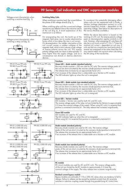
Switching Relay <strong>Coil</strong>s.<br />
When switching a resistive load, the current follows<br />
the phase of the voltage directly (Fig 1).<br />
When switching relay coils the current <strong>and</strong> voltage<br />
waveforms are different due to the inductive nature<br />
of the coil (Fig 2). A brief explanation of this<br />
mechanism is as follows.<br />
On energisating the coil, the build up of the<br />
magnetic field gives rise to counter electromotive<br />
forces which in turn delay the rise in coil current.<br />
On de-energisation, the sudden interruption of the<br />
coil current causes a sudden collapse of the<br />
magnetic field, which in turn induces a high voltage<br />
of reverse polarity across the coil. This reverse<br />
polarity voltage peak can reach a value typically 15<br />
times higher than the supply voltage, <strong>and</strong> as a<br />
consequence can disturb or destroy electronic<br />
devices.<br />
<strong>99</strong>.02.9.xxx.79 only<br />
<strong>99</strong>.02.3.000.00 only<br />
<strong>99</strong>.02.2.000.00 only<br />
Functions<br />
To counteract this potentially damaging effect,<br />
relays coils can be suppressed with a Diode, a<br />
Varistor (voltage dependent resistor) or a RC<br />
(resistor/capacitor) module – dependent on the<br />
operating voltage. (See below for descriptions of<br />
the various Modules available.)<br />
Whilst the above description is based on the<br />
working of a DC coil, the reverse polarity voltage<br />
peak on de-energisation applies similarly to AC<br />
coils. However, when energising AC coils there will<br />
also be a coil inrush current of 1.3 to 1.7 times the<br />
nominal coil current – dependent on coil size. If<br />
coils are fed via a transformer (<strong>and</strong> particularly if<br />
several are energised at the same time) then this<br />
may need to taken into account when calculating<br />
the VA rating of the transformer.<br />
Green LED + diode module (st<strong>and</strong>ard polarity)<br />
Recovery diode <strong>modules</strong> + LED are used for DC only. The reverse voltage peaks of<br />
the coil are short circuited by the recovery diode (positive to terminal A1).<br />
The release time increases by an approximate factor of 3.<br />
If an increase of the release time is undesirable use a Varistor or RC module.<br />
The LED indicator lights up when the coil is energized.<br />
Green LED + diode module (non-st<strong>and</strong>ard polarity)<br />
Recovery diode <strong>modules</strong> + LED are used for DC only. The reverse voltage peaks of<br />
the coil are short circuited by the recovery diode (positive to terminal A2).<br />
The release time increases by an approximate factor of 3.<br />
If an increase of the release time is undesirable use a Varistor or RC module.<br />
The LED indicator lights up when the coil is energized.<br />
Green LED + Varistor module<br />
LED <strong>modules</strong> + Varistor are used for both AC <strong>and</strong> DC coils.<br />
The reverse voltage peaks of the relay coil are limited by the Varistor to approximately<br />
2.5 times the nominal voltage of the supply. When using DC coils it is essential that<br />
positive is connected to terminal A1. The relay release time increases insignificantly.<br />
Green LED module<br />
LED <strong>modules</strong> are used for AC <strong>and</strong> DC.<br />
The LED indicator lights up when the coil is energized.<br />
When using DC it is essential that positive is connected to terminal A1.<br />
Diode module (st<strong>and</strong>ard polarity)<br />
Recovery diode <strong>modules</strong> are used for DC only. The reverse voltage<br />
peaks of the coil are short circuited by the recovery diode (positive to terminal A1).<br />
The release time increases by an approximate factor of 3.<br />
If an increase of the release time is undesirable use a Varistor or RC module.<br />
Diode module (non-st<strong>and</strong>ard polarity)<br />
Recovery diode <strong>modules</strong> are used for DC only. The reverse voltage<br />
peaks of the coil are short circuited by the recovery diode (positive to terminal A2).<br />
The release time increases by an approximate factor of 3.<br />
If an increase of the release time is undesirable use a Varistor or RC module.<br />
RC module<br />
RC circuit <strong>modules</strong> are used for AC <strong>and</strong> DC coils. The reverse voltage peaks<br />
of the coil are limited by the RC module to approximately 2.5 times the<br />
nominal voltage of the supply. The relay release time increases insignificantly.<br />
Residual current bypass module<br />
Bypass <strong>modules</strong> are advisable if 110 or 230v AC relays show any tendency to fail to<br />
release. Failure to release can be caused by residual currents from AC proximity<br />
switches or inductive coupling caused through long parallel lying AC control lines.