caution - Support
caution - Support
caution - Support

Create successful ePaper yourself
Turn your PDF publications into a flip-book with our unique Google optimized e-Paper software.
Proprietary Notice and Liability Disclaimer<br />
The information disclosed in this document, including all designs and related materials, is the<br />
valuable property of NEC Computer Systems Division, Packard Bell NEC, Inc. (hereinafter “NEC<br />
CSD”) and/or its licensors. NEC CSD and/or its licensors, as appropriate, reserve all patent,<br />
copyright and other proprietary rights to this document, including all design, manufacturing,<br />
reproduction, use, and sales rights thereto, except to the extent said rights are expressly granted to<br />
others.<br />
The NEC CSD product(s) discussed in this document are warranted in accordance with the terms of<br />
the Warranty Statement accompanying each product. However, actual performance of each such<br />
product is dependent upon factors such as system configuration, customer data, and operator<br />
control. Since implementation by customers of each product may vary, the suitability of specific<br />
product configurations and applications must be determined by the customer and is not warranted<br />
by NEC CSD.<br />
To allow for design and specification improvements, the information in this document is subject to<br />
change at any time, without notice. Reproduction of this document or portions thereof without prior<br />
written approval of NEC CSD is prohibited.<br />
As an ENERGY star partner, NEC Computer Systems Division (NEC CSD) has determined that this product meets the<br />
ENERGY star guidelines for energy efficiency.<br />
FaxFlash is a service mark of NEC CSD, Packard Bell NEC, Inc.<br />
NEC and PowerMate are registered trademarks of NEC Corporation, used under license.<br />
ENERGY STAR is a U.S. registered trademark.<br />
All other product, brand, or trade names used in this publication are the trademarks or registered trademarks of their<br />
respective trademark owners.<br />
First Printing — June 1998<br />
Copyright 1998<br />
NEC Computer Systems Division<br />
Packard Bell NEC, Inc.<br />
1414 Massachusetts Avenue<br />
Boxborough, MA 01719-2298<br />
All Rights Reserved
Contents<br />
Preface .............................................................................................................................ix<br />
Abbreviations...................................................................................................................xi<br />
1 System Overview<br />
Configurations............................................................................................................... 1-2<br />
Features......................................................................................................................... 1-4<br />
Front Features .......................................................................................................... 1-4<br />
Back Features........................................................................................................... 1-6<br />
Inside Features ......................................................................................................... 1-8<br />
Security Features...................................................................................................... 1-9<br />
Components .................................................................................................................1-10<br />
System Board..........................................................................................................1-10<br />
Riser Board .............................................................................................................1-11<br />
Diskette Drive .........................................................................................................1-11<br />
Hard Drive ..............................................................................................................1-11<br />
Power Supply ..........................................................................................................1-12<br />
Keyboard.................................................................................................................1-12<br />
Mouse .....................................................................................................................1-12<br />
AGP Board..............................................................................................................1-13<br />
CD-ROM Drive.......................................................................................................1-13<br />
Speakers..................................................................................................................1-13<br />
Fax/Modem Board...................................................................................................1-13<br />
Sound Board............................................................................................................1-14<br />
Local Area Network ................................................................................................1-14<br />
SCSI Adapter Board................................................................................................1-14<br />
PC Adapter Device..................................................................................................1-15<br />
Tape Backup Unit....................................................................................................1-15<br />
Zip Drive.................................................................................................................1-15<br />
2 System Configuration<br />
Interrupt Requests ......................................................................................................... 2-2<br />
System Interrupts ..................................................................................................... 2-2<br />
Parallel Port Interrupts.............................................................................................. 2-3<br />
Serial Port Interrupts ................................................................................................ 2-4<br />
Jumper Settings ............................................................................................................. 2-4<br />
System Board Jumper Settings.................................................................................. 2-5<br />
Riser Board LAN Jumper Settings............................................................................ 2-5<br />
Riser Board Fan Jumper Settings .............................................................................. 2-5<br />
Maxtor IDE Hard Drive Jumper Settings .................................................................. 2-6<br />
Quantum IDE Hard Drive Jumper Settings ............................................................... 2-6<br />
IBM IDE Hard Drive Jumper Settings ...................................................................... 2-7<br />
Seagate and Quantum SCSI Hard Drive Jumper Settings .......................................... 2-7<br />
Western Digital SCSI Hard Drive Jumper Settings.................................................... 2-8<br />
NEC 32X CD-ROM Drive Jumper Settings .............................................................. 2-8<br />
Lucky Goldstar 32X CD-ROM Drive Jumper Settings.............................................. 2-9<br />
56-Kbps Fax/Modem Board Jumper Settings ............................................................ 2-9<br />
Zip Drive Jumper Settings ........................................................................................ 2-9<br />
Tape Backup Unit Jumper Settings ..........................................................................2-10<br />
Contents iii
BIOS Setup ..................................................................................................................2-10<br />
When to Use BIOS Setup ........................................................................................2-10<br />
How to Start BIOS Setup.........................................................................................2-11<br />
How to Use Setup....................................................................................................2-12<br />
Main Menu..............................................................................................................2-12<br />
Displayed Information .................................................................................... 2-12<br />
Language........................................................................................................ 2-13<br />
ECC Configuration ......................................................................................... 2-13<br />
L2 Cache ECC <strong>Support</strong>................................................................................... 2-13<br />
System Time/Date........................................................................................... 2-13<br />
Advanced Menu ......................................................................................................2-13<br />
Plug & Play O/S ............................................................................................. 2-13<br />
Reset Configuration Data................................................................................ 2-13<br />
Numlock......................................................................................................... 2-13<br />
Peripheral Configuration................................................................................. 2-14<br />
IDE Configuration .......................................................................................... 2-16<br />
Floppy Options ............................................................................................... 2-17<br />
DMI Event Logging........................................................................................ 2-18<br />
Video Configuration ....................................................................................... 2-19<br />
Resource Configuration................................................................................... 2-19<br />
Keyboard Configuration.................................................................................. 2-20<br />
Security Menu.........................................................................................................2-20<br />
Power Menu............................................................................................................2-21<br />
Boot Menu ..............................................................................................................2-22<br />
Exit Menu ...............................................................................................................2-24<br />
Maintenance Menu..................................................................................................2-24<br />
Video Modes................................................................................................................2-25<br />
Utilities ........................................................................................................................2-26<br />
SCSISelect Utility ...................................................................................................2-26<br />
BIOS Update Utility................................................................................................2-26<br />
LANDESK Client Manager.....................................................................................2-27<br />
PC Health Indicator......................................................................................... 2-28<br />
Inventory ........................................................................................................ 2-29<br />
DMI................................................................................................................ 2-29<br />
Monitoring Capabilities................................................................................... 2-30<br />
Using the Chassis Intrusion Notification Feature............................................. 2-30<br />
NEC Auto Backup...................................................................................................2-31<br />
NEC Select Install CD.............................................................................................2-31<br />
Choosing a Restore Program........................................................................... 2-32<br />
Rebuilding the Hard Drive and Restoring the Operating System...................... 2-33<br />
Auto Rebuild and Restore ............................................................................... 2-33<br />
Custom Rebuild and Restore........................................................................... 2-36<br />
Restoring the Operating System ...................................................................... 2-40<br />
Installing Applications .................................................................................... 2-42<br />
Using the NEC Select Install CD with a SCSI Drive........................................ 2-44<br />
Using the Selective Application Restore Program on a Remote CD ................. 2-44<br />
NEC Help Center Online Documentation.................................................................2-46<br />
Installing the NEC Help Center Online Documentation................................... 2-46<br />
Uninstalling the NEC Help Center .................................................................. 2-46<br />
NEC Driver CD.......................................................................................................2-47<br />
Installing Drivers With the NEC Driver CD .................................................... 2-47<br />
Installing Drivers From a Remote CD ............................................................. 2-47<br />
Cheyenne Backup....................................................................................................2-49<br />
iv Contents
NEC Security ..........................................................................................................2-49<br />
NEC SNMP Agent ..................................................................................................2-50<br />
Installing the NEC SNMP Agent..................................................................... 2-50<br />
Configuring the NEC SNMP Agent for Windows 95....................................... 2-51<br />
Configuring the NEC SNMP Agent for Windows NT ..................................... 2-52<br />
NEC WebTelligent..................................................................................................2-53<br />
NEC WebTelligent Features............................................................................ 2-53<br />
NEC WebTelligent Requirements ................................................................... 2-54<br />
NEC WebTelligent Installation ....................................................................... 2-55<br />
NEC Configuration Change Notification..................................................................2-58<br />
3 Disassembly and Reassembly<br />
System Unit Cover Removal.......................................................................................... 3-3<br />
Removing the System Unit Cover............................................................................. 3-4<br />
Replacing the System Unit Cover ............................................................................. 3-6<br />
Chassis Floor Removal.................................................................................................. 3-7<br />
Removing the Chassis Floor ..................................................................................... 3-7<br />
Replacing the Chassis Floor...................................................................................... 3-8<br />
Removing the Stand ................................................................................................. 3-9<br />
Replacing the Stand.................................................................................................3-10<br />
Expansion Board Removal ...........................................................................................3-11<br />
Front Panel Removal ....................................................................................................3-12<br />
Blank Panel and Metal Slot Cover Removal..................................................................3-13<br />
Expansion Board Guide Removal .................................................................................3-14<br />
Switch Board/IR Panel Assembly Removal ..................................................................3-14<br />
DIMM Module Removal ..............................................................................................3-15<br />
AGP Board Removal....................................................................................................3-16<br />
Processor Subsystem Removal......................................................................................3-17<br />
5 1/4-Inch Device Removal ..........................................................................................3-18<br />
3 1/2-Inch Hard Drive Removal....................................................................................3-19<br />
3 1/2-Inch Diskette Drive Removal...............................................................................3-20<br />
Power Supply Removal ................................................................................................3-21<br />
System Board Removal and Replacement.....................................................................3-22<br />
System Board Removal ...........................................................................................3-22<br />
System Board Replacement .....................................................................................3-23<br />
Plastic Rail Removal ...............................................................................................3-25<br />
Riser Board Removal....................................................................................................3-26<br />
CMOS Battery Removal...............................................................................................3-27<br />
4 System Board<br />
Connectors, Jumpers, and Sockets ................................................................................. 4-2<br />
External Cable Connectors ....................................................................................... 4-2<br />
Internal Connectors .................................................................................................. 4-3<br />
System Board Jumpers ............................................................................................. 4-4<br />
Changing Processor Speed .............................................................................. 4-4<br />
Clearing a Password........................................................................................ 4-6<br />
BIOS Recovery............................................................................................... 4-7<br />
Upgrade Sockets....................................................................................................... 4-8<br />
Processor Socket............................................................................................. 4-8<br />
DIMM Sockets ............................................................................................... 4-8<br />
Checking System Memory .............................................................................. 4-10<br />
Contents v
Components .................................................................................................................4-10<br />
Processor and Secondary Cache...............................................................................4-12<br />
System BIOS...........................................................................................................4-13<br />
System Memory ......................................................................................................4-13<br />
Hardware Monitor ...................................................................................................4-14<br />
Plug and Play ..........................................................................................................4-14<br />
NLX Design............................................................................................................4-14<br />
ISA Bus...................................................................................................................4-14<br />
PCI Local Bus.........................................................................................................4-15<br />
PCI/IDE Ports .........................................................................................................4-15<br />
Parallel Interface .....................................................................................................4-15<br />
Serial Interface ........................................................................................................4-16<br />
USB Interface..........................................................................................................4-17<br />
Infrared Interface.....................................................................................................4-17<br />
Graphics Capabilities...............................................................................................4-17<br />
Accelerated Graphics Port .......................................................................................4-18<br />
Graphics Controller .................................................................................................4-18<br />
Motion Video Controller .........................................................................................4-18<br />
Graphics <strong>Support</strong>.....................................................................................................4-18<br />
Integrated Audio......................................................................................................4-19<br />
Pin Assignments...........................................................................................................4-20<br />
Parallel Interface Connector.....................................................................................4-20<br />
Serial Interface Connectors......................................................................................4-21<br />
Keyboard and Mouse Connectors ............................................................................4-21<br />
Universal Serial Bus Connectors..............................................................................4-22<br />
VGA Interface Connector........................................................................................4-22<br />
Microphone In Connector........................................................................................4-23<br />
Line In Connector....................................................................................................4-23<br />
Line Out Connector .................................................................................................4-23<br />
DIMM Sockets........................................................................................................4-24<br />
Resources.....................................................................................................................4-25<br />
Memory Map ..........................................................................................................4-25<br />
I/O Addresses..........................................................................................................4-26<br />
DMA Settings .........................................................................................................4-28<br />
5 Riser Board<br />
Subsystem Cable Connectors......................................................................................... 5-3<br />
CD Audio In Connector............................................................................................ 5-3<br />
Modem In Connector................................................................................................ 5-3<br />
Wake-On LAN Connector ........................................................................................ 5-4<br />
Chassis Intrusion Detection Connector ..................................................................... 5-4<br />
Front Panel/IrDA Connector..................................................................................... 5-4<br />
Fan Connector.......................................................................................................... 5-5<br />
LAN Connector........................................................................................................ 5-5<br />
IDE and Diskette Drive Cable Connectors ..................................................................... 5-6<br />
IDE Connectors........................................................................................................ 5-6<br />
Diskette Drive Connector ......................................................................................... 5-7<br />
PCI and ISA Cable Connectors...................................................................................... 5-8<br />
PCI Connectors ........................................................................................................ 5-8<br />
ISA Bus Connector................................................................................................... 5-9<br />
NLX Connector P1 (PCI Segment) ..........................................................................5-10<br />
NLX Connector P1 (ISA Segment)..........................................................................5-14<br />
NLX Connector P1 (IDE, Diskette Drive, and Front Panel Segment) .......................5-17<br />
vi Contents
NLX Connector JP2 (Supplemental Connector Segment).........................................5-22<br />
Power Supply Cable Connectors...................................................................................5-23<br />
Jumper Settings ............................................................................................................5-24<br />
LAN Jumper Settings ..............................................................................................5-24<br />
Fan Jumper Settings ................................................................................................5-25<br />
Changing Jumpers...................................................................................................5-25<br />
6 Illustrated Parts Breakdown<br />
Parts and Options .......................................................................................................... 6-2<br />
Field Replaceable Unit (FRU) List................................................................................. 6-2<br />
Illustrated Parts Breakdown (IPB).................................................................................. 6-5<br />
7 Preventive Maintenance<br />
System Cleaning............................................................................................................ 7-2<br />
Keyboard Cleaning........................................................................................................ 7-2<br />
Mouse Cleaning ............................................................................................................ 7-3<br />
8 Troubleshooting<br />
Checklist .......................................................................................................................8-2<br />
System Problems...................................................................................................... 8-2<br />
Diskette Drive Problems........................................................................................... 8-3<br />
Monitor Problems..................................................................................................... 8-4<br />
Keyboard/Mouse Problems....................................................................................... 8-4<br />
CD-ROM Drive Problems ........................................................................................ 8-5<br />
Speaker Problems..................................................................................................... 8-5<br />
Diagnostics.................................................................................................................... 8-6<br />
9 NEC CSD Information Services<br />
Service Telephone Numbers .......................................................................................... 9-2<br />
Technical <strong>Support</strong> ......................................................................................................... 9-3<br />
NEC CSD Website................................................................................................... 9-3<br />
Email/Fax Technical <strong>Support</strong> Service ....................................................................... 9-3<br />
Technical <strong>Support</strong> Services....................................................................................... 9-4<br />
Product Information....................................................................................................... 9-4<br />
NEC CSD FTP Site.................................................................................................. 9-4<br />
NEC CSD Bulletin Board Service............................................................................. 9-5<br />
FaxFlash Service ........................................................................................................... 9-6<br />
10 Specifications<br />
System Board Specifications ........................................................................................10-3<br />
Riser Board Specifications............................................................................................10-4<br />
Keyboard Specifications...............................................................................................10-4<br />
Mouse Specifications....................................................................................................10-5<br />
Speaker Specifications..................................................................................................10-5<br />
System Unit Specifications...........................................................................................10-6<br />
Diskette Drive Specifications........................................................................................10-7<br />
3.2-GB Quantum Hard Drive Specifications .................................................................10-8<br />
3.2-GB Maxtor Hard Drive Specifications ....................................................................10-9<br />
4.3-GB Quantum Hard Drive Specifications ...............................................................10-10<br />
4.3-GB Maxtor Hard Drive Specifications ..................................................................10-11<br />
6.4-GB Quantum Hard Drive Specifications ...............................................................10-12<br />
Contents vii
6.4-GB Maxtor Hard Drive Specifications ..................................................................10-13<br />
8.4-GB Maxtor Hard Drive Specifications ..................................................................10-14<br />
8.4-GB Quantum Hard Drive Specifications ...............................................................10-15<br />
8.4-GB IBM Hard Drive Specifications ......................................................................10-16<br />
4.5-GB Quantum SCSI Hard Drive Specifications ......................................................10-17<br />
4.5-GB Seagate SCSI Hard Drive Specifications.........................................................10-18<br />
9.1-GB Western Digital SCSI Hard Drive Specifications ............................................10-19<br />
NLX200-Watt Power Supply Specifications ...............................................................10-20<br />
Fax/Modem Board Specifications...............................................................................10-20<br />
ATI Xpert@Work AGP Board Specifications.............................................................10-21<br />
AccelGRAPHICS AccelSTAR II 2D/3D AGP Board Specifications...........................10-21<br />
Lucky Goldstar 32X CD-ROM Drive Specifications...................................................10-22<br />
NEC 32X CD-ROM Drive Specifications...................................................................10-23<br />
Sound Board Specifications........................................................................................10-24<br />
PC Adapter Device Specifications ..............................................................................10-25<br />
Tape Backup Unit Specifications................................................................................10-25<br />
Zip Drive Specifications.............................................................................................10-26<br />
Environmental and Safety Specifications ....................................................................10-27<br />
Compliance ................................................................................................................10-28<br />
A Release Notes<br />
General Notes................................................................................................................A-2<br />
Installing Applications and Online Documentation ...................................................A-2<br />
Choosing the Correct Installation Method ....................................................... A-2<br />
Installing Applications in the Correct Order .................................................... A-2<br />
Uninstalling the NEC SNMP Agent or LANDesk Client Manager ............................A-3<br />
Correcting Video Corruption ....................................................................................A-4<br />
Correcting Video Corruption in a Windows 95 System.................................... A-4<br />
Correcting Video Corruption in a Windows NT System .................................. A-5<br />
Setting Boot Order in BIOS......................................................................................A-5<br />
Using 16-MB DIMMs ..............................................................................................A-5<br />
Configuring the System for the NEC SNMP Agent...................................................A-5<br />
Configuring the System for NEC WebTelligent ........................................................A-5<br />
Configuring the System for Microsoft Internet Explorer............................................A-6<br />
Changing Network Settings ......................................................................................A-6<br />
SCSI Drive Limitations .................................................................................................A-7<br />
Booting from a CD...................................................................................................A-7<br />
Using the NEC Select Install CD with a SCSI Drive .................................................A-7<br />
PIIX4 Limitations..........................................................................................................A-7<br />
Reconfiguring Ultra DMA <strong>Support</strong>...........................................................................A-7<br />
Determining IDE Device Compatibility....................................................................A-8<br />
Windows 95 Issues........................................................................................................A-8<br />
Controlling CD Audio ..............................................................................................A-8<br />
Using Cheyenne Backup...........................................................................................A-8<br />
Backing Up Large Drives................................................................................ A-8<br />
Using Cheyenne Backup with LANDesk Client Manager................................ A-8<br />
Clicking the Product Catalog Button.........................................................................A-9<br />
Glossary<br />
Index<br />
viii Contents
List of Figures<br />
PowerMate 8100 Series System Components ........................................................................ 1-2<br />
PowerMate 8100 Series System Front View.......................................................................... 1-4<br />
System Controls and Lamps.................................................................................................. 1-4<br />
PowerMate 8100 Series System Back View .......................................................................... 1-6<br />
Audio Connectors ................................................................................................................. 1-6<br />
Inside the System.................................................................................................................. 1-8<br />
BIOS Setup Main Menu.......................................................................................................2-11<br />
Welcome Screen ..................................................................................................................2-34<br />
NEC Selective Application Restore Screen...........................................................................2-43<br />
NEC WebTelligent...............................................................................................................2-53<br />
NEC WebTelligent Login Screen.........................................................................................2-57<br />
NEC WebTelligent Control Screen.......................................................................................2-58<br />
Loosening Cover Screws....................................................................................................... 3-4<br />
Removing the Cover ............................................................................................................. 3-5<br />
Aligning the Cover................................................................................................................ 3-6<br />
Locating the Chassis Floor Thumb Screw.............................................................................. 3-7<br />
Removing the Chassis Floor.................................................................................................. 3-8<br />
Removing the Stand..............................................................................................................3-9<br />
Aligning the System Unit With the Stand.............................................................................3-10<br />
Securing the System Unit in the Stand..................................................................................3-10<br />
Removing the Expansion Board ...........................................................................................3-11<br />
Removing the Front Panel....................................................................................................3-12<br />
Removing the Blank Panel...................................................................................................3-13<br />
Removing a DIMM Module.................................................................................................3-15<br />
Removing the AGP Board....................................................................................................3-16<br />
Releasing the Processor Subsystem......................................................................................3-17<br />
Locating the Locking Tabs...................................................................................................3-18<br />
Removing a 5 1/4-Inch Device.............................................................................................3-18<br />
Removing the Inner Hard Drive Screws ...............................................................................3-19<br />
Removing the Outer Hard Drive Screws...............................................................................3-20<br />
Removing the Power Supply Screws ....................................................................................3-21<br />
Unlatching the System Board...............................................................................................3-22<br />
Removing the System Board................................................................................................3-22<br />
Correct Alignment of the System Board...............................................................................3-23<br />
Incorrect Alignment of the System Board.............................................................................3-24<br />
Secured Position of Latch.....................................................................................................3-25<br />
Removing the System Board Plastic Rail..............................................................................3-25<br />
Locating the Riser Board Screws..........................................................................................3-26<br />
Locating the Battery.............................................................................................................3-27<br />
Removing the Battery ..........................................................................................................3-28<br />
System Board External Cable Connector Locations............................................................... 4-2<br />
System Board Internal Connector Locations.......................................................................... 4-3<br />
Locating Configuration Jumper Block J5G1.......................................................................... 4-4<br />
Subsystem Cable Connector Locations.................................................................................. 5-3<br />
IDE and Diskette Drive Cable Connectors............................................................................. 5-6<br />
PCI and ISA Cable Connector Locations............................................................................... 5-8<br />
Riser Board Power Supply Cable Connector Locations.........................................................5-23<br />
Riser Board Jumper Locations..............................................................................................5-24<br />
Contents ix
PowerMate 8100 Series Computer Illustrated Parts Breakdown............................................. 6-5<br />
Removing the Keyboard Enclosure ....................................................................................... 7-3<br />
Removing the Mouse Ball Cover........................................................................................... 7-3<br />
List of Tables<br />
PowerMate 8100 Series System Configuration...................................................................... 1-3<br />
System Components.............................................................................................................1-10<br />
Interrupt Level Assignments ................................................................................................. 2-3<br />
Parallel Port Interrupts .......................................................................................................... 2-3<br />
Serial Port 1 and Serial Port 2 Interrupts................................................................................ 2-4<br />
System Board Jumper J5G1 Settings ..................................................................................... 2-5<br />
Riser Board LAN Jumper JP7 Settings.................................................................................. 2-5<br />
Fan Jumper Block JP3 Settings ............................................................................................. 2-5<br />
Maxtor IDE Hard Drive Jumper Settings............................................................................... 2-6<br />
Quantum IDE Hard Drive Jumper Settings............................................................................ 2-6<br />
IBM IDE Hard Drive Jumper Settings................................................................................... 2-7<br />
Seagate and Quantum SCSI Hard Drive Jumper Settings....................................................... 2-7<br />
Western Digital SCSI Hard Drive Jumper Settings ................................................................ 2-8<br />
NEC 32X CD-ROM Drive Jumper Settings........................................................................... 2-8<br />
Lucky Goldstar 32X CD-ROM Drive Jumper Settings .......................................................... 2-9<br />
56-Kbps Fax/Modem Board Jumper Settings (Windows NT Only)........................................ 2-9<br />
Zip Drive Jumper Settings..................................................................................................... 2-9<br />
Tape Backup Unit Jumper Settings.......................................................................................2-10<br />
Navigation Keys ..................................................................................................................2-12<br />
Peripheral Configuration Parameters....................................................................................2-14<br />
IDE Device Configuration Parameters..................................................................................2-16<br />
Floppy Drive Options...........................................................................................................2-17<br />
DMI Event Logging.............................................................................................................2-18<br />
Video Configuration ............................................................................................................2-19<br />
Resource Configuration........................................................................................................2-19<br />
Keyboard Configuration.......................................................................................................2-20<br />
Security Menu Options ........................................................................................................2-20<br />
Power Menu Options ...........................................................................................................2-21<br />
Boot Menu Options..............................................................................................................2-22<br />
Exit Menu Options...............................................................................................................2-24<br />
Maintenance Menu Options .................................................................................................2-24<br />
System Utilities....................................................................................................................2-26<br />
PowerMate 8100 Series Disassembly Sequence..................................................................... 3-2<br />
System Board Internal Connectors ........................................................................................ 4-3<br />
<strong>Support</strong>ed DIMMs ................................................................................................................ 4-9<br />
Sample DIMM Upgrade Paths .............................................................................................. 4-9<br />
System Board Components ..................................................................................................4-11<br />
Parallel Port Addresses ........................................................................................................4-16<br />
Serial Port 1 and Serial Port 2 I/O Addresses........................................................................4-16<br />
ATI XPERT@Work 2D Display Modes and Refresh Rates..................................................4-19<br />
ATI XPERT@Work 3D Display Modes...............................................................................4-19<br />
Parallel Interface Pin Assignments .......................................................................................4-20<br />
Serial Interface Pin Assignments..........................................................................................4-21<br />
x Contents
Keyboard and Mouse Pin Assignments ................................................................................4-21<br />
Universal Serial Bus Connector Pin Assignments.................................................................4-22<br />
VGA Interface Connector Pin Assignments..........................................................................4-22<br />
Microphone In Connector Pin Assignments..........................................................................4-23<br />
Line In Connector Pin Assignments .....................................................................................4-23<br />
Line Out Connector Pin Assignments..................................................................................4-23<br />
DIMM Socket Pin Assignments ...........................................................................................4-24<br />
System Memory Map...........................................................................................................4-26<br />
I/O Address Map .................................................................................................................4-26<br />
DMA Settings......................................................................................................................4-28<br />
CD Audio In Connector JP6 Pin Assignments ....................................................................... 5-3<br />
Modem In Connector JP1 Pin Assignments........................................................................... 5-3<br />
Wake-On LAN Connector J5 Pin Assignments...................................................................... 5-4<br />
Chassis Intrusion Detection Connector J6 Pin Assignments................................................... 5-4<br />
Front Panel/IrDA Connector J4 Pin Assignments .................................................................. 5-4<br />
Fan Connector J9 Pin Assignments ....................................................................................... 5-5<br />
LAN Connector RJ-45 Pin Assignments................................................................................ 5-5<br />
IDE Interface Pin Assignments ............................................................................................. 5-6<br />
Diskette Drive Pin Assignments............................................................................................ 5-7<br />
PCI Bus Pin Assignments...................................................................................................... 5-8<br />
ISA Bus Connector Pin Assignments .................................................................................... 5-9<br />
NLX Connector P1 Pin Assignments (PCI Segment)............................................................5-10<br />
NLX Connector P1 Pin Assignments (ISA Segment)............................................................5-14<br />
NLX Connector P1 Pin Assignments (IDE, Diskette Drive, and Front Panel Segment) .........5-17<br />
NLX Connector JP2 Pin Assignments (Supplemental Connector Segment)...........................5-22<br />
Power Supply Main Power Connector Pin Assignments .......................................................5-23<br />
Power Supply Optional Power Connector Pin Assignments..................................................5-24<br />
LAN Jumper Block JP7 Settings ..........................................................................................5-24<br />
Fan Jumper Block JP3 Settings ............................................................................................5-25<br />
Ordering Parts and Options ................................................................................................... 6-2<br />
PowerMate 8100 Series System FRU List ............................................................................. 6-2<br />
PowerMate 8100 Series System Documentation and Packaging............................................. 6-5<br />
Problems and Solutions......................................................................................................... 8-6<br />
NEC CSD Service and <strong>Support</strong> Telephone Numbers ............................................................. 9-2<br />
System Specifications ..........................................................................................................10-2<br />
System Board Specifications................................................................................................10-3<br />
Riser Board Specifications ...................................................................................................10-4<br />
Keyboard Specifications ......................................................................................................10-4<br />
Mouse Specifications ...........................................................................................................10-5<br />
Speaker Specification...........................................................................................................10-5<br />
System Unit Specifications...................................................................................................10-6<br />
Diskette Drive Specifications ...............................................................................................10-7<br />
3.2-GB Quantum Fireball ST Hard Drive Specifications.......................................................10-8<br />
3.2-GB Maxtor DiamondMax Hard Drive Specifications......................................................10-9<br />
4.3-GB Quantum Fireball SE Hard Drive Specifications.....................................................10-10<br />
4.3-GB Maxtor DiamondMax Hard Drive Specifications....................................................10-11<br />
6.4-GB Quantum Fireball ST Hard Drive Specifications.....................................................10-12<br />
6.4-GB Maxtor DiamondMax Hard Drive Specifications....................................................10-13<br />
8.4-GB Maxtor DiamondMax Hard Drive Specifications....................................................10-14<br />
Contents xi
8.4-GB Maxtor DiamondMax Hard Drive Specifications....................................................10-15<br />
8.4-GB IBM DHEA Hard Drive Specifications ..................................................................10-16<br />
4.5-GB Quantum Viking Ultra Wide SCSI-3 Hard Drive Specifications.............................10-17<br />
4.5-GB Seagate Barracuda Ultra Wide SCSI Hard Drive Specifications .............................10-18<br />
9.1-GB Western Digital Ultra Wide SCSI Hard Drive Specifications..................................10-19<br />
NLX200 Watt Power Supply Specifications .......................................................................10-20<br />
Fax/Modem Board Specifications.......................................................................................10-20<br />
ATI Xpert@Work (RagePRO) AGP Board Specifications..................................................10-21<br />
AccelSTAR II 2D/3D AGP Board Specifications ...............................................................10-21<br />
Lucky Goldstar 32X CD-ROM Drive Specifications ..........................................................10-22<br />
NEC 32X CD-ROM Drive Specifications ..........................................................................10-23<br />
Sound Board Specifications ...............................................................................................10-24<br />
PC Adapter Device Specifications......................................................................................10-25<br />
Tape Backup Unit Specifications........................................................................................10-25<br />
Zip Drive Specification......................................................................................................10-26<br />
Specifications ....................................................................................................................10-27<br />
System Compliance ...........................................................................................................10-28<br />
xii Contents
Preface<br />
This manual contains technical information for servicing and repairing the NEC<br />
PowerMate ® 8100 Series computers manufactured by NEC Computer Systems<br />
Division, Packard Bell NEC, Inc. The manual contains hardware and interface<br />
information for users who need an overview of system design. The manual<br />
includes system setup information, disassembly procedures, and illustrated parts<br />
lists. The manual is prepared for NEC CSD trained customer engineers, system<br />
analysts, service center personnel, and dealers.<br />
The manual is organized as follows.<br />
Section 1 — System Overview, provides an overview of system features and<br />
includes brief descriptions of system components.<br />
Section 2 — System Configuration, includes information on system IRQs,<br />
jumpers, and BIOS. The section also contains information on video modes and<br />
power management features. Also included is information on system utilities,<br />
including the SCSISelect utility, BIOS update utility, LANDesk ® Client<br />
Manager, and NEC Select Install CD.<br />
Section 3 — Disasssembly and Reassembly, provides computer disassembly<br />
and reassembly procedures. Each procedure is supported by detailed<br />
disassembly illustrations.<br />
Section 4 — System Board, includes information on cable and board<br />
connectors, jumper settings, and upgrade sockets. Also provided is information<br />
on board components, pin assignments, and memory map.<br />
Section 5 — Riser Board, provides cable connector information and pin<br />
assignments for the riser board installed in the system.<br />
Section 6 — Illustrated Parts Breakdown, includes an exploded view diagram<br />
(illustrated parts breakdown) and parts lists for field-replaceable parts.<br />
Section 7 — Preventive Maintenance, provides recommended maintenance<br />
information for maintaining the system in top condition.<br />
Section 8 — Troubleshooting, includes information for solving possible<br />
computer problems and their solutions.<br />
Section 9 — NEC CSD Information Services, lists telephone numbers for<br />
obtaining service. The section also includes information on NEC CSD technical<br />
support, website, bulletin board service, and FaxFlash SM service.<br />
Section 10 — Specifications, provides specifications on the major components<br />
in the system, including the system board, power supply, diskette drive, and<br />
hard drives.<br />
Appendix A — NEC PowerMate 8100 Series Release Notes, describes<br />
recommended operating procedures not documented in other PowerMate 8100<br />
Series documentation.<br />
Preface xiii
Abbreviations<br />
A ampere<br />
AC alternating current<br />
ACK acknowledge<br />
AGP accelerated graphics port<br />
ASIC application-specific<br />
integrated circuit<br />
AT advanced technology<br />
(IBM PC)<br />
ATA AT attachment<br />
ATAPI AT attachment packet<br />
interface<br />
ATM asynchronous transfer mode<br />
BBS Bulletin Board Service<br />
BCD binary-coded decimal<br />
BCU BIOS Customized Utility<br />
BIOS basic input/output system<br />
bit binary digit<br />
BUU BIOS Upgrade Utility<br />
bpi bits per inch<br />
bps bits per second<br />
C capacitance<br />
C centigrade<br />
Cache high-speed buffer storage<br />
CAM constantly addressable<br />
memory<br />
CAS column address strobe<br />
CD-ROM compact disk-ROM<br />
CH channel<br />
clk clock<br />
cm centimeter<br />
CMOS complementary metal oxide<br />
semiconductor<br />
COM communication<br />
CONT contrast<br />
CPGA ceramic pin grid array<br />
CPU central processing unit<br />
DAC digital-to-analog converter<br />
DACK DMA acknowledge<br />
dB decibels<br />
DC direct current<br />
DCC direct cable connection<br />
DCE data communications<br />
equipment<br />
DDC Display Data Channel<br />
DIMM Dual In-Line Memory Module<br />
DIP dual in-line package<br />
DMA direct memory access<br />
DMAC DMA controller<br />
DMI Desktop Management<br />
Interface<br />
DOS disk operating system<br />
DRAM dynamic RAM<br />
DVD digital versatile disc<br />
ECC error checking and correction<br />
ECP extended capabilities port<br />
EDO extended data output<br />
EGA Enhanced Graphics Adapter<br />
EISA enhanced ISA<br />
email electronic mail<br />
EMI electromagnetic interference<br />
EPP enhanced parallel port<br />
EPROM erasable and programmable<br />
ROM<br />
ESD electrostatic discharge<br />
EVGA Enhanced Video Graphics<br />
Array<br />
F Fahrenheit<br />
FAX facsimile transmission<br />
FCC Federal Communications<br />
Commission<br />
FG frame ground<br />
FM frequency modulation<br />
FP fast page<br />
FRU field-replaceable unit<br />
ftp file transfer protocol<br />
GB gigabyte<br />
Abbreviations xv
GND ground<br />
HEX hexadecimal<br />
HGA Hercules Graphics Adapter<br />
Hz hertz<br />
IC integrated circuit<br />
ID identification<br />
IDE intelligent device electronics<br />
IDTR interrupt descriptor table<br />
register<br />
in. inch<br />
INTA interrupt acknowledge<br />
I/O input/output<br />
IPB illustrated parts breakdown<br />
IPC integrated peripheral<br />
controller<br />
ips inches per second<br />
IR infrared<br />
IrDA Infrared Data Association<br />
IRR Interrupt Request register<br />
ISA Industry Standard<br />
Architecture<br />
ISP internet service provider<br />
IRQ interrupt request<br />
K kilo (1024)<br />
k kilo (1000)<br />
KB kilobyte<br />
kg kilogram<br />
kHz kilohertz<br />
lb pound<br />
LAN local area network<br />
LED light-emitting diode<br />
LDCM LANDesk Client Manager<br />
LSB least-significant bit<br />
LSI large-scale integration<br />
M mega (million)<br />
mA milliamps<br />
max maximum<br />
MB megabyte<br />
MFM modified frequency<br />
modulation<br />
MHz megahertz<br />
xvi Abbreviations<br />
MIDI musical instrument digital<br />
interface<br />
mm millimeter<br />
MMX multimedia extensions<br />
modem modulator/demodulator<br />
MOS metal-oxide semiconductor<br />
MPEG Motion Picture Experts Group<br />
ms millisecond<br />
MSB most-significant bit<br />
NC not connected<br />
NIC networked information center<br />
NMI Non-maskable Interrupt<br />
ns nanosecond<br />
NSRC National Service Response<br />
Center<br />
OCR optical character recognition<br />
OS operating system<br />
PAL programmable array logic<br />
PC personal computer<br />
PCB printed circuit board<br />
PCI Peripheral Component<br />
Interconnect<br />
PDA personal digital assistant<br />
PFP plastic flat package<br />
PIO parallel input/output<br />
pixel picture element<br />
PLCC plastic leaded chip carrier<br />
PLL phase lock loop<br />
POST Power-On Self-Test<br />
p-p peak-to-peak<br />
PPI programmable peripheral<br />
interface<br />
PROM programmable ROM<br />
PS/2 personal system/2<br />
QFP quad flat pack<br />
R read<br />
RAM random-access memory<br />
RAMDAC RAM digital-to-analog<br />
converter<br />
RAS row address strobe<br />
RGB red green blue
RGBI red green blue intensity<br />
rms root mean square<br />
ROM read-only memory<br />
rpm revolutions per minute<br />
RTC real-time clock<br />
R/W read/write<br />
S slave<br />
SCSI Small Computer System<br />
Interface<br />
SDRAM synchronous dynamic random<br />
access memory<br />
S.E.C. single edge contact cartridge<br />
SG signal ground<br />
SGRAM synchronous graphics random<br />
access memory<br />
SIMM single inline memory module<br />
S/N signal to noise ratio<br />
SNMP simple network management<br />
protocol<br />
SPM standard page mode<br />
SRAM static random access memory<br />
SRS Sound Retrieval System<br />
SSI small scale integration<br />
SVGA Super Video Graphics Array<br />
SW switch<br />
T&D test and diagnostics<br />
TSC Technical <strong>Support</strong> Center<br />
TTL transistor/transistor logic<br />
tpi tracks per inch<br />
UART universal asynchronous<br />
receiver/transmitter<br />
UHF ultra high frequency<br />
UL Underwriter’s Laboratories<br />
UMA unified memory architecture<br />
UPS uninterruptible power supply<br />
URL uniform resource locator<br />
USB universal serial bus<br />
V volt<br />
Vac volts, alternating current<br />
VCR video cassette recorder<br />
Vdc volts, direct current<br />
VDT video display terminal<br />
VESA video electronics standards<br />
association<br />
VFC VESA-compliant feature<br />
connector<br />
VGA Video Graphics Array<br />
VHF very high frequency<br />
VLSI very large scale integration<br />
VRAM video RAM<br />
W watt<br />
WAN wide area network<br />
WRAM Windows RAM<br />
W write<br />
www world wide web<br />
Abbreviations xvii
System Overview<br />
� Configurations<br />
� Features<br />
� Components<br />
1
This section provides an overview of the NEC PowerMate ® 8100 Series<br />
minitower computer system configurations. The section highlights system<br />
hardware features, computer front, back, and inside features, and system<br />
security features. Also included are brief descriptions of the major components<br />
comprising the system.<br />
Configurations<br />
NEC PowerMate 8100 Series computer systems are built-to-order systems for<br />
commercial offices. The systems feature an Intel ® Pentium ® II processor, three<br />
dual inline memory module (DIMM) sockets, synchronous dynamic random<br />
access memory (SDRAM), and a plug and play input/output (I/O) controller.<br />
The system also features two universal serial bus (USB) ports, two serial ports, a<br />
parallel port, and an infrared port. Ultra direct memory access (DMA), remote<br />
wakeup (“Wake-On LAN”), accelerated graphics port (AGP), and power<br />
management are supported.<br />
Build choices include intelligent device electronics (IDE) hard drives ranging<br />
from 3.2 gigabyte (GB) to 8.4 GB, and an ultra wide SCSI 4.55-GB or 9.1-GB<br />
hard drive. System memory is provided in 32-megabyte (MB) (minimum) and<br />
(as available) 64-MB and 128-MB DIMM modules. Memory configurations<br />
range from 32 MB to 384 MB.<br />
Additional build choices include fax/modem, sound, video, and peripheral<br />
devices such as CD-ROM drives.<br />
The NLX system design leaves the system board free of internal cabling and<br />
allows easy system board removal and replacement with a simple chassis latch.<br />
The following figure shows the components shipped with the PowerMate 8100<br />
Series system (the monitor and speakers are optional).<br />
1-2 System Overview<br />
PowerMate 8100 Series System Components
The following table lists the PowerMate 8100 series system configuration.<br />
Component Description<br />
PowerMate 8100 Series System Configuration<br />
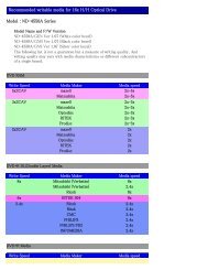
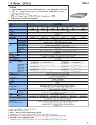
System Board Intel NX440BX with sound<br />
CPU* Pentium II 266 MHz MMX (66 MHz external)<br />
Pentium II 300 MHz MMX (66 MHz external)<br />
Pentium II 333 MHz MMX (66 MHz external)<br />
Pentium II 350 MHz MMX (100 MHz external)<br />
Pentium II 400 MHz MMX (100 MHz external)<br />
System RAM* 32 MB (minimum) to 384 MB of SDRAM in 3 DIMM sockets<br />
Hard Drive* IDE Ultra DMA/33:<br />
3.2 GB (Maxtor 83240D3, Quantum ST32A011, SE32A012)<br />
4.3 GB (Maxtor 84320D4, Quantum SE43A012)<br />
6.4 GB (Maxtor 86480D6, Quantum ST64A011, SE640A012)<br />
8.4 GB (Maxtor 88400D8, Quantum SE84A012, IBM DHEA-38451)<br />
Ultra Wide SCSI<br />
4.55 GB (Seagate ST34572W, Quantum VK45W012)<br />
9.1 GB (Western Digital WDE91000-0007A3)<br />
Cache 512-KB Pipeline Burst SRAM integrated on processor cartridge<br />
AGP Slot AGP slot on system board supports AGP-compatible graphics boards<br />
Graphics Memory System board: 4 MB synchronous graphics random-access memory (SGRAM)<br />
Graphics board: 4 MB or 8 MB SGRAM (depending on board installed)<br />
Audio Crystal CS4235B audio chip integrated on system board<br />
Diskette Drive NEC 3.5-inch 1.44-MB (FD1231H-013)<br />
Power Supply NLX 200-watt<br />
Keyboard Chicony 6923<br />
Mouse Microsoft ® IntelliMouse<br />
CD-ROM Drive** NEC 32X<br />
Lucky Goldstar 32X<br />
Fax/Modem Board** U.S. Robotics ® 56.6 Kbps Akita II (80-661787-02)<br />
AGP Board** ATI ® XPERT@Work (RagePRO) 4-MB AGP board<br />
ATI XPERT@Work (RagePRO) 4-MB AGP board with 4-MB upgrade<br />
AccelGRAPHICS ® AccelSTAR II (3D Labs Permedia 2A) graphics board<br />
SCSI Adapter<br />
Board**<br />
Adaptec ® 2940 Ultra Wide SCSI Adapter Board<br />
Sound Board** Creative Labs CT4335 (AWE-32)<br />
Zip Drive** Iomega ® 100-MB Zip Drive<br />
Tape Backup Drive** Seagate Travan 4/8-GB Tape Backup Device<br />
Speakers** Altec-Lansing 9-watt (ASC-90R)<br />
* Component varies by system<br />
** Built-to-order component<br />
System Overview 1-3
Features<br />
Front Features<br />
The system’s front, back, and inside features are described in the following<br />
paragraphs. Also included are descriptions of the system’s security features.<br />
The following figures identify the components, lamps, and controls on the front<br />
of the system. Brief descriptions of the components follow the figures.<br />
1-4 System Overview<br />
PowerMate 8100 Series System Front View<br />
System Controls and Lamps
System controls allow the selection of specific system operations. Lamps<br />
visually alert the user to the status of system operation. The system has the<br />
following devices, controls, and lamps on the front of the system (see the<br />
preceding figures for device, control, and lamp locations).<br />
� Diskette drive — copy data files to and from a diskette or as a bootable<br />
drive for loading and starting programs from a diskette.<br />
� CD-ROM drive — load and start programs from a compact disc (CD) and<br />
to play audio CDs.<br />
� Suspend button — suspends system operation for saving power. An<br />
amber power lamp lights when in suspend (power-saving) mode. Pressing<br />
any key or moving the mouse resumes system operation.<br />
� Disk lamp — when lit, indicates that the hard drive is active. A lit lamp<br />
indicates that the hard drive is reading or writing data.<br />
� Power lamp — indicates if system power is on or off or in suspend mode.<br />
A steady green lamp indicates power is on to all components. An amber<br />
lamp indicates that the system is in suspend mode with full power<br />
reduction.<br />
� Reset button — restarts the computer after it is powered on. Used to reset<br />
the computer if it is not operating properly.<br />
� Power button — turns system power on or off.<br />
� IR window — supports two-way wireless communications for<br />
transferring files to or from portable devices through the preinstalled<br />
LapLink ® applications software.<br />
The computer also has a stand to prevent it from tipping over. The computer<br />
must be kept in the stand except when opening or upgrading the computer.<br />
! WARNING<br />
Keep the computer in the stand except when servicing. The<br />
stand is designed to keep the computer from tipping over.<br />
System Overview 1-5
Back Features<br />
The back of the computer contains external connectors, a power socket, and<br />
expansion board slots. The following figures identify the connectors on the back<br />
of the system. Brief descriptions of each connector follow the figures.<br />
1-6 System Overview<br />
PowerMate 8100 Series System Back View<br />
Audio Connectors
External connectors allow the attachment of peripheral devices such as a<br />
monitor, keyboard, mouse, and printer. The system has the following external<br />
connectors.<br />
� LAN connector — The RJ-45 local area network (LAN) connector<br />
permits connection of the system to an Ethernet LAN for communication<br />
with other computers.<br />
� Audio connectors — The following audio connectors are on the back of<br />
the system:<br />
⎯ microphone in jack. This jack allows the connection of a microphone<br />
for recording audio information in data files.<br />
⎯ line in jack. This jack allows the connection of a stereo audio device<br />
such as a stereo amplifier, cassette, or minidisc player for playback<br />
or recording.<br />
⎯ line out jack. This jack allows the connection of an amplified output<br />
device such as powered speakers, stereo tape recorder, or an external<br />
amplifier for audio output. Use this jack for ordered speakers.<br />
� USB ports — The two USB ports permit the connection of up to 127<br />
USB configured peripheral devices such as printers, monitors, modems,<br />
mouse, and game pads/joysticks.<br />
� Serial ports — Serial port 1 (COM1) and serial port 2 (COM2) allow the<br />
connection of serial devices with 9-pin connectors. The devices include a<br />
pointing device, serial printer, or modem.<br />
� Keyboard port — Attach a keyboard (PS/2 ® -compatible, 101-key or<br />
102-key) with a 6-pin mini DIN connector to this port.<br />
� Mouse port — Attach a mouse (PS/2-compatible) to this port.<br />
� Printer port — Attach a parallel printer with a 25-pin connector to this<br />
port.<br />
� VGA monitor connector — Attach a video graphics array<br />
(VGA)-compatible monitor (NEC MultiSync ® monitor or other<br />
VGA-compatible monitor) with a 15-pin connector to this AGP board<br />
connector.<br />
� Expansion board slots — Use these slots to install up to five optional<br />
boards (graphics, fax/modem, SCSI).<br />
� SCSI port — Some systems come with a SCSI adapter board in an<br />
expansion slot. The port allows the connection of up to 15 ultra wide<br />
SCSI devices.<br />
� Fax/modem ports — Some systems come with a 56-Kbps fax/modem<br />
board in an expansion slot. The board allows the connection of a phone<br />
line to the system for fax and data communications.<br />
System Overview 1-7
Inside Features<br />
The following figure shows the interior of the computer and its major areas. A<br />
list of features follow the figure.<br />
1-8 System Overview<br />
Inside the System<br />
The inside of the system has the following features:<br />
� system board with connectors for the Pentium II processor single edge<br />
contact (S.E.C.) cartridge, DIMM memory, AGP board, and external<br />
devices<br />
� riser board with two IDE connectors, diskette drive connector, five<br />
expansion board connectors, an external LAN connector, and internal<br />
signal and power connectors<br />
� AGP board (a built-to-order component)<br />
� three accessible 5 1/4-inch slots for expansion<br />
� one accessible 3 1/2-inch diskette drive slot (contains 1.44-MB diskette<br />
drive)<br />
� two 3 1/2-inch internal device slots (contains one or two hard drives)<br />
� 200-watt power supply.<br />
For more information on the above features, see “Components” in this section.
Security Features<br />
The system has hardware, software, and mechanical security features that offer<br />
protection against unauthorized access to the system and data. The following<br />
security features are available:<br />
� Password Security<br />
The BIOS Setup utility includes a feature that allows a user to set either a<br />
user or supervisor password or both.<br />
The user password controls booting of the system and controls access to<br />
the Setup utility and the keyboard. User access to the BIOS Setup utility<br />
is limited when a supervisor password is set. The supervisor password<br />
allows full access to the system and the BIOS.<br />
The unattended start security feature, when enabled, allows the system to<br />
boot but locks the keyboard until the user password is entered.<br />
See Section 2, “System Configuration,” for further information on setting<br />
and using passwords and the unattended start feature.<br />
� NEC Security<br />
The NEC Security utility allows password protection and permits the user<br />
to disable access to the diskette drive, COM ports, or printers.<br />
Refer to Section 2, “System Configuration,” for information on using the<br />
NEC Security utility.<br />
� Windows Network Security Features<br />
The Windows Network Security feature is available through the<br />
Windows operating system. Check the Windows documentation for<br />
details.<br />
� Chassis Intrusion Notification<br />
Whenever the chassis cover is removed, LANDesk Client Manager logs<br />
the incident and reports it on screen the next time the system is booted.<br />
See Section 2, “System Configuration,” for information on the chassis<br />
intrusion notification feature.<br />
� Security Locking Tab<br />
The security locking tab on the back of the chassis accepts a Kensington ®<br />
Security Standard connector or other locking device. The locking device<br />
secures the computer to an immovable object to prevent theft.<br />
System Overview 1-9
Components<br />
System Board<br />
The major system components are listed in the following table, along with the<br />
page number where each component is briefly described.<br />
1-10 System Overview<br />
System Components<br />
Component Go to Page<br />
System Board 1-10<br />
Riser Board 1-11<br />
Diskette Drive 1-11<br />
Hard Drive* 1-11<br />
Power Supply 1-12<br />
Keyboard 1-12<br />
Mouse 1-12<br />
AGP Board** 1-13<br />
CD-ROM Drive** 1-13<br />
Speakers** 1-13<br />
Fax/Modem Board** 1-13<br />
Sound Board** 1-14<br />
SCSI Adapter Board** 1-14<br />
PC Adapter Device** 1-15<br />
Tape Backup Unit** 1-15<br />
Zip Drive** 1-15<br />
* Component varies by system<br />
** Built-to-order component<br />
The system board contains the Pentium II processor mounted in a S.E.C.<br />
cartridge, system DIMM memory, Intel 440BX PCI/AGP chipset, SMC<br />
FDC37C777 super I/O controller, Crystal audio controller, ATI ® Rage Pro<br />
Turbo 2X graphics controller, and hardware monitor.<br />
Internal connectors on the system board include three DIMM sockets, S.E.C.<br />
cartridge socket (slot 1 connector), and AGP board connector.<br />
External connectors on the system board include two serial connectors, a<br />
parallel connector, two USB ports, keyboard port, mouse port, and external<br />
audio connectors.<br />
The system board supports the standard 1.44-MB diskette drive, and up to four<br />
IDE devices such as a hard drive, CD-ROM drive, and Zip drive.
Riser Board<br />
Diskette Drive<br />
Hard Drive<br />
The system board seats in the NLX connector on the riser board. The system<br />
board is installed in the chassis along guide rails and is secured with a single<br />
latch for easy access.<br />
For further information on the system board, see Section 4, “System Board.”<br />
Section 6, “Illustrated Parts Breakdown” lists the NEC CSD part number for the<br />
system board.<br />
The riser board contains most of the cable connectors in the system, including:<br />
� primary and secondary IDE connectors<br />
� diskette drive connector<br />
� expansion board connectors<br />
� front panel connector for lamp and infrared signals<br />
� NLX connector for the system board<br />
� CD audio in, modem in, Wake-On LAN, chassis intrusion, speaker, and<br />
fan connectors<br />
� external LAN connector<br />
� power connectors<br />
� system fan and LAN jumpers.<br />
For further information on the riser board, see Section 5, “Riser Board.”<br />
Section 6, “Illustrated Parts Breakdown” lists the NEC CSD part number for the<br />
riser board.<br />
A single diskette drive is supported in the system (the BIOS does not support a<br />
second diskette drive). The installed 1.44-MB 3 1/2-inch diskette drive is<br />
connected by a single ribbon cable with three connectors. The diskette drive<br />
cable plugs directly into the riser board. There are no switches or jumpers that<br />
need to be set and the diskette drive is terminated.<br />
Connector locations for the diskette drive on the riser board are given in<br />
Section 5, “Riser Board.” Section 6, “Illustrated Parts Breakdown,” lists the<br />
NEC CSD part number for the diskette drive. Diskette drive specifications are<br />
given in Section 10, “Specifications.”<br />
All systems ship with one internal 3 1/2-inch hard drive (1-inch high, thinheight)<br />
installed in the inner of the two internal drive slots, at the upper rear of<br />
the system. Drives are available in a 3.2-GB, 4.3-GB, 6.4-GB, and 8.4-GB IDE<br />
Ultra DMA models. Also available are 4.55-GB and 9.1-GB SCSI drives.<br />
System Overview 1-11
Power Supply<br />
Keyboard<br />
Mouse<br />
The riser board has two IDE/PCI interface connectors (primary and secondary)<br />
for connecting IDE storage devices. In systems with an IDE hard drive, a threeconnector<br />
hard drive IDE cable connects to the IDE hard drive and the primary<br />
connector on the riser board. Each connector supports up to two IDE devices.<br />
An optional second IDE hard drive can be added to the primary channel. If the<br />
second hard drive is installed, it connects to the middle connector on the IDE<br />
cable.<br />
In systems with a SCSI hard drive, a four-connector SCSI cable connects the<br />
drive to the internal SCSI connector on the SCSI adapter board. Up to three<br />
internal SCSI devices can be added to the cable.<br />
Hard drive jumper settings are given in Section 2, “System Configuration.”<br />
Connector locations for the IDE hard drive connectors on the riser board are<br />
given in Section 5, “Riser Board.” Section 6, “Illustrated Parts Breakdown”<br />
lists the NEC CSD part numbers for the hard drives. Hard drive specifications<br />
are given in Section 10, “Specifications.”<br />
The power supply is mounted inside the system unit. It supplies power to the<br />
system board, riser board, option boards, diskette drive, hard drives, CD-ROM<br />
drive, keyboard, mouse, and other internal options. A fan inside the power<br />
supply provides system ventilation. The power supply provides 200 watts and is<br />
NLX-compatible.<br />
Power supply connector locations on the system board are given in Section 5,<br />
“Riser Board.” Power supply specifications are given in<br />
Section 10, “Specifications.”<br />
The PS/2-compatible ergodynamic keyboard is standard equipment for the<br />
system. The keyboard provides a numeric keypad, separate cursor control keys,<br />
12 function keys, and is capable of up to 48 functions. Key status lamps on the<br />
keyboard include Num (Numeric) Lock, Caps (Capital) Lock, and Scroll Lock.<br />
The keyboard’s six-pin connector plugs into the back of the system. Keyboard<br />
pin assignments are included in Section 4, “System Board.” Keyboard<br />
specifications are given in Section 10, “Specifications.”<br />
A Microsoft ® IntelliMouse ® is standard equipment for the system. This PS/2compatible<br />
mouse has two buttons and a cursor control wheel. The mouse has a<br />
self-cleaning mechanism that prevents a buildup of dust or lint around the<br />
mouse ball and tracking mechanism.<br />
The six-pin mouse cable connector plugs into the back of the system. Mouse pin<br />
assignments are included in Section 4, “System Board.” Mouse specifications<br />
are given in Section 10, “Specifications.”<br />
1-12 System Overview
AGP Board<br />
CD-ROM Drive<br />
Speakers<br />
Some systems come with a graphics accelerator board preinstalled in the AGP<br />
slot. The board provides an integrated, advanced MPEG (Motion Picture<br />
Experts Group), 3D and 2D graphics and video accelerator for exceptional<br />
graphics and superior quality full-screen, full-motion video.<br />
Included on the board is a standard VGA output connector for connecting a<br />
VGA-compatible monitor.<br />
Graphics modes are given in Section 2, “System Configuration.” Graphics board<br />
specifications are given in Section 10, “Specifications.”<br />
Some systems come with a 32X CD-ROM drive. The drive features up to<br />
32-speed technology, allowing data to be transferred at up to 4920 KB/second,<br />
affording faster data transfer and smoother animation and video. The CD-ROM<br />
drive comes with an Enhanced IDE (EIDE) interface. The drive is fully<br />
compatible with Kodak Multisession Photo CDs, CD-I, FMV, and CD Plus,<br />
as well as standard CDs. The CD-ROM drive can also play audio CDs (for<br />
systems with sound capabilities).<br />
A three-connector device cable connects the drive to the secondary IDE/PCI<br />
channel on the riser board. The drive is connected as the master device on the<br />
secondary channel. An optional second device can be added to the secondary<br />
channel using the free connector on the three-connector cable.<br />
CD-ROM jumper settings are included in Section 2, “System Configuration.”<br />
Section 6, “Illustrated Parts Breakdown” lists the NEC CSD part number for the<br />
CD-ROM drive. Specifications for the CD-ROM drive are given in<br />
Section 10, “System Specifications.”<br />
Some systems come with a high-quality 9-watt stereo speaker set, an AC<br />
adapter, and connecting cables. The speaker set features a volume control,<br />
power on/off switch, power lamp, and treble control. The speaker set also<br />
includes a subwoofer output jack. The speaker set connects to the speaker line<br />
out jack on the back of the system.<br />
Speaker specifications are given in Section 10, “Specifications.”<br />
Fax/Modem Board<br />
Some systems come with a fax/modem board preinstalled. The board operates as<br />
a fax system and data modem according to the operating system and software<br />
installed. The modem board offers a full-duplex speakerphone and 56,600 bits<br />
per second (bps) data/14,400 bps fax communications.<br />
System Overview 1-13
Sound Board<br />
The fax/modem board is Plug and Play compatible. There are no switches or<br />
jumpers to set if the system is running the Window 95 operating system. The<br />
fax/modem default settings are COM2, IRQ3 for Windows 95. Systems running<br />
the Windows NT 4.0 operating system must be configured for COM2 and IRQ3.<br />
See Section 2, “System Configuration,” for information on setting Windows NT<br />
jumpers. Section 4, “System Board,” and Section 5, “Riser Board,” include<br />
cable connection information for the fax/modem. Fax/modem board<br />
specifications are provided in Section 10, “Specifications.”<br />
Some systems come with a Creative Labs ® AWE-32 sound board in an<br />
expansion slot. The board incorporates the EMU 8000 Sound Engine for<br />
32-voice polyphony for wave table audio. SoundFont technology allows the<br />
creation of customized musical instruments and sound effects. Clear, realistic,<br />
three-dimensional sound is supported with the Creative 3D Stereo Enhancement<br />
technology.<br />
Specifications for the sound board are given in Section 10, “Specifications.”<br />
Local Area Network<br />
All systems come with an onboard local area network (LAN) capability (3COM<br />
LAN). Through the RJ-45 LAN connector on the riser board, the system can be<br />
connected to another computer, to a LAN, or to the Internet. Systems also have<br />
remote startup capability from a server with “Wake-On LAN” technology.<br />
Specifications for the LAN are given in Section 10, “Specifications.”<br />
SCSI Adapter Board<br />
Systems that ship with an Ultra Wide SCSI hard drive come with an Adaptec<br />
2940 SCSI adapter board installed in a PCI expansion slot. The SCSI adapter<br />
board brings the highest performance SCSI I/O technology to the PCI local bus,<br />
transferring data up to 133 MB/second. The SCSI adapter board is compatible<br />
with all major operating systems, including SCSI-1, SCSI-2 and SCSI-3<br />
peripherals, and industry-standard application software.<br />
The BIOS-resident SCSISelect configuration utility eliminates the need to<br />
handle jumpers or terminators while adding peripherals. All configuration and<br />
terminator settings are controlled via the keyboard (see “SCSISelect Utility” in<br />
Section 2).<br />
Up to 15 SCSI devices (seven standard internal and eight 16-bit wide internal or<br />
external, or 15 wide internal and external SCSI devices) can be connected to the<br />
adapter board.<br />
1-14 System Overview
PC Adapter Device<br />
Some systems come with a PC Adapter Device. The PC adapter provides twin<br />
PC card slots, which support two Type I/II cards, or one Type I/II card and one<br />
Type III. The adapter supports ISA Plug and Play, and allows cards of mixed<br />
voltage to be used in the same system. PC cards can provide the system with<br />
memory, storage, fax/modem capabilities, video capabilities, or a serial port<br />
interface. The PC adapter driver enables full diskette drive or hard disk<br />
emulation on flash cards compatible with all compression and PC-utilities<br />
software.<br />
The adapter is comprised of a “SwapBox” housed in a 5 1/4-inch accessible slot,<br />
a PC ISA adapter card, and a dual cable that connects them on the PC adapter<br />
bus.<br />
PC adapter device connector locations are given in Section 4, “System Board.”<br />
PC adapter device specifications are given in Section 10, “Specifications.”<br />
Tape Backup Unit<br />
Zip Drive<br />
Some systems come with a tape backup unit. The tape backup unit is a highcapacity,<br />
high-performance data storage device that can compress and write data<br />
to and read and uncompress data from tape. The unit also comes with backup<br />
software used to tailor the backup process so that some or all of the files on the<br />
system can be backed up to a tape cartridge. Files backed up to a tape backup<br />
unit are compressed to conserve space and to speed up the backup process.<br />
The tape backup unit installs in a 5 1/4-inch accessible slot. The installed tape<br />
backup unit is connected to an IDE cable that connects to the riser board. The<br />
PCI/IDE channel, and the master/slave configuration of the unit depend on the<br />
specific configuration of the system.<br />
Tape backup unit connector locations on the riser board are given in<br />
Section 5, “Riser Board.” Tape backup unit specifications are given in<br />
Section 10, “Specifications.”<br />
Some systems come with a Zip drive. The Zip drive is a high-capacity, highperformance<br />
data storage device that writes data on and reads data from Zip<br />
disks. A Zip disk is flexible media contained in a durable plastic cartridge. The<br />
Zip drive supports removable Zip disks with a formatted capacity of 100 MB.<br />
The Zip drive can be used to back up work, archive old files, and transport work<br />
between computers.<br />
The Zip drive is installed in a 5 1/4-inch accessible slot. The installed Zip drive<br />
is connected to an IDE cable that connects to the riser board. The PCI/IDE<br />
channel, and the master/slave configuration of the drive depend on the specific<br />
configuration of the system.<br />
Zip drive cable connections are given in Section 5, “Riser Board.” Zip drive<br />
specifications are given in Section 10, “Specifications.”<br />
System Overview 1-15
System Configuration<br />
� Interrupt Requests<br />
� Jumper Settings<br />
� BIOS Setup<br />
� Video Modes<br />
� Utilities<br />
2
This section provides information for configuring the system. The section<br />
includes:<br />
2-2 System Configuration<br />
� system interrupt request (IRQ) assignments<br />
� system jumper settings<br />
� procedures for using the BIOS Setup utility to configure the system<br />
� descriptions of video modes<br />
� information on power management<br />
� descriptions and procedures for using the following utilities and<br />
applications<br />
⎯ SCSISelect utility<br />
⎯ BIOS Update utility<br />
⎯ LANDesk Client manager<br />
⎯ NEC Auto Backup utility<br />
⎯ NEC Select Install CD<br />
⎯ NEC Driver CD<br />
⎯ Cheyenne Backup<br />
⎯ NEC Security<br />
⎯ NEC SNMP Agent<br />
⎯ NEC WebTelligent<br />
Interrupt Requests<br />
⎯ NEC Configuration Change Notice.<br />
The following paragraphs list the system interrupts (IRQs), parallel addresses<br />
and interrupts, and serial addresses and interrupts. Section 4, “System Board,”<br />
includes information on system resources (memory map, I/O addresses, and<br />
DMA settings).<br />
System Interrupts<br />
The system has 16 IRQs (IRQ 0 through 15) assigned to different devices (for<br />
example, printer, modem, keyboard, mouse). Initial IRQ settings are assigned at<br />
the factory, with settings dependent on the installed device(s). Several IRQs are<br />
unassigned for the installation of add-on devices. See “BIOS Setup” utility in<br />
this section for information on using the utility to assign or change the<br />
interrupts.
The following table lists the IRQ settings. Note that assignments 0 through 15<br />
are in order of decreasing priority.<br />
Interrupt Level Assignments*<br />
Interrupt Priority Interrupt Device<br />
NMI I/O Channel Check<br />
IRQ00 System Timer<br />
IRQ01 Keyboard<br />
IRQ02 Programmable Interrupt Cascade<br />
IRQ03 COM2*<br />
IRQ04 COM1*<br />
IRQ05 LPT2 (plug and play option)/Audio integrated on system<br />
board/User available<br />
IRQ06 Diskette Drive Controller<br />
IRQ07 Parallel Port 1<br />
IRQ08 Real-Time clock<br />
IRQ09 User Available<br />
IRQ10 User Available (SCSI board for SCSI configurations)<br />
IRQ11 Available (used by network board if present)*<br />
IRQ12 Mouse<br />
IRQ13 Reserved, Math Coprocessor<br />
IRQ14 Primary IDE<br />
IRQ15 Secondary IDE<br />
* In Plug and Play systems, these interrupts are typical but may vary by configuration.<br />
Parallel Port Interrupts<br />
The parallel port I/O interrupts are given in the following table. The table lists<br />
all of the possible configurations but the port only uses one set. Any interrupts<br />
used for the built-in parallel port are not available for ISA parallel ports.<br />
Port Interrupt<br />
LPT1 IRQ05<br />
LPT2 IRQ05<br />
LPT3 IRQ05<br />
LPT1 IRQ07<br />
LPT2 IRQ07<br />
LPT3 IRQ07<br />
Parallel Port Interrupts<br />
System Configuration 2-3
Serial Port Interrupts<br />
The interrupts for serial port 1 and serial port 2 are given in the following table.<br />
Any interrupts used for the built-in serial ports are not available for ISA parallel<br />
ports. Also, if serial ports share an interrupt, verify that hardware and software<br />
added to the system can share these interrupts without problems.<br />
2-4 System Configuration<br />
Serial Port 1 and Serial Port 2 Interrupts<br />
Port Interrupt<br />
COM1 IRQ04<br />
COM2* IRQ03<br />
COM3 IRQ04<br />
COM4 IRQ03<br />
COM1 IRQ03<br />
COM2 IRQ04<br />
COM3 IRQ03<br />
COM4 IRQ04<br />
* Serial Port 2 COM2 is used for IrDA data transfer.<br />
Jumper Settings<br />
Jumpers on the boards and devices in the system are used to set the system<br />
configuration. Boards and devices using jumpers include:<br />
� system board<br />
� riser board<br />
� IDE hard drives<br />
� SCSI hard drives<br />
� CD-ROM drives<br />
� fax/modem board<br />
� Zip drive<br />
� tape backup unit.<br />
The following paragraphs list the jumpers and their factory settings.<br />
Note: Jumpers are set correctly at the factory for the<br />
system configuration. If a jumper change is required, change<br />
only the setting for that condition (see Section 4 and<br />
Section 5 for procedures on setting jumpers).
System Board Jumper Settings<br />
The factory settings for Configuration Select jumper block J5G1 on the system<br />
board are shown in the following table. See Section 4 for procedures to reset the<br />
jumper. Specifications for the system board are included in Section 10.<br />
System Board Jumper J5G1 Settings<br />
Function Jumper Pins Description<br />
Normal<br />
Mode<br />
Configure<br />
Mode<br />
Recovery<br />
Mode<br />
Riser Board LAN Jumper Settings<br />
1 and 2 Sets the system for normal operation. The BIOS uses the<br />
current configuration information and passwords for<br />
booting. Factory setting: pins 1 and 2 jumpered.<br />
2 and 3 Allows system configuration. After POST runs, the Setup<br />
utility loads automatically. The Maintenance menu appears<br />
for setting configuration parameters (including processor<br />
speed and password settings).<br />
None Enables BIOS recovery procedures. The BIOS attempts to<br />
recover the BIOS configuration. A Recovery diskette is<br />
required (downloadable from the NEC CSD website.<br />
The factory settings for LAN jumper block JP7 on the riser board are shown in<br />
the following table. See Section 5 for procedures to reset the jumper.<br />
Specifications for the riser board are included in Section 10.<br />
Riser Board LAN Jumper JP7 Settings<br />
Function Jumper Pins Description<br />
Enable 1 and 2 Enable onboard LAN. Factory setting: pins 1 and 2<br />
jumpered.<br />
Disable 2 and 3 Disable onboard LAN.<br />
Riser Board Fan Jumper Settings<br />
The factory settings for fan jumper block JP3 on the riser board are shown in the<br />
following table. See Section 5 for procedures to reset the jumper. Specifications<br />
for the riser board are included in Section 10.<br />
Function Jumper Pins Description<br />
Fan Jumper Block JP3 Settings<br />
2-Wire 1 and 2 Setting for 2-wire fan. Factory setting: pins 1 and 2<br />
jumpered.<br />
3-Wire 2 and 3 Setting for 3-wire fan.<br />
System Configuration 2-5
Maxtor IDE Hard Drive Jumper Settings<br />
The factory settings for the jumpers on the Maxtor IDE hard drives are shown in<br />
the following table. The settings are for a single drive installed in the system.<br />
Specifications for the hard drives are included in Section 10.<br />
2-6 System Configuration<br />
Maxtor IDE Hard Drive Jumper Settings<br />
Function Jumper Pins Description<br />
Master Device J50-1 and<br />
J50-2<br />
Slave Device J50-1 and<br />
J50-2<br />
Cable Select<br />
(CSEL)<br />
Cylinder<br />
Limitation<br />
J48-1 and<br />
J48-2<br />
J46-1 and<br />
J46-2<br />
Sets hard drive as master device in single drive system.<br />
Factory setting: pins J50-1 and J50-2 jumpered.<br />
Sets hard drive as slave.<br />
Quantum IDE Hard Drive Jumper Settings<br />
Not used. Factory setting: pins J48-1 and J48-2 open.<br />
Not used. Factory setting: pins J46-1 and J46-2 open.<br />
The factory settings for the jumpers on the Quantum IDE hard drives are shown<br />
in the following table. The settings are for a single drive installed in the system.<br />
Specifications for the hard drives are included in Section 10.<br />
Quantum IDE Hard Drive Jumper Settings<br />
Function Jumper Pins Description<br />
Master Device<br />
(Drive Select)<br />
DS-1 and<br />
DS-2<br />
Slave Device DS-1 and<br />
DS-2<br />
Cable Select<br />
(CS)<br />
CS-1 and<br />
CS-2<br />
Park PK-1 and<br />
PK-2<br />
Sets hard drive as master device in single drive system or<br />
dual drive system. Factory setting: pins DS-1 and DS-2<br />
jumpered.<br />
Sets hard drive as slave in dual drive system.<br />
Not used. Factory setting: pins CS-1 and CS-2 open.<br />
Used to park DS jumper when drive set as slave device.<br />
Factory setting: pins PK-1 and PK-2 open.
IBM IDE Hard Drive Jumper Settings<br />
The factory settings for the jumpers on the IBM IDE hard drives are shown in<br />
the following table. The settings are for a single drive installed in the system.<br />
Specifications for the hard drives are included in Section 10.<br />
IBM IDE Hard Drive Jumper Settings<br />
Function Jumper Pins Description<br />
Master Device G and H,<br />
A and B<br />
Slave Device C and D,<br />
A and B<br />
Cable Select E and F,<br />
C and A<br />
Sets hard drive as master device. Factory setting: pins<br />
G and H jumpered and pins A and B jumpered.<br />
Sets hard drive as slave in dual drive system.<br />
Not used.<br />
Seagate and Quantum SCSI Hard Drive Jumper Settings<br />
The factory settings for the jumpers on the Seagate Barracuda SCSI hard drive<br />
and the Quantum Viking SCSI hard drive are listed in the following table. The<br />
settings are for a single drive installed in the system. The specifications for the<br />
SCSI hard drives are included in Section 10.<br />
Seagate and Quantum SCSI Hard Drive Jumper Settings<br />
SCSI ID No. Jumper Pins SCSI ID No. Jumper Pins<br />
0 No jumpers 8 A3 jumpered<br />
1 A0 jumpered 9 A3 and A0 jumpered<br />
2 A1 jumpered 10 A3 and A1 jumpered<br />
3 A1 and A0 jumpered 11 A3, A1, and A0 jumpered<br />
4 A2 jumpered 12 A3 and A2 jumpered<br />
5 A2 and A0 jumpered 13 A3, A2, and A0 jumpered<br />
6 A2 and A1 jumpered 14 A3, A2, and A1 jumpered<br />
7 A2, A1, and A0 jumpered 15 A3, A2, A1, and A0 jumpered<br />
System Configuration 2-7
Western Digital SCSI Hard Drive Jumper Settings<br />
The factory settings for the jumpers on the Western Digital SCSI hard drive are<br />
listed in the following table. The settings are for a single drive installed in the<br />
system. The specifications for the SCSI hard drive are included in Section 10.<br />
2-8 System Configuration<br />
Western Digital SCSI Hard Drive Jumper Settings<br />
SCSI ID No. Jumper Pins SCSI ID No. Jumper Pins<br />
0 No jumpers 8 7-8 jumpered<br />
1 1-2 jumpered 9 1-2 and 7-8 jumpered<br />
2 3-4 jumpered 10 3-4 and 7-8 jumpered<br />
3 1-2 and 3-4 jumpered 11 1-2, 3-4, and 7-8 jumpered<br />
4 5-6 jumpered 12 5-6 and 7-8 jumpered<br />
5 1-2 and 5-6 jumpered 13 1-2, 5-6, and 7-8 jumpered<br />
6 3-4 and 5-6 jumpered 14 3-4, 5-6, and 7-8 jumpered<br />
7 1-2, 3-4, and 5-6 jumpered 15 1-2, 3-4, 5-6, 7-8 jumpered<br />
NEC 32X CD-ROM Drive Jumper Settings<br />
The factory settings for the jumpers on the NEC 32X CD-ROM drive are shown<br />
in the following table. The drive is set as the master device on the secondary<br />
channel. Specifications for the CD-ROM drive are included in Section 10.<br />
NEC 32X CD-ROM Drive Jumper Settings<br />
Jumper Jumper Pin Settings<br />
Cable Select (CS) Not used.<br />
Slave Present (SL) Disabled, pin 2 open (factory default).<br />
Enabled, pin 2 jumpered.<br />
Master Select (MA) Enabled, pin 3 jumpered (factory default).<br />
Disabled, pin 3 open.
Lucky Goldstar 32X CD-ROM Drive Jumper Settings<br />
The factory settings for the jumpers on the Lucky Goldstar 32X CD-ROM drive<br />
are shown in the following table. The drive is set as the master device on the<br />
secondary channel. Specifications for the CD-ROM drive are included in<br />
Section 10.<br />
Lucky Goldstar 32X CD-ROM Drive Jumper Settings<br />
Jumper Jumper Pin Settings<br />
Cable Select (CS) Disabled, pins open (factory default).<br />
Enabled, pins jumpered.<br />
Slave Present (SL) Disabled, pins open (factory default).<br />
Enabled, pins jumpered.<br />
Master Select (MA) Enabled, pins jumpered (factory default).<br />
Disabled, pins open.<br />
56-Kbps Fax/Modem Board Jumper Settings<br />
The factory settings for the jumpers on the fax/modem board are as follows. For<br />
Windows 95 systems, the jumper blocks for COM port and IRQ settings are not<br />
jumpered (factory default) or are parked on pin 1 of a pair. For Windows NT<br />
systems, the jumpers settings are shown in the following table.<br />
56-Kbps Fax/Modem Board Jumper Settings (Windows NT Only)<br />
Jumper Jumper Pin Settings<br />
COM Jumper Block COM1 — 0 pins, 1 pins, and SEL pins.<br />
COM2 — 1 pins and SEL pins (factory default).<br />
COM3 — 0 pins and SEL pins.<br />
COM4 — SEL pins.<br />
IRQ Jumper Block Jumpered on pin 3 only.<br />
Zip Drive Jumper Settings<br />
The factory settings for the jumpers on the Zip drive are shown in the following<br />
table. The settings description applies when looking at the back of the drive,<br />
with the IDE connector to the left of the jumper block. The drive is set as the<br />
slave device on the primary channel. Specifications for the Zip drive are<br />
included in Section 10.<br />
Zip Drive Jumper Settings<br />
Jumper Jumper Pin Settings<br />
Drive 0 Select (Master Drive Select) Right two pin sets jumpered.<br />
Drive 1 Select (Slave Drive Select) Right-most pin set jumpered.<br />
Cable Select Mode All three pin sets jumpered.<br />
System Configuration 2-9
Tape Backup Unit Jumper Settings<br />
The factory settings for the jumpers on the tape backup unit are shown in the<br />
following table. Specifications for the unit are included in Section 10.<br />
BIOS Setup<br />
2-10 System Configuration<br />
Tape Backup Unit Jumper Settings<br />
Jumper Jumper Pin Settings<br />
Cable Select (CS) Not used (pins 1-2 open).<br />
Master Device (DS) Enabled, DS (pins 5-6) jumpered.<br />
Disabled, DS (pins 5-6) open (factory default).<br />
Slave Device (SL) Disabled, SL (pins 3-4) open (factory default).<br />
Enabled, SL (pins 3-4) jumpered.<br />
The BIOS Setup utility configures system parameters. The parameters are saved<br />
in nonvolatile memory in a CMOS chip backed by a battery on the system<br />
board. The battery supplies continuous power to maintain parameter<br />
configuration information when system power is off.<br />
When to Use BIOS Setup<br />
Note: Before changing parameters or replacing the<br />
battery, print out or write down the current setup parameter<br />
settings and store in a safe place. Use this information to<br />
restore the system to the current parameters if a wrong<br />
setting is made or if the battery needs replacement (see<br />
Section 3 for battery replacement).<br />
The BIOS Setup utility is used to view and set parameters. Use the Setup utility<br />
to:<br />
� set the time and date<br />
� update or check parameters when adding or removing expansion options<br />
� change or set power management features<br />
� correct a hardware discrepancy when the Power-On Self-Test (POST)<br />
displays an error message and prompts to run Setup<br />
� check the installation of optional memory by comparing the amount of<br />
memory installed with the amount of memory displayed by Setup<br />
� change certain operating parameters, such as boot device sequence and<br />
keyboard parameters<br />
� configure system connections for peripherals such as diskette drive, hard<br />
drives, and devices connected to the printer port and serial ports
� customize the system with security features such as passwords, diskette<br />
drive restriction, virus check reminder, and system backup reminder<br />
� set system parameters after the CMOS battery is replaced.<br />
How to Start BIOS Setup<br />
To start the BIOS Setup utility, follow these steps:<br />
1. Turn on or reboot the system.<br />
2. To start the memory test before the system boots up, press F2 after POST.<br />
There is about five seconds to press F2 before the system boot continues.<br />
3. Setup’s Main Menu appears and looks similar to the following screen.<br />
BIOS Setup Main Menu<br />
System Configuration 2-11
How to Use Setup<br />
Main Menu<br />
Use the keys shown on the bottom of the Main Menu to make selections or to<br />
exit the current menu. The following table describes the navigation keys.<br />
Key Function<br />
2-12 System Configuration<br />
Navigation Keys<br />
F1 Provides help for the parameter field being displayed.<br />
Esc Exits the menu<br />
Enter Executes Command or Selects submenu<br />
↓ or ↑ arrow keys Moves cursor up and down<br />
← or → arrow keys Selects next menu<br />
–/+ Changes values<br />
F9 Loads the Default Configuration values for this menu<br />
F10 Save and Exit<br />
Menu items preceded by > contain a submenu of selectable fields for setting<br />
system parameters. Display a submenu by using the arrow keys to move the<br />
cursor to the desired submenu, then press Enter.<br />
Choose the Main menu by selecting Main in the legend bar on the Main menu<br />
screen. Other Main menu options are available by selecting submenus.<br />
Use the arrow keys to select one of the Main menu options and press Enter to<br />
select a submenu. Items with grayed-out text are not available. Explanations of<br />
each menu item are in the following paragraphs.<br />
Displayed Information<br />
The following read-only information is displayed in the Main menu and cannot<br />
be changed:<br />
� BIOS Version<br />
� Processor Type<br />
� Processor Speed<br />
� Cache RAM<br />
� System Memory<br />
� Memory Bank 0<br />
� Memory Bank 1<br />
� Memory Bank 2.
Language<br />
ECC Configuration<br />
The installed language appears in the Setup and BIOS text strings. English (US)<br />
is the default. Other choices are French, Italian, German, and Spanish.<br />
This menu turns error reporting on (ECC) or off (non-ECC). The menu is<br />
displayed only when ECC DIMMs are detected. The default setting is<br />
Non-ECC.<br />
L2 Cache ECC <strong>Support</strong><br />
System Time/Date<br />
This menu enables or disables error checking. The menu is selectable only if the<br />
system has a 233 MHz or 266 MHz processor. The default setting is Enabled,<br />
and is the only choice when a faster processor is used.<br />
This menu sets the time and date. The settings remain in memory even after<br />
system power is turned off.<br />
To set the time, enter the current hour, minute, and seconds in hh:mm:ss,<br />
24-hour format. For example, type 13:30:00 for 1:30 P.M.<br />
To set the date, enter the current month, day, and year in mm/dd/yyyy format.<br />
For example, type 11:20:1998 for November 20, 1998.<br />
Advanced Menu<br />
Plug & Play O/S<br />
Selecting Advanced from the Main menu displays a menu with the following<br />
options.<br />
The Plug and Play field indicates if the computer’s operating system is<br />
configured to use Plug and Play devices. Yes is the default setting if using an<br />
operating system with Plug and Play (Windows 95). No is the default setting if<br />
using an operating system without Plug and Play (Windows NT 4.0 or other<br />
operating systems).<br />
Reset Configuration Data<br />
Numlock<br />
Select Yes to clear the PCI/PnP configuration data stored in FLASH ROM on<br />
the next system reboot. A Yes setting reverts to the No setting after reboot. The<br />
default setting is No.<br />
This field controls whether the Num Lock key on the keyboard is On or Off at<br />
bootup. Auto sets NumLock to the same setting it had before the system was<br />
rebooted. The default setting is Auto.<br />
System Configuration 2-13
Peripheral Configuration<br />
This menu configures peripheral devices as they are added, removed, or<br />
changed. Use the fields in the following table to configure the system when<br />
making any peripheral changes.<br />
2-14 System Configuration<br />
Peripheral Configuration Parameters<br />
Menu Item Settings and Description<br />
Serial Port A Settings: Enabled (default), Auto, Disabled.<br />
Auto enables the device but the BIOS does not place its<br />
resources unless the Plug and Play OS option in the BIOS is<br />
set to No.<br />
Selecting Enabled enables Base I/O Address and Interrupt.<br />
Base I/O Address Settings: 3F8 (default), 2F8, 3E8, 2E8.<br />
An asterisk (*) displayed next to an address indicates a<br />
conflict with another device.<br />
This option only appears if Serial Port A is set to Enabled.<br />
Interrupt Settings: IRQ3, IRQ4 (default).<br />
An asterisk (*) displayed next to an address indicates a<br />
conflict with another device.<br />
This option only appears if Serial Port A is set to Enabled.<br />
Serial Port B Settings: Enabled, Auto, Disabled (default), IrDA<br />
The default setting for Serial Port B supports the hardware<br />
shipped with the system. For example, if the system shipped<br />
with a fax/modem board, Serial Port B defaults to Disabled.<br />
Auto enables the device but the BIOS does not place its<br />
resources unless the Plug and Play OS option in the BIOS is<br />
set to No.<br />
Selecting Disabled enables Base I/O Address and Interrupt.<br />
Base I/O Address Settings: 3F8, 2F8 (default), 3E8, 2E8.<br />
An asterisk (*) displayed next to an address indicates a<br />
conflict with another device.<br />
This option only appears if Serial Port A is set to Enabled.<br />
Interrupt Settings: IRQ3 (default), IRQ4.<br />
An asterisk (*) displayed next to an address indicates a<br />
conflict with another device.<br />
This option only appears if Serial Port A is set to Enabled.
Peripheral Configuration Parameters<br />
Menu Item Settings and Description<br />
Parallel Port Settings: Disabled, Enabled (default), Auto<br />
The parallel port device can be auto detected when Auto is<br />
selected. With Auto, the first free LPT port is assigned. Auto<br />
enables the device but the BIOS does not place its<br />
resources unless the Plug and Play OS field is set to No.<br />
Selecting Enabled enables Mode, Base I/O Address,<br />
Interrupt, and DMA Channel.<br />
Mode Settings: Output Only, Bi-directional (default), EPP, ECP.<br />
This option only appears if Parallel Port is set to Enabled.<br />
Base I/O Address Settings: 278, 378 (default), 228.<br />
An asterisk (*) displayed next to an address indicates a<br />
conflict with another device.<br />
This option only appears if Parallel Port is set to Enabled.<br />
Interrupt Settings: IRQ7 (default), IRQ5.<br />
An asterisk (*) displayed next to an address indicates a<br />
conflict with another device.<br />
This option only appears if Parallel Port is set to Enabled.<br />
An interrupt set to IRQ5 in a multimedia system might<br />
conflict with the audio subsystem settings.<br />
DMA Channel Settings: DMA1 (default), DMA3<br />
DMA is not displayed when Mode B is Bi-directional. The<br />
DMA field is only displayed when the Parallel Port field is set<br />
to Enabled and the Mode field is set to ECP.<br />
Audio Settings: Disabled, Enabled (default).<br />
Select Disabled if an audio board is installed.<br />
Legacy USB <strong>Support</strong> Settings: Disabled (default), Enabled.<br />
System Configuration 2-15
IDE Configuration<br />
This menu configures IDE devices as they are added, removed, or changed. Use<br />
the fields in the following table to configure the system when making any IDE<br />
device changes.<br />
2-16 System Configuration<br />
IDE Device Configuration Parameters<br />
Menu Item Settings and Description<br />
IDE Controller Settings: Disabled, Primary, Secondary, Both (default).<br />
This field enables the primary, secondary, or both interface<br />
connectors on the riser board.<br />
Hard Disk Delay Settings: Disabled (default), 3, 6, 9,12, 15, 21, 30 seconds.<br />
Primary IDE Master<br />
Primary IDE Slave<br />
Secondary IDE Master<br />
Secondary IDE Slave<br />
The hard drive pre-delay gives the drive time to spin up<br />
before the system boots. Set a hard drive pre-delay if the<br />
drive needs more time to spin up.<br />
Settings: Device Type, Maxtor 3.2 (varies per configuration)<br />
Settings: Device Type, None<br />
Settings: Device Type, None<br />
Settings: Device Type, None<br />
Each Device Type displays the hard drive or CD-ROM drive<br />
identifier for the device installed.<br />
If installing a hard drive without auto IDE type detection or<br />
the hard drive was formatted on another system with<br />
parameters different from those reported by the drive, enter<br />
a parameter for each of the following fields in the device<br />
submenu: Type, Cylinders, Heads, Sectors, Maximum<br />
Capacity, Multi-Sector Transfers, LBA Mode Control,<br />
Transfer Mode, Ultra DMA<br />
Press Enter to bring up a device submenu.<br />
Type Settings: None, IDE Removable, ATAPI Removable,<br />
CD-ROM, User, Auto (default).<br />
Defaults to Auto and changes at boot time based on autodetection.<br />
When set to Auto, the values are auto-set for Cylinders,<br />
Heads, Sectors, and Maximum Capacity. The parameters<br />
displayed are read only.<br />
If a drive is run in a mode other than the mode in which it<br />
was partitioned and formatted, unpredictable results may<br />
occur, including data loss.<br />
Cylinders When Type is set to Auto, the value in the Cylinders field is<br />
auto-detected and the field is read only.<br />
Heads When Type is set to Auto, the value in the Cylinders field is<br />
auto-detected and the field is read only.<br />
Sectors When Type is set to Auto, the value in the Cylinders field is<br />
auto-detected and the field is read only.
Floppy Options<br />
IDE Device Configuration Parameters<br />
Menu Item Settings and Description<br />
Maximum Capacity Displays capacity in MB.<br />
When Type is set to Auto, the value in the Maximum<br />
Capacity field is computed from the auto-detected values in<br />
Cylinders, Heads, and Sectors. The fields are read only.<br />
Multi-Sector Transfers Settings: Disabled, 2 Sectors, 4 Sectors, 8 Sectors, and<br />
16 Sectors (default).<br />
When Type is set to Auto, the value in the Multi-Sector<br />
Transfers field is auto-detected. The field is read only.<br />
LBA Mode Control Settings: Disabled, Enabled (default).<br />
When Enabled is selected, it causes logical block<br />
addressing to be used in place of cylinders, heads, and<br />
sectors.<br />
When Type is set to Auto, the value in the LBA Mode<br />
Control field is auto-detected and the field is read only.<br />
Transfer Mode Settings: Standard, Fast PIO Mode 1, Fast PIO Mode 2,<br />
Fast PIO Mode 3, Fast PIO Mode 4 (default), FPIO3 & Bus<br />
Mastering, FPIO4 & Bus Mastering.<br />
When Type is set to Auto, the value in the Transfer Mode<br />
field is auto-detected. The field is read only.<br />
Ultra DMA Settings: Disabled (default), Mode 0, Mode 1, Mode 2.<br />
When Type is set to Auto, the value in the Ultra DMA field is<br />
auto-detected. The field is read only.<br />
This menu configures the floppy (diskette) drive device whenever it is removed<br />
or its settings need to be changed. Use the fields in the following table to<br />
configure the system when making any diskette drive changes.<br />
Floppy Drive Options<br />
Menu Item Settings and Descriptions<br />
Floppy Disk Controller Settings: Enabled (default), Disabled.<br />
This field enables the diskette drive interface connector on<br />
the riser board.<br />
Diskette A: Settings: Disabled, 360 KB 5 1/4”, 1.2 MB 5 1/4”, 720 KB 3<br />
1/2”, 1.44/1.25 MB 3 1/2” (default), 2.88 MB 3 1/2”.<br />
Floppy Write Protect Settings: Disabled (default), Enabled.<br />
Set the field to Enabled to write-protect diskettes.<br />
System Configuration 2-17
DMI Event Logging<br />
This menu keeps track of system events. Use the fields in the following table to<br />
configure DMI events.<br />
2-18 System Configuration<br />
DMI Event Logging<br />
Menu Item Settings and Descriptions<br />
Event Log Capacity This field is read-only and cannot be changed from the BIOS<br />
Setup utility.<br />
Example: Space Available<br />
Event Log Validity This field is read-only and cannot be changed from the BIOS<br />
Setup utility.<br />
Example: Valid<br />
View DMI Event Log [Enter]<br />
Press Enter to view the DMI Event Log.<br />
Clear all DMI Event Logs Settings: No (default), Yes.<br />
Select Yes to clear all DMI event logs upon rebooting.<br />
Reverts to No after the reboot.<br />
Event Logging Settings: Disabled, Enabled (default).<br />
Enabled allows logging of DMI events.<br />
Prompt on POST Errors Settings: Enabled (default), Disabled.<br />
When set to Enabled and errors are detected during POST,<br />
the POST pauses and prompts for user input.<br />
ECC Event Logging Settings: Disabled, Enabled (default).<br />
Mark DMI Events as Read [Enter]<br />
This field is only displayed when ECC DIMMs are detected.<br />
Press Enter to bring up the dialog box asking for<br />
confirmation that the events should be marked as read.<br />
If no events have been logged, the Mark DMI Events As<br />
Read field is read-only.
Video Configuration<br />
This menu is used to set video palette snooping and AGP Aperture size fields.<br />
Use the fields in the following table to set the video configuration.<br />
Video Configuration<br />
Menu Item Settings and Descriptions<br />
Palette Snooping Settings: Disabled (default), Enabled.<br />
Sets palette snooping (RAMDAC shadowing) to Enabled when<br />
ISA graphics device installed under following conditions:<br />
An ISA board connects to the PCI graphics board via the VESA<br />
compatible feature connector.<br />
The ISA board connects to a color monitor.<br />
The board used the RAMDAC on the PCI board.<br />
The palette snooping feature is broken on the PCI board.<br />
AGP Aperture Size Settings: 64 MB (default), 256 MB.<br />
Resource Configuration<br />
Sets the amount of memory to be shared between graphics and<br />
system functions..<br />
This menu is used to set resource configurations. Use the fields in the following<br />
table to set the resource configurations.<br />
Resource Configuration<br />
Menu Item Settings and Descriptions<br />
IRQ3<br />
IRQ4<br />
IRQ5<br />
IRQ7<br />
IRQ10<br />
IRQ11<br />
IRQ14**<br />
IRQ15**<br />
Settings: Available (default), Reserved.<br />
An Available setting for any IRQ indicates that the specified IRQ<br />
is available on the system. A Reserved setting indicates that the<br />
specified IRQ is reserved for use by Legacy ISA devices.<br />
** This option appears only if the secondary IDE channel is<br />
disabled.<br />
Memory Hole Settings: Disabled (default), Conventional, Extended.<br />
C800 – CBFF<br />
CC00 – CFFF<br />
D000 – D3FF<br />
D400 – D7FF<br />
D800 – DBFF<br />
DC00 – DFFF<br />
The Disabled setting indicates that there is no hole enabled in<br />
upper memory. The Conventional setting indicates a 128 KB<br />
conventional memory hole in the system RAM starting at 512<br />
KB. The Extended setting indicates a 1-MB extended memory<br />
hole in system RAM starting at 15 MB.<br />
Settings: Available (default), Reserved.<br />
An Available setting indicates that the specified block of upper<br />
memory is available on the system. A Reserved setting<br />
indicates that the specified block of upper memory is reserved<br />
for use by Legacy ISA devices.<br />
System Configuration 2-19
Keyboard Configuration<br />
Security Menu<br />
This menu is used to set keyboard configurations. Use the fields in the following<br />
table to set the keyboard configurations.<br />
2-20 System Configuration<br />
Keyboard Configuration<br />
Menu Item Settings and Descriptions<br />
Key Click Settings: Disabled (default), Enabled.<br />
This field turns the audible key click on or off.<br />
Keyboard Auto-repeat Rate Settings: 2x, 6x, 10x, 13.3x, 18.5x, 21.8x, 26.7x,<br />
30x (default) sec.<br />
This field sets the number of times per second a keystroke is<br />
repeated when a keyboard key is held down.<br />
Keyboard Auto-repeat Delay Settings: 1/4 sec, 1/2 sec (default), 3/4 sec, 1 sec.<br />
This field controls the delay before characters begin<br />
repeating when a keyboard key is held down.<br />
Selecting Advanced from the Main menu displays the security options listed in<br />
the following table.<br />
Security Menu Options<br />
Menu Item Settings and Descriptions<br />
User Password is: Settings: Clear (default), Set.<br />
Supervisor Password is: Settings: Clear (default), Set.<br />
Set User Password [Enter]<br />
This field indicates if a password is set, but is read-only. Set<br />
or change the password using the Set User Password<br />
option.<br />
This field indicates if a password is set, but is read-only. Set<br />
or change the password using the Set Supervisor Password<br />
option.<br />
Use this field to set or change the user password. Press<br />
Enter to bring up the dialog box where the password can be<br />
entered and confirmed.<br />
Do not create a user password that is a subset of the<br />
supervisor password. Doing this may cause the system to<br />
only respond to the user password. If this occurs, only userlevel<br />
access is allowed until the password is cleared from<br />
the BIOS Setup utility after jumpering the system board (see<br />
Section 4 for jumper settings).
Power Menu<br />
Security Menu Options<br />
Menu Item Settings and Descriptions<br />
Set Supervisor Password [Enter]<br />
Clear User Password [Enter]<br />
User Setup Access Settings: Enabled, Disabled.<br />
Use this field to set or change the supervisor password.<br />
Press Enter to bring up the dialog box where the password<br />
can be entered and confirmed.<br />
Press Enter to clear the user password when logged on as<br />
Supervisor.<br />
When both the User Password and Supervisor Password<br />
are enabled, only the Supervisor Password gives full access<br />
to all Setup fields.<br />
When User Setup Access is set to Enabled, the user has<br />
read-only access to the BIOS Setup utility.<br />
Unattended Start Settings: Disabled (default), Enabled.<br />
This field controls the point at which the user password is<br />
required. When set to Disabled, the user is prompted for the<br />
password before the system can boot.<br />
When set to Enabled and a user password is set, the system<br />
can complete a boot and run without prompting the user for<br />
a password (except when booting from a diskette). However,<br />
the keyboard is locked. The user password must be entered<br />
to unlock it.<br />
This field is read-only if no user password is set.<br />
Power management reduces the amount of energy used after specified periods of<br />
inactivity. The Power menu options are listed in the following table.<br />
Note: Power management is only supported in systems<br />
running Windows 95.<br />
Power Menu Options<br />
Menu Item Settings and Descriptions<br />
Power Management Settings: Disabled, Enabled (default).<br />
When set to Enabled, all other Power Management options<br />
can be configured.<br />
System Configuration 2-21
Boot Menu<br />
2-22 System Configuration<br />
Power Menu Options<br />
Menu Item Settings and Descriptions<br />
Inactivity Timer Settings: Off, 5 minutes, 10 minutes, 20 minutes (default), 30<br />
minutes, 1 hour, 2 hours.<br />
Sets how long the system must remain inactive before it enters<br />
a power saving suspend mode.<br />
Hard Drive Settings: Disabled, Enabled (default).<br />
When set to Enabled, the hard drive is subject to power<br />
management.<br />
VESA Video Power Down Settings: Standby (default), Disabled, Suspend.<br />
When set to Enabled, video is subject to power management.<br />
The Boot menu offers the options listed in the following table.<br />
Boot Menu Options<br />
Menu Item Settings and Descriptions<br />
Boot Time Diagnostic<br />
Screen<br />
(Quiet Boot)<br />
Settings: Disabled (default), Enabled.<br />
When set to Disabled, the NEC splash screen displays instead<br />
of the POST screen during boot.<br />
Quick Boot Mode Settings: Enabled (default), Disabled.<br />
When set to Enabled, certain tests are skipped during boot, to<br />
decrease the time it take to boot.<br />
Virus Check Reminder Settings: Disabled (default), Daily, Weekly, Monthly.<br />
When set to Daily, Weekly, or Monthly, the system displays a<br />
virus check reminder message during boot up.<br />
System Backup Reminder Settings: Disabled (default), Daily, Weekly, Monthly.<br />
When set to Daily, Weekly, or Monthly, the system displays a<br />
system backup reminder message during boot up.<br />
Fixed Disk Boot Sector Settings: Normal (default), Write Protect.<br />
When set to Write Protect, the fixed disk boot sector is writeprotected<br />
against viruses.<br />
After Power Failure Settings: Power On, Stay Off, Last State (default).<br />
When After Power Failure is set to Power On, the system<br />
powers on after a power failure. With the Stay Off setting, the<br />
system does not power on after a power failure. With the Last<br />
State setting, the system powers on only if it was powered on<br />
when the power failure occurred.<br />
If the After Power Failure field is set to Stay Off, the On LAN<br />
boot option does not work, even if the On LAN field is set to<br />
Enabled.
Boot Menu Options<br />
Menu Item Settings and Descriptions<br />
Floppy Check Settings: Enabled (default), Disabled<br />
On Modem Ring Settings: Power On (default), Stay Off.<br />
Enables an external modem to work even when the system is<br />
in a power reduction state. Full power is restored to the system<br />
so it can receive the modem ring when the setting is Power<br />
On.<br />
On LAN Settings: Power On (default), Stay Off<br />
Enables the system to be contacted via a LAN even when in a<br />
power reduction state. On LAN does not work if the After<br />
Power Failure option is set to Stay Off.<br />
On PME Settings: Stay Off (default), Power On<br />
First Boot Device<br />
Second Boot Device<br />
Third Boot Device<br />
Fourth Boot Device<br />
Fifth Boot Device<br />
Controls how the system responds to a PCI Power<br />
Management Enable (PME) wake up event.<br />
Select a boot device from the option list with the up or down<br />
arrow, then press the plus or minus key to change the device<br />
boot order.<br />
The Fifth Boot Device option only appears when an Intel Pro<br />
100 LAN board is installed.<br />
Example:<br />
Removable Devices<br />
ATAPI CD-ROM Drive<br />
Hard Drive<br />
Network Boot<br />
MBA<br />
Hard Drive IDE drives. IDE drives are identified by auto-typing. Select an<br />
IDE device from the option list with the up or down arrow, then<br />
press the plus or minus key to change the device boot order.<br />
Bootable ISA Cards. Select an ISA card from the option list<br />
with the up or down arrow, then press the plus or minus key to<br />
change the card’s boot order.<br />
Removable Devices Removable devices are identified by auto-typing. The first<br />
device in the list is the bootable device.<br />
Select a device from the option list with the up or down arrow,<br />
then press the plus or minus key to change the device boot<br />
selection.<br />
System Configuration 2-23
Exit Menu<br />
Selecting the Exit menu displays the exit options listed in the following table.<br />
2-24 System Configuration<br />
Exit Menu Options<br />
Menu Item Settings and Description<br />
Exit Saving Changes Saves the setting just made and exits BIOS.<br />
Exit Discarding Changes Discards the changes just made and reverts back to the<br />
settings existing before starting the BIOS session.<br />
Load Setup Defaults Reverts to the factory-shipped settings.<br />
Maintenance Menu<br />
The Maintenance menu only appears when the system board has been jumpered<br />
for Configure mode. (See Section 4, “System Board” for system board jumper<br />
settings.) When the system is restarted in Configure mode, the Setup utility<br />
launches automatically and comes up in the Maintenance menu. (The Main,<br />
Advanced, Power Management, Security, Boot, and Exit menus are also<br />
available.)<br />
The Maintenance menu provides access to the options listed in the following<br />
table.<br />
! CAUTION<br />
Starting the system in Configure mode resets BIOS settings<br />
to their factory defaults. Before jumpering for Configure<br />
mode, write down any customized BIOS settings. When the<br />
system is started in Normal mode, press F2 to bring up the<br />
BIOS Setup utility. Re-customize the BIOS settings.<br />
Maintenance Menu Options<br />
Menu Item Settings and Description<br />
Processor Speed Sets the following processor speeds:<br />
233 MHz, 266 MHz, 300 MHz, 333 MHz, 350 MHz,<br />
366 MHz, 400 MHz, 450 MHz<br />
Clears All Passwords [Enter]<br />
Clears the User and Supervisor passwords.<br />
Press Enter to open a dialog box asking for confirmation<br />
that the passwords should be cleared.
Video Modes<br />
Systems come with an AGP board preinstalled in the system. Depending on the<br />
graphics board installed, it comes with either 4 MB or 8 MB of synchronous<br />
graphics random access memory (SGRAM).<br />
To take full advantage of the computer’s installed video board and extended<br />
graphics modes listed below, use the video driver that comes preinstalled on the<br />
system. The default video mode is 800 by 600 pixels with 256 colors.<br />
The system supports the following 2D display mode resolutions, colors, and<br />
refresh rates:<br />
� 640 by 480 pixels, 256/65K/16.7 million colors, 200 Hz (maximum)<br />
� 800 by 600 pixels, 256/65K/16.7 million colors, 200 Hz (maximum)<br />
� 1024 by 768 pixels, 256/65K/16.7 million colors, 150 Hz (maximum)<br />
� 1152 by 864 pixels, 256/65K/16.7 million colors, 120 Hz (maximum)<br />
� 1280 by 1024 pixels, 256/65K/16.7 million colors, 100 Hz (maximum)<br />
� 1600 by 1200 pixels, 256/65K colors with 4-MB SGRAM, 85 Hz<br />
maximum<br />
� 1600 by 1200 pixels, 16.7 million colors with 8-MB SGRAM, 75 Hz .<br />
For 3D display modes, the system supports:<br />
� 800 by 600 pixels, 16.7 million colors (4-MB SGRAM)<br />
� 1024 by 768 pixels, 65K colors (4-MB SGRAM)<br />
� 1280 by 1024 pixels, 16.7 million colors (8-MB SGRAM)<br />
� 1600 by 1200 pixels, 65K million colors (8-MB SGRAM).<br />
System Configuration 2-25
Utilities<br />
The following table lists each utility and application shipped with the system,<br />
and the page where its description is found.<br />
SCSISelect Utility<br />
2-26 System Configuration<br />
System Utilities<br />
Utility See Page<br />
SCSISelect Utility 2-26<br />
BIOS Update Utility 2-26<br />
LANDesk Client Manager 2-27<br />
NEC Auto Backup 2-31<br />
NEC Select Install CD 2-31<br />
NEC Driver CD 2-46<br />
Cheyenne Backup 2-49<br />
NEC Security 2-49<br />
NEC SNMP Agent 2-50<br />
NEC WebTelligent 2-53<br />
NEC Configuration Change Notification 2-58<br />
Select the SCSI Select utility at boot up. Press Ctrl-A as soon as the SCSI utility<br />
information appears on the screen. If the BIOS information appears, reboot, as<br />
the system has gone past the SCSI utility screen.<br />
Use the SCSI Select utility to set drive termination, new SCSI ID number,<br />
configure the host adapter, or format a new SCSI drive.<br />
To set a new SCSI ID, select the SCSI Device Configuration menu. With the<br />
arrow keys, select Send Start Unit Command. Change the unit ID number from<br />
No to Yes.<br />
BIOS Update Utility<br />
The system BIOS resides on a flash ROM in the system. The flash ROM can be<br />
updated, should it become necessary. This feature allows the ROM BIOS chip to<br />
be flashed with new BIOS code through software, rather than replacing the chip.<br />
Update the BIOS with a BIOS flash diskette containing the latest version of the<br />
BIOS code. The diskette can be obtained from NEC Computer Systems Division<br />
or the latest BIOS can be downloaded from the NEC CSD Bulletin Board<br />
Service (BBS) onto a diskette. The BIOS can also be downloaded from the<br />
NEC CSD website. (See Section 9, “NEC CSD Information Services,” for<br />
procedures on downloading a file.)
Update the BIOS from the BIOS flash diskette as follows<br />
1. Write down the Setup parameters currently set on the system.<br />
2. Turn off the system.<br />
3. Insert the BIOS flash diskette in drive A and turn on the system.<br />
� When the flash upgrade menu appears, choose Update Flash Memory<br />
Area from a file.<br />
� When the menu asks for a path/filename, use the arrow keys to select the<br />
“.bio” file and press Enter.<br />
� At the screen asking for confirmation to load the new flash into<br />
memory, select Continue with Programming.<br />
4. After the upgrade completes, remove the BIOS flash diskette.<br />
5. Reboot the system and start the Setup program.<br />
6. Press F9 to reset the BIOS defaults.<br />
7. Set the parameters from the copy made at the beginning of the session.<br />
LANDESK Client Manager<br />
LANDesk ® Client Manager (LDCM) is a software program provided with the<br />
computer. LDCM uses the Desktop Management Interface (DMI) standard to<br />
manage components (network interface cards, memory, software applications)<br />
within a client (local) or remote (workstation) PC system. It provides features<br />
for managing the resources of a local PC and can be used by system<br />
administrators to manage groups of computer systems.<br />
With Client Manager, the following tasks can be performed:<br />
� using the Wake-On LAN feature, get remote systems on the network up<br />
and running from a powered-off state (for example, to perform off-hour<br />
maintenance)<br />
� review system inventory of workstation hardware and software<br />
components<br />
� view DMI-compliant component information<br />
� set security features to change password (local machine) or enable/disable<br />
the serial ports, printer, or diskette drive (system administrator)<br />
� back up and restore system configuration files<br />
� back up system and application software using the NEC Auto Backup<br />
utility<br />
� troubleshoot<br />
� receive notice of system events (for example, if the system is running low<br />
on memory, you are notified of the potential problem)<br />
System Configuration 2-27
� detect changes to CPU, memory, and hard drive characteristics and alert<br />
you to these changes (Configuration Change Notification)<br />
� transfer files to and from client workstations<br />
� remotely reboot client workstations.<br />
There are two main components of Client Manager: PC Health Indicator and<br />
Inventory.<br />
PC Health Indicator<br />
PC health indicator consists of three parts:<br />
� managing workstations<br />
� selecting the PC Health meter<br />
� monitoring PC Health.<br />
For managing workstations, Client Manager sets up a connection to all the<br />
workstations running on the network to allow the administrator to monitor the<br />
functions of each workstation.<br />
The monitoring is in real time so that if an unhealthy workstation is fixed, the<br />
screen can be refreshed to view the new correct PC health. The monitor can also<br />
be set to report only unhealthy workstations.<br />
The PC Health meter is a traffic signal that provides a visual indicator of<br />
workstation health.<br />
� A red light indicates that a critical system event has occurred. The user is<br />
required to fix the problem immediately.<br />
� A yellow light or noncritical system event requires that the user monitor<br />
the situation. It may be a problem that could get worse and become a<br />
critical event.<br />
� A green light indicates everything is working fine with the system.<br />
The description of PC health is determined by monitoring various system<br />
components for threshold levels. Some of the components that are monitored<br />
include:<br />
� drive space<br />
� prediction of hard drive failure (Smart Hard Drive failure prediction)<br />
� free virtual memory<br />
� temperatures<br />
� power supplies<br />
� chassis opened<br />
� GDI used<br />
2-28 System Configuration
Inventory<br />
DMI<br />
� non-critical boot failure<br />
� boot virus detection.<br />
Once a threshold level has been passed on a workstation, the user can request<br />
notification of the problem and have it written into a log file.<br />
Client Manager Inventory views the hardware and software components of the<br />
workstation. The inventory consists of the following categories:<br />
� workstation summary<br />
� basic hardware<br />
� drives<br />
� memory<br />
� audio<br />
� keyboard/mouse<br />
� video<br />
� system resources<br />
� I/O ports<br />
� operating system<br />
� network<br />
� applications<br />
� system files<br />
� user information.<br />
The user can also view the current system configuration, edit user information,<br />
and create or restore file snapshots.<br />
As a part of the LANDesk Client Manager, the Desktop Management Interface<br />
(DMI) is the standard interface used to manage system components on the<br />
computer. Examples of system components are network interface cards and<br />
software applications. System components provide a Management Information<br />
Format (MIF) file to be DMI-compliant. The information file describes<br />
component attributes that can be managed.<br />
Client Manager can be used to “get” attribute information on system<br />
components. It can also be used to “set” attribute values in real time.<br />
System Configuration 2-29
Monitoring Capabilities<br />
An NEC MagicEye Technology chip on the system board supports many new<br />
and advanced real-time monitoring capabilities used by DMI. The chip provides<br />
the following:<br />
� an integrated temperature sensor with configurable interrupt generation<br />
based on upper and lower temperature limits<br />
� a power supply monitor with configurable interrupt generation based on<br />
upper and lower voltage limits<br />
� chassis intrusion detection with interrupt generation capabilities (see<br />
“Using the Chassis Intrusion Notification Feature”).<br />
To take advantage of these features, DMI has expanded its interface in the<br />
following areas.<br />
� Interrupts may be enabled or disabled.<br />
� High and low limits can be set and are displayed for temperature and<br />
power supply voltages.<br />
� Current readings are displayed for temperature, power supply voltages,<br />
and chassis state.<br />
� Interrupts can be detected when “out of range” conditions occur. User<br />
prompts are displayed to alert the user to a potentially harmful condition.<br />
Using the Chassis Intrusion Notification Feature<br />
LANDesk Client Manager allows the user to monitor the system against chassis<br />
intrusion. Whenever the chassis is opened, LANDesk Client Manager logs the<br />
intrusion and reports the incident in a screen message the next time the system is<br />
booted. The message appears in a LANDesk Client Manager Notification<br />
window. The window appears every time the system is rebooted until the report<br />
is cleared.<br />
Close the notification window to remove the message from the screen. Clear the<br />
message to prevent it from appearing again the next time the system is rebooted.<br />
To clear the message, follow these steps.<br />
1. Access LANDesk Client Manager.<br />
� If the LANDesk Client Manager Notification window is still open, click<br />
Yes, and then click the Client Manager button.<br />
� From the Windows desktop, click Start on the taskbar, point to<br />
Programs, point to LANDesk Client Manager, and click LANDesk<br />
Client Manager 3.1.<br />
� LANDesk Client Manager opens.<br />
2-30 System Configuration
2. Open the Tools menu and click PC Health. The PC Health window appears.<br />
The Chassis Opened field displays the Yes setting.<br />
3. Click Clear next to the Chassis Opened field.<br />
4. Exit from LANDesk Client Manager.<br />
NEC Auto Backup<br />
On systems that use the Windows 95 operating system, NEC Auto Backup is a<br />
data management and backup program that operates in conjunction with<br />
LANDesk Client Manager’s DMI and the Self-Monitoring Analysis and<br />
Reporting Technology (S.M.A.R.T.) Hard Drive instrumentation. If the<br />
S.M.A.R.T. drive identifies a potential problem, the NEC Auto Backup utility<br />
automatically invokes the Cheyenne Backup program and backs up the entire<br />
file system to a user-selected backup device, such as a tape drive, Zip drive, or<br />
network drive.<br />
NEC Auto Backup can also do regularly-scheduled backups and scan files for<br />
viruses during a backup operation.<br />
NEC Select Install CD<br />
Note: For the NEC Auto Backup utility to work,<br />
Cheyenne Backup must be preconfigured. See the NEC<br />
Auto Backup utility “Read Me” file for information about<br />
Cheyenne Backup.<br />
The system comes with an NEC Select Install compact disc (CD). The CD<br />
contains all the system software files that came with the computer, including the<br />
operating system, device drivers, applications, the NEC Help Center online<br />
user’s guide, and the Healthy Environment file. Should a problem occur that<br />
causes data loss or corruption, use the CD to restore the system files to the<br />
computer.<br />
The Select Install CD reinstalls all or part of the computer’s software.<br />
Depending on the operating system and the way the Select Install CD is used,<br />
one or more of the following can be done:<br />
� operating system (OS) restore with disk rebuild (deletes all data on the<br />
disk)<br />
� operating system (OS) restore only, for systems running the Windows 95<br />
operating system (preserves data on the disk)<br />
� selective application and/or documentation restore.<br />
The OS Restore programs and the Selective Application Restore program use<br />
easy-to-understand dialog boxes and screen messages for the restore process.<br />
System Configuration 2-31
Choosing a Restore Program<br />
2-32 System Configuration<br />
Note: The system also comes with the NEC Driver CD.<br />
The CD contains the drivers installed on the system and a<br />
full set of optional drivers compatible with hardware options<br />
offered by NEC CSD. See “NEC Driver CD” for information<br />
about installing or restoring drivers.<br />
It’s important to choose the appropriate restore program. In some uses, the<br />
program can delete all the data, as well as the operating system and/or<br />
applications on the hard drive. Check the following list to verify that the<br />
program being selected fits the restore conditions.<br />
� Repartition and/or reformat the hard drive and restore the operating<br />
system (“Auto” or “Custom”).<br />
If a catastrophic system failure occurs, use the OS restore to repartition<br />
and reformat the hard drive and restore the operating system. Using the<br />
program is the first phase of a full system restore. After restoring the OS,<br />
continue with a Selective Application Restore.<br />
See “Rebuilding the Hard Drive and Restoring the Operation System,”<br />
and under it, either “Auto Rebuild and Restore” or “Custom Rebuild and<br />
Restore.”<br />
� Restore only the operating system (“Fix OS”).<br />
If rebuilding the hard drive is not required, use the OS Restore to reinstall<br />
only the operating system (for systems running the Windows 95<br />
operating system). It is not necessary to perform a selective application<br />
restore after reinstalling the operating system.<br />
See “Restoring the Operating System.”<br />
� Restore some or all of the applications and online documentation that<br />
came on the NEC Select Install CD.<br />
The Selective Application Restore takes place after the Windows OS has<br />
booted. It allows choosing the application software to reinstall. Use this<br />
program to restore selected applications from the CD after rebuilding the<br />
hard drive, or at any time to reinstall a software package that came with<br />
the computer.<br />
See “Installing Applications” in this section and Appendix A, “NEC<br />
PowerMate 8100 Series Release Notes,” for details on installing<br />
applications.<br />
! CAUTION<br />
If possible, back up the data before performing an OS<br />
restore.
Rebuilding the Hard Drive and Restoring the Operating System<br />
The OS Restore allows repartitioning and/or reformatting the hard drive and<br />
then reinstalling Windows 95 or Windows NT from the CD. Rebuild the disk<br />
and reinstall the operating system in one of two ways:<br />
� Auto, to perform a standard rebuild and restore<br />
� Custom, to rebuild and restore with greater control over restore functions.<br />
Note: The Auto and Custom programs repartition<br />
and/or reformat the hard drive before reinstalling the<br />
operating system.<br />
To only reinstall the operating system in a Windows 95<br />
system while leaving applications and data files intact, see<br />
“Restoring the Operating System.”<br />
The following sections explain how to use the NEC Select Install CD to rebuild<br />
and restore the system. See “Auto Rebuild and Restore” to repartition and<br />
reformat the hard drive with the OS restore. See “Custom Rebuild and Restore”<br />
for more options when repartitioning and/or reformatting the hard drive with the<br />
OS restore.<br />
After performing an OS restore that also repartitions and/or reformats the hard<br />
drive, run a Selective Application Restore to reinstall any application that came<br />
with the system. See “Installing Applications” for directions on running this<br />
program.<br />
Auto Rebuild and Restore<br />
To perform an auto OS Restore which also repartitions and reformats the hard<br />
drive, boot the system from the Select Install CD. When the system boots from<br />
the CD, it automatically loads the MS-DOS ® -based Operating System Restore<br />
program.<br />
! CAUTION<br />
If possible, back up the data before performing an OS<br />
restore.<br />
Follow these steps to rebuild the hard drive and restore the original, factoryinstalled<br />
operating system using OS Restore:<br />
1. Power on or restart the system and immediately insert the Select Install CD<br />
into the CD-ROM drive.<br />
System Configuration 2-33
2-34 System Configuration<br />
Note: For systems with a SCSI hard drive, a bootable<br />
diskette is included with the NEC Select Install CD. In SCSI<br />
systems, first boot the system from the bootable diskette.<br />
After the system boots, proceed with the NEC Select Install<br />
procedure described below.<br />
After the system boots from the CD, the Operating System Restore<br />
Welcome screen appears (see the following figure).<br />
Welcome Screen<br />
2. Click Continue to continue (or Exit to exit the program).<br />
A License Agreement screen appears with three options: Back, Reject, and<br />
Accept.<br />
� The Back button returns to the Welcome screen.<br />
� The Reject button terminates the restoration process.<br />
� The Accept button signals acceptance of the terms of the license and<br />
allows the program to continue.<br />
3. Read the license agreement and click Accept to continue.<br />
The Restore Mode screen appears with four options: Back, Auto, Custom,<br />
and Fix OS.<br />
� The Back button returns to the License Agreement screen.<br />
� The Auto button selects a restore process designed for basic users who<br />
require limited manual control of restore functions.<br />
� The Custom button selects a more advanced restore process for users<br />
who want more control of restore functions.
� The Fix OS button selects a restore process that reinstalls the operating<br />
system but leaves the applications and data files intact (for systems<br />
running the Windows 95 operating system). This button does not appear<br />
if the Windows NT operating system is running.<br />
Click Custom or Auto to repartition and/or format the hard drive before<br />
reinstalling the operating system.<br />
To only reinstall the operating system while leaving applications and data<br />
files intact, see “Restoring the Operating System.”<br />
4. Click Auto to do a basic operating system restore.<br />
After clicking Auto in Windows 95, the Partition Information screen<br />
appears. (In Windows NT 4.0, the FAT16 Partition warning screen appears<br />
as described later in this procedure.)<br />
5. The Partition Information screen that appears in Windows 95 has three<br />
options (Back, FAT 16, and FAT 32). The screen allows selection of the File<br />
Allocation Table (FAT) type wanted to use for the operating system restore:<br />
� Click Back to return to the Operating Mode screen.<br />
� Click FAT 16 to select the FAT16 allocation table (current FAT type).<br />
� Click FAT 32 to select the FAT32 allocation table (available for<br />
Windows 95 systems only).<br />
Some older software may not work in a Windows 95 system configured for<br />
FAT 32.<br />
In Windows NT 4.0 systems, the Partition Information screen does not<br />
appear. Instead, the FAT16 Partition warning appears. This screen is<br />
described in the following step.<br />
6. After selecting the FAT type, a warning screen appears indicating that the<br />
system is about to partition and format the hard drive using the FDISK<br />
program. This warning screen contains three options: Back, Exit, and<br />
Continue.<br />
� Click Back to return to the Partition Information screen.<br />
� Click Exit to terminate the restore process.<br />
� Click Continue to perform FDISK.<br />
7. If Continue is clicked, the system performs FDISK using the FAT type<br />
selected and reboots the system. After the reboot, all partitions are<br />
formatted. When all the partitions have been formatted, the OS loads from<br />
the CD. The Installing Applications screen appears. This screen also<br />
displays the version of the Windows OS being installed.<br />
System Configuration 2-35
The drivers and other software components required for the OS are also<br />
loaded from the CD.<br />
After the OS finishes loading, the “Operating System Restore Completed”<br />
screen appears.<br />
8. Remove the CD from the CD tray.<br />
9. Click OK to reboot.<br />
This completes the Auto Rebuild and Restore procedure.<br />
To reinstall any of the applications or device drivers that came with the<br />
computer, follow the procedures in “Installing Applications” and in<br />
Appendix A, “NEC PowerMate 8100 Series Release Notes.”<br />
To install drivers that didn’t come with the computer follow the procedures in<br />
“NEC Driver CD.”<br />
Custom Rebuild and Restore<br />
To perform a custom OS Restore with choices on repartitioning and/or<br />
reformatting the hard drive, boot the system from the Select Install CD. When<br />
the system boots from the CD, it automatically loads the MS-DOS-based<br />
Operating System Restore program.<br />
2-36 System Configuration<br />
! CAUTION<br />
If possible, back up the data before performing an OS<br />
restore.<br />
Follow these steps to perform a customized restore of the original, factoryinstalled<br />
operating system using OS Restore.<br />
1. Power on or restart the system and immediately insert the Select Install disc<br />
into the CD-ROM drive.<br />
Note: For systems with a SCSI hard drive, a bootable<br />
diskette is included with the NEC Select Install CD. In SCSI<br />
systems, first boot the system from the bootable diskette.<br />
After the system boots, proceed with the NEC Select Install<br />
procedure described below.<br />
After the system boots from the CD, the Operating System Restore<br />
Welcome screen appears (see the following figure).
Welcome Screen<br />
2. Click Continue to continue (or Exit to exit the program).<br />
A License Agreement screen appears with three options: Back, Reject, and<br />
Accept.<br />
� The Back button returns to the Welcome screen.<br />
� The Reject button terminates the restoration process.<br />
� The Accept button signals acceptance of the terms of the license and<br />
allows the program to continue.<br />
3. Read the license agreement and click Accept to continue.<br />
The Restore Mode screen appears with four options: Back, Auto, Custom,<br />
and Fix OS.<br />
� The Back button returns to the License Agreement screen.<br />
� The Auto button selects a restore process designed for basic users who<br />
require limited manual control of restore functions.<br />
� The Custom button selects a more advanced restore process for users<br />
who want more control of restore functions.<br />
� The Fix OS button selects a restore process that reinstalls the operating<br />
system but leaves the applications and data files intact (for systems<br />
running the Windows 95 operating system). This button does not appear<br />
if running the Windows NT operating system.<br />
System Configuration 2-37
2-38 System Configuration<br />
Note: Click Custom or Auto to repartition and reformat<br />
the hard drive before reinstalling the operating system.<br />
To only reinstall the operating system while leaving<br />
applications and data files intact, see “Restoring the<br />
Operating System.”<br />
4. Click Custom on the Restore Mode screen if customizing the OS restore.<br />
After clicking Custom, the integrity of the system’s existing FAT table is<br />
verified. If the table is functional, a Partitioning the Hard Drive screen<br />
appears with options allowing retention of the present partition structure or<br />
to partition the hard drive using FAT16 or FAT32.<br />
Note: If the existing partition table is not functional, the<br />
system automatically follows the Auto restore scheme<br />
described in the previous section, “Auto Rebuild and<br />
Restore.”<br />
5. To partition the hard drive, go to step 7. Otherwise, click Skip on the<br />
Partitioning the Hard Drive screen to retain the present partition structure on<br />
the hard drive.<br />
The Format Mode screen appears with four options: Back, Quick, Full, and<br />
Exit.<br />
� Click Back to return to the Partition Information screen.<br />
� Click Quick to do a quick hard drive format.<br />
� Click Full to do a full hard drive format.<br />
� Click Exit to terminate the restore process.<br />
6. After selecting the type of hard drive format wanted (Quick or Full), the<br />
Formatting Drive(s) screen appears with a status bar showing the progress of<br />
the formatting.<br />
After the disk has been reformatted, the Installing Applications screen<br />
appears, indicating the status of the restore process as the operating system<br />
loads from the CD. This screen also displays the version of Windows OS<br />
being installed.<br />
The drivers and other software components required for the operating<br />
system are also loaded from the CD.<br />
After the OS finishes loading, the “Operating System Restore Completed”<br />
screen appears. Skip to step 9.
7. To partition the hard drive, click Continue on the Partitioning the Hard<br />
Drive screen. The Partition Information screen appears (in Windows 95<br />
systems only; in Windows NT 4.0 systems, the FAT16 Partition warning<br />
appears as described later in this procedure).<br />
The Partition Information screen has three options and allows selection of<br />
the File Allocation Table (FAT) type wanted to use for the operating system<br />
restore.<br />
� Click Back to return to the Operating Mode screen.<br />
� Click FAT 16 to select the FAT16 allocation table (current FAT type).<br />
� Click FAT 32 to select the FAT32 allocation table (available for<br />
Windows 95 systems only).<br />
Some older software may not work in a Windows 95 system configured for<br />
FAT 32.<br />
In Windows NT 4.0 systems, the Partition Information screen does not<br />
appear. Instead, the FAT16 Partition warning appears. This screen is<br />
described in the following step.<br />
8. After selecting the FAT type, a warning screen appears indicating that the<br />
system is about to partition and format the hard drive using the FDISK<br />
program. This warning screen contains three options: Back, Exit, and<br />
Continue.<br />
� Click Back to return to the Partition Information screen.<br />
� Click Exit to terminate the restore process.<br />
� Click Continue to perform FDISK.<br />
If clicking Continue, the system performs FDISK using the FAT type<br />
selected and reboots the system. After the reboot, all partitions are<br />
formatted. When all the partitions have been formatted, the OS loads from<br />
the CD. The Installing Applications screen appears. This screen also<br />
displays the version of Windows OS being installed.<br />
The other software components required for the operating system are also<br />
loaded from the CD.<br />
After the OS finishes loading, the “Operating System Restore Completed”<br />
screen appears.<br />
9. Remove the CD from the CD tray.<br />
10. Click OK to reboot.<br />
This completes the Custom Rebuild and Restore procedure.<br />
System Configuration 2-39
To reinstall any of the applications or device drivers that came with the<br />
computer, follow the procedures in “Installing Applications” and in Appendix<br />
A, “NEC PowerMate 8100 Series Release Notes.”<br />
To install device drivers that did not come with the computer, follow the<br />
procedures in “NEC Driver CD.”<br />
Restore the applications or drivers that were not provided by NEC by using the<br />
vendor diskettes(s) or CD-ROM(s) included in its original packaging.<br />
Restoring the Operating System<br />
To perform an OS Restore only (the “Fix OS” procedure) for systems running<br />
the Windows 95 operating system, boot the system from the Select Install CD.<br />
When the system boots from the CD, it automatically loads the MS-DOS-based<br />
Operating System Restore program.<br />
If possible, back up the data files before performing an OS restore.<br />
Follow these steps to restore only the operating system without repartitioning or<br />
reformatting the hard drive.<br />
1. Power on or restart the system and immediately insert the Select Install disc<br />
into the CD-ROM drive.<br />
For systems with a SCSI hard drive, a bootable diskette is included with the<br />
NEC Select Install CD. In SCSI systems, first boot the system from the<br />
bootable diskette. After the system boots, proceed with the NEC Select<br />
Install procedure described below.<br />
After the system boots from the CD, the Operating System Restore<br />
Welcome screen appears (see the following figure).<br />
2-40 System Configuration<br />
Welcome Screen
2. Click Continue to continue (or Exit to exit the program).<br />
A License Agreement screen appears with three options: Back, Reject, and<br />
Accept.<br />
� The Back button returns to the Welcome screen.<br />
� The Reject button terminates the restoration process.<br />
� The Accept button signals acceptance of the terms of the license and the<br />
program continues.<br />
3. Read the license agreement and click Accept to continue.<br />
The Restore Mode screen appears with four options: Back, Auto, Custom,<br />
and Fix OS.<br />
� The Back button returns to the License Agreement screen.<br />
� The Auto button selects a restore process designed for basic users who<br />
require limited manual control of restore functions.<br />
� The Custom button selects a more advanced restore process for users<br />
who want more control of restore functions.<br />
� The Fix OS button selects a restore process that reinstalls the operating<br />
system but leaves the applications and data files intact (for systems<br />
running the Windows 95 operating system). This button does not appear<br />
if running the Windows NT operating system.<br />
Click Fix OS to only reinstall the operating system while leaving<br />
applications and data files intact (in a system running the Windows 95<br />
operating system).<br />
To repartition and/or reformat the hard drive before reinstalling the<br />
operating system, see “Rebuilding the Hard Drive and Restoring the<br />
Operating System.”<br />
4. Click Fix OS to do a basic operating system restore.<br />
After clicking Fix OS, the Fix OS screen appears. This screen has two<br />
options: Back and Continue.<br />
� Click Back to return to the License Agreement screen.<br />
� Click Continue to proceed with the OS restore.<br />
5. Click Continue to proceed with the OS restore. After clicking Continue,<br />
the Installing Applications screen appears. This screen also displays the<br />
version of Windows OS being installed. The installation can take from 5 to<br />
10 minutes.<br />
The drivers and other software components required for the operating<br />
system are also loaded from the CD.<br />
System Configuration 2-41
After the OS finishes loading, the “Operating System Restore Completed”<br />
screen appears.<br />
6. Remove the CD from the CD tray.<br />
7. Click OK to reboot.<br />
8. If one or more “Version Conflict” dialog boxes appear, click Yes in<br />
response to the “Do you want to keep this file?” message(s).<br />
9. Enter your name and registration number where indicated in the next dialog<br />
box.<br />
10. In the Date/Time Properties dialog box, enter the correct time zone and click<br />
Close.<br />
11. Proceed through the Printer Wizard dialog boxes to install a printer or click<br />
Cancel.<br />
This completes the OS Restore (or “Fix OS”) procedure. Proceed to the next<br />
section (see “Installing Applications” or “NEC Driver CD”).<br />
Installing Applications<br />
The Selective Application Restore takes place once the Windows OS is running<br />
and lets you choose the application software to install or reinstall. Use this<br />
program to restore selected applications from the CD after rebuilding the hard<br />
drive, or at any time to install a software package or device driver that came on<br />
the NEC Select Install CD.<br />
2-42 System Configuration<br />
! CAUTION<br />
Before installing any applications from the NEC Select Install<br />
CD, refer to Appendix A, “NEC PowerMate 8100 Series<br />
Release Notes,” for the correct installation order.<br />
Follow these steps to install any of the operating system files or device drivers<br />
that were factory installed on the hard drive or any of the applications that came<br />
on the CD.<br />
Note: To install drivers that were not factory installed on<br />
the hard drive, see “NEC Driver CD.”<br />
1. With the operating system running, insert the Select Install CD in the<br />
CD-ROM drive tray.<br />
The CD autorun feature generates the NEC Selective Application Restore<br />
Program screen (see the following figure).
Note: Only the applications that work with the system’s<br />
OS appear in the Select Install Program screen. For<br />
example, if the OS is Windows 95, but there are applications<br />
for both Windows 95 and Windows NT 4.0 on the CD, only<br />
the drivers required for Windows 95 appear.<br />
NEC Selective Application Restore Screen<br />
2. Select the applications to install by double clicking on the item box or line.<br />
A check mark appears in the box.<br />
To deselect an item, double click it again so that the check mark disappears.<br />
Items that appear grayed-out are already installed on the system.<br />
3. Click OK.<br />
The application files reload sequentially, and a progress bar appears for each<br />
application selected.<br />
4. When all the applications have finished installing, remove the CD.<br />
5. Click Restart Computer to reboot and ensure that the installation process<br />
completes successfully.<br />
This completes the Selective Application Restore procedure.<br />
After the Selective Application Restore process completes, install any optional<br />
device drivers using the NEC Driver CD (see “NEC Driver CD).<br />
In addition, after the Selective Application Restore process completes, reinstall<br />
any personal applications. These applications are not on the NEC Select Install<br />
CD and must be reinstalled after the Selective restore process completes.<br />
System Configuration 2-43
Using the NEC Select Install CD with a SCSI Drive<br />
If a situation arises in SCSI configurations where a full operating system restore<br />
must be performed using the NEC Select Install CD, first boot the system from<br />
the bootable diskette. (This might be necessary, for example, if the system does<br />
not boot from the hard drive.) The bootable diskette comes with all systems that<br />
have a SCSI hard drive. After the system boots, proceed with the NEC Select<br />
Install procedure described above.<br />
Using the Selective Application Restore Program on a Remote CD<br />
If the computer is connected to a network and set up to access a shared<br />
CD-ROM drive, a System Administrator can install the applications associated<br />
with the OS from the NEC Select Install CD in the remote CD-ROM drive.<br />
The following procedure applies for both Windows 95 and Windows NT<br />
systems. Differences in the procedure for each OS are noted as they occur.<br />
2-44 System Configuration<br />
! CAUTION<br />
Before installing any applications from the NEC Select Install<br />
CD, refer to Appendix A, “NEC PowerMate 8100 Series<br />
Release Notes,” for the correct installation order.<br />
1. In Windows 95 systems only, set up the system for sharing files as follows.<br />
On Windows NT systems, go to step 2.<br />
� Press the Start button, scroll up and select Settings, then highlight and<br />
select Control Panel from the submenu.<br />
� Double click the Network icon.<br />
� Click the File and Print Sharing button.<br />
� Click the top box (“I want to be able to give others access to my files”)<br />
so a check mark appears.<br />
� Click OK. The driver installs and the system reboots.<br />
2. Insert the NEC Selective Install CD into the shared CD-ROM drive.<br />
3. Do a map connection to the shared CD-ROM drive.<br />
� From the system with the shared CD-ROM drive, double click My<br />
Computer and right click on the CD-ROM drive. (For example, right<br />
click on E: if the shared CD-ROM drive is designated as drive E.)<br />
� In the popup menu, right click on Sharing. The Properties screen<br />
appears.<br />
� In the Properties screen, click Shared As.
� On Windows 95 systems, type a name in the Share Name field. (For<br />
example, type CD-ROM in the field.)<br />
On Windows NT systems, click the New Share button, then type a<br />
name in the Share Name field. (For example, type CD-ROM in the<br />
field.)<br />
� Click OK to return to the Properties screen.<br />
4. On the Client desktop, double click Network Neighborhood.<br />
5. Double click Entire Network.<br />
6. Click the name of the computer with the shared CD-ROM drive. Double<br />
click the name of the shared CD-ROM drive.<br />
7. To install the operating system files, or any of the device drivers or<br />
applications that NEC CSD provided with the system, double click the<br />
setup.exe program.<br />
The NEC Selective Application Restore screen appears.<br />
NEC Selective Application Restore Screen<br />
Note: To install additional drivers, see “NEC Driver CD.”<br />
8. Select the applications or drivers to install by double clicking on the item<br />
box or line. A check mark appears in the box.<br />
To unselect an item, double click it again so that the check mark disappears.<br />
9. Click OK.<br />
The application, driver, or documentation files load sequentially, and a<br />
progress bar appears for each application selected.<br />
System Configuration 2-45
10. When all the selected files have finished installing, remove the CD.<br />
11. Click Restart Computer to reboot and ensure that the installation process<br />
completes successfully.<br />
NEC Help Center Online Documentation<br />
NEC CSD has included an online NEC Help Center on the NEC Select Install<br />
CD. Use the Selective Application Restore program to provide access to all the<br />
information provided with the computer.<br />
2-46 System Configuration<br />
! CAUTION<br />
Before installing any applications from the NEC Select Install<br />
CD, refer to Appendix A, “NEC PowerMate 8100 Series<br />
Release Notes,” for the correct installation order.<br />
To configure the system to use the NEC Help Center, first install Microsoft<br />
Internet Explorer 4.01. Then proceed with the guidelines in “Installing the NEC<br />
Help Center Online Documentation.”<br />
To uninstall the NEC Help Center, follow the instructions in “Uninstalling the<br />
NEC Help Center.”<br />
The NEC Select Install CD also comes with an online brochure, “Healthy<br />
Environment.” Install this brochure using the instructions in “Installing<br />
Applications.”<br />
Installing the NEC Help Center Online Documentation<br />
Follow the instructions in “Installing Applications” to install the NEC Help<br />
Center online documentation and the Healthy Environment online brochure. The<br />
NEC Help Center and Healthy Environment are in the list of applications that<br />
appear when the Selective Application Restore program is run. They are<br />
installed in the same manner as the applications and drivers in the list.<br />
Install Microsoft Internet Explorer 4.01 on the system before installing the NEC<br />
Help Center. The Help Center requires Microsoft Internet Explorer 4.01 to run<br />
and it cannot be installed using the Selective Application Restore program<br />
unless Internet Explorer 4.01 has already been installed.<br />
Uninstalling the NEC Help Center<br />
Uninstall the NEC Help Center as follows.<br />
1. Access the C:\Program Files\nechlpct directory.<br />
2. Double click the Unwise.exe icon. All files related to the NEC Help Center<br />
and the C:\Program Files\nechlpct directory are removed from the system.
NEC Driver CD<br />
The system comes with an NEC Driver CD. The CD contains the device drivers<br />
that were delivered on the system, and a full set of optional drivers that<br />
correspond to hardware options offered by NEC CSD. If installing optional<br />
hardware in the system, or make other system enhancements, use the NEC<br />
Driver CD to install the drivers required for system operation.<br />
Read this section in its entirety before using the NEC Driver CD to install any<br />
optional drivers on the system.<br />
Installing Drivers With the NEC Driver CD<br />
Follow these steps to install optional drivers that have not been factory-installed<br />
on the hard drive.<br />
! CAUTION<br />
Do not select and install drivers for any hardware that is not<br />
currently installed on the system. Doing so can damage the<br />
operating system.<br />
1. Install the device requiring the new driver before installing the driver.<br />
2. With the operating system running, insert the NEC Driver CD into the<br />
CD-ROM drive.<br />
The CD autorun feature launches the NEC Driver CD window.<br />
3. Access the subdirectory that corresponds to the driver being installed.<br />
4. Double click the setup.exe icon corresponding to the driver being installed.<br />
! CAUTION<br />
When running a setup.exe program, do not select and install<br />
drivers for any hardware that is not currently installed on the<br />
system. Doing so can damage the operating system.<br />
5. Follow the prompts in the installation wizard to install the driver.<br />
6. Repeat steps 1 through 5 for each driver being installed.<br />
7. Restart the computer to ensure that the installation process completes<br />
successfully.<br />
Installing Drivers From a Remote CD<br />
If the computer is connected to a network and set up to access a shared<br />
CD-ROM drive, a System Administrator can install the optional drivers from the<br />
NEC Driver CD in the remote CD-ROM drive.<br />
System Configuration 2-47
The following procedure applies for both Windows 95 and Windows NT<br />
systems. Differences in the procedure for each operating system are noted as<br />
they occur.<br />
2-48 System Configuration<br />
! CAUTION<br />
Do not select and install drivers for any hardware that is not<br />
currently installed on the system. Doing so can damage the<br />
operating system.<br />
1. Install the device requiring the new driver before installing the driver.<br />
2. In Windows 95 systems only, set up the system for sharing files as follows.<br />
On Windows NT systems, go to step 3.<br />
� Click Start, select Settings, then highlight and select Control Panel.<br />
� Double click the Network icon.<br />
� Click File and Print Sharing.<br />
� Click the top box (“I want to give other access to my files”) so a check<br />
mark appears.<br />
� Click OK. The driver installs and the system reboots.<br />
3. Insert the NEC Driver CD into the shared CD-ROM drive.<br />
4. Do a map connection to the shared CD-ROM drive.<br />
� From the system with the shared CD-ROM drive, double click My<br />
Computer and right click on the CD-ROM drive. (For example, right<br />
click on E: if the shared CD-ROM drive is designated as drive E.)<br />
� In the popup menu, right click on Sharing. The Properties screen<br />
appears.<br />
� In the Properties screen, click Shared As.<br />
� On Windows 95 systems, type a name in the Share Name field. (For<br />
example, type CD-ROM in the field.)<br />
On Windows NT systems, click the New Share button, then type a<br />
name in the Share Name field. (For example, type CD-ROM in the<br />
field.)<br />
� Click OK to return to the Properties screen.<br />
5. On the Client desktop, double click Network Neighborhood.<br />
6. Double click Entire Network.<br />
7. Click the name of the computer with the shared CD-ROM drive. Double<br />
click the name of the shared CD-ROM drive.
8. Access the subdirectory that corresponds to the driver being installed.<br />
9. Double click the setup.exe icon corresponding to the driver being installed.<br />
! CAUTION<br />
When running a setup.exe program, do not select and install<br />
drivers for any hardware that is not currently installed on the<br />
system. Doing so can damage the operating system.<br />
10. Follow the prompts in the installation wizard to install the driver.<br />
11. Restart the computer to ensure that the installation process completes<br />
successfully.<br />
Cheyenne Backup<br />
NEC Security<br />
Cheyenne Backup is a data management and backup program, available on<br />
systems running the Windows 95 operating system. This program is separate<br />
from but integrates into the Intel LANDesk Client Manager’s Smart Hard Drive<br />
Auto-Backup Utility and the NEC Backup Utility. If hard drive performance<br />
degrades due to bad sectors or other internal problems, the Smart Hard Drive<br />
utility automatically invokes the Cheyenne Backup program and backs up the<br />
entire file system to a Zip drive or to a network drive.<br />
Note: Cheyenne Backup does not work in conjunction<br />
with an ATAPI tape drive.<br />
Cheyenne Backup can also do regularly scheduled backups and scan files for<br />
viruses during a backup operation.<br />
On systems that run the Windows 95 operating system, NEC Security features<br />
allow a local user to change NEC Security passwords and enable a system<br />
administrator to control local machine devices, including printer ports, serial<br />
ports, and diskette drives.<br />
Note: The NEC Security password is different from the<br />
password(s) that can be set through the BIOS Setup Utility.<br />
System Configuration 2-49
NEC SNMP Agent<br />
The NEC Desktop Simple Network Management Protocol (SNMP) Agent is an<br />
extension to the Microsoft SNMP Agent. The NEC SNMP Agent permits a<br />
network administrator to manage NEC PowerMate clients. The NEC SNMP<br />
Agent performs the following major functions:<br />
� Assets Management — displays system serial number, product model,<br />
and more.<br />
� Configuration Management — displays memory size and more.<br />
� Help Desk <strong>Support</strong> — provides information such as BIOS versions.<br />
� Alert Notification — provides alerts when thresholds are exceeded (for<br />
example, when temperatures exceed specified limits in a computer).<br />
SNMP managed devices on a network send messages (traps) when a preset level<br />
of device activity occurs. Notification of events with SNMP traps is sent to a<br />
network manager upon reaching either a user-specified over-threshold or underthreshold<br />
condition for any supported management information base (MIB)<br />
variable.<br />
The following paragraphs describe how to install and configure the NEC SNMP<br />
Agent on Microsoft Windows 95 or Microsoft Windows NT configured<br />
systems.<br />
Installing the NEC SNMP Agent<br />
2-50 System Configuration<br />
! CAUTION<br />
Before installing the NEC SNMP Agent from the NEC Select<br />
Install CD, refer to Appendix A, “NEC PowerMate 8100<br />
Series Release Notes,” for the correct order in which to<br />
install applications.<br />
The NEC SNMP Agent software is on the NEC Select Install CD. Install the<br />
software on a Windows 95 or Windows NT configured system as follows. (The<br />
NEC SNMP Agent software can also be downloaded from the NEC CSD<br />
website at www.nec-computers.com.)<br />
! CAUTION<br />
Do not install both the NEC SNMP Agent and LANDesk<br />
Client Manager on the same computer.<br />
1. Close all open applications before installing the NEC SNMP Agent.<br />
2. Insert the NEC Select Install CD into the CD-ROM drive. Click Cancel<br />
when prompted.
3. Click Start on the taskbar, point to and click Run, and type<br />
E:\NECUtil\NEC_SNMP\setup.exe<br />
where E: is the CD-ROM drive.<br />
4. Click OK and follow the prompts to install the software.<br />
Configuring the NEC SNMP Agent for Windows 95<br />
The SNMP Agent is configured with the Windows 95 Policy Editor. The Policy<br />
Editor configures the traps, communities, and other policies.<br />
Use the Policy Editor to configure the traps, communities, and other policies as<br />
follows.<br />
1. In the Windows taskbar, click Start, and point to Programs, Accessories,<br />
and System Tools. Click System Policy Editor.<br />
2. At the “System Policy Editor,” click File and point to Open Registry.<br />
Double click Local Computer.<br />
3. Expand Network and expand SNMP to display the list of policies. The<br />
policies are:<br />
� Communities — Specifies one or more groups of hosts that this<br />
computer belongs to and that can be managed with SNMP.<br />
� Permitted Managers — Limits the set of SNMP management<br />
applications that can access this computer to those with the IP or IPX<br />
addresses that the user provides.<br />
� Traps for “Public” Community — Limits the set of computers that<br />
receive traps from this computer to those with the IP or IPX addresses<br />
that the user provides.<br />
Note: For an SNMP management console, such as the<br />
NEC Desktop Manager and HP OpenView, IP addresses<br />
(for example, 157.123.176.100) must be entered in the<br />
Traps for “Public Community” to receive traps from the NEC<br />
SNMP agents.<br />
For the NEC SNMP Agent to send a trap to the NEC SNMP<br />
Desktop Manager, the port number can be configured from<br />
the registry:<br />
"HKEY_LOCAL_MACHINE\SOFTWARE\Packard Bell<br />
NEC,Inc.\PBNEC SNMP Desktop Agent\Port Number".<br />
The default port number is set to 55593.<br />
� Internet MIB (RFC 1156) — Allows the user to specify a contact name<br />
and location for the Internet MIB.<br />
System Configuration 2-51
4. Check each policy required and highlight the policy name.<br />
� For Communities, Traps, and Permitted Managers, click Show and<br />
configure the policy as appropriate.<br />
� Highlighting the Internet MIB policy opens the contact name and<br />
location fields in the Policy window for editing.<br />
� Click File and click Save.<br />
� Click File and click Exit.<br />
Configuring the NEC SNMP Agent for Windows NT<br />
Configure the NEC SNMP Agent for Windows NT as follows.<br />
1. In the Windows taskbar, click Start, point to Settings, and click Control<br />
Panel.<br />
2. At the Control Panel, double click the Network icon.<br />
3. At the Network screen, click the Services tab and click Add.<br />
4. At the Select Network Services screen, highlight SNMP Service, and click<br />
OK.<br />
5. At the Microsoft SNMP Properties screen, there are three properties that<br />
must be set:<br />
� Security — Limits the set of computers than can perform SNMP<br />
management on this computer to those in the community and/or specific<br />
computer names the user provides.<br />
� Traps — Limits the set of computers that receive traps from this<br />
computer to those in the community and/or specific computer names the<br />
user provides.<br />
2-52 System Configuration<br />
Note: For an SNMP management console, such as the<br />
NEC Desktop Manager and HP OpenView, IP addresses<br />
(for example, 157.123.176.100) must be entered in the<br />
Traps for “Public Community” to receive traps from the NEC<br />
SNMP agents.<br />
For the NEC SNMP Agent to send a trap to the NEC SNMP<br />
Desktop Manager, the port number can be configured from<br />
the registry:<br />
"HKEY_LOCAL_MACHINE\SOFTWARE\Packard Bell<br />
NEC,Inc.\PBNEC SNMP Desktop Agent\Port Number".<br />
The default port number is set to 55593.<br />
� Agent — Allows the user to specify a contact name and location for the<br />
computer.
6. Edit the properties.<br />
7. Click OK to return to the Network screen.<br />
8. Click Close to return to the Windows screen.<br />
NEC WebTelligent<br />
NEC WebTelligent is a web-based desktop management system that works<br />
with Intel LANDesk Client Manager (LDCM) version 3.1 or later, Desktop<br />
Management Interface (DMI) version 2.0, and the world wide web to perform<br />
administrative tasks across multiple platforms, either locally or remotely over a<br />
network.<br />
Through NEC WebTelligent, the managed client desktop PC administrator can<br />
manage from a desktop computer using the Netscape or Microsoft Internet<br />
Explorer web browser.<br />
The administrator can perform WebTelligent account and asset management,<br />
monitor the “health” of networked systems, and receive alert notifications from<br />
managed clients.<br />
NEC WebTelligent is an easy-to-use web-based graphical user interface that<br />
runs on the Netscape and Microsoft Internet Explorer browsers (see the<br />
following figure).<br />
NEC WebTelligent Features<br />
NEC WebTelligent<br />
NEC WebTelligent provides the administrator with the following features and<br />
benefits.<br />
� WebTelligent Account Management<br />
⎯ Create and delete user accounts<br />
⎯ Change user passwords<br />
System Configuration 2-53
2-54 System Configuration<br />
⎯ Disable user accounts<br />
� Asset Management<br />
⎯ Discovery of networked DMI desktops<br />
⎯ Display system and hardware component attributes<br />
� System Health Monitoring<br />
⎯ Set threshold limits for voltage and system temperature<br />
⎯ Generate alert for high voltage, temperature, or fan speed<br />
⎯ Generate alert for chassis intrusion<br />
� Session Management<br />
⎯ Online help<br />
⎯ View system and log events<br />
� Security<br />
⎯ Intranet user authentication<br />
⎯ Chassis intrusion monitoring<br />
� Reduced Costs<br />
NEC WebTelligent Requirements<br />
⎯ WebTelligent is free with the purchase of an NEC PowerMate<br />
Managed desktop computer<br />
⎯ WebTelligent is available as a free download from the NEC CSD<br />
website (www.nec-computers.com).<br />
WebTelligent installs on a Windows 95 or Windows NT web server with the<br />
following minimum configuration:<br />
� Intel Pentium microprocessor<br />
� 32 MB of random access memory<br />
� 20 MB of hard drive space<br />
� Microsoft Windows 95 Operating System or Windows NT 4.0 Operating<br />
System and associated web server software<br />
⎯ Microsoft Windows 95 with Microsoft Personal Web Server version<br />
1.0 or later<br />
⎯ Microsoft Windows NT with Peer Web Server version 2.0 or later
⎯ Microsoft Windows NT with Microsoft Internet Information Server<br />
version 3.0 or later<br />
⎯ Microsoft Windows NT with Netscape FastTrack Server version 2.0<br />
or later or Netscape Enterprise version 3.01 or later<br />
� One or more Internet Browsers<br />
⎯ Microsoft Internet Explorer 4.0 or later<br />
⎯ Netscape Navigator Gold 3.03 or later<br />
⎯ Netscape Communicator 4.0 or later<br />
� TCP/IP.<br />
WebTelligent works with networked computers having the following minimum<br />
configuration:<br />
� Intel Pentium microprocessor<br />
� 32 MB of random access memory<br />
� Microsoft Windows 95 or Windows NT 4.0 operating system<br />
� Intel LDCM 3.1<br />
� DMI version 2.0<br />
� NEC Auto Discovery Agent<br />
� TCP/IP.<br />
NEC WebTelligent Installation<br />
The NEC WebTelligent software and the NEC Auto Discovery Agent software<br />
are on the NEC Select Install CD. Install the software onto a Windows 95 or<br />
Windows NT web server as follows.<br />
! CAUTION<br />
Before installing NEC WebTelligent from the NEC Select<br />
Install CD, refer to Appendix A, “NEC PowerMate 8100<br />
Series Release Notes,” for the correct order in which to<br />
install the application.<br />
1. Close all open applications before installing WebTelligent and Auto<br />
Discovery Agent.<br />
2. Install the web server software on a machine with a host name such as<br />
PowerMate-A. Set up the web server as follows.<br />
� Install the web server software (Microsoft Personal Web Server or<br />
other – see the preceding list).<br />
System Configuration 2-55
� On the Windows desktop, click Start, point to Settings, and click<br />
Control Panel.<br />
� At the Control Panel, double click Personal Web Server.<br />
� In Personal Web Server, click the Administration tab.<br />
� In Administration, click Administration to start the web browser.<br />
2-56 System Configuration<br />
If the web browser does not start, click the Startup tab, click Start, click<br />
the Administration tab, and click Administration to start the browser.<br />
3. Install the WebTelligent software on the web server using the NEC Select<br />
Install CD.<br />
! CAUTION<br />
Before installing NEC WebTelligent from the NEC Select<br />
Install CD, refer to Appendix A, “NEC PowerMate 8100<br />
Series Release Notes,” for the correct order in which to<br />
install the application.<br />
� Insert the NEC Select Install CD into the CD-ROM.<br />
� Click Cancel in the screen.<br />
4. Click Start on the taskbar, point to and click Run, and type<br />
E:\NECUtil\WebTelig\Admin\setup.exe<br />
where E: represents the CD-ROM drive.<br />
5. Click OK and follow the prompts to install the software.<br />
� Follow the WWW Administration link, click the Directories tab, and<br />
edit the home page.<br />
� Modify the directory entry to C:\Program<br />
Files\PBNEC\WebTelligent\html and click OK.<br />
� Scroll to the bottom of the page and set the default document to<br />
login.html.<br />
� Click OK.<br />
6. Install the NEC Auto Discovery Agent software on a managed client.<br />
Note: Before installing the NEC Auto Discovery Agent<br />
software on a client, check to see if it is already installed.<br />
Look for the directory<br />
C:\Program files\PBNEC\WebTelligent Discovery Agent.<br />
If it is not there, install the software from the NEC Select<br />
Install CD or download it from the NEC CSD website<br />
(www.nec-computers.com).
7. Open and configure WebTelligent as follows.<br />
Note: LDCM 3.1 must be installed on every client.<br />
� At a managed desktop computer, start a web browser.<br />
� Set the URL to the web server’s machine name (for example:<br />
http://PowerMate-A).<br />
� At the Login screen (see the following figure), enter the following.<br />
⎯ At the username field, type Admin<br />
⎯ At the password field, type Admin<br />
Note that Admin must use a capital A and that the password can be<br />
changed after the first login.<br />
NEC WebTelligent Login Screen<br />
� Click Login. The WebTelligent control screen displays (see the<br />
following figure).<br />
� Click Discover on the WebTelligent control screen to collect a list of<br />
machines to manage.<br />
� Double click the Network icon on the WebTelligent control screen and<br />
click on the domain name to locate the desktop being managed.<br />
System Configuration 2-57
2-58 System Configuration<br />
NEC WebTelligent Control Screen<br />
� Click on the desktop to be managed.<br />
� A Workstation screen opens to display a summary of the workstation<br />
attributes.<br />
� When finished, click File and click Close to go back to the Windows<br />
screen.<br />
NEC Configuration Change Notification<br />
NEC Configuration Change Notification is an application that runs as Windows<br />
starts. It works with the LANDesk application and DMI (Desktop Management<br />
Interface) software to determine if there has been a change in the processor,<br />
main memory, or hard drive since the last startup. A message appears on the<br />
screen when a change is detected.<br />
Install NEC Configuration Change Notification from the NEC Select Install CD.<br />
See “Installing Applications” in this section for installation procedures.
3<br />
Disassembly and Reassembly<br />
� System Unit Cover Removal<br />
� Chassis Floor Removal<br />
� Expansion Board Removal<br />
� Front Panel Removal<br />
� Blank Panel and Metal Slot Cover Removal<br />
� Expansion Board Guide Removal<br />
� Switch Board/IR Panel Assembly Removal<br />
� DIMM Module Removal<br />
� AGP Board Removal<br />
� Processor Subsystem Removal<br />
� 5 1/4-Inch Device Removal<br />
� 3 1/2-Inch Hard Drive Removal<br />
� 3 1/2-Inch Diskette Drive Removal<br />
� Power Supply Removal<br />
� System Board Removal<br />
� Riser Board Removal<br />
� CMOS Battery Removal
This section contains step-by-step disassembly procedures for the system unit. A<br />
simplified disassembly illustration is provided with most procedures. Section 6<br />
includes a parts list and an illustrated parts breakdown showing an exploded<br />
view of the system.<br />
A Phillips-head screwdriver is the only required tool. For complete disassembly<br />
of the system unit, follow the disassembly order listed in the following table. To<br />
reassemble, follow the table and procedures in reverse order.<br />
Individual removal procedures do not require the total disassembly of the<br />
computer. Each of the following subsections lists the parts that must be removed<br />
before beginning the removal procedure.<br />
3-2 Disassembly and Reassembly<br />
PowerMate 8100 Series Disassembly Sequence<br />
Sequence Part Name See Page<br />
1 System unit cover 3-3<br />
2 Chassis floor 3-7<br />
3 Expansion board 3-11<br />
4 Front panel 3-12<br />
5 Blank panel and metal slot cover 3-13<br />
6 Expansion board guide 3-14<br />
7 Switch board/IR panel 3-14<br />
8 DIMM memory module 3-15<br />
9 AGP board 3-16<br />
10 Processor subsystem 3-17<br />
11 5 1/4-inch device 3-18<br />
12 3 1/2-inch hard drive 3-19<br />
13 3 1/2-inch diskette drive 3-20<br />
14 Power supply 3-21<br />
15 System board 3-22<br />
16 Riser board 3-26<br />
17 CMOS battery 3-27<br />
When disassembling the system unit, follow these general rules.<br />
� Before opening the system or handling boards or chips, touch the frame<br />
to discharge static.<br />
� Disconnect all peripherals before disassembling the system unit.<br />
� Do not disassemble parts other than those specified in the procedure.<br />
� All screws are Phillips-head, unless otherwise specified.
� Label any connector before removing it. Note where the connector goes<br />
and in what position it was installed.<br />
On completion of any reassembly, perform a power-on test. If a fault occurs,<br />
verify that the reassembly was performed correctly.<br />
! CAUTION<br />
Before handling boards or chips, ground yourself to release<br />
static.<br />
System Unit Cover Removal<br />
The following subsections describe how to remove and replace the system unit<br />
cover.<br />
Note: For systems with LANDesk ® Client Manager, a<br />
chassis intrusion is reported to the Client Manager whenever<br />
the cover is removed. When this occurs, a LANDesk Client<br />
Manager Notification message displays every time the<br />
system is turned on. Close the window to remove the<br />
message from the screen. To prevent the message from<br />
appearing again, clear the message from the system (launch<br />
LANDesk Client Manager, open the Tools menu, click<br />
PC Health, and click Clear).<br />
! CAUTION<br />
Electrostatic discharge can damage computer components.<br />
Discharge static electricity by touching a metal object before<br />
removing the system unit cover.<br />
Disassembly and Reassembly 3-3
Removing the System Unit Cover<br />
Remove the system unit cover as follows.<br />
! WARNING<br />
Before removing the system unit cover, turn off the power<br />
and unplug the system power cable. Power is removed only<br />
when the power cable is unplugged.<br />
1. Turn off and unplug the system unit.<br />
2. Unplug the keyboard, mouse, monitor, and any other device (such as a<br />
printer) connected to the back of the system.<br />
3. If a chassis lock is installed in the Kensington ® Security Standard connector<br />
on the back of the chassis, remove it.<br />
4. If a padlock is installed in the chassis locking tab on the back of the chassis,<br />
remove it.<br />
Note: Do not remove the stand from the system unit<br />
when removing the cover. The stand is designed to keep the<br />
unit from tipping over.<br />
5. Loosen the three cover thumb screws on the back of the system unit (see<br />
the following figure).<br />
3-4 Disassembly and Reassembly<br />
Loosening Cover Screws<br />
6. Slide the cover back about one-half inch. If necessary, hold the back of the<br />
chassis while sliding the cover back.
7. Lift up at the top of the cover to release the cover tabs from the chassis (see<br />
the following figure).<br />
8. Pull the cover up until it comes free of the chassis.<br />
Note: The following figures show the stand removed for<br />
purposes of clarity while performing the procedures. Do not<br />
remove the stand unless there is a specific need.<br />
Removing the Cover<br />
9. Lift the cover up and away from the system unit.<br />
Disassembly and Reassembly 3-5
Replacing the System Unit Cover<br />
Replace the system unit cover as follows.<br />
Note: To prevent damage to system cables, carefully<br />
tuck the cables out of the path of the cover.<br />
1. Position the cover over the chassis with its front edge about one-half inch<br />
behind the front edge of the chassis.<br />
2. Fit the cover into the chassis, making sure that the tabs along the lower left<br />
edge of the cover are aligned with the securing rail on the edge of the chassis<br />
(see the following figure).<br />
3-6 Disassembly and Reassembly<br />
Aligning the Cover<br />
3. Slide the cover forward to meet the securing rail behind the front panel.<br />
Note: The cover fits tightly. If the cover does not slide<br />
all the way to the front panel, place one hand on the front of<br />
the unit while sliding the cover forward from the rear.<br />
4. Secure the cover with the three thumb screws, and install the security lock<br />
(if used).<br />
5. Reconnect all external peripherals.<br />
6. Plug in all power cords.
Chassis Floor Removal<br />
Before installing or removing expansion boards or the system board, the chassis<br />
floor and stand must be removed, usually as a unit. .<br />
Removing the Chassis Floor<br />
Remove the chassis floor as follows.<br />
Note: Do not remove the stand from the floor before<br />
removing the floor. The following procedure should be<br />
performed with the stand attached to the chassis floor.<br />
1. Remove the system unit cover.<br />
2. Place the system unit on its right side.<br />
3. Loosen the thumb screw holding the floor to the chassis.<br />
Locating the Chassis Floor Thumb Screw<br />
Disassembly and Reassembly 3-7
4. Slide the floor back about one-half inch along the chassis.<br />
5. Once the floor tabs are free of the slots in the chassis, lift the floor and stand<br />
away from the chassis (see the following figure).<br />
Replacing the Chassis Floor<br />
3-8 Disassembly and Reassembly<br />
Removing the Chassis Floor<br />
Replace the chassis floor as follows.<br />
1. Place the system unit on its right side.<br />
2. Line up the chassis floor with the chassis so its untabbed edge is along the<br />
lower right edge of the chassis.<br />
3. Ensure that the tabs along the upper edge of the floor are lined up with the<br />
slots in the upper edge of the chassis.<br />
4. Press the floor up against the bottom of the chassis.<br />
5. Slide the floor toward the front of the chassis to lock the tabs in the slots.<br />
6. Secure the floor to the chassis with the thumb screw
Removing the Stand<br />
Remove the stand as follows.<br />
! WARNING<br />
Keep the system unit in the stand unless the computer is<br />
being prepared for shipment or if the stand requires<br />
replacement. The stand is designed to keep the unit from<br />
tipping over.<br />
1. Remove the system cover as previously described.<br />
2. Hold the stand in place, press down on the locking tab, and slide the system<br />
unit back about one-half inch (see the following figure). This unlocks the<br />
tabs connecting the stand to the chassis slots.<br />
Removing the Stand<br />
3. Lift the system unit off the stand.<br />
Disassembly and Reassembly 3-9
Replacing the Stand<br />
Replace the stand as follows.<br />
! WARNING<br />
To prevent tipping, always place the system unit back in its<br />
stand before using the computer.<br />
1. Place the system unit over the stand with its front edge about one-half inch<br />
behind the front of the stand. Align the tabs on the stand with the slots on the<br />
floor of the chassis (see the following figure).<br />
3-10 Disassembly and Reassembly<br />
Aligning the System Unit With the Stand<br />
2. Slide the unit forward to lock the tabs in the slots (see the following figure).<br />
Securing the System Unit in the Stand<br />
3. Replace the system unit cover as previously described.
Expansion Board Removal<br />
Remove any installed expansion board(s) as follows.<br />
1. Remove the system unit cover and chassis floor as previously described.<br />
2. Label and disconnect any cables connected to the board.<br />
Note: If removing an expansion board from one of the<br />
lower expansion slots, remove the AGP board from the<br />
system (see “AGP Board Removal” later in this section).<br />
3. Remove and save the screw securing the board to the support bracket (see<br />
the following figure).<br />
Removing the Expansion Board<br />
4. Pull the board straight out of the connector. Do not rock a PCI expansion<br />
board from side to side to release it from the connector.<br />
5. Place the slot cover over the slot and secure it with the slot cover screw.<br />
6. Replace the chassis floor and system unit cover as previously described.<br />
Disassembly and Reassembly 3-11
Front Panel Removal<br />
Remove the front panel assembly from the chassis as follows.<br />
1. Remove the system unit stand and cover as previously described.<br />
2. Remove the front panel as follows.<br />
� Squeeze and release the locking tab on the lower left side of the back of<br />
the front panel.<br />
� Remove the front panel by evenly and carefully pulling the panel from<br />
the chassis.<br />
The panel is secured to the chassis with five pop-in plugs (tabs) that fit<br />
into corresponding slots in the chassis (see the following figure).<br />
Use care to prevent pulling on the LED and IR cables attached to the<br />
panel.<br />
� Label and disconnect the LED and IR cables from the back of the panel.<br />
3-12 Disassembly and Reassembly<br />
Removing the Front Panel
Blank Panel and Metal Slot Cover Removal<br />
Remove the blank panel from the front panel and the metal slot cover from the<br />
chassis as follows.<br />
1. Remove the front panel as previously described.<br />
2. Remove the blank panel from the selected slot by pressing the blank panel<br />
tabs and pushing the blank panel out (see the following figure).<br />
Removing the Blank Panel<br />
3. Remove the perforated metal panel from the slot on the front of the chassis.<br />
It may be secured with two screws or it may be a break-away panel.<br />
Disassembly and Reassembly 3-13
Expansion Board Guide Removal<br />
Remove the expansion board guide as follows.<br />
1. Remove the system unit cover, floor, and front panel as previously<br />
described.<br />
2. Locate the board guide on the front inner wall of the chassis.<br />
3. Press the top and bottom sides together to release the locking tabs securing<br />
the board guide to the chassis.<br />
4. Pull the board guide away from the chassis wall and out of the chassis.<br />
Switch Board/IR Panel Assembly Removal<br />
The switch board/IR panel assembly consists of a switch board, IR panel, and<br />
the cable that connects them. The power, reset, and suspend switches plus the<br />
power lamps and disk lamps are on the switch board. The IR sensor is on the IR<br />
panel. A feature connector at the rear of the switch board panel carries signal<br />
and power for each these functions through a single cable to the riser board.<br />
Remove the switch board panel assembly as follows.<br />
1. Remove the system unit cover, floor, and front panel as previously<br />
described.<br />
2. Locate the feature connector on the back of the switch board panel.<br />
� The connector is accessed from the interior of the chassis, through a<br />
cutout in the chassis wall.<br />
� Unplug the cable from the feature connector.<br />
3. Remove the screws from the front of the switch board panel.<br />
4. Remove the switch board panel.<br />
5. Remove the IR panel from the front of the chassis.<br />
3-14 Disassembly and Reassembly
DIMM Module Removal<br />
Remove a DIMM module from the system board as follows.<br />
1. Turn off the system and disconnect the system power cord.<br />
2. Remove the system unit cover and floor (see “Removing the System Unit<br />
Cover”).<br />
3. Locate the DIMM sockets on the system board.<br />
4. Eject the module by pressing the plastic clips at the outer edges of the<br />
DIMM socket away from the memory module (see the following figure).<br />
Removing a DIMM Module<br />
Disassembly and Reassembly 3-15
AGP Board Removal<br />
Remove an AGP board as follows.<br />
Note: If removing a PCI graphics board, use the<br />
removal procedures for an expansion board (see “Expansion<br />
Board Removal”).<br />
1. Remove the system unit cover and floor (see “Removing the System Unit<br />
Cover”).<br />
2. Remove the screw on the rear of the chassis and carefully lift the graphics<br />
board out of the AGP slot on the system board (see the following figure).<br />
3-16 Disassembly and Reassembly<br />
Removing the AGP Board
Processor Subsystem Removal<br />
Remove the processor subsystem (CPU module and heatsink) from the system<br />
board as follows.<br />
1. Remove the system unit cover as previously described .<br />
2. Remove the chassis floor (see “Chassis Floor Removal”).<br />
! WARNING<br />
Before removing the system unit cover, turn off the power<br />
and unplug the system power cable. Power is removed only<br />
when the power cable is unplugged.<br />
3. Locate the processor socket on the system board.<br />
! CAUTION<br />
Before picking up the processor, reduce static discharge by<br />
touching the metal frame of the system unit.<br />
4. With the system unit on its side, remove the heatsink support top bar from<br />
the support pins on the system board (see the following figure).<br />
5. Press in on the CPU locking tabs (see the following figure).<br />
6. Carefully slide the processor subsystem out of the retention mechanism.<br />
Releasing the Processor Subsystem<br />
Disassembly and Reassembly 3-17
5 1/4-Inch Device Removal<br />
Remove a 5 1/4-inch device from the system unit as follows.<br />
1. Remove the system unit cover, floor, and front panel as previously<br />
described.<br />
2. Label and unplug all signal and power cables from the 5 1/4-inch device to<br />
be removed. If the device is a CD-ROM drive and the system is equipped<br />
with audio, also unplug the audio cable from the CD-ROM drive.<br />
3. At the front of the chassis, press the locking tabs on either side of the device<br />
toward each other (see the following figure). This frees the tabs from the<br />
brackets on the chassis.<br />
3-18 Disassembly and Reassembly<br />
Locating the Locking Tabs<br />
4. Slide the device out of the front of the system unit (see the following figure).<br />
Removing a 5 1/4-Inch Device
3 1/2-Inch Hard Drive Removal<br />
Remove the 3 1/2-inch hard drive as follows.<br />
1. Remove the system unit cover as previously described.<br />
2. Unplug the power and signal cables from the hard drive.<br />
Note: When reinstalling the drive, note that all power<br />
cables are keyed to fit only in the correct position.<br />
3. Remove the four screws holding the 3 1/2-inch hard drive.<br />
� If removing the inner hard drive, remove the screws holding the drive to<br />
the drive bracket (see the following figure). Use a long shaft Phillips<br />
head screwdriver to reach through the chassis cutouts to the screws in<br />
the bracket.<br />
Removing the Inner Hard Drive Screws<br />
� If removing an outer hard drive, remove the screws holding the drive to<br />
the chassis (see the following figure).<br />
4. Slide the drive out of its bracket and remove it from the system.<br />
Disassembly and Reassembly 3-19
3-20 Disassembly and Reassembly<br />
Removing the Outer Hard Drive Screws<br />
3 1/2-Inch Diskette Drive Removal<br />
Remove the 3 1/2-inch diskette drive as follows.<br />
1. Remove the system unit cover as previously described.<br />
2. Remove the front panel as previously described.<br />
3. Label and unplug the signal and power cables from the back of the diskette<br />
drive.<br />
Note: When reinstalling the diskette drive, note that all<br />
power cables are keyed to fit only in the correct position.<br />
4. Remove the screws holding the diskette drive to the diskette drive bracket.<br />
Access the bracket through the cutout in the chassis wall.<br />
5. Remove the diskette drive from the chassis.
Power Supply Removal<br />
Remove the power supply as follows.<br />
! WARNING<br />
Before removing the system unit cover, turn off the power<br />
and unplug the system power cable. Power is removed only<br />
when the power cable is unplugged.<br />
1. Remove the system unit cover as previously described.<br />
2. Unplug the power cables attached to the riser board.<br />
3. Unplug the power cables from all installed devices.<br />
4. Cut any tie wraps that may be securing the power cables to the system unit.<br />
5. Remove the four screws securing the power supply to the back of the system<br />
unit (see the following figure).<br />
6. Remove the power supply from the system unit.<br />
Removing the Power Supply Screws<br />
Disassembly and Reassembly 3-21
System Board Removal and Replacement<br />
Remove and replace the system board as follows.<br />
System Board Removal<br />
Remove the system board as follows.<br />
1. Ensure that all external cables are disconnected from the rear of the system.<br />
2. Remove the system unit floor and cover as previously described.<br />
3. Remove the chassis floor.<br />
4. Lift the insertion/extraction latch up slightly and pull it away from the<br />
system unit (see the following figure). The board releases and slides part<br />
way out of the system.<br />
3-22 Disassembly and Reassembly<br />
Unlatching the System Board<br />
5. Carefully slide the board the rest of the way out of the chassis, taking care<br />
not to lift the board before it is free from its slot (see the following figure).<br />
Removing the System Board
6. If the system board is being replaced, remove the CPU and the DIMMs from<br />
the board and install them on the new board.<br />
System Board Replacement<br />
If you remove the system board from the computer, take care in replacing the<br />
board. Replacing the board requires the use of the chassis latch. Incorrect use of<br />
the chassis latch can damage it.<br />
Replace the system board as follows.<br />
! CAUTION<br />
Take care in replacing the system board in the computer.<br />
Incorrect use of the chassis latch can damage the latch. Use<br />
the following procedure to use the latch correctly.<br />
1. Make sure the chassis latch is in the open position.<br />
2. Insert the system board rails into the chassis rail guides.<br />
3. Slide the system board partway into the system unit along the chassis rail<br />
guide. Stop sliding the board when the outside edge of the system board<br />
aligns with the outside edge of the chassis (see the following figure).<br />
Correct Alignment of the System Board<br />
Disassembly and Reassembly 3-23
3-24 Disassembly and Reassembly<br />
Incorrect Alignment of the System Board<br />
! CAUTION<br />
To prevent damage to the latch, align the system board with<br />
the outside edge of the chassis before closing the latch.<br />
4. Push the latch closed. This slides the board the rest of the way into the<br />
system unit and secures it into the riser board connector.<br />
! CAUTION<br />
If the board does not slide when you push the latch, slide the<br />
board out of the unit a bit and check the alignment position<br />
(see the previous figures). Push the latch closed.<br />
5. If the system board is aligned correctly, you might need to push the outside<br />
edges of the board to fully seat it into the riser board connector.<br />
6. Check the position of the chassis latch. The system board is secured when<br />
the latch is parallel with the outside edge of the board (see the following<br />
figure).<br />
7. Replace the graphics board in the AGP slot. Secure the board with the<br />
expansion slot screw.<br />
8. Replace the system unit floor and cover.
Plastic Rail Removal<br />
Secured Position of Latch<br />
Remove the plastic rails from the system board as follows.<br />
1. Remove the system unit floor and cover as previously described.<br />
2. Remove the system board as previously described.<br />
3. Place the system board on a level static-free surface.<br />
4. Remove the four screws holding the two plastic rails to the underside of the<br />
system board (see the following figure).<br />
Removing the System Board Plastic Rail<br />
5. Lift the system board off the plastic rails.<br />
Disassembly and Reassembly 3-25
6. Lift the grounding clips off their notched seats on the plastic rail.<br />
Note: The grounding clips are keyed to fit correctly on<br />
the plastic rail. Make sure the clips are fully seated on the<br />
plastic rail before attaching the rails to a system board.<br />
Riser Board Removal<br />
Remove the riser board as follows.<br />
1. Remove the system unit floor and cover as previously described.<br />
2. Remove the chassis floor as previously described.<br />
3. Label and unplug all cables on the riser board and on any expansion boards.<br />
4. Remove all expansion boards (see “Expansion Board Removal”).<br />
5. Remove the system board (see “System Board Removal”).<br />
6. Remove the three screws along the top edge of the riser board (see the<br />
following figure).<br />
3-26 Disassembly and Reassembly<br />
Locating the Riser Board Screws<br />
7. Slide the riser board out of the slots on the wall of the chassis.<br />
8. Lift the riser board out of the system unit.
CMOS Battery Removal<br />
Remove the 3-volt lithium battery from the system board as follows.<br />
1. Turn off and unplug the system unit and any external options connected to<br />
the system.<br />
! CAUTION<br />
Removing the battery from the system board causes the<br />
computer to lose system configuration information. If<br />
possible, run Setup and record the system configuration<br />
settings before removing the battery. Use that information to<br />
restore the system after replacing the battery.<br />
2. Remove the system unit floor and cover as previously described.<br />
3. Locate the battery and its socket on the system board (see the following<br />
figure).<br />
Locating the Battery<br />
Disassembly and Reassembly 3-27
4. Use your fingers to carefully remove the battery from the battery socket on<br />
the system board (see the following figure).<br />
3-28 Disassembly and Reassembly<br />
Removing the Battery<br />
! WARNING<br />
The battery can explode if it is incorrectly replaced or<br />
improperly discarded. Use only the same battery or an<br />
equivalent type recommended by the manufacturer when<br />
replacing the battery.<br />
Lithium acts as a catalyst when exposed to water and<br />
causes spontaneous combustion on contact. Discard used<br />
batteries according to the manufacturer’s instructions.<br />
5. With the positive (+) side facing up, press the new battery into the socket.<br />
6. Replace the system unit cover and floor as previously described.<br />
7. Connect external peripherals and power cables.<br />
8. Run Setup to reconfigure system parameters (see Section 2, “System<br />
Configuration”).
System Board<br />
� Connectors, Jumpers, and Sockets<br />
� Components<br />
� Pin Assignments<br />
� Resources<br />
4
4-2 System Board<br />
This section describes the locations of connectors, jumpers, and sockets on the<br />
system board, including external cable connectors, internal board connectors,<br />
jumper locations, and upgrade sockets.<br />
Included in this section are procedures for setting jumpers on the system board<br />
and a DIMM memory upgrade path for the DIMM sockets. Also included are<br />
descriptions of system board components, component pin assignments, system<br />
memory map, and I/O addresses.<br />
Connectors, Jumpers, and Sockets<br />
The following paragraphs describe the system board external cable connector<br />
locations, internal board connector locations, jumper locations, and upgrade<br />
sockets. Included are procedures for setting jumpers on the system board and a<br />
table showing the upgrade path for the DIMM sockets.<br />
External Cable Connectors<br />
Locations of the external cable connectors on the system board at the back of the<br />
system unit are shown in the following figure. For descriptions of the<br />
connectors, see Section 1, “System Overview.”<br />
System Board External Cable Connector Locations
Internal Connectors<br />
Locations of the internal connectors on the system board are shown in the<br />
following figure. Following the figure is a table that lists the connectors and the<br />
page where their pin assignments are defined.<br />
System Board Internal Connector Locations<br />
System Board Internal Connectors<br />
Connector Go to Page<br />
Parallel Interface Connector 4-20<br />
Serial Interface Connectors (COM1/COM2) 4-21<br />
Keyboard and Mouse Connectors 4-21<br />
Universal Serial Bus Connectors 4-22<br />
Microphone In Connector 4-23<br />
Line In Connector 4-23<br />
Line Out Connector 4-23<br />
System Board 4-3
System Board Jumpers<br />
4-4 System Board<br />
The system board contains a single, three-pin configuration jumper block<br />
(J5G1). The jumper block is used with the BIOS Setup Maintenance menu for<br />
reconfiguring processor speed when upgrading the system processor. It is also<br />
used for resetting the password and for BIOS recovery.<br />
The following figure shows the location of jumper block J5G1 on the system<br />
board. To reset the jumper block, see the following paragraphs. (The factory-set<br />
jumper settings are included in Section 2, “System Configuration.”)<br />
Changing Processor Speed<br />
Locating Configuration Jumper Block J5G1<br />
To change processor speed, the system must be jumpered for Configure mode.<br />
In this mode, the system enters the Maintenance menu when it is restarted.<br />
Use the following steps to change processor speed.<br />
! CAUTION<br />
Jumpers are set correctly at the factory for the system<br />
configuration. Only change (or check) the appropriate<br />
jumper setting if upgrading the processor.<br />
Access the BIOS Setup utility and record any customized settings. See “BIOS<br />
Setup” in Section 2.<br />
! CAUTION<br />
Starting the system in Configure mode resets BIOS settings<br />
to their factory defaults. Before jumpering for Configure<br />
mode, write down any customized BIOS settings for use<br />
after the procedure is completed.
1. Power off and unplug the system and any external options.<br />
! WARNING<br />
System power must be off before changing a jumper setting.<br />
2. Remove the system unit cover (see “Removing the System Unit Cover” in<br />
Section 3).<br />
3. Locate jumper block J5G1 on the system board.<br />
4. Use needle nose pliers to move the jumper from pins 1 and 2 (Normal mode)<br />
to pins 2 and 3 (Configure mode). This setting brings the system up in<br />
Configure mode when rebooted.<br />
5. Replace the system unit cover. Connect system power cables and external<br />
options.<br />
6. Power on the system. The Setup utility launches immediately after POST<br />
and displays the Maintenance menu.<br />
7. Select the Processor Speed field and press Enter.<br />
� A window appears displaying the supported processor speeds. Use the<br />
up or down arrow key to select the processor speed.<br />
� Press Enter.<br />
8. Select the Exit menu with the left or right arrow key. Press Enter to exit<br />
saving changes. Press Enter again to confirm that you want to exit the Setup<br />
utility.<br />
9. Power off and unplug the system and any external options. Remove the<br />
system unit cover.<br />
10. Move the jumper to pins 1 and 2 (Normal mode) so the system can restart in<br />
normal operation mode.<br />
11. Replace the system unit cover. Connect system power cables and external<br />
options.<br />
12. Power on the system and press F2 to open the Setup utility before POST.<br />
Re-customize the BIOS settings.<br />
System Board 4-5
Clearing a Password<br />
4-6 System Board<br />
If a password is forgotten or needs to be changed, use the following procedure<br />
to clear the current password and set a new one.<br />
! CAUTION<br />
Jumpers are set correctly at the factory for the system<br />
configuration. Only change (or check) the appropriate<br />
jumper setting if you forgot your password or want to change<br />
the password.<br />
Access the BIOS Setup utility and record any customized settings. See “BIOS<br />
Setup” in Section 2.<br />
! CAUTION<br />
Starting the system in Configure mode resets BIOS settings<br />
to their factory defaults. Before jumpering the system for<br />
Configure mode, write down any customized BIOS settings.<br />
1. Power off and unplug the system and any peripherals.<br />
! WARNING<br />
The system power must be off before removing the cover<br />
and changing a jumper setting.<br />
2. Remove the system unit cover (see “Removing the System Unit Cover”).<br />
3. Locate jumper block J5G1 on the system board.<br />
4. Move the jumper from pins 1 and 2 (Normal mode) to pins 2 and 3<br />
(Configure mode). This jumper setting brings the system up in Configure<br />
mode when rebooted.<br />
5. Replace the system unit cover. Connect system power cables and external<br />
options.<br />
6. Power on the system. The BIOS Setup utility launches immediately after<br />
POST. No password is required. The Maintenance menu is active.<br />
7. Select the Clear All Passwords field. Press Enter.<br />
� A Setup Confirmation window appears with the prompt, “Clear All<br />
Passwords Now?” The default is Yes. Press the left or right arrow key to<br />
toggle between Yes and No.<br />
� Select Yes and press Enter to activate the choice.
BIOS Recovery<br />
8. Select the Exit menu with the left or right arrow key. Press Enter to exit<br />
saving changes. Press Enter again to confirm that you want to exit the Setup<br />
utility.<br />
9. Power off and unplug the system and any external options. Remove the<br />
system unit cover.<br />
10. Move the jumper to pins 1 and 2 (Normal mode) so the system can restart in<br />
normal operation mode.<br />
11. Replace the system unit cover. Connect system power cables and external<br />
options.<br />
12. Power on the system and press F2 to open the Setup utility before POST. Set<br />
a new password and re-customize the BIOS settings (see Section 2).<br />
While rare, there may be a time when the system BIOS becomes corrupted. If it<br />
does, it’s usually because a BIOS update was interrupted.<br />
To perform a BIOS Recovery, use the following procedure in conjunction with a<br />
BIOS Recovery program. The program can be downloaded from the NEC CSD<br />
BBS, ftp site, or website. The BIOS Recovery program must be downloaded to a<br />
diskette, not to the hard drive. See Section 9 for downloading procedures.<br />
1. Power off and unplug the system and any peripherals.<br />
! WARNING<br />
The system power must be off before removing the cover<br />
and changing a jumper setting.<br />
2. Remove the system unit cover (see “Removing the System Unit Cover”).<br />
3. Locate jumper block J5G1 on the system board.<br />
4. Remove the jumper from pins 1 and 2 (Normal mode) and store the jumper<br />
in a safe place.<br />
5. Replace the system unit cover. Connect system power cables and external<br />
options.<br />
6. Insert the BIOS Recovery diskette in the diskette drive.<br />
7. Power up the system and follow the prompts until the recovery is completed.<br />
Remove the diskette.<br />
8. Unplug and remove system power cables and external options.<br />
9. Remove the system unit cover.<br />
10. Replace the jumper on pins 1 and 2 (Normal mode).<br />
System Board 4-7
4-8 System Board<br />
11. Replace the system unit cover. Connect system power cables and external<br />
options.<br />
12. Power on the system and press F2 to open the Setup utility before POST. Set<br />
the BIOS settings (see Section 2).<br />
Upgrade Sockets<br />
The system board has the following upgrade sockets:<br />
� processor socket<br />
� DIMM sockets.<br />
See the following paragraphs for socket descriptions.<br />
Processor Socket<br />
The processor socket is designed for easy processor upgradeability through use<br />
of a Single Edge Contact (S.E.C.) cartridge. The cartridge contains the<br />
processor, second level cache, thermal plate, and back cover. In addition, a<br />
heatsink is connected to the cartridge.<br />
DIMM Sockets<br />
The 242-pin edge connector socket (Slot 1) on the system board holds the<br />
processor S.E.C. cartridge. The cartridge is held in place in the socket by a<br />
retention mechanism. With the cartridge plugged into the socket, the processor’s<br />
pins automatically set the system board voltage regulator and processor speed<br />
(66 MHz or 100 MHz).<br />
To remove or install a processor S.E.C. cartridge, see Section 3, “Disassembly<br />
and Reassembly.” Pin assignments for the processor socket are included at the<br />
end of this section.<br />
The system board has three, 168-pin, gold-plated DIMM sockets (locations are<br />
shown on the figure at the beginning of this section). The sockets support up to<br />
384 MB of high-speed SDRAM memory. The sockets support DIMM modules<br />
in 16-, 32-, 64-, and 128-MB 66-MHz and 100-MHz memory configurations.<br />
The DIMM modules<br />
� can be installed in one, two, or three sockets<br />
� size can vary between sockets<br />
� speed must match the processor bus speed (66 MHz or 100 MHz)<br />
� can be single- and double-sided.
See the following tables for supported DIMMs and for sample DIMM upgrade<br />
paths. To determine the memory needed for a memory upgrade, see “Checking<br />
System Memory.” To remove or install a DIMM, see Section 3, “Disassembly<br />
and Reassembly.” Pin assignments for the DIMM sockets are included at the<br />
end of this section.<br />
<strong>Support</strong>ed DIMMs<br />
DIMM Size Non-ECC Configuration Ecc Configuration<br />
16 MB 2 Mbit x 64 2 Mbit x 72<br />
32 MB 4 Mbit x 64 4 Mbit x 72<br />
64 MB 8 Mbit x 64 8 Mbit x 72<br />
128 MB 16 Mbit x 64 16 Mbit x 72<br />
Sample DIMM Upgrade Paths*<br />
DIMM 1 DIMM 2 DIMM 3 Total Memory<br />
32 MB -- -- 32 MB<br />
16 MB 16 MB -- 32 MB<br />
16 MB 16 MB 16 MB 48 MB<br />
16 MB 16 MB 32 MB 64 MB<br />
16 MB 32 MB 32 MB 80 MB<br />
16 MB 16 MB 64 MB 96 MB<br />
32 MB 32 MB 32 MB 96 MB<br />
16 MB 32 MB 64 MB 112 MB<br />
64 MB 64 MB -- 128 MB<br />
16 MB 16 MB 128 MB 160 MB<br />
16 MB 32 MB 128 MB 166 MB<br />
16 MB 32 MB 128 MB 176 MB<br />
64 MB 64 MB 64 MB 192 MB<br />
32 MB 32 MB 128 MB 192 MB<br />
32 MB 64 MB 128 MB 224 MB<br />
64 MB 64 MB 128 MB 256 MB<br />
128 MB 128 MB -- 256 MB<br />
16 MB 128 MB 128 MB 272 MB<br />
32 MB 128 MB 128 MB 288 MB<br />
64 MB 128 MB 128 MB 320 MB<br />
128 MB 128 MB 128 MB 384 MB<br />
*The information in this table shows sample DIMM upgrade paths; it does not represent every<br />
combination of DIMMs supported in the system.<br />
System Board 4-9
Checking System Memory<br />
If you do not know how much memory is installed in the system, check the<br />
amount as follows.<br />
4-10 System Board<br />
1. On the Windows 95 or Windows NT 4.0 desktop, point to My Computer<br />
and click the right mouse button.<br />
2. With the left mouse button, click Properties. The General tab shows the<br />
random access memory (RAM). This is the amount of system memory in the<br />
computer.<br />
In Windows 95, find the amount of memory by pointing to My Computer,<br />
clicking the right mouse button, and selecting Performance.<br />
Components<br />
Note: If a discrepancy is found in the amount of<br />
memory displayed at the Power-On Self-Test or in Windows<br />
with the amount of memory installed, check that the<br />
memory modules were installed correctly.<br />
The system board has the following features:<br />
� Intel 440BX chipset used for AGP, PCI/ISA, memory, and peripheral<br />
control<br />
� FDC37C777 Ultra I/O controller (integrates standard PC I/O functions:<br />
two serial ports, one EPP/ECP-capable parallel port, floppy disk<br />
interface, real time clock, keyboard and mouse controller; support for two<br />
USB ports and infrared port)<br />
� three dual in-line memory module (DIMM) sockets with support for up to<br />
384 MB of SDRAM using DIMMs<br />
� Phoenix Technologies Limited (PTL) BIOS in a flash memory device<br />
supporting system setup and PCI auto-configuration<br />
� 32-KB internal dual write-back cache integrated on the processor<br />
� pipelined 32-bit addressing<br />
� 64-bit data<br />
� 32 MB to 384 MB of SDRAM upgradeable with 16-MB, 32-MB,<br />
64-MB or 128-MB increments through DIMM sockets on system board<br />
(64-MB and 128-MB as available)<br />
� 512-KB write-back secondary cache memory on processor<br />
� System Setup utility built into the BIOS<br />
� 2-Mb Flash ROM for fast economical BIOS upgrades
� PCI local bus for fast data transfer<br />
� National Heceta LM79 chip for monitoring voltage, temperature, and<br />
security (NEC MagicEye technology)<br />
� integrated sound (Crystal audio system)<br />
� power management with power saving mode, featuring inactivity timer<br />
� external connectors for connecting the following external devices:<br />
⎯ VGA-compatible monitor (standard, super, high-resolution VGA) to<br />
AGP port on system board<br />
⎯ Personal system/2 (PS/2 ® )-style mouse<br />
⎯ PS/2-style keyboard<br />
⎯ Bi-directional Enhanced Parallel Port (EPP) and Enhanced<br />
Capabilities Port (ECP) support for a parallel printer<br />
⎯ Serial devices through two buffered 16C550 UART serial ports,<br />
supporting up to 115.2 KB per second<br />
⎯ Two USB devices<br />
⎯ Speaker and microphone connectors (line in, line out, microphone<br />
in).<br />
The following table lists the major components on the system board.<br />
Component Function<br />
Pentium II Processor (mounted in a<br />
S.E.C. cartridge)<br />
Intel 440BX Chipset:<br />
System Board Components<br />
266-MHz Pentium II processor<br />
300-MHz Pentium II processor<br />
333-MHz Pentium II processor<br />
350-MHz Pentium II processor<br />
400-MHz Pentium II processor<br />
82443BX PCI/AGP controller (PAC) Provides bus control signals, address paths, and data paths for<br />
transfers between the processor’s host bus, PCI bus, AGP<br />
connector, and system memory. The PAC comes in a 492-pin<br />
BGA package on the system board.<br />
Features include processor interface control (32-bit addressing,<br />
66-MHz and 100-MHz host bus speed), an integrated DRAM<br />
controller (synchronous DRAM, 64/72-bit path-to-memory, auto<br />
detection of memory type) and an AGP interface (compliant with<br />
AGP specification with data transfer rates up to 133 MHz), fully<br />
synchronous minimum latency PCI bus interface (compliant with<br />
PCI specification with PCI-to-DRAM access greater than 100 MB<br />
per second).<br />
System Board 4-11
Component Function<br />
82371EB PCI ISA IDE Xcelerator<br />
(PIIX4E)<br />
4-12 System Board<br />
System Board Components<br />
Functions as a PCI to ISA bridge; PCI IDE functionality; a USB<br />
controller; integrated dual channel enhanced IDE interface with<br />
support for Ultra DMA/33; enhanced DMA controller; interrupt<br />
controller based on 82C59, with support for 15 interrupts; power<br />
management logic (sleep/resume and remote wake on LAN);<br />
real-time clock with 256-byte, battery-backed CMOS static RAM<br />
(SRAM); 16-bit counters based on 82C54.<br />
82558 LAN controller The Intel 82558 LAN controller provides an Ethernet LAN<br />
interface for both 10Base-T and 100Base-TX connectivity. The<br />
controller features:<br />
CSMA/CD protocol engine<br />
PCI compatibility<br />
DMA engine for movement of command, status, and network<br />
data across the PCI bus<br />
Standard MII interface for access to IEEE 802.3 compliant<br />
physical layer interface.<br />
Alert On LAN Component The Alert On LAN Component is a companion device to the Intel<br />
82558 LAN controller. Both devices work together to provide a<br />
management interface between a remote management console<br />
and a client system monitoring instrumentation. When an alert<br />
occurs (a chassis intrusion, for example), the LAN component<br />
transmits Ethernet packets to the 82558 LAN controller.<br />
National Heceta LM80 Provides voltage, temperature, and security monitoring (NEC<br />
MagicEye technology).<br />
SMC FDC37C777 Super I/O<br />
controller<br />
The controller provides the following features:<br />
Multimode parallel port<br />
Centronics compatible (standard mode)<br />
Enhanced capabilities port (ECP)<br />
Enhanced parallel port (EPP)<br />
Two RS-232C serial ports<br />
Integrated 8042A keyboard controller<br />
<strong>Support</strong>s industry-standard floppy controller<br />
Crystal Semiconductor CS4235 Provides audio on system board.<br />
Processor and Secondary Cache<br />
The system uses an Intel Pentium II processor with an internal clock speed of<br />
266 MHz, 300 MHz, 333 MHz, 350 MHz, or 400 MHz.<br />
The processor is an advanced pipelined 32-bit addressing, 64-bit data processor<br />
designed to optimize multitasking operating systems. The 64-bit registers and<br />
data paths support 64-bit addresses and data types.<br />
To use the Pentium processor’s power, the system features an optimized 64-bit<br />
memory interface and 512 KB of secondary write-back cache on the processor.<br />
The processor is compatible with 8-, 16-, and 32-bit software written for the<br />
Intel386, Intel486, Pentium, and Pentium Pro processors. The Pentium II<br />
processor is mounted in S.E.C. cartridge with an attaching heatsink that installs<br />
as a unit in Slot 1 on the system board.
System BIOS<br />
The ISA- and PCI-compatible BIOS is contained in a flash memory device on<br />
the system board. The BIOS provides the Power-On Self-Test (POST), the<br />
system Setup program, a PCI and IDE auto-configuration utility, and BIOS<br />
recovery code.<br />
The system BIOS is always shadowed. Shadowing allows any BIOS routine to<br />
be executed from fast 32-bit DRAM on the system board, instead of from the<br />
slower 8-bit flash device.<br />
NEC’s Flash ROM allows fast, economical BIOS upgrades. The Flash ROM is a<br />
reprogrammable EPROM containing both the system and video BIOS. Using<br />
the Flash ROM to change the ROM BIOS provides the following advantages:<br />
� the BIOS upgrade is performed quickly and easily<br />
� the expense of replacing ROM BIOS chips is eliminated, so system<br />
maintenance costs are reduced<br />
� there is less chance of inadvertently damaging the system board than<br />
when physically replacing ROMs<br />
� new technology can be incorporated while maintaining corporate<br />
standards<br />
� network administrators can exercise company-wide control of BIOS<br />
revisions.<br />
The BIOS programs execute the Power-On Self-Test, initialize processor<br />
controllers, and interact with the display, diskette drive, hard drives,<br />
communication devices, and peripherals. The system BIOS also contains the<br />
Setup utility. The POST copies the ROM BIOS into RAM (shadowing) for<br />
maximum performance.<br />
The Flash ROM allows the system and video BIOS to be upgraded with the<br />
BIOS Update utility, without having to physically remove the ROM (see<br />
Section 2 for further information on the BIOS Update utility). The Flash ROM<br />
supports the reprogramming of the system BIOS and the video BIOS.<br />
System Memory<br />
The system comes with between 32 MB and 384 MB of SDRAM installed in<br />
DIMM sockets on the system board.<br />
The memory configuration consists of three sockets. The DIMM sockets accept<br />
168-pin, 64-bit (non-ECC) or 72-bit (ECC) 16-, 32-, 64-, and 128-MB DIMMs<br />
(64-MB and 128-MB as available). See “DIMM Sockets” for a list of supported<br />
DIMMs.<br />
System Board 4-13
Hardware Monitor<br />
Plug and Play<br />
NLX Design<br />
ISA Bus<br />
The National Semiconductor Heceta LM80 chip provides economical<br />
instrumentation capabilities for reduced cost of PC ownership when the system<br />
is used with the LANDesk ® Client Manager. This single-chip applicationspecific<br />
integrated circuit (ASIC) features:<br />
4-14 System Board<br />
� integrated ambient temperature sensor<br />
� power supply voltage monitoring to detect excessively high or low<br />
voltage levels<br />
� registers for storing POST hardware test results and error codes<br />
� remote reset capabilities from a remote peer or server through LANDesk<br />
Client Manager v.3.2.<br />
When ranges for temperature or voltage are exceeded, an interrupt is activated.<br />
The hardware monitor component connects to the ISA bus as an 8-bit I/O<br />
mapped device.<br />
The system comes with a Plug and Play BIOS in support of Plug and Play<br />
technology. Plug and Play simplifies setup procedures for installing Plug and<br />
Play expansion boards. With Plug and Play, adding a Plug and Play expansion<br />
board is done by turning off the system, installing the board, and turning on the<br />
system. There are no jumpers to set and no system resource conflicts to resolve.<br />
Plug and Play automatically configures the board. (Some Plug and Play devices<br />
may need to be jumpered if used in a system running the Windows NT ®<br />
operating system.)<br />
The system is designed to conform to the NLX standard. Electrical and<br />
mechanical interfaces and board dimensions are standardized.<br />
� Signal and power connections to the system board are carried through the<br />
riser board.<br />
� The system board is free of internal cabling.<br />
� A chassis latch releases and secures the system board for easy removal<br />
and replacement.<br />
The system board uses the ISA bus for transferring data between the processor<br />
and some I/O peripherals and expansion boards. The ISA bus supports 16-bit<br />
data transfers and typically operates at 8 MHz.
PCI Local Bus<br />
PCI/IDE Ports<br />
The 32-bit PCI local bus is the primary I/O bus for the system. The PCI bus is a<br />
highly integrated I/O interface that offers the highest performance local bus<br />
available for the Pentium processor. The bus supports burst modes that send<br />
large amounts of data across the bus, allowing fast displays of high-resolution<br />
images.<br />
The PCI local bus is a high-performance bus that provides a processorindependent<br />
data path between the CPU and high-speed peripherals. The PCI<br />
bus is a robust interconnect mechanism designed specifically to accommodate<br />
multiple high performance peripherals for graphics, full motion video, SCSI,<br />
and LAN.<br />
The PCI local bus supports memory transfer rates of over 100 MB per second<br />
for reads and over 120 MB per second for writes, depending on processor<br />
configuration.<br />
The system board supports two high-performance PCI/IDE ports: a primary port<br />
and a secondary port (the port connectors are located on the riser board which<br />
plugs into the system board). Each port supports up to two devices for a total of<br />
four IDE devices. The primary PCI/IDE port has an enhanced IDE interface that<br />
supports PIO Mode 4 devices with 16 MB per second 32-bit wide data transfers<br />
on the high-performance PCI local bus. Each port supports Ultra DMA/33.<br />
The installed hard drive is connected to the primary PCI/IDE connector with a<br />
three-connector cable. If a CD-ROM drive is included in the system, it is<br />
connected to the secondary PCI/IDE port with a three-connector cable. A second<br />
device can be added to the primary PCI/IDE port.<br />
Parallel Interface<br />
The system has a 25-pin bidirectional parallel port on the system board. Port<br />
specifications conform to the IBM-PC standards. The port supports Enhanced<br />
Capabilities Port (ECP) and Enhanced Parallel Port (EPP) modes for devices<br />
that require ECP or EPP protocols. The protocols allow high-speed bidirectional<br />
transfer over a parallel port and increase parallel port functionality<br />
by supporting more devices.<br />
The BIOS has automatic ISA printer port sensing that works with most devices.<br />
If the BIOS detects an ISA printer port mapped to the same address, the built-in<br />
printer port is disabled. (Verify in the BIOS Setup that printer ports mapped to<br />
the same address are enabled or disabled appropriately.) The BIOS also sets the<br />
first parallel interface port it finds as LPT1 and the second port it finds as LPT2.<br />
The interrupt is set at IRQ7 via the BIOS Setup utility. Software-selectable base<br />
addresses are 228h, 378h, and 278h.<br />
System Board 4-15
Serial Interface<br />
Sets of I/O addresses for the parallel port are given in the following table (see<br />
Section 2, “System Configuration,” for interrupt levels). This is a list of all<br />
possible configurations; the parallel port uses only one set.<br />
4-16 System Board<br />
Starting I/O Address Port<br />
Parallel Port Addresses<br />
378 LPT1<br />
278 LPT2<br />
228 LPT3<br />
378 LPT1<br />
278 LPT2<br />
228 LPT3<br />
Parallel interface signals are output through the system board’s 25-pin,<br />
D-subconnector. The connector is located at the back of the system unit. Pin<br />
assignments for the parallel interface connector are included at the end of this<br />
section.<br />
The system has two 16C550 UART compatible serial ports (COM1 and COM2)<br />
integrated on the I/O controller. The serial ports support the standard RS-232C<br />
interface. The buffered high-speed serial ports support transfer rates up to<br />
115.2 KB. These ports allow the installation of high-speed serial devices for<br />
faster data transfer rates.<br />
Sets of I/O addresses for the two channels are given in the following table (see<br />
Section 2, “System Configuration,” for interrupt levels). Soft-selectable base<br />
addresses are 3F8h, 2F8h, 3E8h, and 2E8h.<br />
Serial Port 1 and Serial Port 2 I/O Addresses<br />
Starting I/O Address Port<br />
3F8 COM1<br />
2F8 COM2<br />
3E8 COM3<br />
2E8 COM4<br />
3F8 COM1<br />
2F8 COM2<br />
3E8 COM3<br />
2E8 COM4
USB Interface<br />
See Section 2, “System Configuration,” for information on resetting the port<br />
through the BIOS Setup utility. See Section 10, “Specifications,” for the serial<br />
interface specifications.<br />
Serial interface signals are output through the system board’s 9-pin,<br />
D-subconnectors. The connectors are located at the back of the system unit. Pin<br />
assignments for the serial interface connector are included at the end of this<br />
section..<br />
The Universal Serial Bus (USB) ports allow new Plug and Play serial devices to<br />
be added without having to open the system. One USB device may be plugged<br />
into each USB port for direct system connection. With a hub and the proper<br />
cabling, up to 127 USB devices can be addressed by the system. The USB<br />
determines system resources for each peripheral and assigns them without user<br />
intervention. Boot support for a USB keyboard is present so the system can be<br />
booted with a USB keyboard instead of a standard keyboard.<br />
Infrared Interface<br />
The I/O controller incorporates an infrared interface that provides two-way<br />
wireless communication through the IrDA window (port) on the front of the<br />
system. The interface uses infrared as the transmission medium instead of a<br />
traditional serial cable.<br />
The IrDA port permits the transfer of files to or from portable devices such as<br />
laptops and personal digital assistant (PDA) products using the LapLink ®<br />
applications software or other software supporting IrDA data transfer. The port<br />
supports transfers at 115.2 Kbps from a distance of 1 meter (3 feet 3 inches).<br />
The IrDA port uses the system’s COM2 serial port to transfer data. The port<br />
shares registers and function logic with COM2. Note that COM2 is disabled by<br />
default, so it must be enabled before the IrDA port can be used. Enable COM2<br />
from the Advanced menu of the BIOS Setup utility, under the Serial Port B<br />
submenu, and set Serial Port B Mode to IrDA.<br />
Graphics Capabilities<br />
The system supports AGP boards and PCI graphics boards. A PCI graphics<br />
board installs in one of the computer’s PCI expansion slots. An AGP board<br />
installs in the system board’s AGP slot.<br />
The following graphics boards are available from NEC CSD:<br />
� ATI XPERT@Work (RagePRO) 4-MB AGP board<br />
This board contains 4 MB of SGRAM.<br />
� ATI XPERT@Work (RagePRO) 4-MB AGP board with 4-MB upgrade<br />
This board contains 8 MB of SGRAM.<br />
System Board 4-17
4-18 System Board<br />
� AccelGRAPHICS AccelSTAR II (3D Labs PerMedia-2A) graphics board<br />
This board contains 8 MB of video memory.<br />
To view photorealistic images, enhance presentation graphics, and view<br />
TV-quality MPEG video, connect a standard VGA-compatible monitor to the<br />
PCI graphics board or the AGP board external VGA monitor connector.<br />
Accelerated Graphics Port<br />
The system board contains a 132-pin accelerated graphics port (AGP) slot on the<br />
system board that supports graphics-intensive, 3D applications. The AGP<br />
operates independently of the PCI bus and supports 133-MHz data transfer rates,<br />
allowing 500 MB of data to be transmitted per second.<br />
The AGP is Plug and Play compatible and supports the ATI XPERT@Work<br />
AGP and PerMedia-2A graphics board available from NEC CSD.<br />
With the graphics board installed in the AGP slot, attach the display monitor to<br />
the board’s VGA-compatible connector on the rear panel.<br />
Graphics Controller<br />
The graphics controller is specifically designed for graphics-intensive<br />
operations, including 3D and 2D effects, texture mapping, text and color pixel<br />
amplification, and video acceleration. The controller minimizes bus traffic by<br />
off-loading the tasks normally performed by the processor, providing 64-bit,<br />
high resolution performance for demanding True Color displays and other<br />
sophisticated graphics functions.<br />
Motion Video Controller<br />
The motion video controller integrates a Windows graphical user interface<br />
(GUI) engine and motion video playback hardware.<br />
<strong>Support</strong> includes:<br />
� MPEG-1 or MPEG-2<br />
� Video for Windows<br />
� Active Movie (Windows 95 only).<br />
MPEG is a compression/decompression standard developed by a professional<br />
video group called the Motion Picture Experts Group. MPEG produces fullscreen,<br />
30-frames-per-second (fps), broadcast-quality digital video.<br />
Graphics <strong>Support</strong><br />
Depending on the graphics board, the system supports the following resolutions,<br />
colors, and refresh rates for systems with 4 MB or 8 MB of video memory (see<br />
the following tables).
Screen<br />
Resolution<br />
ATI XPERT@Work 2D Display Modes and Refresh Rates<br />
8-Bit Color<br />
(256 colors)<br />
Refresh Rate (Hz)<br />
15-/16-Bit Color<br />
(32K/64K colors)<br />
24-Bit Color<br />
(16.7 M colors)<br />
4 MB 8 MB 4 MB 8 MB 4MB 8 MB<br />
640 x 480 200 200 200 200 200 200<br />
800 x 600 200 200 200 200 200 200<br />
1024 x 768 150 150 150 150 150 150<br />
1152 x 864 120 120 120 120 120 120<br />
1280 x 1024 100 100 100 100 100 100<br />
1600 x 1200 85 85 85 85 -- 75<br />
K = Thousand<br />
M = Millions<br />
Frame<br />
Buffer Screen Resolution<br />
ATI XPERT@Work 3D Display Modes<br />
Color Depth<br />
(bits/pixel)<br />
Front Buffer<br />
(MB)<br />
Back Buffer<br />
(MB)<br />
Z Buffer<br />
(MB)<br />
4 640 x 480 16 0.59 0.59 0.59<br />
4 640 x 480 32 1.17 1.17 0.59<br />
4 640 x 480 16 0.92 0.92 0.92<br />
8 1024 x 768 32 3.00 3.00 1.50<br />
8 1280 x 1024 16 2.50 2.50 2.50<br />
Integrated Audio<br />
To support the increasing number of multimedia applications, a Crystal<br />
Semiconductor CS4235 chip is integrated on the system board. The chip<br />
provides 16-bit stereo, Sound Blaster Pro ® -compatible audio.<br />
The sound system provides all the digital and analog mixing functions required<br />
for playing and recording audio on personal computers. Features include stereo<br />
analog-to-digital and digital-to-analog converters, analog mixing, anti-aliasing<br />
and reconstruction filters, line and microphone level inputs, digital audio<br />
compression, and full digital control of all mixer and volume control functions.<br />
The sound system is standard and has the following features:<br />
� Crystal CS4235 chip integrated on system board<br />
� digital audio and analog mixing functions, including stereo analog-todigital<br />
and digital-to-analog converters, analog mixing, anti-aliasing and<br />
reconstruction filters, line and microphone level inputs, digital audio<br />
compression, and full digital control of mixer and volume control<br />
functions<br />
System Board 4-19
4-20 System Board<br />
� Adlib, Sound Blaster Pro 2.0, Windows Sound System ® , and MPU-401<br />
compatibility.<br />
The Crystal audio chip includes a full Plug and Play interface. Each logical<br />
device is configured into the host environment using the Plug and Play<br />
configuration methodologies. The audio subsystem requires two DMA channels<br />
and one interrupt.<br />
Pin Assignments<br />
The following paragraphs list the pin assignments for the various connectors on<br />
the system board.<br />
Parallel Interface Connector<br />
The following table lists the pin assignments for the parallel interface connector<br />
on the system board.<br />
Parallel Interface Pin Assignments<br />
Pin Signal Name Pin Signal Name<br />
1 Strobe 14 Auto Feed<br />
2 Data Bit 0 15 Fault<br />
3 Data Bit 1 16 INIT<br />
4 Data Bit 2 17 SLCT IN<br />
5 Data Bit 3 18 Ground<br />
6 Data Bit 4 19 Ground<br />
7 Data Bit 5 20 Ground<br />
8 Data Bit 6 21 Ground<br />
9 Data Bit 7 22 Ground<br />
10 ACK 23 Ground<br />
11 BUSY 24 Ground<br />
12 ERROR 25 Ground<br />
13 SLCT -- --
Serial Interface Connectors<br />
The following table lists the pin assignments for the serial interface connectors.<br />
Pin Signal Name<br />
1 DCD<br />
2 Serial In<br />
3 Serial Out<br />
4 DTR<br />
5 GND<br />
6 DSR<br />
7 RTS<br />
8 CTS<br />
9 RI<br />
Keyboard and Mouse Connectors<br />
Serial Interface Pin Assignments<br />
The keyboard and mouse are PS/2-style connectors and can be plugged into<br />
either connector on the system board. The system unit detects their presence at<br />
power on. Pin assignments are given in the following table.<br />
Keyboard and Mouse Pin Assignments<br />
Pin Signal Name<br />
1 Data<br />
2 No connection<br />
3 Ground<br />
4 +5 V (fused)<br />
5 Clock<br />
6 No connection<br />
System Board 4-21
Universal Serial Bus Connectors<br />
The pin assignments for the universal serial bus (USB) connectors are provided<br />
in the following table.<br />
4-22 System Board<br />
Universal Serial Bus Connector Pin Assignments<br />
Pin Signal<br />
1 +5V (cable power)<br />
2 - Data<br />
3 + Data<br />
4 Ground (cable ground)<br />
VGA Interface Connector<br />
Video signals are output from the AGP or PCI video board through a VGA<br />
interface connector, which is a 15-pin, D-subconnector (VESA VS890803-2)<br />
located at the rear of the system unit. The following table lists the pin<br />
assignments.<br />
VGA Interface Connector Pin Assignments<br />
Pin Signal<br />
1 Red<br />
2 Green<br />
3 Blue<br />
4 Not used<br />
5 Red return (ground)<br />
6 Green return (ground)<br />
7 Blue return (ground)<br />
8 Ground<br />
9 5V (fused)<br />
10 Logic ground<br />
11 Not used<br />
12 DDC DAT<br />
13 Horizontal sync<br />
14 Vertical sync<br />
15 DDC CLK<br />
16 Logic ground*<br />
17 Logic ground*<br />
* Pins 16 and 17 are connector mounting holes connected to logic ground.
Microphone In Connector<br />
The pin assignments for the microphone in connector (J8P2) are provided in the<br />
following table.<br />
Line In Connector<br />
Microphone In Connector Pin Assignments<br />
Pin Signal<br />
1 Ground<br />
2 Mic-In<br />
3 Vic Voltage Ref.<br />
The pin assignments for the microphone in connector (J9P1) are provided in the<br />
following table.<br />
Line In Connector Pin Assignments<br />
Pin Signal<br />
1 Ground<br />
2 Line-In Left<br />
3 Line-In Right<br />
Line Out Connector<br />
The pin assignments for the line out connector (J8P1) are provided in the<br />
following table.<br />
Line Out Connector Pin Assignments<br />
Pin Signal<br />
1 Ground<br />
2 Line Out Left<br />
3 Line Out Right<br />
System Board 4-23
DIMM Sockets<br />
4-24 System Board<br />
The following table lists the pin assignments for system board DIMM sockets.<br />
DIMM Socket Pin Assignments<br />
Pin Signal Pin Signal Pin Signal<br />
1 VSS 57 DQ18 113 DQM5<br />
2 DQ0 58 DQ19 114 NC<br />
3 DQ1 59 VDD 115 RAS<br />
4 DQ2 60 DQ20 116 VSS<br />
5 DQ3 61 NC 117 A1<br />
6 VDD 62 NC (VREF) 118 A3<br />
7 DQ4 63 CKE1 119 A5<br />
8 DQ5 64 VSS 120 A7<br />
9 DQ6 65 DQ21 121 A9<br />
10 DQ7 66 DQ22 122 BA0<br />
11 DQ8 67 DQ23 123 NC (A11)<br />
12 VSS 68 VSS 124 VDD<br />
13 DQ9 69 DQ24 125 CK1<br />
14 DQ10 70 DQ25 126 NC (A12)<br />
15 DQ11 71 DQ26 127 VSS<br />
16 DQ12 72 DQ27 128 CKE0<br />
17 DQ13 73 VDD 129 NC<br />
18 VDD 74 DQ28 130 DQM6<br />
19 DQ14 75 DQ29 131 DQM7<br />
20 DQ15 76 DQ30 132 NC (A13)<br />
21 CB0 77 DQ31 133 VDD<br />
22 CB1 78 VSS 134 NC<br />
23 VSS 79 CK2 135 NC<br />
24 NC 80 NC 136 DB6<br />
25 NC 81 NC 137 CB7<br />
26 VDD 82 SDA 138 VSS<br />
27 WE 83 SCL 139 DQ48<br />
28 DQm0 84 VDD 140 DQ49<br />
29 DQM1 85 VSS 141 DQ50<br />
30 S0 86 DQ32 142 DQ51<br />
31 NC 87 DQ33 143 VDD
DIMM Socket Pin Assignments<br />
Pin Signal Pin Signal Pin Signal<br />
32 VSS 88 DQ34 144 DQ52<br />
33 A0 89 DQ35 145 NC<br />
34 A2 90 VDD 146 NC (VREF)<br />
35 A4 91 DQ36 147 NC<br />
36 A6 92 DQ37 148 VSS<br />
37 A8 93 DQ38 149 DQ53<br />
38 A10 94 DQ39 150 DQ54<br />
39 NC (BA1) 95 DQ40 151 DQ55<br />
40 VDD 96 VSS 152 VSS<br />
41 VDD 97 DQ41 153 DQ56<br />
42 CK0 98 DQ42 154 DQ57<br />
43 VSS 99 DQ43 155 DQ58<br />
44 NC 100 DQ44 156 DQ59<br />
45 S2 101 DQ45 157 VDD<br />
46 DQM2 102 VDD 158 DQ60<br />
47 DQM3 103 DQ46 159 DQ61<br />
48 NC 104 DQ47 160 DQ62<br />
49 VDD 105 CB4 161 DQ63<br />
50 NC 106 CB5 162 VSS<br />
51 NC 107 VSS 163 DK3<br />
52 CB2 108 NC 164 NC<br />
53 CB3 109 NC 165 SA0<br />
54 VSS 110 VDD 166 SA1<br />
55 DQ16 111 CAS 167 SA2<br />
56 DQ17 112 DQM4 168 VDD<br />
Resources<br />
Memory Map<br />
The system memory map, I/O addresses, and DMA settings are given in the<br />
following sections. System interrupt settings, parallel interrupt settings, and<br />
serial interrupt settings are included in Section 2, “System Configuration.”<br />
The system memory map is shown in the following table.<br />
System Board 4-25
Memory Space Size Function<br />
4-26 System Board<br />
System Memory Map<br />
100000-18000000 383 MB Extended memory<br />
FC000-FFFFF 16 KB Boot block<br />
FA000-FBFFF 8 KB ESCD (Plug and Play Configuration and DMI)<br />
F9000-F9FFF 4 KB Reserved for BIOS<br />
F8000-F8FFF 4 KB OEM logo or Scan User Flash)<br />
E8000-E7FFF 64 KB POST BIOS<br />
E0000-E7FFF 32 KB POST BIOS (currently available as UMB)<br />
C8000-D7FFF 96 KB Available HI DOS memory (open to ISA and PCI bus)<br />
A0000-C7FFF 160 KB Video memory and BIOS<br />
9FC00-9FFFF 1 KB Extended BIOS data (movable by memory manager software)<br />
80000-9FBFF 127 KB Extended conventional memory<br />
00000-7FFFF 512 KB Conventional memory<br />
I/O Addresses<br />
The processor communicates with I/O devices by I/O mapping. The<br />
hexadecimal (hex) addresses of I/O devices are listed in the following table.<br />
Note: In Plug and Play systems, these addresses are<br />
typical but may vary by configuration.<br />
I/O Address Map<br />
Address (Hex) I/O Device Name<br />
0000-000F PIIX4 - DMA controller 1 (channel 0-3)<br />
0020-0021 PIIX4 - interrupt controller 1<br />
002E-002F Super I/O controller configuration registers<br />
0040-0043 PIIX4 - counter/timer 1<br />
0048-004B PIIX4 - counter/timer 2<br />
0060 Keyboard controller byte - reset IRQ<br />
0061 PIIX4 - NMI, speaker control<br />
0064 Keyboard controller, command/status byte<br />
0070, bit 7 PIIX4 - enable NMI<br />
0070, bits 6 through 0 PIIX4 - real time clock, address<br />
0071 PIIX4 - real time clock, data<br />
0078-0079 Reserved - board configuration
I/O Address Map<br />
Address (Hex) I/O Device Name<br />
0080-008F PIIX4 - DMA page registers<br />
00A0-00A1 PIIX4 - interrupt controller 2<br />
00B2-00B3 APM control<br />
00C0-00DE PIIX4 - DMA controller 2<br />
00F0 Reset numeric error (numeric data processor)<br />
0170-0177 Secondary IDE channel<br />
01F0-01F7 Primary IDE channel<br />
0200-0207 Audio/game port<br />
0220-022F Audio (Sound Blaster compatible)<br />
0240-024F Audio (Sound Blaster compatible)/alternate<br />
0278-027F Parallel port 2<br />
0290-0297 Hardware monitor<br />
02E8-02EF COM4/video (8514A)<br />
02F8-02FF COM2<br />
0300-0301 MPU-401 (MIDI)/alternate<br />
0330-0331 MPU-401 (MIDI)/alternate<br />
0332-0333 MPU-401 (MIDI)/alternate<br />
0334-0335 MPU-401 (MIDI)/alternate<br />
0376 Secondary IDE channel command port<br />
0377 Floppy channel 2 command<br />
0377, bit 7 Floppy disk change, channel 2<br />
0377, bits 6 through 0 Secondary IDE channel status port<br />
0378-037F Parallel port 1<br />
0388-038D AdLIB (FM synthesizer)<br />
03B4-03B5 Video (VGA)<br />
03BA Video (VGA)<br />
03BC-03BF Parallel port 3<br />
03C0-03CA Video (VGA)<br />
03CC Video (VGA)<br />
03CE-03CF Video (VGA)<br />
03D4-03D5 Video (VGA)<br />
03DA Video (VGA)<br />
03E8-03EF COM3<br />
03F0-03F5 Floppy channel 1<br />
System Board 4-27
DMA Settings<br />
4-28 System Board<br />
I/O Address Map<br />
Address (Hex) I/O Device Name<br />
03F6 Primary IDE channel command port<br />
03F7 (write) Floppy channel 1 command<br />
03F7, bit 7 Floppy disk change channel 1<br />
03F7, bit 6 through 0 Primary IDE channel status port<br />
03F8-03FF COM1<br />
04D0-04D1 Edge/level triggered PIC<br />
0530-0537 Windows Sound System<br />
0604-060B Windows Sound System<br />
LPTn + 400h ECP port, LPT n base address + 400h<br />
0CF8-0CFB* PCI configuration address register<br />
0CF9** Turbo and reset control register<br />
0CFC-0CFF PCI configuration data register<br />
0E80-0E87 Windows sound system<br />
0F40-0F47 Windows sound system<br />
0F86-0F87 Crystal Audio configuration<br />
FF00-FF07 IDE bus master register<br />
FFA0-FFA7 Primary bus master registers<br />
FFA8-FFAF Secondary bus master registers<br />
* Only accessible by DWORD accesses.<br />
** Byte access only.<br />
The system’s DMA settings are given in the following table.<br />
DMA Setting Device<br />
0 Audio<br />
DMA Settings<br />
1 Audio/parallel port<br />
2 Diskette drive<br />
3 Parallel port (for ECP or EPP)/audio<br />
4 Reserved —– cascade channel<br />
5 Available
DMA Setting Device<br />
6 Available<br />
7 Available<br />
DMA Settings<br />
* In Plug and Play systems, these settings are typical but may vary by configuration.<br />
System Board 4-29
Riser Board<br />
� Subsystem Cable Connectors<br />
� IDE and Diskette Drive Cable Connectors<br />
� PCI and ISA Cable Connectors<br />
� Power Supply Connectors<br />
� Jumper Settings<br />
5
5-2 Riser Board<br />
This section shows the following riser board connector locations, connector pin<br />
assignments, jumper locations, and jumper settings:<br />
� subsystem cable connectors<br />
⎯ CD audio in connector<br />
⎯ modem in connector<br />
⎯ Wake-On LAN connector<br />
⎯ chassis intrusion connector<br />
⎯ front panel IrDA connector<br />
⎯ speaker connector<br />
⎯ fan connector<br />
⎯ NLX connector<br />
⎯ LAN connector<br />
� IDE and diskette drive cable connectors<br />
⎯ IDE cable connectors<br />
⎯ diskette drive cable connector<br />
� PCI and ISA cable connectors<br />
⎯ PCI cable connectors<br />
⎯ ISA cable connectors<br />
� power supply connectors<br />
⎯ main power<br />
⎯ optional power<br />
� jumper settings<br />
⎯ LAN jumper settings<br />
⎯ fan jumper settings.
Subsystem Cable Connectors<br />
The subsystem cable connector locations are shown in the following figure. Pin<br />
assignments are given in the tables following the figure.<br />
CD Audio In Connector<br />
Subsystem Cable Connector Locations<br />
The pin assignments for CD audio in connector JP6 on the riser board are as<br />
follows.<br />
CD Audio In Connector JP6 Pin Assignments<br />
Pin Signal<br />
1 Left channel<br />
2 Ground<br />
3 Ground<br />
4 Right channel<br />
Modem In Connector<br />
The pin assignments for modem in connector JP1 are as follows.<br />
Modem In Connector JP1 Pin Assignments<br />
Pin Signal<br />
1 Logic ground<br />
2 Modem MIC out<br />
3 Logic ground<br />
4 Modem speaker in<br />
Riser Board 5-3
Wake-On LAN Connector<br />
5-4 Riser Board<br />
The pin assignments for Wake-On LAN connector J5 are as follows.<br />
Wake-On LAN Connector J5 Pin Assignments<br />
Pin Signal Name<br />
1 5VSB<br />
2 GND<br />
3 Modem Wake<br />
4 GND<br />
5 LAN Wake<br />
Chassis Intrusion Detection Connector<br />
The pin assignments for chassis intrusion detection connector J6 are as follows.<br />
Chassis Intrusion Detection Connector J6 Pin Assignments<br />
Pin Signal Name<br />
1 Intrusion -<br />
2 Ground<br />
Front Panel/IrDA Connector<br />
The pin assignments for front panel/IrDA connector J4 are as follows.<br />
Front Panel/IrDA Connector J4 Pin Assignments<br />
Pin Signal Name<br />
1 Activity LED -<br />
2 +5V<br />
3 On/Off switch<br />
4 +5V<br />
5 PWR-/Sleep LED select<br />
6 Ground<br />
7 Reset switch -<br />
8 Ground<br />
9 Sleep switch +<br />
10 Power LED -<br />
11 IR RX
Fan Connector<br />
LAN Connector<br />
Front Panel/IrDA Connector J4 Pin Assignments<br />
Pin Signal Name<br />
12 Key<br />
13 IR TX<br />
14 IR SELO<br />
15 IR MODE SEL<br />
16 IR SEL1<br />
The pin assignments for fan connector J9 are as follows.<br />
Pin Signal Name<br />
1 +12V (fused)<br />
2 Ground<br />
3 +12V (fused)<br />
Fan Connector J9 Pin Assignments<br />
The pin assignments for LAN connector RJ-45 are as follows.<br />
LAN Connector RJ-45 Pin Assignments<br />
Pin Signal Name<br />
1 TX -<br />
2 TX -<br />
3 RX -<br />
4 No Connect<br />
5 No Connect<br />
6 RX -<br />
7 No Connect<br />
8 No Connect<br />
Riser Board 5-5
IDE and Diskette Drive Cable Connectors<br />
5-6 Riser Board<br />
The IDE and diskette cable connectors are shown in the following figure. Pin<br />
assignments are given in the tables following the figure.<br />
IDE Connectors<br />
IDE and Diskette Drive Cable Connectors<br />
The pin assignments for the primary and secondary IDE connectors are listed in<br />
the following table. The signals in parentheses are for the secondary connector.<br />
IDE Interface Pin Assignments<br />
Pin Signal Name Pin Signal Assignment<br />
1 Reset IDE 2 Ground<br />
3 Host Data 7 4 Host Data 8<br />
5 Host Data 6 6 Host Data 9<br />
7 Host Data 5 8 Host Data 10<br />
9 Host Data 4 10 Host Data 11<br />
11 Host Data 3 12 Host Data 12<br />
13 Host Data 2 14 Host Data 13<br />
15 Host Data 1 16 Host Data 14<br />
17 Host Data 0 18 Host Data 15<br />
19 Ground 20 Key<br />
21 DRQ0 (DRQ1) 22 Ground<br />
23 I/O Write- 24 Ground
IDE Interface Pin Assignments<br />
Pin Signal Name Pin Signal Assignment<br />
25 I/O Read- 26 Ground<br />
27 IOCHRDY 28 IDE_CSEL<br />
29 DDACKO (DDACK1) 30 Ground<br />
31 IRQ14 (IRQ15) 32 No Connection<br />
33 Addr 1 34 No Connection<br />
35 Addr 0 36 Addr 2<br />
37 Chip Select 0- 38 Chip Select 3P (3S)<br />
39 Activity- 40 Ground<br />
Diskette Drive Connector<br />
The pin assignments for the diskette drive connector are given in the following<br />
table.<br />
Diskette Drive Pin Assignments<br />
Pin Signal Name Pin Signal Name<br />
1 Ground 2 DENSEL<br />
3 Ground 4 Reserved<br />
5 Key 6 DRATE0-<br />
7 Ground 8 Index-<br />
9 Ground 10 Motor Enable A-<br />
11 Ground 12 Drive Select B-<br />
13 Ground 14 Drive Select A-<br />
15 Ground 16 Motor Enable B-<br />
17 MSEN1 18 DIR-<br />
19 Ground 20 STEP-<br />
21 Ground 22 Write Data-<br />
23 Ground 24 Write Gate-<br />
25 Ground 26 Track 00-<br />
27 MSEN0 28 Write Protect-<br />
29 Ground 30 Read Data-<br />
31 Ground 32 HDSEL-<br />
33 Ground 34 DSKCHG-<br />
Riser Board 5-7
PCI and ISA Cable Connectors<br />
5-8 Riser Board<br />
The PCI and ISA cable connectors are shown in the following figure. Pin<br />
assignments are given in the tables following the figure.<br />
PCI Connectors<br />
PCI and ISA Cable Connector Locations<br />
The pin assignments for the 124-pin PCI connectors are given in the following<br />
table.<br />
PCI Bus Pin Assignments<br />
Pin Signal Pin Signal Pin Signal Pin Signal<br />
A1 GND B1 -12V A32 AD16 B32 AD17<br />
A2 +12V B2 No Connect A33 3.3V B33 CBE2-<br />
A3 No Connect B3 GND A34 FRAME- B34 GND<br />
A4 No Connect B4 No Connect A35 GND B35 IRDY-<br />
A5 Vcc B5 Vcc A36 TRDY- B36 3.3V<br />
A6 PCIINT3- B6 Vcc A37 GND B37 DEVSEL-<br />
A7 PCIINT1- B7 PCIINT2- A38 STOP- B38 GND<br />
A8 Vcc B8 PCIINT4- A39 3.3V B39 PLOCK-<br />
A9 Reserved B9 No Connect A40 SDONE B40 PERR-<br />
A10 Vcc B10 Reserved A41 SBO- B41 3.3V<br />
A11 Reserved B11 No Connect A42 GND B42 SERR-<br />
A12 GND B12 GND A43 PAR B43 3.3V<br />
A13 GND B13 GND A44 AD15 B44 CBE1-<br />
A14 Reserved B14 Reserved A45 3.3V B45 AD14
PCI Bus Pin Assignments<br />
Pin Signal Pin Signal Pin Signal Pin Signal<br />
A15 SPCIRST- B15 GND A46 AD13 B46 GND<br />
A16 Vcc B16 PCLKE A47 AD11 B47 AD12<br />
A17 AGNT- B17 GND A48 GND B48 AD10<br />
A18 GND B18 REQA- A49 AD9 B49 GND<br />
A19 Reserved B19 Vcc A50 KEY B50 Key<br />
A20 AD30 B20 AD31 A51 KEY B51 KEY<br />
A21 3.3V B21 AD29 A52 CBEO- B52 AD8<br />
A22 AD28 B22 GND A53 3.3V B53 AD7<br />
A23 AD26 B23 AD27 A54 AD6 B54 3.3V<br />
A24 GND B24 AD25 A55 AD4 B55 AD5<br />
A25 AD24 B25 3.3V A56 GND B56 AD3<br />
A26 AD22 (IDSEL) B26 CBE3- A57 AD2 B57 GND<br />
A27 3.3V B27 AD23 A58 AD0 B58 AD1<br />
A28 AD22 B28 GND A59 Vcc B59 Vcc<br />
A29 AD20 B29 AD21 A60 SREQ64- B60 SACK64-<br />
A30 GND B30 AD19 A61 Vcc B61 Vcc<br />
A31 AD18 B31 3.3V A62 Vcc B62 Vcc<br />
ISA Bus Connector<br />
The pin assignments for the ISA bus connector are given in the following table.<br />
ISA Bus Connector Pin Assignments<br />
Pin Signal Pin Signal Pin<br />
B1 GND A1 IOCHK- B26 DACK2- A26 SA5<br />
B2 RSTDRV A2 SD7 B27 TC A27 SA4<br />
B3 Vcc A3 SD6 B28 BALE A28 SA3<br />
B4 IRQ9 A4 SD5 B29 Vcc A29 SA2<br />
B5 -5V A5 SD4 B30 OSC A30 SA1<br />
B6 DRQ2 A6 SD3 B31 GND A31 SA0<br />
B7 -12V A7 SD2 KEY -- KEY --<br />
B8 0WS- A8 SD1 D1 MEMCS16- C1 SBHE-<br />
B9 +12V A9 SD0 D2 IOCS16- C2 LA23<br />
B10 GND A10 IOCHRDY D3 IRQ10 C3 LA22<br />
Riser Board 5-9
5-10 Riser Board<br />
ISA Bus Connector Pin Assignments<br />
Pin Signal Pin Signal Pin<br />
B11 SMEMW- A11 AEN D4 IRQ11 C4 LA21<br />
B12 SMEMR- A12 SA19 D5 IRQ12 C5 LA20<br />
B13 IOW- A13 SA18 D6 IRQ15 C6 LA19<br />
B14 IOR- A14 SA17 D7 IRQ14 C7 LA18<br />
B15 DACK3- A15 SA16 D8 DACK0- C8 LA17<br />
B16 DRQ3 A16 SA15 D9 DRQ0 C9 MEMR-<br />
B17 DACK1- A17 SA14 D10 DACK5- C10 MEMW-<br />
B18 DRQ1 A18 SA13 D11 DRQ5 C11 SD8<br />
B19 REFRESH- A19 SA12 D12 DACK6- C12 SD9<br />
B20 SYSCLK A20 SA11 D13 DRQ6 C13 SD10<br />
B21 IRQ7 A21 SA10 D14 DACK7- C14 SD11<br />
B22 IRQ6 A22 SA9 D15 DRQ7 C15 SD12<br />
B23 IRQ5 A23 SA8 D16 Vcc C16 SD13<br />
B24 IRQ4 A24 SA7 D17 Master- C17 SD14<br />
NLX Connector P1 (PCI Segment)<br />
The following table lists connector pin assignments for the PCI segment of riser<br />
board NLX connector P1.<br />
NLX Connector P1 Pin Assignments (PCI Segment)<br />
Pin Signal Type I/O Termination<br />
A1 -12V PWR NA NA<br />
A2 REQ4# PCI I RIS<br />
A3 +12V PWR NA NA<br />
A4 GNT4# PCI O RIS<br />
A5 3.3VDC PWR NA NA<br />
A6 PCIINT3# PCI I RIS<br />
A7 3.3VDC PWR NA NA<br />
A8 PCIINT0# PCI I RIS<br />
A9 PCIINT1# PCI I RIS<br />
A10 PCICLK2 PCI O MB<br />
A11 3.3VDC PWR NA NA<br />
A12 PCI_RST# PCI O MB
NLX Connector P1 Pin Assignments (PCI Segment)<br />
Pin Signal Type I/O Termination<br />
A13 GNT0# PCI O RIS<br />
A14 PCICLK4 PCI O MB<br />
A15 GND PWR NA NA<br />
A16 GNT1# PCI O RIS<br />
A17 3.3VDC PWR NA NA<br />
A18 REQ2# PCI I RIS<br />
A19 REQ3# PCI I RIS<br />
A20 AD[30] PCI I/O RIS<br />
A21 GND PWR NA NA<br />
A22 AD[25] PCI I/O RIS<br />
A23 REQ1# PCI I RIS<br />
A24 AD[27] PCI I/O RIS<br />
A25 3.3VDC PWR NA NA<br />
A26 AD[23] PCI I/O RIS<br />
A27 AD[20] PCI I/O RIS<br />
A28 AD[18] PCI I/O RIS<br />
A29 GND PWR NA NA<br />
A30 AD[17] PCI I/O RIS<br />
A31 IRDY# PCI I/O RIS<br />
A32 DECSEL# PCI I/O RIS<br />
A33 3.3VDC PWR NA NA<br />
A34 STOP# PCI I/O RIS<br />
A35 PERR# PCI I/O RIS<br />
A36 SERR# PCI I/O RIS<br />
A37 GND PWR NA NA<br />
A38 C/BE[1]# PCI I/O RIS<br />
A39 AD[13] PCI I/O RIS<br />
A40 AD[10] PCI I/O RIS<br />
A41 GND PWR NA NA<br />
A42 C/BE[0]# PCI I/O RIS<br />
A43 AD[00] PCI I/O RIS<br />
A44 AD[06] PCI I/O RIS<br />
A45 3.3VDC PWR NA NA<br />
Riser Board 5-11
5-12 Riser Board<br />
NLX Connector P1 Pin Assignments (PCI Segment)<br />
Pin Signal Type I/O Termination<br />
A46 AD[05] PCI I/O RIS<br />
A47 AD[01] PCI I/O RIS<br />
A48 AD[03] PCI I/O RIS<br />
A49 GND PWR NA NA<br />
A50 AD[02] PCI I/O RIS<br />
A51 5VDC PWR NA NA<br />
B1 PCSPKR_RT AUDIO O NA<br />
B2 +12V PWR NA NA<br />
B3 PCSPKR_L AUDIO O NA<br />
B4 +12V PWR NA NA<br />
B5 PCICKL0 PCI O MB<br />
B6 GND PWR NA NA<br />
B7 PCICLK1 PCI O MB<br />
B8 SER_IRQ MISC I/O MB<br />
B9 PCIINT2# PCI I RIS<br />
B10 3.3VDC PWR NA NA<br />
B11 PCICLK3 PCI O MB<br />
B12 GND PWR NA NA<br />
B13 GNT3# PCI O RIS<br />
B14 3.3VDC PWR NA NA<br />
B15 GNT2# PCI O RIS<br />
B16 AD[31] PCI I/O RIS<br />
B17 REQ0# PCI I RIS<br />
B18 GND PWR NA NA<br />
B19 AD[29] PCI I/O RIS<br />
B20 AD[28] PCI I/O RIS<br />
B21 AD[26] PCI I/O RIS<br />
B22 3.3VDC PWR NA NA<br />
B23 AD[24] PCI I/O RIS<br />
B24 C/BE[3]# PCI I/O RIS<br />
B25 AD[22] PCI I/O RIS<br />
B26 GND PWR NA NA<br />
B27 AD[21] PCI I/O RIS
NLX Connector P1 Pin Assignments (PCI Segment)<br />
Pin Signal Type I/O Termination<br />
B28 AD[19] PCI I/O RIS<br />
B29 AD[16] PCI I/O RIS<br />
B30 3.3VDC PWR NA NA<br />
B31 C/BE[2]# PCI I/O RIS<br />
B32 FRAME# PCI I/O RIS<br />
B33 TRDY# PCI I/O RIS<br />
B34 GND PWR NA NA<br />
B35 SDONE PCI I/O RIS<br />
B36 LOCK# PCI I/O RIS<br />
B37 SBO# PCI I/O RIS<br />
B38 3.3VDC PWR NA NA<br />
B39 AD[15] PCI I/O RIS<br />
B40 PAR PCI I/O RIS<br />
B41 AD[14] PCI I/o RIS<br />
B42 GND PWR NA NA<br />
B43 AD[11] PCI I/O RIS<br />
B44 AD[12] PCI I/O RIS<br />
B45 AD[09] PCI I/O RIS<br />
B46 3.3VDC PWR NA NA<br />
B47 AD[08] PCI I/O RIS<br />
B48 AD[07] PCI I/O RIS<br />
B49 AD[04] PCI I/O RIS<br />
B50 GND PWR NA NA<br />
B51 PCI_PM# PCI I/O MB<br />
Riser Board 5-13
NLX Connector P1 (ISA Segment)<br />
5-14 Riser Board<br />
The following table lists connector pin assignments for the ISA segment of riser<br />
board NLX connector P1.<br />
NLX Connector P1 Pin Assignments (ISA Segment)<br />
Pin Signal Type I/O Termination<br />
A52 RSTDRV ISA O MB<br />
A53 IOCHK# ISA I MB<br />
A54 SD[6] ISA I/O MB<br />
A55 SD[7] ISA I/O MB<br />
A56 SD[4] ISA I/O MB<br />
A57 5VDC PWR NA NA<br />
A58 SD[2] ISA I/O MB<br />
A59 SD[5] ISA I/O MB<br />
A60 SD[0] ISA I/O MB<br />
A61 SMEMW# ISA O MB<br />
A62 SA[19] ISA I/O MB<br />
A63 IOW# ISA I/O MB<br />
A64 SA[17] ISA I/O MB<br />
A65 GND PWR NA NA<br />
A66 DACK#3 ISA O MB<br />
A67 SA[14] ISA I/O MB<br />
A68 DACK1# ISA O MB<br />
A69 DRQ1 ISAS I MB<br />
A70 SA[12] ISA I/O MB<br />
A71 SYSCLK ISA O MB<br />
A72 SA[9] ISA I/O MB<br />
A73 5VD PWR NA NA<br />
A74 IRQ5 ISA I MB<br />
A75 SA[7] ISA I/O MB<br />
A76 IRQ3 ISA I MB<br />
A77 IRQ4 ISA I MB<br />
A78 SA[5] ISA I/O MB<br />
A79 TC ISA O MB<br />
A80 BALE ISA O MB
NLX Connector P1 Pin Assignments (ISA Segment)<br />
Pin Signal Type I/O Termination<br />
A81 GND PWR NA NA<br />
A82 OSC ISA O MB<br />
A83 IOCS16# ISA I MB<br />
A84 MEMCS16# ISA I MB<br />
A85 IRQ11 ISA I MB<br />
A86 IRQ10 ISA I MB<br />
A87 IRQ15 ISA I MB<br />
A88 IRQ12 ISA I MB<br />
A89 GND PWR NA NA<br />
A90 IRQ14 ISA I MB<br />
A91 DRQ0 ISA I MB<br />
A92 MEMR# ISA I/O MB<br />
A93 MEMW# ISA I/O MB<br />
A94 SD[9] ISA I/O MB<br />
A95 DRQ5 ISA I MB<br />
A96 DRQ6 ISA I MB<br />
A97 5VDC PWR NA NA<br />
A98 SD[12] ISA I/O MB<br />
A99 DACK7# ISA O MB<br />
A100 SD[14] ISA I/O MB<br />
A101 MASTER# ISA I MB<br />
B52 5VDC PWR NA NA<br />
B53 IRQ9 ISA O MB<br />
B54 DRQ2 ISA K MB<br />
B55 SD[3] ISA I/O MB<br />
B56 OWS# ISA I MB<br />
B57 SD[1] ISA I/O MB<br />
B58 AEN ISA O MB<br />
B59 IOCHRDY ISA I MB<br />
B60 SA[18] ISA I/O MB<br />
B61 SMEMR# ISA O MB<br />
B62 SA[16] ISA I/O MB<br />
B63 IOR# ISA I/O MB<br />
Riser Board 5-15
5-16 Riser Board<br />
NLX Connector P1 Pin Assignments (ISA Segment)<br />
Pin Signal Type I/O Termination<br />
B64 DRQ3 ISA I MB<br />
B65 SA[15] ISA I/O MB<br />
B66 GND PWR NA NA<br />
B67 SA[13] ISA I/O MB<br />
B68 5VDC PWR NA NA<br />
B69 REFRESH# ISA I/O MB<br />
B70 SA[11] ISA I/O MB<br />
B71 SA[10] ISA I/O MB<br />
B72 IRQ7 ISA I MB<br />
B73 IRQ6 ISA I MB<br />
B74 SA[8] ISA I/O MB<br />
B75 SA[6] ISA I/O MB<br />
B76 DACK2# ISA O MB<br />
B77 SA[4] ISA I/O MB<br />
B78 GND PWR NA NA<br />
B79 SA[3] ISA I/O MB<br />
B80 SA[2] ISA I/O MB<br />
B81 SA[1] ISA I/O MB<br />
B82 SA[0] ISA I/O MB<br />
B83 SBHE# ISA I/O MB<br />
B84 LA[23] ISA I/O MB<br />
B85 LA[22] ISA I/O MB<br />
B86 LA[21] ISA I/O MB<br />
B87 LA[20] ISA I/O MB<br />
B88 LA[19] ISA I/O MB<br />
B89 LA[18] ISA I/O MB<br />
B90 LA[17] ISA I/O MB<br />
B91 DACK0# ISA O MB<br />
B92 DACK5# ISA O MB<br />
B93 SD[8] ISA I/O MB<br />
B94 DACK6# ISA O MB<br />
B95 SD[10] ISA I/O MB<br />
B96 5VDC PWR NA NA
NLX Connector P1 Pin Assignments (ISA Segment)<br />
Pin Signal Type I/O Termination<br />
B97 SD[11] ISA I/O MB<br />
B98 DRQ7 ISA I MB<br />
B99 SD[13] ISA I/O MB<br />
B100 SD[15] ISA I/O MB<br />
B101 GND PWR NA NA<br />
NLX Connector P1 (IDE, Diskette Drive, and Front Panel Segment)<br />
The following table lists connector pin assignments for the IDE, diskette drive,<br />
and front panel segment of the riser board NLX connector P1.<br />
NLX Connector P1 Pin Assignments (IDE, Diskette Drive, and Front<br />
Panel Segment)<br />
Pin Signal Type I/O Termination<br />
A102 IDEA_DD8 IDE I/O MB<br />
A103 IDEA_RESET# IDE O MB<br />
A104 IDEA_DD9 IDE I/O MB<br />
A105 5VDC PWR NA NA<br />
A106 IDEA_DD4 IDE I/O MB<br />
A107 IDEA_DD10 IDE I/O MB<br />
A108 IDEA_DD3 IDE I/O MB<br />
A109 IDEA_DD13 IDE I/O MB<br />
A110 IDEA_DD1 IDE I/O MB<br />
A111 GND PWR NA NA<br />
A112 IDEA_DIOW# IDE O MB<br />
A113 IDEA_DMARQ IDE I MB<br />
A114 IDEA_IORDY IDE I MB<br />
A115 IDEA_DMACK# IDE O MB<br />
A116 RESERVED RES NA NA<br />
A117 IDEA_DA2 IDE O MB<br />
A118 IDEA_CS0# IDE O MB<br />
A119 5VDC PWR NA NA<br />
A120 IDEA_DASP# IDE I RIS<br />
A121 IDEB_RESET# IDE O MB<br />
Riser Board 5-17
5-18 Riser Board<br />
NLX Connector P1 Pin Assignments (IDE, Diskette Drive, and Front<br />
Panel Segment)<br />
Pin Signal Type I/O Termination<br />
A122 IDEB_DD9 IDE I/O MB<br />
A123 IDEB_DD6 IDE I/O MB<br />
A124 IDEB_DD5 IDE I/O MB<br />
A125 IDEB_DD11 IDE I/O MB<br />
A126 IDEB_DD12 IDE I/O MB<br />
A127 GND PWR NA NA<br />
A128 IDEB_DD2 IDE I/O MB<br />
A129 IDEB_DD15 IDE I/O MB<br />
A130 IDEB_DIOW# IDE I/O MB<br />
A131 IDEB_DMARQ IDE I MB<br />
A132 IDEB_IORDY IDE I MB<br />
A133 GND PWR NA NA<br />
A134 IDEB_DMACK# IDE O MB<br />
A135 RESERVED RES NA NA<br />
A136 IDEB_DA0 IDE O MB<br />
A137 IDEB_CS0# IDE O MB<br />
A138 DRV2# FLOPPY GND NA<br />
A139 15VDC PWR NA NA<br />
A140 RESERVED RES NA NA<br />
A141 DENSEL FLOPPY O NA<br />
A142 FDME0# FLOPPY O NA<br />
A143 INDX# FLOPPY I RIS<br />
A144 FDME1# FLOPPY O NA<br />
A145 GND PWR NA NA<br />
A146 WE# FLOPPY O NA<br />
A147 STEP# FLOPPY O NA<br />
A148 WP# FLOPPY I RIS<br />
A149 HDSEL# FLOPPY O NA<br />
A150 SDA MISC I/O MB<br />
A151 SCL MISC O MB<br />
A152 FAN_TACH1 MISC I NA<br />
A153 FAN_TACH2 MISC I NA
NLX Connector P1 Pin Assignments (IDE, Diskette Drive, and Front<br />
Panel Segment)<br />
Pin Signal Type I/O Termination<br />
A154 FAN_TACH3 MISC I NA<br />
A155 FAN_CTL MISC I NA<br />
A156 5VDC PWR NA NA<br />
A157 USB1/3_N MISC I/O RIS<br />
A158 USB1/3_P MISC I/O RIS<br />
A159 USB1/3_OC# MISC I RIS<br />
A160 USB2/4_N MISC I/O RIS<br />
A161 USB2/4_P MISC I/O RIS<br />
A162 USB2/4_OC# MISC I RIS<br />
A163 GND PWR NA NA<br />
A164 VBAT MISC O RIS<br />
A165 TAMP_DET# MISC I MB<br />
A166 MSG_WAIT_LED# MISC O RIS<br />
A167 1394_GND PWR O NA<br />
A168 RESERVED RES NA NA<br />
A169 5VSB PWR I NA<br />
A170 3.3VSENSE PWR O NA<br />
B102 GND PWR NA NA<br />
B103 IDEA_DD7 IDE I/O MB<br />
B104 IDEA_DD6 IDE I/O MB<br />
B105 IDEA_DD5 IDE I/O MB<br />
B106 IDEA_DD11 IDE I/O MB<br />
B107 IDEA_DD12 IDE I/O MB<br />
B108 GND PWR NA NA<br />
B109 IDEA_DD14 IDE I/O MB<br />
B110 IDEA_DD2 IDE I/O MB<br />
B111 IDEA_DD0 IDE I/O MB<br />
B112 IDEA_DD15 IDE I/O MB<br />
B113 IDEA_DIOR# IDE O MB<br />
B114 IDEA_CSEL IDE O MB<br />
B115 IDEA_INTRQ IDE I MB<br />
B116 5VDC PWR NA NA<br />
Riser Board 5-19
5-20 Riser Board<br />
NLX Connector P1 Pin Assignments (IDE, Diskette Drive, and Front<br />
Panel Segment)<br />
Pin Signal Type I/O Termination<br />
B117 IDEA_DA1 IDE O MB<br />
B118 IDEA_DA0 IDE O MB<br />
B119 IDEA_CS1# IDE O MB<br />
B120 IDEB_DD8 IDE I/O MB<br />
B121 IDEB_DD7 IDE I/O MB<br />
B122 GND PWR NA NA<br />
B123 IDEB_DD10 IDE I/O MB<br />
B124 5VDC PWR NA NA<br />
B125 IDEB_DD4 IDE I/O MB<br />
B126 IDEB_DD3 IDE I/O MB<br />
B127 IDEB_DD13 IDE I/O MB<br />
B128 IDEB_DD14 IDE I/O MB<br />
B129 IDEB_DD1 IDE I/O MB<br />
B130 IDEB_DD0 IDE I/O MB<br />
B131 IDEB_DIOR# IDE O MB<br />
B132 IDEB_CSEL IDE O MB<br />
B133 IDEB_INTRQ IDE I MB<br />
B134 IDEB_DA1 IDE O MB<br />
B135 IDEB_DA2 IDE O MB<br />
B136 IDEB_CS1# IDE O MB<br />
B137 IDEB_DASP# IDE I RIS<br />
B138 GND PWR NA NA<br />
B139 DRATE0 FLOPPY O NA<br />
B140 FDS1# FLOPPY O NA<br />
B141 FDS0# FLOPPY O NA<br />
B142 DIR# FLOPPY O NA<br />
B143 MSEN1 FLOPPY I NA<br />
B144 GND PWR NA NA<br />
B145 WRDATA# FLOPPY O NA<br />
B146 TRK0# FLOPPY I RIS<br />
B147 MSEN0 FLOPPY I NA<br />
B148 RDDATA# FLOPPY I RIS
NLX Connector P1 Pin Assignments (IDE, Diskette Drive, and Front<br />
Panel Segment)<br />
Pin Signal Type I/O Termination<br />
B149 DSKCHG# FLOPPY I RIS<br />
B150 GND PWR NA NA<br />
B151 IRSL0 MISC I/O NA<br />
B152 IRSL1 MISC I/O NA<br />
B153 IRSL2 MISC I/O NA<br />
B154 IRTX MISC I/O NA<br />
B155 IRRX MISC I/O NA<br />
B156 FP_SLEEP MISC I MB<br />
B157 FP_RST# MISC I MB<br />
B158 GND PWR NA NA<br />
B159 PWRLED# MISC O RIS<br />
B160 PWOK PWR I NA<br />
B161 SOFT_ON/OFF# PWR I MB<br />
B162 PS_ON# PWR O NA<br />
B163 LAN_WAKE MISC I MB<br />
B164 LAN_ACTVY_LED# MISC O NA<br />
B165 MDM_WAKE# MISC I MB<br />
B166 1394_PWR PWR I NA<br />
B167 RESERVED RES NA NA<br />
B168 RESERVED RES NA NA<br />
B169 RESERVED RES NA NA<br />
B170 -5V PWR NA NA<br />
Riser Board 5-21
NLX Connector JP2 (Supplemental Connector Segment)<br />
5-22 Riser Board<br />
The following table lists connector pin assignments for the supplemental<br />
connector segment of riser board NLX connector JP2.<br />
NLX Connector JP2 Pin Assignments (Supplemental Connector<br />
Segment)<br />
Pin Signal Type I/O Termination<br />
X1 CD_IN_LT AUDIO I Analog 1V RMS<br />
X2 AGND PWR NA NA<br />
X3 MIC_IN AUDIO I Analog 1V RMS<br />
X4 LINE_OUT_LT AUDIO O Analog 1V RMS<br />
x5 FP_SPKR_EN AUDIO I TTL<br />
X6 VOL_DN# AUDIO I TTL<br />
X7 GND PWR NA NA<br />
X8 SMI# SYS I Open drain<br />
X9 RESERVED RES NA NA<br />
X10 RESERVED RES NA NA<br />
X11 RESERVED RES NA NA<br />
X12 AGND PWR NA NA<br />
X13 MODEM_MIC AUDIO O Analog 1V RMS<br />
Y1 CD_IN_RT AUDIO I Analog 1V RMS<br />
Y2 CD_IN_GND PWR I NA<br />
Y3 AVCC PWR O 5-9V DC<br />
Y4 LINE_OUT_RT AUDIO O Analog RMS<br />
Y5 FP_MIC_EN AUDIO I TTL<br />
Y6 VOL_UP# AUDIO I L<br />
Y7 AC_RST# AC’97 O L<br />
Y8 AC_SD_IN AC’97 I L<br />
Y9 GROUND PWR NA NA<br />
Y10 AC_SD_OUT AC’97 O TTL<br />
Y11 AC_SYNC AC’97 O TTL<br />
Y12 AC_BIT_CLK AC’97 I TTL<br />
Y13 MODEM_SPRK AUDIO O Analog 1V RMS
Power Supply Cable Connectors<br />
The power supply cable connector locations on the back of the riser board are<br />
shown in the following figure. Pin assignments are given in the tables following<br />
the figure.<br />
Riser Board Power Supply Cable Connector Locations<br />
Power Supply Main Power Connector Pin Assignments<br />
Pin Signal Name Pin Signal Name<br />
1 +3.3V 11 +3.3V<br />
2 +3.3V 12 -12V<br />
3 COM 13 COM<br />
4 +5V 14 PS-ON<br />
5 COM 15 COM<br />
6 +5V 16 COM<br />
7 COPM 17 COM<br />
8 PW-OK 18 -5V<br />
9 5VSB 19 +5V<br />
10 +12V 20 +5V<br />
Riser Board 5-23
5-24 Riser Board<br />
Power Supply Optional Power Connector Pin Assignments<br />
Pin Signal<br />
1 FanM<br />
2 FanC<br />
3 3.3V Sense<br />
4 1394R<br />
5 1394V<br />
6 Reserved<br />
Jumper Settings<br />
The riser board contains two 3-pin jumper blocks: LAN JP7 and fan JP3. The<br />
following figure shows the locations of the jumpers on the two jumper blocks.<br />
The jumper settings are given in the tables following the figure.<br />
LAN Jumper Settings<br />
Riser Board Jumper Locations<br />
The LAN jumper block JP7 enables or disables the onboard 3COM LAN.<br />
Enabling the LAN allows use of the onboard LAN. Disabling the onboard LAN<br />
permits use of an optional network board.<br />
LAN Jumper Block JP7 Settings<br />
Function Jumper Pins Description<br />
Enable 1-2 Enables onboard LAN (factory default)<br />
Disable 2-3 Disables onboard LAN
Fan Jumper Settings<br />
The fan jumper block (JP3) permits the connection of a two-wire fan or a threewire<br />
fan. The jumper settings are as follows.<br />
Fan Jumper Block JP3 Settings<br />
Function Jumper Pins Description<br />
2-Wire 1-2 Setting for 2-wire fan (factory default)<br />
3-Wire 2-3 Setting for 3-wire fan<br />
Changing Jumpers<br />
Use the following steps to change the jumper settings on either jumper block.<br />
1. Power off and unplug the system and any external options.<br />
! WARNING<br />
System power must be off before changing a jumper setting.<br />
2. Remove the system unit cover (see “Removing the Cover” in Section 2) and<br />
install the optional LAN board or the three-wire fan.<br />
� Install the optional LAN board and the Wake-On LAN cable (if<br />
installing an Intel PRO LAN 100 M2 network board).<br />
See Section 5 of the PowerMate 8100 Series User’s Guide and any<br />
documentation that may come with the network board for installation<br />
procedures.<br />
� Install the three-wire fan in the system.<br />
3. Locate jumper block JP7 (LAN) or JP3 (fan) on the riser board (see the<br />
preceding figure).<br />
4. Use needle nose pliers to move the jumper from pins 1 and 2 (factory<br />
default) to pins 2 and 3.<br />
5. Replace the system cover (see “Removing the Cover” in Section 2).<br />
6. Connect system power cables and external options.<br />
7. Power on the system.<br />
For setup procedures, see the PowerMate 8100 Series User’s Guide and any<br />
documentation that may come with the network board.<br />
Riser Board 5-25
6<br />
Illustrated Parts Breakdown<br />
� Parts and Options<br />
� Field Replaceable Unit (FRU) List<br />
� Illustrated Parts Breakdown (IPB)
This section contains the illustrated parts breakdown (IPB) and NEC CSD part<br />
numbers for the PowerMate 8100 Series Build-to-Order (BTO) systems.<br />
The following tables list<br />
� telephone numbers for ordering system parts and options<br />
� field-replaceable parts for the system<br />
� documentation and packaging for the system.<br />
The PowerMate 8100 Series system illustrated parts breakdown figure is at the<br />
end of this section.<br />
Parts and Options<br />
The following table lists the telephone numbers to use when ordering spare parts<br />
and options.<br />
6-2 Illustrated Parts Breakdown<br />
Ordering Parts and Options<br />
Items Telephone Number<br />
To order spare parts (Dealers) 1-800-632-4525<br />
To order spare parts (Customers) In the U.S. 1-800-233-6321<br />
In Canada 1-800-727-2787<br />
To order options 1-888-863-2669 (1-888-8NEC-NOW)<br />
Field Replaceable Unit (FRU) List<br />
The following tables list the field replaceable units (FRUs), documentation, and<br />
packaging part numbers for the PowerMate 8100 Series of computers.<br />
PowerMate 8100 Series System FRU List*<br />
Item Description Part Number<br />
1 Power Cable 808-857649-101A<br />
2 Microsoft IntelliMouse 230-00026<br />
3 Keyboard, Chicony, Ergo 229-00012<br />
4 Diskette Drive Signal Cable, 3-connector 233-00106<br />
5 SCSI 4-Connector Signal Cable 233-00120<br />
6 IDE Hard Drive Cable, 3-connector 070836<br />
7 CD-ROM Signal Cable, 3-connector 233-00119<br />
* This data was prepared June 1998. For an up-to-date listing of spare parts, call FaxFlash at 1-888-329-0088<br />
(or 1-978-635-6090 outside the U.S.) and order document 42181911.
PowerMate 8100 Series System FRU List*<br />
Item Description Part Number<br />
8a<br />
8b<br />
8c<br />
8d<br />
8e<br />
9a<br />
9b<br />
266-MHz MMX Pentium II Processor CPU Assembly<br />
300-MHz MMX Pentium II Processor CPU Assembly<br />
333-MHz MMX Pentium II Processor CPU Assembly<br />
350-MHz MMX Pentium II Processor CPU Assembly<br />
400-MHz MMX Pentium II Processor CPU Assembly<br />
CPU Assembly Retention Mechanism<br />
Heatsink Top Bar<br />
713-00002<br />
713-00003<br />
713-00004<br />
713-00007<br />
713-00008<br />
301-00038<br />
235-00006<br />
10 System Board Ejection Lever 158-052266-006<br />
11a<br />
11b<br />
11c<br />
32-MB SDRAM (4 MB x 64) DIMM<br />
64-MB SDRAM (8 MB x 64) DIMM (when available)<br />
128-MB SDRAM (16 MB x 64) DIMM (when available)<br />
710-00028<br />
710-00033<br />
710-00034<br />
12 Coin-cell Battery 158-060367-000<br />
13 I/O Plate (with Audio, with LAN) 780-00050<br />
14 System Board (JN440BX) with Onboard Audio 158-056711-000<br />
15 System Base Stand 210-00146<br />
16 Riser Card with Onboard LAN 203-00026<br />
17 Chassis Cover, Side/Top (mist white) 210-00148<br />
18 Chassis Cover, Side (mist white) 210-00154<br />
19 Front Panel (mist-white), includes IR PCB, Cables (complete<br />
assembly)<br />
158-052280-003<br />
20 Plastic Blank Panel – 5-1/4 inch (mist white) 210-00164<br />
21 Logo, NEC PowerMate 400-00548<br />
22 9-Watt Speakers w/Cables and Adapter, Altec ASC-90 160323<br />
23 Speaker Adapter 158-056391-000<br />
24 ATI XPERT@Work AGP 2X Video Board with 4 MB of Video<br />
Memory (Model 1331)<br />
25 ATI XPERT@Work AGP 2X Video Board with 8 MB of Video<br />
Memory<br />
207-00109<br />
207-00110<br />
26 ATI RagePro 2C Module 207-00116<br />
27 PerMedia-2A Video Board 207-00146<br />
28 Sound Board, Creative Labs CT4335 (AWE-32) 207-00065<br />
29 U.S. Robotics Fax/Data Modem, 56.6-Kbps (Akita II) 207-00068<br />
30 Adaptec 2940 Ultra Wide SCSI Controller Board 207-00121<br />
31 Front Panel Ribbon Cable 233-00117<br />
* This data was prepared June 1998. For an up-to-date listing of spare parts, call FaxFlash at 1-888-329-0088<br />
(or 1-978-635-6090 outside the U.S.) and order document 42181911.<br />
Illustrated Parts Breakdown 6-3
6-4 Illustrated Parts Breakdown<br />
PowerMate 8100 Series System FRU List*<br />
Item Description Part Number<br />
32 Front Panel PCB 207-00126<br />
33 Power Supply, 200 Watt 213-00014 (HiPro)<br />
34 Fan Assembly 158-052266-022<br />
35 Rail Kit 210-00064<br />
36 Diskette Drive (mist white), without Bezel 219-00016<br />
37 Iomega 100-MB Zip Drive (IDE) 320703<br />
38 NEC 32X Max CD-ROM Drive (CDR1900A/PBM) 730330<br />
39 PCMCIA – 3.5” Drive Bay Adapter 237-00038<br />
40 8-GB Tape Backup Drive, Seagate (STT8000A) 221-00028<br />
41a<br />
41b<br />
41c<br />
41d<br />
41e<br />
41f<br />
41g<br />
41h<br />
41i<br />
41j<br />
41k<br />
41l<br />
41m<br />
3.2-GB IDE Hard Drive, Maxtor Ultra DMA<br />
3.2-GB IDE Hard Drive, Quantum ST Ultra DMA<br />
3.2-GB IDE Hard Drive, Quantum SE Ultra DMA<br />
4.3-GB IDE Hard Drive, Quantum SE Ultra DMA<br />
4.3-GB IDE Hard Drive, Maxtor Ultra DMA<br />
6.4-GB IDE Hard Drive, Quantum SE Ultra DMA<br />
6.4-GB IDE Hard Drive, Quantum ST Ultra DMA<br />
6.4-GB IDE Hard Drive, Maxtor Ultra DMA<br />
8.4-GB IDE Hard Drive, Maxtor Ultra DMA<br />
8.4-GB IDE Hard Drive, Quantum SE Ultra DMA<br />
8.4-GB IDE Hard Drive, IBM DHEA Ultra DMA<br />
4.5-GB SCSI Hard Drive, Seagate ST<br />
9.1-GB SCSI Ultra-Wide Hard Drive, Western Digital<br />
300823-01<br />
300668-01<br />
215-00124<br />
215-00125<br />
300811-01<br />
215-00119<br />
300666-01<br />
300820-01<br />
300819-01<br />
215-00120<br />
215-00118<br />
215-00110<br />
215-00131<br />
42 RJ-11 Cable 158-050519-001<br />
43 Chassis Bottom Cover 210-00155<br />
---- PCMCIA ISA Controller Card (not shown) 207-00127<br />
---- PCMCIA Cable, 4-connector (not shown) 233-00123<br />
---- PCB Card Edge Guide (not shown) 451-00226<br />
---- CD-ROM Audio Cable (not shown) 233-00122<br />
---- Chassis Intrusion Switch and Housing Assembly (not shown) 158-056709-000<br />
* This data was prepared June 1998. For an up-to-date listing of spare parts, call FaxFlash at 1-888-329-0088<br />
(or 1-978-635-6090 outside the U.S.) and order document 42181911.
PowerMate 8100 Series System Documentation and Packaging*<br />
Description Part Number<br />
PowerMate 8100 Series User’s Guide 819-181909-000 Rev. 00<br />
Shipping Carton 500-00075<br />
PowerMate Service and Reference Manual 819-181911-000<br />
NEC Select Install CD-ROM – Windows 95 (Pentium II) 370-00317<br />
NEC Select Install CD-ROM – Windows NT 4.0 370-00318<br />
Illustrated Parts Breakdown (IPB)<br />
The following figure shows the illustrated parts breakdown (IPB) for<br />
PowerMate 8100 Series computers. Each FRU on the IPB is identified with a<br />
number that is a cross-reference to the FRU list.<br />
PowerMate 8100 Series Computer Illustrated Parts Breakdown*<br />
* This data was prepared June 1998. For an up-to-date listing of spare parts, call FaxFlash at 1-888-329-0088<br />
(or 1-978-635-6090 outside the U.S.) and order document 42181911.<br />
Illustrated Parts Breakdown 6-5
Preventive Maintenance<br />
� System Cleaning<br />
� Keyboard Cleaning<br />
� Mouse Cleaning<br />
7
This section contains general information for cleaning and checking the system,<br />
keyboard, and monitor.<br />
The system unit, keyboard, and monitor require cleaning and checking at least<br />
once a year, and more often if operating in a dusty environment. No other<br />
scheduled maintenance is required.<br />
System Cleaning<br />
7-2 Preventive Maintenance<br />
! WARNING<br />
Unplug all power cords before performing any maintenance.<br />
Voltage is present inside the system and monitor even after<br />
the power is off. All voltage is removed only when the power<br />
cord is unplugged.<br />
Use the following procedure for cleaning the system.<br />
1. Power off the system and unplug all power cables.<br />
2. Wipe the outside of the system, keyboard, mouse, and monitor with a soft,<br />
clean cloth. Remove stains with a mild detergent. Do not use solvents or<br />
strong, abrasive cleaners on any part of the system.<br />
3. Clean the monitor screen with a commercial monitor screen cleaning kit. As<br />
an alternative, use a glass cleaner, then wipe with a clean lint-free cloth.<br />
4. Local distributors and dealers may sell diskette drive head cleaning kits.<br />
These kits contain special diskettes and cleaning solution. Do not use the<br />
abrasive head cleaning kits (kits without cleaning solution).<br />
Insert the diskette immediately after powering on the system, before disk<br />
bootup. Allow the diskette drive heads to clean for about 30 seconds.<br />
Keyboard Cleaning<br />
As necessary, inspect and clean the inside of the keyboard as follows.<br />
1. Remove the eight screws holding the keyboard enclosure together (see the<br />
following figure).<br />
! CAUTION<br />
The keyboard and cable together are considered a wholeunit,<br />
field-replaceable assembly. Therefore, disassembly of<br />
the keyboard is necessary only when cleaning the inside.
Removing the Keyboard Enclosure<br />
2. Separate the two halves of the enclosure.<br />
3. Clean the enclosure and keys with a damp cloth. A small, soft-bristle brush<br />
may be used to clean between the keys.<br />
Do not wet or dampen the keyboard’s printed circuit board. If the board gets<br />
wet, thoroughly dry it before reattaching the keyboard to the system unit.<br />
Mouse Cleaning<br />
The mouse has a self-cleaning mechanism that prevents a buildup of dust or lint<br />
around the mouse ball and tracking mechanism under normal conditions.<br />
Periodically, however, the mouse ball must be cleaned. Use the following<br />
procedure to clean the mouse.<br />
1. Unplug the mouse from the system.<br />
2. Turn the mouse upside down and locate the ball cover (see the following<br />
figure).<br />
3. Turn the ball cover counterclockwise and remove the cover.<br />
Removing the Mouse Ball Cover<br />
4. Turn the mouse over and remove the ball.<br />
Preventive Maintenance 7-3
5. Clean the mouse as follows:<br />
� Clean the mouse ball with tap water and a mild detergent, then dry it<br />
with a lint-free cloth.<br />
� Remove any dust and lint from the mouse socket.<br />
6. Replace the mouse ball in its socket.<br />
7. Replace the ball cover and turn it clockwise until it locks in place.<br />
7-4 Preventive Maintenance
Troubleshooting<br />
� Checklist<br />
� Diagnostics<br />
8
Checklist<br />
This section provides information to help isolate and repair system malfunctions<br />
at the field level. The system has a built-in program that automatically checks its<br />
components when the system is powered on. If there is a problem, the system<br />
displays an error message. If this happens, follow any instructions on the screen.<br />
If screen messages do not help or an error message does not appear, refer to the<br />
information in this section to help determine and correct the problem. For the<br />
more common problems, refer to “Checklist” for assistance. If the information<br />
in the checklist does not help, refer to “Diagnostics ” for more detailed problem<br />
solving.<br />
If disassembly is required, see Section 3, “Disassembly and Reassembly.”<br />
Connector pin assignments and jumper settings are given in Section 4, “System<br />
Board” and in Section 5, “Riser Board.”<br />
Check the following list for a match to the system problem and see the possible<br />
cause and solution.<br />
System Problems<br />
8-2 Troubleshooting<br />
� No power and power lamp not lit.<br />
Check that all power switches are on.<br />
Check that the power cable is plugged into the system power socket and<br />
that the other end is plugged into a live, properly grounded AC power<br />
outlet or surge protector.<br />
Check the outlet or surge protector by plugging in a lamp.<br />
� Non-System Disk error message displays when the system is started.<br />
A diskette is in the diskette drive, and the diskette drive is set before the<br />
hard drive in boot order. Remove the diskette from drive A and restart the<br />
system.<br />
� Operating system not found error message displays when the system<br />
is started.<br />
If a CD is left in the CD-ROM drive, the system may not be able to boot.<br />
Try removing the CD and rebooting.<br />
The hard drive might need more time to spin up before the system boots.<br />
Change the “Hard Disk Pre-Delay” to a higher setting from the BIOS<br />
Setup utility “Boot” menu.<br />
� System does not boot and error message displayed on screen.<br />
Run the Setup utility (see Section 2, “System Configuration”). Check that<br />
the parameters are set correctly, particularly if you just installed an<br />
option.
� System emits continuous beeps.<br />
Turn the system off, wait at least five seconds, and turn the system on. If<br />
the beeps continue, call the NEC CSD Technical <strong>Support</strong> Center.<br />
� System does not maintain date, time, system configuration<br />
information.<br />
Change the battery (see “Battery Replacement” in Section 3,<br />
“Disassembly and Reassembly”).<br />
� System does not boot from hard drive.<br />
The system usually tries to start from the diskette drive before it starts<br />
from the hard drive. Remove the diskette from the diskette drive.<br />
Run the Setup utility (see Section 2, “System Configuration”) and set the<br />
initial Boot parameter to Hard Drive instead of Removable Device.<br />
� System does not boot immediately after hard drive spins up.<br />
The “Hard Disk Pre-Delay” in the BIOS Setup utility Boot menu can be<br />
changed to a lower setting. (If a message “operating system not found”<br />
appears after changing the setting, the delay is at too low. Set the hard<br />
disk pre-delay slightly higher.)<br />
� System performance appears sluggish.<br />
Check that the system is set for optimal operation. See the operating<br />
system documentation.<br />
Check the memory requirements of the software applications. If required,<br />
install additional DIMM memory (see Section 3, “Disassembly and<br />
Reassembly”).<br />
If optional DIMM memory was added, check that it is correctly installed.<br />
� System password forgotten.<br />
Diskette Drive Problems<br />
Clear the password and reset it. See “Clearing a Password” in Section 2,<br />
“System Configuration.”<br />
Check the following to see the possible cause and solution.<br />
� Diskette won’t load.<br />
Check that the diskette is being loaded correctly.<br />
Check that the system and monitor power lamps are on and the power-on<br />
screen appears.<br />
Check that the diskette is formatted. If not, format it. See the operating<br />
system documentation.<br />
Check that the diskette size is 1.44 MB.<br />
Troubleshooting 8-3
Monitor Problems<br />
8-4 Troubleshooting<br />
If the diskette drive busy lamp does not light when loading the diskette,<br />
try a different diskette. If this loads, the problem is in the software.<br />
� Non-System Disk or Disk Error message displayed.<br />
If trying to boot from the diskette drive, insert a diskette with system files<br />
into drive A.<br />
If a bootable diskette does not boot, use the Setup utility to verify that the<br />
initial boot parameter is set to diskette drive A and not a hard drive.<br />
Check the following problems to see the possible cause and solution.<br />
� Monitor screen is dark or the display is hard to read.<br />
Check that the monitor is on.<br />
Check that the monitor power cable is connected to the monitor and a<br />
power outlet, the monitor signal cable is connected to the system, and the<br />
brightness and contrast controls are adjusted.<br />
Press the space bar or move the mouse to take the system out of the<br />
power management mode.<br />
� Distorted image appears on the monitor screen.<br />
Adjust the monitor’s video controls. If this does not help, turn the<br />
monitor off for several seconds, then back on.<br />
� There is constant movement on the screen.<br />
A magnetic field is affecting the monitor. Move any devices (fan, motor,<br />
another monitor) that generate magnetic fields away from the monitor.<br />
� The screen display is fuzzy or flickering; graphics characters or<br />
garbage appears on the screen.<br />
Check that the monitor is set up correctly and that all connections have<br />
been made.<br />
Check that the video refresh rate and video driver are correct.<br />
Click the right mouse button anywhere on the Windows desktop and a<br />
menu appears. Click Properties and the Display Properties window<br />
appears.<br />
Keyboard/Mouse Problems<br />
Check the following problem to see the possible cause and solution.<br />
� Mouse or keyboard does not respond.<br />
The mouse and keyboard may have been connected after turning on the<br />
system. Turn the system off, make sure the mouse and keyboard are<br />
connected, and turn the system back on.
� Image appears on screen but nothing happens when using the<br />
mouse or keyboard.<br />
CD-ROM Drive Problems<br />
Make sure the keyboard or mouse cable is firmly connected to the rear of<br />
the system.<br />
If this does not help, turn off the system, wait five or more seconds, and<br />
turn on the system.<br />
Check the following problems to see the possible cause and solution.<br />
Speaker Problems<br />
� The system does not see the CD-ROM drive.<br />
The drive designation is wrong and should be changed. The drive<br />
designation for the CD-ROM drive depends upon the storage device<br />
configuration in the system. To find out what drive designation letter is<br />
assigned to the CD-ROM drive, double click My Computer on the<br />
Windows 95 or Windows NT 4.0 desktop. The drive designation is below<br />
the CD-ROM drive icon.<br />
As an alternative, open Windows Explorer and scroll down the list of<br />
folders until you locate the CD-ROM drive icon. The drive designation is<br />
beside the icon.<br />
� The CD-ROM drive is not reading a disc.<br />
Check that the disc is inserted in the CD tray with the printed label side<br />
up.<br />
Check that the disc is a data disc, not a music disc.<br />
Try a different CD to see if the problem is limited to one CD.<br />
� The CD does not eject due to a power failure or software error.<br />
Turn off the system and use the CD-ROM emergency eject feature. Insert<br />
the pointed end of a paper clip into the eject hole. Press inward on the<br />
clip to open the door.<br />
� The CD-ROM drive plays music CDs but the sound is not heard.<br />
However, .WAV and .MIDI sounds can be heard when played.<br />
Check that the cable connecting from the rear of the CD-ROM drive to<br />
the riser board CD audio connector is in place and secure.<br />
Check the CD Audio volume setting.<br />
Check the following problems to see the possible cause and solution.<br />
� No sound from the speakers.<br />
Check that the speaker power is on. Verify that all speaker cable<br />
connections are correct and secure.<br />
Troubleshooting 8-5
Diagnostics<br />
8-6 Troubleshooting<br />
� Speaker volume is too low.<br />
Adjust the volume control on the speaker. If the volume is still too low,<br />
adjust the volume through the system software. See the Windows<br />
Multimedia online help.<br />
� Sound is only coming from one speaker.<br />
Balance the speaker output by adjusting the balance in the sound<br />
software. See the Windows Multimedia online help.<br />
One beep indicates that the system has completed its POST test. If intermittent<br />
beeping occurs, power off the system and try again. If the beeping persists, see<br />
the following table. The table summarizes problems that may develop during<br />
system operation and lists (in sequential order) suggested corrective actions.<br />
Problems and Solutions<br />
Problem Symptom Solution<br />
No power Power lamp on computer status<br />
panel does not light.<br />
Power supply<br />
malfunction<br />
Any of the following conditions<br />
could occur:<br />
Front panel lamps out, diskette<br />
and/or hard drives do not spin,<br />
monitor blank, interface ports not<br />
working, and keyboard lamp out<br />
and/or cannot input from keyboard.<br />
1. Check that the power cord is plugged<br />
into the power socket on the computer.<br />
Check that the other end of the cord is<br />
plugged into a live, properly grounded AC<br />
power outlet.<br />
2. Check cable connections between the<br />
power supply and riser board and between<br />
the riser board and power switch.<br />
3. Systematically eliminate possible<br />
shorted PCBs by removing cables and<br />
expansion boards.<br />
4. Check the +5 and +12 power supply<br />
voltages (see Section 4 “System Board”).<br />
Measure voltages with the system board<br />
installed.<br />
5. Replace the power switch assembly.<br />
6. Replace the power supply.<br />
7. Replace the system board.<br />
1. Perform steps 1 through 4 listed in this<br />
table under No Power.<br />
2. Check power supply voltages. Voltages<br />
should be measured with a load on them<br />
(system board plugged in). See Section 4<br />
for connector pin assignments and Section<br />
10 for power supply specifications.<br />
3. Replace the power supply.
Problems and Solutions<br />
Problem Symptom Solution<br />
Operating system<br />
does not boot<br />
Diskette drive does<br />
not work<br />
Hard drive<br />
malfunction<br />
Intermittent beeping at power-on.<br />
Computer beeps more than once<br />
and is unable to complete boot-up.<br />
“Invalid Configuration” message<br />
displayed.<br />
Computer halts during loading<br />
sequence.<br />
Lamp on drive panel does not light<br />
when diskette is loaded.<br />
Hard drive lamp does not light but<br />
hard drive can be accessed.<br />
Hard drive controller failure<br />
message displayed.<br />
1. Check system configuration (see<br />
Section 2).<br />
2. Check all jumper settings and verify that<br />
drives are enabled (see Section 2).<br />
3. Reseat DIMMs and option boards in<br />
their connectors. Inspect system board for<br />
foreign objects such as paper clips.<br />
4. Remove option boards and reboot.<br />
5. Replace system board.<br />
1. Press F2 to run Setup and correct the<br />
parameters.<br />
2. Replace the CMOS battery (see<br />
Section 3) if the date and time must be set<br />
each time the computer is powered on.<br />
1. Power the computer off. Check for<br />
proper jumper settings (see Section 2), then<br />
power-on the computer.<br />
2. Check condition of selected bootload<br />
device (diskette, disc, or hard disk) for bad<br />
boot track or incorrect OS files.<br />
3. Try booting OS from diskette or disc, or<br />
recopy OS files onto hard disk.<br />
4. Verify correct hard disk is selected.<br />
1. Check power and signal cable<br />
connections between diskette drive, riser<br />
board, and power supply.<br />
2. Check diskette drive cable. Replace as<br />
necessary.<br />
3. Check power supply.<br />
4. Replace diskette drive.<br />
5. Replace riser board.<br />
6. Replace system board.<br />
1. Check cable connections between lamp<br />
and system board.<br />
1. Check that the IDE channel and hard<br />
drives are enabled in Setup (see Section 2).<br />
Troubleshooting 8-7
8-8 Troubleshooting<br />
Problems and Solutions<br />
Problem Symptom Solution<br />
Cannot access hard drive. 1. Check signal/power connections<br />
between hard disk, PCB, power supply.<br />
2. Check hard drive jumper settings.<br />
3. Check power supply.<br />
4. Check hard drive cable and hard drive.<br />
Replace as necessary.<br />
5. Replace system board (or hard drive<br />
controller PCB if the system board<br />
controller is not used).<br />
6. Replace riser board.<br />
Memory malfunction Total memory not recognized. 1. Reseat DIMMs.<br />
Modem board<br />
malfunction<br />
Keyboard or mouse<br />
malfunction<br />
2. Systematically swap DIMMs.<br />
3. Check to see if the DIMM configuration<br />
is valid (see Section 4).<br />
4. Replace DIMMs.<br />
5. Replace system board.<br />
No output from board. 1. Check interrupts (see Section 2).<br />
Monitor has prompt, but cannot<br />
input data using keyboard or<br />
mouse.<br />
2. Check DMA channels (see Section 4).<br />
1. Check keyboard/mouse plugged in.<br />
2. Check password (see Section 2).<br />
3. Disable password (see Section 2).<br />
4. Replace keyboard (or mouse).<br />
5. Replace system board.<br />
Monitor malfunction Unable to synchronize display. 1. Adjust the monitor’s synchronization<br />
controls.<br />
2. Check that the monitor’s resolution<br />
matches the video setting or the video<br />
driver used (see Section 2).<br />
3. Check that the utility is not selecting a<br />
refresh rate/resolution that is not supported<br />
by the monitor.<br />
4. Check that the driver used matches the<br />
capabilities of the built-in video controller<br />
and DRAM.<br />
Wavy display. 1. Check that the computer and monitor<br />
are not near motors or electric fields.
Problems and Solutions<br />
Problem Symptom Solution<br />
Monitor malfunction<br />
(cont’d)<br />
CD-ROM drive<br />
malfunction<br />
Blank display. 1. Press any key or move the mouse to<br />
ensure power management has not blanked<br />
the display.<br />
2. Check that the monitor power ON/OFF<br />
switch is ON.<br />
3. Check that the monitor cable is attached<br />
to the video connector at the back of the<br />
system.<br />
4. Check cable connections between the<br />
AC power supply and monitor.<br />
5. Adjust brightness and contrast controls<br />
on the monitor.<br />
6. Check cable connections between the<br />
monitor connector and the graphics board.<br />
7. Replace graphics board.<br />
8. Replace monitor.<br />
System power not on. 1. Turn system power on.<br />
Disc tray does not open. 1. System power not on. Turn system<br />
power on.<br />
2. System power failed. Insert the tip of a<br />
straightened paper clip into the emergency<br />
eject hole, then gently press inward until the<br />
tray opens.<br />
No sound from CDs. 1. Check that speaker power is on and<br />
volume is adjusted.<br />
2. Check audio software settings.<br />
3. Check the CD.<br />
4. Check the CD-ROM drive audio cable<br />
connections.<br />
5. Check the CD-ROM drive audio cable.<br />
Replace as necessary.<br />
6. Replace the CD-ROM drive.<br />
7. Replace the optional sound board.<br />
8. Replace the system board.<br />
Troubleshooting 8-9
8-10 Troubleshooting<br />
Problems and Solutions<br />
Problem Symptom Solution<br />
CD-ROM drive<br />
malfunction (cont’d)<br />
Communication<br />
error<br />
Cannot access CD-ROM drive. 1. Check that the CD-ROM driver software<br />
is loaded and not corrupted.<br />
Bad data or no data when<br />
communicating.<br />
2. Check signal and power connections<br />
between the CD-ROM drive, riser board,<br />
and power supply.<br />
3. Check the master/slave jumper settings<br />
(see Section 2).<br />
4. Check the IDE cable. Replace as<br />
necessary.<br />
5. Check the power supply. Replace as<br />
necessary.<br />
6. Check the system board. Replace as<br />
necessary.<br />
7. Check the riser or sound board.<br />
Replace as necessary<br />
1. Check cable connections between<br />
riser board and device.<br />
2. Check that the interface port is<br />
selected.<br />
3. Test or replace the device and<br />
interface cable (see the device<br />
documentation for troubleshooting).<br />
4. Replace the system board.<br />
5. Replace the riser board.
9<br />
NEC CSD Information Services<br />
� Service Telephone Numbers<br />
� Technical <strong>Support</strong><br />
� Product Information<br />
� FaxFlash Service
This section contains the following NEC CSD service and support information:<br />
� service and support telephone numbers<br />
� technical support<br />
� product information<br />
� FaxFlash service.<br />
Service Telephone Numbers<br />
The following table lists the telephone numbers for the NEC CSD service and<br />
support functions.<br />
NEC CSD Service and <strong>Support</strong> Telephone Numbers<br />
Service Telephone Numbers<br />
To contact NEC CSD Technical <strong>Support</strong> Center (TSC): In the U.S. and Canada, call 1 (800) 632-4525<br />
To order spare parts (Dealers): Call 1 (800) 632-4525<br />
To order spare parts (Customers): In the U.S., call 1 (800) 233-6321<br />
In Canada, call 1 (800) 727-2787<br />
To contact Customer Service about service and<br />
contract warranty issues:<br />
To log onto the NEC CSD Electronic Bulletin Board<br />
System (BBS) to download software drivers and the<br />
latest BIOS for ROM flashing:<br />
For information about NEC CSD products, call<br />
FaxFlash SM (use this automated service to have<br />
the latest Technical Information Bulletins sent<br />
to your fax machine 24 hours a day):<br />
9-2 NEC CSD Information Services<br />
Call 1 (888) 632-9128<br />
Call 1 (978) 635-4706<br />
In the U.S., 1 (888) 329-0088<br />
1 (888) FAX-0088<br />
Outside the U.S., call 1 (978) 635-6090<br />
To send technical questions by email: tech-support@neccsd.com<br />
To fax technical questions to customer support: In the U.S., fax 1 (978) 635-4100<br />
To access the NEC CSD website: www.nec-computers.com<br />
To access the NEC CSD FTP site: ftp.neccsdeast.com<br />
To purchase a new system or an option kit through<br />
NEC NOW, or to obtain sales literature or option<br />
information:<br />
Call 1 (888) 863-2669<br />
1 (888) 8NEC-NOW
Technical <strong>Support</strong><br />
The following sections provide information for obtaining technical support from<br />
NEC CSD. With access to a telephone, modem, and/or fax machine, you can use<br />
these services to obtain information on a 24-hour basis.<br />
NEC CSD Website<br />
If you have a modem or a network board and an Internet Service account, you<br />
can access the NEC CSD website. The NEC CSD website contains service and<br />
support information, information about NEC CSD and its products, an online<br />
store, press releases, and reviews.<br />
Look in the Service and <strong>Support</strong> area for the following:<br />
� technical documentation, including Frequently Asked Questions, service<br />
and reference manuals, and warranty information<br />
� BIOS updates, drivers, and Setup Disk files to download<br />
� contact information, including telephone numbers for Technical <strong>Support</strong><br />
and FaxFlash, and links to vendor websites<br />
� an automated email form for your technical support questions<br />
� a Reseller’s area (password accessible).<br />
To access the NEC CSD Home Page, enter the following Internet Uniform<br />
Resource Locator (URL) in your browser:<br />
www.nec-computers.com<br />
Email/Fax Technical <strong>Support</strong> Service<br />
The NEC CSD Technical <strong>Support</strong> Center offers technical support by email over<br />
the Internet network if you have a modem. The email address is:<br />
tech-support@neccsd.com<br />
You can also fax technical questions to the NEC CSD Technical <strong>Support</strong> Center<br />
if you have access to a fax machine or fax/modem. The fax number is:<br />
1 (978) 635-4100<br />
When using the email or fax support service, please include one of the following<br />
words in the subject field for prompt response from the appropriate technical<br />
person:<br />
� Desktop<br />
� Monitor<br />
� CD-ROM<br />
NEC CSD Information Services 9-3
� Printer<br />
� Notebook.<br />
Provide as much specific information in your questions as possible. Also, if<br />
sending a fax, please include your voice telephone number and your fax number<br />
with the question. You will receive a response to your questions within one<br />
business day.<br />
Technical <strong>Support</strong> Services<br />
NEC CSD also offers direct technical support through its Technical <strong>Support</strong><br />
Center. (NEC CSD technical support is for U.S. and Canadian customers only;<br />
international customers should check with their sales provider.)<br />
Direct assistance is available 24 hours a day, 7 days a week. Call the NEC CSD<br />
Technical <strong>Support</strong> Center, toll free, at 1 (800) 632-4525 (U.S. and Canada only)<br />
for the following support.<br />
� System hardware — toll-free phone support is limited to the length of the<br />
standard warranty.<br />
For hardware support after the standard warranty, get system hardware<br />
support for a fee.<br />
� Preinstalled software — toll-free phone support for 90 days from the time<br />
of your first call to the NEC CSD Technical <strong>Support</strong> Center.<br />
After the initial 90 days, get preinstalled software support for a fee.<br />
Please have available your system’s name, model number, serial number, and as<br />
much information as possible about your system’s problem before calling.<br />
For callers outside the U.S. and Canada, please contact your local NEC CSD<br />
sales provider.<br />
Product Information<br />
In addition to the NEC CSD website, you can find product information at the<br />
NEC CSD FTP site and through the NEC CSD Bulletin Board Service. With<br />
access to a telephone, modem, and/or fax machine, you can use these services to<br />
obtain information on a 24-hour basis.<br />
NEC CSD FTP Site<br />
You can use the Internet to access the NEC CSD FTP (file transfer protocol) site<br />
to download various files (video drivers, printer drivers, BIOS updates, and<br />
Setup Disk files). The files are essentially the same as on the NEC CSD website<br />
and the NEC CSD Bulletin Board Service.<br />
9-4 NEC CSD Information Services
To access the NEC CSD FTP site, enter the following Internet ftp address<br />
through your Internet Provider service:<br />
ftp.neccsdeast.com<br />
Once in the file menu, follow the prompts to choose and download the file(s)<br />
you want.<br />
NEC CSD Bulletin Board Service<br />
If you have access to a modem, you can use the NEC CSD Bulletin Board<br />
Service (BBS) to get the latest information on hardware and software. The BBS<br />
allows you to download files (video drivers, printer drivers, BIOS updates, etc.)<br />
to a diskette for system enhancements and upgrades.<br />
! CAUTION<br />
NEC CSD recommends that you download files from the<br />
Bulletin Board Service to a diskette and not to your hard<br />
drive.<br />
Log onto the BBS as follows.<br />
1. From the Windows desktop, click Start.<br />
2. Point to Programs. Point to Accessories and then click HyperTerminal.<br />
3. Double click the Hypertrm.exe icon. The HyperTerminal program appears.<br />
4. Follow the instructions on the screen to set up your modem. Click the<br />
HyperTerminal help button for information about dialing the phone number.<br />
If you need to check communications settings, check that the settings match<br />
the following BBS parameters.<br />
� Baud rate: select any baud rate that matches your modem<br />
� Parity: none<br />
� Data bits: 8<br />
� Stop bits: 1<br />
� Flow control: Xon/Xoff (select Hardware if using 14.4 Kbps or higher).<br />
5. Following the HyperTerminal instructions, enter the BBS phone number<br />
(978-635-4706). Your business phone system and/or location might require<br />
a 9 1 or 1 prefix.<br />
Note: The first time that you use the BBS, you are<br />
requested to provide information for a new user<br />
questionnaire.<br />
NEC CSD Information Services 9-5
6. Press Enter twice.<br />
7. Enter your first name, last name, and password. Press Enter after each.<br />
8. Follow the screen prompts until the Main Menu is displayed.<br />
9. At the Main Menu, select J to join a conference. Select Conference 1 for<br />
the desktop conference.<br />
10. From the Main Menu, press F and Enter for the File menu.<br />
11. At the File menu, select F for a list of downloadable files. Follow the<br />
prompts to select a file for downloading.<br />
! CAUTION<br />
Executable files automatically format your diskette when you<br />
download files from the BBS. Formatting destroys any data<br />
on the diskette. Before you download files from the BBS,<br />
check that you do not have information on the diskette that<br />
you need.<br />
After you complete downloading your file, log off the BBS as follows:<br />
12. Press Enter (to continue).<br />
13. Press G (command for Goodbye/Hangup).<br />
14. Press Enter.<br />
FaxFlash Service<br />
The NEC CSD FaxFlash service is a self-help, automated electronic information<br />
service for obtaining up-to-date product application notes, installation<br />
procedures, troubleshooting tips, data sheets, technical information bulletins,<br />
illustrated parts lists, part numbers, and other information about your system.<br />
Using a fax machine, you can obtain information from FaxFlash 24 hours a day,<br />
7 days a week. Simply call the FaxFlash number on your touch-tone telephone<br />
and order the information you want by following the voice prompts. FaxFlash<br />
automatically faxes the information to you.<br />
If you are new to FaxFlash, first order one of the following catalogs. Each<br />
catalog lists the available documents and their document numbers. Current<br />
catalogs include:<br />
� Catalog 1, NEC CSD Telephone Directory and Online Service<br />
Information<br />
� Catalog 3, NEC CSD Computer Product Specifications, Warranty Policy,<br />
UltraCare ® Guidelines, and Sales Information<br />
� Catalog 5, NEC ProServa and Express Serva Product Information<br />
9-6 NEC CSD Information Services
� Catalog 6, NEC Ready Consumer Desktop Systems<br />
� Catalog 7, NEC PowerMate Commercial Desktop Systems<br />
� Catalog 8, NEC Portable Systems (including Versa ® Notebook and<br />
MobilePro Handheld computers).<br />
Catalogs 5, 6, 7, and 8 contain technical support information, including<br />
Technical Information Bulletins, Illustrated Parts lists, Frequently Asked<br />
Questions (FAQs) lists, and other product support documents.<br />
Order information from FaxFlash as follows.<br />
1. Be sure that your fax machine or fax/modem is on. Have the document<br />
number ready for the document you want.<br />
2. At your touch-tone telephone, enter 888-329-0088 (USA and Canada) or<br />
978-635-6090 (international).<br />
3. Listen to the instructions provided by the voice prompts.<br />
Press 1 if you do not want an introduction to FaxFlash. Follow the<br />
automated instructions for ordering your document or catalog.<br />
Press 2 if you want an introduction to FaxFlash. Follow the automated<br />
instructions for ordering your catalog or document.<br />
4. When prompted, enter your fax number and name.<br />
For international use, first enter the international long distance access<br />
number (011), your country code, your area code or city code, then your fax<br />
number.<br />
The information you request is automatically sent to your fax machine.<br />
Please wait for the ordered document to arrive at your fax machine before<br />
calling to order more documents. If FaxFlash attempts to send the second<br />
order before the first order is completed, the order may be canceled. After<br />
three tries, FaxFlash assumes that your line is busy and terminates any<br />
further processing of the order.<br />
NEC CSD Information Services 9-7
Specifications<br />
� System Board<br />
� Riser Board<br />
� Keyboard<br />
� Mouse<br />
� Speaker<br />
� System Unit<br />
� Diskette Drive<br />
� Hard Drives<br />
� Power Supply<br />
� Fax/Modem Board<br />
� Graphics Board<br />
� CD-ROM Drives<br />
� PC Adapter Unit<br />
� Tape Backup Unit<br />
� Zip Drive<br />
� Environmental and Safety<br />
10
This section contains the specifications for the various components comprising<br />
the PowerMate 8100 Series systems. The following table lists the specifications<br />
and the pages where the specifications can be found.<br />
10-2 Specifications<br />
System Specifications<br />
Specification Go to Page<br />
System board 10-3<br />
Riser board 10-4<br />
Keyboard 10-4<br />
Mouse 10-5<br />
Speakers 10-5<br />
System chassis 10-6<br />
Diskette drive 10-7<br />
Hard drives 10-8<br />
SCSI hard drives 10-17<br />
Power supply 10-19<br />
Fax/modem board 10-20<br />
Graphics board 10-21<br />
CD-ROM drives 10-23<br />
Sound board 10-24<br />
PC adapter device 10-25<br />
Tape backup unit 10-25<br />
Zip drive 10-26<br />
Environmental and safety 10-27
System Board Specifications<br />
The specifications for the system board are included in the following table.<br />
System Board Specifications<br />
Feature Specification<br />
System Board Intel JN440BX with AGP connector, LAN, and integrated audio<br />
Processor Pentium II 266 MHz MMX, 300 MHz MMX, 333 MHz MMX,<br />
350 MHz MMX, or 400 MHz MMX<br />
Cache Memory 32 KB of primary cache (16-KB data, 16-KB instruction)<br />
integrated in the processor<br />
Flash ROM 2 Mb Flash ROM<br />
Chip Set Intel 440BX Chipset<br />
512 KB of secondary cache built-in on processor<br />
I/O Controller FDC37C777 Super I/O controller<br />
System Memory 16 MB to 384 MB in three DIMM sockets on system board<br />
Optional DIMMs 16-MB, 32-MB, 64-MB (as available), and 128-MB (as available);<br />
168-pin, 64-bit (non-ECC) or 72 bit (ECC) DIMMs<br />
Video Accelerator ATI RAGE Pro Turbo AGP video/graphics accelerator<br />
170-MHz RAMDAC, and clock synthesizer integrated in a single<br />
chip<br />
Graphics <strong>Support</strong><br />
1280 by 1024 pixels, up to 256 colors<br />
1024 by 768 pixels, up to 64K colors<br />
800 by 600 pixels, up to 16M colors<br />
640 by 480 pixels, up to 16M colors<br />
Text<br />
80 columns by 25 lines<br />
132 columns by 25 lines<br />
132 columns by 43 lines<br />
Video Memory Video Memory ⎯ 4 MB of 100-MHz SGRAM<br />
Audio Chip Crystal Semiconductor CS4235<br />
Battery Replaceable coin-type battery<br />
Specifications 10-3
Riser Board Specifications<br />
10-4 Specifications<br />
The specifications for the riser board are included in the following table.<br />
Riser Board Specifications<br />
Feature Specification<br />
Features NLX compatible<br />
<strong>Support</strong> for a total of four IDE devices; 40-pin connectors<br />
3 PCI slots<br />
1 shared PCI/ISA slot<br />
1 ISA slot<br />
System board slot (170-pin edge connector)<br />
Industry Standard Interfaces Two PCI/IDE connectors (primary and secondary)<br />
Diskette drive connector<br />
Feature connector (supplies power and signal to<br />
front switch panel/IR board)<br />
CD Audio In connector<br />
Modem In connector<br />
Intrusion connector<br />
LAN connector<br />
Wake-On LAN connector<br />
Fan connector<br />
Connections to power supply for providing DC power to system<br />
components.<br />
Keyboard Specifications<br />
The specifications for the keyboard are included in the following table.<br />
Keyboard Specifications<br />
Feature Specification<br />
Keyboard Chicony KB-8923<br />
Dimensions Width: 19.0 inches (48.3 cm)<br />
Depth: 8.4 inches (21.3 cm)<br />
Height: 1.6 inches (4.1 cm)<br />
Weight 3.5 to 4.0 lb. (1.6 to 1.8 kg)
Mouse Specifications<br />
The specifications for the mouse are included in the following table.<br />
Mouse Specifications<br />
Feature Specification<br />
Mouse Microsoft IntelliMouse<br />
Features 2-button with cursor movement wheel<br />
X & Y encoder resolution: 400 PPI opto-mechanical<br />
Wheel Resolution: zoom resolution 18 counts per revolution<br />
Operating Characteristics Vin = 115 V or 230 V as appropriate Ta = 25°<br />
Thermal stabilization - 1 hour minimum<br />
Physical Features Length: 4.53 inches<br />
Width: 2.6 inches<br />
Height: 1.52 inches<br />
Weight: 170 grams +/1 20 grams<br />
Temperature Range Operating: 5° to 35° C<br />
Storage: -20° to 60° C<br />
Speaker Specifications<br />
The specifications for the speaker are included in the following table.<br />
Speaker Specification<br />
Feature Specification<br />
Speakers Altec-Lansing 9-watt (ASC-90)<br />
Features Magnetically shielded 10-watt stereo speakers<br />
Power on/off switch and power lamp<br />
Volume and treble controls<br />
Subwoofer output jack<br />
15-volt AC power adapter<br />
Performance Frequency response, 90-20 kHz, 2 dB<br />
Sensitivity, 300 mV<br />
Output power, 4.5 watts<br />
Specifications 10-5
System Unit Specifications<br />
10-6 Specifications<br />
The specifications for the system unit are included in the following table.<br />
System Unit Specifications<br />
Feature Specification<br />
Dimensions Width: 8.5 inches (21.59 cm)<br />
Depth: 18 inches (45.72 cm)<br />
Height: 17 inches (43.18 cm)<br />
Weight Starting at 28 lb. (11.78 kg) dependent upon options<br />
Device Slots Three 5 1/4-inch front accessible slots<br />
One 3 1/2-inch front accessible slot<br />
Two 3 1/2-inch internal slots<br />
Expansion Board Slots Five slots:<br />
one 8-/16-bit ISA slot<br />
three 32-bit PCI slots<br />
one shared PCI/ISA slot<br />
Peripheral Interface (rear panel) PS/2-style keyboard connector<br />
PS/2-style mouse connector<br />
Two RS-232C serial ports<br />
Parallel printer port<br />
VGA monitor port<br />
Two universal serial bus ports<br />
Three audio connectors<br />
Front Panel Power button<br />
Power/suspend state indicator lamp<br />
Hard drive busy indicator lamp<br />
Suspend button<br />
Reset button
Diskette Drive Specifications<br />
The specifications for the diskette drive are included in the following table.<br />
Diskette Drive Specifications<br />
Feature Specification<br />
Diskette Drive NEC Diskette Drive FD1231H<br />
Recording Capacity High density mode:<br />
Unformatted:<br />
2.00/1.00 MB<br />
Formatted:<br />
1440 KB (512B 18 Sec)<br />
720 KB (256B 18 Sec)<br />
Normal density mode:<br />
Unformatted:<br />
1.00/0.50 MB<br />
Formatted:<br />
640 KB (256B 16 Sec)<br />
320 KB (128B 16 Sec)<br />
Data Transfer Rate High density mode:<br />
500/250 Kbit/sec<br />
Normal density mode:<br />
250/125 Kbit/sec<br />
Disk Speed 300 rpm<br />
Number of Tracks 160 (80 tracks x 2 sides)<br />
Maximum Bit Density High density mode:<br />
17434/8717 BPI<br />
Normal density mode:<br />
8717/4359 BPI<br />
Seek Time 3 ms<br />
Head Setting Time 15 ms<br />
Tracks per Inch 135 TPI<br />
Recording Mode MFM/FM<br />
Temperature Operating: 4° to 46°<br />
Relative Humidity 20° to 80°<br />
Dimensions (W x H x D) 25.4 mm x 101.6 mm x 146 mm<br />
Weight 430 grams (typical)<br />
Specifications 10-7
3.2-GB Quantum Hard Drive Specifications<br />
The specifications for the 3.2-GB Quantum Fireball ST hard drive are included<br />
in the following table.<br />
10-8 Specifications<br />
3.2-GB Quantum Fireball ST Hard Drive Specifications<br />
Feature Specification<br />
Hard Drive 3.2-GB Quantum Fireball ST<br />
Formatted Capacity<br />
Nominal Rotational Speed<br />
Number of Disks<br />
Number of R/W Heads<br />
3228<br />
5,400(rpm)<br />
2<br />
4<br />
Data Organization Zones per surface: 15<br />
Tracks per surface: 7,066<br />
Total tracks: 28,264<br />
Sectors per Track Inside zone: 154<br />
Outside zone: 277<br />
Total user sectors: 6,306,048<br />
Bytes per sector: 512<br />
Number of tracks per cylinder: 4<br />
Recording Recording technology: Multiple Zone<br />
Maximum linear density: 168,650 fci<br />
Encoding method: 16/17 PRML<br />
Interleave: 1:1<br />
Track density: 7,777 tpi<br />
Maximum effective areal density: 1230 Mbits/in. sq.<br />
Performance Seek times<br />
Read-on-arrival: 10.0 ms typical; 12.0 ms max.<br />
Track-to-track: 2.0 ms typical<br />
Average write: 11.0 ms typical; 13.0 ms max.<br />
Full stroke: 20.0 ms typical; 24.0 ms max.<br />
Data transfer rate<br />
Disk to read buffer: 78 Mb/sec. min.; 132 Mb/sec. max;<br />
Read buffer to IDE bus (PIO Mode with IORDY):<br />
16.7 MB/sec. max.<br />
Read buffer to IDE bus (Ultra ATA Mode):<br />
33 Mb/sec. max.<br />
Buffer Size 128 KB<br />
Power +5V +/-5%; 100 mV peak-to-peak allowable ripple/noise<br />
12V +/-10%; 250 mV peak-to-peak allowable ripple/noise<br />
Temperature (non-condensing) Operating: 5° to 55° C (41° to 131°F)<br />
Non-operating: -40° to 65°C (-40° to 149°F)<br />
Humidity (non-condensing) Operating: 5% to 85% rh, 30°C (86°F)<br />
Non-operating: 5% to 95% rh, 40°C (104°F)<br />
Altitude Operating: -200 m to 3,000 m (-650 to 10,000 ft.)<br />
Non-operating: -200 m to 12,000 m (-650 to 40,000 ft.)<br />
Dimensions Height: 1.0 inches (25.4 mm)<br />
Width: 4.0 inches (101.6 mm)<br />
Depth: 5.75 inches (146.1 mm)
3.2-GB Maxtor Hard Drive Specifications<br />
The specifications for the 3.2-GB Maxtor DiamondMax hard drive are<br />
included in the following table.<br />
3.2-GB Maxtor DiamondMax Hard Drive Specifications<br />
Feature Specification<br />
Hard Drive 3.2-GB Maxtor DiamondMax 88400D3<br />
Formatted Capacity<br />
Nominal Rotational Speed<br />
Number of Disks<br />
Number of R/W Heads<br />
3200 MB<br />
5,200 rpm<br />
4<br />
4<br />
Data Organization Zones per surface: 16<br />
Tracks per surface: 7,825<br />
Sectors per Track Sectors per track: 195-312<br />
Sectors per drive: 6,329,388<br />
Bytes per sector: 512<br />
Recording Interleave: 1:1<br />
Track density: 7,777 tpi<br />
Maximum effective areal density: 1500 Mbits/in 2<br />
Performance Seek times (typical)<br />
Track-to-track: 1.0 ms<br />
Average: 9.7 ms<br />
Maximum: 18.0 ms<br />
Data transfer rate<br />
To/from interface (Ultra DMA Mode 2): up to 33.0 Mb/sec.<br />
To/from interface (PIO 4 MutiWord DMA Mode 2):<br />
16.7 MB/sec. max.<br />
To/from media: 10.6 to 17.0 Mb/sec.<br />
Buffer Size 256 KB<br />
Power +5V +/-5%; 100 mV peak-to-peak allowable ripple/noise<br />
12V +/-10%; 250 mV peak-to-peak allowable ripple/noise<br />
Temperature (non-condensing) Operating: 5° to 55° C (41° to 131°F)<br />
Non-operating: -40° to 65°C (-40° to 149°F)<br />
Humidity (non-condensing) Operating: 5% to 95% rh, 30°C (86°F)<br />
Non-operating: 5% to 95% rh, 40°C (104°F)<br />
Altitude Operating: -200 m to 3,000 m (-200 to 10,000 ft.)<br />
Non-operating: -200 m to 12,000 m (-650 to 40,000 ft.)<br />
Dimensions Height: 1.0 inches (25.4 mm)<br />
Width: 4.0 inches (101.6 mm)<br />
Depth: 5.75 inches (146.1 mm)<br />
Weight 1.2 lbs (0.5 Kg)<br />
Specifications 10-9
4.3-GB Quantum Hard Drive Specifications<br />
The specifications for the 4.3-GB Quantum Fireball SE hard drive are included<br />
in the following table.<br />
10-10 Specifications<br />
4.3-GB Quantum Fireball SE Hard Drive Specifications<br />
Feature Specification<br />
Hard Drive 4.3-GB Quantum Fireball SE<br />
Formatted Capacity<br />
Nominal Rotational Speed<br />
Number of Disks<br />
Number of R/W Heads<br />
4310<br />
5,400 rpm<br />
3<br />
6<br />
Data Organization Zones per surface: 15<br />
Tracks per surface: 7,066<br />
Total tracks: 42,396<br />
Sectors per Track Inside zone: 143<br />
Outside zone: 239<br />
Total user sectors: 8,418,816<br />
Bytes per sector: 512<br />
Number of tracks per cylinder: 6<br />
Recording Recording technology: Multiple Zone<br />
Maximum linear density: 152,390 fci<br />
Encoding method: 16/17 PRML<br />
Interleave: 1:1<br />
Track density: 7,777 tpi<br />
Maximum effective areal density: 1115 Mbits/in 2<br />
Performance Seek times<br />
Read-on-arrival: 10.0 ms typical; 12.0 ms max.<br />
Track-to-track: 2.0 ms typical<br />
Average write: 11.0 ms typical; 13.0 ms max.<br />
Full stroke: 20.0 ms typical; 24.0 ms max.<br />
Data transfer rate<br />
Disk to read buffer: 70 Mb/sec. min.; 119 Mb/sec. max<br />
Read buffer to IDE bus (PIO Mode with IORDY):<br />
16.7 MB/sec. max.<br />
Read buffer to IDE bus (Ultra ATA Mode):<br />
33 Mb/sec. max.<br />
Buffer Size 128 KB<br />
Power +5V +/-5%; 100 mV peak-to-peak allowable ripple/noise<br />
12V +/-10%; 250 mV peak-to-peak allowable ripple/noise<br />
Temperature (non-condensing) Operating: 5° to 55° C (41° to 131°F)<br />
Non-operating: -40° to 65°C (-40° to 149°F)<br />
Humidity (non-condensing) Operating: 5% to 85% rh, 30°C (86°F)<br />
Non-operating: 5% to 95% rh, 40°C (104°F)<br />
Altitude Operating: -200 m to 3,000 m (-650 to 10,000 ft.)<br />
Non-operating: -200 m to 12,000 m (-650 to 40,000 ft.)<br />
Dimensions Height: 1.0 inches (25.4 mm)<br />
Width: 4.0 inches (101.6 mm)<br />
Depth: 5.75 inches (146.1 mm)
4.3-GB Maxtor Hard Drive Specifications<br />
The specifications for the 4.3-GB Maxtor DiamondMax hard drive are<br />
included in the following table.<br />
4.3-GB Maxtor DiamondMax Hard Drive Specifications<br />
Feature Specification<br />
Hard Drive 4.3-GB Maxtor DiamondMax 88400D4<br />
Formatted Capacity<br />
Nominal Rotational Speed<br />
Number of Disks<br />
Number of R/W Heads<br />
4320 MB<br />
5,200 rpm<br />
4<br />
4<br />
Data Organization Zones per surface: 16<br />
Tracks per surface: 7,825<br />
Sectors per Track Sectors per track: 195-312<br />
Sectors per drive: 8,439,184<br />
Bytes per sector: 512<br />
Recording Interleave: 1:1<br />
Track density: 7,777 tpi<br />
Maximum effective areal density: 1500 Mbits/in 2<br />
Performance Seek times (typical)<br />
Track-to-track: 1.0 ms<br />
Average: 9.7 ms<br />
Maximum: 18.0 ms<br />
Data transfer rate<br />
To/from interface (Ultra DMA Mode 2): up to 33.0 Mb/sec.<br />
To/from interface (PIO 4 MutiWord DMA Mode 2):<br />
16.7 MB/sec. max.<br />
To/from media: 10.6 to 17.0 Mb/sec.<br />
Buffer Size 256 KB<br />
Power +5V +/-5%; 100 mV peak-to-peak allowable ripple/noise<br />
12V +/-10%; 250 mV peak-to-peak allowable ripple/noise<br />
Temperature (non-condensing) Operating: 5° to 55° C (41° to 131°F)<br />
Non-operating: -40° to 65°C (-40° to 149°F)<br />
Humidity (non-condensing) Operating: 5% to 95% rh, 30°C (86°F)<br />
Non-operating: 5% to 95% rh, 40°C (104°F)<br />
Altitude Operating: -200 m to 3,000 m (-200 to 10,000 ft.)<br />
Non-operating: -200 m to 12,000 m (-650 to 40,000 ft.)<br />
Dimensions Height: 1.0 inches (25.4 mm)<br />
Width: 4.0 inches (101.6 mm)<br />
Depth: 5.75 inches (146.1 mm)<br />
Weight 1.2 lbs (0.5 Kg)<br />
Specifications 10-11
6.4-GB Quantum Hard Drive Specifications<br />
The specifications for the 6.4-GB Quantum Fireball ST hard drive are included<br />
in the following table.<br />
10-12 Specifications<br />
6.4-GB Quantum Fireball ST Hard Drive Specifications<br />
Feature Specification<br />
Hard Drive 6.4-GB Quantum Fireball ST<br />
Formatted Capacity<br />
Nominal Rotational Speed<br />
Number of Disks<br />
Number of R/W Heads<br />
6448<br />
5,400 rpm<br />
4<br />
8<br />
Data Organization Zones per surface: 15<br />
Tracks per surface: 7,066<br />
Total tracks: 56,528<br />
Sectors per Track Inside zone: 154<br />
Outside zone: 277<br />
Total user sectors: 12,594,960<br />
Bytes per sector: 512<br />
Number of tracks per cylinder: 8<br />
Recording Recording technology: Multiple Zone<br />
Maximum linear density: 168,650 fci<br />
Encoding method: 16/17 PRML<br />
Interleave: 1:1<br />
Track density: 7,777 tpi<br />
Maximum effective areal density: 1230 Mbits/in 2<br />
Performance Seek times<br />
Read-on-arrival: 10.0 ms typical; 12.0 ms max.<br />
Track-to-track: 2.0 ms typical<br />
Average write: 11.0 ms typical; 13.0 ms max.<br />
Full stroke: 20.0 ms typical; 24.0 ms max.<br />
Data transfer rate<br />
Disk to read buffer: 78 Mb/sec. min.; 132 Mb/sec. max<br />
Read buffer to IDE bus (PIO Mode with IORDY):<br />
16.7 MB/sec. max.<br />
Read buffer to IDE bus (Ultra ATA Mode):<br />
33 Mb/sec. max.<br />
Buffer Size 128 KB<br />
Power +5V +/-5%; 100 mV peak-to-peak allowable ripple/noise<br />
12V +/-10%; 250 mV peak-to-peak allowable ripple/noise<br />
Temperature (non-condensing) Operating: 5° to 55° C (41° to 131°F)<br />
Non-operating: -40° to 65°C (-40° to 149°F)<br />
Humidity (non-condensing) Operating: 5% to 85% rh, 30°C (86°F)<br />
Non-operating: 5% to 95% rh, 40°C (104°F)<br />
Altitude Operating: -200 m to 3,000 m (-650 to 10,000 ft.)<br />
Non-operating: -200 m to 12,000 m (-650 to 40,000 ft.)<br />
Dimensions Height: 1.0 inches (25.4 mm)<br />
Width: 4.0 inches (101.6 mm)<br />
Depth: 5.75 inches (146.1 mm)
6.4-GB Maxtor Hard Drive Specifications<br />
The specifications for the 6.4-GB Maxtor DiamondMax hard drive are<br />
included in the following table.<br />
6.4-GB Maxtor DiamondMax Hard Drive Specifications<br />
Feature Specification<br />
Hard Drive 6.4-GB Maxtor DiamondMax 88400D6<br />
Formatted Capacity<br />
Nominal Rotational Speed<br />
Number of Disks<br />
Number of R/W Heads<br />
6480 MB<br />
5,200 rpm<br />
4<br />
4<br />
Data Organization Zones per surface: 16<br />
Tracks per surface: 7,825<br />
Sectors per Track Sectors per track: 195-312<br />
Sectors per drive: 12,658,776<br />
Bytes per sector: 512<br />
Recording Interleave: 1:1<br />
Track density: 7,777 tpi<br />
Maximum effective areal density: 1500 Mbits/in 2<br />
Performance Seek times (typical)<br />
Track-to-track: 1.0 ms<br />
Average: 9.7 ms<br />
Maximum: 18.0 ms<br />
Data transfer rate<br />
To/from interface (Ultra DMA Mode 2): up to 33.0 Mb/sec.<br />
To/from interface (PIO 4 MutiWord DMA Mode 2):<br />
16.7 MB/sec. max.<br />
To/from media: 10.6 to 17.0 Mb/sec.<br />
Buffer Size 256 KB<br />
Power +5V +/-5%; 100 mV peak-to-peak allowable ripple/noise<br />
12V +/-10%; 250 mV peak-to-peak allowable ripple/noise<br />
Temperature (non-condensing) Operating: 5° to 55° C (41° to 131°F)<br />
Non-operating: -40° to 65°C (-40° to 149°F)<br />
Humidity (non-condensing) Operating: 5% to 95% rh, 30°C (86°F)<br />
Non-operating: 5% to 95% rh, 40°C (104°F)<br />
Altitude Operating: -200 m to 3,000 m (-200 to 10,000 ft.)<br />
Non-operating: -200 m to 12,000 m (-650 to 40,000 ft.)<br />
Dimensions Height: 1.0 inches (25.4 mm)<br />
Width: 4.0 inches (101.6 mm)<br />
Depth: 5.75 inches (146.1 mm)<br />
Weight 1.2 lbs (0.5 Kg)<br />
Specifications 10-13
8.4-GB Maxtor Hard Drive Specifications<br />
The specifications for the 8.4-GB Maxtor DiamondMax hard drive are<br />
included in the following table.<br />
10-14 Specifications<br />
8.4-GB Maxtor DiamondMax Hard Drive Specifications<br />
Feature Specification<br />
Hard Drive 8.4-GB Maxtor DiamondMax 88400D8<br />
Formatted Capacity<br />
Nominal Rotational Speed<br />
Number of Disks<br />
Number of R/W Heads<br />
8400 MB<br />
5,200 rpm<br />
4<br />
8<br />
Data Organization Zones per surface: 16<br />
Tracks per surface: 7,825<br />
Sectors per Track Sectors per track: 195-312<br />
Sectors per drive: 16,481,808<br />
Bytes per sector: 512<br />
Recording Recording technology: Multiple Zone<br />
Maximum linear density: 168,650 fci<br />
Encoding method: 16/17 PRML<br />
Interleave: 1:1<br />
Track density: 7,777 tpi<br />
Maximum effective areal density: 1500 Mbits/in 2<br />
Performance Seek times<br />
Track-to-track: 1.0 ms typical<br />
Average: 9.7 ms max.<br />
Maximum: 18.0 ms max.<br />
Data transfer rate<br />
To/from interface (Ultra DMA Mode 2): up to 33.0 Mb/sec.<br />
To/from interface (PIO 4 MutiWord DMA Mode 2):<br />
16.7 MB/sec. max.<br />
To/from media: 10.6 to 17.0 Mb/sec.<br />
Buffer Size 256 KB EDO DRAM<br />
Power +5V +/-5%; 100 mV peak-to-peak allowable ripple/noise<br />
12V +/-10%; 250 mV peak-to-peak allowable ripple/noise<br />
Temperature (non-condensing) Operating: 5° to 55° C (41° to 131°F)<br />
Non-operating: -40° to 65°C (-40° to 149°F)<br />
Humidity (non-condensing) Operating: 5% to 95% rh, 30°C (86°F)<br />
Non-operating: 5% to 95% rh, 40°C (104°F)<br />
Altitude Operating: -200 m to 3,000 m (-650 to 10,000 ft.)<br />
Non-operating: -200 m to 12,000 m (-650 to 40,000 ft.)<br />
Dimensions Height: 1.0 inches (25.4 mm)<br />
Width: 4.0 inches (101.6 mm)<br />
Depth: 5.75 inches (146.1 mm)<br />
Weight 1.2 lbs (0.5 Kg)
8.4-GB Quantum Hard Drive Specifications<br />
The specifications for the 8.4-GB Quantum Fireball SE hard drive are included<br />
in the following table.<br />
8.4-GB Maxtor DiamondMax Hard Drive Specifications<br />
Feature Specification<br />
Hard Drive 8.4-GB Quantum Fireball SE<br />
Formatted Capacity<br />
Nominal Rotational Speed<br />
Number of Disks<br />
Number of R/W Heads<br />
8400 MB<br />
5,400 rpm<br />
4<br />
8<br />
Sectors Sectors per drive: 12,594,960<br />
Bytes per sector: 512<br />
Recording Recording technology: Multiple Zone<br />
Maximum linear density: 208,147 fci (max)<br />
Encoding method: 16/17 PRML<br />
Track density: 8400 tpi<br />
Maximum effective areal density: 1645 Mbits/in 2<br />
Performance Seek times<br />
Track-to-track: 2.0 ms typical<br />
Average: 9.5 ms read, 11 ms write<br />
Maximum: 12.0 ms read, 13 ms write<br />
Data transfer rate<br />
Buffer to disc: 158 Mb/sec.<br />
Buffer to host: 33 MB/sec. max.<br />
Interleave: 1:1<br />
Buffer Size 128 KB<br />
Power +5V +/-5%; 100 mV peak-to-peak allowable ripple/noise<br />
12V +/-10%; 250 mV peak-to-peak allowable ripple/noise<br />
Temperature (non-condensing) Operating: 5° to 55° C (41° to 131°F)<br />
Non-operating: -40° to 65°C (-40° to 149°F)<br />
Humidity (non-condensing) Operating: 5% to 85% rh, 30°C (86°F)<br />
Non-operating: 5% to 95% rh, 40°C (104°F)<br />
Altitude Operating: -200 m to 3,000 m (-650 to 10,000 ft.)<br />
Non-operating: -200 m to 12,000 m (-650 to 40,000 ft.)<br />
Dimensions Height: 1.0 inches (25.4 mm)<br />
Width: 4.0 inches (101.6 mm)<br />
Depth: 5.75 inches (146.1 mm)<br />
Weight 1.2 lbs (0.5 Kg)<br />
Specifications 10-15
8.4-GB IBM Hard Drive Specifications<br />
The specifications for the 8.4-GB IBM DHEA-38451 hard drive are included in<br />
the following table.<br />
10-16 Specifications<br />
8.4-GB IBM DHEA Hard Drive Specifications<br />
Feature Specification<br />
Hard Drive 8.4-GB IBM DHEA-38451<br />
Formatted Capacity<br />
Nominal Rotational Speed<br />
Number of Disks<br />
Number of R/W Heads<br />
8400 MB<br />
5,400 rpm<br />
4<br />
8<br />
Sectors Sectors per drive: 16,514,064<br />
Bytes per sector: 512<br />
Recording Recording technology: Multiple Zone<br />
Density: 162.6 Kbpi (max.)<br />
Track density: 10700 tpi<br />
Maximum effective areal density: 1747 Mbits/in 2<br />
Performance Seek time: 9.5 msec (read)<br />
Media transfer rates: 76.2 to 127.4 MB per second<br />
Interface transfer rate: 33.3 MB per second (max.)<br />
Buffer Size 472 KB<br />
Power +5V +/-5%; 100 mV peak-to-peak allowable ripple/noise<br />
12V +/-10%; 150 mV peak-to-peak allowable ripple/noise<br />
Temperature (non-condensing) Operating: 5° to 55° C (41° to 131°F)<br />
Non-operating: -40° to 65°C (-40° to 149°F)<br />
Humidity (non-condensing) Operating: 5% to 85% rh, 30°C (86°F)<br />
Non-operating: 5% to 95% rh, 40°C (104°F)<br />
Altitude Operating: -300 m to 3,048 m (-650 to 10,000 ft.)<br />
Non-operating: -300 m to 12,000 m (-650 to 40,000 ft.)<br />
Dimensions Height: 1.0 inches (25.4 mm)<br />
Width: 4.0 inches (101.6 mm)<br />
Depth: 5.75 inches (146.1 mm)<br />
Weight 1.2 lbs (0.5 Kg)
4.5-GB Quantum SCSI Hard Drive<br />
Specifications<br />
The specifications for the 4.5-GB Quantum Viking Ultra Wide SCSI-3 hard<br />
drive are included in the following table.<br />
4.5-GB Quantum Viking Ultra Wide SCSI-3 Hard Drive Specifications<br />
Feature Specification<br />
Hard Drive 4.5-GB Quantum Viking VK45W012-04-G<br />
Formatted Capacity<br />
Nominal Rotational Speed<br />
Number of Disks<br />
Data Surfaces<br />
Number of R/W Heads<br />
4557 MB<br />
7200 rpm<br />
4<br />
8<br />
8<br />
Data Organization Track density: 6432<br />
Areal density: 849 Mbits/in. 2<br />
Sectors per Track Bytes per sector: 512<br />
Performance Seek times<br />
Track-to-track: 1.0 ms typical<br />
Average read/write: 8 ms typical; 9 ms max.<br />
Average latency: 4.17 ms<br />
Data transfer rate<br />
Buffer to disk: 139 Mb/sec.(burst)<br />
Buffer to host: 40 Mb/sec.<br />
Interleave: 1:1<br />
Buffer Size 512 KB<br />
Power +5Vdc<br />
+12Vdc<br />
Temperature (non-condensing) Operating: 0° to 55° C (41° to 131°F)<br />
Non-operating: -40° to 75°C (-40° to 149°F)<br />
Humidity (non-condensing) Operating: 5% to 85% rh<br />
Non-operating: 5% to 95% rh<br />
Altitude Operating: -305 m to 3,050 m (-1000 to 10,000 ft.)<br />
Non-operating: -305 m to 12,200 m (-1000 to 40,000 ft.)<br />
Dimensions Height: 1.0 inches (25.4 mm)<br />
Length: 5.75 inches (141.6 mm)<br />
Width: 4.00 inches (101.6 mm)<br />
Specifications 10-17
4.5-GB Seagate SCSI Hard Drive<br />
Specifications<br />
The specifications for the 4.5-GB Seagate Barracuda Ultra Wide SCSI hard<br />
drive are included in the following table.<br />
4.5-GB Seagate Barracuda Ultra Wide SCSI Hard Drive Specifications<br />
Feature Specification<br />
Hard Drive 4.5-GB Seagate Barracuda ST34572W<br />
Formatted Capacity<br />
Nominal Rotational Speed<br />
Number of Disks<br />
Data Surfaces<br />
Number of R/W Heads<br />
10-18 Specifications<br />
4550 MB<br />
7200 rpm<br />
4<br />
8<br />
8<br />
Data Organization Track density: 6800<br />
Sectors per Track Bytes per sector: 6311<br />
Performance Seek times<br />
Track-to-track: 1.0 ms typical, 1.8 ms max.<br />
Average read/write: 9.4 ms typical; 10.4 ms max.<br />
Average latency: 4.17 ms<br />
Data transfer rate<br />
Buffer to disk: 17.5 Mb/sec.(burst)<br />
Buffer to host: 40 Mb/sec.<br />
Interleave: 1:1<br />
Buffer Size 512 KB<br />
Power +5Vdc<br />
+12Vdc<br />
Temperature (non-condensing) Operating: 0° to 50° C (41° to 131°F)<br />
Non-operating: -40° to 75°C (-40° to 149°F)<br />
Humidity (non-condensing) Operating: 5% to 90% rh<br />
Non-operating: 5% to 95% rh<br />
Altitude Operating: -305 m to 3,050 m (-1000 to 10,000 ft.)<br />
Non-operating: -305 m to 12,200 m (-1000 to 40,000 ft.)<br />
Dimensions Height: 1.0 inches (25.4 mm)<br />
Length: 5.74 inches (145.8 mm)<br />
Width: 4.00 inches (101.6 mm)
9.1-GB Western Digital SCSI Hard Drive<br />
Specifications<br />
The specifications for the 9.1-GB Western Digital Ultra Wide SCSI hard drive<br />
are included in the following table.<br />
9.1-GB Western Digital Ultra Wide SCSI Hard Drive Specifications<br />
Feature Specification<br />
Hard Drive 9.1-GB Western Digital WDE9100-0007A3<br />
Formatted Capacity<br />
Nominal Rotational Speed<br />
Number of Disks<br />
Data Surfaces<br />
Number of R/W Heads<br />
9105 MB<br />
7200 rpm<br />
6<br />
12<br />
12<br />
Data Organization Track density: 7500 tpi<br />
Sectors per Track Bytes per sector: 512<br />
Performance Seek times<br />
Track-to-track: 1.0 ms (read), 2.5 ms (write)<br />
Average seek: 8 ms (read); 9.5 ms (write)<br />
Average latency: 4.17 ms<br />
Data transfer rate<br />
Media to buffer: 20 Mb/sec.(max)<br />
Buffer to host: 40 Mb/sec. (max)<br />
Interleave: 1:1<br />
Interface Ultra Fast: 50 pin<br />
Ultra Fast Wide: 66 pin, 80 pin (SCA-2)<br />
Buffer Size 512 KB<br />
Power +5Vdc<br />
+12Vdc<br />
Temperature (non-condensing) Operating: 0° to 55° C (41° to 131°F)<br />
Non-operating: -40° to 60°C (-40° to 140°F)<br />
Humidity (non-condensing) Operating: 10% to 90% rh<br />
Non-operating: 5% to 95% rh<br />
Altitude Operating: -300 m to 3,000 m (-1000 to 10,000 ft.)<br />
Non-operating: -300 m to 12,000 m (-1000 to 40,000 ft.)<br />
Dimensions Height: 1.0 inches (25.4 mm)<br />
Length: 5.75 inches (145.8 mm)<br />
Width: 4.00 inches (101.6 mm)<br />
Weight 1.3 lbs (0.59 kg)<br />
Specifications 10-19
NLX200-Watt Power Supply Specifications<br />
The specifications for the NLX200-watt power supply are included in the<br />
following table.<br />
10-20 Specifications<br />
NLX200 Watt Power Supply Specifications<br />
Feature Specification<br />
Power Supply NLX200-Watt Power Supply<br />
Operating Characteristics Vin = 115 V or 230 V as appropriate Ta = 25°<br />
Thermal stabilization - 1 hour minimum<br />
Temperature Range Operating: 10° to 50° C<br />
Storage: -40° to 70° C<br />
Fax/Modem Board Specifications<br />
The specifications for the fax/modem board are included in the following table.<br />
Fax/Modem Board Specifications<br />
Feature Specification<br />
Fax/Modem Board U.S. Robotics Sportster V.34 (Akita) 56.6 Kbps<br />
Data (maximum speed) x2 technology<br />
ITU-T V.34+<br />
ITU-T V.34<br />
ITU-T V.32bis<br />
ITU-T V.32<br />
ITU-T V.23<br />
ITU-T V.22bis<br />
ITU-T V.22<br />
Bell 212A<br />
Bell 103<br />
Error Control and Data Compression ITU-T V.42<br />
ITU-T V.42bis<br />
MNP5<br />
Fax Modulation Schemes ITU-T V.17<br />
ITU-T V.29<br />
ITU-T V.27ter<br />
ITU-T V.21<br />
Fax Standards EIA 578 Class 1 Fax<br />
EIA 592 Class 2.0 Fax
ATI Xpert@Work AGP Board Specifications<br />
The specifications for the ATI Xpert@Work (RagePRO) 4 MB AGP board are<br />
included in the following table. This specification also applies to the 8-MB AGP<br />
board, which is a 4-MB board with a 4-MB upgrade module.<br />
ATI Xpert@Work (RagePRO) AGP Board Specifications<br />
Feature Specification<br />
AGP Board ATI Xpert@Work (RagePRO) AGP Board<br />
Controller ATI 3D RagePRO Turbo 64 bit graphics accelerator<br />
Bus Type AGP 2X Compliant<br />
Video BIOS 64 K (AGP Compliant)<br />
Memory 4-MB SGRAM on 4-MB AGP board<br />
8-MB SGRAM on 8-MB AGP board (4 MB of standard SGRAM<br />
plus 4-MB SGRAM module)<br />
Vertical Refresh 75 Hz – 200 Hz<br />
Maximum Dot (Pixel) Rate 170 MHz<br />
Connectors VGA DB-15 with DDC support for plug and play monitors<br />
132-pin standard AGP bus connector<br />
144-pin SO-DIMM connector<br />
AccelGRAPHICS AccelSTAR II 2D/3D AGP<br />
Board Specifications<br />
The specifications for the AccelGRAPHICS AccelSTAR II (3D Labs<br />
Permedia 2A) 2D/3D AGP board are included in the following table.<br />
AccelSTAR II 2D/3D AGP Board Specifications<br />
Feature Specification<br />
AGP Board AccelGRAPHICS AccelSTAR II (3D Labs Permedia 2A) AGP<br />
Board<br />
Controller 3D Labs Permedia 2 graphics chipset<br />
Resolutions Up to 1600 by 1200, with 65K colors<br />
Bus Type AGP 2X Compliant<br />
Memory 8-MB SGRAM on board<br />
Vertical Refresh 75 Hz – 200 Hz<br />
Connectors VGA DB-15 with DDC support for plug and play monitors<br />
132-pin standard AGP bus connector<br />
Specifications 10-21
Lucky Goldstar 32X CD-ROM Drive<br />
Specifications<br />
The specifications for the Lucky Goldstar 32X CD-ROM drive are included in<br />
the following table.<br />
10-22 Specifications<br />
Lucky Goldstar 32X CD-ROM Drive Specifications<br />
Feature Specification<br />
32X CD-ROM Drive LG Electronics CD-ROM drive CRD-8240B<br />
Applicable Disc Format Mixed Mode (Audio and Data Combined)<br />
CD-DA, Mode 1 (basic format), Mode 2 form 1 and form 2<br />
Photo-CD (Multisession), CD-SA Ready<br />
CD-I Ready, CD-Plus<br />
Data Capacity (Yellow Book)<br />
User Data/Block 2,048 bytes/block (mode 1 and mode 2 format)<br />
2,340, 2,336 bytes/block (mode 2)<br />
2,328 bytes/block (mode 2 form 2)<br />
2,352 bytes/block (CD-DA)<br />
Rotational Speed<br />
1X (CLV)<br />
10X ~ 32X (CAV)<br />
Data Transfer Rate/Sustained Data<br />
Transfer Rate<br />
1X<br />
32X (max)<br />
Approximately 200 to 530 rpm<br />
Approximately 6486 rpm<br />
150 Kbytes/sec<br />
4920 Kbytes/sec<br />
Data Transfer Rate/Burst (ATAPI) 16.67 Mbytes/sec (PIO mode 4)<br />
16.67 Mbytes/sec (MULTI-DMA mode 2)<br />
Average Access Time<br />
1/3 Stroke<br />
Full Stroke<br />
85 ms typical (max 32X)<br />
85 ms typical (max 32X): including latency<br />
140 ms typical (max 32X): including latency<br />
Random Access 85 ms typical (max 32X)<br />
110 ms typical (max 32X): including latency<br />
Data Buffer Capacity 128 Kbytes<br />
Spin up, spin down, eject time<br />
Spin up time<br />
Spin down time<br />
Eject time<br />
4 sec<br />
4 sec<br />
2.0 sec typical<br />
Load time 1.5 sec typical.<br />
Voltage tolerance +5V DC +/-5%; +12V DC +/-5%<br />
Temperature operating: 5 ° to 45 °<br />
non-operating: -20 ° to 60 °<br />
Humidity operating: 10% to 80% (non-condensing)<br />
non-operating: 5% to 90% (non-condensing)<br />
Physical Dimensions H x W x L: 41.5 x 146 x 201 mm max<br />
Weight 0.958 Kg
NEC 32X CD-ROM Drive Specifications<br />
The specifications for the NEC 32X CD-ROM drive are included in the<br />
following table.<br />
NEC 32X CD-ROM Drive Specifications<br />
Feature Specification<br />
32X CD-ROM Drive NEC CDR-1900A/PBM<br />
Data Transfer Rate<br />
Blocks/second<br />
12X - 32X<br />
1X<br />
Mode 1 and Mode 2 Form 1<br />
12X - 32X<br />
1X<br />
Mode 2, Mode 2 Form 2<br />
8X<br />
1X<br />
900 - 2460<br />
75<br />
1800 - 4920 KB/sec<br />
150 KB/sec<br />
1400 KB/sec<br />
175 KB/sec<br />
<strong>Support</strong>ed Modes CD-Audio<br />
CD-ROM (Mode 1 and Mode 2)<br />
CD-XA (Mode 2, form 1 and form 2)<br />
CD-I (FMV)<br />
Video CD<br />
CD Extra<br />
Multisession Photo CD<br />
Single Session Photo CD<br />
Rotation Speed<br />
12X - 32X<br />
1X<br />
Access Time<br />
Full Stroke<br />
Random Stroke<br />
~6486 rpm; constant<br />
~539 to 198 rpm; variable<br />
Spin Up Time 4 sec. (max.)<br />
Spin Down Time 4 sec. (max.)<br />
Capacity 656 MB (Mode 1)<br />
748 MB (Mode 2)<br />
140 msec (typical, average 400 seeks)<br />
85 msec (typical, average 500 random access)<br />
User Data/Block 2048 Bytes, Mode 1 and Mode 2 Form 1<br />
2336 Bytes, Mode 2<br />
2328 Bytes, Mode 2 Form 2<br />
Physical Format Standards: Red, Yellow, and Orange (part 2) book.<br />
Weight .91 Kg<br />
Temperature 5°C to 45°C (Operating)<br />
-20°C to +60°C (Non-operating)<br />
Humidity 30% to 70% relative humidity (Operating)<br />
30% to 90% relative humidity (Non-operating)<br />
Specifications 10-23
Sound Board Specifications<br />
The specifications for the sound board are included in the following table.<br />
10-24 Specifications<br />
Sound Board Specifications<br />
Feature Specification<br />
Sound Board Model Creative Labs CT4335 AWE-32<br />
Digitized Sound Sound Blaster compatible<br />
8-bit/16-bit DMA transfer; 8-bit ADPCM decompression<br />
in hardware; advanced 16-bit software-based<br />
real time audio compression/decompression<br />
Input: microphone, stereo line-in, CD-Audio, FM music,<br />
or multiple source recording<br />
Automatic dynamic filtering for digital audio<br />
recording and playback<br />
Synthesized Music Creative Quadratic Modulation (CQM)<br />
Communications Interfaces Telephone Answering Device (TAD) Interface<br />
Modem Blaster Pro (MB_PRO) Interface<br />
Stereo Digital/Analog Mixer Output mixing of all sources<br />
Input mixing sources: synthesized music,<br />
microphone, line-in, CD-Audio<br />
Multiple source recording and Left/Right channels<br />
swappable<br />
32-level volume control on Digitized sound,<br />
synthesized music, microphone, CD-audio,<br />
line-in, master volume.<br />
4-level volume control of PC speaker<br />
Advanced Wave Table Synthesis EMU8000Advanced Wave Table Sound Engine<br />
16 channels, 128 instruments, 32-voice polyphone<br />
6 drum kits (GS)<br />
Programmable effects engine for reverb, chorus,<br />
vibrato, and tremolo<br />
Ports Microphone In Jack<br />
LIne In Jack<br />
LIne Out Jack<br />
Joystick/MIDI Port<br />
Power Output Power Amplifier 4 watts per channel; load impedance<br />
4 ohms (minimum)
PC Adapter Device Specifications<br />
The specifications for the PC adapter device are included in the following table.<br />
PC Adapter Device Specifications<br />
Feature Specification<br />
PCMCIA device SCM SwapBox PC Card Host SBI-D2P<br />
Hardware PnP 16-bit PC-AT interface card connecting to a 3.5-inch drive<br />
bay with twin PC Card sockets<br />
Card Sockets 2<br />
Card Configurations Two Type I/II cards or<br />
One Type I/II card and one Type III<br />
Controller ExCA-compatible PCMCIA VG469 controller; Intel register,<br />
step B compatible<br />
Software SwapFit Flash Filing system driver enabling full floppy disk or<br />
hard drive emulation on flash cards; compatible with all<br />
compression and PC-utilities software<br />
Single drive letter designator for all memory cards<br />
Graphical installation and formatting utilities<br />
Functionality <strong>Support</strong>s ISA Plug and Play<br />
<strong>Support</strong>s mixed voltage (3V) cards<br />
Vcc and Vpp Matrix: Micrel MTC2563<br />
Tape Backup Unit Specifications<br />
The specifications for the tape backup unit are included in the following table.<br />
Tape Backup Unit Specifications<br />
Feature Specification<br />
Tape Backup Unit Seagate CTT8000 IDE Minicartridge Drive<br />
Capacity 4.0 GB (900 Oe 740’ Travan cartridge,<br />
uncompressed)<br />
8.0 GB (900 Oe 740’ Travan cartridge,<br />
compressed)<br />
Effective Backup Rate 30 MB/min typical native<br />
45 MB/min typical compressed<br />
Data Transfer Rate 300/450/600 KB/second Fast Sense<br />
Tape Speed<br />
Read/Write<br />
Search/Rewind<br />
33, 51, or 77 ips<br />
90 ips max<br />
Recording Method Serpentine<br />
Recording Format QIC-3095-MC<br />
Specifications 10-25
10-26 Specifications<br />
Tape Backup Unit Specifications<br />
Feature Specification<br />
Recording Code 1,7 RLL<br />
Error Recovery Reed Solomon ECC<br />
Head Configuration Wide write/narrow read<br />
Recording Media 900 Oe 740’ Travan TR-4<br />
Cartridge Size 3.2 in. x 2.4 in. x 0.4 in. (81 mm x 61 mm)<br />
Data Density 67,733 bpi<br />
Tracks 72 data tracks, one directory track<br />
Synchronous Transfer Rate (Burst) 5 MBytes/sec maximum<br />
Asynchronous Transfer Rate (Burst) 5 MBytes/sec maximum<br />
Voltage Tolerance +5V +/-5%; +12V +/-10%<br />
Temperature Operating: 5° to 45°<br />
Non-operating: -40° to 65°<br />
Humidity Operating: 20% to 80% (non-condensing)<br />
Non-operating: 5% to 95% (non-condensing)<br />
Altitude Operating: -1,000 to 15,000 feet<br />
Non-operating: -1,000 to 50,000 feet<br />
Zip Drive Specifications<br />
The specifications for the Zip drive are included in the following table.<br />
Zip Drive Specification<br />
Feature Specification<br />
Zip Drive Iomega Zip 100 ATA Drive<br />
Sustained Data Transfer Rate Up to 11.2 Mbits/sec<br />
Burst Transfer Rate Up to 26.7 Mbits/sec<br />
Minimum Seek 4.0 ms<br />
Average Seek 29.0 ms<br />
Maximum Seek 55.0 ms<br />
Average Latency 10.2 ms<br />
Spindle Speed 2941 rpm<br />
Track-to-Track Access Time 5.0 ms<br />
Average Head Switch Time 8.0 ms<br />
Head Reload Time 200.0 ms<br />
Average Start/Stop Time 3/2 seconds
Zip Drive Specification<br />
Feature Specification<br />
Removable Zip Cartridge Capacity 100 MB formatted<br />
Error Correction Reed-Solomon<br />
Height 1.00 in. (25.4 mm)<br />
Width 3.99 in. (101.4 mm)<br />
Depth 6.44 in. (163.6 mm)<br />
Weight 13.2 ounces (374.22 grams)<br />
Relative Humidity (Noncondensing) 10% to 80% (operating)<br />
Operating Temperature 10°C to 32°C<br />
Environmental and Safety Specifications<br />
The system environmental and safety specifications are included in the<br />
following table.<br />
Specifications<br />
Feature Specification<br />
Recommended Operating<br />
Environment<br />
Temperature: 50°F to 95°F (10°C to 35°C)<br />
Relative Humidity: 20% to 80%<br />
Administrative Compliance UL 1950 - safety<br />
CSA C22.2 No. 950-m89<br />
TUV EN60950: 1988<br />
FCC part 15, Subpart J, Class B - emissions<br />
FCC part 68<br />
IEC 950 - safety<br />
VDE 0871/6.78, Class B - emissions<br />
Specifications 10-27
Compliance<br />
The system meets the compliance standards listed in the following table.<br />
10-28 Specifications<br />
Usage Standard<br />
System Compliance<br />
Domestic FCC CFR 47 Part 15, Subpart B<br />
UL 1950 3 rd edition<br />
Canadian C-UL C22.2 No. 950-95<br />
ICES-003 Issue 2, Revision 1<br />
European CD EMC Directive 89/336 EEC<br />
EN55022:1993 Class B<br />
EN50082-1:1997<br />
CD LVD Directive 73/23 EEC<br />
EN60950<br />
Energy Star All modes are Energy Star Compliatn<br />
The system meets all requirements in the European Waste Regulation Ordinance<br />
for packaging and scrap.
Release Notes<br />
� General Notes<br />
� SCSI Drive Limitations<br />
� PIIX4 Limitations<br />
� Windows 95 Issues<br />
A
The PowerMate 8100 Series Release Notes provide up-to-date information on<br />
installing the applications that come with the computer. These notes also<br />
provide additional valuable information about the computer that was not<br />
included in the printed user’s guide or online NEC Help Center.<br />
General Notes<br />
The following notes describe general system behaviors and recommended<br />
operating procedures not documented in other PowerMate 8100 Series<br />
documentation.<br />
Installing Applications and Online Documentation<br />
The system comes with the operating system preloaded. All other applications<br />
and the online documentation are installed from the NEC Select Install CD.<br />
Follow the guidelines in this section when installing applications, the NEC Help<br />
Center online documentation, and the Healthy Environment online brochure.<br />
Choosing the Correct Installation Method<br />
Most applications and the online documentation are installed from the NEC<br />
Select Install CD using the Selective Application Restore program. However,<br />
the NEC SNMP Agent and NEC WebTelligent are both installed using a<br />
Setup.exe program launched from a subdirectory on the NEC Select Install CD.<br />
Installing Applications in the Correct Order<br />
Microsoft ® Internet Explorer ® must installed first and alone in separate Select<br />
Install session. LANDesk ® Client Manager must also be installed in a separate<br />
Select Install session, and before certain other applications. The NEC SNMP<br />
Agent and LANDesk Client Manager should not both be installed on the same<br />
computer. Use these guidelines when installing applications and online<br />
documentation.<br />
� Install Microsoft Internet Explorer first and alone, before installing any<br />
other application on the NEC Select Install CD.<br />
� Install LANDesk Client Manager alone and before installing NEC<br />
Security, Cheyenne Backup utility, NEC Configuration Change<br />
Notification, the NEC Auto Backup utility, or NEC WebTelligent.<br />
Note: LANDesk Client Manager should be installed<br />
before any of the applications or utilities that function in<br />
conjunction with it. Install NEC Security, Cheyenne Backup<br />
utility, the NEC Configuration Change Notification, NEC Auto<br />
Backup utility, and the NEC WebTelligent software after<br />
installing LANDesk Client Manager. (The NEC Auto Backup<br />
utility is not available on SCSI-based systems.)<br />
A-2 NEC PowerMate 8100 Series Release Notes
� Do not install both the NEC SNMP Agent and LANDesk Client Manager<br />
on the same computer. The two applications are incompatible, and neither<br />
can be removed using the uninstall utility. To remove them, a full restore<br />
must be performed after which all applications must be reinstalled.<br />
! CAUTION<br />
Do not install both the NEC SNMP Agent and LANDesk<br />
Client Manager on the same computer.<br />
� The NEC SNMP Agent and the NEC WebTelligent software are each<br />
installed using a Setup.exe program launched from a subdirectory on the<br />
NEC Select Install CD. These applications can be installed without regard<br />
to the order in which other applications are installed.<br />
� Applications other than LANDesk Client Manager, Internet Explorer, the<br />
NEC SNMP Agent, or the NEC WebTelligent software can be installed<br />
during the same Select Install session or, if installed in different sessions,<br />
in any order once Internet Explorer and LANDesk Client Manager are<br />
installed. (The NEC Auto Backup utility is not available on SCSI-based<br />
systems.)<br />
� Install the NEC Help Center after installing Microsoft Internet Explorer<br />
4.01 on the system. The Help Center cannot run without Microsoft<br />
Internet Explorer 4.01 and it cannot be installed from the NEC Select<br />
Install CD unless Internet Explorer 4.01 has already been installed.<br />
Note: Install the NEC Help Center after installing<br />
Microsoft Internet Explorer 4.01 on the system. The Help<br />
Center cannot run without IE 4.01 and it cannot be installed<br />
unless IE 4.01 has already been installed.<br />
See Section 2, “System Configuration,” for procedures on installing applications<br />
from the NEC Select Install CD.<br />
Uninstalling the NEC SNMP Agent or LANDesk Client Manager<br />
LANDesk Client Manager and the NEC SNMP Agent are not fully compatible<br />
when both are installed on the same computer.<br />
Note: Do not install both LANDesk Client Manager and<br />
the NEC SNMP Agent on the same computer.<br />
NEC PowerMate 8100 Series Release Notes A-3
If both applications have been installed, LANDesk Client Manger does not<br />
function correctly, and cannot display ASIC-related tabs for temperature, fan,<br />
voltage, and chassis intrusion status. In addition, each time the computer is<br />
restarted, a Service Control Manger window displays an error message and<br />
prompts the user to press Enter.<br />
! CAUTION<br />
If LANDesk Client Manager and the NEC SNMP Agent have<br />
both been installed, it is not possible to remove either<br />
application using the uninstall utility. A full operating system<br />
restore must be performed using the NEC Select Install CD.<br />
If LANDesk Client Manager and the NEC SNMP Agent have both been<br />
installed, it is not possible to remove either application using the uninstall<br />
utility. If you attempt to remove one of the applications, a full operating system<br />
restore must be performed using the NEC Select Install CD. After the full<br />
restore, all appropriate applications should be reinstalled from the CD using the<br />
Selective Application Restore program or a setup.exe program. Do not reinstall<br />
both LANDesk Client Manager and the NEC SNMP Agent.<br />
Correcting Video Corruption<br />
Video corruption may occur in some PowerMate 8100 Series systems. See the<br />
following sections for guidelines on correcting the display in systems running<br />
the Windows 95 and Windows NT operating systems.<br />
Correcting Video Corruption in a Windows 95 System<br />
In a system running the Windows 95 operating system, an icon dragged across<br />
the desktop may corrupt the desktop colors in its wake.<br />
To correct the desktop color display, take one of the following steps.<br />
� Close the Internet Explorer Channel Bar by clicking in its close box.<br />
� Disable the Internet Explorer Channel Bar from the Display Properties<br />
window:<br />
⎯ Right click anywhere on the desktop and click Properties.<br />
⎯ Click the Web tab in the Display Properties window.<br />
⎯ Uncheck the box next to Internet Explorer Channel Bar. Click OK.<br />
� Change the background wallpaper from any of the following: NEC3D,<br />
Metal Links, Forrest, Stitches, or Clouds.<br />
⎯ Right click anywhere on the desktop and click Properties.<br />
A-4 NEC PowerMate 8100 Series Release Notes
⎯ Click the Background tab in the Display Properties window.<br />
⎯ Highlight a different wallpaper pattern. Click OK.<br />
Correcting Video Corruption in a Windows NT System<br />
In a system running the Windows NT operating system, the desktop color<br />
palette may shift after the Display Properties window has been opened.<br />
To correct the desktop color palette, change the background wallpaper from<br />
NEC3D or Winnt256 to None, Wallpapr, or Winnt.<br />
1. Right click anywhere on the desktop and click Properties in the popup<br />
menu.<br />
2. Click the Background tab in the Display Properties window.<br />
3. Highlight a different wallpaper pattern. Click OK.<br />
Setting Boot Order in BIOS<br />
To use the CD-ROM drive as a boot device, the BIOS must list it as the first<br />
device. Otherwise, the CD-ROM drive should be last in boot order.<br />
The system does not boot from a Zip ® drive if it is listed as the first boot device.<br />
Using 16-MB DIMMs<br />
In systems with memory consisting of one 16-MB DIMM, performance may be<br />
slower than expected. NEC recommends installing two 16-MB DIMMs in a<br />
system with 16-MB DIMMs, for a minimum of 32 MB of system memory.<br />
Configuring the System for the NEC SNMP Agent<br />
TCP/IP must be enabled before the NEC SNMP Agent can be used. See<br />
“Changing Network Settings” below for instructions on enabling TCP/IP. (The<br />
NEC SNMP Agent is installed from the NEC Select Install CD. See<br />
Section 2, “System Configuration,” for procedures on installing the SNMP<br />
Agent.)<br />
Configuring the System for NEC WebTelligent<br />
TCP/IP must be enabled before NEC WebTelligent can be used. See<br />
“Changing Network Settings” below for instructions on enabling TCP/IP. (NEC<br />
WebTelligent is installed from the NEC Select Install CD. See<br />
Section 2, “System Configuration,” for procedures on installing WebTelligent.)<br />
NEC PowerMate 8100 Series Release Notes A-5
Configuring the System for Microsoft Internet Explorer<br />
TCP/IP must be enabled before Microsoft Internet Explorer 4.01 can be used.<br />
See “Changing Network Settings” below for instructions on enabling TCP/IP.<br />
(Internet Explorer is installed from the NEC Select Install CD. See<br />
Section 2, “System Configuration,” for procedures on installing Internet<br />
Explorer.)<br />
Changing Network Settings<br />
All systems are configured with the NetBEUI and NWLink protocols enabled.<br />
However, before connecting a system to the network you might need to:<br />
� enable a different network protocol<br />
� disable unneeded protocols for enhanced system performance<br />
� add or change network, domain, and gateway information.<br />
The following paragraphs describe how to disable the NetBEUI and NWLink<br />
protocols, enable TCP/IP, and provide network, domain, and gateway<br />
information. (If a different protocol is enabled, the menu choices may differ<br />
from those described below.)<br />
1. From the Windows desktop, click Start on the taskbar, point to Settings,<br />
and click Control Panel.<br />
2. Double click the Network icon in the Control Panel window.<br />
3. Click the Protocols tab. In the Protocols display, the following protocols<br />
are loaded:<br />
NetBEUI Protocol<br />
NWLink IPXSPX-Compatible Transport<br />
NWLink NetBIOS<br />
4. Highlight NWLink IPXSPX-Compatible Transport and click Remove. A<br />
warning window appears asking for confirmation to continue.<br />
5. Click Yes. The NWLink IPXSPX-Compatible Transport and NWLink<br />
NetBIOS lines disappear from the Protocols display.<br />
6. Repeat steps 4 and 5 to remove the NetBEUI Protocol.<br />
7. Click Add. The Select Network Protocol window appears.<br />
8. Highlight TCP/IP and click OK. The TCP/IP Setup window appears. If there<br />
is a DHCP server on the network, click Yes; otherwise click No.<br />
9. Change the path in the window to C:\I386. Click Continue. The Network<br />
window appears. If Yes was clicked in step 8, skip to step 16. If No was<br />
clicked in step 8, the Windows Setup window appears.<br />
10. Click Close. The Microsoft TCP/IP Properties Box appears.<br />
11. Fill in the IP Address, the Subnet Mask, and the Default Gateway in the<br />
“Specify an IP address” area.<br />
A-6 NEC PowerMate 8100 Series Release Notes
12. Click the DNS tab and enter the host and domain name in the DNS display.<br />
13. Click the Identification tab and change the Computer Name if appropriate.<br />
14. Click the WINS tab and enter the WINS address if appropriate.<br />
15. Click the Routing tab and enable IP forwarding if appropriate.<br />
16. Click OK. When prompted to restart the system, click Yes.<br />
SCSI Drive Limitations<br />
The following procedures and operating limitations apply to systems whose only<br />
hard drive is a SCSI device.<br />
Booting from a CD<br />
In systems with only a SCSI hard drive, it is not possible to boot from an IDE<br />
CD-ROM drive.<br />
Using the NEC Select Install CD with a SCSI Drive<br />
If a situation arises in which a full operating system restore must be performed<br />
using the NEC Select Install CD, first boot the system from the bootable<br />
diskette. (This might be necessary, for example, if the system does not boot<br />
from the hard drive.) The bootable diskette comes with all systems that have a<br />
SCSI hard drive. After the system boots, proceed with the NEC Select Install<br />
procedure.<br />
PIIX4 Limitations<br />
The following operating limitations apply to PIIX4 (PCI ISA IDE Xcelerator).<br />
Reconfiguring Ultra DMA <strong>Support</strong><br />
The PCI IDE interface on the PowerMate 8100 Series system supports the latest<br />
ATA ULTRA DMA/33 interface. In order to do so, the PIIX4 component that<br />
was recently released from Intel Corporation was incorporated in the system.<br />
However, standard versions of Windows ® 95 were released prior to the release<br />
of PIIX4; these versions do not recognize the PIIX4 as capable of supporting<br />
ULTRA DMA/33.<br />
Several information files (.INF files) need to be added to standard versions of<br />
Windows 95 so the operating system can incorporate PIIX4 features. NEC CSD<br />
already includes these .INF files in the preinstalled software that comes with<br />
your system. NEC CSD recommends that customers use the version of<br />
Windows 95 that is included with their system.<br />
Note: NEC CSD recommends that customers use the<br />
version of Windows 95 that is included with their system<br />
because this version is already configured for Ultra DMA/33.<br />
NEC PowerMate 8100 Series Release Notes A-7
When users install their own version of Windows 95, ULTRA DMA/33 does<br />
not function without the addition of these files. These .INF files can be added to<br />
a new install of Windows 95 by using the NEC Select Install CD. This results in<br />
full ULTRA DMA/33 support.<br />
Determining IDE Device Compatibility<br />
The new PIIX4 component contains a small change in the IDE interface. This<br />
change to lower voltage levels on one signal has no effect on most of the IDE<br />
hard drives on the market. A small number of older drives fail to function with<br />
this new setting. If there is a concern about using an older drive with the<br />
PowerMate 8100 Series system, contact NEC CSD Technical <strong>Support</strong> Services<br />
to help determine if there will be a problem.<br />
Windows 95 Issues<br />
The following notes describe conditions and procedures specific to systems<br />
running the Microsoft ® Windows ® 95 operating system.<br />
Controlling CD Audio<br />
CD audio volume is not controlled by the Windows 95 taskbar Volume Control.<br />
To control CD audio volume, access the CD player program. Move the volume<br />
slider bars up or down to increase or decrease CD audio volume.<br />
Using Cheyenne Backup<br />
The following notes describe conditions and procedures specific to systems<br />
running the Cheyenne Backup.<br />
Backing Up Large Drives<br />
When Cheyenne Backup is set to automatically back up a drive to a network<br />
drive, and the system drive being backed up is greater than 2.l GB, multiple<br />
instances of the Copy program may be launched, according to how many drive<br />
letters are assigned to the hard drive. The first instances end with an indication<br />
that no data was transferred. The last instance completes the backup<br />
successfully.<br />
Using Cheyenne Backup with LANDesk Client Manager<br />
Cheyenne Backup may occasionally report that a backup was incomplete.<br />
Cheyenne Backup does not back up files that are open, so it may report this<br />
condition if the backup was run while files are open, or because LANDesk ®<br />
Client Manager itself is running.<br />
When this happens, buttons are displayed in the report window providing<br />
options for backing up files or utilities that are open. See the documentation on<br />
Cheyenne Backup for more information on these options.<br />
A-8 NEC PowerMate 8100 Series Release Notes
Clicking the Product Catalog Button<br />
When a computer running the Windows 95 operating system is first booted, a<br />
Welcome screen appears. If the Product Catalog button is clicked, the user is<br />
prompted to insert the Windows 95 CD. Click Cancel to clear the message.<br />
NEC PowerMate 8100 Series Release Notes A-9
Glossary<br />
A<br />
access time<br />
The time period between the supply of an access signal and the output or<br />
acceptance of the data by the addressed system. Examples are the access times for<br />
DRAMs, SRAMs, hard drives, and CD-ROM drives. Hard drive access time is the<br />
time it takes for a computer to get data from the drive. A hard drive with an 11 ms<br />
access time is fast. A CD-ROM drive with a 280-ms access time is fast.<br />
ACPI<br />
Advanced Configuration and Power Interface. A power management specification<br />
developed by Intel, Microsoft, and Toshiba. When installed on the system, ACPI<br />
enables the operating system to control the amount of power given to each device<br />
attached to the computer. With ACPI, the operating system can turn off peripheral<br />
devices (such as CD-ROM drives) when they are not in use. As another example,<br />
ACPI enables manufacturers to produce computers that automatically power up as<br />
soon as you touch the keyboard.<br />
adapter<br />
An expansion board or component on the system board that communicates with<br />
peripherals (such as the display monitor or network devices).<br />
address<br />
A hexadecimal number that represents a location in storage or memory. Also used<br />
to identify communication ports. To communicate with a storage device.<br />
AGP<br />
Accelerated Graphics Port. A high-speed, high-performance video standard<br />
supported by a dedicated connector on the system board. The connector allows the<br />
connection of an AGP board to the system board’s AGP bus. AGP boards feature<br />
64- or 128-bit graphics acceleration with an integrated digital video engine and<br />
accelerated 3-D graphics, texture mapping, and shading functions. Fast refresh<br />
rates, high resolution, and color depth allow for incredible graphics suitable for<br />
multimedia and graphic intensive applications.<br />
algorithm<br />
Any set of instructions to be followed in order.<br />
anti-aliasing<br />
Making jagged edges look smoother by filling in the jags with an intermediate<br />
color. Usually used in reference to the edges of shapes, especially letters, on a<br />
computer screen.<br />
Glossary 1
2 Glossary<br />
API<br />
Application Programming Interface. An API is a series of functions that programs<br />
can use to make the operating system do routine or repetitive tasks. Using Windows<br />
APIs, for example, a program can open windows, files, and message boxes (as well<br />
as perform more complicated tasks) by passing a single instruction. Windows has<br />
several classes of APIs that deal with telephony, messaging, and other issues.<br />
APM<br />
Advanced Power Management. An API developed by Intel and Microsoft that<br />
allows developers to include power management in the BIOS. APM defines a layer<br />
between the hardware and the operating system that effectively shields the<br />
programmer from hardware details.<br />
application programs<br />
Software designed to perform specific functions or a group of functions, like<br />
solving business or mathematical problems. Examples of applications include word<br />
processing, communications, or database management.<br />
architecture<br />
A general term for the design and construction of computer systems, particularly<br />
hardware, but also operating systems and networks. The circuitry within a chip is<br />
called its architecture; for example, Intel architecture can refer to a computer based<br />
on the Intel Celsior or other Pentium II chips.<br />
archive<br />
Copying one or more files to a different location for long-term data storage,<br />
especially for backup and security purposes. Files can then be added to or deleted<br />
from the archive. Also refers to the location where data is stored.<br />
ASIC<br />
Application Specific Integrated Circuit. A chip designed for use on a particular<br />
circuit board, or for a very narrow range of use. The digital signal processor chip on<br />
a modem is an ASIC.<br />
asynchronous<br />
Refers to operations that do not require the clocks of communicating devices to be<br />
coordinated. Instead, the devices send signals to each other indicating readiness to<br />
receive or send. Compare synchronous.<br />
asynchronous cache<br />
The slowest, most inexpensive type of secondary SRAM cache, running at speeds<br />
of 15 to 20 ns.<br />
ATA<br />
AT Attachment. A standard for connecting hard drives or other devices to an AT<br />
bus; synonymous with IDE.<br />
AT bus<br />
The AT bus system with support chips (DMA, PIC, etc) and a 16-bit bus slot. The<br />
AT bus is strictly defined by ISA.
audio<br />
Relating to or capable of producing sound. Multimedia computers make extensive<br />
use of audio.<br />
AVI<br />
A digital movie format created by Microsoft. AVI is short for “audio/video<br />
interleave,” a method of including a digital movie and its accompanying sound in<br />
the same file. Files in the AVI format have the .AVI extension.<br />
B<br />
bad sector<br />
Part of a hard drive or diskette drive storage medium that doesn’t hold data.<br />
Formatting generally detects and marks these areas so they won’t be used. Certain<br />
utility programs do, too, and it is a good idea to run this type of utility occasionally<br />
to prevent data loss if the condition of the drive changes.<br />
bandwidth<br />
A measure of how much information something can carry. Specifically, data path<br />
times frequency. For example, the ISA bus has a data path of 16 bits (it can send 16<br />
bits at a time) and typically operates at 8.33 MHz, so it has a bandwidth of<br />
133.28 megabits per second (Mbps).<br />
base RAM<br />
Area of system memory between 0 and 640 kilobytes available to the user for<br />
operating system and application programs.<br />
batch file<br />
A file that contains a series of DOS commands. Batch files have the extension .bat.<br />
If you execute a batch file, DOS attempts to carry out all the commands in the file,<br />
in order.<br />
baud<br />
A unit of measure for modem speed. Literally, the number of voltage transitions per<br />
second. Phone line limitations limit the actual baud rate of modems to 2400 baud,<br />
although the data transmission rate (bps) may be higher because of data<br />
compression.<br />
BBS<br />
Short for Bulletin Board Service. Software that serves as a communication and<br />
information source for computers that communicate by modem.<br />
BIOS<br />
Basic Input/Output System. A program or set of programs permanently stored in<br />
ROM chips installed on the system board. The BIOS contains functions that control<br />
the real-time clock, keyboard, disk drives, video display, and other peripheral<br />
devices. For example, the BIOS Setup utility program is contained in the BIOS, and<br />
when you change the drive type, you change the BIOS.<br />
Glossary 3
4 Glossary<br />
bit<br />
Binary digit. The smallest unit of computer data. A single digital piece of<br />
information, generally represented by the numeral 0 or 1. Usually the transition<br />
between the states of +5V and -5V within a computer, the charge of a transistor in<br />
an integrated circuit, or the change in polarity of a magnetic region on a disk. See<br />
byte. Data compression schemes can enable the transmission of more than one bit<br />
per voltage transition.<br />
bit block transfer<br />
Moving part of a screen image as a single block rather than moving a pixel at a<br />
time. Bit block transfers are much faster than moving the same pixels individually,<br />
and it is common in accelerated video cards.<br />
bitBLT<br />
Bit Block Transfer.<br />
bitmap<br />
Any occurrence where a single location in memory and a single pixel correspond.<br />
Usually applies to screen or printer output. .BMP files are bitmapped graphics files.<br />
bits per second<br />
(bps) A unit of transmission. Also called baud rate.<br />
block<br />
A contiguous section of bits considered as a whole, especially in memory. On a<br />
disk, the data in one sector; in modem data transfer, the bits between checksums.<br />
board<br />
Printed circuit board. Board onto which computer components are soldered and thin<br />
wires are printed to connect the components.<br />
boot<br />
To start up a computer. The computer is generally booted in one of three ways: by<br />
turning on the power switch (cold boot), by pressing the reset switch, or by<br />
simultaneously pressing the Ctrl, Alt, and Del keys (warm boot). Booting the<br />
system after it has already been powered up and booted is referred to as rebooting.<br />
Also the process of booting itself. Boot is from “bootstrap,” a reference to a<br />
computer’s ability to set itself up, or pull itself up by its own ‘bootstraps.’ See cold<br />
boot and warm boot.<br />
bootable device<br />
Any type of hardware that carries the information (software) required by the<br />
computer to start properly. This device must also have the capacity to be<br />
recognized by the computer in the first stages of the boot process.<br />
boot block<br />
The part of a disk that contains the software (such as the operating system loader)<br />
that enables the computer to start.
oot sector<br />
The part of the boot block that contains the operating system loader, a program that<br />
starts by itself and loads the operating system.<br />
bps<br />
Bits per second. The number of bits of data that can be transmitted in one second.<br />
Because data compression schemes enable more than one bit per voltage transition,<br />
bps is equivalent to baud only if no compression is used.<br />
buffer<br />
A place, especially in RAM, for the temporary storage of data for the purpose of<br />
speeding up an operation such as printing or drive access. Data from a buffer is<br />
available more quickly than data from where the buffer got it. Typically buffers get<br />
data before it is needed so it is ready quickly when needed. Similar to cache.<br />
burst mode<br />
When a device seizes control of the bus, sends data, then relinquishes control of the<br />
bus. Any time a device sends data without interruption instead of taking turns with<br />
other devices.<br />
bus<br />
A parallel electrical pathway on the system board, connecting and shared by the<br />
parts of a computer system (especially the CPU, its support circuitry, memory, and<br />
expansion cards), used for transmitting data or electrical power from one device to<br />
another. Typically the lines in a bus are dedicated to specific functions, such as<br />
control lines, address lines, and data lines. Different bus architectures have different<br />
numbers and arrangements of these lines, and different names (for example, ISA,<br />
PCI). The most useful way of distinguishing bus architectures is by the number of<br />
simultaneous data bits they can carry. The ISA is a 16-bit bus, while PCI is a 32-bit<br />
bus.<br />
bus master<br />
The ability of an expansion card to control the bus without needing intervention<br />
from the CPU.<br />
byte<br />
Group of eight contiguous bits. Frequently written as an eight-digit binary number<br />
or a two-digit hexadecimal number. One letter of the alphabet in ASCII code takes<br />
one byte.<br />
C<br />
cache<br />
A special block of fast memory used for temporary storage of frequently used data<br />
for quick retrieval. A memory cache, sometimes called a cache store or RAM<br />
cache, is a portion of memory made of high-speed static RAM (SRAM) instead of<br />
the slower and cheaper dynamic RAM (DRAM) used for system memory. Memory<br />
caching is effective because most programs access the same data or instructions<br />
over and over. By keeping as much of this information as possible in SRAM, the<br />
computer avoids accessing the slower DRAM See “write-back” and “writethrough.”<br />
Glossary 5
6 Glossary<br />
chassis<br />
The metal frame to which the electronic components of the computer (such as the<br />
system board, power supply, and drive bays) are attached The chassis goes inside<br />
the system unit cover.<br />
checksum<br />
A number, calculated from a block of data, used to verify the integrity of that data.<br />
For example, a modem could send a block of data and include the number of 1’s<br />
that occur in the block. The receiving modem could count the number of 1’s it<br />
receives and compare its own number with the transmitted number. If the numbers<br />
are the same, the transmission was probably OK.<br />
clock<br />
Electronic timer (oscillator) used to synchronize computer operations. The<br />
oscillator generates the timing pulses that coordinate and enable the flow of data<br />
within a digital device. Also a circuit powered by battery that keeps track of the<br />
date and time for human and various system requirements.<br />
clock speed<br />
The frequency at which a clock oscillates. In microcomputers, measured in MHz.<br />
The faster the clock, the faster the computer can compute.<br />
CMOS<br />
Complementary Metal Oxide Semiconductor. A chip on the system board that<br />
contains nonvolatile memory. CMOS is backed up by an internal lithium battery<br />
that preserves clock/calendar data and system configuration parameters stored in<br />
CMOS.<br />
codec<br />
Coder-decoder. Used primarily with Internet phone and video conferencing<br />
products, this software compresses digitized data and decompresses it at the other<br />
end, allowing for faster data transfer and less delays<br />
cold boot<br />
Process of starting up the computer by turning on the power. If power is already on,<br />
the process means to turn off the computer and turn it on again. A cold boot<br />
reinitializes all devices.<br />
compression<br />
Any scheme for recording data with fewer bits. For example, stating how many<br />
times something occurs can be shorter than stating each occurrence. It is shorter to<br />
say “print a million white pixels” than to say “print white pixel number one, print<br />
white pixel number two . . .”<br />
D<br />
default<br />
The system’s factory setting for a specific device feature or system function. A<br />
setting that a computer uses if it has not been modified by a user.
DIMM<br />
Dual Inline Memory Module. Circuit board with pins connecting to different<br />
memory chips on both sides of the board, which allows for wider and faster data<br />
transfer (128-bit). See SIMMs.<br />
DMA<br />
Direct Memory Access. A method for transferring data, usually between memory<br />
and a disk drive, without going through the CPU.<br />
DMI<br />
Desktop Management Interface. A standard for PCs that allows manipulation of PC<br />
components over a network from a centralized location.<br />
DRAM<br />
Dynamic Random Access Memory. Memory used to store data in most computers.<br />
DRAM is temporary and must be continually refreshed. It is only active when the<br />
computer is turned on.<br />
driver<br />
A software program that enables peripheral devices (for example, printer, monitor,<br />
mouse, CD-ROM drive) to work with computers.<br />
DVD<br />
Digital versatile disc or digital video disc. A type of CD-ROM that holds a<br />
minimum of 4.7 GB, enough for a full-length movie. The DVD specification<br />
supports disks with capacities of from 4.7 GB to 17 GB and access rates of 600<br />
Kbps to 1.3 Mbps. One of the features of DVD drives is that they are backwardcompatible<br />
with CD-ROM disks. This means that DVD players can play old CD-<br />
ROMs, CD-I disks, and video CDs, as well as new DVD-ROMs. Newer DVD<br />
players can also read CD-R disks. DVD uses MPEG-2 to compress video data. See<br />
MPEG.<br />
E<br />
ECC memory<br />
Error Checking and Correcting memory. Advanced type of memory that can find<br />
and correct certain types of single-bit memory errors, providing greater data<br />
integrity. Advanced ECC can correct some double-bit errors.<br />
ECP<br />
Extended Capabilities Port. A parallel-port standard for PCs that supports<br />
bidirectional communication between the PC and attached devices (such as a<br />
printer). ECP is about 10 times faster than the older Centronics standard. Another<br />
modern parallel port for PCs that offers similar performance is the EPP (Enhanced<br />
Parallel Port).<br />
EDO memory<br />
Extended Data Out memory. A faster type of asynchronous computer memory that<br />
holds its last-requested data in a cache after releasing it. EDO memory is designed<br />
for use with the Intel Pentium and Pentium II processors.<br />
Glossary 7
8 Glossary<br />
EIDE<br />
Extended Integrated Drive Electronics. The EIDE specification is an enhanced<br />
version of IDE that allows for faster transfer rates and supports larger hard drive<br />
sizes<br />
enhanced VGA<br />
A video interface that offers more colors or higher resolution than VGA.<br />
EPP<br />
Enhanced Parallel Port, a parallel port standard for PCs that supports bidirectional<br />
communication between the PC and attached device (such as a printer). EPP is<br />
about 10 times faster than the older Centronics standard. Another modern parallel<br />
port for PCs that offers similar performance is the ECP (Extended Capabilities<br />
Port).<br />
extended RAM<br />
The area of RAM above the first megabyte of memory in the system available for<br />
enhancing system performance.<br />
F<br />
FAT<br />
File Allocation Table. A table near the beginning of a drive that identifies the<br />
location of everything on the drive.<br />
flash ROM<br />
Method in which a computer’s BIOS ROM can be upgraded without replacing the<br />
ROM BIOS chip.<br />
FTP<br />
File Transfer Protocol. A method of transferring files between two computers on a<br />
TCP/IP network (such as the Internet). “Anonymous FTP” (the most common<br />
usage on the Internet) allows a user to download files without having an account at<br />
the remote computer.<br />
function key<br />
The set of keys on the keyboard (usually F1 through F12) that let you get help and<br />
error message information or quickly select frequently used commands.<br />
G<br />
graphics accelerator<br />
A term referring to a higher end video controller that handles high-speed graphics<br />
and usually contains several megabytes of onboard video memory.<br />
GUI<br />
Graphical User Interface. Method of presenting information on a computer screen<br />
utilizing icons, pull-down menus, and a mouse.
H<br />
hertz<br />
(Hz) A unit of frequency equal to one cycle per second.<br />
hexadecimal<br />
A number system that uses 16 as the base. (Place value indicates powers of 16.) It<br />
uses the digits 0-9 and A-F. Used around computers because a byte (eight binary<br />
digits) easily converts to a two digit hexadecimal number. Hexadecimal numbers<br />
are often indicated with the letter H, a dollar sign, or a subscripted 16 after the<br />
number. Compare binary, decimal.<br />
host adapter<br />
An expansion board that serves as a controller for SCSI devices.<br />
hot key<br />
Combination of two or three keys (such as Ctrl-Alt-D) that you press<br />
simultaneously for a particular function.<br />
hot plugging<br />
The ability to add and remove devices to a computer while the computer is running<br />
and have the operating system automatically recognize the change. The Universal<br />
Serial Bus (see USB ) external bus standard supports hot plugging. This is also a<br />
feature of PCMCIA. Hot plugging is also called hot swapping.<br />
I<br />
IDE<br />
Intelligent Drive Electronics. A hard drive type that has controller electronics built<br />
into the drive and delivers high throughput.<br />
interface<br />
A connection that enables two devices to communicate.<br />
interrupt<br />
A signal from part of a system, such as an I/O device, asking to use the CPU.<br />
Interrupts are hierarchical, which prevents interrupts from interrupting each other.<br />
(Whichever interrupt has higher priority makes the other interrupt wait.) When the<br />
CPU receives an interrupt signal, it saves what it is doing, processes the routine<br />
associated with the interrupt, then returns to what it was doing.<br />
I/O address<br />
Input-Output address. How the CPU sees an I/O port. It puts data into this address<br />
or reads the data in it. The device at the other end of the I/O port gets the data from<br />
that address or puts the data there, respectively.<br />
Glossary 9
10 Glossary<br />
IRQ<br />
Interrupt Request. A signal that, when received by the CPU, makes it stop what it is<br />
going to do something else. An interrupt is a way in which a particular device in a<br />
computer communicates with the CPU. PCs have 16 IRQ lines that can be assigned<br />
to different devices (for example, printers, scanners, modems). No two devices can<br />
have the same IRQ address. See interrupt.<br />
ISA<br />
Industry Standard Architecture. The bus architecture used in the IBM PC/XT and<br />
PC/AT. The AT version of the bus is called the AT bus and has become an industry<br />
standard. The apparent successor is the PCI local bus architecture found in most of<br />
today’s computers. Most modern computers include both an AT bus for slower<br />
devices and a PCI local bus for devices that need better bus performance. In 1993,<br />
Intel and Microsoft introduced a new version of the ISA specification called Plug<br />
and Play ISA. Plug and Play ISA enables the operating system to configure<br />
expansion boards automatically so that users do not need to fiddle with DIP<br />
switches and jumpers. See plug and play.<br />
isochronous<br />
A form of data transmission in which individual characters are only separated by a<br />
whole number of bit-length intervals.<br />
K<br />
kilobyte<br />
(KB) 1024 bytes.<br />
L<br />
L2 cache<br />
Refers to “level 2” or “secondary” cache. A type of cache that resides on the<br />
motherboard except when referring to a Pentium II machine, where it resides on the<br />
CPU module.<br />
LAN<br />
Local Area Network.<br />
LPT1<br />
Name assigned to the parallel port by the Windows operating system. A second<br />
parallel device is assigned LPT2 (if there is another parallel port). Also called the<br />
printer port.<br />
M<br />
master<br />
Part of a two-sided communication that initiates commands (to a “slave” that<br />
carries out the commands).<br />
megabyte<br />
(MB) 1,048,576 bytes.
memory<br />
Electronic storage area in a computer that retains information and programs. A<br />
computer has two types of memory: read-only memory (ROM) and random access<br />
memory (RAM).<br />
microprocessor<br />
A semiconductor central processing unit that is the principal component of a<br />
microcomputer. Usually contained on a single chip that includes an arithmetic logic<br />
unit, control logic, and control-memory unit.<br />
MIDI<br />
Musical Instrument Digital Interface. An interface for connecting suitably equipped<br />
musical instruments to suitably equipped computers.<br />
MIF<br />
Management Information File. A file stored on a PC that holds system data such as<br />
a model ID and serial number that can be manipulated over a network from a<br />
centralized location.<br />
MMX<br />
A processor architecture that enhances multimedia and communications. This<br />
technology processes multiple data elements in parallel, speeding up such things as<br />
image processing, motion video, speech synthesis, telephony, and 3-D graphics.<br />
modem<br />
MOdulator-DEModulator. A device that links computers over a telephone line.<br />
MPC<br />
Multimedia Personal Computer, a software and hardware standard developed by a<br />
consortium of computer firms led by Microsoft. There are three MPC standards,<br />
called MPC, MPC2, and MPC3, respectively. Each specifies a minimum hardware<br />
configuration for running multimedia software.<br />
MPEG<br />
Motion Pictures Expert Group. Audio/Video technology that allows for better than<br />
VHS quality video and almost CD quality audio by using advanced compression<br />
techniques. MPEG files allow for more realistic motion with a smaller file size than<br />
earlier formats, making it a popular format for digital full-length movies. Files in<br />
the MPEG format have an .MPG extension.<br />
N<br />
nonvolatile memory<br />
Storage media that retains its data when system power is turned off. Nonvolatile<br />
memory is a complementary metal oxide semiconductor (CMOS) chip that is<br />
backed up by an internal battery. The backup battery preserves the clock/calendar<br />
data and system configuration parameters stored in CMOS. See volatile memory.<br />
O<br />
operating system<br />
Set of programs that manage the overall operation of the computer.<br />
Glossary 11
12 Glossary<br />
overwrite<br />
Storing information at a location where information is already stored, thus<br />
destroying the original information.<br />
P<br />
page<br />
A type of message transmission in which a message is sent or received via modem<br />
to a paging device from a computer (with paging communications software) or<br />
telephone.<br />
parallel interface<br />
Interface that communicates eight bits at a time.<br />
parallel printer<br />
A printer with a parallel interface.<br />
parameter<br />
A characteristic of a device or system determined by a command or setting whose<br />
purpose is to define or limit the characteristic.<br />
password<br />
A string of characters that the user must enter before the system allows access or<br />
system privileges.<br />
PCI<br />
Peripheral Component Interface/Interconnect. A self-configuring personal<br />
computer local bus designed by Intel. Most modern PCs include a PCI bus in<br />
addition to a more general ISA expansion bus. PCI is a 32-bit bus, but supports a<br />
64-bit extension for new processors, such as the Pentium II. It can run at clock<br />
speeds of 33 or 66 MHz. At 32 bits and 33 MHz, it yields a throughput rate of<br />
133 megabits per second. 64-bit implementations running at 66 MHz provide<br />
524 Mbps. See ISA.<br />
peripheral<br />
Input or output device not under direct computer control. A printer is a peripheral<br />
device.<br />
pixels<br />
Picture elements. Tiny dots that make up a screen image. A pixel is the smallest<br />
spot on the screen that a computer can address.<br />
plug and play<br />
Refers to the ability of a computer system to automatically configure expansion<br />
boards and other devices. This enables a user to plug in a device and use it, without<br />
worrying about setting DIP switches, jumpers, and other configuration elements.
port<br />
Any connection by which data can enter or leave a computer or peripheral. You<br />
Cables are plug into ports. Provides the means for an interface between the<br />
microprocessor and external devices. A cable connector is usually plugged into the<br />
port to attach the device to the computer.<br />
processor<br />
In a computer, a functional unit that interprets and executes instructions.<br />
prompt<br />
A special symbol indicating the beginning of an input line. Also a message that<br />
appears on the screen indicating that the user must take a certain action.<br />
R<br />
RAM<br />
Random Access Memory. A storage device into which data is entered and from<br />
which data is retrieved in a nonsequential manner. On the system board, RAM is<br />
semiconductor-based memory that can be read and written to by the microprocessor<br />
or other hardware devices. In RAM, data can be directly and randomly read or<br />
written (with any choice for the address). It’s the storage location for data that<br />
needs to be immediately available for every application in use on your computer.<br />
read<br />
To extract data from a storage device such as a diskette.<br />
ROM<br />
Read-Only Memory. Memory in which stored data cannot be modified by the user<br />
except under special conditions.<br />
reset<br />
The process of returning a device to zero or to an initial or arbitrarily selected<br />
condition.<br />
resolution<br />
The degree of screen image clarity. Video display resolution is determined by the<br />
number of pixels on the screen. Resolution is usually specified in pixels by scan<br />
lines, for example, 640 by 480. See pixels.<br />
RS-232C<br />
Standard interface for serial devices.<br />
S<br />
SEC<br />
Single-Edge Contact. The SEC cartridge containing the Pentium II processor. See<br />
Slot 1.<br />
serial interface<br />
An interface that communicates information one bit at a time.<br />
Glossary 13
14 Glossary<br />
serial printer<br />
A printer with a serial interface.<br />
SGRAM<br />
Synchronous Graphic Random Access Memory. A type of DRAM used<br />
increasingly on video adapters and graphics accelerators. Like SDRAM, SGRAM<br />
can synchronize itself with the CPU bus clock at speeds of up to 100 MHz. In<br />
addition, SGRAM uses several other techniques, such as masked writes and block<br />
writes, to increase bandwidth for graphics-intensive functions. Unlike VRAM and<br />
WRAM, SGRAM is single-ported (it can only be accessed by one device at a time).<br />
However, it can open two memory pages at once, which simulates the dual-port<br />
nature of other video RAM technologies (access by two different devices<br />
simultaneously). See VRAM and WRAM.<br />
SIMM<br />
Single Inline Memory Module. A small circuit board holding a group of memory<br />
chips. Typically, SIMMs hold up to nine RAM chips. On PCs, the ninth chip is for<br />
parity error checking. Unlike memory chips, SIMMs are measured in bytes rather<br />
than bits. In today’s SIMMs, each chip holds 2 MB, so a single SIMM holds 16<br />
MB. SIMMs are easier to install than individual memory chips. The bus from a<br />
SIMM to the actual memory chips is 32 bits wide. A newer technology, called dual<br />
in-line memory module (DIMM), provides a 64-bit bus. To take advantage of the<br />
64-bit bus on Pentium II processors, use either DIMMs or pairs of SIMMs. See<br />
DIMMs.<br />
Slot 1<br />
The form factor for Intel Pentium II processors. The Slot 1 package replaces the<br />
Socket 7 and Socket 8 form factors used by previous Pentium processors. Slot 1 is a<br />
242-pin daughter card slot that accepts a microprocessor packaged as a Single Edge<br />
Contact (SEC) cartridge. A system board can have one or two Slot 1s. See SEC.<br />
SMART<br />
Self-Monitoring Analysis and Reporting Technology. A hard drive feature that<br />
works in conjunction with system software (for example, LANDesk Client<br />
Manager, NEC Auto Backup) for identifying a potential problem on the hard drive<br />
and automatically backing up system files to a user-specified device, such as a tape<br />
or Zip drive.<br />
sound card<br />
An expansion card designed for sound input and output. Sound cards can record<br />
and play back digital audio. Most also have a MIDI synthesizer, which means they<br />
can play MIDI files; some also have MIDI inputs and outputs.<br />
super video graphics array (SVGA)<br />
A color bit-mapped graphics display standard that provides a resolution of 1024x<br />
768 with up to 256 colors displayed simultaneously.<br />
synchronous<br />
Refers to protocols that require the clocks of the communicating machines to be<br />
coordinated.
system board<br />
The main printed circuit board inside the system unit into which other boards and<br />
major chip components, such as the system microprocessor, are connected.<br />
T<br />
tpi<br />
Tracks per inch.<br />
track<br />
Any of many concentric circular regions on a disk for storing data. Tracks are<br />
divided into sectors. One measure of storage density of a disk is tpi.<br />
U<br />
Ultra DMA<br />
A protocol developed by Quantum Corporation and Intel that supports burst mode<br />
data transfer rates of 33.3 MBps. This is twice as fast as the previous disk drive<br />
standard for PCs, and is necessary to take advantage of new, faster Ultra ATA disk<br />
drives. The official name for the protocol is Ultra DMA/33.<br />
USB<br />
Universal Serial Bus. An external bus standard that supports data transfer rates of<br />
12 Mbps (12 million bits per second). A single USB port can be used to connect up<br />
to 127 peripheral devices, such as mice, modems, and keyboards. USB also<br />
supports Plug-and-Play installation and hot plugging. It is expected to eventually<br />
replace serial and parallel ports.<br />
V<br />
VESA<br />
Video Electronics Standards Association. The source of a SuperVGA standard used<br />
on many video boards.<br />
virus<br />
Software that copies itself onto hard drives and diskettes without user intervention,<br />
usually when a diskette is placed into the drive of a computer. Viruses usually<br />
trigger a harmless or destructive occurrence on the system, activated by some preset<br />
condition. Viruses are frequently written with antisocial intent.<br />
VGA<br />
Video Graphics Array. Graphics technology that supports up to 256 K colors and a<br />
graphics resolution of 640 by 480 pixels.<br />
volatile memory<br />
Storage media that loses its data when system power is turned off. Standard<br />
memory and memory added to the system are volatile memory. See nonvolatile<br />
memory.<br />
Glossary 15
16 Glossary<br />
VRAM<br />
Video RAM. VRAM is special-purpose memory used by video adapters. Unlike<br />
conventional RAM, VRAM can be accessed by two different devices<br />
simultaneously. This enables a video adapter to access the VRAM for screen<br />
updates at the same time that the CPU provides new data. VRAM yields better<br />
graphics performance but is more expensive than normal RAM. A special type of<br />
VRAM, called Windows RAM (WRAM), yields even better performance than<br />
conventional VRAM. See SGRAM and WRAM.<br />
W<br />
warm boot<br />
Process of resetting the computer without turning off the power through keyboard<br />
input (pressing Ctrl, Alt, and Del keys simultaneously) or the reset button. The<br />
system returns to an initial or arbitrarily selected condition.<br />
WRAM<br />
Windows RAM. A type of RAM that supports two ports. This enables a video<br />
adapter to fetch the contents of memory for display at the same time that new bytes<br />
are being pumped into memory. This results in much faster display than is possible<br />
with conventional single-port RAM. WRAM is similar to VRAM, but achieves<br />
even faster performance at less cost because it supports addressing of large blocks<br />
(windows) of video memory. See VRAM and SGRAM.<br />
write<br />
To record or store information to a storage device.<br />
write-back<br />
Also called copy back. A cache strategy where write operations to data stored in the<br />
internal microprocessor L1 cache aren’t copied to system memory until absolutely<br />
necessary. In contrast, a write-through cache performs all write operations in<br />
parallel; data is written to system memory and the L1 cache simultaneously. Writeback<br />
caching yields somewhat better performance than write-through caching<br />
because it reduces the number of write operations to main memory. See cache and<br />
write-through.<br />
write-through<br />
Also write-thru. Write-through characterizes a cache strategy where data is always<br />
written into system memory when data is written by the CPU. See cache and write<br />
back.<br />
X<br />
X2 technology<br />
A technology developed by U.S. Robotics (now 3Com) for delivering data rates up<br />
to 56 Kbps over plain old telephone service (POTS). It was long believed that the<br />
maximum data transmission rate over copper telephone wires was 33.6 Kbps, but<br />
X2 achieves higher rates by taking advantage of the fact that most phone switching<br />
stations are connected by high-speed digital lines. X2 bypasses the normal digitalto-analog<br />
conversion and sends the digital data over the telephone wires directly to<br />
a modem where it is decoded.
Index<br />
A<br />
Accelerated graphics port, 4-18<br />
Addresses<br />
parallel port, 2-3<br />
AGP board, 1-13<br />
removal, 3-16<br />
Applications<br />
installing, A-2<br />
uninstalling, A-3<br />
ASIC hardware monitor, 4-14<br />
Audio, 4-19<br />
B<br />
Back features, 1-6<br />
Battery<br />
removal, 3-27<br />
BBS, 9-5<br />
BIOS<br />
advanced menu, 2-13<br />
boot menu, 2-22<br />
DMI event logging, 2-18<br />
exit menu, 2-24<br />
floppy drive options, 2-17<br />
IDE device configuration parameters, 2-16<br />
keyboard configuration, 2-20<br />
main menu, 2-12<br />
maintenance menu, 2-24<br />
peripheral configuration parameters, 2-14<br />
power menu, 2-21<br />
recovery jumper, 4-7<br />
resource configuration, 2-19<br />
security menu, 2-20<br />
setting boot order, A-5<br />
setup, 2-10<br />
starting, 2-11<br />
system, 4-13<br />
update utility, 2-26<br />
using, 2-12<br />
video configuration, 2-19<br />
Blank panel<br />
removal, 3-13<br />
Boot menu, 2-22<br />
Bulletin board service, 9-5<br />
C<br />
Cable connectors<br />
riser board, 5-2<br />
system board, 4-2<br />
CD audio in cable connector, 5-3<br />
CD-ROM drive jumpers<br />
Lucky Goldstar CD-ROM, 2-9<br />
NEC CD-ROM, 2-8<br />
CD-ROM drives<br />
cabling, 1-13<br />
features, 1-13<br />
Lucky Goldstar 32X specifications, 10-22<br />
NEC 32X specifications, 10-23<br />
Changing password, 4-6<br />
Chassis floor<br />
removal, 3-7<br />
replacing, 3-8<br />
Chassis intrusion<br />
detection cable connector, 5-4<br />
notification, 1-9, 2-30<br />
Cheyenne Backup, 2-49<br />
system specific issues, A-8<br />
Chipset<br />
440BX, 4-11<br />
Clearing password, 4-6<br />
CMOS battery<br />
removal, 3-27<br />
Components, 1-10<br />
AGP board, 1-13<br />
CD-ROM drive, 1-13<br />
fax/modem board, 1-13<br />
hard drive, 1-11<br />
IntelliMouse, 1-12<br />
keyboard, 1-12<br />
local area network, 1-14<br />
mouse, 1-12<br />
pc adapter device, 1-15<br />
power supply, 1-12<br />
riser board, 1-11<br />
SCSI adapter board, 1-14<br />
sound board, 1-14<br />
speakers, 1-13<br />
system board, 1-10<br />
tape backup unit, 1-15<br />
Zip drive, 1-15<br />
Configuration jumper<br />
location, 4-4<br />
settings, 2-5<br />
Configurations, 1-2, 1-3<br />
Connectors<br />
riser board, 5-2<br />
system board, 4-2, 4-3<br />
Index-1
D<br />
Device removal<br />
3 1/2-inch diskette drive, 3-20<br />
3 1/2-inch hard disk, 3-19<br />
5 1/4-inch, 3-18<br />
DIMM module<br />
removal, 3-15<br />
sockets, 4-8<br />
supported DIMMs, 4-9<br />
upgrade paths, 4-9<br />
Disassembly<br />
3 1/2-inch diskette drive, 3-20<br />
3 1/2-inch hard drive, 3-19<br />
5 1/4-inch device, 3-18<br />
AGP board, 3-16<br />
blank panel, 3-13<br />
chassis floor, 3-7<br />
CMOS battery, 3-27<br />
DIMM module, 3-15<br />
expansion board, 3-11<br />
expansion board guide, 3-14<br />
front panel, 3-12<br />
general rules, 3-2<br />
metal slot cover, 3-13<br />
power supply, 3-21<br />
processor subsystem, 3-17<br />
riser board, 3-26<br />
sequence, 3-2<br />
stand, 3-9<br />
static electricity <strong>caution</strong>, 3-3<br />
switch board/IR panel assembly, 3-14<br />
system board, 3-22<br />
system board plastic rail, 3-25<br />
system unit cover, 3-4<br />
Diskette drive, 1-11<br />
connector, 5-7<br />
removal, 3-20<br />
specifications, 10-7<br />
DMA settings, 4-28<br />
Documentation, online<br />
Healthy Environment, 2-46<br />
NEC Help Center, 2-46<br />
E<br />
Email/fax technical support, 9-3<br />
Environmental and safety<br />
specifications, 10-27<br />
Exit menu, 2-24<br />
Expansion board<br />
guide removal, 3-14<br />
removal, 3-11<br />
Index-2<br />
External cable connectors, 4-2<br />
F<br />
Fan cable connector, 5-5<br />
Fax/modem board, 1-13<br />
jumpers, 2-9<br />
specifications, 10-20<br />
FaxFlash, 9-2, 9-6<br />
Features<br />
back, 1-6<br />
front, 1-4<br />
inside, 1-8<br />
security, 1-9<br />
Field replaceable units list, 6-2<br />
Front features, 1-4<br />
Front panel<br />
IrDA cable connector, 5-4<br />
removal, 3-12<br />
FRU list, 6-2<br />
FTP site, 9-4<br />
G<br />
Graphics<br />
AccelGRAPHICS AccelSTAR II<br />
board, 4-18<br />
AccelSTAR II board specifications, 10-21<br />
AGP, 4-18<br />
AGP board, 1-13<br />
ATI XPERT@Work AGP board, 4-17<br />
ATI Xpert@Work AGP board<br />
specifications, 10-21<br />
capabilities, 4-17<br />
controller, 4-18<br />
display modes, 4-18<br />
MPEG, 4-18<br />
H<br />
Hard drive, 1-11<br />
removal, 3-19<br />
Hard drive jumpers<br />
IBM hard drive, 2-7<br />
Maxtor hard drive, 2-6<br />
Quantum hard drive, 2-6<br />
Quantum SCSI hard drive, 2-7<br />
Seagate SCSI hard drive, 2-7<br />
Western Digital SCSI hard drive, 2-8<br />
Hard drives<br />
Ultra DMA reconfiguring, A-7<br />
Hardware monitor, 4-14<br />
Healthy Environment online brochure<br />
installing, 2-46
I<br />
I/O addresses, 4-26<br />
IBM hard drive<br />
8.4-GB hard drive specifications, 10-16<br />
IDE cable connectors, 5-6<br />
IDE connector pin assignments, 5-6<br />
Illustrated parts breakdown, 6-5<br />
parts lists, 6-2<br />
Infrared interface, 4-17<br />
Inside features, 1-8<br />
IntelliMouse, 1-12<br />
specifications, 10-5<br />
Interface<br />
infrared, 4-17<br />
parallel, 4-15<br />
serial, 4-16<br />
USB, 4-17<br />
Interrupts<br />
parallel port, 2-3<br />
serial port, 2-4<br />
system IRQs, 2-2<br />
IPB, 6-5<br />
IRQs, 2-2<br />
ISA<br />
bus, 4-14<br />
connector, 5-9<br />
J<br />
Jumpers<br />
BIOS recovery, 4-7<br />
clearing password, 4-6<br />
configuration select, 2-5<br />
fax/modem, 2-9<br />
IBM IDE hard drive, 2-7<br />
Lucky Goldstar CD-ROM, 2-9<br />
Maxtor IDE hard drive, 2-6<br />
NEC CD-ROM, 2-8<br />
Quantum IDE hard drive, 2-6<br />
Quantum SCSI hard drive, 2-7<br />
riser board fan, 2-5, 5-24<br />
riser board LAN, 2-5, 5-24<br />
Seagate SCSI hard drive, 2-7<br />
settings, 2-4<br />
system configuration, 4-4<br />
tape backup unit, 2-10<br />
Western Digital SCSI hard drive, 2-8<br />
Zip drive, 2-9<br />
K<br />
Keyboard, 1-12<br />
cleaning, 7-2<br />
configuration, 2-20<br />
specifications, 10-4<br />
L<br />
LAN<br />
cable connector, 5-5<br />
riser board jumpers, 5-24<br />
LANDesk Client Manager, 2-27<br />
chassis intrusion notification, 2-30<br />
monitoring capabilities, 2-30<br />
NEC Auto Backup, 2-31<br />
PC health indicator, 2-28<br />
using DMI, 2-29<br />
Lucky Goldstar CD-ROM drive jumpers, 2-9<br />
M<br />
Maintenance<br />
keyboard cleaning, 7-2<br />
mouse cleaning, 7-3<br />
system cleaning, 7-2<br />
Maintenance menu, 2-24<br />
Maxtor hard drive<br />
3.2-GB hard drive specifications, 10-9<br />
4.3-GB hard drive specifications, 10-11<br />
6.4-GB hard drive specifications, 10-13<br />
8.4-GB hard drive specifications, 10-14<br />
Memory<br />
checking, 4-10<br />
Memory map, 4-25<br />
Menus<br />
advanced, 2-13<br />
boot, 2-22<br />
exit, 2-24<br />
main, 2-12<br />
maintenance, 2-24<br />
power, 2-21<br />
security, 2-20<br />
Metal slot cover<br />
removal, 3-13<br />
Microsoft Internet Explorer<br />
configuring system for, A-6<br />
Modem in cable connector, 5-3<br />
Mouse, 1-12<br />
cleaning, 7-3<br />
Mouse specifications, 10-5<br />
MPEG, 4-18<br />
N<br />
NEC Auto Backup, 2-31<br />
NEC CD-ROM drive jumpers, 2-8<br />
NEC Configuration Change Notification, 2-58<br />
NEC CSD service and support<br />
bulletin board service (BBS), 9-5<br />
email/fax technical support, 9-3<br />
FaxFlash, 9-6<br />
FTP site, 9-4<br />
Index-3
product information, 9-4<br />
technical support services, 9-4<br />
telephone numbers, 9-2<br />
website, 9-3<br />
NEC CSD service and support<br />
information, 9-2<br />
NEC driver CD, 2-47<br />
NEC Help Center, 2-46<br />
installing, 2-46<br />
uninstalling, 2-46<br />
NEC security, 1-9, 2-49<br />
NEC Select Install CD, 2-31<br />
selecting restore options, 2-42<br />
NEC SNMP Agent, 2-50<br />
NEC WebTelligent<br />
configuring system for, A-5<br />
description, 2-53<br />
installing, 2-55<br />
Network, 1-14<br />
changing settings, A-6<br />
NLX<br />
design, 4-14<br />
IDE connector, 5-17<br />
ISA connector, 5-14<br />
PCI connector, 5-10<br />
supplemental connector, 5-22<br />
O<br />
Online documentation<br />
Healthy Environment, 2-46<br />
NEC Help Center, 2-46<br />
P<br />
Parallel interface, 4-15<br />
Parallel port<br />
addresses, 2-3, 4-16<br />
interrupts, 2-3<br />
Parts<br />
FRU list, 6-2<br />
IPB, 6-5<br />
ordering, 6-2<br />
Password<br />
clearing password jumper, 4-6<br />
security, 1-9<br />
PC adapter device, 1-15<br />
specifications, 10-25<br />
PC Health Indicator, 2-28<br />
Inventory, 2-29<br />
PCI<br />
connectors, 5-8<br />
local bus, 4-15<br />
Index-4<br />
PCI/IDE ports, 4-15<br />
Pin assignments, 4-20<br />
DIMM socket, 4-24<br />
diskette drive, 5-7<br />
ISA connectors, 5-9<br />
keyboard, 4-21<br />
line in, 4-23<br />
line out, 4-23<br />
microphone in, 4-23<br />
mouse, 4-21<br />
NLX connector, 5-10, 5-14, 5-17, 5-22<br />
parallel interface, 4-20<br />
PCI connectors, 5-8<br />
power supply connectors, 5-23<br />
serial interface, 4-21<br />
USB, 4-22<br />
VGA interface connector, 4-22<br />
Plug and Play, 4-14<br />
Power setup menu, 2-21<br />
Power supply, 1-12<br />
connector, 5-23<br />
removal, 3-21<br />
specifications, 10-20<br />
Preventive maintenance<br />
keyboard cleaning, 7-2<br />
mouse cleaning, 7-3<br />
system cleaning, 7-2<br />
Problems<br />
diagnosing and solving, 8-6<br />
Processor<br />
changing speed, 4-4<br />
socket, 4-8<br />
subsystem removal, 3-17<br />
Product information, 9-4<br />
Q<br />
Quantum IDE hard drive<br />
3.2-GB hard drive specifications, 10-8<br />
4.3-GB hard drive specifications, 10-10<br />
6.4-GB hard drive specifications, 10-12<br />
8.4-GB hard drive specifications, 10-15<br />
Quantum SCSI hard drive<br />
4.5-GB hard drive specifications, 10-17<br />
R<br />
Reassembly<br />
cover replacement, 3-6<br />
Release notes, A-2<br />
Resolutions, 4-18<br />
video, 2-25<br />
Restoring<br />
files, 2-31
Riser board, 1-11<br />
cable connections, 5-2<br />
CD audio in connector, 5-3<br />
changing jumper settings, 5-25<br />
chassis intrusion detection connector, 5-4<br />
diskette drive connector, 5-7<br />
fan connector, 5-5<br />
fan jumper settings, 2-5, 5-25<br />
front panel/IrDA connector, 5-4<br />
IDE and diskette drive pin assignments, 5-6<br />
IDE connectors, 5-6<br />
ISA connector, 5-9<br />
jumpers, 5-24<br />
LAN connector, 5-5<br />
LAN jumper settings, 2-5, 5-24<br />
modem in connector, 5-3<br />
NLX connector, 5-10, 5-14, 5-17<br />
PCI connectors, 5-8<br />
PCI/ISA connector pin assignments, 5-8<br />
power supply connectors, 5-23<br />
removal, 3-26<br />
specifications, 10-4<br />
subsystem connector pin assignments, 5-3<br />
Wake-On LAN connector, 5-4<br />
S<br />
S.E.C. cartridge, 4-8<br />
SCSI adapter board, 1-14<br />
SCSI hard drives<br />
drive limitations, A-7<br />
jumper settings, 2-7, 2-8<br />
Quantum 4.5 GB, 10-17<br />
Seagate 4.5 GB, 10-18<br />
Western Digital 9.1 GB, 10-19<br />
SCSISelect utility, 2-26<br />
Seagate SCSI hard drive<br />
4.5-GB hard drive specifications, 10-18<br />
Security<br />
features, 1-9<br />
locking tab, 1-9<br />
menu, 2-20<br />
Select Install CD, 2-31<br />
Serial port<br />
addresses, 2-4<br />
interface, 4-16<br />
interrupts, 2-4<br />
Setup<br />
BIOS, 2-10<br />
SNMP Agent, 2-50<br />
Sound board specifications, 10-24<br />
Sound system, 4-19<br />
Speakers<br />
set, 1-13<br />
specifications, 10-5<br />
Specifications<br />
3.2-GB Maxtor hard drive, 10-9<br />
3.2-GB Quantum hard drive, 10-8<br />
4.3-GB Maxtor hard drive, 10-11<br />
4.3-GB Quantum hard drive, 10-10<br />
4.5-GB Quantum SCSI hard drive, 10-17<br />
4.5-GB Seagate SCSI hard drive, 10-18<br />
6.4-GB Maxtor hard drive, 10-13<br />
6.4-GB Quantum hard drive, 10-12<br />
8.4-GB IBM hard drive, 10-16<br />
8.4-GB Maxtor hard drive, 10-14<br />
8.4-GB Quantum hard drive, 10-15<br />
9.1-GB Western Digital SCSI<br />
hard drive, 10-19<br />
AccelGRAPHICS AccelSTAR II graphics<br />
board, 10-21<br />
ATI Xpert@Work AGP board, 10-21<br />
diskette drive, 10-7<br />
environmental and safety, 10-27<br />
fax/modem board, 10-20<br />
keyboard, 10-4<br />
Lucky Goldstar 32X CD-ROM, 10-22<br />
mouse, 10-5<br />
NEC 32X CD-ROM, 10-23<br />
PC adapter device, 10-25<br />
power supply, 10-20<br />
riser board, 10-4<br />
sound board, 10-24<br />
speaker, 10-5<br />
system, 10-2<br />
system board, 10-3<br />
system unit, 10-6<br />
tape backup unit, 10-25<br />
Zip drive, 10-26<br />
Stand<br />
removing, 3-9<br />
replacing, 3-10<br />
Switch board/IR panel assembly<br />
removal, 3-14<br />
System<br />
cleaning, 7-2<br />
System board, 1-10<br />
440BX chipset, 4-11<br />
82558 LAN controller, 4-12<br />
AGP, 4-18<br />
alert on LAN component, 4-12<br />
BIOS, 4-13<br />
BIOS recovery jumper, 4-7<br />
clearing password jumper, 4-6<br />
components, 4-10<br />
configuration jumper, 4-4<br />
Crystal CS4235 audio, 4-12<br />
Index-5
DIMM module sockets, 4-8<br />
DMA settings, 4-28<br />
external cable connector locations, 4-2<br />
Flash ROM, 4-13<br />
graphics boards, 4-17<br />
hardware monitor, 4-14<br />
Heceta LM79, 4-12<br />
I/O addresses, 4-26<br />
infrared interface, 4-17<br />
integrated audio, 4-19<br />
internal cable connectors, 4-3<br />
ISA bus, 4-14<br />
memory, 4-13<br />
memory map, 4-25<br />
parallel interface, 4-15<br />
parallel port addresses, 4-16<br />
PCI local bus, 4-15<br />
PCI/IDE ports, 4-15<br />
pin assignments, 4-20<br />
plug and play, 4-14<br />
processor, 4-12<br />
processor socket, 4-8<br />
removal, 3-22<br />
replacing, 3-23<br />
resources, 4-25<br />
secondary cache, 4-12<br />
specifications, 10-3<br />
super I/O controller, 4-12<br />
USB interface, 4-17<br />
video support, 4-18<br />
System board plastic rail<br />
removal, 3-25<br />
System components, 1-10<br />
AGP board, 1-13<br />
CD-ROM drive, 1-13<br />
diskette drive, 1-11<br />
fax/modem board, 1-13<br />
hard drive, 1-11<br />
keyboard, 1-12<br />
local area network, 1-14<br />
mouse, 1-12<br />
pc adapter device, 1-15<br />
power supply, 1-12<br />
riser board, 1-11<br />
SCSI adapter board, 1-14<br />
sound board, 1-14<br />
speakers, 1-13<br />
system board, 1-10<br />
tape backup unit, 1-15<br />
Zip drive, 1-15<br />
System configuration<br />
interrupt requests, 2-2<br />
jumper settings, 2-4<br />
Index-6<br />
utilities, 2-26<br />
video modes, 2-25<br />
System configurations, 1-2, 1-3<br />
System features<br />
back, 1-6<br />
front, 1-4<br />
inside, 1-8<br />
security, 1-9<br />
System interrupts, 2-2<br />
System memory<br />
checking, 4-10<br />
System overview, 1-2<br />
configurations, 1-2, 1-3<br />
front features, 1-4<br />
System specifications, 10-2<br />
System unit cover<br />
disassembly, 3-4<br />
replacing, 3-6<br />
System unit specifications, 10-6<br />
T<br />
Tape backup unit<br />
features, 1-15<br />
jumpers, 2-10<br />
specifications, 10-25<br />
Technical support services, 9-4<br />
Telephone numbers<br />
service and support, 9-2<br />
Troubleshooting, 8-2<br />
CD-ROM drive, 8-5<br />
diskette drive, 8-3<br />
keyboard/mouse, 8-4<br />
monitor, 8-4<br />
problem checklist, 8-2<br />
problem diagnostics, 8-6<br />
speakers, 8-5<br />
U<br />
Upgrade sockets<br />
DIMM, 4-8<br />
processor, 4-8<br />
USB<br />
interface, 4-17<br />
pin assignments, 4-22<br />
Utilities<br />
BIOS update, 2-26<br />
Cheyenne Backup, 2-49<br />
LANDesk Client Manager, 2-27<br />
NEC Auto Backup, 2-31<br />
NEC Configuration Change<br />
Notification, 2-58<br />
NEC driver CD, 2-47<br />
NEC Security, 2-49
NEC SNMP Agent, 2-50<br />
NEC WebTelligent, 2-53<br />
SCSISelect, 2-26<br />
Select Install CD, 2-31<br />
V<br />
Video board<br />
resolution, 2-25<br />
Video corruption<br />
correcting, A-4<br />
Video modes, 2-25<br />
Video support, 4-18<br />
W<br />
Wake-On LAN cable connector, 5-4<br />
Website, 9-3<br />
WebTelligent, 2-53<br />
installing, 2-55<br />
Western Digital SCSI hard drive<br />
9.1-GB hard drive specifications, 10-19<br />
Windows 95 issues, A-8<br />
controlling CD audio, A-8<br />
Product Catalog button, A-9<br />
using Cheyenne Backup, A-8<br />
Windows network security, 1-9<br />
Z<br />
Zip drive, 1-15<br />
jumpers, 2-9<br />
specifications, 10-26<br />
Index-7
(For United States Use Only)<br />
Federal Communications Commission<br />
Radio Frequency Interference Statement<br />
WARNING: Changes or modifications to this unit not expressly approved by the party responsible<br />
for compliance could void the user’s authority to operate the equipment.<br />
NOTE: This equipment has been tested and found to comply with the limits for a Class B digital<br />
device, pursuant to Part 15 of the FCC Rules. These limits are designed to provide reasonable<br />
protection against harmful interference in a residential installation. This equipment generates, uses<br />
and can radiate radio frequency energy and, if not installed and used in accordance with the<br />
instructions, may cause harmful interference to radio communications.<br />
However, there is no guarantee that interference will not occur in a particular installation. If this<br />
equipment does cause harmful interference to radio or television reception, which can be<br />
determined by turning the equipment off and on, the user is encouraged to try to correct the<br />
interference by one or more of the following measures.<br />
� Reorient or relocate the receiving antenna.<br />
� Increase the separation between the equipment and receiver.<br />
� Connect the equipment to an outlet on a circuit different from the one to which the receiver<br />
is connected.<br />
Use shielded and properly grounded I/O cables and power cable to ensure compliance of this unit to<br />
the specified limits of the rules.<br />
(For Canadian Use Only)<br />
This Class B digital apparatus meets all requirements of the Canadian Interference-Causing<br />
Equipment Regulations.<br />
Cet appareil numérique de la classe B repecte toutes les exigences du Règlement sur le matériel<br />
brouilleur du Canada.
Battery Replacement<br />
A lithium battery in some computers maintains system configuration information. In the event that<br />
the battery fails to maintain system configuration information, NEC recommends that you replace<br />
the battery. For battery replacement information, see “CMOS Battery Removal” in Section 3 of this<br />
manual or call your NEC CSD dealer or the NEC CSD Technical <strong>Support</strong> Center.<br />
WARNING: There is a danger of explosion if the battery is incorrectly replaced. Replace only<br />
with the same or equivalent type recommended by the manufacturer. Discard used batteries<br />
according to the manufacturer’s instructions.<br />
ATTENTION: Il y a danger d’explosion s’il y a replacement incorrect de la batterie. Remplacer<br />
uniquement avec une batterie du même type ou d’un type recommandé par le constructeur. Mettre<br />
au rébut les batteries usagées conformément aux instructions du fabricant.<br />
Battery Disposal<br />
Do not place used batteries in your regular trash.<br />
The nickel-cadmium or nickel metal-hydride batteries must be collected, recycled, or disposed of in<br />
an environmentally-approved manner.<br />
The incineration, landfilling, or mixing of batteries with the municipal solid waste stream is<br />
prohibited by law in most areas.<br />
Return batteries to a federal or state approved battery recycler. This may be where your purchased<br />
the battery or a local seller of automotive batteries.<br />
Contact your local waste management officials for other information regarding the environmentally<br />
sound collection, recycling, and disposal of the batteries.