About The Design Lab - Rensselaer Polytechnic Institute
About The Design Lab - Rensselaer Polytechnic Institute
About The Design Lab - Rensselaer Polytechnic Institute

You also want an ePaper? Increase the reach of your titles
YUMPU automatically turns print PDFs into web optimized ePapers that Google loves.
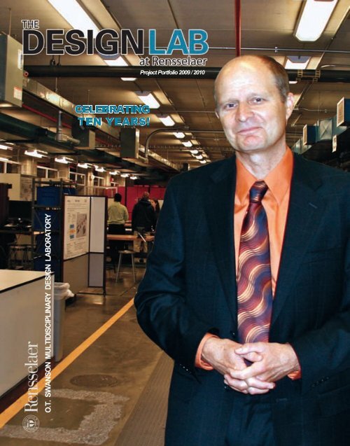
SCHOOL OF ENGINEERING<br />
O.T. SWANSON MULTIDISCIPLINARY DESIGN LABORATORY<br />
CELEBRATING<br />
TEN YEARS!<br />
Project Portfolio 2009 / 2010
Bob Swanson and Cynthia Shevlin visiting <strong>The</strong> <strong>Design</strong> <strong>Lab</strong><br />
happy to to see all the progress after 10 years.<br />
Photo credit: <strong>Rensselaer</strong> / Barry Stein
Copyright © 2010<br />
<strong>Rensselaer</strong> <strong>Polytechnic</strong> <strong>Institute</strong><br />
All rights reserved.<br />
No part of this publication may be<br />
reproduced, stored in a retrieval system<br />
or transmitted in any form by any means<br />
electronic, mechanical, photographic,<br />
recording or otherwise without<br />
written permission of the<br />
<strong>Rensselaer</strong> <strong>Polytechnic</strong> <strong>Institute</strong>.<br />
3<br />
5<br />
7<br />
8<br />
9<br />
10<br />
11<br />
13<br />
14<br />
15<br />
16<br />
17<br />
19<br />
21<br />
23<br />
25<br />
27<br />
29<br />
31<br />
33<br />
34<br />
35<br />
37<br />
39<br />
Contents<br />
Director’s Letter<br />
Balance Assist System - General Dynamics<br />
Smart Grid - GE<br />
Structural Wind Turbine Nacelle - GE<br />
Two Piece Wind Turbine Blade - GE<br />
Wind Turbine Interaction - GE<br />
WInd Turbine Tower Concepts - GE<br />
Quantity Sensor Redesign - Hamilton Sundstrand<br />
Parallel Processing for Radar Analysis - Lockheed Martin<br />
Bearing Life - DRS<br />
Camera Study<br />
Automatic Font Identification - Monotype Imaging<br />
Hybrid Actuator - Northrop Grumman<br />
Managing Information Overload - SAIC<br />
Senior Friendly Shopping Cart - Albany Guardian Society<br />
Biometrics - RPI<br />
<strong>Design</strong> for Sustainabiltiy - RPI<br />
Blind Assembly - NABA<br />
Balance Ball System - RPI<br />
Biomass Scope Study - KNUST<br />
Culturally Situated <strong>Design</strong> Tools - RPI<br />
Leopard Tracking - Stellenbosch<br />
<strong>The</strong> Staff and Faculty<br />
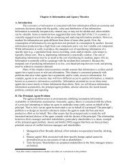
<strong>About</strong> <strong>The</strong> <strong>Design</strong> <strong>Lab</strong>
<strong>The</strong> entrance to <strong>The</strong> <strong>Design</strong> <strong>Lab</strong> where students meet<br />
with their project teams.<br />
Photo credit: <strong>Rensselaer</strong> / Barry Stein
Dear Friends:<br />
Thanks to a generous gift from Robert Swanson and his wife Cynthia Shevlin, the O.T. Swanson<br />
Multidisciplinary <strong>Design</strong> <strong>Lab</strong>oratory was built and opened its doors in the Spring of 2001 to a small<br />
cadre of students who participated in “real-world” industry sponsored projects. This year we<br />
celebrate our ten-year anniversary with this special inaugural issue of the <strong>Design</strong> <strong>Lab</strong> Projects<br />
Portfolio.<br />
Since its inception, the <strong>Design</strong> <strong>Lab</strong> has been a showcase facility for the School of Engineering.<br />
In the past ten years the <strong>Design</strong> <strong>Lab</strong> has successfully implemented an internationally recognized<br />
design program. Over 10,000 students have participated in project-based experiences since <strong>The</strong><br />
<strong>Design</strong> <strong>Lab</strong> was first opened. Every year over 600 sophomore level engineering students take<br />
Introduction to Engineering <strong>Design</strong> in the <strong>Design</strong> <strong>Lab</strong> in preparation for their senior level capstone<br />
design experience. Drawing upon <strong>Design</strong> <strong>Lab</strong> resources, students address some of the world’s<br />
major problems, while they learn about teamwork, communication and the design process.<br />
Over 400 senior-level engineering students from biomedical, computer systems, electrical, electric<br />
power, industrial, materials, and mechanical engineering work on multidisciplinary capstone design<br />
teams each year. <strong>The</strong> projects highlighted in the following pages show the results of our 2009-2010<br />
projects. As you review each project, I’m sure the level of effort, attention to detail, ingenuity, and<br />
overall quality of results from our students will impress you. Underlying the pages, which present<br />
the objectives, approach and results for each project, is the excitement and enthusiasm felt by each<br />
student as they eagerly engage in important projects with the support of our sponsors, faculty, and<br />
staff.<br />
Since its inception, we have conducted over 100 sponsored projects. We employ a team of full and<br />
part time faculty and staff who operate the lab and support our students. <strong>The</strong> <strong>Design</strong> <strong>Lab</strong> brings<br />
together a multitude of resources, programs, courses, curriculum, and people that have lead to<br />
<strong>Rensselaer</strong>’s recognition by Business Week magazine as one of the top 60 design schools in the<br />
world!<br />
As always thank you for your support and best wishes.<br />
Mark<br />
Mark Steiner<br />
Director, <strong>The</strong> <strong>Design</strong> <strong>Lab</strong>
4 <strong>The</strong> <strong>Design</strong> <strong>Lab</strong> at <strong>Rensselaer</strong><br />
Students on the Balance Assist team, perform a<br />
system calibration prior to a demonstration.
Purpose<br />
Current Balance System<br />
Medium Weight Shock Machine<br />
• Currently equipment is loaded and placed on balance<br />
stands<br />
• Load is adjusted manually until system appears<br />
balanced<br />
• Process is very time consuming<br />
5 <strong>The</strong> <strong>Design</strong> <strong>Lab</strong> at <strong>Rensselaer</strong><br />
Balance Assist System<br />
Team: Ron Carl (ELEC), James Edward Gryzbek (MECL), Matt LaBounty (MECL), Karl Meyer (MGTE), Graham Ostrander (MECL),<br />
Alex Peach (ELEC), John Petsche (MECL), Jonathan Proule (MGTE)<br />
Semester Objectives<br />
Deliver a system that:<br />
• Determines shock plate adjustments for one shot<br />
balance<br />
• Includes load measuring support stands compatible<br />
with MWST<br />
• Includes improved <strong>Lab</strong>VIEW program<br />
Project History<br />
Prototype <strong>Lab</strong>VIEW GUI<br />
• Developed proof of concept<br />
• <strong>Design</strong>ed and constructed initial prototype<br />
• <strong>Design</strong>ed <strong>Lab</strong>VIEW program to operate system<br />
• Wrote step by step operation manual<br />
Technical Results<br />
<strong>Design</strong>: Mechanical<br />
Plunger Balance Stand<br />
Electrical<br />
• NI USB-9239 – 4-channel, 24-bit Analog Input Module<br />
• Honeywell Model 3270 Load Cell<br />
• Requirements<br />
• 5,000 lb. load capacity<br />
• Maximum of 3 5 inches in diameter<br />
• At least 0.1% of full scale accuracy<br />
• Output in range of �5 volts<br />
DAQ Enclosure DAQ Load Cell<br />
Analysis<br />
• System concept proven via mock stands with digital<br />
scales and two categories of testing<br />
• Teeter-totter System � Use one scale to give<br />
baseline of compatibility<br />
• Four Scale Test � Use four scales as a proof of<br />
theory in reducing margin of error(and associated<br />
cycle time)<br />
• Repeated proof of concept with load cells to ensure<br />
quality of production and applicability of design<br />
Accomplishments<br />
Mechanical<br />
• Manufactured four balance stands for<br />
practical application that incorporate<br />
load cell technology<br />
<strong>Lab</strong>VIEW Software<br />
Project Engineer: Mark Anderson (<strong>The</strong> <strong>Design</strong> <strong>Lab</strong>), Chief Engineer: Richard Alben (Dept. of Mechanical, Aerospace & Nuclear Eng);<br />
Submarine Balancing Equipment<br />
It is necessary to test major pieces of equipment for<br />
placement on submarines for the ability to withstand shock.<br />
This equipment, weighing multiple tons, is placed on top of<br />
a shock test machine.<br />
Part of this setup involves balancing the equipment to be<br />
tested so that it does not damage itself, the machine or<br />
nearby personnel.<br />
<strong>The</strong> students developed a system of load cells to be placed<br />
at the machine and a <strong>Lab</strong>VIEW software package that<br />
reduced the time needed for this setup by up to 75% during<br />
the course of the semester.<br />
<strong>The</strong> Balance Assist team standing behind their load cell system.<br />
• New Features:<br />
• Visual Aids<br />
• Real time System Status<br />
Indicators<br />
• Automatic Suggested<br />
• Use of Counterweights<br />
• Simple GUI<br />
• Enables Quick and Easy<br />
Balance Procedure<br />
2010 Project Portfolio 5
6 <strong>The</strong> <strong>Design</strong> <strong>Lab</strong> at <strong>Rensselaer</strong><br />
GE student teams including Nacelle, 2-piece Blade, Tower<br />
re-design, their professors, project engineers and sponsor mentors.<br />
© General Electric Company. Used by permission.
Smart Grid - PHEV Impact Study<br />
Robin Lafayette(EPOW), Jia Ma(CSYS), Norma-Ester Medina(MGMT), Justin Metzger(ELEC), Sabrina Moore(EPOW), Sam Ostrow(EPOW), Hao Ruan(ELEC)<br />
Project History<br />
A plug-in hybrid electric vehicle (PHEV) automobile design<br />
contains:<br />
� Electric motor<br />
� Internal combustion engine w/ rechargeable batteries<br />
Purpose:<br />
�To observe and analyze the impact of PHEVs on<br />
the power grid<br />
�Research for future project application<br />
Current Semester Objective:<br />
�Build a simulation to identify the optimal load<br />
schedule for a transformer and the effect on<br />
the thermal properties.<br />
<strong>The</strong> PHEV is an electric vehicle with a<br />
� Gas-tank backup reducing the emissions<br />
<strong>The</strong> cost of electricity for PHEV<br />
� Estimated to be less than one quarter of the cost of fuel<br />
Technical Results (Load):<br />
�23.6% loaded 1.25x the transformers rated load<br />
�9.26% remained overloaded for 5 hours of more<br />
© General Electric Company. Used by permission.<br />
Some models of PHEVs can:<br />
� Travel up to 300 miles on a single charge<br />
� Be fully recharged in one night<br />
(Ex. Toyota Prius, Ford Escape, Chevy Volt, and Tesla)<br />
Technical Results (<strong>The</strong>rmal):<br />
�For most scenarios, top oil temperature doesn’t<br />
exceed normal range (120 degrees Celsius)<br />
Hourly Temperature (C)<br />
100<br />
90<br />
80<br />
70<br />
60<br />
50<br />
40<br />
Rated Load: 37.5kW January, Albany NY<br />
Project Engineer: Mark Anderson (<strong>The</strong> <strong>Design</strong> <strong>Lab</strong>), Chief Engineer: Cheng Hsu (Dept. of Industrial & Systems Eng.)<br />
Power Distribution Systems<br />
As electric cars and hybrid vehicles are adopted by<br />
consumers, they will impact the power distribution systems.<br />
Based on consumer patterns, this will likely create different<br />
and varying electric loading scenarios<br />
that must be accounted for.<br />
<strong>The</strong> student team successfully developed a simulation tool to<br />
help model these variations.<br />
Accomplishments:<br />
�Load schedule optimization tool built using excel<br />
�User interface constructed using <strong>Lab</strong>VIEW<br />
�Output screens for thermal calculations using<br />
<strong>Lab</strong>VIEW<br />
With this tool set, the user can better understand how these<br />
loads may impact the grid at the neighborhood level and can<br />
thus plan accordingly.<br />
30<br />
20<br />
10<br />
0<br />
1 2 3 4 5 6 7 8 9 10 11 12 3 14 15 16 17 18 9 20 21 22 23 4<br />
© General Electric Company. Used by permission.<br />
Average<br />
Max<br />
Min<br />
Next Steps:<br />
�<strong>The</strong>oretical<br />
•Reduction of modeling assumptions to<br />
improve realism<br />
•Expansion of modeling area<br />
•Better VI to model simulation could be<br />
utilized<br />
�Practical<br />
•Physical representation of model<br />
•Improved communication between<br />
utilities, dealerships and vehicle owners<br />
•Modify HMI to include PHEVs<br />
2010 Project Portfolio 7
Present Nacelle Showing Bedplatemounted<br />
Gearbox, Shaft, generator and<br />
Yaw Bearing Surrounded by a<br />
Composite shell<br />
Project Scope<br />
1. Develop Structural Nacelle concepts<br />
•will allow direct mounting of a<br />
Wind Turbine Drive Train<br />
Components (Gearbox, Shaft,<br />
Bearing, generator, Yaw Bearing)<br />
•Provide protection, and allow<br />
maintenance, resist wind loads<br />
2. Down-select 2-3 concepts<br />
3. Develop CAD Models for selected<br />
concepts and Baseline (Bedplate<br />
type design)<br />
4. Develop Structural analysis models<br />
5. Perform structural analysis (static)<br />
6. Develop <strong>Design</strong> Trade-Off curves in<br />
design space<br />
Baseline Loading Model<br />
Wind Turbine <strong>Design</strong><br />
8 <strong>The</strong> <strong>Design</strong> <strong>Lab</strong> at <strong>Rensselaer</strong><br />
Dean Baker (MECL), Kaitlyn Calaluca (MS&E), Rima Deveikyte (MECL), Betsy Green (MECL, Bryant Johnson (MECL),<br />
Julienne <strong>Lab</strong>recque (MS&E), Robert Middleton (MS&E), Ethan Rudolph (MECL), Philip Scangas (MECL), Oliver Williams (MECL)<br />
Space Frame <strong>Design</strong> II<br />
1. 3.<br />
53,000 kg<br />
2.<br />
29,900 kg<br />
22,900 kg<br />
14,900 kg<br />
Bedplate Improvements<br />
Space Frame <strong>Design</strong> I<br />
4.<br />
Benefits:<br />
• Even stress distribution<br />
• Low principal stresses<br />
• High Stiffness<br />
• Low weight<br />
Network <strong>Design</strong><br />
Monocoque (Unibody) <strong>Design</strong><br />
© General Electric Company. Used by permission.<br />
Drawbacks:<br />
• Manufacturability<br />
• Weld construction<br />
• Ball joints<br />
• Requires a skin<br />
Ribbed monocoque design<br />
Corrugated sandwich structure<br />
Results from panel testing<br />
CTQs: Critical to Quality<br />
Stress<br />
Stiffness<br />
Weight/Cost<br />
Vibration<br />
Fatigue<br />
Transportability<br />
Manufacturability<br />
Maintainability<br />
Project Engineer: Scott Miller(<strong>The</strong> <strong>Design</strong> <strong>Lab</strong>), Chief Engineer: Richard Alben (Dept. of Mechanical, Aerospace & Nuclear Eng)<br />
A wind turbine nacelle is typically an environmental cover<br />
protecting the subsystems within the wind turbine machine<br />
head. <strong>The</strong> machine head is the bus-sized structure that sits<br />
on top of the wind turbine tower.<br />
It supports the turbine rotor and power transmission and<br />
generation components such as the rotor shaft, gearbox,<br />
coupling, generator, and bearings. <strong>The</strong> machine head<br />
internal components are mounted on a massive metal<br />
bedplate, which also holds the composite material nacelle.<br />
<strong>The</strong> goal was to provide quantitative information on novel<br />
nacelle design concepts to help the customer decide whether<br />
to launch a commercialization effort.<br />
To this end, GE asked the team to tap a diverse range of<br />
mechanical design concepts and fabrication techniques<br />
from other industries, while applying wind specific design<br />
constraints.<br />
<strong>The</strong> GE 4.0-110 turbine<br />
• Able to sustain weight of<br />
generator, gearbox, and rotor<br />
• Able to distribute stress<br />
throughout nacelle<br />
• Maximum deflection of the<br />
shaft is<br />
• 0-1 degrees<br />
• Optimized for minimum<br />
weight through FEA<br />
• Effects from machinery, yaw<br />
bearing, nacelle due to winds<br />
• Able to withstand cyclic<br />
loading<br />
• Assess the effects of crack<br />
propagation<br />
• Define a process of<br />
transportation<br />
• Define a process of<br />
manufacturing<br />
• Able to access interior of<br />
nacelle<br />
Performance Criteria<br />
<strong>The</strong> nacelle should deflect less than 1 degree<br />
at the tip of the shaft (35 mm)<br />
Next Semester Plans<br />
• Fatigue and Vibration analysis<br />
• Honeycomb sandwich structure research<br />
and analysis<br />
• Application of sandwich structures to<br />
optimize weight reduction and strength<br />
• Exploration of modified spaceframe<br />
options<br />
• Research on spaceframe shell thickness<br />
• Continuation of network design<br />
© General Electric Company. Used by permission.
Project Goal<br />
<strong>Design</strong> a one of two feasible junctions for a<br />
two piece 50+ meter wind turbine blade<br />
Junction Criteria<br />
1. Transfer all loads on blade in such a way<br />
that failure is predicted to occur outside<br />
of junction area before junction fails<br />
2. Maintain current performance by<br />
minimizing weight addition and<br />
additional drag<br />
3. Additional manufacturing costs must be<br />
justifiable by transportation and<br />
assembly cost savings<br />
Governing Physics<br />
For bolt and adhesive analysis<br />
Bolt Thread shear stress<br />
Bolt Tensile stress<br />
Bolt shear stress<br />
Adhesive shear stress<br />
Adhesive peel strength<br />
t<br />
t<br />
Pos t on 1<br />
Loca ion # Loca ion # Lo at on # Loc on #<br />
1 2 3 4<br />
cr cal end ng 6 3 0 46 0 0<br />
m d po nt b nding 0 26 4 2 0 26 4 2<br />
ax al 13 8 13 8 13 8 13 8<br />
pre oad 17 6 17 6 17 6 17 6<br />
jo nt c nt ipe al 0 11 0 11 0 11 0 1<br />
Total 38 07 36 17 31 77 35 71<br />
Green Energy Initiatives<br />
Two-Piece Wind Turbine Blade<br />
Jeremy Crouse, (MECL) Jonathan White (MECL), Colin Danek (MECL), Rob Houliston (MS&E), Tricia Kent (MS&E),<br />
Alex Robb (MECL), Charlie Russo (MECL), David Kozak (MECL), Andrew Abrew (MS&E), Manny Lavin (MECL)<br />
S ess MPa<br />
Model Development-CAD/FEA<br />
Worm Screw Bolt<br />
Physical Testing<br />
Using Instron Machine<br />
2 5<br />
2<br />
1 5<br />
1<br />
0 5<br />
0<br />
0 5<br />
0 35<br />
0 3<br />
0 25<br />
0 2<br />
0 15<br />
0 1<br />
0 05<br />
0<br />
0<br />
Bo t Material Dens ty vs UTS<br />
S ress vs St a n or Var ous Prototypes<br />
0 05 0 1 0 5 0 2 0 25 0 3 0 35<br />
Stra n (mm)<br />
A hes ve on Bu t J in in She r<br />
A hes ve on Dov ta l o nt n T ns on<br />
B l ed Lap n Shear<br />
A hes ve on Bu t J in in Ten i n<br />
Do e ai Shear<br />
Do e ai Shea 2<br />
A hes ve She r<br />
A hes ve She r 2<br />
B l But Jo nt<br />
Wo msc ew en ion<br />
C-Channel adhesive<br />
w/square dovetails<br />
© General Electric Company. Used by permission.<br />
C-Channel adhesive<br />
w/angled dovetails<br />
Project Engineer: Casey Goodwin (<strong>The</strong> <strong>Design</strong> <strong>Lab</strong>), Chief Engineer: Gregory Hampson (Dept. of Mechanical, Aerospace & Nuclear Eng)<br />
<strong>The</strong> GE Wind Energy business was created as a result<br />
of the Ecomagination and Green Energy initiatives at GE<br />
Energy. GE currently has over 12,000 1.5MW wind turbines<br />
in operation worldwide. <strong>The</strong> next generation machine, the<br />
GE 2.5MW product is expected to grow substantially in<br />
market share. GE is continuously striving for creative ways<br />
to design, update, or redesign components for improved<br />
performance and low cost, and delivers customer value via<br />
a cost effective product that meets or exceeds requirements.<br />
Longer wind blades are able to capture more of the wind’s<br />
energy than shorter ones. However, large blades are very<br />
difficult to transport. Two-piece blade designs, with the<br />
ability to assemble them in two halfs in the field would<br />
address this problem. However, the biggest challenge is<br />
to have a junction design that is structurally robust and<br />
aerodynamically equivalent to a pristine “un-jointed”, single<br />
piece blade.<br />
t in<br />
© General Electric Company. Used by permission.<br />
St a n<br />
St e s (k a)<br />
C-Channel + adhesive<br />
Overlap Length<br />
25 0<br />
0 000 5<br />
0 0004<br />
20 0<br />
0 000 5<br />
0 0003<br />
15 0<br />
0 000 5<br />
0 0002<br />
10 0<br />
0 000 5<br />
5 0<br />
0 0001<br />
0 000 5<br />
0<br />
0<br />
0 0 5 1 1 5 2 2 5<br />
eng h (m)<br />
Bolts in Shear Dovetail Adhesive Shear Adhesive Bolts in Tension<br />
*Physical Testing was used to confirm results of calculations<br />
and Finite element analysis<br />
St ain<br />
M x Von M es<br />
St e s X<br />
St e s Y<br />
St e s Z<br />
2010 Project Portfolio 9
Analysis Assumptions<br />
•All towers are assumed to be 100m tall<br />
unless otherwise specified<br />
•Drag force from wind has been simplified to<br />
drag on three flat surfaces with the width and<br />
length of the blades<br />
•No moment due to Nacelle and blades<br />
•Yield Strength of steel 250 Mpa<br />
•No torsional load<br />
•Specific cost of steel $3.3/kg<br />
•Steel Density 7800kg/m 3<br />
Cost ($x1,000,000)<br />
400<br />
350<br />
300<br />
250<br />
200<br />
150<br />
100<br />
50<br />
0<br />
Stress (MPa)<br />
$1.60<br />
$1.40<br />
$1.20<br />
$1.00<br />
$0.80<br />
$0.60<br />
$0.40<br />
$0.20<br />
$0.00<br />
Modular Panel <strong>Design</strong><br />
•Friction connections (bolts and plates) instead of welds<br />
•Material savings after eliminating ring flanges<br />
•Cutting of plates may be less expensive than welding<br />
Structural:<br />
•Main Metric is Total Stress<br />
•Unless specified otherwise tower height is 100m<br />
•Total= Bending Stress Axial Stress<br />
•Modeled as:<br />
• Hollow steel cylinder<br />
• Constant diameter<br />
• Constant wall thickness<br />
•Main factors are wall thickness and height<br />
•Torsion and fatigue not considered in initial analysis<br />
Cost<br />
•Mass connection plates and bolts neglected<br />
Total Stress vs. Height<br />
(Diameter =3.5m, Wind Speed = 20m/s)<br />
Steel Y eld St ength<br />
80 90 100 110 120<br />
Height (m)<br />
Cost vs. Wall Thickness<br />
(H=100m, D=3.5m, Wind Speed=20m/s)<br />
Kyle Allen (MECL), Drew Shamyer (MECL), Alex Gage (MS&E), Brian Severino (MECL), CJ Vincent )(MECL),<br />
.025m Wall<br />
Th ckness<br />
.030m Wall<br />
Th ckness<br />
.035m Wall<br />
Th ckness<br />
.040m Wall<br />
Th ckness<br />
.045m Wall<br />
Th ckness<br />
0.020 0.025 0.030 0 035 0.040 0.045 0.050<br />
Wa l Thickness (m)<br />
Tower of Power<br />
Michael Hughes (MECL), Tyler Scully (MECL), John Vinueza (MECL)<br />
Total Stress vs. Wind Speed<br />
450<br />
400<br />
Semimonocoq<br />
350<br />
300<br />
250<br />
ue Stress<br />
Lattice w/ Skin<br />
Stress<br />
Modular Pane Steel Yield Strength<br />
200<br />
Stress<br />
Hybrid Base<br />
150 Stress<br />
I Beam Lattice<br />
100<br />
50<br />
0<br />
Stress<br />
0 10 20<br />
Wind Speed (m/s)<br />
30<br />
Stress (MPa)<br />
Stress (MPa)<br />
Cost ($x1,000,000)<br />
120<br />
100<br />
80<br />
60<br />
40<br />
Lattice With Skin<br />
Structural<br />
•Modeled as:<br />
• 4 posts with .5” thick skin (skin<br />
does not support bending<br />
loads)<br />
• Tower length and width held<br />
constant as the dimensions at<br />
the center of pressure<br />
• Bending moment calculated<br />
using drag on blades as well as<br />
tower<br />
Cost<br />
•Lattice neglected in cost model<br />
Total Stress vs. Height<br />
Base W dth 7m<br />
Base W dth 10m<br />
Base W dth 13m<br />
80 100 120<br />
Height (m)<br />
4<br />
3 5<br />
3<br />
2 5<br />
2<br />
1 5<br />
1<br />
0 5<br />
0<br />
Cost vs. Base Width<br />
5 6 7 8 9 10 11 12 13<br />
Base Width (m)<br />
© General Electric Company. Used by permission.<br />
Semi-Monocoque<br />
Wind Speed vs. Maximum Stress in a<br />
Structural<br />
467<br />
4m Diameter Tower<br />
0.700<br />
Number of Beams vs. Cost<br />
•Properties of W14x99 I-Beam<br />
used<br />
•Modeled as:<br />
•Vertical I – Beams Only<br />
•Beams evenly spaced apart<br />
•Beams centroids placed at radius<br />
of tower<br />
417<br />
367<br />
317<br />
267<br />
217<br />
167<br />
117<br />
67<br />
Steel Y eld St ength<br />
0.600<br />
0.500<br />
0.400<br />
0.300<br />
0.200<br />
0.100<br />
17<br />
0.000<br />
Cost<br />
0 10 20 30<br />
0 5 10 15 20<br />
•Mass of stab lization rings and<br />
Wind Speed (m/s)<br />
Number of Beams<br />
bolts neglected<br />
15 Beam Towe 12 Beam Towe 10 Beam Towe<br />
I-Beam Lattice<br />
Structural:<br />
•Modeled as four vertical I-beams with skin<br />
around it<br />
•Effects of lattice connection plates and<br />
taper neglected<br />
• Properties of W27x178 I-Beams used<br />
unless specified otherwise<br />
Cost:<br />
•<strong>The</strong> lattice the connection plates and<br />
taper were neglected for cost analysis<br />
•Skin material was assumed to be steel<br />
Hybrid Base<br />
Structural<br />
•Modeled as:<br />
•Cylindrical tower of only<br />
concrete<br />
•Induced stresses assumed to<br />
be the same as a 00m tall<br />
concrete tower<br />
Cost<br />
•Modeled as:<br />
•Cylindrical tower of concrete<br />
with 1’’ thick steel shell<br />
Some towers are 30 feet in diameter in order to support the machine head, rotor and blades.<br />
10 <strong>The</strong> <strong>Design</strong> <strong>Lab</strong> at <strong>Rensselaer</strong> © General Electric Company. Used by permission.<br />
Stress (MPa)<br />
8 Beam Towe 6 Beam Towe<br />
Project Engineer: Casey Goodwin (<strong>The</strong> <strong>Design</strong> <strong>Lab</strong>), Chief Engineer: Daniel Lewis (Dept. of Materials Science & Eng.)<br />
<strong>The</strong> tower of a wind turbine carries the Machine Head and<br />
the Rotor plus the Blade. Typically, large wind turbines utilize<br />
tubular steel towers, lattice towers, or concrete towers.<br />
Guyed tubular towers are only used for small wind turbines.<br />
More recently, we see Hybrid Towers in use. Each has its<br />
advantages and drawbacks.<br />
All towers are required to function under random wind<br />
loading (fatigue). <strong>The</strong>y are also required to survive under<br />
what is known as “Fifty Year Gust Loads”.<br />
<strong>The</strong> team proposed a solution to meet the needs of fatigue,<br />
life, strength, stiffness, natural frequency, buckling and other<br />
requirements.<br />
Stress (MPa)<br />
Cost($x1,000,000)<br />
300<br />
250<br />
200<br />
150<br />
100<br />
50<br />
0<br />
$0.00<br />
Total Stress vs. Tower Height<br />
(t=0.25in, D=4m, Wind Speed=20m/s)<br />
50 60 70 80 90 100 110 120 130 140 150<br />
Tower He ght (m)<br />
Cost vs. Height<br />
(D=4m)<br />
50 75 100 125 150<br />
Tower Height (m)<br />
t=.125 n<br />
t=.25 n<br />
t=.5 n<br />
70<br />
60<br />
50<br />
40<br />
30<br />
20<br />
10<br />
0<br />
Stress (MPa)<br />
Cost ($x1,000)<br />
160<br />
140<br />
120<br />
100<br />
80<br />
60<br />
40<br />
20<br />
0<br />
Cost ($x1,000,000)<br />
•Concrete estimated to cost $2.78 per ft 3<br />
and 2400kg/m 3<br />
•Cold rolled steel is estimated to cost<br />
$1.5 per lb (Albany Steel)<br />
Bending Stress vs. Wall Thickness<br />
0 0.5 1 1.5 2 2.5 3<br />
Wall Thickness (m)<br />
Cost vs. Wall Thickness<br />
0 0.5 1 1.5 2 2.5<br />
Wall Thickness (m)
Vision and Scope<br />
Develop models for the interaction of wind turbines to improve<br />
spacing and operational strategies to maximize power generated<br />
from wind farms. <strong>The</strong>se models will strengthen GE s position as a<br />
supplier of wind turbine equipment and wind farm design services.<br />
GE Wind Turbine Interaction<br />
Kyle Barden (MECL), Alex Field (MGMT), Chris Fiore (MECL), Chris Jones (MECL), Erik Jurgensen (MECL), Hyunkyu Kim (ELEC), Steve Knapp (MECL), Alec Marshall (MECL), Philip Reed (MECL)<br />
© General Electric Company. Used by permission.<br />
Current Objectives<br />
1. Implement improved Cp and higher TSR rotor designs supplied by GE.<br />
2. Characterize the performance of the improved model wind turbines in the<br />
wind tunnel. Variables tested will be wind speed, TSR, and yaw angle to measure<br />
thrust and wake profiles.<br />
3. Implement visualization techniques to better understand and analyze wake<br />
effects.<br />
Tower System Improvements<br />
Results<br />
Rotor <strong>Design</strong>s and Manufacturing<br />
Old Tower New Tower<br />
•Ability to check motor<br />
overheating<br />
•Redundant thrust<br />
readings<br />
•Better signal<br />
processing<br />
New Nacelle<br />
•Enabled thrust<br />
measurement<br />
•Better aerodynamics<br />
•Stronger nacelle<br />
Code Modifications<br />
Old Interface<br />
Circuitry Upgrades<br />
•No voltage interaction<br />
between dynos<br />
•Increased power<br />
capacity<br />
•Higher tolerance<br />
resistors<br />
•Individual power<br />
supplies<br />
•Modular face plates<br />
New Interface<br />
��<br />
Wind Tunnel Set Set-up up<br />
� �<br />
� �<br />
� �<br />
� �<br />
�� �<br />
�� �<br />
������ ���������� ���� ����� ������� ����<br />
�� �<br />
�� �� �� � �<br />
���<br />
� �<br />
Faulhaber 1331<br />
Faulhaber Faulhaber 2232<br />
GWS RS-385SH RS 385SH<br />
�<br />
�<br />
�<br />
�<br />
�<br />
� � �<br />
�<br />
�<br />
Fall ‘09 Rotor<br />
Dynamometer Selection<br />
GE <strong>Design</strong>ed Rotor, ABS<br />
Team <strong>Design</strong>ed Rotor GE <strong>Design</strong>ed Rotor, SLA Material Deflection Comparison<br />
•Higher RPM motors<br />
•Higher current motors<br />
Old Circuitry New Circuitry<br />
Project Engineer: Scott Miller (Core Engineering), Chief Engineer: Richard Alben (Dept. of Mechanical, Aerospace & Nuclear Eng)<br />
Improving Wind Farms<br />
��<br />
���<br />
���<br />
���<br />
���<br />
����<br />
����<br />
����<br />
����<br />
����<br />
��� ����� �� ��� �������� ������ �������<br />
Wind turbines are typically clustered in “wind farms” of 5 to<br />
more than 100 machines. It is desirable to space the turbines<br />
widely enough apart that the available wind energy for each<br />
turbine is only slightly reduced by the action of other turbines<br />
in the wind farm. But widely spaced turbines mean less power<br />
for a given land area. <strong>The</strong>se interactions include both wake<br />
effects from up-wind turbines and also up-flow disturbances<br />
from down-wind turbines.<br />
<strong>The</strong> goal of this project was to develop an improved<br />
understanding of these interactions and, in partiticular,<br />
determine if the overall system performance of the wind farm<br />
can be improved by accounting for the interactions, instead<br />
of just trying to optimize each turbine individually.<br />
GE asked us to study the effects of interaction for other rotors,<br />
especially some with higher efficiencies, and also study the<br />
physical and data acquisition enhancements to our system.<br />
����<br />
� �<br />
���<br />
���<br />
���<br />
�<br />
�<br />
�<br />
�<br />
4-bladed rotor<br />
•Smoke visualization capable<br />
•Blade end effects/Axial induction<br />
factor<br />
•Reduced angular velocity<br />
•<strong>The</strong>oretical higher Cp<br />
Flow Visualization Techniques<br />
Fall ‘09 Results<br />
New Smoke<br />
•Experimenting with<br />
Visualization<br />
more effective<br />
visualization techniques<br />
GE rotor<br />
•<strong>The</strong>oretical higher Cp/TSR<br />
Each wind turbine has an effect on the ones next to it or behind it.<br />
© General Electric Company. Used by permission.
12 <strong>The</strong> <strong>Design</strong> <strong>Lab</strong> at <strong>Rensselaer</strong><br />
Students on the Hamilton Sundstrand team presenting designs<br />
for measuring the volume inside devices within a space station.
Measuring Volume In Outer Space<br />
Quantity Sensor Redesign<br />
Craig Eaton (MS&E), Burton Francis (MECL), Richard Grebe (MECL), Adam Jankauskus (ELEC), Lukas Leinhard (MECL),<br />
Jeffery Musante (ELEC), Arvind Ramachandran (MS&E), Michelle Santospirito (MGMT)<br />
Background Information<br />
<strong>The</strong> Hamilton Sundstrand Bellows Accumulator is a tank used for storing liquid in<br />
aerospace life support systems applications. Inside the accumulator, a quantity<br />
sensor determines the volume of the liquid present by measuring the<br />
displacement of the bellows. <strong>The</strong> current device, a string potentiometer, fails too<br />
frequently because of launch vibrations. A new measurement device is needed.<br />
Measurement Results<br />
Figure 1 shows a simulation of<br />
ideal experimental output.<br />
Figures 2 and 3 show actual laser<br />
and ultrasonic measurements,<br />
respectively. Note that the laser<br />
most closely resembles the ideal<br />
system.<br />
Figure 1 Figure 2<br />
Figure 3<br />
Systems that are used in space applications must be<br />
stable and reliable while deployed for up to 30 years. It is<br />
necessary to measure the volume of fluid in the various<br />
systems on the space station platforms.<br />
For approximately ten years the sponsor had been<br />
considering various technologies but had not selected an<br />
alternative.<br />
One student team successfully identified promising<br />
technologies that could be used to replace the current<br />
measurement technology. <strong>The</strong> second student team then<br />
found workable and readily available hardware for two of<br />
the potential technologies and performed a gage reliability<br />
and repeatability analysis on a prototype system they<br />
designed and constructed. As a result, they were able to<br />
prove that both selected technologies were viable for the<br />
application.<br />
Loop Fluid<br />
(Water, Urine,<br />
Coolant)<br />
Results:<br />
• <strong>The</strong> laser is a more precise measuring device.<br />
• <strong>The</strong> ultrasonic sensor is a more accurate, robust, and reliable measurement system.<br />
• Both sensors work in the system and greatly surpass the sponsor’s standards in terms of<br />
percent error of full scale.<br />
Recommendations:<br />
• Hamilton should re-evaluate their error standards.<br />
• <strong>The</strong> sponsor should choose laser for immediate use and precision.<br />
• <strong>The</strong> sponsor should choose ultrasonic and research a calibration method for a more<br />
accurate and reliable measurement system.<br />
Hamilton Sundstrand Bellows Accumulator<br />
Bellows<br />
Gas Charge<br />
(Air, Nitrogen,<br />
Helium)<br />
Our Working Prototype<br />
(a.) 4” x 48” hydraulic cylinder<br />
(a.) 3/8” threaded rod<br />
(b.) Ruler mounted to piston<br />
(c.) 3/8” threaded rod actuation of piston driven by<br />
power drill<br />
(d.) Cylinder mounted on 80 x 20 struts<br />
(e.) Sensors mounted directly to cylinder, radially<br />
constrained by cap fitted in cylinder bore<br />
(f.) Spring braces used to consistently reproduce holding<br />
pressure of sensor caps to cylinder<br />
Project Objectives:<br />
1) Create a working prototype of a<br />
Hamilton Sundstrand Bellows<br />
Accumulator.<br />
2) Test the performance of laser and<br />
ultrasonic distance sensors in the<br />
accumulator for use as a<br />
replacement for their current<br />
sensor.<br />
3) Decide which technology best<br />
suits the sponsor’s needs and<br />
recommend which technology to<br />
move forward with.<br />
(b.) Power drill attachment position<br />
(c.) Socket ratchet attachment position<br />
(d.) Intermediate block connecting<br />
linear actuator to piston<br />
Project Engineer: Mark Anderson (<strong>The</strong> <strong>Design</strong> <strong>Lab</strong>), Chief Engineer: Daniel Lewis (Dept. of Materials Science & Eng.)<br />
Students meeting with the mentors at Hamilton Sundstrand.<br />
2010 Project Portfolio 13
14 <strong>The</strong> <strong>Design</strong> <strong>Lab</strong> at <strong>Rensselaer</strong><br />
Parallel Processing for Radar Analysis<br />
Team: Eric Allen (CSYS), Bryan Bessen (ELEC), Daniel Branken (CSYS), Jonathan Jesuraj (CSYS), Matthew Kloepfer (ELEC),<br />
Jonathan Marini (CSYS), Alexandru Radocea (CSYS), Joseph Sgarlata (ELEC), Daniel Sullivan (ELEC), Brandon <strong>The</strong>tford (CSYS)<br />
Project Purpose: Determine how different methods of processing radar signals can speed up the analysis and performance of a radar system algorithm provided by Lockheed Martin.<br />
This has been explored by comparing results of single and multiple Graphical Processing Units (GPUs) against a Central Processing Unit (CPU) implementation.<br />
Technical Requirements:<br />
•Examine average run times versus<br />
number of objects in scene<br />
•Determine average runtime versus<br />
CPU/ GPU resources<br />
Radar Algorithm:<br />
W(f) RCS(f)<br />
s(t ) S(f) HMF(f) scp(t) fft() conj() ifft() ifftshift()<br />
H<br />
S(f)<br />
MF(f) • W(f) • RCS(f)<br />
Provided Algorithm<br />
Simulink Model of Algorithm<br />
System Inputs and Output:<br />
Amp ude<br />
Amp de<br />
2<br />
1 5<br />
1<br />
0 5<br />
0<br />
-0 5<br />
1<br />
-1 5<br />
2<br />
0 50 100 50 00 2 0 3 0 3 0 400 450 500<br />
1 5<br />
1<br />
0 5<br />
0<br />
-0 5<br />
( )<br />
T me s)<br />
Fr quecny<br />
Input Chirp Signal s(t) W(f) Filter<br />
RCS ) Noi e<br />
1<br />
0 0 5 1 1 5 2 2 5 3 3 5<br />
Fr quecny<br />
x 10<br />
Radar Cross Section, RCS(f)<br />
4<br />
0 0 5 1 1 5 2 2 5 3 3 5<br />
x 10 4<br />
W f) F ter<br />
1<br />
0 9<br />
0 8<br />
0 7<br />
0 6<br />
0 5<br />
0 4<br />
0 3<br />
0 2<br />
0 1<br />
0<br />
Amp ude<br />
Amp de<br />
4<br />
x 10<br />
6<br />
5<br />
4<br />
3<br />
2<br />
1<br />
Sc ( )<br />
0 0 5 1 1 5 2 2 5 3 3 5<br />
x 10 4<br />
0<br />
T me s)<br />
Output Signal Scp(t) How a GPU Splits Up Work<br />
Doing the parallel calculation<br />
V1 VR = V1 * V2<br />
V2 1 2 3 4 . . .<br />
1 2 3 4 . . .<br />
V R [1] = V1[1] * V2[ ]<br />
Returns Per Second<br />
2 500<br />
2 000<br />
1 500<br />
1 000<br />
500<br />
0<br />
7,000<br />
6,000<br />
5,000<br />
4,000<br />
3,000<br />
2,000<br />
1,000<br />
0<br />
*<br />
*<br />
*<br />
*<br />
*<br />
*<br />
1 2 3 4 . . .<br />
VR *<br />
*<br />
*<br />
*<br />
*<br />
*<br />
V R [4] = V1[4] * V2[4]<br />
GPU P ocesso<br />
GPU vs. mGPU vs. CPU - Returns Per Second<br />
8,000<br />
GPU - 16K<br />
GPU - 32K<br />
GPU - 64K<br />
mGPU - 16K<br />
mGPU - 32K<br />
mGPU - 64K<br />
CPU - 16K<br />
CPU - 32K<br />
CPU - 64K<br />
y = 16.002ln(x) 207.8<br />
R² = 0.989<br />
512 4 096 32,768 262,144 2,097 152<br />
Number of Elements (log8 scale)<br />
1 8 64 512 4,096 32,768<br />
Number of Returns Processed<br />
Radar System Performance Improvement<br />
Loops X/N<br />
returns until<br />
processed<br />
<strong>Design</strong><br />
Splitting Work Between Multiple GPUs<br />
X RCS(f)’s on CPU<br />
X/N Returns X/N Returns X/N Returns<br />
GPU 1 GPU 2 . . . GPU N<br />
X S cp(t)’s on CPU<br />
Each GPU is responsible for an equal number of returns and they all perform<br />
calculations in parallel to each other and return the results to the CPU.<br />
Technical Results<br />
Project Engineer: Mark Anderson (<strong>The</strong> <strong>Design</strong> <strong>Lab</strong>) , Chief Engineer Junichi Kanai (Dept. of Electrical, Computer, & Systems Eng.)<br />
In the design of radar systems it is important to accurately<br />
model and simulate various conditions. Modern radar<br />
systems utilize computers to analyze the received signals.<br />
Simulation testing is an extremely computer intensive effort<br />
and requires significant time investment, thus reducing<br />
both the fidelity and the quantity of analysis that can be<br />
performed.<br />
<strong>The</strong> student team was able to study the algorithms used<br />
and re-implement them using the processing power found<br />
in a typical graphics card (GPU).<br />
<strong>The</strong> students were able to offer performance improvements<br />
of 2-3 times for some cases and much more overall – using<br />
a $100 PC card!<br />
Time (ms)<br />
Vector Size vs. Time for CPU vs. GPU GPU vs. mGPU vs. CPU - Time per Return<br />
GPU - 16K<br />
GPU - 32K<br />
GPU<br />
GPU - 64K<br />
mGPU - 16K<br />
CPU<br />
3,500<br />
mGPU - 32K<br />
Log F t (GPU)<br />
y = 195 44x0 1618<br />
R² 0 9789<br />
3,000<br />
mGPU - 64K<br />
CPU - 16K<br />
Powe F t (CPU)<br />
CPU - 32K<br />
2,500<br />
CPU - 64K<br />
Time (µsec)<br />
1,000,000<br />
Time (ms)<br />
2,000<br />
1,500<br />
1,000<br />
500<br />
0<br />
100,000<br />
10,000<br />
1,000<br />
100<br />
10<br />
[ Whe e mGPU mu t ple GPUs ( n this c se 2 GPU ) ]<br />
1<br />
1 8 64 512 4 096 32,768<br />
Number of Returns Processed<br />
GPU vs. mGPU vs. CPU - Returns vs. Time<br />
GPU - 64K<br />
mGPU 16K<br />
mGPU - 32K<br />
mGPU 64K<br />
CPU - 1 K<br />
CPU - 32K<br />
CPU - 6 K<br />
1 4 16 64 256 1,024 4 096<br />
Number of Returns Processed<br />
Time �<br />
How Our Algorithm is Processed<br />
CPU<br />
GPU<br />
Allocate Memory and<br />
copy Data for RCS(f)’s<br />
Limited by CPU RAM size<br />
→ s(t) and W(f) data transfer to GPU →<br />
FFT on s(t)<br />
S(f) x S*(f) x W(f)<br />
→ RCS(f) data transfer to GPU →<br />
Loop until all Multiply RCS(f)’s * HMF(f) returns are<br />
processed IFFT on Scp(f)’s and shift<br />
← Scp(t) data transfer to CPU ←<br />
Return Scp(t)’s Pre-computed<br />
to save time<br />
Return to CPU<br />
when no more<br />
RCS(f)’s<br />
Semester Objectives Met:<br />
•Generation of universal test data<br />
•Agreement among multiple models of<br />
radar systems<br />
•Detailed timing and performance<br />
analysis<br />
•Accuracy analysis<br />
Conclusion:<br />
•Use of GPUs increases throughput by<br />
2-6 times over our CPU implementation<br />
•Algorithm easily parallelized on GPU<br />
•Scales linearly across two GPUs<br />
Next Steps:<br />
•Summation of RCS before signal chain<br />
to improve runtime<br />
•Address potential RCS input bottlenecks<br />
to keep up with GPU processing<br />
•Evaluate effects of different GPUs on<br />
performance<br />
Lockheed Martin team standing in front of their poster inside <strong>The</strong> <strong>Design</strong> <strong>Lab</strong>.
Effects of Stray Currents on Bearing Life<br />
Lun Chen (ELEC), Dan Frydryk (MS&E), Colin Haynes (MS&E), Nodari Ivanov (MECL),<br />
Seth Jones (ELEC), Jason Livingston (MECL), Bryan Scala (MGMT), Josh Smolensky (MECL), John Velonis (ELEC)<br />
Purpose Test Capability<br />
<strong>Design</strong>, construct, and deliver an<br />
apparatus which will test and analyze the<br />
effects of stray currents on bearing life.<br />
Technical <strong>Design</strong> Approach<br />
• Parallel processing<br />
• Communica^on<br />
• Redundancy<br />
• Keep It Simple<br />
Transforma^on of <strong>Design</strong><br />
Instrumenta^on<br />
• Max Load: 0-‐950 at 150psi<br />
• Voltage Range: 0-‐30v<br />
• Amperage: 0-‐10A<br />
• Signal Frequency: 60-‐10,000Hz<br />
• Rota^on Speed: 2000 rpm variable<br />
drive<br />
System Features<br />
• Safe opera^on with cau^on labels<br />
• Custom <strong>Lab</strong>view UI with controls<br />
• Easy to assemble 8020 base<br />
• Plug and play measurement<br />
devices<br />
• Removable collar for easy access<br />
• Con^nuous variable drive<br />
Monitoring and Sensing<br />
• Temperature<br />
> Supports J-‐types and many others<br />
• Vibra^on<br />
> Accepts analogue and digital inputs<br />
• Oscilloscope<br />
> Maximum sampling rate of 50Ms/s,<br />
50MHz bandwith<br />
• Accelera^on<br />
> Range of -‐1.7 to 1.7g, Sensi^vity of<br />
1000mV/g, 2kHz bandwith<br />
Project Engineer: ScoL Miller (Core Engineering), Chief Engineer: Richard Alben (Dept. of Mechanical, Aerospace & Nuclear Eng)<br />
Military/Commercial Machinery Systems<br />
DRS Power Technology, Inc (DRS-PTI) provides engineering<br />
and manufacturing services for military and commercial<br />
machinery systems. This includes mechanical equipment<br />
modeling, naval machinery inspection, and the design and<br />
fabrication of advanced electric machinery<br />
<strong>The</strong> goal for the semester was to design and build a test<br />
system, and to do initial experiments with that system to<br />
understand the effects of stray currents on bearing life.<br />
<strong>The</strong> bearing must be easily removed so that the cumulative<br />
damage within the bearing can be measured. A variety<br />
of different bearing types were tested in the rig, including<br />
journal, roller and ball bearings with both grease fittings and<br />
continuous oil lubrication.<br />
Specific values for rotational speed, applied forces and<br />
overall scale of the test system were defined as part of the<br />
system requirement definition task.<br />
Bearing Life team standing behind their prototype.<br />
2010 Project Portfolio 15
Purpose<br />
Our objec*ve is to develop a camera<br />
system to replace the current imaging<br />
system for a surgical device in order to<br />
reduce system cost and increase image<br />
clarity and resolu*on.<br />
Semester Objec:ves<br />
<strong>Design</strong> a camera system which meets<br />
or exceeds the following requirements:<br />
Camera Sensor Requirements<br />
• Size – appropriate for surgical applicaOon<br />
• Type – relevant technology<br />
• ResoluOon – be[er than exisOng systems<br />
Light Source IntegraOon*<br />
• Current light source or LEDs (*Not the focus of the<br />
project but necessary for the final system and to<br />
perform the system test on the prototypes.)<br />
IntegraOon with Current Surgical Device<br />
• Size – appropriate for successful integraOon<br />
• Safety – for use in surgical applicaOons and<br />
sterilizaOon processes currently used.<br />
• OrientaOon – to provide the correct viewing angle<br />
for the camera system to ensure an unobstructed<br />
view of the surgical site.<br />
Biomedical Engineering Scope<br />
16 <strong>The</strong> <strong>Design</strong> <strong>Lab</strong> at <strong>Rensselaer</strong><br />
Camera Study Project<br />
Team: Adam Brooks (BME), Jim Croke (EE), Bill Simmons (EE), Jon Todzia (EE),<br />
Elizabeth Tozer (EE), Tina Verderosa (EE), Harrison Wang (IME), Claire Woot de Trixhe (IME)<br />
<strong>The</strong> decision matrix (to<br />
the right) compares<br />
several camera systems<br />
in order to determine the<br />
best one suited to this<br />
project.<br />
Note: Camera System 3<br />
was uOlized due to the<br />
unavailability of Camera<br />
System 1.<br />
Technical Results<br />
Ranking<br />
1 (best) to<br />
4 (worst)<br />
Chief Engineer: Junichi Kanai PhD (ESCE); Project Engineer: Mark Anderson (<strong>Design</strong> <strong>Lab</strong>)<br />
In many microscopic applications, the current approach to<br />
obtaining video is to use an endoscope.<br />
<strong>The</strong>se solid glass rods carry light to the location to be<br />
viewed and bring back the image. Endoscopes are fragile<br />
and expensive.<br />
New technologies are becoming available to create<br />
extremely small cameras – on the order of 3mm in diameter<br />
– about three times the size of a mechanical pencil lead.<br />
<strong>The</strong> students created a prototype package for such a<br />
camera and analyzed the technical challenges of bringing<br />
light to the viewing area and of obtaining sharply focused<br />
images.<br />
Camera<br />
System 1<br />
Camera<br />
System 2<br />
Camera<br />
System 3<br />
Ex s:ng<br />
System<br />
S ze<br />
(d amete ) 3 1 2 3<br />
L ghOng<br />
M n atu e<br />
LEDs<br />
None None<br />
Exte nal L ght<br />
Sou ce<br />
ResoluOon<br />
(p xels) 1 2 1 3<br />
Came a<br />
Cost 1 3 2 4<br />
V ewe<br />
Cost 1 3 2 4<br />
<strong>Design</strong> Progression and Component IntegraOon<br />
<strong>The</strong> images to the le_ and right follow<br />
the progression of the integraOon of<br />
the camera system s components.<br />
<strong>The</strong> system components include:<br />
• camera sensor<br />
• lighOng source<br />
• lens<br />
• casing<br />
To the right is the casing designs are<br />
the CAD renderings of the casing<br />
design progression.<br />
To the le_ are sample lens images and<br />
a picture captured during the lighOng<br />
source funcOonality test.<br />
<strong>The</strong> Performance Requirement<br />
table to the right listed the<br />
requirements which we aimed<br />
to confirm via tesOng. All<br />
items with check marks were<br />
tested and confirmed. TesOng<br />
procedures for Image Clarity<br />
need further development<br />
before accurate results can be<br />
found.<br />
Accomplishments<br />
� IdenOficaOon of appropriate camera chip<br />
� Proved the chip could be used for surgical applicaOons<br />
� Met or exceeded sponsor requirements<br />
� Developed a system that was cost effecOve<br />
� Developed a tesOng procedure<br />
Students assembling and bench testing a miniature camera.<br />
Performance Requirements<br />
Performance<br />
Requirement<br />
Confirmed<br />
Came a Ch p Type �<br />
Image ResoluOon �<br />
L ght Sou ce<br />
FuncOonal ty<br />
�<br />
Ch p FuncOonal ty �<br />
Integ aOon w th the<br />
Cu ent Su g cal System<br />
�<br />
Image Cla ty N/A<br />
Proposed camera system concept
Purpose<br />
Identify a particular font from a<br />
sample image<br />
Scenario: Customers (i.e. graphic artists) will<br />
upload a sample image (screenshot, digital<br />
photo, etc.) and our system will identify the<br />
closest font Monotype has available<br />
Semester Objectives<br />
• Creation<br />
attributes<br />
of a database to search for font<br />
• Ongoing population of the database with<br />
•<br />
attributes of different fonts for use in a tool<br />
prototype<br />
Development of an algorithm for separating<br />
characters within an image<br />
• Classification<br />
database<br />
of fonts by attributes within<br />
• Implementation of logic in a prototype tool that<br />
can identify a font based on attributes<br />
• Determination of tolerances for comparison<br />
method(s)<br />
• Evaluation of different comparison methods<br />
and recommendations on these methods<br />
• Final recommendations of project direction and<br />
documentation<br />
current semester<br />
on progress made during<br />
Consumer Electronics Devices<br />
Monotype Imaging pioneered mechanical typesetting in<br />
the 1880s. Currently, they license typographic solutions to<br />
consumer electronics device manufacturers, independent<br />
software vendors, creative professionals and leading<br />
corporations worldwide. <strong>The</strong>y also provide solutions for<br />
software applications and operating systems.<br />
Monotype Imaging asked the team to work on Automatic<br />
Font Identification. <strong>The</strong> goal was to enable a user to take<br />
a picture of a word, perhaps on a sign, or on a menu or<br />
document, and have a software process that can identify<br />
the set of closest matches from a known database of<br />
existing fonts.<strong>The</strong> team will need to work out a classification<br />
and matching system that can handle ten’s of thousands of<br />
differing fonts, and a user workflow that can enable a user<br />
to access this functionality over the web.<br />
Automatic Font Identification<br />
Team: Lindsay Flynn (MGMT), Karianna Haasch (MGMT), Stephen Mardin (CSYS/CSCI), Brian Michalski (CSYS), Dan Rothschild (CSYS/CSCI)<br />
Technical Results<br />
XOR Based Comparison:<br />
0.294<br />
Word Separation:<br />
Font Database:<br />
•2410 Fonts<br />
•13 Font Sizes<br />
•1933920 Samples<br />
•1.5GB w/ Indexes<br />
Ratio Intervals:<br />
0.5835<br />
Python GUI:<br />
Rat o Inte vals fo a ac oss d ffe ent fonts<br />
Accomplishments<br />
• Researched many possible methods for font<br />
identification<br />
• Developed 11 python modules to support<br />
•<br />
prototype and comparison engine<br />
Implemented XOR comparison method<br />
• Implemented ratio based comparison method<br />
• Developed PIC (character attribute)<br />
•<br />
classification system<br />
Created prototype program using XOR and ratio<br />
methods<br />
• <strong>Design</strong>ed and populated a database with<br />
•<br />
character information<br />
Implemented character separation for kerning<br />
and italics<br />
Next Steps<br />
• Continue development of character separation<br />
tool with emphasis on connected characters<br />
• Explore applying ratio tolerance test to input<br />
sample instead of database samples<br />
• Extract PIC attributes from sample characters<br />
• Explore weighted PIC attributes and additional<br />
unique attributes<br />
• Implement PIC-based comparison method<br />
• Expand XOR comparison to weight potions of a<br />
character<br />
• Optimize database indexes, resolve slow<br />
queries and lookups<br />
Project Engineer Junichi Kanai (Dept. of Electrical, Computer, & Systems Eng.), Chief Engineer: Cheng Cheng Hsu (Dept. of Industrial & Systems Eng.)<br />
2010 Project Portfolio 17
18 <strong>The</strong> <strong>Design</strong> <strong>Lab</strong> at <strong>Rensselaer</strong><br />
Students meeting with Northrop Grumman<br />
before the poster presentation.<br />
Photo credit: <strong>Rensselaer</strong> / Barry Stein
Erika Schnitzler (MECL), Jeremy Betz (ELEC), Michael Flynn (MECL), Erik Sundberg (MS&E), William<br />
Philippin (MECL), Yau Chan (MGMT), Daniel Johnston (MGMT), Brent Biederman (MECL), Andrew Tergis (ELEC)<br />
Purpose: Create a prototype which includes both passive and active devices that will be tested in a serpentine inlet duct. A reliable flow control actuator<br />
in an aircraft intake duct would be beneficial in delaying separation, and promoting turbulent flow.<br />
Hybrid Flow Actuators – Isometric View<br />
Screw Drive Actuator<br />
with Micro Vane Locator<br />
Synthetic Jet Modules<br />
Subassembly – Exploded View<br />
Subassembly<br />
Next Step: Demonstrate current<br />
apparatus to Northrop Grumman;<br />
submit design for analysis and<br />
testing.<br />
Project Engineer: Scott M iller (Core Engineering), Chief Engineer: Richard Alben (Dept. of Mechanical, Aerospace & Nuclear Eng.)<br />
Aerospace Engineering & Flow Controls<br />
Flow control is any mechanism or process through which the<br />
flow is caused to behave differently than it normally would.<br />
In internal flows, flow control is used to delay separation and<br />
reduce head losses. <strong>The</strong>re are passive mechanisms like<br />
turbulators, vortex generators or surface roughness, which<br />
are used to promote turbulent flow and delay separation,<br />
and there are active mechanisms such as unsteady blowing,<br />
oscillating ribbon or flap, and internal and external acoustic<br />
excitations. <strong>The</strong> objective of this project was to design and<br />
build a hybrid “fail-safe” actuator, comprised of a changeable<br />
actuated micro-vane with a synthetic jet for Professor<br />
Amitay’s transonic inlet duct facility. One fixed synthetic jet<br />
geometry will be combined with two interchangeable microvane<br />
geometries (rectangular and triangular). <strong>The</strong> team has<br />
designed and built test hardware in the wind tunnel to verify<br />
and quantify mechanical performance, including accuracy<br />
and repeatability of positioning. <strong>The</strong>y also achieved<br />
satisfactory aerodynamic fit and finish, practical assembly,<br />
and leak tight operation.<br />
Hybrid Flow Control Actuators<br />
Micro-Vane Assembly<br />
Accomplishments: <strong>Design</strong>ed and modeled a demonstration module of a micro-vane<br />
sub-assembly consisting of linear motors, sensory devices, and vane locators.<br />
Developed electrical circuitry to control vane actuation. Manufactured prototype<br />
completed to demonstrate actuation and to evaluate conceptual requirements.<br />
Screw drive position actuator contains two<br />
micro-vane components to demonstrate<br />
actuations accurately. Micro-vane<br />
locators can be switch for<br />
positioning.<br />
Students working together in the shop.<br />
Semester Objective: <strong>Design</strong> and<br />
fabricate a “fail safe” hybrid<br />
actuator prototype with<br />
actuating micro-vanes. <strong>The</strong><br />
assembly should allow for<br />
micro-vane positioning by<br />
swapping vane locators. It<br />
should also allow for switching<br />
interchangeable synthetic jets<br />
Assembly – Right View<br />
and steady jets modules.<br />
Electrical Sensors<br />
Micro vane actuation is controlled by a<br />
Hall effect sensor. Electrical currents are<br />
measured through magnetic fields to<br />
calculate vane positioning.<br />
2010 Project Portfolio 19
20 <strong>The</strong> <strong>Design</strong> <strong>Lab</strong> at <strong>Rensselaer</strong><br />
SAIC consulting with the students<br />
on the progress of their project.
Computer Science & Communications<br />
SAIC is a FORTUNE 500 ® scientific, engineering and<br />
technology applications company that uses its deep domain<br />
knowledge to solve problems of vital importance to the<br />
nation and the world, in national security, energy and the<br />
environment, critical infrastructure, and health.<br />
Modern tools, such as email, IM, and Twitter, are supposed<br />
to improve workers’ connectivity and productivity. Yet, Basex<br />
reported that interruptions alone cost companies in the U.S.<br />
$650 billion per year.<br />
Many organizations need a means to better manage<br />
electrically communicated information.<br />
<strong>The</strong> SAIC IT group challenged the RPI students to come<br />
up with a solutions for engineers, particularly those who<br />
participate in multiple engineering projects, to manage their<br />
project related communication.<br />
<strong>The</strong> SAIC team after presenting their power-point presentation.<br />
2010 Project Portfolio 21
22 <strong>The</strong> <strong>Design</strong> <strong>Lab</strong> at <strong>Rensselaer</strong><br />
Seniors find reaching for groceries and pushing a heavy cart<br />
more challenging than it needs to be.
Improving <strong>The</strong> Lives Of <strong>The</strong> Elderly<br />
Senior Friendly Shopping Cart<br />
Matt Forget (CSYS/ELEC), Matt Guilfoy (CSYS/ELEC), Adam Pasquale (ELEC), Brian Calderon (ELEC), Jim Smith (EPOW),<br />
Jim McKenna (MECH), Jeff Caldwell (MECL), Rob Garstka (MECL, Tommy Cheng (MECL)<br />
Project Overview<br />
Our main objective was to lessen the strains<br />
that a shopping experience places on a senior<br />
citizen by designing, building, testing, and refining<br />
prototype systems. Our customers (retail<br />
stores) need the cart and its subsystems to be<br />
cost effective and to improve the shopping experience<br />
enough for senior citizens that it influences<br />
their store choice.<br />
New Basket Shape and Size<br />
To help increase mobility we created a<br />
shorter cart. This helps the ease of turning<br />
the cart. We also added a platform to rest<br />
hand baskets, a shallower main basket for<br />
easier reaching, and a slide out basket on<br />
the bottom for bigger items.<br />
Different Wheels<br />
Using rear wheels with a larger diameter we<br />
found we could reduce the average force on<br />
the user by up to 95%. This also gives us a<br />
smoother and more enjoyable ride.<br />
Storage Box<br />
Many seniors wanted a safer place to put<br />
their bags or personal items. We decided to<br />
design a box to attach to the rear of the<br />
cart that can close protecting their items<br />
In 2000 there were 18.4 million people ages 65 to 74 years<br />
old, representing 53 percent of the older poplulation in the<br />
US.<br />
According to the US Census Bureau, those 85 years and<br />
over showed the highest percentage increase in population.<br />
<strong>The</strong> mission of Albany Guardian Society is to improve the<br />
quality of life for seniors in the Capital District, of New York<br />
State.<br />
<strong>The</strong> team designed, built, tested and refined a prototype<br />
shopping cart that improves the shopping experience for<br />
senior citizens.<br />
Subsystem Decisions<br />
In order to determine what areas to focus<br />
on we surveyed many seniors and see<br />
what they wanted. <strong>The</strong>n we took these<br />
items, rated them by priority and difficulty,<br />
and created our subsystems. We decided to<br />
change the size of the carts, increase the<br />
mobility, the ergonomics, and general helpfulness<br />
of the cart. Our Decision Matrix is<br />
on the right.<br />
Unique Handle Bar<br />
We found that an ergonomically designed<br />
handle bar would address common arthritic<br />
problems in seniors and mimic the feel of a<br />
walker to allow seniors to feel more comfortable<br />
moving around with the cart.<br />
Barcode Scanner<br />
. We wanted to help Seniors with vision<br />
problems read labels in the store. We experimented<br />
with a barcode scanner to help<br />
assist this.<br />
Subsystem Priority D fficulty Weight Score<br />
Cart Size 9.50 2.88 4 13.19<br />
Mobi ity 8.00 5.88 5 6.80<br />
Storage for Personal Property 4.63 2.50 3 5.56<br />
Reading <strong>Lab</strong>les 6.88 5.63 3 3.67<br />
Outside Mob lity 5.25 7.88 3 2.00<br />
Time Keeping 4.75 2.50 1 1.90<br />
Difficulity Finding Items 5. 8 6.00 2 1.79<br />
arge Gap in Child Area 5.13 2.88 1 1.78<br />
ong Walking Distances 5.50 4.75 1 1.16<br />
Carts Confusing 4.63 8.75 2 1.06<br />
Seperating Carts 5.25 5.88 1 0.89<br />
Multiple People Shopping 3. 8 4.25 1 0.80<br />
Falling Over 4.13 6.25 1 0.66<br />
Reaching High and Low Items 5.13 8. 8 1 0.61<br />
Waiting For Check Out 3. 8 6.63 1 0.51<br />
Transportation to and From<br />
Store 3.50 7.75 1 0.45<br />
Drive System<br />
We experimented with force sensors and<br />
electric motors to help assist seniors move<br />
their carts around their place of business.<br />
Braking System<br />
A braking system in the cart will provide<br />
security and safety for the senior. Having a<br />
cart that will not roll away and hit another<br />
person or a vehicle is a great plus. After preliminary<br />
testing, mechanical braking was<br />
preferred.<br />
Project Engineer: Casey Goodwin (<strong>The</strong> <strong>Design</strong> <strong>Lab</strong>), Chief Engineer: Junichi Kanai (Electrical, Computer, & Systems Engineering Dept.)<br />
Rick Iannello of Albany Guardian Society discussing the project with<br />
Linda Schadler, Associate Dean of Academic Affairs<br />
ALBANY GURADIAN SOCIETY<br />
A L B A N Y N E W Y O R K<br />
2010 Project Portfolio 23
24 <strong>The</strong> <strong>Design</strong> <strong>Lab</strong> at <strong>Rensselaer</strong><br />
Students examining biometric circuitry built by the team.<br />
Photo credit: <strong>Rensselaer</strong> / Barry Stein
Biometrics<br />
Team: Jesse Herrmann1 , Jus4n Toth1 , Rob Margolies1 , Sean Fleury2 , Kevin SwiB2 , Shannon Johnson3 , Hannah Piontek3 , Benjamin Scheiner3 1Electrical, Computers and Systems Engineering, 2 Biomedical Engineering, 3 Materials Science & Engineering<br />
Objec&ve:<br />
To create an easy to use, affordable biometric measuring system that<br />
integrates mul4ple exis4ng sensors into a single noninvasive unit.<br />
Benefits:<br />
Increases availability of physiological self-‐knowledge to all consumers.<br />
Removes price/knowledge restric4ons for physiological self-‐awareness.<br />
New approach to public health, connec4vity, and device marke4ng.<br />
Plan:<br />
Iden4fy Target Market<br />
Conceptualize <strong>Design</strong><br />
Build and Integrate Subsystems<br />
System Tes4ng and Data Collec4on<br />
Biometric Subsystem Outline<br />
Real-Time Vital Statistic Processing<br />
Technical Results:<br />
Successfully completed major subsystems:<br />
Luminary Microcontroller<br />
System Wiring<br />
Accomplishments:<br />
Successfully built Microcontroller,<br />
Sensor, Power and Packaging systems.<br />
Integrated into cohesive device that<br />
recorded user’s biometric informa4on.<br />
Laid framework for future modular systems,<br />
adaptable to variety of markets.<br />
Chief Engineer: Dr. Partha DuLa (ECSE); Project Engineer: Mr. Casey Goodwin (<strong>Design</strong> <strong>Lab</strong>)<br />
<strong>The</strong> purpose of the Biometrics project was to design and<br />
deliver a non-invasive sensor system aimed toward the<br />
extraction and acquisition of data regarding the indicators of<br />
physical activity in the human body. Vital statistic processing<br />
was calculated as a function of output from various physical<br />
sensors integrated into a complete upper body article<br />
designed for convenience of motion. All data handling was<br />
managed by a Luminary microcontroller held in a pocket sewn<br />
into a pressure sleeve worn over the clothing and wirelessly<br />
networked to an Android based cell phone. <strong>The</strong> gauged<br />
vitals were then streamed to the phone over a Bluetooth link<br />
and output to the screen through a pre-installed application,<br />
providing a dynamic mechanism to display real-time vital<br />
statistics to the user so as to encourage both well-being<br />
and performance. <strong>The</strong> ultimate goal of this project was to<br />
make physiological self-knowledge easily accessible to all<br />
consumers, regardless of prior training and level of expertise<br />
through the communication of physiological process<br />
parameters in a logical, easily understandable manner.<br />
Students assembling biometric monitoring circuitry.<br />
BaLery and Voltage Convertor<br />
Heart Rate (Beats/Min)<br />
60<br />
150<br />
140<br />
130<br />
120<br />
110<br />
00<br />
90<br />
80<br />
70<br />
60<br />
Heart Rate<br />
Sample Heart Rate Data<br />
1 26 51 76 101 126 151 176 201 226 251 276<br />
Sample Number<br />
2010 Project Portfolio 25
26 <strong>The</strong> <strong>Design</strong> <strong>Lab</strong> at <strong>Rensselaer</strong><br />
Students discussing the sustainability rating of vaccum<br />
cleaner parts with their instructor Jeff Morris.<br />
Photo credit: <strong>Rensselaer</strong> / Barry Stein
<strong>Design</strong> for Sustainability<br />
Kate Biagio4 (MGTE), John Cannarella (MECL), Pete Cassellini (MGTE), Andy Dubickas (MGTE), Maggie Exton (MS&E),<br />
Michelle Pelersi (MS&E), Chasidy Perrin (ELEC), Saadia Safir (MECL)<br />
Purpose<br />
To provide product designers with a tool to use a guide during the design process that<br />
accurately assesses a product’s overall sustainability<br />
Previous Work: Fall 2009 Metric<br />
Semester ObjecAves<br />
• Revise and validate previous model<br />
• Complete reverse engineering case studies<br />
• Develop a customer-‐friendly way of displaying<br />
model results on products<br />
• Research ways of developing an absolute<br />
model that can adapt with Pme (measured in<br />
dollars, stars, etc.)<br />
Rating Engineered Parts For Sustainability<br />
“Sustainable development” can be defined as the<br />
development that meets the needs of the present without<br />
compromising the ability of future generations to meet<br />
their own needs [World Commission, 1987]. A sustainable<br />
product has a designed life cycle for the purposes of<br />
furthering its functional life or reclaiming its value for future<br />
products, so that minimal waste is generated.<strong>The</strong> current<br />
challenge for design methodologies is the assessment<br />
of measurable design parameters/metrics/attributes,<br />
where the designer has empirically obtained, or a priori<br />
knowledge of the quantities of these metrics.<strong>The</strong> current<br />
de facto standard is to perform a Life Cycle Assessment<br />
(LCA) on the product, which will evaluate the product’s<br />
environmental and human impacts from raw material<br />
extraction to its end of life treatment.Current research has<br />
addressed new product architectural design metrics that<br />
may better assess a product’s sustainability, but will need<br />
to support and baseline these metrics against current life<br />
cycle assessment methods (LCA), within the framework of<br />
an improper linear model (Dawes, 1979)<br />
Current Metric<br />
Total Sustainability = Durability [Source + Manufacture + Transport + Disposal] + Use<br />
MSI Material source index<br />
MI Manufacture Index<br />
TI TransportaPon Index<br />
RI Reclaim Index<br />
UI Use Index<br />
m Mass<br />
UI = Product Specific Serviceability = To be determined<br />
Total Sustainability = Serviceability * [MSI + MI + TI + RI] + UI<br />
Accomplishments<br />
• Improved the previous semester’s scorecard<br />
• Reverse engineered two products<br />
• Compared/contrasted scorecard to exisPng LCAs<br />
Next Steps<br />
• Develop “serviceability” equaPon<br />
• <strong>Design</strong> an interacPve web-‐based design tool<br />
Project Engineer: Jeffry Morris (School of Engineering), Chief Engineer: Cheng Hsu (Dept. of Industrial & Systems Eng.)<br />
Jeff Morris, Mark Steiner, Florine Cannelle of Northrop Grumman, Cynthia Shevlin and Bob Swanson.<br />
2010 Project Portfolio 27
Above: <strong>The</strong> Blind Assembly Team and sponsors, assemble for a photo.<br />
Below: <strong>The</strong> Students present to the Faculty and Sponsor, <strong>The</strong> Northeast Association of the Blind<br />
28 <strong>The</strong> <strong>Design</strong> <strong>Lab</strong> at <strong>Rensselaer</strong>
Percent Floorspace<br />
Necktab<br />
702 Vest<br />
Othe Vest<br />
Othe<br />
ISO 9000 Gap Analysis Steps<br />
• Plan out a Gap analysis<br />
• Schedule the Gap Analysis<br />
• Conduct the Gap Analysis<br />
• Summarize the findings and create a repor<br />
• Fill the gaps where the criteria is not met<br />
Gap Analysis Checklist<br />
• Quality Management System<br />
• Management Responsibility<br />
• Resource Management<br />
• Product Realization<br />
• Measurement, Analysis and Improvement<br />
Proposal<br />
• Create Quality Management System<br />
• Help design Quality Manual<br />
• Improve existing Standard Operating<br />
Procedures<br />
Blind Assembly<br />
Mark Abrajano (MGTE), Omar Aguero (MECL), Ishan Gaur (MECL), Mike Gigliotti (MECL), Alex Lamparski (MECL),<br />
Bradley Nelson (ELEC), Timothy Piemonte (ELEC), Joseph Skomurski (MGTE), and Spencer Wehnau (MECL)<br />
Floor Layout<br />
Opportunity<br />
• Inefficient production line layout<br />
• Horizontal, scattered product lines<br />
• Prolonged idle time between<br />
processes<br />
Proposal<br />
• Vertical (stream-lined) work flow<br />
• Incorporation of 702 vest line<br />
• Improved space management<br />
• Enhanced maneuverability<br />
Deliverables<br />
• Electronic management system<br />
• 2D/3D Modeling management<br />
system<br />
• Floor Layout Assessment<br />
• Work flow plans plans<br />
ISO 9001<br />
250<br />
200<br />
150<br />
100<br />
50<br />
0<br />
1200<br />
1000<br />
800<br />
600<br />
400<br />
200<br />
0<br />
Annual Product on (Units<br />
n Thousands)<br />
Cu ent P oposed<br />
Cu ent<br />
Necktab Production<br />
(Units Per Day)<br />
Quality Management System (QMS) Pyramid<br />
Allows a blind laborer to side-seam a necktab<br />
Previous <strong>Design</strong> Flaws<br />
• Back plate was warped and too thick<br />
• Back plate was poorly attached<br />
• Latch was large and obtrusive<br />
Solutions<br />
• Construct a thinner back plate from Kydex plastic<br />
• Use adhesive to attach back plate<br />
• Fabricate a smaller latch<br />
JUKI Fixture<br />
Northeastern Association<br />
of the Blind at Albany<br />
New Press for Tyvek Line & Electrical<br />
Process Opportunities<br />
Tyvek Press<br />
• Create documentation for new pneumatic Tyvek press<br />
• Palm button safety feature for new Tyvek press<br />
Necktab Quality Control<br />
• Uses <strong>Lab</strong>view software to measure necktabs<br />
• Program will be connected to webcam<br />
• Will enable blind worker to manage quality<br />
control for necktab line.<br />
Project Engineer: Mark Anderson (<strong>The</strong> <strong>Design</strong> <strong>Lab</strong>), Chief Engineer: Richard Alben (Dept. of Mechanical, Aerospace & Nuclear Eng)<br />
Out Of Sight Solutions<br />
<strong>The</strong> Northeast Association of the Blind at Albany (NABA)<br />
operates a small manufacturing facility employing blind and<br />
visually impaired workers, producing goods purchased by<br />
the State of New York.<br />
<strong>The</strong>se products include the orange safety vests used<br />
by workers during the 9/11 cleanup. <strong>The</strong>ir mission is to<br />
increase the employment of blind and visually impaired<br />
while improving workforce productivity. Students studied<br />
the manufacturing facility and, working with the NABA staff,<br />
identified key areas to focus on.<br />
<strong>The</strong> students then analyzed various machines and<br />
processes, selecting the most opportunistic for further work.<br />
Fixtures were then created to improve worker safety or to<br />
permit blind workers to perform tasks previously limited to<br />
sighted workers, thus extending employment opportunities.<br />
opportunities. <strong>The</strong> team will also complete projects started<br />
by previous teams.<br />
Sponsors and Faculty critique the students at the presentation.<br />
2010 Project Portfolio 29
30 <strong>The</strong> <strong>Design</strong> <strong>Lab</strong> at <strong>Rensselaer</strong><br />
One of the students on the team, that designed a mechanism<br />
to balance a ball at a specific position, quickly and smoothly.
Accomplishments<br />
<strong>Lab</strong>VIEW Controls<br />
Camera<br />
Engineering Students On <strong>The</strong> Ball<br />
Ball Balance System<br />
Stephen Andrus (MECL), Bennett Bishop (CSYS), Andrew Calcutt (CSYS), Robert Chang (ELEC), Joseph Internicola (ELEC), Jonathan Prout (MECL), Lord Tamas (MECL),<br />
National Instruments <strong>Lab</strong>VIEW is<br />
used to implement the control<br />
system and interface all sensors<br />
using NI software and NI DAQs.<br />
A GUI was also created to input the<br />
desired ball position.<br />
A camera is used to track the ball using object tracking algorithms<br />
then position algorithms translate the image of the ball into relative<br />
coordinates on the plate. <strong>The</strong> properties of the tracked object can be<br />
changed depending on the object.<br />
Touch Screen<br />
A resistive touch screen is used to track the position of the ball. <strong>The</strong><br />
pressure from the ball creates a resistance on the touch screen which<br />
then in turn creates a change in voltage which can be translated into<br />
the current position.<br />
Interactive Wii Remote control<br />
A Wii Remote can be interfaced to a computer<br />
using Bluetooth. A <strong>Lab</strong>VIEW interface is<br />
used to read the movement of the remote.<br />
X and Y plane actuation of the plate can be<br />
controlled with a Wii Remote through the roll<br />
and pitch, respectively, by directly changing<br />
the angle of the motors.<br />
<strong>The</strong> goal of this project was to develop a series of laboratory<br />
experiments that will provide instructors with an outline for the<br />
teaching of mechatronics topics through hands on activities.<br />
<strong>The</strong> team was to design and build a ball balancing system<br />
prototype, capable of bringing a ball to rest within 5 millimeters<br />
of a specified point, measured from the specified point to the<br />
point of contact between the ball and plate, in no more than<br />
2 seconds.<br />
<strong>The</strong> intent of the assignment was to have the device be used<br />
as is, or tailored to the instructor’s preferences and aid in the<br />
teaching of mechatronics subjects.<br />
Purpose and Objectives<br />
Purpose<br />
<strong>The</strong> team aims to provide a set of educational tools for the study of mechatronics by<br />
producing an intuitive Ball Balance System that can reliably bring a ball to a desired<br />
position quickly and smoothly, as well as by creating a series of laboratory experiments.<br />
Current Semester Objectives<br />
• Create a ball balance system prototype<br />
• Write 4 laboratory experiments that can be completed within a two-hour class period:<br />
• Introduction to microprocessors<br />
• Introduction to encoders<br />
• Open loop position and speed control<br />
• Closed loop position and speed control<br />
Physical System<br />
Base plate dimensions 20” x 20”<br />
Plate dimensions: 13.875” x 11”<br />
Camera Arm Height: 26.5”<br />
Close-up view of actuation system<br />
Next Steps and <strong>Design</strong> Changes<br />
• Electrical failsafe cutoff switches<br />
• Rework mathematical models and simulations with design changes<br />
• Optimize design (mechanical and control systems)<br />
• Potential add-ons (similar to Wii Remote)<br />
Joshua Hurst (Dept. of Mechanical, Aerospace & Nuclear Eng)<br />
Underside view of the Ball Balance Apparatus.<br />
Technical Results<br />
Mathematical models were derived for both [1] the motor/<br />
plate dynamics and [2] the ball dynamics:<br />
Motor properties were tested to accurately model the system.<br />
This plot shows the torque of the<br />
motor vs. the velocity. Using this<br />
graph we derived the viscous and<br />
coulomb friction coefficients.<br />
<strong>The</strong> time constant of the motors were also derived by testing<br />
and finding the step response of the motor.<br />
<strong>Lab</strong>oratory Experiments<br />
Four laboratory experiments were completed using the Teensy<br />
ATmega32U4 microprocessor.<br />
<strong>The</strong>se labs were implemented to teach students about open and<br />
closed loop control system responses.<br />
[1]<br />
[2]<br />
2010 Project Portfolio 31
Above: Student reviewing the posters at the 10th anniversary celebration.<br />
Below left: Professor Eglash teaching students in Ghana. Lower right: <strong>The</strong> Actual Biomass Scope Device.<br />
32 <strong>The</strong> <strong>Design</strong> <strong>Lab</strong> at <strong>Rensselaer</strong>
Energy For Global Impact<br />
KNUST University was interested in researching the energy<br />
potential of biomass streams within regions of Ghana. <strong>The</strong><br />
goals for this project were to design a portable device<br />
which evaluates the energy content of biomass and waste<br />
streams for energy production while providing educational<br />
value to local students and citizens of Ghana.<br />
<strong>The</strong> device was cost effective to build, operate, and<br />
maintain and data was collected though calibrated<br />
instruments that provided accurate readings of tested<br />
materials. <strong>The</strong>se instruments were selected based on<br />
their availability in Ghana and for ease of replacement.<br />
Considerations were given to cultural, environmental, and<br />
socio-economic impact, including but not limited to profit,<br />
religion, and politics. Summer students implemented the<br />
device in Ghana and tested various biomass streams in<br />
the region; this information was then applied to a waste<br />
to energy conversion process for future educational use.<br />
Upon the return of the summer students, KNUST was able<br />
to continue ongoing testing.<br />
Biomass Scope Study<br />
Alex Camhi (MGTE), Eric Chapin (MECL), Linda Donoghue (MECL) , Jesse Kenyon (MECL), Zachary Loya (MECL),<br />
Christine O'Rourke (ELEC), Raymond Pinto (MECL), Alex Updegrove (MECL)<br />
KNUST & RPI<br />
Our job is to design a portable testing device which evaluates the energy content of biomass and waste streams for energy<br />
production while providing educational value to the local students and citizens for development in Ghana. <strong>The</strong> device should<br />
be cost effective to build, maintain, and operate, and meet cultural, environmental, and socio-economic requirements.<br />
Gas Generation Gas Collection and Delivery Gas Analysis<br />
•Gas Production (dry wood): 330-340 L/kg<br />
•Operating Temperature: 400-500°C<br />
•Volume: ~71 in^3<br />
•Input Fuels: agricultural, municipal, wood waste<br />
•Capacity: 1.357 Liters<br />
• Check Valve Required Pressure: ≥ 0.1psig<br />
•Flow rate: 1.5L/min for 54 seconds, 1.3 psig<br />
• Bucket: Height adjustment offers variable flow rate<br />
Full System<br />
Accomplishments:<br />
•Fully functioning testing device<br />
•O&M Manual<br />
•Test Plan<br />
Next steps:<br />
•Testing and Data Acquisition<br />
•Field testing in Ghana<br />
•Rotameter Range: 0-4 L/min Air<br />
•Orifice Size: 0.089”<br />
•Sustained Flame Height (H2): 0.7” @ 1.5L/min<br />
• Flame Shield: Protection from wind<br />
Project Engineer: Gregory Hampson (Dept. of Mechanical, Aerospace & Nuclear Eng), Chief Engineer: Daniel Lewis (Dept. of Materials Science & Eng.)<br />
Visitors from KNUST listening to Professor Steiner .<br />
2010 Project Portfolio 33
Learning <strong>Design</strong> From Ancient Cultures<br />
<strong>The</strong> goal of this project was to design and create at least<br />
one device which uses concepts presented in Ron Eglash’s<br />
Culturally Situated <strong>Design</strong> Tools website.<br />
<strong>The</strong> focus for this semester was on the development<br />
of a device that can help demonstrate and teach the<br />
mathematical aspects of the arcs used by the Anishinaabe<br />
Native American tribe to make wigwams. <strong>The</strong> learning<br />
opportunity also included an attempt to develop a similar<br />
device or method relating to shapes and patterns found<br />
in pre-Columbian pyramids. This project targeted middle<br />
to high school students, especially those of particular<br />
ethnicities, in an attempt to connect with them through<br />
culture in order to illustrate mathematical concepts inherent<br />
in the work of Native Americans and the builders of the<br />
pyramids.<strong>The</strong> project ultimately produced a unique type of<br />
learning instrument.<br />
34 <strong>The</strong> <strong>Design</strong> <strong>Lab</strong> at <strong>Rensselaer</strong><br />
Culturally Situated <strong>Design</strong> Tools: Anishinabe Arcs<br />
Team: Hannah Porteous(MECL, DIS), Ruby Ramirez(ELEC), Andrew Dobras (MGMT), Jason Bernardo(MECL, DIS)<br />
Purpose:<br />
To combine software and congruent physical modeling to create<br />
a hands-on learning experience that integrates cultural<br />
backgrounds and mathematics<br />
Project History:<br />
<strong>The</strong> Culturally Situated <strong>Design</strong> Tools website uses web based<br />
design tools to teach arithmetic through the identification of<br />
mathematical concepts pre-existing in indigenous cultures.<br />
Semester Objectives :<br />
To create system capable of<br />
converting the Anishinaabe<br />
Arcs software designs to<br />
physical models.<br />
Accomplishments:<br />
Devised a working method of taking the arc data received by the<br />
original software and converting it into a printable document that<br />
provides the information necessary to build the physical model.<br />
<strong>The</strong> system was able to be tested on students and resulted in a<br />
noticeable gain in knowledge.<br />
Technical Results :<br />
Functioning Java Applet Set of equations which<br />
converted output into useful form<br />
Predrilled plastic base Styrofoam base<br />
that make be<br />
kept by the user<br />
Next Steps:<br />
• Further testing and implementation into classroom use<br />
• Create the fixed base to be more user friendly and individualized<br />
• Smaller bases and lesser costs<br />
• A program for kids to design and drill their own boards<br />
• Create a working model that<br />
integrates the LED design concept<br />
into the fixed base model<br />
• Begin to create systems that<br />
convert that convert other CSDTs<br />
into physical models<br />
Project Engineer: Junichi Kanai (Dept. of Electrical, Computer, & Systems Eng.) , Chief Engineer: Ron Eglash (Dept. of Science & Technology Studies)
Wild Animal Detection and Repellant Systems<br />
Team: Chris Brown (ELEC), Jack Gibson (ELEC), Morgan Graybill (ELEC), Adam Karlewicz (ELEC), Zack Kaye (ELEC), Stephanie Livsey (ELEC, CSYS), TJ Reale (CSYS, CSCI), Dennis Zhang (ELEC)<br />
Predatory animals, specifically leopards and jackals, pose a threat to livestock on farms in South Africa. Current methods for controlling the predators rely on firearms and<br />
traps reducing the population. <strong>The</strong>se detecting and repelling solutions provide a base system in providing proof of concept to repel predators from farm areas.<br />
Detecting<br />
Unit<br />
Farm Area<br />
Semester Objectives:<br />
Infrared Detection System<br />
o Detect animals up to 100m away<br />
o Program for user interaction and<br />
visualization of predators in the area<br />
o Cost less than $200.oo USD<br />
Detection System Block Diagram<br />
Accomplishments:<br />
Infrared Detection System<br />
o Detect an object up to 22.6m away<br />
o Program for user interaction<br />
o Cost less than $100.00 USD<br />
System Visualization<br />
Detection<br />
Threshold<br />
Repellant<br />
Beacons<br />
Ultrasonic Repellant System<br />
o Output noise level of 120dB at 50m<br />
o Adjustable output frequency band<br />
o Power consumption of less than 500W<br />
o Cost less than $300.00 USD per unit<br />
Repellant System Block Diagram<br />
Ultrasonic Repellant System<br />
o Output noise level of 100dB at 10m<br />
(calculated)<br />
o Adjustable output frequency band<br />
o Power consumption of 13W for system<br />
o Cost approximately $100.00 USD per unit<br />
Tracking & Preserving Predatory Species<br />
In the conservation areas within South Africa, there have<br />
been issues in monitoring and tracking the movement of<br />
various predatory species such as the leopard.<br />
As the proximity of man to leopard increases there have<br />
been issues where livestock has been killed by the animals.<br />
Simply killing leopards does not provide a sound ecological<br />
solution to the problem. Scientists thus require research<br />
tools while farmers may require systems to help protect<br />
their farms. <strong>Rensselaer</strong> students worked in collaboration<br />
with Stellenbosch University in South Africa to understand<br />
the problem and identify areas for study.<br />
A team of <strong>Rensselaer</strong> students created two prototypes –<br />
one to indicate the proximity of leopards and another to<br />
both warn the livestock and deter the leopard.<br />
Technical Results:<br />
Background investigation on current practices using RF collars lead to a<br />
creative alternative approach combining first the detection of the animals<br />
and then the use of repellant systems to manage their behavior.<br />
Infrared Detection System<br />
A test bed was created to<br />
characterize detector and emitter<br />
performance.<br />
Ultrasonic Repellant System<br />
A Chebyshev Chebyshe high pass filter and op<br />
amp power amplifier were successfully<br />
developed and implemented.<br />
θ<br />
IR detector<br />
& Circuitry<br />
Measuring Tape<br />
(Length varied by tester)<br />
Transmitting IR LED<br />
& Circuitry<br />
Project Engineer: Mark Anderson (<strong>The</strong> <strong>Design</strong> <strong>Lab</strong>), Chief Engineer: Partha Dutta (Dept. of Electrical, Computer, & Systems Eng.);<br />
Max Ra ge o T an m ss on<br />
0<br />
0<br />
0<br />
0<br />
0<br />
0<br />
0<br />
Max Ra ge f Tr nsmis ion f ) vs R ce ver O fs t in Deg ees<br />
One ra sm t ng IR LED<br />
Two Tr nsm t ng IR LEDs<br />
Th ee Tra sm t ng IR LEDs<br />
0<br />
10 15 20 25 0 35 40 45 50 55 60<br />
Rece ver O f et in Deg ees<br />
Ultrasonic Filter Frequency<br />
Response<br />
Future System <strong>Design</strong><br />
Long term enhancements of the system will yield power efficient and accurate<br />
repellants and tracking systems such that the system can enhance the<br />
performance of the system including:<br />
•Increased species variability for tracking and repelling systems<br />
•Increase the tracking and repelling range<br />
•Integrated tracking and repelling systems<br />
•Explore alternative attachment methods of the infrared transmission system<br />
•Use alternative sources of energy such as solar or wind<br />
•Network the repellant systems for increased control and variability<br />
•Adapt the systems to different environmental factors.<br />
2010 Project Portfolio 35
36 <strong>The</strong> <strong>Design</strong> <strong>Lab</strong> at <strong>Rensselaer</strong><br />
Photo credit: <strong>Rensselaer</strong> / Barry Stein
DESIGN LAB STAFF<br />
Mark Steiner, Ph.D.<br />
Director, Clinical Professor<br />
Junichi Kanai, Ph.D.<br />
Associate Director, Clinical<br />
Associate Professor<br />
Barry Stein<br />
Business Development Manager<br />
Guest Lecturer<br />
Mark Anderson<br />
Project Engineer<br />
Charles “Casey” Goodwin<br />
Project Engineer<br />
Aren Paster<br />
Project Engineer<br />
Scott Miller<br />
Project Engineer<br />
Rich Alben, Ph.D.<br />
Clinical Associate Professor<br />
Valerie Masterson<br />
Administrative Specialist<br />
Jeff Morris<br />
Technical Manager, CAD/CAM/<br />
CAE<br />
Scott Yerbury<br />
Electromechanical Technician<br />
Sam Chiappone<br />
Manager, SoE Fabrication and<br />
Prototyping Facilities<br />
Sam Chiappone<br />
Left to right: Partha Dutta, Dan Lewis and Casey Goodwin.<br />
AFFILIATED FACULTY<br />
Biomedical Engineering (BME)<br />
Eric Ledet, Ph.D.<br />
Assistant Professor<br />
Electrical, Computer &<br />
Systems Engineering (ECSE)<br />
Lester Gerhardt , Ph.D.<br />
Professor<br />
Biplab Sikdar, Ph.D.<br />
Associate Professor<br />
Partha Dutta, Ph.D.<br />
Professor<br />
Ken Connor, Ph.D.<br />
Professor<br />
Industrial & Systems (ISE)<br />
Engineering<br />
Charles Malmborg, Ph.D.<br />
Department Head, Professor<br />
Cheng K. Hsu, Ph.D.<br />
Professor<br />
William J. Foley, P.E., Ph.D.<br />
Clinical Associate Professor<br />
Mechanical, Aerospace &<br />
Nuclear Engineering (MANE)<br />
Michael Amitay, Ph.D.<br />
Associate Professor<br />
Michael K. Jensen, Ph.D.<br />
Professor<br />
Deborah A. Kaminski,<br />
Ph.D.<br />
Professor<br />
Matthew A. Oehlschaeger,<br />
Ph.D.<br />
Assistant Professor<br />
Materials Science<br />
Engineering (MSE)<br />
Daniel Lewis, Ph.D.<br />
Assistant Professor<br />
Rahmi Ozisik, Ph.D.<br />
Associate Professor<br />
John LaGraff, Ph.D.<br />
Adjunct Professor<br />
2010 Project Portfolio 37
38 <strong>The</strong> <strong>Design</strong> <strong>Lab</strong> at <strong>Rensselaer</strong>
<strong>About</strong> <strong>The</strong> <strong>Design</strong> <strong>Lab</strong><br />
Our Mission<br />
<strong>The</strong> O.T. Swanson Multidisciplinary <strong>Design</strong> <strong>Lab</strong>oratory (<strong>The</strong> <strong>Design</strong> <strong>Lab</strong>) mission, is to provide clinical, real-world, experiences<br />
for undergraduate students, that build confidence and teach integration of discipline-specific knowledge with practice on<br />
challenging multidisciplinary design projects. <strong>The</strong> <strong>Design</strong> <strong>Lab</strong> joins together a multitude of resources, programs, courses,<br />
curriculum, and people that have led to <strong>Rensselaer</strong>’s recognition by Business Week magazine as one of the top 60 design<br />
schools in the world!<br />
Providing Real World Experiences for Students<br />
Over 400 senior engineering students from aerospace, biomedical, computer systems, electrical, electric power, industrial,<br />
materials, and mechanical engineering work on sponsored projects each year. Sponsors bring their problems to us and we<br />
match students to their projects. Every semester students work on a vast array of multidisciplinary design projects involving<br />
product concept and prototype development, design analysis and optimization, process improvement, automation and test<br />
equipment, energy and health systems, logistics management, entreprenuerial ventures, and information technology.<br />
Integrating the Social Sciences into the Engineering Curriculum<br />
We continue to play a leadership role in the Interdisciplinary Program in <strong>Design</strong> and Innovation (PDI). Faculty and staff<br />
affiliated with the <strong>Design</strong> <strong>Lab</strong> teach in studio courses, mentor future entrepreneurs, and serve as academic advisors for most<br />
of the students who are currently enrolled in this exciting program.<br />
Bringing Cutting Edge Software to the <strong>Institute</strong><br />
<strong>The</strong> <strong>Design</strong> <strong>Lab</strong> continues to lead the <strong>Institute</strong>’s PACE initiative by providing the entire campus community with advanced<br />
engineering, design, and management related software through our affiliation with the Partners for the Advancement of<br />
Collaborative Engineering Education (PACE).<br />
Turning Ideas into Reality<br />
<strong>The</strong> Manufacturing Network at <strong>Rensselaer</strong> (see http://www.eng.rpi.edu/manufacturing) is an integral part of the <strong>Design</strong><br />
<strong>Lab</strong> at <strong>Rensselaer</strong>. Every semester students in <strong>The</strong> <strong>Design</strong> <strong>Lab</strong> have hands-on experiences in the Haas Tech Center and<br />
Advanced Manufacturing <strong>Lab</strong>oratory.<br />
Changing the World for the Better<br />
Every semester over 330 engineering students help to “Change the World” for the better in the <strong>Design</strong> <strong>Lab</strong> by participating<br />
in team projects as part of the Introduction to Engineering <strong>Design</strong> course. Working in collaboration with <strong>Rensselaer</strong>’s Archer<br />
Center for Student Leadership, the <strong>Design</strong> <strong>Lab</strong> prepares students for their capstone design experience, teaching them about<br />
teamwork, communication, and the design process.<br />
A Forum for Invention and Entrepreneurship<br />
Every semester engineering students learn about business and innovation in the <strong>Design</strong> <strong>Lab</strong> on their projects. Our projects<br />
have planted the seeds for numerous patents and entrepreneurs who have started new businesses.<br />
Supporting the Research Mission through Innovation & <strong>Design</strong><br />
We continue to magnify the impact of our corporate sponsorship by uniting with research centers and faculty on campus. Our<br />
affiliations include <strong>The</strong> Center for Automation Technologies and Systems and the Lighting Research Center at <strong>Rensselaer</strong>.<br />
Our Vision<br />
Our vision is to become a “A leading world class engineering design program, acclaimed for producing exceptionally<br />
resourceful graduates, who are driven to achieve technical excellence and innovation.”<br />
2010 Project Portfolio 39
40 <strong>The</strong> <strong>Design</strong> <strong>Lab</strong> at <strong>Rensselaer</strong><br />
Special Thanks To Our Sponsors For <strong>The</strong>ir Generous Support<br />
• Albany Guardian Society<br />
• Albany International Corporation<br />
• Barclays<br />
• Boeing<br />
• Comfortex<br />
• DRS Power Technology<br />
• General Dynamics / Electric Boat<br />
• General Electric<br />
• General Motors<br />
• Gerber Technology<br />
• Hamilton Sunstrand / UTC<br />
• Harris Communications<br />
• Hearst Corporation<br />
• IBM<br />
• Lockheed Martin<br />
• MicroAire<br />
• Monotype Imaging<br />
• Morgan Stanley<br />
• National Instruments<br />
• Northeastern Association of the Blind (NABA)<br />
• Northrop Grumman<br />
• NY State Department of Environmental Conservation<br />
• New York Independent System Operators (NYISO)<br />
• Pitney Bowes<br />
• SAIC<br />
• Schick/Energizer<br />
• St. Peters Healthcare<br />
• WMS
ev. 02152011<br />
<strong>Rensselaer</strong> <strong>Polytechnic</strong> Insitiute<br />
School of Engineering<br />
O.T. Swanson Multidisciplinary <strong>Design</strong> <strong>Lab</strong>oratory<br />
110 8th Street<br />
JEC 3232<br />
Troy, N.Y. 12180-3590 USA<br />
http://<strong>Design</strong><strong>Lab</strong>.rpi.edu<br />
518.276.6746<br />
Photo credit: <strong>Rensselaer</strong> / Barry Stein