TIB 14S Manual - HEKA Elektronik Dr. Schulze GmbH
TIB 14S Manual - HEKA Elektronik Dr. Schulze GmbH
TIB 14S Manual - HEKA Elektronik Dr. Schulze GmbH

Create successful ePaper yourself
Turn your PDF publications into a flip-book with our unique Google optimized e-Paper software.
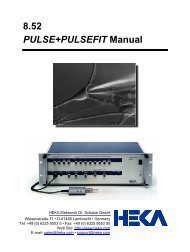
<strong>Manual</strong> 1.1<br />
<strong>TIB</strong> <strong>14S</strong><br />
Trigger Interface
<strong>HEKA</strong> <strong>Elektronik</strong> Phone +49 (0) 6325 / 95 53-0<br />
<strong>Dr</strong>. <strong>Schulze</strong> <strong>GmbH</strong> Fax +49 (0) 6325 / 95 53-50<br />
Wiesenstrasse 71 Web Site www.heka.com<br />
D-67466 Lambrecht/Pfalz Email sales@heka.com<br />
Germany support@heka.com<br />
<strong>HEKA</strong> Electronics Inc. Phone +1 902 624 0606<br />
47 Keddy Bridge Road Fax +1 902 624 0310<br />
R.R. #2 Web Site www.heka.com<br />
Mahone Bay, NS B0J 2E0 Email nasales@heka.com<br />
Canada support@heka.com<br />
<strong>HEKA</strong> Instruments Inc. Phone +1 516 882 1155<br />
2128 Bellmore Avenue Fax +1 516 467 3125<br />
Bellmore, New York 11710-5606 Web Site www.heka.com<br />
USA Email ussales@heka.com<br />
support@heka.com<br />
Title Page: <strong>TIB</strong> <strong>14S</strong> Trigger Interface Box<br />
� 2004-2009 <strong>HEKA</strong> <strong>Elektronik</strong> <strong>Dr</strong>. <strong>Schulze</strong> <strong>GmbH</strong><br />
COM<strong>TIB</strong>/1
Contents<br />
1 Introduction 1<br />
2 Controls and Functions 3<br />
2.1 Front panel controls . . . . . . . . . . . . . . . . . . . . . . 3<br />
2.2 Rear panel controls . . . . . . . . . . . . . . . . . . . . . . . 3<br />
3 Installation 5<br />
3.1 Connection to EPC 9, EPC 10, LIH 8+8 and LIH 1600 . . 5<br />
3.2 Connection to CIO-DIO or PCI-DIO 24H interface card . . 6<br />
3.3 Connection of Magnetic Valve . . . . . . . . . . . . . . . . . 7<br />
3.4 Connection of Peripheral Devices . . . . . . . . . . . . . . . 8<br />
4 Operation 9<br />
4.1 <strong>Manual</strong> Operation . . . . . . . . . . . . . . . . . . . . . . . 9<br />
4.2 Software Support . . . . . . . . . . . . . . . . . . . . . . . . 9<br />
4.3 Control of a Valve Bank . . . . . . . . . . . . . . . . . . . . 10<br />
5 Technical Specifications 11<br />
5.1 Compatibility Chart . . . . . . . . . . . . . . . . . . . . . . 11<br />
5.2 Specifications . . . . . . . . . . . . . . . . . . . . . . . . . . 11
1. Introduction<br />
Electrophysiological setups have to be increasingly flexible nowadays. More<br />
parameters than ever need to be acquired or altered simultaneously during<br />
data acquisition. Controlling bath perfusion or synchronizing other<br />
peripheral devices with data acquisition are standard routines in many<br />
laboratories today. The Tib 14s is fully supported by the <strong>HEKA</strong> software,<br />
enabling the simultaneous control of numerous devices, such as magnetic<br />
valves, shutters, stimulators, etc. within one software application. The<br />
open collector outputs can optionally carry three different voltages which,<br />
in contrast to other digital I/O boards, obligates the use of additional hardware<br />
to drive external devices.<br />
The Tib 14s is a digital output trigger interface to be used with a fully<br />
computer controlled patch clamp amplifier EPC 9 or EPC 10 which have<br />
an AD/DA converter interface built-in or with a standalone interface ITC-<br />
16 or LIH 1600. For control of the Tib 14s from the Tida software an<br />
additional PCI-DIO interface card is required. The Tib 14s provides your<br />
system with 14 TTL outputs and 14 open collector power outputs which<br />
will enable you to control several devices, directly from your software.
2 Introduction<br />
http://www.heka.com
2. Controls and Functions<br />
2.1 Front panel controls<br />
BNC out: 14 BNC connectors numbered 0 to 13<br />
Switches: A switch for each channel is available for manual control of the<br />
channel. Three positions are available: on, off, manual.<br />
LED: Each channel has its own LED indicating the status of channel.<br />
Light on: TTL high, light off: TTL low.<br />
2.2 Rear panel controls<br />
FUSE: Contains a fuse of type T 800 mA L.
4 Controls and Functions<br />
POWER: Power connector to connect to a 50 - 60 Hz power line.<br />
Voltage selector: Allows selection between 110 V and 220 V.<br />
Note: Before connecting the Tib 14s to the local power line,<br />
please make sure that the appropriate voltage is selected.<br />
Digital In (ITC-16): Digital input connector to connect the Tib 14s to<br />
patch clamp amplifiers of the series Epc 9, Epc 10 and interfaces Itc-16,<br />
Lih 1600, Lih 8+8.<br />
TRIGGER OUT: Trigger out connector to be connected to a valve bank<br />
or other peripheral devices.<br />
Digital In (CIO-DIO): Digital input connector of type SUB-D.<br />
http://www.heka.com
3. Installation<br />
3.1 Connection to EPC 9, EPC 10, LIH 8+8<br />
and LIH 1600<br />
The Tib 14s can be connected to the digital I/O connector of Epc 9, Epc<br />
10, Lih 8+8, Itc-16, and Lih 1600 via the connector on the rear panel<br />
labelled Digital In (ITC-16).<br />
Figure 3.1: Digital In Connector (ITC-16)
6 Installation<br />
3.2 Connection to CIO-DIO or PCI-DIO 24H<br />
interface card<br />
In case you are not using the Tib 14s in combination of a device mentioned<br />
above, you can be connected to a CIO-DIO or PCI-DIO24H interface card<br />
via the connector on the rear panel labelled Digital In (CIO-DIO).<br />
http://www.heka.com<br />
Figure 3.2: Digital In Connector (CIO-DIO)
3.3 Connection of Magnetic Valve 7<br />
3.3 Connection of Magnetic Valve<br />
Figure 3.3: Trigger Out Connector<br />
The advantage of the open collector output is the possibility to connect<br />
magnetic valves with various voltages. The open collector output switches<br />
the ground line with a max. output current of 1A. The TTL output (+5V)<br />
switches the output with a max current of 20mA. The TTL output and the<br />
open-collector output are switched in parallel. Each trigger command is<br />
indicated by a LED and activates both, TTL output and a open collector<br />
output.<br />
http://www.heka.com
8 Installation<br />
The opto coupled output avoids ground loops in the setup which often is the<br />
reason for artifacts and increasing noise level during the measurement. For<br />
switching a magnetic valve it is absolutely necessary to mount a protection<br />
diode. The protection diode (mounted anti-parallel, directly at the valve)<br />
avoids spikes during the measurement and protects the output transistor<br />
of the <strong>TIB</strong>14 interface.<br />
3.4 Connection of Peripheral Devices<br />
The BNC connectors at the front panel of the Tib 14s can be used to<br />
control peripheral devices.<br />
http://www.heka.com
4. Operation<br />
4.1 <strong>Manual</strong> Operation<br />
Each of the 14 digital outputs at the front panel is equipped with a manual<br />
switch.<br />
Permanent On Put the switch in the on position to set the corresponding<br />
channel to a TTL high level.<br />
Pulsed Mode, Transiently ON Press down the switch in the manual position<br />
to transiently set the corresponding channel to a TTL high level. The<br />
level remains high as long as you keep the switch in the manual position.<br />
If you release the switch the TTL level returns to low.<br />
4.2 Software Support<br />
Pulse software Trigger commands can be set by the Pulse software,<br />
either manually in the amplifier window or automatically through Macros<br />
or in a Pulse Generator Sequence. Using the Pulse Generator the triggers<br />
will be synchronized with the stimulation signals of Pulse.<br />
PatchMaster software PatchMaster in addition, offers a more flexible<br />
use of the trigger outputs in the Pulse Generator and allows control of<br />
the trigger commands from the Protocol Editor. For more information<br />
about the software support please refer to the brochures and manuals of<br />
the corresponding software package.
10 Operation<br />
4.3 Control of a Valve Bank<br />
Magnetic valves can be driven either in normal mode by connecting the<br />
valve to the 6V, 12V or 24V pins or in boost mode by connecting to<br />
6V boost, 12V boost or 24V boost of the Trigger Out connector. For pin<br />
assignment and a scheme how to connect the valves please refer to figures<br />
3.3 and 3.3.<br />
The boost mode facilitates the opening of the magnetic valves.<br />
Note: The maximal output current of the Tib 14s is limited<br />
to 1 A. Depending on the current requirement of the valves connected<br />
to the Tib 14s only one valve may be open at a time.<br />
http://www.heka.com
5. Technical Specifications<br />
5.1 Compatibility Chart<br />
The following combinations of software and devices are supported:<br />
Software PatchMaster<br />
Pulse<br />
or Tida<br />
Patch EPC 7 EPC 7<br />
Clamp Am-<br />
EPC 9 or<br />
plifier<br />
EPC 10<br />
Interface<br />
CIO-DIO<br />
Board<br />
or PCI-<br />
ITC-16 or<br />
DIO 24H<br />
ITC-16 or<br />
LIH 1600<br />
LIH 1600<br />
Trigger<br />
terfaceIn-<br />
Tib 14s<br />
5.2 Specifications<br />
Digital Out Channels: Tib 14s offers up to 14 trigger outputs<br />
EPC 9 or<br />
EPC 10<br />
CIO-DIO<br />
or PCI-<br />
DIO 24H<br />
Front panel connectors: 14 BNC connectors with TTL level outputs are<br />
available. The state of the trigger outputs is indicated by LED’s.<br />
Rear panel connectors:<br />
� DIGITAL IN (ITC-16) connector to connect the EPC 9 or EPC 10<br />
patch clamp amplifiers or the ITC-16 or LIH 1600 acquisition interfaces<br />
directly. For pin assignment please refer to figure 3.1 on page<br />
5.
12 Technical Specifications<br />
� DIGITAL IN (CIO-DIO) connector to connect the CIO-DIO interface<br />
card. For pin assignment please refer to figure 3.2 on page 6.<br />
� TRIGGER OUT open collector outputs to control up to 14 devices.<br />
The outputs are opto-coupled open collector driven. Three different<br />
power voltages are built-in: 6 V; 12 V; 24 V. In addition, there are<br />
three boosted power voltages available. The boost produces directly<br />
after switching on this channel an additional rectangle pulse of 40 V<br />
amplitude and 23 ms duration. Maximum current output is 1 A. For<br />
pin assignment please refer to figure 3.3 on page 7.<br />
Note: Magnetic devices should be used with a protection<br />
diode.<br />
For a scheme how to connect a magnetic valve please refer to figure<br />
3.3 on page 8.<br />
Dimensions: (D x W x H) (25.0 x 48.3 x 9.0) cm (9.8 x 19.0 x 3.5) inch<br />
Weight: 5.8 kg / 12.6 lbs<br />
Power requirements: 115 V or 230 V, selectable at the rear maximum<br />
power consumption 55 W<br />
Software control: via setting of digital out channels in PatchMaster,<br />
Pulse or Tida. For details see the reference manual or the corresponding<br />
software package.<br />
http://www.heka.com