PIC LCF METER.pdf
PIC LCF METER.pdf
PIC LCF METER.pdf

You also want an ePaper? Increase the reach of your titles
YUMPU automatically turns print PDFs into web optimized ePapers that Google loves.
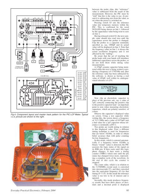
Fig.4. Component layout and master track pattern for the <strong>PIC</strong> <strong>LCF</strong> Meter. Typical<br />
l.c.d. pinouts are shown to the right.<br />
between the probe clips, this “reference”<br />
value is subtracted from the result of the<br />
measurement. However, the <strong>PIC</strong> must be<br />
“told” that this is the value to use. At present<br />
it is subtracting zero from the value, as<br />
set when the power is switched on.<br />
Pressing switch S3 sets the reference<br />
value into temporary memory within the<br />
<strong>PIC</strong>. This is confirmed by the word<br />
NULLED being shown on line 1, followed<br />
by the capacitance value being reset to zero<br />
on line 2.<br />
Having released switch S3, the next sample<br />
value should also read zero until the<br />
capacitance across the probes is changed.<br />
Clip the probes to a capacitor nominally<br />
specified as, say, 1000pF and its actual<br />
value will be displayed on line 2. Note that<br />
the frequency value on line 1 is always the<br />
actual oscillation frequency and is not<br />
affected by the “nulling”.<br />
Be aware that the act of touching the<br />
probe leads with your hands will introduce<br />
additional capacitance across the probes, so<br />
do not hold them while taking value<br />
measurements.<br />
A 470pF ceramic capacitor being monitored<br />
while this text is being written is producing<br />
a frequency of 177653Hz and, after<br />
the reference value has been subtracted by<br />
the software, is shown as having a real<br />
value of 492pF, well within its cataloguestated<br />
tolerance of ±5%.<br />
Now clip an electrolytic capacitor in<br />
place of the previous one, say a value of<br />
1mF, correctly connecting the positive clip<br />
to the positive capacitor lead – an important<br />
point to note when measuring electrolytic<br />
capacitors, which are polarity sensitive, of<br />
course.<br />
Observe the capacitor’s displayed value<br />
on screen. Using a test capacitor while<br />
writing this, the screen shows a frequency<br />
of 311·138Hz and a value of 0·974mF (not<br />
a bad value for a 1mF capacitor whose tolerance<br />
is nominally ±20%!).<br />
Two points are worth noting in relation<br />
to this displayed value. First, a different<br />
timing technique is used for frequencies<br />
that are below 1024Hz, in order to obtain<br />
better accuracy than with pulse counting<br />
for low frequencies.<br />
In this mode, which is entered automatically<br />
if a frequency below 1024Hz (a<br />
binary “round” value) is detected, the <strong>PIC</strong><br />
assesses the logic status of the signal on<br />
its RB6 pin. It then waits until this logic<br />
phase changes. It then starts a timing<br />
counter (TMR1) which runs until the pin<br />
status has changed twice more, representing<br />
a complete cycle of the waveform. At<br />
the end of this cycle the counter is<br />
stopped.<br />
The count value, which is in relation to<br />
the 3·2768MHz crystal used, is converted<br />
into microseconds (T), and then converted<br />
into the equivalent frequency (F) for that<br />
timing (F = 1/T). In this mode the reference<br />
value is too low to be of interest and is<br />
ignored.<br />
Secondly, this mode produces frequency<br />
results that have three places of decimals<br />
and a decimal point is displayed<br />
Everyday Practical Electronics, February 2004 95