Accela Pump Hardware Manual
Accela Pump Hardware Manual
Accela Pump Hardware Manual

Create successful ePaper yourself
Turn your PDF publications into a flip-book with our unique Google optimized e-Paper software.
<strong>Accela</strong> <strong>Pump</strong><br />
<strong>Hardware</strong> <strong>Manual</strong><br />
60157-97000 Revision D February 2009
© 2009 Thermo Fisher Scientific Inc. All rights reserved.<br />
<strong>Accela</strong>, ChromQuest, and Xcalibur are registered trademarks of Thermo Fisher Scientific Inc. in the United<br />
States.<br />
Super Flangeless is a trademark of Upchurch Scientific. PEEK is a trademark of Victrex PLC.<br />
The following are registered trademarks in the United States and other countries: Windows is a registered<br />
trademark of Microsoft Corporation. Teflon is a registered trademark of E. I. du Pont de Nemours and<br />
Company.<br />
Luer-Lok is a registered trademark of Becton, Dickinson and Company.<br />
Thermo Fisher Scientific Inc. provides this document to its customers with a product purchase to use in the<br />
product operation. This document is copyright protected and any reproduction of the whole or any part of this<br />
document is strictly prohibited, except with the written authorization of Thermo Fisher Scientific Inc.<br />
The contents of this document are subject to change without notice. All technical information in this<br />
document is for reference purposes only. System configurations and specifications in this document supersede<br />
all previous information received by the purchaser.<br />
Thermo Fisher Scientific Inc. makes no representations that this document is complete, accurate or errorfree<br />
and assumes no responsibility and will not be liable for any errors, omissions, damage or loss that might<br />
result from any use of this document, even if the information in the document is followed properly.<br />
This document is not part of any sales contract between Thermo Fisher Scientific Inc. and a purchaser. This<br />
document shall in no way govern or modify any Terms and Conditions of Sale, which Terms and Conditions of<br />
Sale shall govern all conflicting information between the two documents.<br />
Revision history: Revision A, September 2006; Revision B, January 2007; Revision C, March 2008;<br />
Revision D, February 2009<br />
Software versions: Xcalibur 2.0 or higher, ChromQuest 4.2 with SP 2 or higher, ChromQuest SI version 5.0<br />
For Research Use Only. Not regulated for medical or veterinary diagnostic use by U.S. Federal Drug<br />
Administration or other competent authorities.
Regulatory Compliance<br />
Thermo Fisher Scientific performs complete testing and evaluation of its products to ensure full compliance with<br />
applicable domestic and international regulations. When the system is delivered to you, it meets all pertinent<br />
electromagnetic compatibility (EMC) and safety standards as described in the next section by product name.<br />
Changes that you make to your system might void compliance with one or more of these EMC and safety standards.<br />
Changes to your system include replacing a part or adding components, options, or peripherals not specifically<br />
authorized and qualified by Thermo Fisher Scientific. To ensure continued compliance with EMC and safety standards,<br />
replacement parts and additional components, options, and peripherals must be ordered from Thermo Fisher Scientific<br />
or one of its authorized representatives.<br />
<strong>Accela</strong> <strong>Pump</strong><br />
EMC Directive 89/336/EEC, 92/31/EEC, 93/68/EEC<br />
EMC compliance has been evaluated by TUV Rheinland of North America, Inc.<br />
EN 61326 1997; A1, 1998; A2, 2001; A3, 2003 EN 61000-4-4 1995; A1, 2000; A2, 2001<br />
EN 61000-3-2 2000 EN 61000-4-5 2001<br />
EN 61000-3-3 1995; A1, 2001 EN 61000-4-6 2003<br />
EN 61000-4-2 2001 EN 61000-4-8 2001<br />
EN 61000-4-3 2002 EN 61000-4-11 2001<br />
FCC Class A, CFR 47 Part 15 Subpart B: 2005<br />
Low Voltage Safety Compliance<br />
This device complies with Low Voltage Directive 73/23/EEC and harmonized standard EN 61010-1:2001, IEC<br />
61010-1:2002, UL 61010 A-1:2004, CAN/CSA 22.2 61010-1:2004.<br />
FCC Compliance Statement<br />
THIS DEVICE COMPLIES WITH PART 15 OF THE FCC RULES. OPERATION IS SUBJECT TO<br />
THE FOLLOWING TWO CONDITIONS: (1) THIS DEVICE MAY NOT CAUSE HARMFUL<br />
INTERFERENCE, AND (2) THIS DEVICE MUST ACCEPT ANY INTERFERENCE RECEIVED,<br />
INCLUDING INTERFERENCE THAT MAY CAUSE UNDESIRED OPERATION.
CAUTION Read and understand the various precautionary notes, signs, and symbols contained inside<br />
this manual pertaining to the safe use and operation of this product before using the device.<br />
Notice on Lifting and Handling of<br />
Thermo Scientific Instruments<br />
For your safety, and in compliance with international regulations, the physical handling of this Thermo Fisher Scientific<br />
instrument requires a team effort to lift and/or move the instrument. This instrument is too heavy and/or bulky for one<br />
person alone to handle safely.<br />
Notice on the Proper Use of<br />
Thermo Scientific Instruments<br />
In compliance with international regulations: Use of this instrument in a manner not specified by Thermo Fisher<br />
Scientific could impair any protection provided by the instrument.<br />
Notice on the Susceptibility<br />
to Electromagnetic Transmissions<br />
Your instrument is designed to work in a controlled electromagnetic environment. Do not use radio frequency<br />
transmitters, such as mobile phones, in close proximity to the instrument.<br />
For manufacturing location, see the label on the instrument.
WEEE Compliance<br />
This product is required to comply with the European Union’s Waste Electrical & Electronic<br />
Equipment (WEEE) Directive 2002/96/EC. It is marked with the following symbol:<br />
Thermo Fisher Scientific has contracted with one or more recycling or disposal companies in each<br />
European Union (EU) Member State, and these companies should dispose of or recycle this product.<br />
See www.thermo.com/WEEERoHS for further information on Thermo Fisher Scientific’s compliance<br />
with these Directives and the recyclers in your country.<br />
WEEE Konformität<br />
Dieses Produkt muss die EU Waste Electrical & Electronic Equipment (WEEE) Richtlinie 2002/96/EC<br />
erfüllen. Das Produkt ist durch folgendes Symbol gekennzeichnet:<br />
Thermo Fisher Scientific hat Vereinbarungen mit Verwertungs-/Entsorgungsfirmen in allen EU-<br />
Mitgliedsstaaten getroffen, damit dieses Produkt durch diese Firmen wiederverwertet oder entsorgt<br />
werden kann. Mehr Information über die Einhaltung dieser Anweisungen durch Thermo Fisher<br />
Scientific, über die Verwerter, und weitere Hinweise, die nützlich sind, um die Produkte zu<br />
identifizieren, die unter diese RoHS Anweisung fallen, finden sie unter www.thermo.com/<br />
WEEERoHS.
Conformité DEEE<br />
Ce produit doit être conforme à la directive européenne (2002/96/EC) des Déchets d'Equipements<br />
Electriques et Electroniques (DEEE). Il est marqué par le symbole suivant:<br />
Thermo Fisher Scientific s'est associé avec une ou plusieurs compagnies de recyclage dans chaque état<br />
membre de l’union européenne et ce produit devrait être collecté ou recyclé par celles-ci. Davantage<br />
d'informations sur la conformité de Thermo Fisher Scientific à ces directives, les recycleurs dans votre<br />
pays et les informations sur les produits Thermo Fisher Scientific qui peuvent aider la détection des<br />
substances sujettes à la directive RoHS sont disponibles sur www.thermo.com/WEEERoHS.
CAUTION Symbol CAUTION VORSICHT ATTENTION PRECAUCION AVVERTENZA<br />
Electric Shock: This instrument uses<br />
high voltages that can cause personal<br />
injury. Before servicing, shut down the<br />
instrument and disconnect the instrument<br />
from line power. Keep the top cover on<br />
while operating the instrument. Do not<br />
remove protective covers from PCBs.<br />
Chemical: This instrument might contain<br />
hazardous chemicals. Wear gloves when<br />
handling toxic, carcinogenic, mutagenic,<br />
or corrosive or irritant chemicals. Use<br />
approved containers and proper<br />
procedures to dispose waste oil.<br />
Heat: Before servicing the instrument,<br />
allow any heated components to cool.<br />
Fire: Use care when operating the system<br />
in the presence of flammable gases.<br />
Eye Hazard: Eye damage could occur<br />
from splattered chemicals or flying<br />
particles. Wear safety glasses when<br />
handling chemicals or servicing the<br />
instrument.<br />
General Hazard: A hazard is present that<br />
is not included in the above categories.<br />
Also, this symbol appears on the<br />
instrument to refer the user to instructions<br />
in this manual.<br />
When the safety of a procedure is<br />
questionable, contact your local Technical<br />
Support organization for Thermo Fisher<br />
Scientific San Jose Products.<br />
Elektroschock: In diesem Gerät werden<br />
Hochspannungen verwendet, die<br />
Verletzungen verursachen können. Vor<br />
Wartungsarbeiten muß das Gerät<br />
abgeschaltet und vom Netz getrennt<br />
werden. Betreiben Sie Wartungsarbeiten<br />
nicht mit abgenommenem Deckel. Nehmen<br />
Sie die Schutzabdeckung von Leiterplatten<br />
nicht ab.<br />
Chemikalien: Dieses Gerät kann<br />
gefährliche Chemikalien enthalten. Tragen<br />
Sie Schutzhandschuhe beim Umgang mit<br />
toxischen, karzinogenen, mutagenen oder<br />
ätzenden/reizenden Chemikalien.<br />
Entsorgen Sie verbrauchtes Öl<br />
entsprechend den Vorschriften in den<br />
vorgeschriebenen Behältern.<br />
Hitze: Warten Sie erhitzte Komponenten<br />
erst nachdem diese sich abgekühlt haben.<br />
Feuer: Beachten Sie die einschlägigen<br />
VorsichtsmaBnahmen, wenn Sie das<br />
System in Gegenwart von entzündbaren<br />
Gasen betreiben.<br />
Verletzungsgefahr der Augen:<br />
Verspritzte Chemikalien oder kleine<br />
Partikel können Augenverletzungen<br />
verursachen. Tragen Sie beim Umgang mit<br />
Chemikalien oder bei der Wartung des<br />
Gerätes eine Schutzbrille.<br />
Allgemeine Gefahr: Es besteht eine<br />
weitere Gefahr, die nicht in den<br />
vorstehenden Kategorien beschrieben ist.<br />
Dieses Symbol wird im Handbuch<br />
auBerdem dazu verwendet, um den<br />
Benutzer auf Anweisungen hinzuweisen.<br />
Wenn Sie sich über die Sicherheit eines<br />
Verfahrens im unklaren sind, setzen Sie<br />
sich, bevor Sie fortfahren, mit Ihrer<br />
lokalen technischen<br />
Unterstützungsorganisation für Thermo<br />
Fisher Scientific San Jose Produkte in<br />
Verbindung.<br />
Choc électrique: L’instrument utilise des<br />
tensions capables d’infliger des blessures<br />
corprelles. L’instrument doit être arrêté et<br />
débranché de la source de courant avant<br />
tout intervention. Ne pas utiliser<br />
l’instrument sans son couvercle. Ne pas<br />
elensver les étuis protecteurs des cartes de<br />
circuits imprimés.<br />
Chimique: Des produits chemiques<br />
dangereux peuven se trouver dans<br />
l’instrument. Proted dos gants pour<br />
manipuler tous produits chemiques<br />
toxiques, cancérigènes, mutagènes, ou<br />
corrosifs/irritants. Utiliser des récipients<br />
et des procédures homologuées pour se<br />
débarrasser des déchets d’huile.<br />
Haute Temperature: Permettre aux<br />
composants chauffés de refroidir avant<br />
tout intervention.<br />
Incendie: Agir avec précaution lors de<br />
l’utilisation du système en présence de<br />
gaz inflammables.<br />
Danger pour les yeux: Dex projections<br />
chimiques, liquides, ou solides peuvent<br />
être dangereuses pour les yeux. Porter des<br />
lunettes de protection lors de toute<br />
manipulationde produit chimique ou pour<br />
toute intervention sur l’instrument.<br />
Danger général: Indique la présence<br />
d;un risque n’appartenant pas aux<br />
catégories citées plus haut. Ce symbole<br />
figure également sur l’instrument pour<br />
renvoyer l’utilisateur aux instructions du<br />
présent manuel.<br />
Si la sûreté d’un procédure est incertaine,<br />
avant de continuer, contacter le plus<br />
proche Service Clientèle pour les produits<br />
de Thermo Fisher Scientific San Jose.<br />
Descarga eléctrica: Este instrumento<br />
utiliza altas tensiones, capaces de<br />
producir lesiones personales. Antes de<br />
dar servicio de mantenimiento al<br />
instrumento, éste debera apagarse y<br />
desconectarse de la línea de alimentacion<br />
eléctrica. No opere el instrumento sin sus<br />
cubiertas exteriores quitadas. No remueva<br />
las cubiertas protectoras de las tarjetas<br />
de circuito impreso.<br />
Química: El instrumento puede contener<br />
productos quimicos peligrosos. Utilice<br />
guantes al manejar productos quimicos<br />
tóxicos, carcinogenos, mutagenos o<br />
corrosivos/irritantes. Utilice recipientes y<br />
procedimientos aprobados para<br />
deshacerse del aceite usado.<br />
Altas temperaturas: Permita que lop<br />
componentes se enfríen, ante de efectuar<br />
servicio de mantenimiento.<br />
Fuego: Tenga cuidado al operar el<br />
sistema en presencia de gases<br />
inflamables.<br />
Peligro par los ojos: Las salicaduras de<br />
productos químicos o particulas que<br />
salten bruscamente pueden causar<br />
lesiones en los ojos. Utilice anteojos<br />
protectores al mnipular productos<br />
químicos o al darle servicio de<br />
mantenimiento al instrumento.<br />
Peligro general: Significa que existe un<br />
peligro no incluido en las categorias<br />
anteriores. Este simbolo también se utiliza<br />
en el instrumento par referir al usuario a<br />
las instrucciones contenidas en este<br />
manual.<br />
Cuando la certidumbre acerca de un<br />
procedimiento sea dudosa, antes de<br />
proseguir, pongase en contacto con la<br />
Oficina de Asistencia Tecnica local para<br />
los productos de Thermo Fisher Scientific<br />
San Jose.<br />
Shock da folgorazione. L’apparecchio è<br />
alimentato da corrente ad alta tensione<br />
che puo provocare lesioni fisiche. Prima di<br />
effettuare qualsiasi intervento di<br />
manutenzione occorre spegnere ed isolare<br />
l’apparecchio dalla linea elettrica. Non<br />
attivare lo strumento senza lo schermo<br />
superiore. Non togliere i coperchi a<br />
protezione dalle schede di circuito<br />
stampato (PCB).<br />
Prodotti chimici. Possibile presenza di<br />
sostanze chimiche pericolose<br />
nell’apparecchio. Indossare dei guanti per<br />
maneggiare prodotti chimici tossici,<br />
cancerogeni, mutageni, o<br />
corrosivi/irritanti. Utilizzare contenitori<br />
aprovo e seguire la procedura indicata per<br />
lo smaltimento dei residui di olio.<br />
Calore. Attendere che i componenti<br />
riscaldati si raffreddino prima di<br />
effetturare l’intervento di manutenzione.<br />
Incendio. Adottare le dovute precauzioni<br />
quando si usa il sistema in presenza di gas<br />
infiammabili.<br />
Pericolo per la vista. Gli schizzi di<br />
prodotti chimici o delle particelle presenti<br />
nell’aria potrebbero causare danni alla<br />
vista. Indossare occhiali protettivi quando<br />
si maneggiano prodotti chimici o si<br />
effettuano interventi di manutenzione<br />
sull’apparecchio.<br />
Pericolo generico. Pericolo non<br />
compreso tra le precedenti categorie.<br />
Questo simbolo è utilizzato inoltre<br />
sull’apparecchio per segnalare all’utente<br />
di consultare le istruzioni descritte nel<br />
presente manuale.<br />
Quando e in dubbio la misura di sicurezza<br />
per una procedura, prima di continuare, si<br />
prega di mettersi in contatto con il<br />
Servizio di Assistenza Tecnica locale per i<br />
prodotti di Thermo Fisher Scientific San<br />
Jose.
CAUTION Symbol CAUTION<br />
Electric Shock: This instrument uses<br />
high voltages that can cause personal<br />
injury. Before servicing, shut down the<br />
instrument and disconnect the instrument<br />
from line power. Keep the top cover on<br />
while operating the instrument. Do not<br />
remove protective covers from PCBs.<br />
Chemical: This instrument might contain<br />
hazardous chemicals. Wear gloves when<br />
handling toxic, carcinogenic, mutagenic,<br />
or corrosive or irritant chemicals. Use<br />
approved containers and proper<br />
procedures to dispose waste oil.<br />
Heat: Before servicing the instrument,<br />
allow any heated components to cool.<br />
Fire: Use care when operating the system<br />
in the presence of flammable gases.<br />
Eye Hazard: Eye damage could occur<br />
from splattered chemicals or flying<br />
particles. Wear safety glasses when<br />
handling chemicals or servicing the<br />
instrument.<br />
General Hazard: A hazard is present that<br />
is not included in the above categories.<br />
Also, this symbol appears on the<br />
instrument to refer the user to instructions<br />
in this manual.<br />
When the safety of a procedure is<br />
questionable, contact your local Technical<br />
Support organization for Thermo Fisher<br />
Scientific San Jose Products.
Contents<br />
Thermo Scientific <strong>Accela</strong> <strong>Pump</strong> <strong>Hardware</strong> <strong>Manual</strong> ix<br />
C<br />
Preface . . . . . . . . . . . . . . . . . . . . . . . . . . . . . . . . . . . . . . . . . . . . . . . . . . . . . . . . . . . . .xiii<br />
Related Documentation . . . . . . . . . . . . . . . . . . . . . . . . . . . . . . . . . . . . . . . . . .xiii<br />
Safety and Special Notices . . . . . . . . . . . . . . . . . . . . . . . . . . . . . . . . . . . . . . . .xiii<br />
Special Precautions for the <strong>Accela</strong> <strong>Pump</strong>. . . . . . . . . . . . . . . . . . . . . . . . . . . . . .xiv<br />
Good Laboratory Practices . . . . . . . . . . . . . . . . . . . . . . . . . . . . . . . . . . . . . . . . xv<br />
Contacting Us . . . . . . . . . . . . . . . . . . . . . . . . . . . . . . . . . . . . . . . . . . . . . . . . xvii<br />
Chapter 1 Introduction . . . . . . . . . . . . . . . . . . . . . . . . . . . . . . . . . . . . . . . . . . . . . . . . . . . . . . . . . . .1<br />
Functional Description . . . . . . . . . . . . . . . . . . . . . . . . . . . . . . . . . . . . . . . . . . . . 2<br />
Vacuum Degasser Assembly. . . . . . . . . . . . . . . . . . . . . . . . . . . . . . . . . . . . . . . 3<br />
Liquid Displacement Assembly (LDA) . . . . . . . . . . . . . . . . . . . . . . . . . . . . . . 3<br />
Purge Valve . . . . . . . . . . . . . . . . . . . . . . . . . . . . . . . . . . . . . . . . . . . . . . . . . . . 4<br />
Pulse Dampening Assembly. . . . . . . . . . . . . . . . . . . . . . . . . . . . . . . . . . . . . . . 5<br />
Dynamic Mixer . . . . . . . . . . . . . . . . . . . . . . . . . . . . . . . . . . . . . . . . . . . . . . . . 6<br />
Status LEDs. . . . . . . . . . . . . . . . . . . . . . . . . . . . . . . . . . . . . . . . . . . . . . . . . . . 7<br />
Specifications. . . . . . . . . . . . . . . . . . . . . . . . . . . . . . . . . . . . . . . . . . . . . . . . . . . . 8<br />
Chapter 2 Installation . . . . . . . . . . . . . . . . . . . . . . . . . . . . . . . . . . . . . . . . . . . . . . . . . . . . . . . . . . . .9<br />
Installation Checklist. . . . . . . . . . . . . . . . . . . . . . . . . . . . . . . . . . . . . . . . . . . . . 10<br />
Unpacking and Inspecting the Instrument . . . . . . . . . . . . . . . . . . . . . . . . . . . . 11<br />
Making the Initial Instrument Preparations. . . . . . . . . . . . . . . . . . . . . . . . . . . . 12<br />
Making the Initial Back Panel Connections. . . . . . . . . . . . . . . . . . . . . . . . . . . . 13<br />
Connecting the Power Cable . . . . . . . . . . . . . . . . . . . . . . . . . . . . . . . . . . . . . 14<br />
Connecting the USB Cable . . . . . . . . . . . . . . . . . . . . . . . . . . . . . . . . . . . . . . 14<br />
Connecting the System Interconnect Cable . . . . . . . . . . . . . . . . . . . . . . . . . . 15<br />
Connecting the Low-Pressure Solvent Lines . . . . . . . . . . . . . . . . . . . . . . . . . . . 17<br />
Assembling the Solvent Reservoir Bottles. . . . . . . . . . . . . . . . . . . . . . . . . . . . 17<br />
Installing the Super Flangeless Fittings . . . . . . . . . . . . . . . . . . . . . . . . . . . . . 19<br />
Connecting the <strong>Pump</strong> to the Autosampler. . . . . . . . . . . . . . . . . . . . . . . . . . . . . 22<br />
Powering On for the First Time . . . . . . . . . . . . . . . . . . . . . . . . . . . . . . . . . . . . 24<br />
Chapter 3 Data System Instrument Configuration . . . . . . . . . . . . . . . . . . . . . . . . . . . . . . . . . . .25<br />
Adding the <strong>Pump</strong> to the Xcalibur Instrument Configuration . . . . . . . . . . . . . . 25<br />
Configuring the Signal Polarity for the <strong>Accela</strong> AS in Xcalibur . . . . . . . . . . . . . . 28<br />
Configuring an <strong>Accela</strong> Instrument in ChromQuest. . . . . . . . . . . . . . . . . . . . . . 30
Contents<br />
Chapter 4 Preparing the <strong>Pump</strong> for Operation . . . . . . . . . . . . . . . . . . . . . . . . . . . . . . . . . . . . . . .37<br />
Removing Air from the Solvent Lines . . . . . . . . . . . . . . . . . . . . . . . . . . . . . . . . 37<br />
Using the Data System to Start and Stop the Solvent Flow . . . . . . . . . . . . . . . . 38<br />
Using Xcalibur to Start and Stop the Solvent Flow . . . . . . . . . . . . . . . . . . . . 39<br />
Using ChromQuest to Start and Stop the Solvent Flow. . . . . . . . . . . . . . . . . 40<br />
Priming the Pulse Dampener. . . . . . . . . . . . . . . . . . . . . . . . . . . . . . . . . . . . . . . 41<br />
Chapter 5 Diagnostics. . . . . . . . . . . . . . . . . . . . . . . . . . . . . . . . . . . . . . . . . . . . . . . . . . . . . . . . . . .43<br />
Monitoring the <strong>Pump</strong> Pulsation . . . . . . . . . . . . . . . . . . . . . . . . . . . . . . . . . . . . 43<br />
Using Xcalibur to Monitor the <strong>Pump</strong> Status . . . . . . . . . . . . . . . . . . . . . . . . . 44<br />
Using ChromQuest to Monitor the <strong>Pump</strong> Status . . . . . . . . . . . . . . . . . . . . . 45<br />
Testing the <strong>Pump</strong> Proportioning. . . . . . . . . . . . . . . . . . . . . . . . . . . . . . . . . . . . 46<br />
Determining the Delay Volume of the <strong>Pump</strong> . . . . . . . . . . . . . . . . . . . . . . . . . . 49<br />
Chapter 6 Maintenance . . . . . . . . . . . . . . . . . . . . . . . . . . . . . . . . . . . . . . . . . . . . . . . . . . . . . . . . .53<br />
Flushing the Piston Guide Bushings . . . . . . . . . . . . . . . . . . . . . . . . . . . . . . . . . 54<br />
Minimizing <strong>Pump</strong> Pulsation . . . . . . . . . . . . . . . . . . . . . . . . . . . . . . . . . . . . . . . 55<br />
Removing Air from the Piston Chambers . . . . . . . . . . . . . . . . . . . . . . . . . . . 55<br />
Cleaning the LDA Components without Disassembling the LDA. . . . . . . . . 56<br />
Cleaning the LDA Components after Disassembling the LDA . . . . . . . . . . . . . 58<br />
Cleaning the Check Valves . . . . . . . . . . . . . . . . . . . . . . . . . . . . . . . . . . . . . . 58<br />
Cleaning the Pistons . . . . . . . . . . . . . . . . . . . . . . . . . . . . . . . . . . . . . . . . . . . 58<br />
Cleaning the Displacement Chambers and the Inlet Module. . . . . . . . . . . . . 59<br />
Removing the LDA from the <strong>Pump</strong> . . . . . . . . . . . . . . . . . . . . . . . . . . . . . . . . . 60<br />
Disassembling the LDA. . . . . . . . . . . . . . . . . . . . . . . . . . . . . . . . . . . . . . . . . . . 64<br />
Removing the Holding Hooks, Bushings, and Pistons from the LDA Body . 64<br />
Removing the Stacked Components from the LDA Body . . . . . . . . . . . . . . . 66<br />
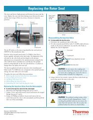
Replacing the Primary Pistons Seals. . . . . . . . . . . . . . . . . . . . . . . . . . . . . . . . . . 67<br />
Assembling the Liquid Displacement Assembly. . . . . . . . . . . . . . . . . . . . . . . . . 70<br />
Connecting the Quaternary Inlet Module to the LDA Body . . . . . . . . . . . . . 70<br />
Inserting the Check Valves into the Lower Displacement Chamber. . . . . . . . 71<br />
Inserting the Components of the LDA Stack into the LDA Body . . . . . . . . . 71<br />
Installing the Holding Hooks and the Piston Assemblies. . . . . . . . . . . . . . . . 73<br />
Connecting the LDA to the <strong>Pump</strong> . . . . . . . . . . . . . . . . . . . . . . . . . . . . . . . . . . 75<br />
Servicing the Proportioning Valves . . . . . . . . . . . . . . . . . . . . . . . . . . . . . . . . . . 77<br />
Replacing the Solvent Reservoir Filters . . . . . . . . . . . . . . . . . . . . . . . . . . . . . . . 79<br />
Replacing a Fuse . . . . . . . . . . . . . . . . . . . . . . . . . . . . . . . . . . . . . . . . . . . . . . . . 80<br />
Chapter 7 Troubleshooting. . . . . . . . . . . . . . . . . . . . . . . . . . . . . . . . . . . . . . . . . . . . . . . . . . . . . . .81<br />
Troubleshooting Tips . . . . . . . . . . . . . . . . . . . . . . . . . . . . . . . . . . . . . . . . . . . . 81<br />
General System Troubleshooting. . . . . . . . . . . . . . . . . . . . . . . . . . . . . . . . . . . . 82<br />
<strong>Pump</strong> Troubleshooting Guide. . . . . . . . . . . . . . . . . . . . . . . . . . . . . . . . . . . . . . 84<br />
<strong>Pump</strong> Pulsation. . . . . . . . . . . . . . . . . . . . . . . . . . . . . . . . . . . . . . . . . . . . . . . . . 87<br />
Normal Pressure Pulsation. . . . . . . . . . . . . . . . . . . . . . . . . . . . . . . . . . . . . . . 87<br />
Abnormal Pressure Pulsation . . . . . . . . . . . . . . . . . . . . . . . . . . . . . . . . . . . . . 87<br />
x <strong>Accela</strong> <strong>Pump</strong> <strong>Hardware</strong> <strong>Manual</strong> Thermo Scientific
Baseline Noise at Low Pressures. . . . . . . . . . . . . . . . . . . . . . . . . . . . . . . . . . . . . 88<br />
Insufficient Solvent Flow from the <strong>Pump</strong> Outlet. . . . . . . . . . . . . . . . . . . . . . . . 89<br />
<strong>Pump</strong> Cavitation . . . . . . . . . . . . . . . . . . . . . . . . . . . . . . . . . . . . . . . . . . . . . . 89<br />
Blocked Proportioning Valve. . . . . . . . . . . . . . . . . . . . . . . . . . . . . . . . . . . . . 89<br />
Blocked Check Valve. . . . . . . . . . . . . . . . . . . . . . . . . . . . . . . . . . . . . . . . . . . 90<br />
Irreproducible Retention Times . . . . . . . . . . . . . . . . . . . . . . . . . . . . . . . . . . . . 90<br />
Chapter 8 Accessories and Replacement Parts . . . . . . . . . . . . . . . . . . . . . . . . . . . . . . . . . . . .91<br />
Liquid Displacement Assembly (LDA) Parts . . . . . . . . . . . . . . . . . . . . . . . . . . . 92<br />
<strong>Accela</strong> <strong>Pump</strong> Accessory Kit . . . . . . . . . . . . . . . . . . . . . . . . . . . . . . . . . . . . . . . . 97<br />
<strong>Accela</strong> System Kit . . . . . . . . . . . . . . . . . . . . . . . . . . . . . . . . . . . . . . . . . . . . . . . 97<br />
Solvent Interconnect Kit . . . . . . . . . . . . . . . . . . . . . . . . . . . . . . . . . . . . . . . . . . 98<br />
Other Parts and Assemblies . . . . . . . . . . . . . . . . . . . . . . . . . . . . . . . . . . . . . . . . 98<br />
Appendix A Discontinued Versions of the <strong>Accela</strong> <strong>Pump</strong>. . . . . . . . . . . . . . . . . . . . . . . . . . . . . .101<br />
Installing the Check Valves in the Discontinued LDA. . . . . . . . . . . . . . . . . . . 101<br />
Installing the Check Valves and Holders . . . . . . . . . . . . . . . . . . . . . . . . . . . 101<br />
Installing the Screw-In Check Valves (discontinued version) . . . . . . . . . . . . 102<br />
Installing the Components of the Discontinued LDA Stack . . . . . . . . . . . . . . 104<br />
Index . . . . . . . . . . . . . . . . . . . . . . . . . . . . . . . . . . . . . . . . . . . . . . . . . . . . . . . . . . . . . . .107<br />
Contents<br />
Thermo Scientific <strong>Accela</strong> <strong>Pump</strong> <strong>Hardware</strong> <strong>Manual</strong> xi
Preface<br />
Related Documentation<br />
This <strong>Accela</strong> <strong>Pump</strong> <strong>Hardware</strong> <strong>Manual</strong> provides you with information on how to install,<br />
maintain, and troubleshoot the <strong>Accela</strong> <strong>Pump</strong>. You operate the <strong>Accela</strong> <strong>Pump</strong> from a computer<br />
running Xcalibur (version 2.0 or higher) or ChromQuest (version 4.2 or higher).<br />
In addition to this guide, Thermo Fisher Scientific provides the following documents for the<br />
<strong>Accela</strong> <strong>Pump</strong>:<br />
• <strong>Accela</strong> Preinstallation Requirements Guide<br />
• <strong>Accela</strong> Getting Connected Guide<br />
Safety and Special Notices<br />
• <strong>Accela</strong> Getting Started with Xcalibur Guide<br />
Make sure you follow the precautionary statements presented in this guide. The safety and<br />
other special notices appear in boxes.<br />
Safety and special notices include the following:<br />
CAUTION Highlights hazards to humans, property, or the environment. Each CAUTION<br />
notice is accompanied by an appropriate CAUTION symbol.<br />
IMPORTANT Highlights information necessary to prevent damage to software, loss of<br />
data, or invalid test results; or might contain information that is critical for optimal<br />
performance of the system.<br />
Note Highlights information of general interest.<br />
Tip Highlights helpful information that can make a task easier.<br />
Thermo Scientific <strong>Accela</strong> <strong>Pump</strong> <strong>Hardware</strong> <strong>Manual</strong> xiii<br />
P
Preface<br />
Special Precautions for the <strong>Accela</strong> <strong>Pump</strong><br />
Note the caution sticker on the front panel of the <strong>Accela</strong> <strong>Pump</strong> shown below. The drive arm<br />
mechanism that controls the movement of the pistons contains moving parts that can pinch<br />
your fingers.<br />
White, insulated, electrical wires connect the actuating coils at the ends of the proportioning<br />
valves to the pump as shown below. Take care not to pinch these wires when you remove the<br />
liquid displacement assembly (LDA) from the front panel of the pump to perform<br />
maintenance.<br />
Drive arm<br />
mechanism<br />
Insulated wires Actuating coil<br />
xiv <strong>Accela</strong> <strong>Pump</strong> <strong>Hardware</strong> <strong>Manual</strong> Thermo Scientific
Good Laboratory Practices<br />
Keep Good Records<br />
Chemical Toxicity<br />
Sample Preparation<br />
To obtain optimal performance from your LC system and to prevent personal injury or injury<br />
to the environment, do the following:<br />
• Keep good records.<br />
• Read the manufacturers’ Material Safety Data Sheets (MSDSs) for the chemicals being<br />
used in your laboratory.<br />
• Remove particulate matter from your samples before you inject them into the liquid<br />
chromatograph.<br />
• Use HPLC-grade solvents.<br />
• Connect the drainage tubes from the pump, autosampler, and detector to an appropriate<br />
waste receptacle. Dispose of solvents as specified by local regulations.<br />
To help identify and isolate problems with either your equipment or your methodology, keep<br />
good records of all system conditions (for example, peak shape, resolution between adjacent<br />
peaks, and % RSDs on retention times and peak areas). At a minimum, keep a chromatogram<br />
of a typical sample and standard mixture, well documented with system conditions, for future<br />
reference. Careful comparison of retention times, peak shapes, peak sensitivity, and baseline<br />
noise can provide valuable clues to identifying and solving future problems.<br />
Although the large volume of toxic and flammable solvents used and stored in laboratories can<br />
be quite dangerous, do not ignore the potential hazards posed by your samples. Take special<br />
care to read and follow all precautions that ensure proper ventilation, storage, handling, and<br />
disposal of both solvents and samples. Become familiar with the toxicity data and potential<br />
hazards associated with all chemicals by referring to the manufacturers’ Material Safety Data<br />
Sheets.<br />
Always consider the solubility of your sample in the solvent/mobile phase. Sample<br />
precipitation can plug the column, tubing, or flowcell causing flow restriction. This<br />
obstruction can result in irreparable damage to the system. To avoid damage caused by<br />
particulate matter, filter the samples through 0.45 or 0.2 micron (or less) filters.<br />
Preface<br />
Thermo Scientific <strong>Accela</strong> <strong>Pump</strong> <strong>Hardware</strong> <strong>Manual</strong> xv
Preface<br />
Solvent Requirement<br />
Many chemical manufacturers provide a line of high-purity or HPLC-grade reagents that are<br />
free of chemical impurities. Routine filtration of all solvents or eluents through a 0.45 or<br />
0.2 micron (or less) fluorocarbon filter before placing them in the solvent reservoir<br />
significantly prolongs the life and effectiveness of the inlet filters, check valves and seals,<br />
injector, and column. Typically, HPLC-grade solvents do not require filtration.<br />
Solvent Disposal<br />
High-pressure Systems and Leaks<br />
Choose a mobile phase that is compatible with the sample and column you have selected for<br />
your separation. Remember that some solvents are corrosive to stainless steel.<br />
Make sure you have a solvent waste container or other kind of drain system available at or<br />
below the benchtop level. Most solvents have special disposal requirements and should not be<br />
disposed of directly down a drain. Follow all governmental regulations when disposing of any<br />
chemical.<br />
LC systems operate at high pressures. Because liquids are not highly compressible they do not<br />
store much energy. Accordingly, there is little immediate danger from the high pressures in an<br />
LC system. However, if a leak occurs, correct it as soon as possible. Always wear eye and skin<br />
protection when operating or maintaining an LC system. Always shut down the system and<br />
return it to atmospheric pressure before attempting any maintenance.<br />
xvi <strong>Accela</strong> <strong>Pump</strong> <strong>Hardware</strong> <strong>Manual</strong> Thermo Scientific
Contacting Us<br />
There are several ways to contact Thermo Fisher Scientific for the information you need.<br />
� To contact Technical Support<br />
Phone 800-532-4752<br />
Fax 561-688-8736<br />
E-mail us.techsupport.analyze@thermofisher.com<br />
Knowledge base www.thermokb.com<br />
Find software updates and utilities to download at mssupport.thermo.com.<br />
� To contact Customer Service for ordering information<br />
Phone 800-532-4752<br />
Fax 561-688-8731<br />
E-mail us.customer-support.analyze@thermofisher.com<br />
Web site www.thermo.com/ms<br />
� To copy manuals from the Internet<br />
Go to mssupport.thermo.com and click Customer <strong>Manual</strong>s in the left margin of the<br />
window.<br />
� To suggest changes to documentation or to Help<br />
• Complete a brief survey about this document by clicking the link below. Thank you<br />
in advance for your help.<br />
• Send an e-mail message to the Technical Publications Editor at<br />
techpubs-lcms@thermofisher.com.<br />
Preface<br />
Thermo Scientific <strong>Accela</strong> <strong>Pump</strong> <strong>Hardware</strong> <strong>Manual</strong> xvii
Introduction<br />
The <strong>Accela</strong> <strong>Pump</strong> is a member of the <strong>Accela</strong> family of ultra high performance liquid<br />
chromatography instruments.<br />
This chapter provides an introduction to the <strong>Accela</strong> <strong>Pump</strong> shown in Figure 1.<br />
Contents<br />
• Functional Description<br />
• Specifications<br />
Figure 1. <strong>Accela</strong> <strong>Pump</strong><br />
Thermo Scientific <strong>Accela</strong> <strong>Pump</strong> <strong>Hardware</strong> <strong>Manual</strong> 1<br />
1
1 Introduction<br />
Functional Description<br />
Functional Description<br />
The <strong>Accela</strong> <strong>Pump</strong> is a quaternary, low-pressure mixing pump with built-in solvent degassing<br />
and pulse dampening systems. The pumping system provides optimum performance in the<br />
flow rate ranges needed for liquid chromatography and mass spectrometry. You can run<br />
precise gradients from 50 to 1000 μL/min. An extremely low gradient delay volume of 65 μL<br />
ensures minimum system cycle times. The integral vacuum degasser offers superb solvent<br />
degassing efficiency with less than 500 μL of volume, and the pulse dampener produces stable<br />
flow rates without the addition of any gradient delay volume.<br />
The <strong>Accela</strong> <strong>Pump</strong> is a benchtop unit for inclusion in the <strong>Accela</strong> ultra high performance liquid<br />
chromatograph. It is remotely controlled with a USB communication link from a computer<br />
using the Xcalibur or ChromQuest data system. You have three manual controls: the power<br />
switch, the purge valve, and the pulse dampener flush valve. To turn on the power to the unit,<br />
push the power switch that is located on the front of the pump below the left door. To redirect<br />
the flow path away from the outlet to the autosampler, open the purge valve. To prime the<br />
pulse dampener, open the pulse dampener flush valve.<br />
The <strong>Accela</strong> <strong>Pump</strong> has four major components: the vacuum degasser assembly, the liquid<br />
displacement assembly (LDA), the pulse dampening assembly, and the dynamic mixer (see<br />
Figure 2). In addition, the pump contains status LEDs, a low voltage power supply, and<br />
several printed circuit boards (PCBs).<br />
Note Earlier versions of the <strong>Accela</strong> <strong>Pump</strong> do not have the dynamic mixer. If you have an<br />
older version of the <strong>Accela</strong> <strong>Pump</strong>, a Thermo Fisher Scientific field service representative<br />
can install the dynamic mixer on site for a service charge and the cost of the <strong>Accela</strong> <strong>Pump</strong><br />
Dynamic Mixer Upgrade Kit.<br />
Figure 2. Front panel of the <strong>Accela</strong> <strong>Pump</strong><br />
Vacuum<br />
degasser<br />
assembly<br />
A<br />
B<br />
C<br />
D<br />
Pulse dampener and<br />
pressure sensor<br />
assembly<br />
PU RGE<br />
PULSE<br />
DAMPENER<br />
FLUSH<br />
Liquid<br />
displacement<br />
assembly<br />
Dynamic<br />
mixer<br />
2 <strong>Accela</strong> <strong>Pump</strong> <strong>Hardware</strong> <strong>Manual</strong> Thermo Scientific
The following topics describe the main features of the <strong>Accela</strong> <strong>Pump</strong>:<br />
• Vacuum Degasser Assembly<br />
• Liquid Displacement Assembly (LDA)<br />
• Purge Valve<br />
• Pulse Dampening Assembly<br />
• Dynamic Mixer<br />
• Status LEDs<br />
Vacuum Degasser Assembly<br />
1 Introduction<br />
Functional Description<br />
The <strong>Accela</strong> <strong>Pump</strong> contains a built-in vacuum membrane degasser that removes dissolved<br />
gasses from the mobile phase. Dissolved gasses can cause many problems in HPLC and must<br />
be kept to an absolute minimum for best performance. The solvent degassing system consists<br />
of four independent channels that are maintained at a constant vacuum of approximately<br />
50 mm Hg absolute. Each channel has a volume of less than 500 μL, which provides superior<br />
degassing efficiency capable of limiting dissolved oxygen to a level of only 0.8 ppm. By<br />
varying its speed, the vacuum pump maintains a constant vacuum level. This eliminates the<br />
excess baseline noise and drift caused by vacuum pump cycling.<br />
Liquid Displacement Assembly (LDA)<br />
The frame of the liquid displacement assembly (LDA) consists of two components: the LDA<br />
body and the inlet module. The LDA body contains the inlet and outlet check valves, two<br />
sapphire pistons and their seals, upper and lower piston chambers, and various PEEK seal<br />
rings. The inlet module contains a built-in low volume mixer. Four high-precision<br />
proportioning valves are connected to the inlet module, and four actuating coils are connected<br />
to the ends of the proportioning valves. All of these components are integrated into a single<br />
mechanical-hydraulic assembly, which minimizes the gradient delay volume to only 65 μL.<br />
Note The dynamic mixer adds an additional 35 μL of gradient delay volume.<br />
As the lower piston withdraws, mobile phase from the proportioning valve assembly passes<br />
through the inlet check valve and fills the lower piston chamber. As the lower piston returns,<br />
the inlet check valve closes and the mobile phase is pushed through the outlet check valve and<br />
into the upper piston chamber. Both check valves are low volume and incorporate a dual ball<br />
and seat design, which ensures a positive seal with minimal delay volume.<br />
Next, the upper piston moves into the upper piston chamber, closing the outlet check valve<br />
and forcing the mobile phase out the front of the outlet module.<br />
The proportioning valves of the <strong>Accela</strong> <strong>Pump</strong> incorporate a finely machined ball and seat<br />
design similar to a check valve. This ball and seat design controls the flow of solvents to a<br />
higher degree of precision and accuracy than the diaphragm design used by most gradient<br />
Thermo Scientific <strong>Accela</strong> <strong>Pump</strong> <strong>Hardware</strong> <strong>Manual</strong> 3
1 Introduction<br />
Functional Description<br />
Purge Valve<br />
pumps. In addition, the ruby ball and sapphire seat are virtually wear-free as opposed to the<br />
polymeric membrane of a diaphragm valve, which becomes more brittle and less responsive as<br />
it ages.<br />
The purge valve is located to the left of the LDA (see Figure 3). Turning the wingnut<br />
counterclockwise opens the purge valve.<br />
When the purge valve is open and the solvent flow is experiencing backpressure from either an<br />
LC column or a backpressure regulator, mobile phase exits the LDA from the left side of the<br />
outlet module, passes through the crossover tubing that connects the LDA to the pressure<br />
transducer, and exits out the purge valve.<br />
When the purge valve is closed, mobile phase flows out the front of the LDA assembly and<br />
into the high-pressure tubing that connects the LDA to the mixer and the mixer to the<br />
autosampler.<br />
Figure 3. View of the purge valve<br />
A<br />
B<br />
C<br />
D<br />
Purge valve Connection to<br />
autosampler<br />
PU RGE<br />
PULSE<br />
DAMPENER<br />
FLUSH<br />
Dynamic<br />
mixer<br />
4 <strong>Accela</strong> <strong>Pump</strong> <strong>Hardware</strong> <strong>Manual</strong> Thermo Scientific
Pulse Dampening Assembly<br />
1 Introduction<br />
Functional Description<br />
The pulse dampening assembly is located behind the front panel of the pump to the left of the<br />
LDA (see Figure 4).<br />
Figure 4. Pulse dampening assembly (located behind the front panel to the left of the LDA)<br />
Pressure<br />
sensor<br />
cable<br />
Pulse<br />
dampening<br />
coil<br />
Purge valve<br />
Pulse dampener<br />
flush valve<br />
Pressure sensor<br />
The pulse dampening assembly consists of a low volume T-connector that the mobile phase<br />
passes through. Attached to the side leg of the T-connector is a 2 mL loop of stainless steel<br />
tubing.<br />
The loop terminates with a priming valve (pulse dampener flush valve). When the priming<br />
valve is open, you can flush or fill the dampening loop with an appropriate solvent such as<br />
methanol or isopropanol. When the priming valve is closed, the loop is shut off from the flow<br />
path and absorbs pump pulsations. Because the 2 mL loop is shut off from the flow path, it<br />
adds no gradient delay volume to the LC system.<br />
The priming solvent in the loop does not interfere with the purity of the mobile phase, and its<br />
composition does not need to match the mobile phase.<br />
Thermo Scientific <strong>Accela</strong> <strong>Pump</strong> <strong>Hardware</strong> <strong>Manual</strong> 5
1 Introduction<br />
Functional Description<br />
Dynamic Mixer<br />
CAUTION Keep the pulse dampener flush valve closed during normal operation of the<br />
pump. If you do accidentally open the valve while you are pumping an acidic or buffered<br />
mobile phase, prime the pulse dampener with an organic solvent such as IPA or methanol<br />
as soon as you notice the error. Because the pulse dampener is composed of two dissimilar<br />
metals, titanium and stainless steel, leaving acids or buffered solutions inside it leads to<br />
galvanic corrosion and increased baseline noise.<br />
Adding the dynamic mixer to the <strong>Accela</strong> <strong>Pump</strong> ensures mixing of complex or relatively<br />
incompatible solvents and reduces the chromatographic baseline noise for applications using<br />
proportioned mobile phases. The integrated dynamic mixer also increases the accuracy and<br />
reproducibility of complex ternary and quaternary gradients. The dynamic mixer adds 35 μL<br />
of gradient delay volume to the system. You can plumb the system to bypass the dynamic<br />
mixer for mobile phases that do not require additional mixing.<br />
If you have an older version of the <strong>Accela</strong> <strong>Pump</strong>, a Thermo Fisher Scientific field service<br />
representative can install the dynamic mixer on site for a service charge and the cost of the<br />
<strong>Accela</strong> <strong>Pump</strong> Dynamic Mixer Upgrade Kit.<br />
6 <strong>Accela</strong> <strong>Pump</strong> <strong>Hardware</strong> <strong>Manual</strong> Thermo Scientific
Status LEDs<br />
1 Introduction<br />
Functional Description<br />
Four status LEDs—labeled Power, Communication, Run, and Degas—are located on the left<br />
door of the pump (see Figure 1 on page 1 and Figure 5). Table 1 describes these LEDs.<br />
Figure 5. Front panel LEDs<br />
Power Communication Run Degas<br />
Table 1. Status descriptions for the <strong>Accela</strong> <strong>Pump</strong> LEDs<br />
LED Status Meaning<br />
Power Green The pump is on and is receiving power.<br />
Communication Amber The pump is not communicating with the data<br />
system PC.<br />
Green Communication to the data system PC has been<br />
established.<br />
Flashing green A pump program is downloading from the data<br />
system PC.<br />
Run Amber The power switch is in the On position, but the<br />
pump pistons are idle, producing no flow.<br />
Flashing amber A firmware download is in progress or an error<br />
condition has occurred.<br />
Green The pump pistons are moving, but a pump<br />
program is not running. This state can occur when<br />
the pump is under direct control or a pump<br />
program has ended.<br />
Flashing green The pump is running a pump program from a<br />
downloaded method.<br />
Degas Amber The degas unit is building vacuum.<br />
Flashing amber A failure, such as a loss of vacuum, has occurred.<br />
Green Sufficient vacuum has developed to perform<br />
chromatography.<br />
Thermo Scientific <strong>Accela</strong> <strong>Pump</strong> <strong>Hardware</strong> <strong>Manual</strong> 7
1 Introduction<br />
Specifications<br />
Specifications<br />
The specifications for the pump are as follows.<br />
Minimum flow rate: 1.0 μL/min isocratic, 50 μL/min gradient<br />
Maximum flow rate: 1000 μL/min<br />
Flow rate resolution: 0.1 μL/min<br />
Pressure range: 0 to 1000 bar (0 to 14500 psi)<br />
Operating mode: • 0 to ~7000 psi (low-pressure range)<br />
• ~7000 to ~15000 psi (high-pressure range)<br />
Pressure resolution: 0.01 bar (0.15 psi)<br />
Solvent capacity: Quaternary<br />
Composition accuracy: ± 1% at a flow rate of 25 to 500 μL/min<br />
Piston volume: 24 μL<br />
Delay volume: 65 μL (LDA)<br />
100 μL with dynamic mixer<br />
Degasser type: Vacuum membrane (Teflon AF)<br />
Degasser capacity: 4 channels<br />
Degasser volume: < 500 μL per channel<br />
Pulse dampener: zero gradient delay volume<br />
Wetted parts: 316 stainless steel, titanium, PEEK, sapphire, TZP-ceramic,<br />
FEP, GFP, ruby<br />
Remote controls: Start, USB interface for data system software<br />
Dimensions: 18 cm × 36 cm × 47 cm (h × w × d)<br />
Weight: 20 kg (44 lbs.)<br />
Power requirements: 100/120 V ac or 220/240 V ac, 50 to 60 Hz, 500 VA max<br />
Operating temp: + 10 °C to + 40 °C<br />
Storage temp: - 40 °C to + 70 °C<br />
Operating humidity: 5 to 95% relative, non-condensing<br />
8 <strong>Accela</strong> <strong>Pump</strong> <strong>Hardware</strong> <strong>Manual</strong> Thermo Scientific
Installation<br />
This chapter provides instructions for the initial installation of your <strong>Accela</strong> <strong>Pump</strong>, including<br />
connections to other modules in the system. Use the Installation Checklist on the back of this<br />
page as a quick reference. Make a copy of the checklist and fill it out when you have<br />
successfully completed the installation. Include the completed checklist in your maintenance<br />
records.<br />
Perform the installation in the sequence presented on the Installation Checklist and detailed<br />
in this chapter.<br />
Contents<br />
• Installation Checklist<br />
• Unpacking and Inspecting the Instrument<br />
• Making the Initial Instrument Preparations<br />
• Making the Initial Back Panel Connections<br />
• Connecting the Low-Pressure Solvent Lines<br />
• Connecting the <strong>Pump</strong> to the Autosampler<br />
• Powering On for the First Time<br />
Thermo Scientific <strong>Accela</strong> <strong>Pump</strong> <strong>Hardware</strong> <strong>Manual</strong> 9<br />
2
2 Installation<br />
Installation Checklist<br />
Installation Checklist<br />
For the proper installation of your <strong>Accela</strong> <strong>Pump</strong>, complete these steps and keep this checklist<br />
in your maintenance records.<br />
� Unpack and inspect your instrument (see “Unpacking and Inspecting the Instrument”<br />
on page 11).<br />
� Read the safety precautions.<br />
� Position the pump appropriately (see “Making the Initial Instrument Preparations” on<br />
page 12).<br />
� Make the back panel connections (see “Making the Initial Back Panel Connections” on<br />
page 13).<br />
� Connect the solvent lines (see “Connecting the Low-Pressure Solvent Lines” on<br />
page 17).<br />
� Connect the power cord and turn on the instrument (see “Powering On for the First<br />
Time” on page 24).<br />
� Add the pump to the instrument configuration (see Chapter 3, “Data System<br />
Instrument Configuration” on page 25).<br />
� Prime the pulse dampener (see “Priming the Pulse Dampener” on page 41).<br />
This <strong>Accela</strong> <strong>Pump</strong> was installed by:<br />
(Name) (Date)<br />
10 <strong>Accela</strong> <strong>Pump</strong> <strong>Hardware</strong> <strong>Manual</strong> Thermo Scientific
Unpacking and Inspecting the Instrument<br />
2 Installation<br />
Unpacking and Inspecting the Instrument<br />
Carefully remove the pump from the shipping container and inspect both the pump and<br />
packing for any signs of damage. If you find any damage, save the shipping materials and<br />
immediately contact the shipping company.<br />
The shipping container contains the pump, a power cable appropriate for the shipping<br />
destination, and an accessory kit. Table 2 lists the items in the <strong>Accela</strong> <strong>Pump</strong> Accessory Kit.<br />
Table 2. <strong>Accela</strong> <strong>Pump</strong> Accessory Kit<br />
Description Part number<br />
Adapter, Luer type A0796-010<br />
10 mL Luer-tipped syringe 3301-0151<br />
Tubing, convoluted F5034-040<br />
Fuses, 5 × 20 mm, 2A, 250 V, TL, time delay 5120-0025<br />
Cable, RS232, shielded 72011-63008<br />
Cable, USB, A to B, 3.0 m, shielded, ROHS 00302-99-00014<br />
Connector, plug, 8-pin, 3.81 mm pitch, minicombicon 00004-02511<br />
Piston, sapphire, <strong>Accela</strong> <strong>Pump</strong> 00959-01-00126<br />
Seal, high-pressure, GFP, <strong>Accela</strong> <strong>Pump</strong> 00950-01-00129<br />
Tool, ball driver, 2.5 mm 00725-01-00002<br />
Tool, proportioning valve 60053-01017<br />
Tool, wrench, 1/4 × 5/16 in., open-ended 5401-0400<br />
Tool, 4 mm balldriver with a screwdriver style handle 00725-00032<br />
Tool, 4 mm L-hex wrench 00725-00034<br />
Tool, 8 × 10 mm, open-ended wrench 00950-30005<br />
Carefully check to make sure you received all the items listed on the packing list. If any items<br />
are missing, contact your Thermo Fisher Scientific service representative immediately.<br />
Thermo Scientific <strong>Accela</strong> <strong>Pump</strong> <strong>Hardware</strong> <strong>Manual</strong> 11
2 Installation<br />
Making the Initial Instrument Preparations<br />
Making the Initial Instrument Preparations<br />
Place the pump on a laboratory bench as close as possible to a designated electrical outlet. Be<br />
sure to place the system in a draft-free location away from an open window, air conditioner<br />
vents, or other circulating air source. Applications requiring maximum detection sensitivity<br />
must have a stable room temperature. The area must also be free from dust, moisture, direct<br />
sunlight, strong electromagnetic fields, and physical vibrations. Allow at least 15 cm (6 in.) of<br />
clear space between the back panel of the pump and any wall or obstruction. This allowance<br />
provides access to the back-panel connectors and allows sufficient room for venting the<br />
electronic components.<br />
Do not turn on the pump until you have completed the back panel and solvent line<br />
connections.<br />
CAUTION Never connect the pump to, or operate the pump with, an electrical line source<br />
that has power drops or fluctuations of 10% below the nominal rated line voltage.<br />
12 <strong>Accela</strong> <strong>Pump</strong> <strong>Hardware</strong> <strong>Manual</strong> Thermo Scientific
Making the Initial Back Panel Connections<br />
Figure 6. Back panel of the <strong>Accela</strong> <strong>Pump</strong><br />
2 Installation<br />
Making the Initial Back Panel Connections<br />
Before you can operate the <strong>Accela</strong> <strong>Pump</strong>, connect the power cable and the USB<br />
communication cable. To operate the <strong>Accela</strong> <strong>Pump</strong> as part of the LC system, connect the<br />
interconnect cable that is used to coordinate the operation of the pump with the other <strong>Accela</strong><br />
modules. Figure 6 shows the back panel of the pump.<br />
Note Earlier versions of the <strong>Accela</strong> <strong>Pump</strong> do not have a digital I/O port. In addition, the<br />
fan vents on earlier versions of the <strong>Accela</strong> <strong>Pump</strong> are located on the bottom of the pump,<br />
instead of the back panel.<br />
To make the back panel connections, follow these procedures:<br />
355 River Oaks Parkway<br />
San Jose, CA 95134 U.S.A.<br />
Model: <strong>Accela</strong> <strong>Pump</strong><br />
Serial No:<br />
Part No:<br />
60057-60010<br />
Options/Firmware: 12472<br />
• Connecting the Power Cable<br />
• Connecting the USB Cable<br />
• Connecting the System Interconnect Cable<br />
DISCONNECT INPUT<br />
POWER BEFORE<br />
OPENING COVER.<br />
CAUTION<br />
61010 - 1<br />
REFER ALL SERVICE<br />
TO QUALIFIED<br />
PERSONNEL ONLY.<br />
This device complies with FCC Rules, Part 15.<br />
Operation is subject to the following two conditions:<br />
(1) This device may not cause harmful interference,<br />
and (2) This device must accept any interference<br />
received, including interference that may cause<br />
undesired operation.<br />
This product is manufactured under, and covered by,<br />
one or more of the following U.S. patents:<br />
5,653,876<br />
6,248,157B1<br />
Input and output<br />
signal pins<br />
USB port<br />
Line power<br />
receptacle<br />
Thermo Scientific <strong>Accela</strong> <strong>Pump</strong> <strong>Hardware</strong> <strong>Manual</strong> 13
2 Installation<br />
Making the Initial Back Panel Connections<br />
Connecting the Power Cable<br />
Connecting the USB Cable<br />
The pump is shipped with a power cord appropriate for the shipping destination.<br />
CAUTION Never connect the pump to, or operate the pump with, an electrical line source<br />
that has power drops or fluctuations of 10% below the nominal rated line voltage.<br />
� To connect the pump to line power<br />
1. Connect the power cord to the line power receptacle on the back panel of the pump.<br />
2. Connect the power cord to an appropriate line power source.<br />
The <strong>Accela</strong> <strong>Pump</strong> Accessory Kit contains a USB cable that is approximately 3 m long.<br />
� To connect the pump to the computer with the USB cable<br />
1. Connect the series A plug of the USB cable to an available USB port on the computer.<br />
Figure 7 shows the USB plugs and sockets.<br />
Figure 7. USB plugs and sockets<br />
Series A socket Series B socket<br />
Series A plug Series B plug<br />
2. Connect the series B plug of the USB cable to the USB port on the back of the <strong>Accela</strong><br />
<strong>Pump</strong>.<br />
14 <strong>Accela</strong> <strong>Pump</strong> <strong>Hardware</strong> <strong>Manual</strong> Thermo Scientific
Connecting the System Interconnect Cable<br />
2 Installation<br />
Making the Initial Back Panel Connections<br />
The system interconnect cable synchronizes the timing of the <strong>Accela</strong> devices. The<br />
interconnect cable has seven combicon connectors: three are labeled DETECTOR; two are<br />
labeled PUMP; one has a small, A/S tag on its adjacent cable; and one has a small, M/S tag on<br />
its adjacent cable (see Figure 8). Figure 9 shows the connections to the system modules.<br />
Figure 8. System interconnect cable with seven combicon connectors<br />
M/S<br />
Autosampler<br />
connector<br />
� To connect the system interconnect cable<br />
DETECTOR<br />
1. Plug one of the pump connectors with a yellow PUMP sticker into the 8-pin socket on<br />
the back panel of the <strong>Accela</strong> <strong>Pump</strong>.<br />
2. Plug the autosampler connector with the A/S tag on its adjacent cable into the left, 8-pin<br />
socket on the back panel of the <strong>Accela</strong> Autosampler.<br />
3. If your LC system contains an <strong>Accela</strong> PDA Detector, plug one of the detector connectors<br />
with a blue DETECTOR sticker into the left, 8-pin socket on the back panel of the<br />
detector.<br />
IMPORTANT You can use the older 5-connector version of the system interconnect cable<br />
with <strong>Accela</strong> LC system. If you use the cable that has 5-combicon connectors, attach the<br />
connector that has a blue, LC PUMP label to the <strong>Accela</strong> <strong>Pump</strong>.<br />
Thermo Scientific <strong>Accela</strong> <strong>Pump</strong> <strong>Hardware</strong> <strong>Manual</strong> 15<br />
PUMP<br />
A/S<br />
DETECTOR DETECTOR<br />
PUMP
2 Installation<br />
Making the Initial Back Panel Connections<br />
Figure 9. Schematic of the connections for the system interconnect cable<br />
System<br />
interconnect<br />
cable<br />
<strong>Accela</strong> <strong>Pump</strong><br />
RS232 1 2 3 4 5 6 7 8 USB<br />
PUMP READY<br />
GRAD. START<br />
PUMP STOP<br />
5V<br />
GND<br />
PRESSURE<br />
GND<br />
INJECT HOLD<br />
<strong>Accela</strong><br />
PDA Detector<br />
<strong>Accela</strong><br />
Autosampler<br />
<strong>Accela</strong> <strong>Pump</strong><br />
16 <strong>Accela</strong> <strong>Pump</strong> <strong>Hardware</strong> <strong>Manual</strong> Thermo Scientific
Connecting the Low-Pressure Solvent Lines<br />
2 Installation<br />
Connecting the Low-Pressure Solvent Lines<br />
Four low-pressure solvent lines connect the solvent bottles in the solvent platform to the<br />
pump. Connect these solvent lines before you operate the pump.<br />
Because the <strong>Accela</strong> <strong>Pump</strong> contains very small, precision-machined parts that can be affected<br />
by small particles, solvents should always be HPLC-quality and free of particulate matter.<br />
Aqueous eluents are particularly susceptible to bacterial growth that can cause numerous<br />
problems. To prevent bacteria, particulate matter, or both from entering the pump, do the<br />
following:<br />
• Filter all solvents thoroughly.<br />
• Discard aqueous mobile phases on a daily basis, or add a bactericide such as sodium azide<br />
to inhibit bacterial growth (0.65 g/l NaN 3 prevents the growth of most kinds of bacteria).<br />
When the system is left static (for example, over a weekend), air permeates through FEP<br />
tubing and can saturate solvents inside the solvent lines that connect the solvent bottles to the<br />
degassing unit. In this case, purging the lines for a few minutes proves effective.<br />
The solvent lines that connect the degassing unit to the proportioning valves are<br />
double-walled and therefore not permeable to air.<br />
The <strong>Accela</strong> system accessory kit contains 240 inches of 1/8 in. × OD 1/16 in. ID tubing and<br />
four Super Flangeless fittings. The system accessory kit also contains solvent bottles, solvent<br />
bottle caps, and stick-on labels for the bottle caps.<br />
To install the solvent inlet lines, follow these procedures:<br />
1. Assembling the Solvent Reservoir Bottles<br />
2. Installing the Super Flangeless Fittings<br />
Assembling the Solvent Reservoir Bottles<br />
CAUTION Sodium azide is highly toxic and carcinogenic. Take care when disposing of<br />
solutions that contain sodium azide because azides can react with heavy metals to<br />
form explosive compounds.<br />
� To assemble the solvent reservoir bottles<br />
1. Cut the 1/8 in. OD tubing into four sections of approximately 5 ft each. Make sure that<br />
you cut the ends of the tubing at a 90° angle.<br />
Note To prevent leaking, ensure that the low-pressure tubing has square cut ends.<br />
Thermo Scientific <strong>Accela</strong> <strong>Pump</strong> <strong>Hardware</strong> <strong>Manual</strong> 17
2 Installation<br />
Connecting the Low-Pressure Solvent Lines<br />
2. Place the label A sticker onto one of the four solvent reservoir bottle caps.<br />
3. Pass one end of the inlet line for solvent A through the solvent reservoir bottle cap<br />
labeled A. Terminate the inlet line with one of the solvent reservoir filters included in the<br />
system accessory kit (see Figure 10).<br />
Note Four Teflon end-of-line filters come with the <strong>Accela</strong> System Kit (Solvent<br />
Interconnect Kit). These filters thread onto the solvent lines. Only use non-metallic<br />
filters on solvent lines.<br />
Figure 10. Solvent reservoir cap assembly<br />
Solvent reservoir<br />
bottle cap<br />
Solvent reservoir filter<br />
4. Insert the solvent reservoir filter and inlet line into one of the solvent reservoir bottles,<br />
and screw the cap onto the solvent reservoir bottle until it is secure.<br />
Note The cap is a two-piece assembly. The upper section (Figure 10) snaps onto a<br />
threaded section. You can screw the threaded section onto the bottle and snap the<br />
upper section on after you install the tubing, or, if you are replacing existing tubing,<br />
you can unscrew the entire cap from the bottle.<br />
5. Position the bottle in the <strong>Accela</strong> solvent platform, allowing the solvent inlet line to hang<br />
down along the left side of the <strong>Accela</strong> system.<br />
18 <strong>Accela</strong> <strong>Pump</strong> <strong>Hardware</strong> <strong>Manual</strong> Thermo Scientific
Installing the Super Flangeless Fittings<br />
2 Installation<br />
Connecting the Low-Pressure Solvent Lines<br />
The Super Flangeless fitting consists of three components: a nut, a ferrule, and a stainless<br />
steel compression ring (see Figure 11). The compression ring has two sides (see Figure 12).<br />
When you place the three components of the fitting on the end of a solvent line, the flattened<br />
side of the ring faces the nut and the angled side of the ring faces the ferrule.<br />
Figure 11. Super Flangeless fitting components<br />
Nut Compression ring and ferrule<br />
Figure 12. Drawing of the compression ring sides<br />
Angled side<br />
Flattened side<br />
Tubing<br />
(with square-cut end)<br />
Thermo Scientific <strong>Accela</strong> <strong>Pump</strong> <strong>Hardware</strong> <strong>Manual</strong> 19
2 Installation<br />
Connecting the Low-Pressure Solvent Lines<br />
� To install a Super Flangeless fitting<br />
1. Slide the nut onto the end of the tubing.<br />
2. With its flattened side facing toward the nut, slide the compression ring onto the end of<br />
the tubing (see Figure 13).<br />
Figure 13. Schematic of the Super flangeless fitting components<br />
Nut<br />
Angled side of the<br />
compression ring<br />
faces the ferrule<br />
3. With its narrow end facing the compression ring, slide the ferrule onto the end of the<br />
tubing.<br />
4. Swage the fitting onto the tubing (see Figure 14):<br />
a. Create a compression tool by screwing a Super Flangeless nut into one end of a<br />
1/4 inch × 28 thread internal union.<br />
b. Insert the tubing with the fitting assembly into the other end of the union.<br />
c. Hold the tubing to the bottom of the tool while tightening down the nut.<br />
Figure 14. Using a compression tool to swage the fitting onto the tubing<br />
20 <strong>Accela</strong> <strong>Pump</strong> <strong>Hardware</strong> <strong>Manual</strong> Thermo Scientific<br />
Ferrule<br />
Compression tool (internal union and<br />
Super Flangeless nut assembly)
d. Unscrew the swaged fitting and verify the following (see Figure 15):<br />
2 Installation<br />
Connecting the Low-Pressure Solvent Lines<br />
• The end of the square-cut tubing is flush with the end of the ferrule.<br />
• The steel compression ring is seated over the ferrule.<br />
Figure 15. View of fitting swaged onto tubing<br />
Compression ring<br />
(seated on ferrule)<br />
5. Insert the tubing with the properly swaged fitting into inlet port A, and then tighten the<br />
nut fingertight. Be careful not to cross-thread the fitting, which can cause solvent leakage<br />
(see Figure 16).<br />
6. Pass the solvent inlet line through the openings along the left side of each <strong>Accela</strong> module<br />
to complete the installation.<br />
7. Repeat the above steps for the B, C, and D solvent inlet lines.<br />
Figure 16. Vacuum degas connections<br />
Vacuum degasser<br />
inlets and outlets<br />
Thermo Scientific <strong>Accela</strong> <strong>Pump</strong> <strong>Hardware</strong> <strong>Manual</strong> 21
2 Installation<br />
Connecting the <strong>Pump</strong> to the Autosampler<br />
Connecting the <strong>Pump</strong> to the Autosampler<br />
The <strong>Accela</strong> System Kit contains 1/16 in. OD × 0.005 in. ID stainless steel tubing precut to<br />
20 cm and high-pressure fittings. These items are used to connect the outlet of the <strong>Accela</strong><br />
<strong>Pump</strong> to the heat exchanger of the <strong>Accela</strong> Autosampler.<br />
If you have an older version of the <strong>Accela</strong> <strong>Pump</strong> that does not have an integrated mixer, you<br />
can order the <strong>Accela</strong> <strong>Pump</strong> Dynamic Mixer Upgrade Kit to upgrade the pump, or you can use<br />
the precut, 20 cm length of high-pressure tubing to connect the outlet port of the inline filter<br />
holder directly to the heat exchanger of the <strong>Accela</strong> Autosampler.<br />
Figure 17 shows the high-pressure fitting supplied in the system kit. This fitting consists of a<br />
nut, a back ferrule, and a front ferrule.<br />
Figure 17. High-pressure fitting<br />
� To connect the <strong>Accela</strong> <strong>Pump</strong> to the <strong>Accela</strong> Autosampler<br />
1. Place the <strong>Accela</strong> Autosampler on top of the <strong>Accela</strong> <strong>Pump</strong>.<br />
The <strong>Accela</strong> <strong>Pump</strong> is shipped with the LDA outlet connected to the inline filter holder<br />
inlet and the inline filter holder outlet connected to the mixer inlet. You might need to<br />
reconnect the inline filter holder after performing maintenance on the liquid<br />
displacement assembly (LDA).<br />
2. Connect the pump to the autosampler as follows:<br />
a. (Factory installed) Using a precut, 10 cm length of high-pressure tubing and a<br />
high-pressure fitting, connect the LDA to the inlet of the inline filter holder (see<br />
Figure 18).<br />
b. (Factory installed) Using a precut, 5 cm length of high-pressure tubing and a<br />
high-pressure fitting, connect the outlet end of the filter holder to the mixer inlet (see<br />
Figure 18).<br />
c. Using a precut, 20 cm length of high-pressure tubing and a high-pressure fitting,<br />
connect the mixer outlet to the inlet of the autosampler heat exchanger. If the pump<br />
does not have a mixer, connect the outlet end of the filter holder to the inlet of the<br />
autosampler heat exchanger.<br />
22 <strong>Accela</strong> <strong>Pump</strong> <strong>Hardware</strong> <strong>Manual</strong> Thermo Scientific
Figure 18. Connection between the pump and the autosampler<br />
PU RGE<br />
PULSE<br />
DAMPENER<br />
FLUSH<br />
LDA outlet<br />
2 Installation<br />
Connecting the <strong>Pump</strong> to the Autosampler<br />
Connection to inlet of heat<br />
exchanger<br />
10 cm length of<br />
high-pressure tubing<br />
20 cm length of<br />
high-pressure tubing<br />
Mixer outlet<br />
Inline filter holder<br />
Thermo Scientific <strong>Accela</strong> <strong>Pump</strong> <strong>Hardware</strong> <strong>Manual</strong> 23
2 Installation<br />
Powering On for the First Time<br />
Powering On for the First Time<br />
After you install the solvent lines, you can turn on the pump.<br />
� To turn on the pump<br />
1. Ensure that the power switch on the front of the pump below the left door is in the Off<br />
position (released or out position).<br />
2. Attach the power cord to the power entry module on the back panel of the pump and<br />
connect it to line power.<br />
3. Push the power switch to engage it (depressed position).<br />
The power indicator (POWER LED) turns solid green.<br />
4. If the POWER LED does not illuminate, see “<strong>Pump</strong> Troubleshooting Guide” on<br />
page 84. Call your Thermo Fisher Scientific service representative if you require<br />
assistance.<br />
Before you can operate the <strong>Accela</strong> <strong>Pump</strong>, first add it to the data system configuration for<br />
your instrument (see Chapter 3, “Data System Instrument Configuration” on page 25),<br />
fill the solvent lines with the appropriate solvents (see “Removing Air from the Solvent<br />
Lines” on page 37), and prime the pulse dampener (see “Priming the Pulse Dampener”<br />
on page 41).<br />
24 <strong>Accela</strong> <strong>Pump</strong> <strong>Hardware</strong> <strong>Manual</strong> Thermo Scientific
Data System Instrument Configuration<br />
To add the <strong>Accela</strong> <strong>Pump</strong> to the data system instrument configuration and to ensure that the<br />
<strong>Accela</strong> Autosampler recognizes the input signals issued by the pump, follow the procedures in<br />
this chapter.<br />
Contents<br />
• Adding the <strong>Pump</strong> to the Xcalibur Instrument Configuration<br />
• Configuring the Signal Polarity for the <strong>Accela</strong> AS in Xcalibur<br />
• Configuring an <strong>Accela</strong> Instrument in ChromQuest<br />
Adding the <strong>Pump</strong> to the Xcalibur Instrument Configuration<br />
� To add the <strong>Accela</strong> <strong>Pump</strong> to the Xcalibur instrument configuration<br />
1. Depending on the data system version, do one of the following:<br />
• For Xcalibur versions below 2.1, from the computer desktop, choose Start > All<br />
Programs > Xcalibur > Instrument Configuration.<br />
The Instrument Configuration window appears (see Figure 19).<br />
• For Xcalibur 2.1 and higher, from the computer desktop, choose Start ><br />
All Programs > Thermo Foundation > Instrument Configuration.<br />
The Thermo Foundation Instrument Configuration window appears (see Figure 20).<br />
Thermo Scientific <strong>Accela</strong> <strong>Pump</strong> <strong>Hardware</strong> <strong>Manual</strong> 25<br />
3
3 Data System Instrument Configuration<br />
Adding the <strong>Pump</strong> to the Xcalibur Instrument Configuration<br />
Figure 19. Instrument Configuration window (for Xcalibur versions lower than 2.1)<br />
26 <strong>Accela</strong> <strong>Pump</strong> <strong>Hardware</strong> <strong>Manual</strong> Thermo Scientific
Figure 20. Thermo Foundation Instrument Configuration window (Xcalibur 2.1 or higher)<br />
2. To show all the instruments, in the Device Types list, select All.<br />
3 Data System Instrument Configuration<br />
Adding the <strong>Pump</strong> to the Xcalibur Instrument Configuration<br />
The installed instruments appear as buttons in the Available Devices pane.<br />
3. In the Available Devices pane, double-click the <strong>Accela</strong> <strong>Pump</strong> button.<br />
A copy of the <strong>Accela</strong> <strong>Pump</strong> button appears in the Configured Devices pane.<br />
4. In the Configured Devices pane, double-click the <strong>Accela</strong> <strong>Pump</strong> button.<br />
The <strong>Accela</strong> <strong>Pump</strong> dialog box appears (see Figure 21).<br />
Thermo Scientific <strong>Accela</strong> <strong>Pump</strong> <strong>Hardware</strong> <strong>Manual</strong> 27
3 Data System Instrument Configuration<br />
Configuring the Signal Polarity for the <strong>Accela</strong> AS in Xcalibur<br />
Figure 21. <strong>Accela</strong> <strong>Pump</strong> dialog box (Xcalibur)<br />
5. Click OK to close the <strong>Accela</strong> <strong>Pump</strong> dialog box.<br />
6. Click Done to save the configuration and close the Instrument Configuration window.<br />
Configuring the Signal Polarity for the <strong>Accela</strong> AS in Xcalibur<br />
During an injection sequence, the pump issues a <strong>Pump</strong> Ready signal and an Injection Hold<br />
Release signal to the autosampler.<br />
When you configure the input signal polarities for the <strong>Accela</strong> Autosampler, select the <strong>Pump</strong><br />
ready active high check box and the Injection hold release active high check box (see<br />
Figure 22). If you do not select these two check boxes, the autosampler does not recognize the<br />
input signals from the <strong>Accela</strong> <strong>Pump</strong>, and it does not begin an injection sequence when you<br />
start a sequence.<br />
After you submit a run, the <strong>Accela</strong> Autosampler waits for a <strong>Pump</strong> Ready signal from the<br />
pump. The pump issues this signal after its pressure transducer monitors a stable<br />
backpressure. When the autosampler receives this signal, it begins an injection sequence.<br />
After the autosampler begins the injection sequence, it waits for an Injection Hold Release<br />
signal from the pump. The pump issues this release signal when its piston cam returns to the<br />
start position. When the autosampler receives the Injection Hold Release signal, the injection<br />
valve switches to the inject position, allowing the contents of the sample loop to be swept onto<br />
the LC column.<br />
28 <strong>Accela</strong> <strong>Pump</strong> <strong>Hardware</strong> <strong>Manual</strong> Thermo Scientific
3 Data System Instrument Configuration<br />
Configuring the Signal Polarity for the <strong>Accela</strong> AS in Xcalibur<br />
Note In Xcalibur, the instrument setup method for the pump contains a custom stability<br />
limit parameter. This parameter allows the user to define the acceptable level of pressure<br />
stability that must be attained before the pump issues the <strong>Pump</strong> Ready signal to the<br />
autosampler.<br />
� To check the input signal polarities for the <strong>Accela</strong> Autosampler<br />
1. From the computer desktop, do the following:<br />
• For Xcalibur versions below 2.1, from the computer desktop, choose Start > All<br />
Programs > Xcalibur > Instrument Configuration.<br />
The Instrument Configuration window appears (see Figure 19 on page 26).<br />
• For Xcalibur 2.1 and higher, from the computer desktop, choose Start ><br />
All Programs > Thermo Foundation > Instrument Configuration.<br />
The Thermo Foundation Instrument Configuration window appears (see Figure 20<br />
on page 27).<br />
2. In the Configured Devices pane, double-click the <strong>Accela</strong> Autosampler button.<br />
The <strong>Accela</strong> Autosampler Configuration dialog box appears.<br />
3. Click the Signal polarity tab.<br />
The Signal Polarity page appears (see Figure 22).<br />
4. Make sure that the <strong>Pump</strong> ready active high check box and the Injection hold release<br />
active high check box are selected.<br />
Thermo Scientific <strong>Accela</strong> <strong>Pump</strong> <strong>Hardware</strong> <strong>Manual</strong> 29
3 Data System Instrument Configuration<br />
Configuring an <strong>Accela</strong> Instrument in ChromQuest<br />
Figure 22. Configuring the input signal polarities for the <strong>Accela</strong> Autosampler (Xcalibur)<br />
Configuring an <strong>Accela</strong> Instrument in ChromQuest<br />
An <strong>Accela</strong> LC system consists of an analytical pump, an autosampler, and a PDA detector.<br />
� To configure an <strong>Accela</strong> instrument in ChromQuest<br />
1. Do one of the following:<br />
• For ChromQuest, from the computer desktop, choose Start > All Programs ><br />
Chromatography > ChromQuest. Go to step 2.<br />
• For ChromQuest SI, from the computer desktop, choose Start > All Programs ><br />
Chromatography > ChromQuest SI Config. The ChromQuest SI Configuration<br />
dialog box appears. Click Instrument Configuration. The Instrument<br />
Configuration dialog box appears. Go to step 4.<br />
2. To add the <strong>Accela</strong> instrument to the Enterprise:<br />
a. Right-click The Enterprise button in the left pane of the Main Menu window.<br />
b. From the shortcut menu, choose New > Instrument.<br />
A New Instrument button appears in the right pane of the Main Menu window.<br />
3. Right-click the New Instrument button and choose Configure > Instrument.<br />
30 <strong>Accela</strong> <strong>Pump</strong> <strong>Hardware</strong> <strong>Manual</strong> Thermo Scientific
The Instrument Configuration dialog box appears (see Figure 23).<br />
Figure 23. Instrument Configuration dialog box (ChromQuest)<br />
4. Do the following:<br />
3 Data System Instrument Configuration<br />
Configuring an <strong>Accela</strong> Instrument in ChromQuest<br />
a. In the Instrument name box, type a name that identifies your instrument.<br />
b. In the Instrument type list, do one of the following:<br />
• To modify the configuration of an <strong>Accela</strong> system, do not select an instrument<br />
type.<br />
• To create a new instrument, select <strong>Accela</strong>. A message appears warning you that<br />
this selection erases the current configuration (see Figure 24). Click OK.<br />
Figure 24. Warning message<br />
c. Click Configure.<br />
The <strong>Accela</strong> dialog box appears.<br />
Thermo Scientific <strong>Accela</strong> <strong>Pump</strong> <strong>Hardware</strong> <strong>Manual</strong> 31
3 Data System Instrument Configuration<br />
Configuring an <strong>Accela</strong> Instrument in ChromQuest<br />
Figure 25. <strong>Accela</strong> dialog box<br />
5. In the Available modules pane, do the following:<br />
a. Double-click the <strong>Accela</strong> <strong>Pump</strong> button. A copy of the button appears in the<br />
Configured modules pane.<br />
b. Double-click the <strong>Accela</strong> AS button. A copy of the button appears in the Configured<br />
modules pane.<br />
c. Double-click the Detector button. The Analog button appears in the Configured<br />
modules pane (see Figure 26).<br />
Figure 26. <strong>Accela</strong> dialog box with instrument added to the configuration<br />
32 <strong>Accela</strong> <strong>Pump</strong> <strong>Hardware</strong> <strong>Manual</strong> Thermo Scientific
6. Configure the <strong>Accela</strong> <strong>Pump</strong> options:<br />
3 Data System Instrument Configuration<br />
Configuring an <strong>Accela</strong> Instrument in ChromQuest<br />
a. In the Configured modules pane, double-click the <strong>Accela</strong> <strong>Pump</strong> button.<br />
The <strong>Accela</strong> <strong>Pump</strong> Configuration dialog box appears (see Figure 27).<br />
Figure 27. <strong>Accela</strong> <strong>Pump</strong> Configuration dialog box (ChromQuest)<br />
Note In ChromQuest 5.0, the <strong>Accela</strong> <strong>Pump</strong> Configuration dialog box includes a<br />
Handle Degasser Feedback check box. This feature is reserved for future use.<br />
b. In the Default pressure units list, select the pressure units that you prefer: bar, PSI, or<br />
MPa.<br />
c. Click OK to accept the entries and close the <strong>Accela</strong> <strong>Pump</strong> Configuration dialog box.<br />
7. Configure the <strong>Accela</strong> Autosampler:<br />
a. In the Configured modules pane, double-click the <strong>Accela</strong> AS button.<br />
The <strong>Accela</strong> AS Configuration dialog box appears.<br />
b. Make the appropriate selections and entries.<br />
c. Ensure that the Inject when Inject Hold signal is "Off" check box is selected (see<br />
Figure 28).<br />
IMPORTANT If the Inject when Inject Hold signal is "Off" check box is not<br />
selected, the system remains in the Waiting for Download state.<br />
Thermo Scientific <strong>Accela</strong> <strong>Pump</strong> <strong>Hardware</strong> <strong>Manual</strong> 33
3 Data System Instrument Configuration<br />
Configuring an <strong>Accela</strong> Instrument in ChromQuest<br />
Figure 28. <strong>Accela</strong> AS Configuration dialog box<br />
8. Configure the <strong>Accela</strong> PDA Detector:<br />
a. Double-click the Analog button in the Configured modules pane.<br />
The Detector Configuration dialog box appears.<br />
b. In the Detector name box, type an identifying name for the PDA detector.<br />
c. In the Detector type list, select PDA.<br />
In the Acquisition source list, ChromQuest automatically selects PDA Plus ACQ.<br />
d. Click to open the PDA Plus dialog box.<br />
34 <strong>Accela</strong> <strong>Pump</strong> <strong>Hardware</strong> <strong>Manual</strong> Thermo Scientific
3 Data System Instrument Configuration<br />
Configuring an <strong>Accela</strong> Instrument in ChromQuest<br />
e. Keep the stack value at its default of 01 unless you are controlling more than one<br />
PDA detector from the data system computer.<br />
Note The stack value must match the unit ID setting on the back panel of the<br />
PDA detector.<br />
f. In the ID number box, type an identifying number for the detector such as its serial<br />
number.<br />
g. Click OK to close the PDA Plus dialog box.<br />
h. Click OK to close the Detector Configuration dialog box.<br />
9. Click OK to close the <strong>Accela</strong> dialog box.<br />
10. For ChromQuest SI, click Close in the ChromQuest SI Configuration dialog box to<br />
return to the computer desktop.<br />
Thermo Scientific <strong>Accela</strong> <strong>Pump</strong> <strong>Hardware</strong> <strong>Manual</strong> 35
Preparing the <strong>Pump</strong> for Operation<br />
After you connect the pump to the data system computer, connect the solvent lines to their<br />
respective degas inlets, and configure the pump to communicate with the data system, you are<br />
ready to prepare the pump for operation. Before you operate the <strong>Accela</strong> <strong>Pump</strong> for the first<br />
time, remove air from the solvent lines and prime the pulse dampener.<br />
Contents<br />
• Removing Air from the Solvent Lines<br />
• Using the Data System to Start and Stop the Solvent Flow<br />
• Priming the Pulse Dampener<br />
Removing Air from the Solvent Lines<br />
Prepare the pump for operation by removing air from the solvent lines that are connected to<br />
the built-in degassing unit.<br />
CAUTION Using a syringe or equivalent tool to draw solvent through the LDA can<br />
damage the check valves. Use the data system controls to start and stop the solvent flow.<br />
� To remove air from or to draw fresh solvent through a solvent line<br />
1. For the solvent line that you are removing air from or drawing fresh solvent through (A,<br />
B, C, or D), disconnect the corresponding tubing from the degasser outlet port.<br />
2. Connect a Luer-Lok fitting to the degasser outlet port that you removed the tubing<br />
from (see Figure 29).<br />
Thermo Scientific <strong>Accela</strong> <strong>Pump</strong> <strong>Hardware</strong> <strong>Manual</strong> 37<br />
4
4 Preparing the <strong>Pump</strong> for Operation<br />
Using the Data System to Start and Stop the Solvent Flow<br />
Figure 29. Using a syringe to draw solvent through a solvent reservoir line<br />
IN OUT<br />
UT<br />
A<br />
3. Connect a 10 mL syringe to the Luer-Lok fitting, and pull solvent through the line.<br />
4. Remove the Luer-Lok fitting from the port.<br />
5. Reconnect the solvent line to the degasser outlet port.<br />
To remove air from the LDA and from the solvent lines that connect the degassing unit to the<br />
proportioning valves, start the solvent flow by using the data system controls (see “Using the<br />
Data System to Start and Stop the Solvent Flow” on page 38).<br />
Using the Data System to Start and Stop the Solvent Flow<br />
You can start and stop the solvent flow by using the data system start and stop controls:<br />
• Using Xcalibur to Start and Stop the Solvent Flow<br />
• Using ChromQuest to Start and Stop the Solvent Flow<br />
38 <strong>Accela</strong> <strong>Pump</strong> <strong>Hardware</strong> <strong>Manual</strong> Thermo Scientific<br />
B<br />
C<br />
D<br />
A C D<br />
PURGE<br />
PULSE<br />
D A MPENER<br />
F L USH<br />
Low-pressure solvent line<br />
disconnected from the A outlet port<br />
of the built-in degassing unit
Using Xcalibur to Start and Stop the Solvent Flow<br />
4 Preparing the <strong>Pump</strong> for Operation<br />
Using the Data System to Start and Stop the Solvent Flow<br />
You can start and stop the solvent flow by using the Direct Control dialog box in the Xcalibur<br />
data system.<br />
� To control the solvent flow from the pump using the direct controls in Xcalibur<br />
1. On the Xcalibur Home Page, click the Instrument Setup icon in the Road Map view, or<br />
choose GoTo > Instrument Setup.<br />
The Instrument Setup window opens.<br />
2. In the view bar, click the <strong>Accela</strong> <strong>Pump</strong> button.<br />
The Instrument Setup view for the <strong>Accela</strong> <strong>Pump</strong> opens.<br />
3. Choose <strong>Accela</strong> <strong>Pump</strong> > Direct Control to open the Direct Control dialog box shown in<br />
Figure 30.<br />
Figure 30. Xcalibur Direct Control dialog box for the <strong>Accela</strong> <strong>Pump</strong><br />
4. Select the Take pump under control check box.<br />
5. Type percentages for the inlet (solvent) lines that you want to draw solvent through.<br />
6. Type a flow rate of 1000 (μL/min).<br />
7. If you do not want the LC column in the solvent path, do the following:<br />
a. Open the purge valve by turning the wingnut counterclockwise.<br />
b. Place a beaker under the purge valve to collect solvent.<br />
8. Click (Start) to start the solvent flow.<br />
Thermo Scientific <strong>Accela</strong> <strong>Pump</strong> <strong>Hardware</strong> <strong>Manual</strong> 39
4 Preparing the <strong>Pump</strong> for Operation<br />
Using the Data System to Start and Stop the Solvent Flow<br />
9. Click (Stop) to stop the solvent flow.<br />
10. If you opened the purge valve to let the solvent flow bypass the LC column, close the<br />
purge valve by turning the wingnut clockwise.<br />
Using ChromQuest to Start and Stop the Solvent Flow<br />
You can start and stop the solvent flow by using the Direct Control area of the Instrument<br />
Status page for the <strong>Accela</strong> <strong>Pump</strong>.<br />
� To start and stop the solvent flow by using the ChromQuest data system<br />
1. From the Main Menu window, double-click the icon for your instrument.<br />
The online Instrument window opens.<br />
2. Choose Control > Instrument Status.<br />
The Instrument Status window appears with the <strong>Accela</strong> <strong>Pump</strong> page displayed (see<br />
Figure 31). Use the <strong>Accela</strong> <strong>Pump</strong> page to view the pump status or to start an isocratic<br />
solvent flow.<br />
Figure 31. <strong>Accela</strong> <strong>Pump</strong> page of the Instrument Status window<br />
3. In the Flow box, type 1000.<br />
4. Type percentages for the inlet (solvent) lines through which you want to draw solvent.<br />
5. Click Set%.<br />
40 <strong>Accela</strong> <strong>Pump</strong> <strong>Hardware</strong> <strong>Manual</strong> Thermo Scientific
Priming the Pulse Dampener<br />
6. If you do not want the LC column in the solvent path, do the following:<br />
a. Open the purge valve by turning the wingnut counterclockwise.<br />
b. Place a beaker under the purge valve to collect solvent.<br />
7. Click (Start) to start the solvent flow.<br />
8. Click (Stop) to stop the solvent flow.<br />
4 Preparing the <strong>Pump</strong> for Operation<br />
Priming the Pulse Dampener<br />
9. If you opened the purge valve to let the solvent flow bypass the LC column, close the<br />
purge valve by turning the wingnut clockwise.<br />
Priming the pulse dampener involves filling its dampening loop with a solvent such as<br />
methanol or isopropanol. When the loop is filled with solvent, it can effectively dampen<br />
pressure pulsations from the rest of your system. Closing the pulse dampener flush valve after<br />
you fill the loop shuts the loop off from the flow path. Prime the pulse dampener before the<br />
initial operation of the pump and periodically thereafter.<br />
Note Do not fill the pulse dampener with an aggressive acid, an aqueous solution, or a<br />
buffered solution. The recommended filling solvents are methanol, acetonitrile, or<br />
isopropyl alcohol. If you accidentally fill the pulse dampener with an acidic or buffered<br />
solvent, flush the loop with a miscible solvent, and then refill it with methanol,<br />
acetonitrile, or isopropyl alcohol.<br />
� To prime the pulse dampener<br />
1. Fill a solvent reservoir with particulate-free, HPLC-grade methanol.<br />
2. Connect an HPLC column or a flow restrictor to the LDA outlet.<br />
3. Insert the tip of the 10 mL syringe into the tubing that is connected to the pulse<br />
dampener flush valve, and then open the valve by turning it counterclockwise.<br />
4. Set the flow rate to 1000 μL/min.<br />
5. Fill the loop completely to expel any air that might be trapped.<br />
The volume of the dampening coil is 2 mL.<br />
6. Set the flow rate to one that is appropriate for your system.<br />
7. Close the pulse dampener flush valve by turning the valve clockwise.<br />
Unless you need to refill the dampener loop of the pulse dampener with fresh solvent,<br />
keep the pulse dampener flush valve closed.<br />
Thermo Scientific <strong>Accela</strong> <strong>Pump</strong> <strong>Hardware</strong> <strong>Manual</strong> 41
Diagnostics<br />
Use the following procedures to monitor the pump pulsation, test the pump proportioning<br />
accuracy, and determine the delay volume of the pump.<br />
Contents<br />
• Monitoring the <strong>Pump</strong> Pulsation<br />
• Testing the <strong>Pump</strong> Proportioning<br />
Monitoring the <strong>Pump</strong> Pulsation<br />
• Determining the Delay Volume of the <strong>Pump</strong><br />
The pump continuously monitors the system pressure and bases its pressure readout on a 30 s<br />
interval. The pump pulsation should be less than 1% at backpressures greater than 100 bar<br />
(1450 psi).<br />
Note Because the <strong>Accela</strong> <strong>Pump</strong> does not use electronic pulse damping, the <strong>Accela</strong> <strong>Pump</strong><br />
pressure fluctuation often appears to be higher than that for conventional pumps.<br />
Trapped air bubbles, contaminated proportioning valves, or contaminated check valves can<br />
cause excessive pump pulsation. If the pulsation of the pump is greater than 1 percent at<br />
pressures greater than 100 bar, purge air out of the piston chambers, and clean the<br />
proportioning valves and the check valves (see “Minimizing <strong>Pump</strong> Pulsation” on page 55).<br />
If you cannot reduce the variation in backpressure by performing these procedures,<br />
disassemble and clean the LDA, and replace the primary piston seals (see “Replacing the<br />
Primary Pistons Seals” on page 67).<br />
Note All low-pressure HPLC pumps require eluents that have been properly degassed.<br />
The <strong>Accela</strong> <strong>Pump</strong> has a built-in vacuum degasser. Plumbing the pump to bypass this<br />
degasser introduces a potentially unacceptable level of air into the piston chambers.<br />
The following topics describe how to monitor the pump pulsation from the data system:<br />
• Using Xcalibur to Monitor the <strong>Pump</strong> Status<br />
• Using ChromQuest to Monitor the <strong>Pump</strong> Status<br />
Thermo Scientific <strong>Accela</strong> <strong>Pump</strong> <strong>Hardware</strong> <strong>Manual</strong> 43<br />
5
5 Diagnostics<br />
Monitoring the <strong>Pump</strong> Pulsation<br />
Using Xcalibur to Monitor the <strong>Pump</strong> Status<br />
You can find information about the pressure variation (absolute pressure and standard<br />
deviation of the pressure) on the Status page of the Information view. This view appears on<br />
the left side of the Home Page window.<br />
If you cannot see the Information view, it has been turned off.<br />
� To open the Info view and check the status of the <strong>Accela</strong> <strong>Pump</strong><br />
1. From the Home Page window, choose View > Info View to turn the Information view on<br />
and off.<br />
2. To display the Status page, click the Status tab.<br />
3. To display the status pages for the <strong>Accela</strong> <strong>Pump</strong>, click the <strong>Accela</strong> <strong>Pump</strong> listing in the<br />
directory tree.<br />
Check the value for the standard deviation of the pressure listed on the General page (see<br />
Figure 32).<br />
Figure 32. Status pages for the <strong>Accela</strong> <strong>Pump</strong><br />
Pressure status readback<br />
44 <strong>Accela</strong> <strong>Pump</strong> <strong>Hardware</strong> <strong>Manual</strong> Thermo Scientific
Using ChromQuest to Monitor the <strong>Pump</strong> Status<br />
Table 3 lists the possible statuses for the <strong>Accela</strong> <strong>Pump</strong>.<br />
Table 3. Status descriptions for the <strong>Accela</strong> <strong>Pump</strong><br />
� To check the status of the <strong>Accela</strong> <strong>Pump</strong> from the ChromQuest data system<br />
1. Open the online Instrument window.<br />
2. Choose Control > Instrument Status.<br />
The Instrument Status window appears with the <strong>Accela</strong> <strong>Pump</strong> page displayed<br />
(see Figure 33). The pump status appears on the left side of the page.<br />
5 Diagnostics<br />
Monitoring the <strong>Pump</strong> Pulsation<br />
Status Meaning<br />
Ready to Download The pump is online, but is producing a zero flow rate.<br />
Homing The pistons are moving to the home position. At lower flow rates,<br />
the pistons take longer to reach the home position.<br />
Ready The pump is waiting for the start signal.<br />
Running Isocratic The pump is under direct control and pumping an isocratic mobile<br />
phase or running a method that contains a one-line pump<br />
program.<br />
Running Gradient The pump is running a method that contains a pump program of<br />
two or more lines.<br />
High Pressure Error The system pressure has risen above the maximum allowable<br />
pressure specified in the method or by setting global pressure limits.<br />
Low Pressure Error The pressure has fallen below the minimum allowable pressure<br />
specified in the method or by setting global pressure limits.<br />
Error A generic run-time error has occurred.<br />
Thermo Scientific <strong>Accela</strong> <strong>Pump</strong> <strong>Hardware</strong> <strong>Manual</strong> 45
5 Diagnostics<br />
Testing the <strong>Pump</strong> Proportioning<br />
Figure 33. <strong>Pump</strong> Status area of the <strong>Accela</strong> <strong>Pump</strong> page (ChromQuest)<br />
<strong>Pump</strong> status<br />
System backpressure<br />
and pressure<br />
standard deviation<br />
3. Check the status of the <strong>Accela</strong> <strong>Pump</strong>.<br />
4. Check the system backpressure and the pressure SD (based on pressure readings taken<br />
over a 30 second period).<br />
Testing the <strong>Pump</strong> Proportioning<br />
Test the proportioning accuracy of the pump periodically by running a step gradient.<br />
Use two eluents, methanol and spiked methanol, for this procedure. The absorbance reading<br />
for the 100% spiked methanol solution should be in the 600 to 800 mAU range.<br />
• If your detector contains a standard 10 mm LightPipe flow cell, prepare the spiked<br />
methanol solution by adding 7 mg of ethyl paraben (<strong>Pump</strong> Test Mix, P/N A4904-010) to<br />
1 L of HPLC-grade methanol.<br />
• If your detector contains a 50 mm LightPipe flow cell, prepare the spiked methanol<br />
solution by adding 7 mg of ethyl paraben to 4 L of HPLC-grade methanol.<br />
Plumb your system to bypass the autosampler. Use a flow restrictor to maintain a backpressure<br />
greater than 40 bar.<br />
46 <strong>Accela</strong> <strong>Pump</strong> <strong>Hardware</strong> <strong>Manual</strong> Thermo Scientific
5 Diagnostics<br />
Testing the <strong>Pump</strong> Proportioning<br />
Use the following detector settings and chromatographic conditions to run and monitor the<br />
step gradient listed in Table 4:<br />
• Flow: 200 μL/min<br />
• Pressure: approximately 100 bar by restriction<br />
• Eluents: A: methanol B: spiked methanol<br />
• Steps: 10 min hold, 20% increments<br />
• Detection: UV (254 nm)<br />
Table 4. Gradient program<br />
Time (min) %A %B<br />
0.00 100.0 0.0<br />
10.0 100.0 0.0<br />
10.01 80.0 20.0<br />
20.0 80.0 20.0<br />
20.01 60.0 40.0<br />
30.0 60.0 40.0<br />
30.01 40.0 60.0<br />
40.0 40.0 60.0<br />
40.01 20.0 80.0<br />
50.0 20.0 80.0<br />
50.01 0.0 100.0<br />
60.0 0.0 100.0<br />
The gradient program described in Table 4 should create a gradient profile containing five<br />
steps of equal height as shown in Figure 34. Inaccuracies in the step heights indicate<br />
proportioning errors.<br />
Thermo Scientific <strong>Accela</strong> <strong>Pump</strong> <strong>Hardware</strong> <strong>Manual</strong> 47
5 Diagnostics<br />
Testing the <strong>Pump</strong> Proportioning<br />
Figure 34. Step gradient profile for testing compositional accuracy<br />
Absorbance (mAU)<br />
600<br />
480<br />
360<br />
240<br />
120<br />
0<br />
Step 1<br />
20%<br />
Step 2<br />
40%<br />
Step 3<br />
60%<br />
Step 4<br />
80%<br />
10 20 30<br />
Time (min)<br />
40 50<br />
Step 5<br />
100%<br />
Step heights should be within ±1% of the theoretical values. In the step gradient shown in<br />
Figure 34, the absorbance value for 100% spiked solvent is 600 mAU (600 mAU – 0 mAU).<br />
Therefore, the theoretical values for the 20%, 40%, 60%, and 80% steps are 120, 240, 360,<br />
and 480 mAU, respectively. A deviation greater than 6 mAU for any of the steps would be a<br />
failing result. If the pump passes both the pulsation and proportioning tests, it is working<br />
properly.<br />
If the pump fails the pulsation test or the proportioning test, try to restore proper<br />
performance by cleaning the proportioning valves as described in “Cleaning the LDA<br />
Components without Disassembling the LDA” on page 56. If this fails to restore proper<br />
pump performance, disassemble and clean the LDA and replace the primary seals as described<br />
in “Replacing the Primary Pistons Seals” on page 67.<br />
48 <strong>Accela</strong> <strong>Pump</strong> <strong>Hardware</strong> <strong>Manual</strong> Thermo Scientific<br />
60
Determining the Delay Volume of the <strong>Pump</strong><br />
5 Diagnostics<br />
Determining the Delay Volume of the <strong>Pump</strong><br />
The gradient delay volume of your pump is an important variable if you are developing<br />
gradient methods that you plan to transfer to other instruments. The gradient delay volume<br />
of the <strong>Accela</strong> <strong>Pump</strong> consists of the wetted components that lie in the flow path between the<br />
solvent proportioning valves of the pump and the outlet of the LDA.<br />
� To determine the gradient delay volume of the pump<br />
1. Set up your LC system:<br />
a. Bypass the autosampler by connecting the pump directly to the detector with tubing<br />
of known volume. The volume of the inlet tubing to the <strong>Accela</strong> PDA Detector is<br />
0.32 μL/inch. (P/N 803260, inlet tubing, insulated, red PEEK,<br />
1/16 in. OD × 0.005 in. ID)<br />
b. Prepare a spiked methanol solution as described in “Testing the <strong>Pump</strong><br />
Proportioning” on page 46.<br />
c. Fill one solvent reservoir bottle with 100% methanol.<br />
d. Fill a second solvent reservoir bottle with the spiked methanol solution.<br />
e. Purge the solvent lines to replace the old solvents with the new solvents.<br />
2. Create a data acquisition method.<br />
Use the following detector settings and chromatographic conditions to run and monitor<br />
the linear gradient listed in Table 5:<br />
• Flow: 200 μL/min<br />
• Pressure: approximately 100 bar by restriction<br />
• Eluents: A: methanol B: spiked methanol<br />
• Detection: UV (254 nm)<br />
Table 5. Gradient program for testing gradient delay volume<br />
Time (min) %Methanol %Spiked Methanol<br />
0.00 100.0 0.0<br />
0.01 100.0 100.0<br />
3. Equilibrate the system until the baseline stabilizes. To equilibrate the system, depending<br />
on the data system you are using, do one of the following:<br />
• For Xcalibur, go to step step 4.<br />
• For ChromQuest, go to step step 5.<br />
Thermo Scientific <strong>Accela</strong> <strong>Pump</strong> <strong>Hardware</strong> <strong>Manual</strong> 49
5 Diagnostics<br />
Determining the Delay Volume of the <strong>Pump</strong><br />
4. From the Xcalibur data system, do the following:<br />
a. In the Direct Control dialog box for the <strong>Accela</strong> <strong>Pump</strong>, select the Take the pump<br />
under control check box (see “Using Xcalibur to Start and Stop the Solvent Flow” on<br />
page 39).<br />
b. In the Flow box, type 200 to set the flow rate to 200 μL/min.<br />
c. In the Inlet box for the solvent reservoir bottle that contains 100% methanol,<br />
type 100.<br />
d. Click (Start).<br />
e. Click Close to exit the Direct Control dialog box.<br />
f. Go to step 6.<br />
5. From the ChromQuest data system, download the method.<br />
6. Collect one data file:<br />
• For Xcalibur, create a one-line sequence containing the instrument method, and then<br />
run the sequence.<br />
• For ChromQuest, click the Single Run button. Enter the appropriate information in<br />
the Single Run dialog box, and then start the run.<br />
7. Calculate the gradient delay volume of the pump:<br />
a. To determine the total gradient delay volume, multiply the gradient delay time by the<br />
flow rate.<br />
b. To determine the gradient delay volume of the pump, subtract the volume of the<br />
tubing connecting the pump to the detector from the total gradient delay volume.<br />
The results of your run should look like the chromatogram shown in Figure 35. The<br />
gradient delay volume of the pump is calculated as follows:<br />
Total gradient delay volume = T1 × flow rate<br />
Gradient delay volume of the pump = T1 × flow rate - tubing volume<br />
= (0.45 min × 200 μL/min) – (0.32 μL/inch × 25 inches)<br />
= 82 μL<br />
50 <strong>Accela</strong> <strong>Pump</strong> <strong>Hardware</strong> <strong>Manual</strong> Thermo Scientific
5 Diagnostics<br />
Determining the Delay Volume of the <strong>Pump</strong><br />
Figure 35. Graphical display of the baseline shift that occurs as the spiked mobile phase<br />
reaches the detector<br />
Absorbance (mAU)<br />
Solvent proportioning valve to detector<br />
Inject T1<br />
Time (min)<br />
Baseline shift<br />
Thermo Scientific <strong>Accela</strong> <strong>Pump</strong> <strong>Hardware</strong> <strong>Manual</strong> 51
Maintenance<br />
To properly maintain your pump, monitor its performance. If the pressure pulsation increases<br />
or the proportioning accuracy decreases, take remedial action. To lengthen the lifespan of the<br />
seals, always flush the piston guide bushings with distilled water after pumping buffered<br />
solutions.<br />
The liquid displacement assembly (LDA) contains the parts of the pump that are subject to<br />
routine wear and tear. These parts are the primary piston seals, the pistons, and the check<br />
valves. Occasionally, the secondary piston seals, the check valve film seals in the top and<br />
bottom of the displacement chambers, and the outlet film seal might also require replacement.<br />
If you detect a leak from the LDA, remove the LDA from the pump, disassemble the LDA,<br />
clean its components, and replace the primary piston seals.<br />
CAUTION Do not disassemble the dynamic mixer. It does not contain serviceable parts.<br />
Contents<br />
• Flushing the Piston Guide Bushings<br />
• Minimizing <strong>Pump</strong> Pulsation<br />
• Cleaning the LDA Components after Disassembling the LDA<br />
• Removing the LDA from the <strong>Pump</strong><br />
• Disassembling the LDA<br />
• Replacing the Primary Pistons Seals<br />
• Assembling the Liquid Displacement Assembly<br />
• Connecting the LDA to the <strong>Pump</strong><br />
• Servicing the Proportioning Valves<br />
• Replacing the Solvent Reservoir Filters<br />
• Replacing a Fuse<br />
Thermo Scientific <strong>Accela</strong> <strong>Pump</strong> <strong>Hardware</strong> <strong>Manual</strong> 53<br />
6
6 Maintenance<br />
Flushing the Piston Guide Bushings<br />
Flushing the Piston Guide Bushings<br />
As the pistons move back and forth within the displacements chambers, a small quantity of<br />
mobile phase leaks behind the primary piston seals. With buffered mobile phases, a precipitate<br />
(also known as creep or salt build-up) forms as the liquid fraction evaporates. The abrasion<br />
caused by this precipitate can scratch the piston and shorten the life of the piston seals.<br />
To lengthen the life of the primary piston seals and the pistons, always rinse the piston guide<br />
bushings with distilled water after pumping buffered solutions (see Figure 36).<br />
The piston guide bushings come with two pieces of standard 1/8 in. × 1/16 in. PTFE tubing.<br />
� To flush the piston guide bushings<br />
1. If the outer piece of PTFE tubing has not been cut, cut it through the middle.<br />
2. Connect a syringe filled with distilled water to the bottom piece of outer tubing and<br />
gently flush the water through the system.<br />
Figure 36. Flushing the piston guide bushings<br />
54 <strong>Accela</strong> <strong>Pump</strong> <strong>Hardware</strong> <strong>Manual</strong> Thermo Scientific
Minimizing <strong>Pump</strong> Pulsation<br />
6 Maintenance<br />
Minimizing <strong>Pump</strong> Pulsation<br />
Trapped air bubbles, contaminated proportioning valves, or contaminated check valves can<br />
cause excessive pump pulsation. If the pulsation of the pump is greater than 1 percent at<br />
pressures greater than 100 bar, purge air out of the piston chambers, and clean the<br />
proportioning valves and the check valves.<br />
If you cannot reduce the variation in backpressure by performing these procedures,<br />
disassemble and clean the LDA, and replace the primary piston seals as described in<br />
“Replacing the Primary Pistons Seals” on page 67.<br />
To reduce pump pulsation, follow these procedures:<br />
• Removing Air from the Piston Chambers<br />
• Cleaning the LDA Components without Disassembling the LDA<br />
Removing Air from the Piston Chambers<br />
Air trapped in the piston chambers causes an excessive variation in the backpressure.<br />
Note All low-pressure HPLC pumps require eluents that have been properly degassed.<br />
The <strong>Accela</strong> <strong>Pump</strong> has a built-in vacuum degasser. Plumbing the pump to bypass this<br />
degasser introduces a potentially unacceptable level of air into the piston chambers.<br />
� To purge air out of the piston chambers<br />
1. Open the purge valve by turning its wingnut counterclockwise (see Figure 37).<br />
2. Insert the 10 mL syringe, which is supplied in the accessory kit, into the tubing attached<br />
to the purge valve.<br />
3. <strong>Pump</strong> 100% methanol or 100% acetonitrile through the liquid displacement assembly<br />
(LDA) at a flow rate of 200 μL/min for 10 to 15 minutes.<br />
Note Purging the pump at a low flow rate with 100% organic solvent works much<br />
better than purging the pump at a high flow rate with (partly) aqueous eluents.<br />
4. Close the purge valve and return to the initial conditions.<br />
5. Check the pressure variation to determine if performing this procedure remedied the<br />
pressure stability problem.<br />
Thermo Scientific <strong>Accela</strong> <strong>Pump</strong> <strong>Hardware</strong> <strong>Manual</strong> 55
6 Maintenance<br />
Minimizing <strong>Pump</strong> Pulsation<br />
Figure 37. View of the tubing connected to the purge valve<br />
Tubing<br />
(with fitting<br />
for syringe)<br />
PURGE<br />
PULSE<br />
DAMPENER<br />
FLUSH<br />
Cleaning the LDA Components without Disassembling the LDA<br />
Contaminated check valves and contaminated proportioning valves can cause an excessive<br />
variation in backpressure. To remove the contamination, open the purge valve to bypass the<br />
LC column and pump the appropriate flush solvents through the LDA.<br />
� To clean the check valves and the proportioning valves<br />
1. Open the purge valve by turning the wingnut to the left side of the LDA<br />
counterclockwise (see Figure 37).<br />
CAUTION Opening the purge valve redirects the flush solvent out the purge valve,<br />
rather than out the front of the LDA. If you do not open the purge valve, the flush<br />
solvent flows through the LC components such as the LC column that are<br />
downstream of the LDA.<br />
2. Set up the system to pump the same solvent on all four channels by connecting all four<br />
solvent reservoir lines to one solvent bottle.<br />
3. Attach a 10 mL disposable syringe to the tubing attached to the purge valve. The syringe<br />
is supplied in the <strong>Accela</strong> <strong>Pump</strong> Accessory Kit (see “<strong>Accela</strong> <strong>Pump</strong> Accessory Kit ” on<br />
page 97).<br />
56 <strong>Accela</strong> <strong>Pump</strong> <strong>Hardware</strong> <strong>Manual</strong> Thermo Scientific
6 Maintenance<br />
Minimizing <strong>Pump</strong> Pulsation<br />
4. If you were pumping buffered mobile phase through the system, pump HPLC-grade<br />
water on all four channels at a flow rate of 200 μL/min for 30 minutes. Empty the<br />
contents of the syringe into a suitable waste receptacle, and then pump an additional<br />
6 mL of water through the LDA.<br />
5. Sequentially pump solvents of increasing polarity through the LDA. The last flush solvent<br />
should be miscible with the mobile phase that you plan to use.<br />
Table 6. Polarity indexes of various HPLC solvents<br />
Solvent Polarity index<br />
Isopropanol 3.9<br />
Methanol 5.1<br />
Acetonitrile 5.8<br />
Water 9.0<br />
6. Close the purge valve.<br />
7. Retest the pressure variation by returning to the initial conditions that displayed the<br />
problem. Make sure that the backpressure at these conditions is at least 40 bar.<br />
Thermo Scientific <strong>Accela</strong> <strong>Pump</strong> <strong>Hardware</strong> <strong>Manual</strong> 57
6 Maintenance<br />
Cleaning the LDA Components after Disassembling the LDA<br />
Cleaning the LDA Components after Disassembling the LDA<br />
Cleaning the Check Valves<br />
Cleaning the Pistons<br />
The check valves, pistons, displacements chambers, and inlet module are the most likely<br />
components to have problems with contamination. You cannot clean the primary piston seals.<br />
If the primary piston seals contain particulate matter, replace them.<br />
If flushing the LDA (see “Cleaning the LDA Components without Disassembling the LDA”<br />
on page 56) does not remove the contamination, disassemble the LDA, and then follow these<br />
cleaning procedures:<br />
• Cleaning the Check Valves<br />
• Cleaning the Pistons<br />
• Cleaning the Displacement Chambers and the Inlet Module<br />
For instructions on disassembling the LDA, see “Disassembling the LDA” on page 64.<br />
To clean the check valves, Thermo Fisher Scientific recommends using a 10 mL syringe with a<br />
very short piece of silicon tubing at the Luer exit.<br />
� To clean the check valves<br />
Using a 10 mL syringe with a very short piece of silicon tubing at the Luer exit, gently<br />
flush the check valves with these solvents: 5 mL acetone, followed by 5 mL of distilled<br />
water with a few drops of detergent, and then 5 mL methanol.<br />
If you cannot achieve free flow through the check valve, replace it.<br />
CAUTION Do not use an ultrasonic bath to clean the check valves. Sonicating the<br />
check valves can damage their small ruby balls.<br />
If precipitate is visible on the pistons, clean them with a soft tissue and cleaning paste. Then<br />
rinse the pistons with methanol.<br />
58 <strong>Accela</strong> <strong>Pump</strong> <strong>Hardware</strong> <strong>Manual</strong> Thermo Scientific
Cleaning the Displacement Chambers and the Inlet Module<br />
6 Maintenance<br />
Cleaning the LDA Components after Disassembling the LDA<br />
Clean the displacement chambers if the primary piston seals have started to decompose and<br />
you notice black, fibrous, particles in the chamber.<br />
� To clean the displacement chambers and the inlet module<br />
1. Pry the piston seals out of the bores of the displacement chambers:<br />
a. Carefully insert a piston into the hole in the center of the seal, but do not push the<br />
piston further into the bore of the displacement chamber.<br />
b. Gently pry the seal out of the bore.<br />
2. Using a needle, graphite pencil, or equivalent tool, carefully remove the PEEK film seals<br />
(see Figure 38). Be careful not to scratch the displacement chambers as you remove the<br />
film seals, as this might cause leaking.<br />
Figure 38. View of the PEEK film seal inside a displacement chamber<br />
PEEK film seal<br />
Note Both ends of the lower displacement chamber, the lower end of the upper<br />
displacement chamber, and the bottom of the outlet module contain a PEEK film seal<br />
for a total of four film seals.<br />
3. Place the displacement chambers and the inlet module in an ultrasonic bath. First use<br />
water (to remove any buffer precipitate) and then use acetone.<br />
4. After cleaning the displacement chambers and the inlet module, reinstall the PEEK film<br />
seals if they do not show signs of damage.<br />
5. Replace the primary and secondary piston seals before assembling the LDA.<br />
Thermo Scientific <strong>Accela</strong> <strong>Pump</strong> <strong>Hardware</strong> <strong>Manual</strong> 59
6 Maintenance<br />
Removing the LDA from the <strong>Pump</strong><br />
Removing the LDA from the <strong>Pump</strong><br />
To remove the LDA from the front panel of the pump, use the following tools. Almost all of<br />
these tools are provided in the <strong>Accela</strong> <strong>Pump</strong> Accessory Kit:<br />
• 4 mm balldriver<br />
• 2.5 mm balldriver<br />
• 4 mm L-hex wrench<br />
• 8 mm × 10 mm open-ended wrench<br />
• 5/16in. × 1/4 in. open-ended wrench<br />
• Flat-blade screwdriver (not provided)<br />
� To remove the LDA from the pump<br />
1. Turn off the power to the pump.<br />
2. Raise the solvent filter in each bottle above the solvent level so that only the fluid in the<br />
lines drains out. Use a beaker to collect the mobile phase contained in the lines.<br />
3. Using an 8 mm open-ended wrench, disconnect the crossover tubing from the pulse<br />
dampener (see Figure 39).<br />
4. Using a 1/4 in. open-ended wrench, disconnect the stainless steel tubing from the outlet<br />
module of the LDA (see Figure 39).<br />
Note There are two versions of the LDA for the <strong>Accela</strong> <strong>Pump</strong>. In the original version<br />
of the LDA, the lower displacement chamber had an etched flow-direction arrow.<br />
Figure 39 shows the current version of the LDA.<br />
60 <strong>Accela</strong> <strong>Pump</strong> <strong>Hardware</strong> <strong>Manual</strong> Thermo Scientific
Figure 39. View of the high-pressure tubing connections<br />
A<br />
B<br />
C<br />
D<br />
PU RGE<br />
PULSE<br />
DAMPENER<br />
FLUSH<br />
Crossover<br />
tubing<br />
Connection to<br />
outlet module<br />
Captive screws (3x)<br />
6 Maintenance<br />
Removing the LDA from the <strong>Pump</strong><br />
5. Unscrew the low-pressure solvent lines connected to the solvent proportioning valves.<br />
6. Using a flat blade screwdriver, loosen the small, nylon screws that secure the actuating<br />
coils to the proportioning valves, and then pull the actuating coils off the ends of the<br />
proportioning valves (see Figure 40).<br />
CAUTION Take care not to pinch the wires that connect the actuating coils to the<br />
pump. Pinching a connecting wire can irreversibly damage the thin electrical wire<br />
housed within the white insulated coating. The damage might not be apparent until<br />
you attempt to run the pump.<br />
Figure 40. View of the actuating coils with their nylon screws<br />
Nylon screw White, insulated, electrical wire<br />
Thermo Scientific <strong>Accela</strong> <strong>Pump</strong> <strong>Hardware</strong> <strong>Manual</strong> 61
6 Maintenance<br />
Removing the LDA from the <strong>Pump</strong><br />
7. Using a 2.5 mm balldriver, remove the two M3 screws that secure the drive arm cover to<br />
the pump (see Figure 41).<br />
Figure 41. Removing the drive arm cover<br />
8. Using a 4 mm L-hex wrench, turn the two clamping screws 3 to 4 turns to loosen the<br />
piston spring clamps (see Figure 42).<br />
Figure 42. Loosening the clamping screws<br />
Drive arm cover<br />
9. Remove the two piston spring clamps as shown Figure 43.<br />
Figure 43. Removing the piston spring clamps (retaining clips)<br />
M3 screws<br />
62 <strong>Accela</strong> <strong>Pump</strong> <strong>Hardware</strong> <strong>Manual</strong> Thermo Scientific
6 Maintenance<br />
Removing the LDA from the <strong>Pump</strong><br />
10. Gently push the piston heads to the left so that they do not contact the Z-arms as shown<br />
in Figure 44.<br />
Figure 44. View of the piston heads pushed to the left<br />
11. Using a 4 mm ball driver, loosen the three captive screws that secure the LDA to the front<br />
panel of the pump (see Figure 39 on page 61).<br />
12. Pull the LDA forward until it clears the two mounting pins, and then lift it up<br />
approximately 1 cm. Figure 45 shows the two mounting pins.<br />
Figure 45. Pulling the LDA off the mounting pins<br />
Piston heads<br />
CAUTION Take care not to pinch the wires that connect the actuating coils to the<br />
pump. Pinching a connecting wire can irreversibly damage the thin electrical wire<br />
housed within the white insulated coating. The damage might not be apparent until<br />
you attempt to run the pump.<br />
Mounting<br />
pins<br />
Thermo Scientific <strong>Accela</strong> <strong>Pump</strong> <strong>Hardware</strong> <strong>Manual</strong> 63
6 Maintenance<br />
Disassembling the LDA<br />
Disassembling the LDA<br />
To prevent contamination of the internal surfaces of the LDA, make sure that you have a<br />
clean benchtop to work on before you disassemble the LDA.<br />
To replace the piston seals, remove the holding hooks, bushings, and pistons from the LDA<br />
body. To replace the check valves, completely disassemble the LDA.<br />
To disassemble the LDA, follow these procedures:<br />
1. Removing the Holding Hooks, Bushings, and Pistons from the LDA Body<br />
2. Removing the Stacked Components from the LDA Body<br />
Removing the Holding Hooks, Bushings, and Pistons from the LDA Body<br />
� To remove the holding hooks, bushings, and pistons from the LDA Body<br />
1. Using the 4 mm L-Hex wrench, loosen the fastening screws on the left side of the LDA as<br />
shown in Figure 46.<br />
These screws secure the holding hooks to the body of the LDA. As you loosen the screws,<br />
the holding hooks move to the right. You can detach the holding hooks completely with<br />
approximately nine turns on the screw fasteners.<br />
Figure 46. Loosening the fastening screws that secure the holding hooks<br />
Fastening screws<br />
64 <strong>Accela</strong> <strong>Pump</strong> <strong>Hardware</strong> <strong>Manual</strong> Thermo Scientific
6 Maintenance<br />
Disassembling the LDA<br />
2. Remove the holding hooks, bushings, and pistons from the LDA body (see Figure 47).<br />
Figure 47. Removing the holding hooks, bushings, and pistons from the LDA body<br />
Holding hook<br />
Guide bushing<br />
If you are replacing the primary piston seals but do not need to clean the stacked components<br />
of the LDA, go to “Replacing the Primary Pistons Seals” on page 67. You can remove the<br />
primary piston seals from the displacement chambers without removing the displacement<br />
chambers from the LDA body.<br />
Thermo Scientific <strong>Accela</strong> <strong>Pump</strong> <strong>Hardware</strong> <strong>Manual</strong> 65<br />
Piston
6 Maintenance<br />
Disassembling the LDA<br />
Removing the Stacked Components from the LDA Body<br />
To replace the check valves, remove the stacked components from the LDA body.<br />
� To remove the stacked components from the LDA body<br />
1. Using the 4 mm L-Hex wrench, loosen the top set screw, and then slide the LDA<br />
compression lid out (see Figure 48).<br />
Figure 48. Removing the compression lid from the LDA<br />
Compression lid<br />
2. Remove the inner components of the LDA body. These components include the outlet<br />
module, the upper displacement chamber, and the lower displacement chamber with<br />
check valves.<br />
Figure 49 shows the stacked components of the current LDA. For information on the<br />
previous version of the LDA, see Appendix A, “Discontinued Versions of the <strong>Accela</strong><br />
<strong>Pump</strong>.”<br />
66 <strong>Accela</strong> <strong>Pump</strong> <strong>Hardware</strong> <strong>Manual</strong> Thermo Scientific
Figure 49. Removing the stacked components from the LDA body<br />
Replacing the Primary Pistons Seals<br />
When you disassemble the LDA, you must replace the primary piston seals.<br />
� To replace the primary piston seals<br />
6 Maintenance<br />
Replacing the Primary Pistons Seals<br />
1. To remove air from the springs, soak a pair of new primary piston seals (with the springs<br />
facing upwards) in methanol or isopropanol for 5 minutes.<br />
2. Remove the LDA from the pump (see “Removing the LDA from the <strong>Pump</strong>” on page 60).<br />
3. Remove the holding hooks, bushings, and pistons from the LDA body (see “Removing<br />
the Holding Hooks, Bushings, and Pistons from the LDA Body” on page 64).<br />
4. Remove the used primary piston seals (see Figure 52 on page 69):<br />
a. Carefully insert a piston into the hole in the center of the seal, but do not push the<br />
piston further into the bore of the displacement chamber.<br />
b. Gently pry the seal out of the bore.<br />
Lower displacement chamber<br />
and check valves<br />
Upper displacement<br />
chamber<br />
Outlet<br />
module<br />
CAUTION Do not place the piston seals in an ultrasonic bath. Sonicating the piston<br />
seals can damage the smooth surface of the seals.<br />
5. Carefully slide the piston through the bore in the holding hook. And then, with its spring<br />
facing toward you, slide the white, secondary piston seal onto the piston (see Figure 50).<br />
Note The secondary piston seals are reusable.<br />
Thermo Scientific <strong>Accela</strong> <strong>Pump</strong> <strong>Hardware</strong> <strong>Manual</strong> 67
6 Maintenance<br />
Replacing the Primary Pistons Seals<br />
Figure 50. View of the piston inserted into the holding hook and the secondary piston seal<br />
installed on the piston<br />
Holding hook<br />
Secondary piston seal<br />
6. Slide the guide bushing onto the piston (see Figure 51).<br />
Figure 51. View of the holding hook, piston, secondary piston seal, and guide bushing<br />
assembly<br />
7. With its spring facing toward you, slide the black, primary piston seal onto the piston.<br />
The piston should protrude by approximately 6 mm as shown in Figure 52.<br />
68 <strong>Accela</strong> <strong>Pump</strong> <strong>Hardware</strong> <strong>Manual</strong> Thermo Scientific<br />
Piston<br />
Guide bushing
Figure 52. View of the final assembly<br />
8. Finish reassembling the LDA:<br />
Guide bushing<br />
6 Maintenance<br />
Replacing the Primary Pistons Seals<br />
• If you did not remove the stacked components from the LDA, go to “Installing the<br />
Holding Hooks and the Piston Assemblies” on page 73.<br />
• If you removed the stacked components from the LDA, go to “Inserting the<br />
Components of the LDA Stack into the LDA Body” on page 71.<br />
Thermo Scientific <strong>Accela</strong> <strong>Pump</strong> <strong>Hardware</strong> <strong>Manual</strong> 69<br />
6mm<br />
Primary piston seal
6 Maintenance<br />
Assembling the Liquid Displacement Assembly<br />
Assembling the Liquid Displacement Assembly<br />
To assemble the LDA, follow these procedures:<br />
1. Connecting the Quaternary Inlet Module to the LDA Body<br />
2. Inserting the Check Valves into the Lower Displacement Chamber<br />
3. Inserting the Components of the LDA Stack into the LDA Body<br />
4. Installing the Holding Hooks and the Piston Assemblies<br />
Connecting the Quaternary Inlet Module to the LDA Body<br />
� To connect the quaternary inlet module to the LDA body<br />
1. Insert the inlet blind cartridge into the quaternary inlet module (see Figure 53).<br />
Figure 53. Inserting the inlet blind cartridge<br />
2. Slide the top rim of the quaternary inlet module into the bracket on the bottom of the<br />
LDA body (see Figure 54).<br />
Figure 54. Connecting the outlet module to the LDA body<br />
Quaternary inlet<br />
module<br />
Inlet blind cartridge<br />
Quaternary inlet module<br />
Lower bracket<br />
LDA body<br />
70 <strong>Accela</strong> <strong>Pump</strong> <strong>Hardware</strong> <strong>Manual</strong> Thermo Scientific
Inserting the Check Valves into the Lower Displacement Chamber<br />
6 Maintenance<br />
Assembling the Liquid Displacement Assembly<br />
Note There are two versions of the LDA. For information on the discontinued version,<br />
see Appendix A, “Discontinued Versions of the <strong>Accela</strong> <strong>Pump</strong>.”<br />
� To install the check valves<br />
1. Insert the PEEK film seals into both bores of the lower displacement chamber.<br />
2. Insert the check valves into both bores of the lower displacement chamber (see Figure 55).<br />
Figure 55. Lower displacement chamber, check valves, and PEEK film seals<br />
Check valve<br />
3. Because the fit between the check valve and the displacement chamber bores is loose,<br />
place the LDA body on a flat service as you insert the lower displacement chamber and<br />
check valve assembly.<br />
Inserting the Components of the LDA Stack into the LDA Body<br />
If they are installed correctly, the inner components of the LDA form a perfect stack that<br />
ensures smooth movement of the pistons.<br />
� To install the inner components of the LDA stack<br />
1. Because the fit between the check valves and the lower displacement chamber is loose,<br />
place the LDA body on a flat surface, and then insert the lower displacement chamber<br />
and check valve assembly into the LDA body (see Figure 56).<br />
2. Install the upper displacement chamber and two PEEK film seals (Figure 56).<br />
3. Install the outlet module (see Figure 56).<br />
Check valve<br />
PEEK film seals (4x)<br />
Lower displacement chamber<br />
Thermo Scientific <strong>Accela</strong> <strong>Pump</strong> <strong>Hardware</strong> <strong>Manual</strong> 71
6 Maintenance<br />
Assembling the Liquid Displacement Assembly<br />
Figure 56. Installing the stacked components of the LDA<br />
LDA body<br />
4. Slide the compression lid into the upper bracket of the LDA body (see Figure 57).<br />
Figure 57. Sliding the compression lid into the LDA body<br />
PEEK sealing rings<br />
Outlet module<br />
Upper displacement<br />
chamber<br />
Lower displacement chamber<br />
with check valves<br />
Compression lid<br />
72 <strong>Accela</strong> <strong>Pump</strong> <strong>Hardware</strong> <strong>Manual</strong> Thermo Scientific
6 Maintenance<br />
Assembling the Liquid Displacement Assembly<br />
5. Using a 4 mm L-hex wrench, tighten the compression lid as shown in Figure 58.<br />
Figure 58. Tightening the compression lid<br />
Installing the Holding Hooks and the Piston Assemblies<br />
Note For instructions on assembling the holding hook and piston assembly, see<br />
“Replacing the Primary Pistons Seals” on page 67.<br />
� To install the holding hooks and piston assemblies<br />
1. Slide each holding hook and piston unit into its designated slot (see Figure 59).<br />
Figure 59. Sliding the holding hook and piston assembly into the LDA body<br />
Thermo Scientific <strong>Accela</strong> <strong>Pump</strong> <strong>Hardware</strong> <strong>Manual</strong> 73
6 Maintenance<br />
Assembling the Liquid Displacement Assembly<br />
2. Slide the pistons as far as possible into the displacement chambers (see Figure 60).<br />
The piston acts as a guiding aid as you tighten the fastening screws in step 3.<br />
Figure 60. View of the piston pushed into the displacement chamber<br />
3. Using a 4 mm L-hex wrench, tighten the fastening screws (see Figure 61).<br />
Figure 61. Tightening the fastening screws<br />
Fastening screws<br />
4. Readjust the guide bushing flush adaptors, and then reattach the wash tubing (see<br />
Figure 62).<br />
74 <strong>Accela</strong> <strong>Pump</strong> <strong>Hardware</strong> <strong>Manual</strong> Thermo Scientific
Connecting the LDA to the <strong>Pump</strong><br />
Figure 62. View of the LDA with the wash tubing installed on the guide bushings<br />
Wash tubing<br />
After you reassemble the LDA, connect it to the front panel of the pump.<br />
� To connect the LDA to the front panel of the pump<br />
6 Maintenance<br />
Connecting the LDA to the <strong>Pump</strong><br />
1. Taking care not to pinch the wires that connect the coils to the pump, mount the LDA<br />
onto the front panel of the pump. The two guide pins on the pump align with the two<br />
alignment holes in the LDA body (see Figure 63).<br />
CAUTION Although the damage is not visible, pinching one of these connecting wires<br />
can irreversibly damage the internal copper wire, which conducts electricity to<br />
magnetize the coil. This damage causes the proportioning valve to stop functioning.<br />
Thermo Scientific <strong>Accela</strong> <strong>Pump</strong> <strong>Hardware</strong> <strong>Manual</strong> 75
6 Maintenance<br />
Connecting the LDA to the <strong>Pump</strong><br />
Figure 63. View of the alignment pins for the LDA body<br />
Alignment pins<br />
2. Alternately tighten the three captive screws that secure the LDA to the pump.<br />
3. Push the heads of the pistons toward the arms of the drive mechanism, leaving a gap<br />
between the piston head and the brackets at the ends of the arms (see Figure 64).<br />
Figure 64. Pushing the piston heads towards the drive mechanism arms<br />
Bracket<br />
Drive arm<br />
mechanism<br />
4. Insert the two piston retaining clips between the piston heads and the brackets of the<br />
drive mechanism arms.<br />
76 <strong>Accela</strong> <strong>Pump</strong> <strong>Hardware</strong> <strong>Manual</strong> Thermo Scientific<br />
Piston<br />
head
6 Maintenance<br />
Servicing the Proportioning Valves<br />
5. Using a 4 mm L-hex wrench, tighten the clamping screws on the right side of the drive<br />
arm mechanisms.<br />
6. Using a 2.5 mm balldriver, replace the drive arm cover and tighten the screws.<br />
7. Attach the actuating coils to their respective proportioning valves.<br />
8. Attach the solvent lines to their respective proportioning valves.<br />
9. Connect the crossover tubing to the pressure sensor assembly and the left side of the<br />
LDA. Using an 8 mm open-ended wrench, tighten the fittings.<br />
10. Connect the LDA outlet to the dynamic mixer inlet. Using a 1/4 in. open-ended wrench,<br />
tighten the high-pressure fittings.<br />
11. To ensure that your pump is functioning properly, turn on the solvent flow, check for<br />
leaks, and perform the pump pulsation and proportioning tests described in Chapter 5,<br />
“Diagnostics.”<br />
Servicing the Proportioning Valves<br />
Each proportioning valve of the <strong>Accela</strong> <strong>Pump</strong> contains an electromechanically actuated ball<br />
and seat valve. The ruby ball portion of the valve sits on one end of a magnetic piston that<br />
floats within the body of the valve. The sapphire seat where the ball rests is located on the<br />
back of the valve face (see Figure 65).<br />
The ruby ball normally rests against the sapphire seat, shutting off the solvent flow. Electrical<br />
pulses from the coils surrounding the valve cause the magnetic piston to glide back and forth<br />
within the body of the valve, allowing solvent to flow through the valve and into the inlet<br />
module.<br />
Figure 65. Ruby ball and sapphire seat of the proportioning valve<br />
Ruby ball<br />
Magnetic piston<br />
Sapphire seat<br />
Thermo Scientific <strong>Accela</strong> <strong>Pump</strong> <strong>Hardware</strong> <strong>Manual</strong> 77
6 Maintenance<br />
Servicing the Proportioning Valves<br />
Occasionally, after extended periods of disuse, the free-floating piston inside the<br />
proportioning valve freezes against its sapphire seat. When this occurs, dislodging the frozen<br />
valve requires a greater mechanical force than the magnetic field applied by the actuating coils.<br />
You can dislodge the frozen proportioning valve with the proportioning valve tool supplied in<br />
the accessory kit. This tool fits through the solvent inlet in the end of the valve face (see<br />
Figure 66).<br />
CAUTION Do not disassemble the proportioning valve. If you disassemble the valve, send<br />
the valve back to the factory for repair or order a new valve.<br />
� To dislodge the frozen valve inside the proportioning valve<br />
Push the tool (which is a piece of stainless steel wire) into the valve until you contact the<br />
piston, and then gently push the piston away from the valve face.<br />
Figure 66. Proportioning valve, shown with the valve tool<br />
Valve tool<br />
78 <strong>Accela</strong> <strong>Pump</strong> <strong>Hardware</strong> <strong>Manual</strong> Thermo Scientific
Replacing the Solvent Reservoir Filters<br />
6 Maintenance<br />
Replacing the Solvent Reservoir Filters<br />
The solvent reservoir filter removes particulate matter from the mobile phase before it enters<br />
the solvent line. Eventually particulate matter from the mobile phase builds up on the filter<br />
and restricts the flow of solvent. A clogged solvent reservoir filter can cause the formation of<br />
air bubbles in the solvent line, erratic flow rates, and an abnormally low system backpressure.<br />
To you determine that the solvent reservoir filter is clogged, remove the filter from the solvent<br />
line and monitor the system backpressure as the pump draws solvent into the solvent line. If<br />
the pressure trace is normal in the absence of the solvent reservoir filter, replace the filter.<br />
Thermo Fisher Scientific offers two solvent reservoir filters: a 10 micron pore size Teflon<br />
filter (P/N A4258-010) and a 10 micron pore size stainless steel filter (P/N A4929-010).<br />
Figure 67 shows the Teflon filter.<br />
Figure 67. Solvent reservoir filter and solvent line<br />
End of solvent line that has been<br />
scored by the solvent reservoir filter<br />
Solvent reservoir filter<br />
Thermo Scientific <strong>Accela</strong> <strong>Pump</strong> <strong>Hardware</strong> <strong>Manual</strong> 79
6 Maintenance<br />
Replacing a Fuse<br />
Replacing a Fuse<br />
Instrument power is supplied by two 2.0 amp, 250 V, TL, 5 mm OD × 20 mm length fuses.<br />
The fuses are housed in the fuse compartment on the lower right corner as you are facing the<br />
back panel of the pump (next to the power cord). If an electrical component in your pump<br />
stops working, first check for a blown fuse.<br />
CAUTION Disconnect the power cord before you replace fuses.<br />
� To replace a fuse<br />
1. Turn off the pump and disconnect its power cord.<br />
2. Use a flat blade to press down on the plastic tab at the top edge of the fuse compartment<br />
and pull out the fuse holder.<br />
3. Inspect each fuse for a burned or broken wire (which indicates a blown fuse).<br />
4. Pull the blown fuse out of the holder and discard it. Place the new fuse (2.0 amp, 250 V,<br />
TL, 5 × 20 mm) into the holder with the metal end visible.<br />
5. Snap the fuse holder back into place.<br />
6. Reconnect the power cord and turn on the pump.<br />
If the replacement fuse fails in a short time, you have a serious electrical problem. Leave the<br />
blown fuse in place and contact your Thermo Fisher Scientific service representative.<br />
Figure 68. Power entry module<br />
Release<br />
tab<br />
CAUTION When you are replacing fuses, use only fuses of the type and current rating<br />
specified. Do not use repaired fuses and do not short-circuit the fuse holder.<br />
80 <strong>Accela</strong> <strong>Pump</strong> <strong>Hardware</strong> <strong>Manual</strong> Thermo Scientific<br />
Fuses<br />
Fuse holder
Troubleshooting<br />
If properly maintained, the <strong>Accela</strong> <strong>Pump</strong> can operate free of trouble for many years. You can<br />
avoid most pump problems with periodic maintenance, as described in Chapter 6,<br />
“Maintenance.” However, in the event that an error message is displayed or you suspect a<br />
mechanical or electrical failure, you might be able to diagnose the source of the problem. If<br />
the diagnosis indicates that a problem exists with serviceable parts inside the pump, contact a<br />
Thermo Fisher Scientific service representative.<br />
Contents<br />
Troubleshooting Tips<br />
• Troubleshooting Tips<br />
• General System Troubleshooting<br />
• <strong>Pump</strong> Troubleshooting Guide<br />
• <strong>Pump</strong> Pulsation<br />
• Baseline Noise at Low Pressures<br />
• Insufficient Solvent Flow from the <strong>Pump</strong> Outlet<br />
• Irreproducible Retention Times<br />
For more detailed chromatographic troubleshooting, refer to any HPLC troubleshooting<br />
reference book or call your Thermo Fisher Scientific service representative.<br />
Begin the diagnosis of the problem with your <strong>Accela</strong> <strong>Pump</strong> by eliminating all other possible<br />
sources of trouble. Before you invest time trying to diagnose a suspected pump problem, you<br />
should verify that the pump is the only source of difficulty. Systematically eliminate all other<br />
instruments in your <strong>Accela</strong> LC system as the source of trouble. If you are not sure which<br />
component of your chromatography system is responsible for poor system performance, see<br />
“General System Troubleshooting” on page 82 for some useful suggestions.<br />
When you are sure that the pump is the source of the problem, proceed to the “<strong>Pump</strong><br />
Troubleshooting Guide” on page 84 for help in determining the exact cause.<br />
Thermo Scientific <strong>Accela</strong> <strong>Pump</strong> <strong>Hardware</strong> <strong>Manual</strong> 81<br />
7
7 Troubleshooting<br />
General System Troubleshooting<br />
General System Troubleshooting<br />
The following are common problems that occur with a liquid chromatography system.<br />
� No flow<br />
1. Check mobile phase connections.<br />
2. Check for leaks.<br />
3. See problem 8 on page 85.<br />
� High backpressure<br />
1. Check the flow rate and system/column specifications.<br />
2. Check for tubing or column blockage.<br />
3. Check for blockage in the injection valve.<br />
4. See “<strong>Pump</strong> Troubleshooting Guide” on page 84.<br />
� Unstable baseline or drift<br />
1. System column is not equilibrated; allow more equilibration time.<br />
2. Refer to the troubleshooting guide for your detector.<br />
3. See problem 7 on page 85.<br />
� Baseline noise<br />
1. Check for air bubbles in the system.<br />
2. Check for system solvent contamination.<br />
3. The pulse dampener is contaminated; prime the pulse dampener.<br />
� No peaks<br />
1. Check the detector and data system connections.<br />
2. Refer to the troubleshooting guide for your autosampler.<br />
3. Check sample retention with chromatographic conditions.<br />
4. See problem 8 on page 85.<br />
� Contaminating/ghost peaks<br />
1. Clean the system and the column.<br />
2. Refer to the troubleshooting guide for your autosampler.<br />
82 <strong>Accela</strong> <strong>Pump</strong> <strong>Hardware</strong> <strong>Manual</strong> Thermo Scientific
� Poor peak shape<br />
1. Check the system for leaks.<br />
2. Check the fittings and tubing lengths.<br />
3. Check the column performance.<br />
4. Refer to the troubleshooting guide for your autosampler.<br />
5. Refer to the troubleshooting guide for your detector.<br />
� Poor retention time reproducibility<br />
1. Check the system for leaks and bubbles.<br />
2. System/column is not equilibrated and more time should be allowed.<br />
3. Check the column performance.<br />
4. Refer to the troubleshooting guide for your detector.<br />
5. See problem 7 on page page 85.<br />
� Poor peak area reproducibility<br />
1. Check the column performance.<br />
2. Refer to the troubleshooting guide for your autosampler.<br />
� No instrument or device control<br />
1. Check the cable connections.<br />
2. Check the system configuration.<br />
3. Refer to the troubleshooting guide for each instrument.<br />
7 Troubleshooting<br />
General System Troubleshooting<br />
Thermo Scientific <strong>Accela</strong> <strong>Pump</strong> <strong>Hardware</strong> <strong>Manual</strong> 83
7 Troubleshooting<br />
<strong>Pump</strong> Troubleshooting Guide<br />
<strong>Pump</strong> Troubleshooting Guide<br />
The information in Table 7 can help you to identify specific pump-related problems.<br />
Table 7. Troubleshooting pump-related problems (Sheet 1 of 2)<br />
Problem Cause Diagnostic/Remedy<br />
1. No response<br />
when power is<br />
switched on<br />
2. LEDs not<br />
illuminated<br />
3. <strong>Pump</strong> motor does<br />
not run<br />
4. Incorrect solvent<br />
composition<br />
5. <strong>Pump</strong> does not<br />
start or stop<br />
remotely<br />
a. Loose power cord a. Plug the power cord into line power<br />
b. Defective power cord b. Replace the cord<br />
c. Blown power entry module fuse c. Replace fuse (see “Replacing a Fuse” on page 80)<br />
a. Defective LED PCB a. Contact Thermo Fisher Scientific service<br />
representative<br />
b. Loose LED cable b. Reconnect the LED cable (see page 86)<br />
a. Max pressure set to zero a. Change the max pressure in Instrument Setup, in<br />
the Direct Control dialog box, or both<br />
b. Defective motor b. Contact Thermo Fisher Scientific service<br />
representative<br />
c. Disconnected motor cable c. Contact Thermo Fisher Scientific service<br />
representative<br />
d. Defective drive circuit d. Contact Thermo Fisher Scientific service<br />
representative<br />
e. Blown internal fuse e. Contact Thermo Fisher Scientific service<br />
representative<br />
a. Dirty proportioning valve a. Flush the valve with the appropriate solvents (see<br />
“Cleaning the LDA Components without<br />
Disassembling the LDA” on page 56)<br />
b. Loose actuating coil b. Reattach actuating coil (see page 61)<br />
c. Proportioning valve timing not<br />
properly set<br />
c. Contact Thermo Fisher Scientific service<br />
representative<br />
d. Defective proportioning valve d. Contact Thermo Fisher Scientific service<br />
representative<br />
e. Defective proportioning valve<br />
drive circuit<br />
a. Incorrect connection of<br />
synchronization cable<br />
e. Contact Thermo Fisher Scientific service<br />
representative<br />
a. Reconnect synchronization cable (see<br />
“Connecting the System Interconnect Cable” on<br />
page 15)<br />
84 <strong>Accela</strong> <strong>Pump</strong> <strong>Hardware</strong> <strong>Manual</strong> Thermo Scientific
Table 7. Troubleshooting pump-related problems (Sheet 2 of 2)<br />
Problem Cause Diagnostic/Remedy<br />
6. Proportioning<br />
valves do not<br />
click<br />
a. Loose actuating coil a. Reattach the actuating coil (see page 61)<br />
7 Troubleshooting<br />
<strong>Pump</strong> Troubleshooting Guide<br />
b. Defective proportioning valve b. Contact your Thermo Fisher Scientific service<br />
representative<br />
c. Defective proportioning valve<br />
drive circuit<br />
c. Contact your Thermo Fisher Scientific service<br />
representative<br />
d. Proportioning valves are stuck d. See “Servicing the Proportioning Valves” on<br />
page 77<br />
7. Erratic flow rate a. Restricted inlet tubing a. Replace the inlet tubing<br />
b. Restricted outlet tubing b. Replace the outlet tubing<br />
c. Dirty proportioning valve c. Flush the LDA with the appropriate solvents (see<br />
“Cleaning the LDA Components without<br />
Disassembling the LDA” on page 56) or replace<br />
the proportioning valves<br />
d. Dirty check valve d. Flush the LDA with the appropriate solvents (see<br />
“Cleaning the LDA Components without<br />
Disassembling the LDA” on page 56) or replace<br />
the check valves<br />
e. Leaking piston seal e. Replace the piston seals (see “Replacing the<br />
Primary Pistons Seals” on page 67)<br />
f. Clogged solvent reservoir filter f. Replace the filter (see “Replacing the Solvent<br />
Reservoir Filters” on page 79)<br />
8. No flow a. Loose or disconnected solvent<br />
lines<br />
a. Check for leaks in the solvent lines at the<br />
degassing inlets and outlets, the proportioning<br />
valve inlets, and the crossover tube connections<br />
b. Excessive air in the solvent lines b. Remove the air from the solvent lines (see<br />
“Removing Air from the Solvent Lines” on<br />
page 37)<br />
c. Open venting valve c. Close the venting valve on the left side of the<br />
LDA<br />
Thermo Scientific <strong>Accela</strong> <strong>Pump</strong> <strong>Hardware</strong> <strong>Manual</strong> 85
7 Troubleshooting<br />
<strong>Pump</strong> Troubleshooting Guide<br />
� To reconnect the loose LED cable<br />
1. Using a #2 Phillips screwdriver, remove the screw that secures the LED cover to the<br />
inner-left door, and then remove the cover.<br />
2. Reconnect the LED cable to the board.<br />
3. Secure the LED cover to the door.<br />
86 <strong>Accela</strong> <strong>Pump</strong> <strong>Hardware</strong> <strong>Manual</strong> Thermo Scientific<br />
Screw<br />
LED cable
<strong>Pump</strong> Pulsation<br />
Normal Pressure Pulsation<br />
7 Troubleshooting<br />
<strong>Pump</strong> Pulsation<br />
<strong>Pump</strong> pulsation is the variation in pressure with time due to the motion of the pump pistons.<br />
<strong>Pump</strong> pulsation can be divided into these categories:<br />
• Normal Pressure Pulsation<br />
Abnormal Pressure Pulsation<br />
• Abnormal Pressure Pulsation<br />
Pressure Pulsations with SD over 10 Bar<br />
The pump continuously monitors the system pressure and bases its pressure readout on a<br />
30 second interval. Under normal operating conditions, the <strong>Accela</strong> <strong>Pump</strong> shows very small<br />
variation in pressure. At pressures greater than 100 bar (10 MPa, 1450 psi), the pump<br />
pulsation should be less than 1 percent. For instructions on monitoring the backpressure of<br />
your system from the data system, see “Monitoring the <strong>Pump</strong> Pulsation” on page 43.<br />
The pressure status readback at the bottom of the Direct Control dialog box for the pump is<br />
in units of standard deviation. At a backpressure of 100 bar, a standard deviation of less than<br />
1 bar (0.1 MPa, 14.5 psi) is acceptable. The pressure status readback for the pump in the<br />
Information view is in units of percentage standard deviation. At backpressures greater than<br />
100 bar, a standard deviation value of 1.0 percent or less is acceptable.<br />
Note Because the <strong>Accela</strong> <strong>Pump</strong> does not use electronic damping, its pressure fluctuation<br />
often appears to be higher than that for conventional pumps.<br />
Abnormal pressure pulsations can normally be divided into two categories. Large pressure<br />
pulsations are generally considered to be those with a standard deviation in pressure of greater<br />
than 10 bar (1 MPa, 147 psi). Minor pressure pulsations are those with a standard deviation<br />
in pressure of less than 10 bar.<br />
Pressure pulsations with a standard deviation of the pressure greater than 10 bar are, in most<br />
cases, caused by air bubbles trapped in one of the piston chambers. To clear trapped air<br />
bubbles, run the pump at about 200 μL/min with methanol or acetonitrile for about<br />
15 minutes. This flow rate is much more effective than purging at higher flow rates.<br />
Insufficient flow to the pump can also cause strong pump pulsations. If the above procedure<br />
does not reduce the pulsation, replace the solvent reservoir filters and thoroughly purge air<br />
from the system.<br />
If you determine that the abnormal pump pulsation is not related to trapped air, the cause<br />
might be related to one or more damaged piston seals. Replace both piston seals as described<br />
in Chapter 6, “Maintenance.”<br />
Thermo Scientific <strong>Accela</strong> <strong>Pump</strong> <strong>Hardware</strong> <strong>Manual</strong> 87
7 Troubleshooting<br />
Baseline Noise at Low Pressures<br />
If the problem still persists after replacing the seals, the problem is likely due to a<br />
contaminated check valve. For low flow (< 50 μL/min) applications, cleaning a check valve is<br />
normally not effective. Most likely you must replace one or both check valve assemblies.<br />
Pressure Pulsations with SD between 3 and 10 Bar<br />
Pressure pulsations with a standard deviation of 3 to 10 bar are of various origins. You can<br />
continue working, but you should try to find the reason for the pulsation as soon as possible.<br />
Baseline Noise at Low Pressures<br />
UHPLC pumps are optimized to deliver a constant flow with a minimum of pressure<br />
fluctuations when they are set up to operate at an appropriate backpressure. The <strong>Accela</strong> <strong>Pump</strong><br />
provides stable flow in both operating modes: low pressure and high pressure. When your LC<br />
system is set up to operate at a backpressure below 7000 psi (483 bar), make sure that you<br />
select the low-pressure operating mode (0 to ~7000 psi) for your instrument control method.<br />
Under extreme conditions (flow rates of less than 100 μL/min) and with a low backpressure<br />
(less than 40 bar), you might observe a slight instability in the detector baseline at high<br />
sensitivity.<br />
This problem can usually be fixed by adding a flow restrictor to your system between the<br />
<strong>Accela</strong> <strong>Pump</strong> and autosampler to increase the backpressure to a level greater than 40 bar<br />
(4 MPa, 580 psi).<br />
Some typical applications susceptible to this problem include the following:<br />
• Flow Injection Analysis (FIA) using an LC/MS performed at 10 to 50 μL/min without an<br />
HPLC column<br />
• Capillary LC at 3 to 5 μL/min and 15 to 20 bar<br />
Any variation of backpressure and flow rate will affect the UV detector performance at high<br />
sensitivity. The <strong>Accela</strong> <strong>Pump</strong> should normally be operated with at least 40 bar of<br />
backpressure. If necessary, use a flow restrictor to increase the backpressure of your system.<br />
88 <strong>Accela</strong> <strong>Pump</strong> <strong>Hardware</strong> <strong>Manual</strong> Thermo Scientific
Insufficient Solvent Flow from the <strong>Pump</strong> Outlet<br />
<strong>Pump</strong> Cavitation<br />
7 Troubleshooting<br />
Insufficient Solvent Flow from the <strong>Pump</strong> Outlet<br />
If there is insufficient flow when the pump is running, the problem is usually a result of one of<br />
the following:<br />
• <strong>Pump</strong> Cavitation<br />
• Blocked Proportioning Valve<br />
• Blocked Check Valve<br />
Blocked Proportioning Valve<br />
A restriction in flow from the solvent reservoir to the pump can cause the pump to cavitate,<br />
which results in erratic mobile phase delivery. In extreme cases, there might be no flow at all.<br />
The reason is usually either a blocked solvent reservoir filter or a restricted solvent inlet line. A<br />
possible but much less probable cause is a restriction inside of the vacuum degasser.<br />
If replacing the solvent reservoir filter does not solve the problem, do the following:<br />
1. Disconnect the solvent reservoir A line from the inlet port of the degasser and verify<br />
unrestricted flow of solvent through the tubing.<br />
2. If the solvent flow is normal, reconnect the line to the inlet port of the degasser and<br />
disconnect the corresponding degasser outlet line.<br />
3. Check for unrestricted flow of solvent through the degassing chamber. The flow out of<br />
the degasser is normally slower than that going to the degasser.<br />
4. Repeat the procedure for solvents B, C, and D.<br />
Suspect a problem with the degasser only if there is virtually no flow coming out of the<br />
degasser.<br />
If flow from the degasser is normal, then the next area to check is the proportioning valve.<br />
� To check for blockage in a proportioning valve<br />
1. Set the pump to deliver 100% of solvent A at a flow rate of 1000 μL/min.<br />
2. Measure the actual flow rate.<br />
3. Repeat steps 1 and 2 for each channel.<br />
If one or more of the values are low, clean the LDA by flushing it the appropriate solvents, as<br />
described in “Cleaning the LDA Components without Disassembling the LDA” on page 56.<br />
Thermo Scientific <strong>Accela</strong> <strong>Pump</strong> <strong>Hardware</strong> <strong>Manual</strong> 89
7 Troubleshooting<br />
Irreproducible Retention Times<br />
Blocked Check Valve<br />
Occasionally, a valve might freeze closed if it hasn’t been used for an extended period of time.<br />
To open the valve, insert the valve tool (stainless steel wire) into the valve inlet and push the<br />
floating piston away from the valve seat, as described in “Servicing the Proportioning Valves”<br />
on page 77.<br />
Insufficient flow rate can also be a result of a blockage in one or both check valves. In this case,<br />
clean the LDA by flushing it the appropriate solvents, as described in “Cleaning the LDA<br />
Components without Disassembling the LDA” on page 56.<br />
Irreproducible Retention Times<br />
There are many reasons for retention time problems. Some of the more common causes are as<br />
follows:<br />
• An old or damaged column<br />
• Inconsistent stationary phase (Was a new column installed?)<br />
• A validated method that lacks robustness<br />
• Changes in mobile phase composition<br />
• Temperature fluctuations<br />
• <strong>Pump</strong> problems<br />
If you suspect the pump to be responsible, replace the column with a flow restrictor and run a<br />
step gradient, as described in “Testing the <strong>Pump</strong> Proportioning” on page 46.<br />
Contamination of the proportioning valves is likely to cause inaccuracy in the steps. Clean the<br />
LDA by flushing it with the appropriate solvents, as described in “Cleaning the LDA<br />
Components without Disassembling the LDA” on page 56.<br />
90 <strong>Accela</strong> <strong>Pump</strong> <strong>Hardware</strong> <strong>Manual</strong> Thermo Scientific
Accessories and Replacement Parts<br />
This chapter contains a list of replaceable parts and their corresponding part numbers. To<br />
place an order, contact your local Thermo Fisher Scientific service representative.<br />
Contents<br />
• Liquid Displacement Assembly (LDA) Parts<br />
• <strong>Accela</strong> <strong>Pump</strong> Accessory Kit<br />
• <strong>Accela</strong> System Kit<br />
• Solvent Interconnect Kit<br />
• Other Parts and Assemblies<br />
Thermo Scientific <strong>Accela</strong> <strong>Pump</strong> <strong>Hardware</strong> <strong>Manual</strong> 91<br />
8
8 Accessories and Replacement Parts<br />
Liquid Displacement Assembly (LDA) Parts<br />
Liquid Displacement Assembly (LDA) Parts<br />
Table 8. LDA Parts<br />
The part number for the liquid displacement assembly (LDA) is 00950-01-00111.<br />
The LDA replaceable parts listed in Table 8 correspond to the items labeled in Figure 69,<br />
Figure 70, and Figure 71, from top to bottom. The additional parts listed in Table 9<br />
correspond to the items labeled in Figure 72 from top to bottom.<br />
When you replace the check valves, order the parts listed in Table 8. The part numbers for the<br />
check valves include the holders and PEEK film seals. The difference between the inlet and<br />
outlet check valve assemblies is the holder, not the check valve. Use the check valve holders if<br />
your pump has the original version of the LDA.<br />
Item Qty Description Part number Material<br />
1 1 Outlet module, <strong>Accela</strong> <strong>Pump</strong> 00950-01-00124 Ti<br />
2 4 Seal, PEEK film, <strong>Accela</strong> <strong>Pump</strong> 00950-01-10013 PEEK<br />
3 1 Chamber, upper displacement, <strong>Accela</strong> <strong>Pump</strong> 00950-01-00123 Ti<br />
4 2 Seal, high-pressure GFP, <strong>Accela</strong> <strong>Pump</strong> 00950-01-00129 PTFE/GFP/Ti<br />
5 1 Check valve (outlet)<br />
Outlet holder, check valve cartridge, and PEEK<br />
seal for the <strong>Accela</strong> <strong>Pump</strong><br />
00950-01-00274 Ti/ruby/sapphire<br />
6 1 Chamber, lower displacement, <strong>Accela</strong> <strong>Pump</strong> 00950-01-00121 Ti<br />
7 1 Check valve (inlet)<br />
Inlet holder, check valve cartridge, and PEEK<br />
seal for the <strong>Accela</strong> <strong>Pump</strong><br />
00950-01-00273 Ti/ruby/sapphire<br />
8 1 Cartridge, blind, inlet, <strong>Accela</strong> <strong>Pump</strong> 00950-01-00120 PEEK<br />
9 1 Lid, compression w/set screw, <strong>Accela</strong> <strong>Pump</strong> 00950-01-00125 Ti<br />
10 2 Piston guide bushing 00950-01-00127 Ti/zirconia<br />
11 1 Quaternary inlet module 00950-01-00119 Ti<br />
12 2 Piston, sapphire 00950-01-00126 Sapphire<br />
13 4 Nylon screw (for actuating coil) 00109-04-00005 Nylon<br />
14 2 Secondary piston seal (wash seal) 00950-01-00128 PE/Stainless steel<br />
15 4 Coil unit for proportioning valve 00201-11344 Stainless steel /PEEK<br />
16 4 Proportioning valve 00110--01-00007 Ti/ruby/sapphire/zirconia<br />
17 4 Sealing ring, proportioning valve 00201-11320 PTFE<br />
92 <strong>Accela</strong> <strong>Pump</strong> <strong>Hardware</strong> <strong>Manual</strong> Thermo Scientific
Figure 69. Liquid displacement assembly (original version, parts 1 to 8)<br />
(3) Upper displacement chamber<br />
(2) PEEK film seal<br />
(6) Lower displacement chamber<br />
(1) Outlet module<br />
(2) PEEK film seal<br />
8 Accessories and Replacement Parts<br />
Liquid Displacement Assembly (LDA) Parts<br />
(4) Primary piston seal<br />
(Fluoroloy 907)<br />
(5) Outlet holder and check valve<br />
(4) Primary piston seal<br />
(Fluoroloy 907)<br />
(7) Inlet holder and check valve<br />
(8) Inlet blind cartridge<br />
Thermo Scientific <strong>Accela</strong> <strong>Pump</strong> <strong>Hardware</strong> <strong>Manual</strong> 93
8 Accessories and Replacement Parts<br />
Liquid Displacement Assembly (LDA) Parts<br />
Figure 70. Liquid displacement assembly (current version, parts 1 to 8)<br />
(2) PEEK film seal<br />
(3) Upper displacement chamber<br />
(2) PEEK film seal<br />
(6) Lower displacement chamber<br />
(1) Outlet module<br />
(4) Primary piston seal (Fluoroloy 907)<br />
(5) Check valve and PEEK film seals<br />
(4) Primary piston seal (Fluoroloy 907)<br />
(7) Check valve and PEEK film seals<br />
(8) Inlet blind cartridge<br />
94 <strong>Accela</strong> <strong>Pump</strong> <strong>Hardware</strong> <strong>Manual</strong> Thermo Scientific
Figure 71. Liquid displacement assembly (parts 9 to 17)<br />
(13) Nylon set screw<br />
(9) Compression lid<br />
(11) Quaternary inlet module<br />
(17) Proportioning valve<br />
(16) Proportioning valve seal ring<br />
LDA body<br />
8 Accessories and Replacement Parts<br />
Liquid Displacement Assembly (LDA) Parts<br />
(10) Guide bushing<br />
Holding hook<br />
(14) Secondary piston seal<br />
(15) Actuating coil<br />
(12) Piston (sapphire)<br />
Thermo Scientific <strong>Accela</strong> <strong>Pump</strong> <strong>Hardware</strong> <strong>Manual</strong> 95
8 Accessories and Replacement Parts<br />
Liquid Displacement Assembly (LDA) Parts<br />
Table 9. Additional LDA parts<br />
Item Qty Description Part number Material<br />
18 1 Pressure sensor and pulse dampener unit 00950-01-00112 Ti, 316 stainless steel<br />
19 2 Wing screw for purge valve 00950-01-00117 Ti<br />
20 2 Purge valve spindle 00950-01-00118 Ti/Ruby<br />
21 1 Crossover tubing 00950-01-00113 Ti<br />
22 2 Z-arm screw set 00950-01-00115 Ti<br />
23 2 Piston spring clips 00201-11328 Stainless steel<br />
Figure 72. View of assembled LDA and additional replaceable parts<br />
(18) Pressure sensor and<br />
pulse dampener unit<br />
(19) Wing screw for purge valve<br />
(20) Purge valve spindle<br />
(21) Crossover tube<br />
(23) Piston spring clips<br />
(22) Z-arm screw set<br />
96 <strong>Accela</strong> <strong>Pump</strong> <strong>Hardware</strong> <strong>Manual</strong> Thermo Scientific
<strong>Accela</strong> <strong>Pump</strong> Accessory Kit<br />
<strong>Accela</strong> System Kit<br />
8 Accessories and Replacement Parts<br />
<strong>Accela</strong> <strong>Pump</strong> Accessory Kit<br />
The following items are contained in the <strong>Accela</strong> <strong>Pump</strong> Accessory Kit (P/N 60157-62001).<br />
Cable, assembly, RS232, shielded, external PC . . . . . . . . . . . . . . . . . . . . . . . . 72011-63008<br />
Cable, USB, 3 m length, ROHS . . . . . . . . . . . . . . . . . . . . . . . . . . . . . . . . .00302-99-00014<br />
Connector, plug, 8 pin, 3.81 mm pitch, Minicombicon . . . . . . . . . . . . . . . . . 00004-02511<br />
Fuse, 2 A, TL, 250 V, Slo-Blo (5 × 20 mm) (2 each) . . . . . . . . . . . . . . . . . . . . . . 5120-0025<br />
Luer-type adaptor . . . . . . . . . . . . . . . . . . . . . . . . . . . . . . . . . . . . . . . . . . . . . . . . A0796-010<br />
Piston unit, sapphire (2 each) . . . . . . . . . . . . . . . . . . . . . . . . . . . . . . . . . . .00950-01-00126<br />
Screwdriver, ball driver, hex, 4 mm . . . . . . . . . . . . . . . . . . . . . . . . . . . . . . . . . 00725-00032<br />
Seal, H/P, (2 each). . . . . . . . . . . . . . . . . . . . . . . . . . . . . . . . . . . . . . . . . . . . .0950-01-00129<br />
Syringe, Luer-Lok, 10 mL . . . . . . . . . . . . . . . . . . . . . . . . . . . . . . . . . . . . . . . . . . 3301-0151<br />
Tool, Prop Valve, MS <strong>Pump</strong> . . . . . . . . . . . . . . . . . . . . . . . . . . . . . . . . . . . . . . 60053-01017<br />
Tool, balldriver, Hex, 2.5 mm . . . . . . . . . . . . . . . . . . . . . . . . . . . . . . . . . . .00725-01-00002<br />
Tubing, convoluted, pump waste. . . . . . . . . . . . . . . . . . . . . . . . . . . . . . . . . . . . . F5034-040<br />
Wrench 1/4 in. and 5/16 in. . . . . . . . . . . . . . . . . . . . . . . . . . . . . . . . . . . . . . . . . 5401-0400<br />
Wrench, L-hex, 4 mm . . . . . . . . . . . . . . . . . . . . . . . . . . . . . . . . . . . . . . . . . . . 00725-00034<br />
Wrench, open-end, 8 × 10 mm . . . . . . . . . . . . . . . . . . . . . . . . . . . . . . . . . . . . 00950-30005<br />
The <strong>Accela</strong> System Kit, P/N 60057-60060, contains the cables, tubing, fittings, and so on<br />
used to interconnect the system modules.<br />
Ethernet switch, 5 port, 10T/100TX, 100 - 240V. . . . . . . . . . . . . . . . . . . .00025-01-00024<br />
Cable, Ethernet patch with two ferrites . . . . . . . . . . . . . . . . . . . . . . . . . . . . . . 97355-98006<br />
Cable, Surveyor Plus LC/MS interconnect . . . . . . . . . . . . . . . . . . . . . . . . . . . 60053-63034<br />
Filter cartridge, UHP, 0.5 μ. . . . . . . . . . . . . . . . . . . . . . . . . . . . . . . . . . . . .00109-99-00020<br />
Fitting, swaged, ferrule, back. . . . . . . . . . . . . . . . . . . . . . . . . . . . . . . . . . . .00101-08-00002<br />
Fitting, swaged, ferrule, front . . . . . . . . . . . . . . . . . . . . . . . . . . . . . . . . . . .00101-08-00001<br />
Solvent bottle holder . . . . . . . . . . . . . . . . . . . . . . . . . . . . . . . . . . . . . . . . . . . 60057-60014<br />
Solvent bottle, 1 liter. . . . . . . . . . . . . . . . . . . . . . . . . . . . . . . . . . . . . . . . . . . . . . 1413-0430<br />
Kit, Solvent Interconnect, LC/MS system . . . . . . . . . . . . . . . . . . . . . . . . . . . . . . F5050-010<br />
Tubing, stainless steel, 0.005 in. ID, 1/16 in. OD, 10 cm length. . . . . . . . .00301-01-00008<br />
Tubing, stainless steel, 0.005 in. ID, 1/16 in. OD, 20 cm length. . . . . . . . .00301-01-00009<br />
Nut, compression, long, Rheodyne, 1/16 in., 10-32 . . . . . . . . . . . . . . . . . .00101-07-00001<br />
LC Devices . . . . . . . . . . . . . . . . . . . . . . . . . . . . . . . . . . . . . . . . . . . . . . . . . . .XCALI-64999<br />
<strong>Accela</strong> device drivers for ChromQuest 4.2. . . . . . . . . . . . . . . . . . . . . . . . . .CHROM-98008<br />
Thermo Scientific <strong>Accela</strong> <strong>Pump</strong> <strong>Hardware</strong> <strong>Manual</strong> 97
8 Accessories and Replacement Parts<br />
Solvent Interconnect Kit<br />
Solvent Interconnect Kit<br />
Other Parts and Assemblies<br />
The following items are included in the Solvent Interconnect Kit (P/N F5050-010).<br />
Bottle cap solvent bottles. . . . . . . . . . . . . . . . . . . . . . . . . . . . . . . . . . . . . . . . . . . A0343-010<br />
Solvent bottle cap adaptor . . . . . . . . . . . . . . . . . . . . . . . . . . . . . . . . . . . . . . . . . . A3191-010<br />
Solvent filter, 10 micron Teflon. . . . . . . . . . . . . . . . . . . . . . . . . . . . . . . . . . . . . . A4258-010<br />
Tubing, 1/8 in. OD, 240 in length . . . . . . . . . . . . . . . . . . . . . . . . . . . . . . . . . . . 3219-2004<br />
Fitting, Super Flangeless, 1/8 in. tube, PEEK . . . . . . . . . . . . . . . . . . . . . . . . . 00101-18225<br />
Ferrule, Super Flangeless, 1/8 in. tube, PEEK . . . . . . . . . . . . . . . . . . . . . . . . . 00101-18017<br />
Label set solvent bottles. . . . . . . . . . . . . . . . . . . . . . . . . . . . . . . . . . . . . . . . . . . . A4158-020<br />
Marker LTR “A”- clip on. . . . . . . . . . . . . . . . . . . . . . . . . . . . . . . . . . . . . . . . . . . 608250001<br />
Marker LTR “B”- clip on. . . . . . . . . . . . . . . . . . . . . . . . . . . . . . . . . . . . . . . . . . . 608250002<br />
Marker LTR “C”- clip on . . . . . . . . . . . . . . . . . . . . . . . . . . . . . . . . . . . . . . . . . . 608250003<br />
Marker LTR “D”- clip on . . . . . . . . . . . . . . . . . . . . . . . . . . . . . . . . . . . . . . . . . . 608250004<br />
The following items include miscellaneous parts and assemblies.<br />
Cable assembly, DC power supply. . . . . . . . . . . . . . . . . . . . . . . . . . . . . . . . . . 60157-63000<br />
Cable assembly, Fan, <strong>Accela</strong> UHPLC . . . . . . . . . . . . . . . . . . . . . . . . . . . . . . . 60157-63002<br />
Cable assembly, RS232, internal, degasser board . . . . . . . . . . . . . . . . . . . . . . . 60157-63004<br />
Cable assembly, flexible, LED, internal . . . . . . . . . . . . . . . . . . . . . . . . . . . . . . 60157-63006<br />
Cable assembly, degasser LED . . . . . . . . . . . . . . . . . . . . . . . . . . . . . . . . . . . . . 60157-63008<br />
Cable assembly, COMM and gradient LED . . . . . . . . . . . . . . . . . . . . . . . . . . 60157-63010<br />
Cable assembly, RS232, internal . . . . . . . . . . . . . . . . . . . . . . . . . . . . . . . . . . . 60157-63012<br />
Cable assembly, AC power internal . . . . . . . . . . . . . . . . . . . . . . . . . . . . . . . . . 60157-63014<br />
Cable assembly, interface, UHPLC . . . . . . . . . . . . . . . . . . . . . . . . . . . . . . . . . 60157-63018<br />
Cable, motor index . . . . . . . . . . . . . . . . . . . . . . . . . . . . . . . . . . . . . . . . . . .00950-01-00001<br />
Cable, USB 2.0, A to B, 14 in. UL . . . . . . . . . . . . . . . . . . . . . . . . . . . . . . .00302-99-00009<br />
Compression nut, 1/16 in., 10-32, stainless steel. . . . . . . . . . . . . . . . . . . . . . . . . 2522-1880<br />
Filter holder, inline, and frit . . . . . . . . . . . . . . . . . . . . . . . . . . . . . . . . . . . .00109-99-00019<br />
Fitting, swage front ferrule for 1/16 in. tubing, stainless steel . . . . . . . . . . .00101-08-00001<br />
Fitting, swage back ferrule for 1/16 in. tubing, stainless steel. . . . . . . . . . . .00101-08-00002<br />
Kit, maintenance, <strong>Accela</strong> <strong>Pump</strong>. . . . . . . . . . . . . . . . . . . . . . . . . . . . . . . . . . . . 60157-62002<br />
Kit, Seal, <strong>Accela</strong> <strong>Pump</strong> . . . . . . . . . . . . . . . . . . . . . . . . . . . . . . . . . . . . . . . . . . 60157-62003<br />
Kit, <strong>Accela</strong> <strong>Pump</strong> Dynamic Mixer Upgrade. . . . . . . . . . . . . . . . . . . . . . . . . . . 60157-62004<br />
Mixer, dynamic . . . . . . . . . . . . . . . . . . . . . . . . . . . . . . . . . . . . . . . . . . . . . .00109-99-00037<br />
PCB assembly, interface. . . . . . . . . . . . . . . . . . . . . . . . . . . . . . . . . . . . . . . . . . 60157-61000<br />
Power cord (European) . . . . . . . . . . . . . . . . . . . . . . . . . . . . . . . . . . . . . . . . . . . . 6003-0330<br />
Power cord (U.S.A.) . . . . . . . . . . . . . . . . . . . . . . . . . . . . . . . . . . . . . . . . . . . . . . 6003-0160<br />
Pressure Transducer and pulse dampening assembly . . . . . . . . . . . . . . . . . .00950-01-00112<br />
<strong>Pump</strong> test mix (vials containing 7 mg ethyl paraben) . . . . . . . . . . . . . . . . . . . . . A4904-010<br />
RS232 cable . . . . . . . . . . . . . . . . . . . . . . . . . . . . . . . . . . . . . . . . . . . . . . . . . . 72011-63008<br />
Solvent inlet and outlet line tubing (order by length) . . . . . . . . . . . . . . . . . . . . . 3219-2004<br />
Solvent reservoir filter . . . . . . . . . . . . . . . . . . . . . . . . . . . . . . . . . . . . . . . . . . . . . A4258-010<br />
98 <strong>Accela</strong> <strong>Pump</strong> <strong>Hardware</strong> <strong>Manual</strong> Thermo Scientific
8 Accessories and Replacement Parts<br />
Other Parts and Assemblies<br />
Tubing, no-ox kit, 31, 22, 18, and 17 cm lengths of low-pressure<br />
tubing and fittings (tubing and fittings that connect the<br />
degassing unit outlet ports and the proportioning valves) . . . . . . . . . . 00950-01-00021<br />
Tubing, stainless steel, 5 cm length, 0.005 in. ID, . . . . . . . . . . . . . . . . . . .00301-01-00017<br />
Tubing, stainless steel, 10 cm length, 0.005 in. ID . . . . . . . . . . . . . . . . . . .00301-01-00008<br />
Tubing, stainless steel, 20 cm length, 0.005 in. ID . . . . . . . . . . . . . . . . . . .00301-01-00009<br />
Vacuum degas assembly. . . . . . . . . . . . . . . . . . . . . . . . . . . . . . . . . . . . . . . .00108-01-00011<br />
Thermo Scientific <strong>Accela</strong> <strong>Pump</strong> <strong>Hardware</strong> <strong>Manual</strong> 99
Discontinued Versions of the <strong>Accela</strong> <strong>Pump</strong><br />
There are two versions of the LDA. The differences between the current and previous versions<br />
lie in the inlet module, lower displacement chamber, and upper displacement chamber. You<br />
can identify the previous version of the LDA by the flow-direction arrow etched onto the<br />
front face of the lower displacement chamber.<br />
Note The following parts have been changed in the current LDA: the upper and lower<br />
displacement chambers, and the quaternary inlet module. If you need to replace any of<br />
these parts, you must replace all three parts.<br />
Contents<br />
Installing the Check Valves in the Discontinued LDA<br />
There are two types of check valves. The version of the <strong>Accela</strong> <strong>Pump</strong> that does not have an<br />
integrated dynamic mixer originally shipped with check valves that screwed into the lower<br />
displacement chamber. The version of the <strong>Accela</strong> <strong>Pump</strong> that has an integrated dynamic mixer<br />
contains check valves that do not screw into the lower displacement chamber. The current<br />
check valves are compatible with all versions of the pump. Installing the check valves in the<br />
original version of the LDA requires the use of adapter holders.<br />
Depending on the check valve type, follow one of these procedures:<br />
• Installing the Check Valves and Holders<br />
• Installing the Screw-In Check Valves (discontinued version)<br />
Installing the Check Valves and Holders<br />
• Installing the Check Valves in the Discontinued LDA<br />
• Installing the Components of the Discontinued LDA Stack<br />
This procedure describes how to install the current version of the check valves in the<br />
discontinued LDA.<br />
Thermo Scientific <strong>Accela</strong> <strong>Pump</strong> <strong>Hardware</strong> <strong>Manual</strong> 101<br />
A
A Discontinued Versions of the <strong>Accela</strong> <strong>Pump</strong><br />
Installing the Check Valves in the Discontinued LDA<br />
� To install the check valves and their holders<br />
1. Insert the PEEK film seals into both bores of the lower displacement chamber.<br />
2. Insert the check valves and PEEK seals into their respective holders (see Figure 73).<br />
Figure 73. Lower displacement chamber, check valves, holders, and PEEK film seals<br />
Check valve<br />
Outlet check valve holder<br />
PEEK film seals (4x)<br />
Check valve<br />
Inlet check valve holder<br />
Lower displacement chamber<br />
3. Insert the holders into the bores of the lower displacement chamber.<br />
4. Because the fit between the check valve holders and the displacement chamber bores is<br />
loose, place the LDA on a flat surface as you insert the lower displacement chamber and<br />
check valve assembly.<br />
Installing the Screw-In Check Valves (discontinued version)<br />
� To install the check valves that screw into the lower displacement chamber<br />
1. Install the PEEK film seals and check valves into the lower displacement chamber as<br />
shown in Figure 74:<br />
a. Insert a film seal into the lower bore of the lower displacement chamber, and then<br />
screw the inlet check valve into the bore, fingertight.<br />
b. Insert a film seal into the upper bore of the lower displacement chamber, and then<br />
screw the outlet check valve into the bore, fingertight.<br />
102 <strong>Accela</strong> <strong>Pump</strong> <strong>Hardware</strong> <strong>Manual</strong> Thermo Scientific
Figure 74. Installing the PEEK film seals and discontinued check valves<br />
Inlet<br />
check<br />
valve<br />
Lower displacement chamber<br />
PEEK film seals<br />
A Discontinued Versions of the <strong>Accela</strong> <strong>Pump</strong><br />
Installing the Check Valves in the Discontinued LDA<br />
2. Insert the lower displacement chamber into the LDA body just far enough so that the<br />
body serves as a vice, and then tighten the check valve fitting with an 8 mm open-ended<br />
wrench (see Figure 75).<br />
3. Remove the displacement chamber from the LDA body. Rotate it and repeat step 2.<br />
Figure 75. Tightening the outlet check valve fitting<br />
Thermo Scientific <strong>Accela</strong> <strong>Pump</strong> <strong>Hardware</strong> <strong>Manual</strong> 103<br />
Outlet<br />
check<br />
valve
A Discontinued Versions of the <strong>Accela</strong> <strong>Pump</strong><br />
Installing the Components of the Discontinued LDA Stack<br />
Installing the Components of the Discontinued LDA Stack<br />
If they are installed correctly, the inner components of the LDA form a perfect stack that<br />
ensures smooth movement of the pistons.<br />
� To install the inner components of the LDA stack<br />
1. Because the fit between the check valve holders an the lower displacement chamber is<br />
loose, place the LDA on a flat surface, and then insert the lower displacement chamber<br />
and check valve assembly. The orientation arrow on the lower displacement chamber<br />
points away from the LDA body (see Figure 76).<br />
2. Install the upper displacement chamber and two PEEK film seals.<br />
3. Install the outlet module.<br />
Figure 76. Installing the stacked components of the LDA<br />
LDA body<br />
PEEK sealing rings<br />
Outlet module<br />
Upper displacement<br />
chamber<br />
Lower displacement<br />
chamber<br />
4. Slide the compression lid into the upper bracket of the LDA body (see Figure 77).<br />
Figure 77. Sliding the compression lid into the LDA body<br />
Compression lid<br />
104 <strong>Accela</strong> <strong>Pump</strong> <strong>Hardware</strong> <strong>Manual</strong> Thermo Scientific
A Discontinued Versions of the <strong>Accela</strong> <strong>Pump</strong><br />
Installing the Components of the Discontinued LDA Stack<br />
5. Using a 4 mm L-hex wrench, tighten the compression lid as shown in Figure 78.<br />
Figure 78. Tightening the compression lid<br />
Thermo Scientific <strong>Accela</strong> <strong>Pump</strong> <strong>Hardware</strong> <strong>Manual</strong> 105
Index<br />
A<br />
accessories<br />
kit containing 11<br />
replacement parts 91<br />
stainless steel tubing 5<br />
actuating coils, removing 61<br />
air bubbles<br />
effect on pump pulsation 43, 55, 87<br />
effect on retention time reproducibility 83<br />
removing from the piston chambers 55, 87<br />
removing from the solvent lines 37<br />
autosampler<br />
configuring the signal polarity settings 29<br />
connecting to pump 22<br />
B<br />
back panel<br />
clearance requirements 12<br />
connections 13<br />
backpressure<br />
monitoring 43<br />
normal operating 88<br />
backpressure regulator, using 88<br />
baseline noise caused by vacuum pump cycling 3<br />
buffered solutions, pumping 54<br />
C<br />
cables<br />
interconnect 15<br />
packing location 14<br />
USB 14<br />
capillary LC 88<br />
captive screws, tightening 76<br />
channel, degasser volume 3<br />
check valves<br />
blocked 90<br />
cleaning 56, 58<br />
contaminated 43, 55, 85<br />
damaging 58<br />
description 3<br />
discontinued 102<br />
installing in discontinued LDA 102<br />
replacing 64<br />
checklist 10<br />
ChromQuest data system<br />
configuring an instrument 30<br />
configuring the <strong>Accela</strong> <strong>Pump</strong> 33<br />
instrument status page for the <strong>Accela</strong> <strong>Pump</strong> 45<br />
starting and stopping the solvent flow from the pump 40<br />
clamping screws, loosening 62<br />
cleaning<br />
check valves 58<br />
displacement chambers 59<br />
pistons 58<br />
column<br />
blockage 82<br />
not equilibrated 82, 83<br />
compression lid<br />
installing 73, 105<br />
removing 66<br />
compression tool 20<br />
configuration, pump 25<br />
connections<br />
back panel 13<br />
between pump and autosampler 22<br />
interconnect cable 15<br />
low-pressure solvent lines 17<br />
USB cable 14<br />
creep<br />
See salt buildup<br />
crossover tubing<br />
disconnecting 60<br />
function 4<br />
Thermo Scientific <strong>Accela</strong> <strong>Pump</strong> <strong>Hardware</strong> <strong>Manual</strong> 107<br />
D<br />
Default pressure units list, ChromQuest 33<br />
degasser<br />
description 3<br />
specifications 8<br />
I
Index: E<br />
delay volume<br />
determining 49<br />
pulse dampener 2, 5<br />
specification 8<br />
detector<br />
baseline instability 88<br />
performance 88<br />
device drivers, ordering 97<br />
discontinued parts 101, 103<br />
dwell volume<br />
See gradient delay volume<br />
E<br />
electromagnet compatibility iv<br />
electronic pulse damping 43<br />
Ethernet switch, ordering 97<br />
F<br />
FCC compliance iv<br />
film seals<br />
removing 59<br />
reusing 59<br />
filter holder between LDA and mixer<br />
installing 23<br />
part number 98<br />
filters<br />
filter cartridge for filter holder 97<br />
solvent reservoir 87<br />
fittings<br />
high-pressure 22<br />
Super Flangeless 19<br />
flow rate<br />
low 88<br />
minimum and maximum 8<br />
flow restrictor 47, 49, 88<br />
fuses<br />
blown 84<br />
part number and description 97<br />
replacing 80<br />
G<br />
gradient delay volume<br />
See delay volume<br />
guide bushing, installing 68<br />
H<br />
Handle degasser feedback check box, ChromQuest 33<br />
heat exchanger, autosampler 22<br />
high-pressure fitting 22<br />
holding hooks<br />
installing 73<br />
removing 65<br />
108 <strong>Accela</strong> <strong>Pump</strong> <strong>Hardware</strong> <strong>Manual</strong> Thermo Scientific<br />
I<br />
inlet blind cartridge, installing 70<br />
installation<br />
checklist 10<br />
connecting the pump to the autosampler 22<br />
low-pressure solvent lines 17<br />
serial communication cable 14<br />
system interconnect cable 15<br />
unpacking 11<br />
interconnect cable<br />
installation 15<br />
ordering 97<br />
schematic of connections 16<br />
K<br />
kits<br />
<strong>Accela</strong> <strong>Pump</strong> Accessory 11<br />
<strong>Accela</strong> System 97<br />
L<br />
LED cable, disconnected 86<br />
LEDs, front panel 7<br />
liquid displacement assembly (LDA)<br />
components 3, 53<br />
compression plate 66<br />
disassembling 67<br />
loosening setscrews 66<br />
low backpressure 88<br />
low flow rates 88<br />
lower displacement chamber, installing 71, 104<br />
M<br />
maintenance procedures<br />
replacing the fuses 80<br />
maintenance, records 9<br />
mounting pins (figure) 63<br />
N<br />
No-Ox Tubing Replacement Kit 99<br />
nylon screws, figure 61<br />
O<br />
outlet module, installing 71, 104
P<br />
peak area, reproducibility 83<br />
peak shape, effect of plumbing 83<br />
piston guide bushings<br />
flushing 54<br />
installing 68<br />
piston spring clamps, removing 62<br />
pistons<br />
cause of scratches 54<br />
salt buildup 54<br />
volume 8<br />
platform, solvent 18<br />
plunger seals, leaking 85<br />
power entry module, attaching power cord 24<br />
power requirements 8<br />
pressure<br />
operating range 8<br />
readback 44<br />
resolution 8<br />
settings range 8<br />
priming the pulse dampener 41<br />
proportioning accuracy<br />
test failure 48<br />
testing 46<br />
proportioning valves<br />
blocked 89<br />
cleaning 56<br />
components 77<br />
contamination 43, 55, 84, 90<br />
freezing 78<br />
opening 78<br />
problems 84<br />
pulse dampener<br />
description 5<br />
outlet 41<br />
priming 41<br />
pump<br />
cavitation 89<br />
components 2<br />
configuring in Xcalibur 25<br />
delay volume 3, 5<br />
disconnected cable 84<br />
environmental requirements 12<br />
leaks 83<br />
motor will not run 84<br />
powering on 24<br />
specifications 8<br />
pump program, downloading 7<br />
pump pulsation<br />
abnormal 87<br />
causes of excessive 43, 55<br />
damaged piston seals 87<br />
defined 87<br />
dirty check valves 88<br />
dirty solvent reservoir filters 87<br />
effect of trapped air 43, 55<br />
monitoring 43<br />
normal 87<br />
test failure 48<br />
Index: P<br />
Thermo Scientific <strong>Accela</strong> <strong>Pump</strong> <strong>Hardware</strong> <strong>Manual</strong> 109<br />
Q<br />
quaternary pump, functional description 2<br />
R<br />
records, maintenance 9<br />
regulatory compliance iii<br />
retaining clips<br />
installing 76<br />
removing 62<br />
retention time, problems 90<br />
S<br />
safety standards iii<br />
salt buildup, cause and prevention of 54<br />
seals<br />
plunger 85, 85<br />
primary (figure) 69<br />
replacing 48, 67<br />
ruining 67<br />
secondary (figure) 68<br />
soaking in methanol 67<br />
shipping container, contents 11<br />
sinker frit 79<br />
solvent interconnect kit parts 98<br />
solvent lines<br />
non-metallic filters 18<br />
purging 37<br />
replacement part 98<br />
solvent platform 18<br />
solvent reservoir filter<br />
clogged 79<br />
figure 18<br />
replacement part 98<br />
replacing 79, 87<br />
solvents<br />
erratic flow 89<br />
filtering 17<br />
no flow 89<br />
specifications, pump 8<br />
status, pump<br />
LEDs 2, 7<br />
Status page of the Information view 44
Index: T<br />
steel compression ring 20<br />
step gradient for testing proportioning accuracy 90<br />
Super Flangeless fittings 19<br />
T<br />
tools required to remove the LDA 60<br />
troubleshooting<br />
high backpressure 82<br />
no flow 82<br />
no instrument control 83<br />
no peaks 82<br />
poor peak shape 83<br />
retention time reproducibility 83<br />
tips 81<br />
unstable baseline 82<br />
Troubleshooting Guide 84<br />
tubing<br />
connecting pump to autosampler 97<br />
connecting the pump to the autosampler 22<br />
low-pressure solvent lines 17, 97<br />
U<br />
unpacking your pump 11<br />
upper displacement chamber, installing 71, 104<br />
USB cable 14<br />
V<br />
vacuum degasser<br />
description 3<br />
LED 7<br />
specifications 8<br />
valves<br />
check<br />
See check valves<br />
proportioning<br />
See proportioning valves<br />
pulse dampener flush 5<br />
purge 4<br />
W<br />
wires, white insulated 61, 63<br />
X<br />
Xcalibur data system<br />
configuring the pump 25<br />
Direct Control dialog box 39<br />
LC device drivers 97<br />
Status page of the Information view 44<br />
110 <strong>Accela</strong> <strong>Pump</strong> <strong>Hardware</strong> <strong>Manual</strong> Thermo Scientific