Tunnel safety concept for the new railway line Divača - Koper - DRC
Tunnel safety concept for the new railway line Divača - Koper - DRC
Tunnel safety concept for the new railway line Divača - Koper - DRC

Create successful ePaper yourself
Turn your PDF publications into a flip-book with our unique Google optimized e-Paper software.
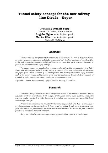
<strong>Tunnel</strong> <strong>safety</strong> <strong>concept</strong> <strong>for</strong> <strong>the</strong> <strong>new</strong> <strong>railway</strong><br />
<strong>line</strong> Diva a - <strong>Koper</strong><br />
Dr.Dipl.Ing. Rudolf Bopp<br />
Gruner, ZT GmbH, Wien; Austria<br />
Angelo Žigon, univ.dipl.inž.grad.<br />
Marko Žibert, univ.dipl.inž.grad.<br />
ELEA-iC, Ljubljana<br />
Abstract<br />
The <strong>new</strong> <strong>railway</strong> <strong>line</strong> planned between <strong>the</strong> city of Diva a and <strong>the</strong> port of <strong>Koper</strong> is characterised<br />
by a sequence of tunnels and viaducts separated only by short stretches of open <strong>line</strong>. Due<br />
to <strong>the</strong> high proportion of tunnels and <strong>the</strong> difficult access to <strong>the</strong> <strong>line</strong> particular attention must be<br />
paid to <strong>the</strong> development of a <strong>safety</strong> <strong>concept</strong>.<br />
The paper focuses on tunnel <strong>safety</strong> <strong>concept</strong> <strong>for</strong> <strong>the</strong> <strong>railway</strong> <strong>line</strong> on subsection rni Kal –<br />
<strong>Koper</strong> which is designed and will be executed as a 1st stage of <strong>the</strong> <strong>new</strong> <strong>railway</strong> <strong>line</strong>. Never<strong>the</strong>less<br />
<strong>the</strong> paper gives a short overview of <strong>the</strong> whole project. The main infrastructural <strong>safety</strong> measures<br />
such as <strong>the</strong> escape routes and <strong>the</strong> rescue areas near <strong>the</strong> portals are described. As an example of<br />
a technical <strong>safety</strong> measure <strong>the</strong> tunnel ventilation <strong>concept</strong> is presented.<br />
Keywords: <strong>Tunnel</strong>s, Safety <strong>concept</strong>, Safety in tunnels, Railway, V. corridor<br />
Povzetek<br />
Zna ilnost novega odseka železniške proge med Diva o in pristaniškim mestom <strong>Koper</strong> je<br />
zaporedje predorov in viaduktov, ki jih lo ujejo kratki odseki odprte trase. Glede na velik delež<br />
trase, ki poteka v predorih in težko dostopnost je potrebno posebno pozornost nameniti izdelavi<br />
varnostnega koncepta.<br />
Prispevek se osredoto a na predstavitev koncepta za pododsek rni Kal – <strong>Koper</strong>, ki je v<br />
terminskem planu izvedbe postavljen v 1. fazo, hkrati pa podaja kratek pregled celotnega projekta.<br />
Opisani so vsi pomembnejši infrastrukturni varnostni ukrepi kot so ubežne poti, reševalne<br />
površine in postaja na portalnih obmo jih.<br />
Kot primer tehni nega varnostnega ukrepa je predstavljena zasnova prezra evanja.<br />
Bopp, R., Žigon, A., Žibert, M.: Koncept varnosti v predorih za novo železniško progo Diva a - <strong>Koper</strong>
1 Introduction<br />
Bopp, R., Žigon, A., Žibert, M.:<br />
<strong>Tunnel</strong> <strong>safety</strong> <strong>concept</strong> <strong>for</strong> <strong>the</strong> <strong>new</strong> <strong>railway</strong> <strong>line</strong> Diva a - <strong>Koper</strong><br />
Port of <strong>Koper</strong> is one of most important<br />
centers of logistics and freight transportation<br />
in Slovenia. In year 1967 <strong>the</strong> <strong>new</strong> single track<br />
<strong>railway</strong> <strong>line</strong> was opened to connect flourishing<br />
port with middle European cities. After<br />
1990 <strong>the</strong> business growth almost tripled and<br />
with more ambitious projects ahead a need <strong>for</strong><br />
a higher capacity <strong>railway</strong> <strong>line</strong> was evident. A<br />
<strong>new</strong> single track <strong>railway</strong> <strong>line</strong> between <strong>Koper</strong><br />
and Diva a was proposed in a corridor which<br />
is a:<br />
part of V. pan-European transportation<br />
corridor Venice – Kiev and<br />
part of VI. trans-European transportation<br />
corridor Lyon – Budapest<br />
Since <strong>the</strong> negotiations with Republic of<br />
Italy over <strong>the</strong> alignment of <strong>new</strong> <strong>railway</strong><br />
section were not finished in time <strong>the</strong> client<br />
(Government of Republic of Slovenia - Ministry<br />
<strong>for</strong> Transportation) decided to move<br />
ahead with first stage from <strong>Koper</strong> to rni Kal<br />
which probably will not be part of <strong>the</strong> main<br />
corridor.<br />
This <strong>new</strong> high capacity <strong>railway</strong> <strong>line</strong> will<br />
run predominantly through tunnels. As <strong>safety</strong><br />
measures may greatly influence <strong>the</strong> tunnel<br />
design, tunnel <strong>safety</strong> aspects must be considered<br />
in an early phase of <strong>the</strong> project and some<br />
fundamental decisions have to be taken. As<br />
<strong>the</strong>se decisions influence not only <strong>the</strong> <strong>safety</strong><br />
but have also wide impacts on <strong>the</strong> construction<br />
and operation costs of <strong>the</strong> <strong>new</strong> <strong>railway</strong><br />
<strong>line</strong> a close examination is necessary.<br />
Figure 1: Location of <strong>the</strong> <strong>railway</strong> <strong>line</strong> regarding pan-european and trans-european corridors<br />
The paper gives first some in<strong>for</strong>mation<br />
on <strong>the</strong> relevant guide<strong>line</strong>s <strong>for</strong> tunnel <strong>safety</strong><br />
and <strong>the</strong> approach <strong>for</strong> <strong>the</strong> development of a<br />
tunnel <strong>safety</strong> <strong>concept</strong>. In a second part <strong>the</strong><br />
most important <strong>safety</strong> measures which have<br />
been decided <strong>for</strong> <strong>the</strong> Diva a - <strong>Koper</strong> project<br />
are described.<br />
2 Project overview<br />
2.1 General description<br />
In order to cope with immediate ascent<br />
of <strong>the</strong> terrain in <strong>Koper</strong> hinterland <strong>the</strong> alignment<br />
of <strong>the</strong> high capacity <strong>railway</strong> <strong>line</strong> travels<br />
ra<strong>the</strong>r through tunnels in constant gradient<br />
than in many twists on open section like <strong>the</strong><br />
existing <strong>line</strong>.<br />
The whole section of <strong>railway</strong> <strong>line</strong> alignment<br />
from <strong>Koper</strong> to Diva a is characterized<br />
by two distinctive subsections (see Figure 2).<br />
The first section with 6 tunnels and two long<br />
viaducts leads from <strong>Koper</strong> to rni Kal with a<br />
length of 12.135 km where alignment gains<br />
height traveling just under <strong>the</strong> surface on <strong>the</strong><br />
slopes of Tinjan hill in big circular section<br />
and ends with crossing Osp Vally with long<br />
viaduct. The second section from rni Kal to<br />
Diva a with a length of 15.061 km travels<br />
through 2 deep long straight tunnels in karstic<br />
region. Only <strong>the</strong> first section will be described<br />
in fur<strong>the</strong>r text.<br />
More than 7.5 km out of 12.1 km of <strong>the</strong><br />
<strong>railway</strong> <strong>line</strong> from <strong>Koper</strong> to rni Kal travels<br />
through tunnels. The distance between portals<br />
of consecutive tunnels in <strong>the</strong> upper part of this<br />
section is very short. <strong>Tunnel</strong>s T3 to T7 must<br />
<strong>the</strong>re<strong>for</strong>e be considered as one long tunnel<br />
(see also Table 1)<br />
10. SLOVENSKI KONGRES O CESTAH IN PROMETU, Portorož, 20. – 22. oktobra 2010
Bopp, R., Žigon, A., Žibert, M.:<br />
<strong>Tunnel</strong> <strong>safety</strong> <strong>concept</strong> <strong>for</strong> <strong>the</strong> <strong>new</strong> <strong>railway</strong> <strong>line</strong> Diva a - <strong>Koper</strong><br />
Figure 2: The general layout of <strong>the</strong> <strong>railway</strong> alignment<br />
Figure 3: The longitudinal profile of <strong>the</strong> <strong>railway</strong> <strong>line</strong><br />
Table 1: Description of <strong>the</strong> tunnels on subsection <strong>Koper</strong> – rni Kal<br />
<strong>Tunnel</strong> Length <strong>Tunnel</strong> Set Start Ch. End Ch. Length of<br />
tunnel set<br />
T3 330 m<br />
T4 1947 m<br />
T5 115 m 1 16+760,000 21+020,000 4360 m<br />
T6 335 m<br />
T7 1150 m<br />
T8 3760 m 2 22+280,000 26+040,000 3760 m<br />
2.2 Description of a typical<br />
tunnel<br />
Typical tunnel on <strong>the</strong> <strong>new</strong> <strong>railway</strong> <strong>line</strong> is<br />
a single track, single tube NATM tunnel<br />
consisting of primary shotcrete lining, waterproof<br />
layer and cast in place concrete lining.<br />
Typical inner dimension of horseshoe like<br />
<strong>for</strong>m of normal cross section is width/height<br />
=6’7m/7’0m, designed around demanded<br />
modified GC train clearance profile (see<br />
Figure 4). With a possible future second tube<br />
in mind <strong>the</strong> cross section is designed as<br />
symmetrical thus track (width=3’40m) is<br />
positioned in <strong>the</strong> axis of <strong>the</strong> tunnel with raised<br />
emergency walkway (width=1’65m) located<br />
on both sides. Bellow walkways <strong>the</strong> space <strong>for</strong><br />
10. SLOVENSKI KONGRES O CESTAH IN PROMETU, Portorož, 20. – 22. oktobra 2010
Bopp, R., Žigon, A., Žibert, M.:<br />
<strong>Tunnel</strong> <strong>safety</strong> <strong>concept</strong> <strong>for</strong> <strong>the</strong> <strong>new</strong> <strong>railway</strong> <strong>line</strong> Diva a - <strong>Koper</strong><br />
supply and telecommunication cabling is<br />
provided.<br />
The track structure is designed as a slab<br />
track system sitting on tunnel invert concrete.<br />
Table 2: Overview of traffic characteristics<br />
2.3 Operation of <strong>the</strong> <strong>new</strong> <strong>line</strong><br />
The <strong>railway</strong> <strong>line</strong> will be used mainly by<br />
freight trains climbing <strong>the</strong> ascent from <strong>the</strong><br />
port of <strong>Koper</strong> towards Diva a. Never<strong>the</strong>less<br />
<strong>the</strong> <strong>railway</strong> <strong>line</strong> is designed <strong>for</strong> both freight<br />
and passenger trains (see Table 2) in both<br />
directions driving in bundles of 3 to 5 trains.<br />
Type Number Length of train<br />
(max./average)<br />
Vmax Notes<br />
IC/EC 3 pairs of trains/day 400 m/250 m 160 km/h<br />
Pendolino 2 pairs of trains/day 82 m/82 m 160 km/h<br />
Freight trains direction 45 (fully loaded) or 750 m/500 m 120 km/h Ro-La<br />
to <strong>Koper</strong><br />
57 (dynamic ut. )<br />
Freight trains direction 50 (fully loaded) or 750 m/500 m 80 km/h Ro-La<br />
to Diva a 63 (dynamic ut. )<br />
In accordance with TSI RST HS only<br />
trains category B shall be used in passenger<br />
traffic on <strong>the</strong> <strong>new</strong> <strong>railway</strong> <strong>line</strong>. This category<br />
demands that in case of fire <strong>the</strong> train is capable<br />
of driving at least 80km/h <strong>for</strong> next 15<br />
minutes ignoring emergency brakes and<br />
maintaining means of communication.<br />
Currently a 3kV DC (direct current) supply<br />
catenary system is planned. In future a<br />
25kV 50Hz AC system is <strong>for</strong>eseen.<br />
Figure 4: Typical NATM tunnel cross section<br />
3 Guide<strong>line</strong>s<br />
3.1 European and national<br />
guide<strong>line</strong>s<br />
The main risks in <strong>railway</strong> tunnels are<br />
fire, collision and derailment. As a fire in a<br />
passenger train is a major and specific hazard<br />
in tunnels with potentially catastrophic consequences,<br />
discussions about tunnel <strong>safety</strong><br />
10. SLOVENSKI KONGRES O CESTAH IN PROMETU, Portorož, 20. – 22. oktobra 2010
Bopp, R., Žigon, A., Žibert, M.:<br />
<strong>Tunnel</strong> <strong>safety</strong> <strong>concept</strong> <strong>for</strong> <strong>the</strong> <strong>new</strong> <strong>railway</strong> <strong>line</strong> Diva a - <strong>Koper</strong><br />
often concentrate on this type of incident.<br />
However this limited perception must be<br />
abandoned when a <strong>safety</strong> <strong>concept</strong> <strong>for</strong> a <strong>railway</strong><br />
<strong>line</strong> as <strong>the</strong> Diva a -<strong>Koper</strong> <strong>line</strong> is developed.<br />
The elaboration of a tunnel <strong>safety</strong> <strong>concept</strong><br />
is a quite complex task where an important<br />
number of aspects and subsystems must<br />
be considered. There are however only few<br />
guide<strong>line</strong>s on <strong>safety</strong> in <strong>railway</strong> tunnels which<br />
can be consulted. The most important are <strong>the</strong><br />
technical specification of interoperability<br />
relating to ‘<strong>safety</strong> in <strong>railway</strong> tunnels’ in <strong>the</strong><br />
trans-European conventional and high-speed<br />
rail system, <strong>the</strong> so called TSI SRT 0. These<br />
relatively <strong>new</strong> specifications define <strong>for</strong> a first<br />
time a minimal <strong>safety</strong> standard <strong>for</strong> <strong>railway</strong><br />
tunnels in Europe. However TSI SRT specifies<br />
only few mandatory <strong>safety</strong> measures.<br />
In addition to <strong>the</strong> <strong>safety</strong> measures specified<br />
in <strong>the</strong> TSI SRT, <strong>the</strong> guide<strong>line</strong>s of <strong>the</strong> UIC<br />
Codex 779-9 0 concerning tunnel <strong>safety</strong><br />
should be considered. The UIC document<br />
gives a good overview over a more general<br />
set of possible <strong>safety</strong> measures and provides<br />
additional in<strong>for</strong>mation concerning <strong>the</strong> efficiency<br />
of different <strong>safety</strong> measures.<br />
Along with <strong>the</strong> European guide<strong>line</strong>s<br />
<strong>the</strong>re are a number of national guide<strong>line</strong>s as<br />
<strong>for</strong> example <strong>the</strong> German EBA guide<strong>line</strong> 0 or<br />
<strong>the</strong> Swiss guide<strong>line</strong> SIA 197 0, 0. In Austria<br />
<strong>the</strong> guide<strong>line</strong> of <strong>the</strong> national fire fighting<br />
association has to be considered 0. These<br />
national guide<strong>line</strong>s ask to some extent <strong>for</strong><br />
additional <strong>safety</strong> measures and <strong>the</strong>y often do<br />
specify <strong>the</strong> needed measures in more detail.<br />
This may lead to a different set of <strong>safety</strong><br />
measures when different national guide<strong>line</strong>s<br />
are used (see examples in chapter 3.3).<br />
In <strong>the</strong> absence of national guide<strong>line</strong>s and<br />
lack of most recent national experience in<br />
<strong>railway</strong> tunnel <strong>safety</strong>, as it is <strong>the</strong> case in<br />
Slovenia, <strong>the</strong> development of a specific<br />
<strong>railway</strong> tunnel <strong>safety</strong> <strong>concept</strong> is <strong>the</strong>re<strong>for</strong>e a<br />
long process which has to involve a various<br />
authorities (see chapter 4.2).<br />
3.2 Application of guide<strong>line</strong>s<br />
In <strong>the</strong> application of <strong>the</strong> different guide<strong>line</strong>s<br />
<strong>the</strong> following problems may appear:<br />
National guide<strong>line</strong>s are normally<br />
stricter than <strong>the</strong> regulations of <strong>the</strong> TSI<br />
SRT.<br />
When comparing different national<br />
guide<strong>line</strong>s different <strong>safety</strong> measures<br />
may result.<br />
3.2.1 Comparison between TSI<br />
SRT and national guide<strong>line</strong>s<br />
The most important infrastructural <strong>safety</strong><br />
measures specified in <strong>the</strong> TSI SRT are:<br />
Escape distance: The maximum distance<br />
of cross passages (in double bore tunnels or in<br />
tunnels with a parallel service and <strong>safety</strong><br />
tunnel) or distance of emergency exits in<br />
single bore tunnels is stipulated in <strong>the</strong> TSI<br />
SRT (maximum 500 m <strong>for</strong> tunnels with a<br />
parallel tube or maximum 1000 m <strong>for</strong> a<br />
double track tunnel).<br />
Escape walkways: Lateral walkways<br />
inside <strong>the</strong> tunnel with a minimal width<br />
of 0.7 m must be provided.<br />
Rescue areas at tunnel portals: In <strong>the</strong><br />
vicinity of <strong>the</strong> tunnel portals enough<br />
space <strong>for</strong> <strong>the</strong> deployment of <strong>the</strong> rescue<br />
services is needed. The TSI SRT defines<br />
a minimal area of 500 m 2 .<br />
The fact that some of <strong>the</strong> very long<br />
double bore tunnels planned or built in<br />
<strong>the</strong> last years, have considerably lower<br />
distances between cross passages (see<br />
table 3) shows that in <strong>the</strong> application of<br />
<strong>the</strong> TSI SRT and national guide<strong>line</strong>s<br />
different solutions may result. This is<br />
not only true <strong>for</strong> <strong>the</strong> distance of cross<br />
passages but also <strong>for</strong> <strong>the</strong> width of <strong>the</strong><br />
escape walkway which is normally<br />
bigger than 0.7 m or <strong>the</strong> rescue areas at<br />
portals which are normally considerably<br />
larger than 500 m 2 as stipulated in<br />
<strong>the</strong> TSI SRT.<br />
Table 3: Distances of cross passages in long <strong>railway</strong> tunnels<br />
<strong>Tunnel</strong> Length Cross passages Special features<br />
Channel <strong>Tunnel</strong> 50.5 km 375 m lorry transport<br />
Lötschberg Base <strong>Tunnel</strong> 34.6 km 333 m underground emergency station<br />
Tunel de Guardarrama 28.4 km 250 m<br />
Great Belt <strong>Tunnel</strong> 8.0 km 250 m underwater tunnel<br />
10. SLOVENSKI KONGRES O CESTAH IN PROMETU, Portorož, 20. – 22. oktobra 2010
3.2.2 Comparison between national<br />
guide<strong>line</strong>s<br />
Consulting different national guide<strong>line</strong>s<br />
may lead to contradictory recommendations<br />
as <strong>the</strong> following examples show:<br />
Water supply <strong>for</strong> fire fighting: In Germany<br />
dry water pipes in all tunnels<br />
longer than 500 m are mandatory<br />
whereas in Switzerland normally rescue<br />
trains (mobile water supply) are<br />
used and no fixed water pipes are <strong>for</strong>eseen<br />
in <strong>railway</strong> tunnels. In Austria permanently<br />
filled or dry pipes are demanded.<br />
However in very long tunnels<br />
as <strong>the</strong> 32.8 km long Koralmtunnel 0 or<br />
<strong>the</strong> 27 km long Semmering-Base <strong>Tunnel</strong><br />
0 <strong>the</strong> water is brought into <strong>the</strong> tunnel<br />
by a rescue train and a fixed water<br />
supply system is planned only in <strong>the</strong><br />
underground emergency station.<br />
Ventilation: Ano<strong>the</strong>r example is <strong>the</strong><br />
ventilation of cross passages which<br />
connect two parallel tunnel tubes. Ac-<br />
Professional<br />
Qualifications<br />
Maintenance<br />
Rules<br />
Operation<br />
Rules<br />
Health &<br />
Safety<br />
Conditions<br />
<strong>Tunnel</strong><br />
Safety<br />
Bopp, R., Žigon, A., Žibert, M.: Koncept varnosti v predorih za novo železniško progo Diva a - <strong>Koper</strong><br />
cording to <strong>the</strong> German EBA guide<strong>line</strong><br />
airlocks without any mechanical installation<br />
to prevent a propagation of<br />
smoke to <strong>the</strong> parallel tunnel tube (safe<br />
area) are possible, whereas in Austria a<br />
mechanically generated overpressure is<br />
requested.<br />
4 Approach to develop a<br />
<strong>safety</strong> <strong>concept</strong> <strong>for</strong> a<br />
<strong>railway</strong> tunnel<br />
4.1 Subsystems<br />
Although in tunnel projects major focus<br />
is put on infrastructural <strong>safety</strong> measures it has<br />
to be pointed out that tunnel <strong>safety</strong> depends<br />
not only on infrastructural measures but on a<br />
bigger number of subsystems. Figure 5 gives<br />
an overview over <strong>the</strong>se subsystems. All of<br />
<strong>the</strong>m are equally important and have to be<br />
considered in <strong>the</strong> development of a tunnel<br />
<strong>safety</strong> <strong>concept</strong>.<br />
Rolling<br />
Stock<br />
Infrastructure<br />
Energy<br />
Figure 5: Subsystems relevant <strong>for</strong> <strong>railway</strong> tunnel <strong>safety</strong> according to 0<br />
4.2 Basic principles<br />
Although <strong>the</strong>re is no generally accepted<br />
state of <strong>the</strong> art <strong>for</strong> tunnel <strong>safety</strong> some generally<br />
agreed principles do exist. So <strong>the</strong> design<br />
of a tunnel must allow <strong>the</strong> self-rescue and<br />
evacuation of train passengers and staff.<br />
Fur<strong>the</strong>rmore provisions <strong>for</strong> <strong>the</strong> rescue services<br />
to rescue people in <strong>the</strong> event of an<br />
incident in a tunnel shall be provided. Appropriate<br />
<strong>safety</strong> measures should be considered<br />
when a tunnel <strong>safety</strong> <strong>concept</strong> is developed.
Bopp, R., Žigon, A., Žibert, M.:<br />
<strong>Tunnel</strong> <strong>safety</strong> <strong>concept</strong> <strong>for</strong> <strong>the</strong> <strong>new</strong> <strong>railway</strong> <strong>line</strong> Diva a - <strong>Koper</strong><br />
According to 0 and 0 <strong>the</strong>re are <strong>the</strong> 4 following<br />
categories of measures which can be<br />
discerned:<br />
Prevention of incidents,<br />
Mitigation of impact of accidents,<br />
Facilitation of escape,<br />
Facilitation of rescue.<br />
The order in which <strong>the</strong>se categories are<br />
listed reflects <strong>the</strong>ir decreasing effectiveness to<br />
Safe side<br />
Risk in tunnels<br />
Prevention<br />
A <strong>safety</strong> <strong>concept</strong> generally consists of a<br />
combination of infrastructure (civil and<br />
technical), operations and rolling stock measures,<br />
which should be combined in a manner<br />
to achieve an optimised <strong>concept</strong>. The definition<br />
of specific <strong>safety</strong> measures in a project<br />
should be based on an assessment of <strong>the</strong> risk<br />
(risk based <strong>safety</strong> <strong>concept</strong>).<br />
4.3 Safety management<br />
group<br />
Mitigation<br />
There is not only a big number of subsystems<br />
which must be considered in <strong>the</strong><br />
elaboration of a <strong>safety</strong> <strong>concept</strong>, but also <strong>the</strong><br />
different stakeholders involved in <strong>the</strong> planning<br />
process (national authorities, <strong>the</strong> owner,<br />
<strong>the</strong> designer of <strong>the</strong> tunnel and <strong>the</strong> technical<br />
installations, contractor(s), operator, emergency<br />
services as fire fighters). It is <strong>the</strong>re<strong>for</strong>e<br />
recommended that a <strong>safety</strong> <strong>concept</strong> is developed<br />
in a <strong>safety</strong> management group 0 which<br />
goes along with <strong>the</strong> project over all project<br />
phases. The <strong>safety</strong> management group will<br />
normally be a "living structure/organism"<br />
which has to adapt to <strong>the</strong> changing needs<br />
during <strong>the</strong> different phases of <strong>the</strong> project.<br />
Figure 6: Hierarchy of <strong>safety</strong> measures<br />
reduce <strong>the</strong> risk in a <strong>railway</strong> tunnel (see Figure<br />
6). It is important to note that measures preventing<br />
an incident in <strong>the</strong> tunnel (e.g. emergency<br />
brake neutralisation during a tunnel<br />
passage) are much more effective than measures<br />
which improve <strong>the</strong> self rescue (facilitation<br />
of escape) of passengers or measures<br />
which support <strong>the</strong> rescue services (facilitation<br />
of rescue). The strength of <strong>railway</strong>s lies in <strong>the</strong><br />
prevention of accidents.<br />
Evacuation<br />
Rescue<br />
Residual<br />
risk<br />
One of <strong>the</strong> very important tasks of <strong>the</strong><br />
<strong>safety</strong> management group is <strong>the</strong> definition of<br />
specific (quantitative or qualitative) <strong>safety</strong><br />
goals. The instruments to check <strong>the</strong> achievement<br />
of <strong>the</strong>se <strong>safety</strong> goals and <strong>the</strong> methods to<br />
assess <strong>the</strong> (residual) risk should be defined.<br />
Fur<strong>the</strong>rmore <strong>the</strong> key decisions should be<br />
systematically recorded and <strong>the</strong> contents of<br />
<strong>the</strong> <strong>safety</strong> documents <strong>for</strong> <strong>the</strong> procedure of<br />
approval by <strong>the</strong> authorities as well as <strong>the</strong><br />
documents, which will be used in <strong>the</strong> operation<br />
phase, should be defined in an early stage<br />
of <strong>the</strong> project.<br />
5 Key elements of <strong>the</strong><br />
<strong>safety</strong> <strong>concept</strong> rni Kal<br />
- <strong>Koper</strong><br />
5.1 Infrastructural <strong>safety</strong><br />
measures<br />
In <strong>the</strong> early phase of <strong>the</strong> project <strong>the</strong> infrastructural<br />
measures had to be defined as a<br />
basis <strong>for</strong> <strong>the</strong> planning of <strong>the</strong> tunnels. The<br />
most important measures are:<br />
10. SLOVENSKI KONGRES O CESTAH IN PROMETU, Portorož, 20. – 22. oktobra 2010
Bopp, R., Žigon, A., Žibert, M.:<br />
<strong>Tunnel</strong> <strong>safety</strong> <strong>concept</strong> <strong>for</strong> <strong>the</strong> <strong>new</strong> <strong>railway</strong> <strong>line</strong> Diva a - <strong>Koper</strong><br />
5.1.1 <strong>Tunnel</strong> system<br />
Single track tunnels: All tunnels are<br />
single track, so that <strong>the</strong>re are no<br />
switches in <strong>the</strong> tunnels. The risks associate<br />
with train crossings and derailment<br />
are thus reduced.<br />
Escape routes: Special lateral escape<br />
galleries in longer tunnels (T4, T7) will<br />
be built. The maximum distance between<br />
to escape galleries is 660 m. For<br />
<strong>the</strong> longest tunnel (T8) a parallel <strong>safety</strong><br />
tunnel with cross passages to <strong>the</strong> <strong>railway</strong><br />
tunnel every 500 m is planned. In<br />
<strong>the</strong> <strong>railway</strong> tunnels on both sides a lateral<br />
walkway is available. The width of<br />
<strong>the</strong> lateral walkway is 1.65 m and <strong>the</strong><br />
walkway on <strong>the</strong> side which leads to <strong>the</strong><br />
escape galleries / cross passages is<br />
equipped with a handrail.<br />
Fire protection <strong>for</strong> structures: The<br />
zones where tunnels cross critical infrastructures<br />
as <strong>the</strong> highway <strong>Koper</strong> -<br />
Ljubljana with low overburden special<br />
rein<strong>for</strong>cement of <strong>the</strong> tunnel structure is<br />
<strong>for</strong>eseen to guarantee <strong>the</strong> stability of<br />
<strong>the</strong> tunnel <strong>for</strong> a sufficient time in <strong>the</strong><br />
case of a fire in <strong>the</strong> tunnel.<br />
Collection of water and liquids: In addition<br />
to <strong>the</strong> drainage system to collect<br />
<strong>the</strong> rock water, a separate de-watering<br />
system is <strong>for</strong>eseen in <strong>the</strong> tunnels to<br />
drain <strong>for</strong>ge water or toxic liquids in<br />
case of a spillage of dangerous goods.<br />
These liquids are collected by a separate<br />
drainage tube which is equipped<br />
with siphons in regular intervals and<br />
which is connected to a retention basin<br />
at <strong>the</strong> lower tunnel portal.<br />
5.1.2 Emergency stop area<br />
The probability that a burning train can't<br />
reach <strong>the</strong> portal (safe area) increases with<br />
increasing tunnel length. There<strong>for</strong>e, according<br />
to TSI SRT "appropriate provisions must be<br />
laid down to take account of <strong>the</strong> particular<br />
<strong>safety</strong> conditions in very long tunnels". As <strong>the</strong><br />
Diva a - <strong>Koper</strong> <strong>line</strong> consists of a continuous<br />
succession of tunnels and viaducts <strong>the</strong>re is no<br />
natural place, where a train could be stopped<br />
and evacuated in <strong>the</strong> case of a fire. The situation<br />
is thus comparable with a very long<br />
tunnel.<br />
In <strong>the</strong> case of a train fire a modern passenger<br />
train should maintain its movement<br />
capability <strong>for</strong> 15 minutes 0. Assuming a train<br />
speed of 80 km/h a train can thus travel a<br />
distance of about 20 km. There<strong>for</strong>e in tunnels<br />
which are significantly longer than 20 km<br />
normally an emergency station is <strong>for</strong>eseen,<br />
where a tunnel can be stopped and evacuated<br />
0, 0. This <strong>safety</strong> measure which can drastically<br />
reduce <strong>the</strong> severity of a train fire is also<br />
implemented in <strong>the</strong> Diva a - <strong>Koper</strong> project.<br />
At km 16.1, which is approximately in<br />
<strong>the</strong> middle of <strong>the</strong> section with <strong>the</strong> 8 tunnels an<br />
emergency stop area is planned at <strong>the</strong> lower<br />
portal of <strong>Tunnel</strong> T2. A plat<strong>for</strong>m with a length<br />
of 400 m allows a fast and safe evacuation of<br />
a train. Due to <strong>the</strong> limited space a part of <strong>the</strong><br />
plat<strong>for</strong>m will be located on <strong>the</strong> viaduct. The<br />
area is equipped with lighting, communications<br />
facilities, video control, etc and can be<br />
accessed by road vehicles.<br />
5.1.3 Portal areas and access<br />
to tunnels<br />
The roads which are built <strong>for</strong> <strong>the</strong> construction<br />
of <strong>the</strong> tunnels will serve as access<br />
roads to <strong>the</strong> tunnel in <strong>the</strong> operation phase.<br />
Despite <strong>the</strong> mountainous area each tunnel<br />
portal can be reached by road vehicles. Totally<br />
6 portal areas with a surface of minimum<br />
1500 m 2 and 7 portal places with a surface of<br />
minimum 500 m 2 are available <strong>for</strong> emergency<br />
services.<br />
The slab track is not trafficable by road<br />
vehicles. Access into <strong>the</strong> tunnel is ensured by<br />
two way vehicles (road - rail) of <strong>the</strong> fire<br />
fighters. Additionally rolling pallets <strong>for</strong> <strong>the</strong><br />
transport of injured passengers and material<br />
will be available at <strong>the</strong> portals of <strong>the</strong> tunnels<br />
and <strong>the</strong> escape galleries.<br />
10. SLOVENSKI KONGRES O CESTAH IN PROMETU, Portorož, 20. – 22. oktobra 2010
Bopp, R., Žigon, A., Žibert, M.:<br />
<strong>Tunnel</strong> <strong>safety</strong> <strong>concept</strong> <strong>for</strong> <strong>the</strong> <strong>new</strong> <strong>railway</strong> <strong>line</strong> Diva a - <strong>Koper</strong><br />
Figure 5: Typical section of layout <strong>for</strong> <strong>safety</strong> <strong>concept</strong> showing rescue areas, equipment provided, emergency<br />
routes <strong>for</strong> rescuers and time prognoses,….<br />
5.2 Technical <strong>safety</strong> measures<br />
Beside <strong>the</strong> infrastructural <strong>safety</strong> measures<br />
a big number of technical <strong>safety</strong> measures<br />
are planned. The most important are<br />
given below:<br />
5.2.1 Ventilation<br />
Whereas longer road tunnels are generally<br />
equipped with a mechanical ventilation<br />
system, <strong>railway</strong> tunnels normally do not have<br />
a mechanical ventilation system because <strong>the</strong>re<br />
is no exhaust from combustion engines which<br />
has to be removed from <strong>the</strong> tunnel. If <strong>railway</strong><br />
tunnels are equipped with ventilation system,<br />
<strong>the</strong> primary goal is to guarantee smoke free<br />
areas (a safe area according to TSI SRT). This<br />
is normally achieved by a positive pressure<br />
compared to <strong>the</strong> incident tube. It has to be<br />
noted however, that it is not state of <strong>the</strong> art to<br />
use <strong>the</strong> ventilation in rail tunnels to control<br />
<strong>the</strong> smoke movement in <strong>the</strong> incident tunnel<br />
itself.<br />
In <strong>the</strong> Crni-Kal section of Diva a - <strong>Koper</strong><br />
project <strong>the</strong> following ventilation system<br />
are planned:<br />
Ventilation of service tunnel (T8): The<br />
3.8 km long tunnel T8 has a parallel<br />
service tunnel with ventilation buildings<br />
on both sides. A mechanical ventilation<br />
system is needed to remove <strong>the</strong><br />
waste heat of <strong>the</strong> technical equipment<br />
which is placed in technical rooms<br />
which are located in <strong>the</strong> cross passages.<br />
Additionally <strong>the</strong> ventilation system<br />
must guarantee a sufficient airflow<br />
through open escape doors in <strong>the</strong> case<br />
of a fire.<br />
The fans, which are located at both portals<br />
of <strong>the</strong> service tunnel, bring air into<br />
<strong>the</strong> service tunnel to generate an overpressure<br />
to <strong>the</strong> <strong>railway</strong> tunnel. On both<br />
sides 2 fans are <strong>for</strong>eseen, so that even<br />
in <strong>the</strong> case of one fan failing, still more<br />
than 75% of <strong>the</strong> maximum airflow can<br />
be delivered. This partly redundancy is<br />
important because <strong>the</strong> waste heat has to<br />
be removed permanently from <strong>the</strong> tunnel<br />
to guarantee a safe operation of <strong>the</strong><br />
technical equipment.<br />
In each of <strong>the</strong> 7 cross passages a door is<br />
<strong>for</strong>eseen separating <strong>the</strong> <strong>railway</strong> tunnel<br />
from <strong>the</strong> safe area. To maintain <strong>the</strong><br />
overpressure in <strong>the</strong> parallel service tunnel<br />
during self rescue and access of<br />
rescue services both portals are<br />
equipped with an airlock.<br />
Ventilation of escape galleries (T4,<br />
T7): As <strong>the</strong>re is no need to remove<br />
waste heat from technical installation in<br />
<strong>the</strong> escape galleries in normal operation<br />
a simpler ventilation system is possible.<br />
The escape galleries of tunnels T4 and<br />
T7 are equipped with an air lock which<br />
is situated at <strong>the</strong> exit of <strong>the</strong> escape gallery.<br />
At <strong>the</strong> o<strong>the</strong>r end of <strong>the</strong> escape gallery<br />
an escape doors separates <strong>the</strong> safe<br />
area from <strong>the</strong> <strong>railway</strong> tunnel. Above <strong>the</strong><br />
airlock a single fan is <strong>for</strong>eseen which is<br />
able to provide an airflow through <strong>the</strong><br />
10. SLOVENSKI KONGRES O CESTAH IN PROMETU, Portorož, 20. – 22. oktobra 2010
Bopp, R., Žigon, A., Žibert, M.:<br />
<strong>Tunnel</strong> <strong>safety</strong> <strong>concept</strong> <strong>for</strong> <strong>the</strong> <strong>new</strong> <strong>railway</strong> <strong>line</strong> Diva a - <strong>Koper</strong><br />
escape door which is high enough to<br />
prevent smoke penetrating in <strong>the</strong> escape<br />
gallery.<br />
5.2.3 Measures to facilitate rescue<br />
Table 4: Safety measures to facilitate self rescue<br />
5.2.2 Water <strong>for</strong> fire fighting<br />
All tunnels are equipped with hydrants at<br />
a distance of 125 m. The water pipe, which is<br />
permanently filled, is supplied by 3 basins<br />
with a volume of 200 m 3 each. A pressure<br />
between 6 and 12 bar is assure at all points<br />
and 800 l/min can be supplied.<br />
Measure Remarks<br />
Emergency lighting Illuminated walkway (minimum 1 lux) and escape<br />
galleries, brig<strong>the</strong>r illumination of escape doors<br />
Escape signage illuminated signs at a distance of 50 m on escape walkway,<br />
reflecting signs between <strong>the</strong> illuminated signs<br />
Table 5: Safety measures to facilitate rescue<br />
Measure Remarks<br />
Segmentation of overhead <strong>line</strong> segment < 5 km (details still to be defined in a later<br />
project phase)<br />
Earthling devices <strong>for</strong> overhead <strong>line</strong> details still to be defined<br />
Electricity supply 230V / 400V power sockets at distance of 125 m<br />
Communication<br />
radio <strong>for</strong> emergency services<br />
2 Way vehicle to facilitate access to based in <strong>Koper</strong><br />
tunnel<br />
Rolling pallets at portals of main tunnels and at portal of escape galleries<br />
5.3 Operational <strong>safety</strong> measures<br />
and train <strong>safety</strong><br />
Beside <strong>the</strong> infrastructural and technical<br />
<strong>safety</strong> measures also <strong>the</strong> trains and <strong>the</strong> operational<br />
procedures do have an important impact<br />
on <strong>the</strong> <strong>safety</strong> level. Passenger trains of<br />
category B will be used. Actually <strong>the</strong>re are no<br />
restrictions <strong>for</strong> freight trains and/or transportation<br />
of dangerous goods <strong>for</strong>eseen. Fur<strong>the</strong>r<br />
studies, especially on <strong>the</strong> transportation of<br />
dangerous good should be undertaken in <strong>the</strong><br />
next project phase.<br />
In <strong>the</strong> case of an emergency situation fast<br />
operational action is needed. Only few decisions<br />
and relatively simple operational measures<br />
are necessary in <strong>the</strong> case of a train fire.<br />
The most important operational measures in<br />
an emergency situation are:<br />
Trains following <strong>the</strong> emergency train<br />
are stop immediately. Whenever possible<br />
it should be avoided that two trains<br />
are in a tunnel.<br />
Trains in front of <strong>the</strong> emergency train<br />
continue <strong>the</strong>ir journey.<br />
The emergency train itself should not<br />
stop inside a tunnel. The train tries to<br />
reach <strong>the</strong> emergency stop area resp. to<br />
<strong>the</strong> end of <strong>the</strong> <strong>line</strong>.<br />
The detail operational procedures in a<br />
case of an accident will be specified in a later<br />
phase of <strong>the</strong> project.<br />
References<br />
TSI SRT, "Safety in <strong>railway</strong> tunnels in <strong>the</strong> trans-<br />
European conventional and high-speed rail<br />
system", 2008/163/EC<br />
UIC leaflet 779-9, Safety in Railway <strong>Tunnel</strong>s,<br />
August 2003<br />
An<strong>for</strong>derungen des Brand- und Katastrophenschutzes<br />
an den Bau und den Betrieb von Eisenbahntunneln,<br />
Eisenbahn Bundesamt,<br />
1.07.2008<br />
SN 505 197, SIA 197, Projektierung <strong>Tunnel</strong>,<br />
Grundlagen, SIA Zürich 2004<br />
SN 505 197/1, SIA 197-1, Projektierung <strong>Tunnel</strong>,<br />
Bahntunnel, SIA Zürich 2004<br />
ÖBFV-RL A12, "Bau und Betrieb von neuen<br />
Eisenbahntunnel bei Haupt- und Nebenbahnen,<br />
An<strong>for</strong>derungen des Brand- und Katastrophenschutzes"<br />
Richtlinie, Österreichischer Bundesfeuerwehrverband,<br />
Ausgabe 2000<br />
10. SLOVENSKI KONGRES O CESTAH IN PROMETU, Portorož, 20. – 22. oktobra 2010
Bopp, R., Žigon, A., Žibert, M.:<br />
<strong>Tunnel</strong> <strong>safety</strong> <strong>concept</strong> <strong>for</strong> <strong>the</strong> <strong>new</strong> <strong>railway</strong> <strong>line</strong> Diva a - <strong>Koper</strong><br />
Bopp, Burghart, Harer, Koinig, Neumann - "Incident<br />
management in a very long <strong>railway</strong> tunnel",<br />
3rd International Symposium on <strong>Tunnel</strong><br />
Safety and Security, 12-14 March, Stockholm,<br />
Sweden<br />
Bopp, Langer, Neumann, Wagner, The ventilation<br />
and tunnel <strong>safety</strong> <strong>concept</strong> <strong>for</strong> <strong>the</strong> New Semmering<br />
Base <strong>Tunnel</strong>, Südbahntagung, Leoben<br />
2009<br />
Long <strong>Tunnel</strong>s at great depth, ITA working Group<br />
no 17, ITA Report No 004, April 2010<br />
10. SLOVENSKI KONGRES O CESTAH IN PROMETU, Portorož, 20. – 22. oktobra 2010