Active markers for outdoor and indoor robot localization
Active markers for outdoor and indoor robot localization
Active markers for outdoor and indoor robot localization

Create successful ePaper yourself
Turn your PDF publications into a flip-book with our unique Google optimized e-Paper software.
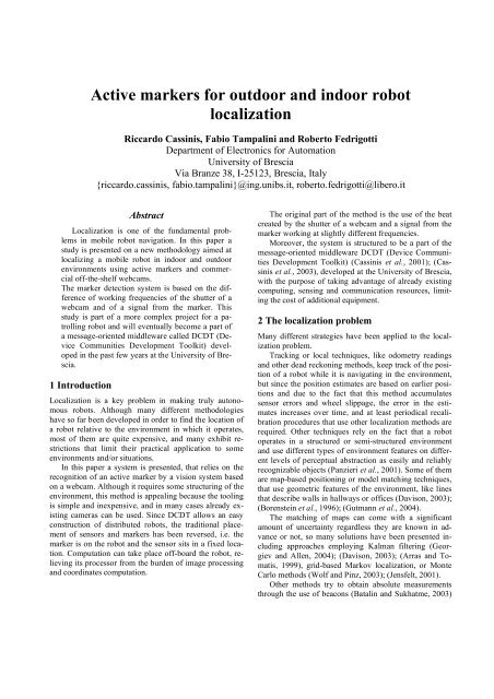
<strong>Active</strong> <strong>markers</strong> <strong>for</strong> <strong>outdoor</strong> <strong>and</strong> <strong>indoor</strong> <strong>robot</strong><br />
<strong>localization</strong><br />
Riccardo Cassinis, Fabio Tampalini <strong>and</strong> Roberto Fedrigotti<br />
Department of Electronics <strong>for</strong> Automation<br />
University of Brescia<br />
Via Branze 38, I-25123, Brescia, Italy<br />
{riccardo.cassinis, fabio.tampalini}@ing.unibs.it, roberto.fedrigotti@libero.it<br />
Abstract<br />
Localization is one of the fundamental problems<br />
in mobile <strong>robot</strong> navigation. In this paper a<br />
study is presented on a new methodology aimed at<br />
localizing a mobile <strong>robot</strong> in <strong>indoor</strong> <strong>and</strong> <strong>outdoor</strong><br />
environments using active <strong>markers</strong> <strong>and</strong> commercial<br />
off-the-shelf webcams.<br />
The marker detection system is based on the difference<br />
of working frequencies of the shutter of a<br />
webcam <strong>and</strong> of a signal from the marker. This<br />
study is part of a more complex project <strong>for</strong> a patrolling<br />
<strong>robot</strong> <strong>and</strong> will eventually become a part of<br />
a message-oriented middleware called DCDT (Device<br />
Communities Development Toolkit) developed<br />
in the past few years at the University of Brescia.<br />
1 Introduction<br />
Localization is a key problem in making truly autonomous<br />
<strong>robot</strong>s. Although many different methodologies<br />
have so far been developed in order to find the location of<br />
a <strong>robot</strong> relative to the environment in which it operates,<br />
most of them are quite expensive, <strong>and</strong> many exhibit restrictions<br />
that limit their practical application to some<br />
environments <strong>and</strong>/or situations.<br />
In this paper a system is presented, that relies on the<br />
recognition of an active marker by a vision system based<br />
on a webcam. Although it requires some structuring of the<br />
environment, this method is appealing because the tooling<br />
is simple <strong>and</strong> inexpensive, <strong>and</strong> in many cases already existing<br />
cameras can be used. Since DCDT allows an easy<br />
construction of distributed <strong>robot</strong>s, the traditional placement<br />
of sensors <strong>and</strong> <strong>markers</strong> has been reversed, i.e. the<br />
marker is on the <strong>robot</strong> <strong>and</strong> the sensor sits in a fixed location.<br />
Computation can take place off-board the <strong>robot</strong>, relieving<br />
its processor from the burden of image processing<br />
<strong>and</strong> coordinates computation.<br />
The original part of the method is the use of the beat<br />
created by the shutter of a webcam <strong>and</strong> a signal from the<br />
marker working at slightly different frequencies.<br />
Moreover, the system is structured to be a part of the<br />
message-oriented middleware DCDT (Device Communities<br />
Development Toolkit) (Cassinis et al., 2001); (Cassinis<br />
et al., 2003), developed at the University of Brescia,<br />
with the purpose of taking advantage of already existing<br />
computing, sensing <strong>and</strong> communication resources, limiting<br />
the cost of additional equipment.<br />
2 The <strong>localization</strong> problem<br />
Many different strategies have been applied to the <strong>localization</strong><br />
problem.<br />
Tracking or local techniques, like odometry readings<br />
<strong>and</strong> other dead reckoning methods, keep track of the position<br />
of a <strong>robot</strong> while it is navigating in the environment,<br />
but since the position estimates are based on earlier positions<br />
<strong>and</strong> due to the fact that this method accumulates<br />
sensor errors <strong>and</strong> wheel slippage, the error in the estimates<br />
increases over time, <strong>and</strong> at least periodical recalibration<br />
procedures that use other <strong>localization</strong> methods are<br />
required. Other techniques rely on the fact that a <strong>robot</strong><br />
operates in a structured or semi-structured environment<br />
<strong>and</strong> use different types of environment features on different<br />
levels of perceptual abstraction as easily <strong>and</strong> reliably<br />
recognizable objects (Panzieri et al., 2001). Some of them<br />
are map-based positioning or model matching techniques,<br />
that use geometric features of the environment, like lines<br />
that describe walls in hallways or offices (Davison, 2003);<br />
(Borenstein et al., 1996); (Gutmann et al., 2004).<br />
The matching of maps can come with a significant<br />
amount of uncertainty regardless they are known in advance<br />
or not, so many solutions have been presented including<br />
approaches employing Kalman filtering (Georgiev<br />
<strong>and</strong> Allen, 2004); (Davison, 2003); (Arras <strong>and</strong> Tomatis,<br />
1999), grid-based Markov <strong>localization</strong>, or Monte<br />
Carlo methods (Wolf <strong>and</strong> Pinz, 2003); (Jensfelt, 2001).<br />
Other methods try to obtain absolute measurements<br />
through the use of beacons (Batalin <strong>and</strong> Sukhatme, 2003)
or natural or artificial l<strong>and</strong>marks (Jang et al., 2002),<br />
(Betke <strong>and</strong> Gurvits, 1997). Many solutions adopt artificial<br />
l<strong>and</strong>marks (Batalin <strong>and</strong> Sukhatme, 2003); (Maeda et al.,<br />
2003); (Lamon et al., 2001); (Ma et al., 2002); (Parker et<br />
al., 2004); (Roh et al., 1997); (Fiala, 2004) because they<br />
can be designed <strong>for</strong> optimal detectability even under adverse<br />
environmental conditions.<br />
The system presented in this paper provides absolute<br />
<strong>localization</strong> from scratch to a <strong>robot</strong> in a dynamic environment,<br />
by means of a webcam <strong>and</strong> the use an optical<br />
active marker.<br />
It is quite obvious that absolute positioning systems<br />
offer great advantages over relative methods, because<br />
their readings can be immediately used. In many cases<br />
high precision is also not an issue, especially when the<br />
system is used <strong>for</strong> “driving the <strong>robot</strong> around”, as it happens<br />
<strong>for</strong> instance in surveillance <strong>robot</strong>s.<br />
Furthermore, absolute systems do not suffer from “<strong>robot</strong><br />
stealing” problems, since each reading is either independent<br />
from all the previous ones, or, if previous readings<br />
are used to quicken or to enhance the current one, a<br />
procedure exists that allows not to use them with little<br />
per<strong>for</strong>mance degradation.<br />
3 Description of the system<br />
The <strong>localization</strong> system was designed to aid MORGUL,<br />
MObile Robot <strong>for</strong> Guarding University Laboratories, in<br />
its task of patrolling an area in the campus of the University<br />
of Brescia (Cassinis et al., 2005a), (Cassinis et al.,<br />
2005b). MORGUL (Figure 1) is a Pioneer 3AT mobile<br />
autonomous <strong>robot</strong> equipped with an on-board PC, which<br />
is connected to the local area network <strong>and</strong> to the Internet<br />
via several different channels, even if the most used one<br />
in <strong>indoor</strong> <strong>and</strong> short-range <strong>outdoor</strong> missions is a wi-fi communication<br />
link.<br />
Unlike most absolute <strong>localization</strong> systems, that use<br />
<strong>robot</strong>-mounted sensors to gather in<strong>for</strong>mation from fixed<br />
l<strong>and</strong>marks, the solution we adopted reverses this philosophy,<br />
using fixed sensors that “look” at the <strong>robot</strong>. This<br />
solution may seem complicated <strong>and</strong> non-economical, but<br />
it should be kept in mind that modern networking systems<br />
(specially wireless ones) make it usually very easy to<br />
place internet-connected devices around the environment.<br />
In this approach <strong>robot</strong>s are low-cost mobile devices,<br />
that only take on board actuators <strong>and</strong> sensors that are<br />
needed <strong>for</strong> a reliable accomplishment of their task, embedding<br />
the remaining portion of sensors <strong>and</strong> processing<br />
units into the environment, using whenever possible resources<br />
that are already available <strong>for</strong> other reasons. In the<br />
patrolling area, <strong>for</strong> instance, the used cameras can be the<br />
same used <strong>for</strong> a fixed surveillance system.<br />
This point of view in the recent years has led to the<br />
development of a message-oriented middleware called<br />
DCDT (Device Communities Development Toolkit) that<br />
implements a reliable <strong>and</strong> stable communication layer as<br />
required by this approach.<br />
Every device outside the <strong>robot</strong> can autonomously per<strong>for</strong>m<br />
its task, offering its services only when <strong>and</strong> where<br />
required in this sort of distributed sensing <strong>and</strong> processing<br />
system, in which the DCDT takes responsibility of delivering<br />
messages throughout the system, managing each<br />
single active <strong>and</strong> independent software agent, called member.<br />
In our project, the <strong>robot</strong>’s <strong>localization</strong> is conceived as<br />
an autonomous task provided by a member of the DCDT<br />
system that interacts with the community of interconnected<br />
devices in a transparent way, regardless of the<br />
physical communication means used.<br />
Figure 1: MORGUL <strong>robot</strong>.<br />
The <strong>localization</strong> is per<strong>for</strong>med by a visual-based system<br />
that recognizes an active marker when the <strong>robot</strong> gets<br />
unsure about its position. The visual system consists of a<br />
commercial off-the-shelf webcam, namely a Philips<br />
ToUCam Pro II PCVC840K with a resolution of 640x480<br />
pixels, connected via USB link to a PC. As far as the active<br />
marker is concerned, several tests have demonstrated<br />
that in <strong>outdoor</strong> environments the best results can be obtained<br />
with a series of high brightness LEDs, while <strong>for</strong><br />
<strong>indoor</strong> use infrared LEDs can be used with good results,<br />
even if the webcam is not very sensitive in the infrared<br />
region. The LED clusters are controlled by a microcontroller<br />
unit connected via a serial line to the <strong>robot</strong> PC that<br />
runs a suitable autonomous DCDT member.<br />
Cameras should be placed as high as possible in order<br />
to minimize errors due to geometrical distortions of the<br />
lenses: this translates in placing them close to the ceiling<br />
<strong>indoor</strong>, <strong>and</strong> at least at the height of the first floor when<br />
operating <strong>outdoor</strong>. This, by the way, is a normal placement<br />
<strong>for</strong> surveillance cameras. The system can be composed<br />
of several cameras, although, in a flat environment
where the height of the marker is constant, a single camera<br />
is sufficient to solve the <strong>localization</strong> problem. More<br />
cameras can be used to cover wide areas <strong>and</strong>, if their<br />
fields of view are overlapping, to check the operation of<br />
the system.<br />
This paper mainly deals with the marker detection<br />
problem, <strong>and</strong> does not go into the details of the <strong>localization</strong><br />
algorithm. So far, we used a very simple method<br />
based on a grid of calibration points <strong>and</strong> on linear interpolation<br />
among these points.<br />
4 Marker recognition algorithm<br />
While designing the marker <strong>and</strong> the recognition algorithm,<br />
we had to keep in mind several points, among<br />
which the most important ones are that in daylight, <strong>and</strong><br />
particularly in full sunshine, the light emitted by any artificial<br />
device cannot compete with the natural light emitted<br />
by the sun, unless enormous amounts of energy are used.<br />
This means that the use of a time-variant marker is m<strong>and</strong>atory,<br />
<strong>and</strong> that its characteristics must be carefully chosen<br />
in order to avoid confusion with other direct or indirect<br />
light sources.<br />
A first attempt at using colour-varying <strong>markers</strong> was<br />
discarded, because this would require processing the image<br />
in at least two different colours. The idea of using a<br />
low frequency flashing light beacon was also ab<strong>and</strong>oned,<br />
because it would make it more complex to adapt the<br />
marker brightness to ambient light. Finally, it was decided<br />
to use a marker that emits flashes at a fixed frequency,<br />
whose period is quite close to the camera frame acquisition<br />
time.<br />
Since the used camera, as almost all CCD webcams,<br />
has an electronic shutter during whose opening time light<br />
is integrated on the sensor, the idea was to have this shutter,<br />
that operate at constant frequency <strong>and</strong> at a fixed duty<br />
cycle, beat with the light emitted by the marker, that is<br />
also turned on <strong>and</strong> off at preset times.<br />
The result is that the pixels pertaining to the marker<br />
appear with a brightness that periodically oscillates following<br />
a quasi-triangular wave<strong>for</strong>m whose frequency is<br />
the beat between the shutter <strong>and</strong> the marker frequency,<br />
<strong>and</strong> whose shape is only influenced by the ratio of the<br />
shutter <strong>and</strong> the marker’s duty cycle.<br />
The recognition algorithm consists of several steps<br />
that will be described separately in the sequel: acquisition,<br />
background elimination, pixel pattern recognition, blobs<br />
identification <strong>and</strong> finally marker detection.<br />
4.1 Acquisition<br />
During this step images are acquired from the webcam in<br />
VGA resolution <strong>and</strong> saved in a suitable memory area.<br />
While in <strong>indoor</strong> environments we could rely on the<br />
marker being one of the brightest objects the camera can<br />
see, in <strong>outdoor</strong> operation this is unrealistic: an image differencing<br />
technique has to be used, <strong>and</strong> further processing<br />
takes place on differential images obtained subtracting<br />
each frame from the previous one.<br />
Figure 2 shows the marker, seen from a distance of<br />
about 26 metres, in a slightly cloudy day. It is easy to<br />
imagine that, in bright sunshine, it can be much more difficult<br />
to identify.<br />
Figure 2: Outdoor image - Marker ON (a) <strong>and</strong> OFF (b).<br />
4.2 Background subtraction<br />
In image differencing, locations of change are indicated<br />
by large values in the difference image obtained subtracting<br />
the corresponding pixels of two consequent frames.<br />
Due to its simplicity, this method is widely applied in<br />
change detection algorithm used in object tracking, intruder<br />
surveillance systems, vehicle surveillance systems,<br />
<strong>and</strong> inter-frame data compression.<br />
Figure 3: Shutter - marker relationship.<br />
In our recognition algorithm, we make subtraction in<br />
the luminance channel of two consequent frames. A positive<br />
value in a pixel in the image difference represent the<br />
fact that a bright spot has appeared in an image, while a<br />
negative value indicates that it has disappeared.<br />
4.3 Pixel pattern recognition<br />
In order to localize the <strong>robot</strong>, we must find the pixels<br />
whose behaviour matches the pattern expected from the<br />
marker, i.e. a periodical repetition of n frames where it<br />
appears to be ON <strong>and</strong> of m frames where it is OFF. In the<br />
difference images collected from the previous phase with<br />
the chosen timing this behaviour is represented by a positive<br />
value when the marker appears in an image, n-1 values<br />
close to 0 while it remains present, a negative value<br />
while it is disappearing <strong>and</strong> m-1 values close to 0 when it<br />
is in the OFF state. This sequence can be binarised against<br />
a given threshold, <strong>and</strong> it generates a sequence that, as it<br />
can be seen in Figure 3, is 11100001110000…, with n=3<br />
<strong>and</strong> m=4. Recognizing this pattern could be simply done<br />
with a mask, but inaccuracies in the timing of the various<br />
components require a slightly more sophisticated approach.
Due to such inaccuracies, the transition between the<br />
two states may shift left or right, resulting in sequences as<br />
<strong>for</strong> instance 11100011100011000, as it can be seen in<br />
Figure 4.<br />
Figure 4: Actual results from the thresholding algorithm.<br />
Those sequences have different values of n <strong>and</strong> m <strong>for</strong><br />
each ON/OFF period; so, instead of searching <strong>for</strong> pixels<br />
whose behaviour exactly matches the theoretical sequence,<br />
we assign each pixel a value according to the<br />
weights shown in Figure 5.<br />
The table should be read as follows: if, <strong>for</strong> a given<br />
pixel, both transitions occur at the correct time, it is assigned<br />
a value of 25. If one transition occurs one frame<br />
earlier or later, the weight of that pixel is 15. If both transitions<br />
are out of timing the weight <strong>for</strong> that pixel is 5. Any<br />
transition occurring more than one frame earlier or later<br />
than the correct time yields a value of -20. The procedure<br />
is repeated <strong>for</strong> several cycles, <strong>and</strong> is similar to integrating<br />
a rectified signal after passing it through a b<strong>and</strong> pass filter.<br />
At the end of this phase we obtain a sort of “values<br />
image” in which the value of every pixel represents how<br />
much that pixel’s pattern matches the behaviour expected<br />
from the marker.<br />
Figure 5: Coefficients used to weigh transitions.<br />
4.4 Blobs detection<br />
The phase just described is per<strong>for</strong>med separately on each<br />
pixel. Pixels with similar behaviour must now be grouped<br />
together, in order to obtain blobs whose centre of gravity<br />
will indicate the geometrical position of the marker. Since<br />
at this stage there normally are several c<strong>and</strong>idates to<br />
choose from, data on the number of pixels, on the maxi-<br />
mum <strong>and</strong> the medium value of each blob are also collected.<br />
4.5 Marker <strong>localization</strong><br />
In this phase, the in<strong>for</strong>mation collected in the blobs identification<br />
is used to localize the <strong>robot</strong>.<br />
The centre of gravity of the blob that has the highest<br />
maximum value is chosen as the most probable position<br />
of the marker in the image. If two or more blobs have<br />
similar maximum values, the blob with the highest medium<br />
value is chosen.<br />
5 Experimental results<br />
In order to validate the algorithm two sessions of experiments<br />
were made in <strong>outdoor</strong> environment. Experiments<br />
were also per<strong>for</strong>med <strong>indoor</strong>, but they are not reported here<br />
because in that case the task of identifying the marker is<br />
very simple, <strong>and</strong> no significant experience was gained.<br />
The used marker is a black panel with a circle of high<br />
brightness LEDs as shown in Figure 6. Obviously, such<br />
marker is highly directional, <strong>and</strong> there<strong>for</strong>e unsuitable <strong>for</strong><br />
being used on a mobile <strong>robot</strong>. We are currently working<br />
in two directions to solve this problem: a) building the<br />
marker on a hemi-spherical surface to make it omnidirectional,<br />
<strong>and</strong> b) mounting it horizontally, over a revolving<br />
diffusing mirror, with a device that keeps the device approximately<br />
pointed against the webcam. The latter solution<br />
is more complex, but has the advantage of requiring<br />
less energy <strong>and</strong>, to some extent, of being less intrusive<br />
because it does not emit unnecessary light.<br />
Figure 6: The marker used in the experiments.<br />
The webcam was set to acquire 15fps. Shutter opening<br />
time was 17ms <strong>for</strong> all tests. The marker was operated at<br />
13.33Hz, <strong>and</strong> its “on” time was 33ms. These settings<br />
were chosen to have a beat period between the two signals<br />
of 9 camera frames. A study of the behaviour of the system<br />
led to the conclusion that, with these settings, the<br />
most probable detected sequence is 4 frames where the<br />
marker appears to be ON, <strong>and</strong> of 5 where it appears to be<br />
OFF. This sequence was considered the most probable<br />
taking into account any possible phase shift between the<br />
marker <strong>and</strong> the camera, <strong>and</strong> several other factors, as daylight<br />
effect <strong>and</strong> noise in captured images. Changes of<br />
these parameters could yield slightly different sequences<br />
of frames but, as it has already been said, the algorithm<br />
has been designed to accommodate such situations.
The two sessions of experiments took place around<br />
noon, the first one with a cloudy sky <strong>and</strong> the second one<br />
under a very bright sunshine. Each session included 5<br />
experiments with the marker placed in different locations,<br />
as shown in Figure 7. Distance of each location from the<br />
webcam is shown in Table 1.<br />
Each experiment consisted in 10 acquisitions of 75<br />
frames taken from a first floor window facing north. During<br />
every of these 10 tests, students were freely moving in<br />
the campus, cars passed in a road in the background, <strong>and</strong><br />
moving tree leaves added some noise to the scene.<br />
Figure 7: Placements of the marker during the experiments.<br />
Exp. number Distance<br />
1 26m<br />
2 52m<br />
3 64m<br />
4 73m<br />
5 100m<br />
Table 1: Distance of experiment points from the webcam.<br />
For each experiment, no matter if the marker identification<br />
had been correctly done or not in a test, we analyzed<br />
the mean value of the maximum <strong>and</strong> of the minimum<br />
value, <strong>and</strong> the apparent area of the blob chosen by<br />
the system as the most probable c<strong>and</strong>idate.<br />
For all tests that yielded a correct result we also statistically<br />
analysed the computed position of the centre of<br />
gravity of the detected marker with the actual one in the<br />
image space.<br />
We also considered data concerning blobs that were<br />
discarded, to have an idea about the selectivity of the algorithm<br />
in real world images.<br />
Finally, even if the algorithm has not been optimized<br />
yet, the timing of the various phases of the algorithm was<br />
measured.<br />
5.1 Session per<strong>for</strong>med on May 5, 2005<br />
This session, that took place on a day with light, uni<strong>for</strong>m<br />
cloud coverage gave very satisfactory results: all tests<br />
succeeded, except two that took place in a location where<br />
a constant flux of walking students kept interfering with<br />
the marker light.<br />
Mean errors in the position estimate of the marker average<br />
one pixel. The only significant error occurred on the<br />
closest location, <strong>and</strong> is due to the fact that the marker, at<br />
this distance, appears as several, separate blobs. The introduction<br />
of a region growing technique would help reducing<br />
this kind of error. Something similar also happened<br />
in experiment 3.<br />
In experiment 2 the identified blob appears very small.<br />
This is due to camera saturation phenomena. Nevertheless,<br />
the marker was correctly identified in all tests.<br />
Experiment 4 was very dem<strong>and</strong>ing, because the<br />
marker was far from the camera, <strong>and</strong> especially because<br />
the marker was covered several times by people passing<br />
by. This explains two wrong <strong>localization</strong>s, <strong>and</strong> the fact<br />
that in general confidence values are lower than in the<br />
other tests.<br />
Experiment 5 was per<strong>for</strong>med at the maximum allowable<br />
distance (100m). The marker was always correctly<br />
identified, <strong>and</strong> position error is also very small. It should<br />
be noted that the dot that identifies the marker (Figure 8<br />
<strong>and</strong> 9) is much larger than the actual marker blob, <strong>for</strong> the<br />
purpose of visibility.<br />
Figure 8: May 5 th session, Exp.5 - Marker at 100m.<br />
Analyzing the false detections of experiment 4, we can<br />
see from Table 2 that blobs are composed of a very small<br />
number of pixels, <strong>and</strong> that the maximum value of such<br />
pixels is much less than in the correct identification.<br />
These data are close to those pertaining to discarded<br />
blobs, which average an area of 1.26 pixels <strong>and</strong> have a<br />
value of 14.39.<br />
Exp. Max Val. Min Val. Average Area<br />
4 30 25 27.5 1.5<br />
Table 2: May 5 th session: Exp.4 – Average data of incorrectly<br />
identified blobs.<br />
As far as processing time is concerned, in all tests it<br />
took about 1.5s, i.e. roughly 20ms per frame, excluding<br />
acquisition time.<br />
5.2 Session per<strong>for</strong>med on May 6, 2005<br />
In this session the experiments were done following the<br />
same protocol of the previous day. In this case results
were also very good, <strong>and</strong> errors only occurred with the<br />
marker at the maximum distance. There was, however, a<br />
general decrease in precision, due to the very bright sunshine<br />
that reduced contrast between the marker <strong>and</strong> the<br />
background. In most tests, the background (white marble<br />
in experiment 2, <strong>for</strong> instance) was significantly brighter<br />
than the marker. Also, the marker generally appears<br />
smaller than the previous day. However, all identifications<br />
were successful, except those done at the maximum<br />
range, where we had 4 correct identifications out of 10.<br />
Figure 9: May 6 th session, Exp.2 - The marker over white marble<br />
under bright sunshine.<br />
It has been noted that, as ambient light increases, the<br />
apparent size of the blob identified as the marker becomes<br />
smaller. This is also due to a greater fragmentation of the<br />
marker into several blobs, as it was already shown in the<br />
preceding paragraph.<br />
As far as experiment 2 is concerned, the chosen camera<br />
parameters played an important role, because they<br />
caused a strong saturation of the sensor, which in turn<br />
reduced its dynamic range. Better results could have been<br />
obtained using a variable exposure scheme, whose development<br />
will be included in the sequel of the research.<br />
Wrong detections only occurred in experiment 5. As<br />
can be seen in Table 3, however, blobs are very small due<br />
to the distance <strong>and</strong> their value is very low.<br />
Exp. Max Val. Min Val. Average Area<br />
5 40 25 36.67 1<br />
Table 3: May 6 th session, Exp.5 - Average data of incorrectly<br />
identified blobs.<br />
Conclusions <strong>and</strong> future research<br />
In this paper we presented the heart of a simple <strong>and</strong> lowcost<br />
<strong>localization</strong> system based on the beat created by the<br />
shutter of a webcam <strong>and</strong> the signal from an active marker<br />
working at different frequencies.<br />
This system behaves well even in full daylight, when<br />
the marker appears dimmer than parts of the environment.<br />
The system is still at an experimental stage, <strong>and</strong> several<br />
improvements are being implemented. Among them,<br />
a better generalization of the video input (in the current<br />
implementation the system only works with some kinds<br />
of cameras), improvements in the marker detection algorithm,<br />
<strong>and</strong> a global optimization of the developed software.<br />
Moreover, the system can be improved using more<br />
than one camera <strong>and</strong> integrating it in the DCDT middleware.<br />
DCDT would allow separating the tasks involved in<br />
the marker recognition, with a webcam member only<br />
transmitting images, one identifying the marker, another<br />
one per<strong>for</strong>ming geometric calculations to locate the <strong>robot</strong>,<br />
etc.<br />
Max Blob Value Blob Mean Error Max Error<br />
Exp. Dist. (m) CI Min Max Average Average Area X Y X Y<br />
1 26 10 165 190 185.00 99.00 23.10 0.8 0.7 1 3<br />
2 52 10 60 200 157.50 110.10 3.80 0.5 0.6 1 1<br />
3 64 10 145 190 173.50 86.30 15.10 0.6 1.2 3 2<br />
4 73 8 80 175 124.25 87.21 3.60 0.8 1.2 2 2<br />
5 100 10 60 175 152.31 108.69 8.77 1 0.1 1 1<br />
Table 4: May 5 th session - Experimental results: correct identifications (CI), statistical analysis of the maximum pixel value in the<br />
marker blobs, marker blob’s average value <strong>and</strong> apparent area, errors (in pixels) along the image axes.<br />
Exp. Blobs Average Area Total processing time (ms) Image processing time (ms)<br />
1 17.30 16.91 1.28 1504.30 20.09<br />
2 14.90 17.12 1.33 1506.75 20.06<br />
3 23.30 15.15 1.32 1510.59 20.14<br />
4 37.90 12.44 1.22 1489.90 19.86<br />
5 22.30 10.34 1.17 1492.64 19.90<br />
Average 23.14 14.39 1.26 1502.64 20.04<br />
Table 5: May 5 th session – Average number of discarded blobs, blob’s average value <strong>and</strong> area, processing time.
References<br />
Max Blob Value Blob Mean Error Max Error<br />
Exp. Dist. (m) CR Min Max Average Average Area X Y X Y<br />
1 26 10 155 200 164.58 151.17 1.25 3 0.6 6 3<br />
2 52 10 25 200 125.50 96.40 2.20 0.5 0.6 1 2<br />
3 64 10 90 200 170.00 114.60 7.90 0.1 0.3 1 1<br />
4 73 10 110 200 160.00 133.10 2.30 2.3 1.9 3 2<br />
5 100 4 55 95 103.75 73.00 2.75 0.1 0.2 1 1<br />
Table 6: May 6 th session.<br />
Exp. Blobs Average Area Total processing time (ms) Image processing time (ms)<br />
1 22.08 18.33 1.42 1497.77 19.97<br />
2 21.10 13.43 1.24 1523.28 20.31<br />
3 51.50 10.07 1.42 1517.40 20.23<br />
4 21.00 20.49 1.38 1516.53 20.22<br />
5 21.00 19.80 1.25 1517.36 20.23<br />
Average 27.33 16.42 1.68 1514.46 20.19<br />
Arras, K. O. <strong>and</strong> Tomatis, N. (1999). Improving robustness<br />
<strong>and</strong> precision in mobile <strong>robot</strong> <strong>localization</strong> by using<br />
laser range finding <strong>and</strong> monocular vision. 3rd<br />
European Workshop on Advanced Mobile Robots.<br />
Batalin, M. A. <strong>and</strong> Sukhatme, G. S. (2003). Coverage,<br />
exploration <strong>and</strong> deployment by a mobile <strong>robot</strong> <strong>and</strong><br />
communication network. In Proceedings of the International<br />
Workshop on In<strong>for</strong>mation Processing in Sensor<br />
Networks.<br />
Betke, M. <strong>and</strong> Gurvits, L. (1997). Mobile <strong>robot</strong> <strong>localization</strong><br />
using l<strong>and</strong>marks. In IEEE International Conference<br />
on Robotics <strong>and</strong> Automation, 13(2):251-263.<br />
Borenstein, J., Everett, H. R., <strong>and</strong> Feng, L. (1996).<br />
Where am I? Systems <strong>and</strong> Methods <strong>for</strong> Mobile Robot<br />
Positioning. A. K. Peters, Ltd., Wellesley, MA.<br />
Cassinis, R., Meriggi, P., Bonarini, A., <strong>and</strong> Matteucci,<br />
M. (2001). Device communities development toolkit:<br />
an introduction. In Eu<strong>robot</strong> ‘01, pages 155-161, Lund,<br />
Sweden.<br />
Cassinis, R., Meriggi, P., <strong>and</strong> Panteghini, M. (2003). A<br />
very low cost distribuited <strong>localization</strong> <strong>and</strong> navigation<br />
system <strong>for</strong> mobile <strong>robot</strong>. In 1st European Conference<br />
on Mobile Robots (ECMR’03).<br />
Cassinis, R., Tampalini, F., <strong>and</strong> Bartolini, P. (2005a).<br />
Wireless Network Issues <strong>for</strong> a Roaming Robot. Technical<br />
report, Università degli Studi di Brescia.<br />
http://www.ing.unibs.it/~cassinis/docs/papers<br />
/05_010.pdf.<br />
Cassinis, R., Tampalini, F., Bartolini, P., <strong>and</strong> Fedrigotti,<br />
R. (2005b). Docking <strong>and</strong> Charging System <strong>for</strong><br />
Autonomous Mobile Robots. Technical report, Università<br />
degli Studi di Brescia. http://www.ing. unibs.it/~cassinis/docs/papers/05_008.pdf.<br />
Table 7: May 6 th session.<br />
Davison, A. J. (2003). Real-time simultaneous <strong>localization</strong><br />
<strong>and</strong> mapping with a single camera. In IEEE International<br />
Conference on Computer Vision, pages 1403-<br />
1410.<br />
Fiala, M. (2004). Pseudo-r<strong>and</strong>om linear image marker<br />
(plim) self-identifying marker system. National Research<br />
Coucil Canada.<br />
Georgiev, A. <strong>and</strong> Allen, P. K. (2004). Localization<br />
methods <strong>for</strong> a mobile <strong>robot</strong> in urban environment. In<br />
IEEE Trans. on Robotics <strong>and</strong> Automation, 20(5):851-<br />
864.<br />
Gutmann, J.-S., Fukuchi, M., <strong>and</strong> Sabe, K. (2004) Environment<br />
identification by comparing maps of l<strong>and</strong>marks.<br />
In IEEE International Conference on Robotics<br />
<strong>and</strong> Automation, pages 262-267.<br />
Jang, G., Kim, S., Lee, W., <strong>and</strong> Kweon, I. (2002). Color<br />
l<strong>and</strong>mark based self-<strong>localization</strong> <strong>for</strong> <strong>indoor</strong> mobile <strong>robot</strong>s,<br />
In IEEE International Conference on Robotics<br />
<strong>and</strong> Automation, pages 1037-1042.<br />
Jensfelt, P. (2001). Approaches to mobile <strong>robot</strong> <strong>localization</strong><br />
in <strong>indoor</strong> environments, Ph.D. thesis, Royal Institute<br />
of Technology, SE-100 44 Stockholm, Sweden.<br />
Lamon, P., Nourbakhsh, I., Jensen, B., <strong>and</strong> Siegwart, R.<br />
(2001). Deriving <strong>and</strong> matching image fingerprint sequences<br />
<strong>for</strong> mobile <strong>robot</strong> <strong>localization</strong>. In Proceedings<br />
of ICRA 2001.<br />
Ma, L., Berkemeier, M., Chen, Y., Davidson, M., Bahl,<br />
V., <strong>and</strong> Moore, K. L. (2002). Wireless visual servoing<br />
<strong>for</strong> odis an under car inspection mobile <strong>robot</strong>. In Proceedings<br />
of IFAC World Congress, Barcelona, Spain.<br />
Maeda, M., Habara, T., Machida, T., Ogawa, T., Kiyokawa,<br />
K., <strong>and</strong> Takemura, H. (2003). Indoor <strong>localization</strong><br />
methods <strong>for</strong> wearable mixed reality. In Proceedings<br />
of the 2nd CREST Workshop on Advanced Com-
puting <strong>and</strong> Communication Tehniques <strong>for</strong> Wearable<br />
In<strong>for</strong>mation Playing.<br />
Panzieri, S., Pasucci, F., Setola, R., <strong>and</strong> Ulivi, G. (2001).<br />
A low cost vision based <strong>localization</strong> system <strong>for</strong> mobile<br />
<strong>robot</strong>s. In 9th Mediterranean Conf. on Control <strong>and</strong><br />
Automation, Dubronvnik, Croatia.<br />
Parker, L., Kannan, B., Tang, F., <strong>and</strong> Bailey, M. (2004).<br />
Tightly-coupled navigation assistance in heterogeneous<br />
multi-<strong>robot</strong> teams. In Proceedings of IEEE International<br />
Conference on Intelligent Robots <strong>and</strong> Systems<br />
(IROS).<br />
Roh, K. S., Lee, W. H., <strong>and</strong> Kweon, I. S. (1997). Obstacle<br />
detection <strong>and</strong> self-<strong>localization</strong> without camera<br />
calibration using projective invariants. In Proceedings<br />
of the IEEE International Conference on Intelligent<br />
Robots <strong>and</strong> Systems (IROS).<br />
Wolf, J. <strong>and</strong> Pinz, A. (2003). Particle filter <strong>for</strong> self <strong>localization</strong><br />
using panoramic vision. In 26th Workshop<br />
of the Austrian Association <strong>for</strong> Pattern Recognition,<br />
pages 157-164, Laxenburg, Austria.